Embed Size (px)
Citation preview
IN ST RU CT ION S
TYPE IAC66M
TIME OVERCURRENT RELAY
GENERALS ELECTRIC
(ILK 86105Supersedes (It- (Ih75
GE K— 86105
CONTENTSPAGE
DESCRIPTION 3
APPLICATION 3
RATINGS 3
INDUCTION UNIT 3
TARGET AND SEAL-IN COIL 4TELEPHONE RELAY 4STANDARD INSTANTANEOUS UNIT 5
HIGH DROPOUT INSTANTANEOUS UNIT 6
CHARACTERISTICS AND BURDENS 6
INDUCTION UNIT 6
TARGET AND SEAL-IN UNIT 6TELEPHONE RELAY 7
STANDARD INSTANTANEOUS UNIT 7
HIGH DROPOUT INSTANTANEOUS UNIT 8
CONSTRUCTION 9
RECEIVING, HANDLING AND STORAGE 10
ACCEPTANCE TESTS 10
VISUAL INSPECTION 10
MECHANICAL INSPECTION 11ELECTRICAL TESTS 11
INSTALLATION 13
PERIODIC CHECKS AND ROUTINE MAINTENANCE 14
SERVICING 14
RENEWAL PARTS 14
2
GE-6 105
TYPE IAC66M
TIME OVERCURRENT RELAY
DESCRIPTION
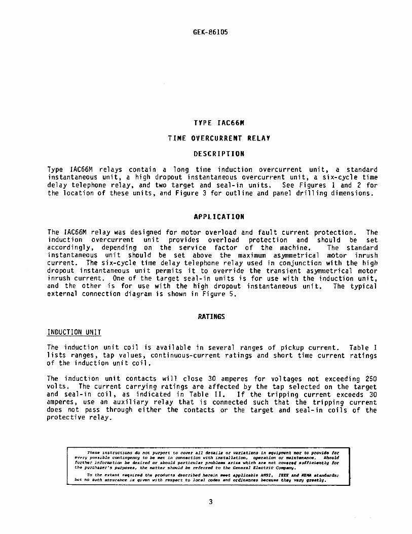
Type IAC66M relays contain a long time induction overcurrent unit, a standardinstantaneous unU, a high dropout instantaneous overcurrent unit, a six-cycle timedelay telephone relay, and two target and seal-in units. See Figures 1 and 2 forthe location of these units, and Figure 3 for outline and panel drilling dimensions.
APPLICATION
The JAC66M relay was designed for motor overload and fault current protection. Theinduction overcurrent unit provides overload protection and should be setaccordingly, depending on the service factor of the machine. The standardinstantaneous unit should be set above the maximum asymmetrical motor inrushcurrent. The six-cycle time delay telephone relay used in conjunction with the highdropout instantaneous unit permits it to override the transient asymmetrical motorinrush current. One of the target seal-in units is for use with the induction unit,and the other is for use with the high dropout instantaneous unit. The typicalexternal connection diagram is shown in Figure 5.
RATI NGS
INDUCTION UNIT
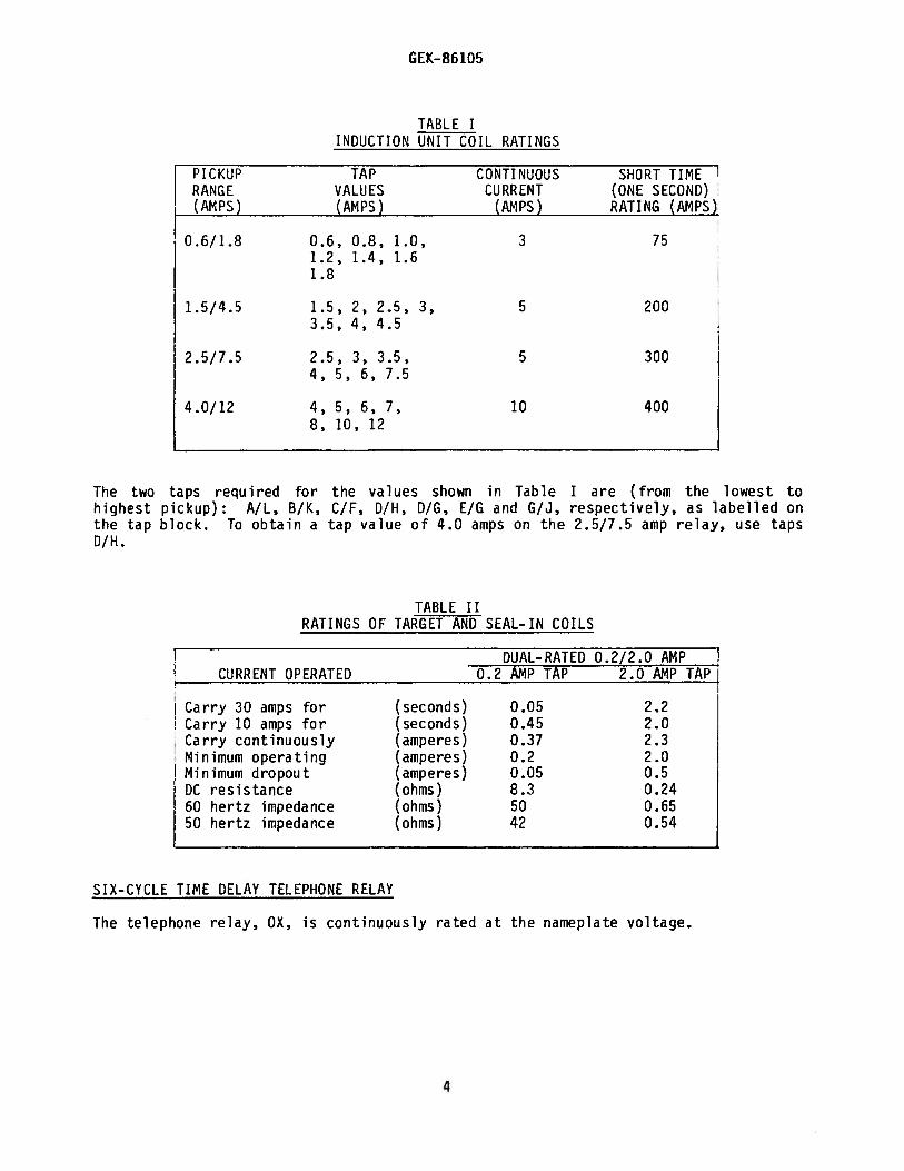
The induction unit coil is available in several ranges of pickup current. Table Ilists ranges, tap values, continuous-current ratings and short time current ratingsof the induction unit coil.
The induction unit contacts will close 30 amperes for voltages not exceeding 250volts. The current carrying ratings are affected by the tap selected on the targetand seal-in coil, as indicated in Table II. If the tripping current exceeds 30amperes, use an auxiliary relay that is connected such that the tripping currentdoes not pass through either the contacts or the target and seal—in coils of theprotective relay.
These instructions do y,o purport to cover all details or variations in equipment nor to pravide forevL’r, possible contingency to be met in connection with installation, operation or maintenance. Shouldfurther information be desired or should particular problems arise which are not covered sufficiently forthe purchaser’s purposes, the matter should be referred to the General Electric Company.
T the eetent required the products desr,-bed herein meet applicable ANSI. TESS and NEMA standards;but no such assurance Is given with respect to local codes and ordinances because they vary greatly.
3
GEK-86 105
TABLE IINDUCTION UNIT COIL RATINGS
PICKUP TAP CONTINUOUS SHORT TIMERANGE VALUES CURRENT (ONE SECOND)(AMPS) (AMPS) (AMPS) RATING (AMPS)
0.6/1.8 0.6, 0.8, 1.0, 3 751.2, 1.4, 1.61.8
1.5/4.5 1.5, 2, 2.5, 3, 5 2003.5, 4, 4.5
2.5/7.5 2.5, 3, 3.5, 5 3004, 5, 6, 7.5
4.0/12 4, 5, 6, 7, 10 4008, 10, 12
The two taps required for the values shown in Table I are (from the lowest tohighest pickup) A/L, B/K, C/F, D/[1, DIG, E/G and G/J, respectively, as labelled onthe tap block. To obtain a tap value of 4.0 amps on the 2.5/7.5 amp relay, use tapsD/H.
TABLE IIRATINGS OF TARGET AND SEAL-IN COILS
DUAL-RATED 0.2/2.0 AMPCURRENT OPERATED 0.2 AMP TAP 2.0 AMP TAP
Carry 30 amps for (seconds) 0.05 2.2Carry 10 amps for (seconds) 0.45 2.0Carry continuously (amperes) 0.37 2.3Minimum operating (amperes) 0.2 2.0Minimum dropout (amperes) 0.05 0.5DC resistance (ohms) 8.3 0.2460 hertz impedance (ohms) 50 0.6550 hertz impedance (ohms) 42 0.54
SIX-CYCLE TIME DELAY TELEPHONE RELAY
The telephone relay, OX, is continuously rated at the nameplate voltage.
4
GEK-86 105
STANDARD INSTANTANEOUS UNIT
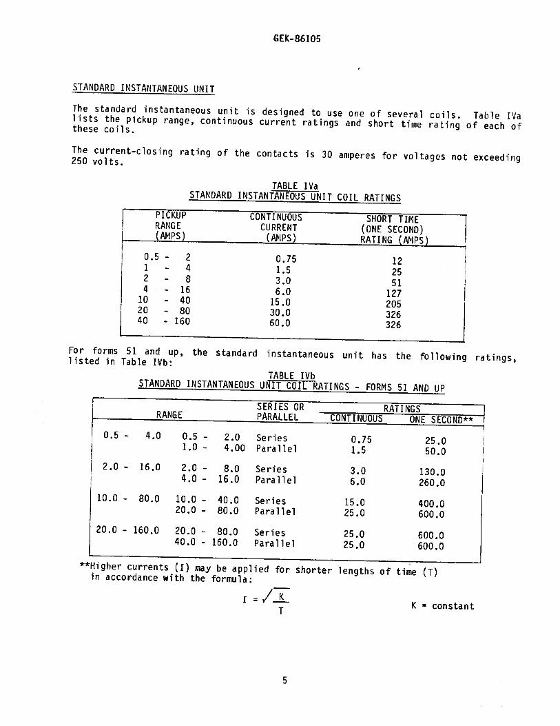
The standard instantaneous unit is designed to use one of several cofls. Tahie IValists the pickup range, continuous current ratings and short time rating of each ofthese coils.
The current-closing rating of the contacts is 30 amperes for voltages not exceeding250 volts.
TABLE IVaSTANDARD INSTANTANEOUS UNIT COIL RATINGS
PICKUP CONTINUOUS SHORT TIMERANGE CURRENT (ONE SECOND)(AMPS) (ANPS) RATING (AMPS)
0.5 - 2 0.75 121 - 4 1.5 252 - 8 3.0 514 - 16 6.0 127
10 - 40 15.0 2051 20 - 80 30.0 32640 - 160 60.0 326
For forms 51 and up, the standard instantaneous unit has the following ratings,listed in Table IVb:TABLE IVb
STANDARD INSTANTANEOUS UNIT COIL RATINGS - FORMS 51 AND UP
SERIES OR RATINGSRANGE PARALLEL CONTINUOUS ONE SECOND**
0.5 - 4.0 0.5 - 2.0 Series 0.75 25.01.0 — 4.00 Parallel 1.5 50.0
2.0 — 16.0 2.0 — 8.0 Series 3.0 130.04.0 - 16.0 Parallel 6.0 260.0
10.0 - 80.0 10.0 - 40.0 Series 15.0 400.020.0 - 80.0 Parallel 25.0 600.0
20.0 - 160.0 20.0 - SO.0 Series 25.0 600.040.0 160.0 Parallel 25.0 600.0
**Higher currents (I) may be applied for shorter lengths of time (T)in accordance with the formula:
i =K = constantT
5
GEK- 86105
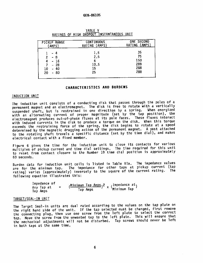
TABLE VRATINGS OF HIGH DROPOUT INSTANTANEOUS UNIT
PICKUP RANGE CONTINUOUS ONE SECOND(AMPS) RATING (AMPS) RATING (AMPS)
1 -4 1.5 35
2 —8 2.5 75
4-16 6 150
7 - 28 10.5 288
10 -40 15 288
20 -80 25 288
CHARACTERISTICS AND BURDENS
INDUCTION UNIT
The induction unit consists of a conducting disk that passes through the poles of a
permanent magnet and an electromagnet. The disk is free to rotate with a vertically
suspended shaft, but is restrained in one direction by a spring. When energized
with an alternating current of proper magnitude (set by the tap position), the
electromagnet produces out—of-phase fluxes at its pole faces. These fluxes interact
with induced currents in the disk to produce a torque on the disk. When this torque
exceeds the restraining force of the spring, the disk begins to rotate at a speed
determined by the magnetic dragging action of the permanent magnet. A post attached
to the rotating shaft travels a specific distance (set by the time dial), and makes
electrical contact with a fixed member.
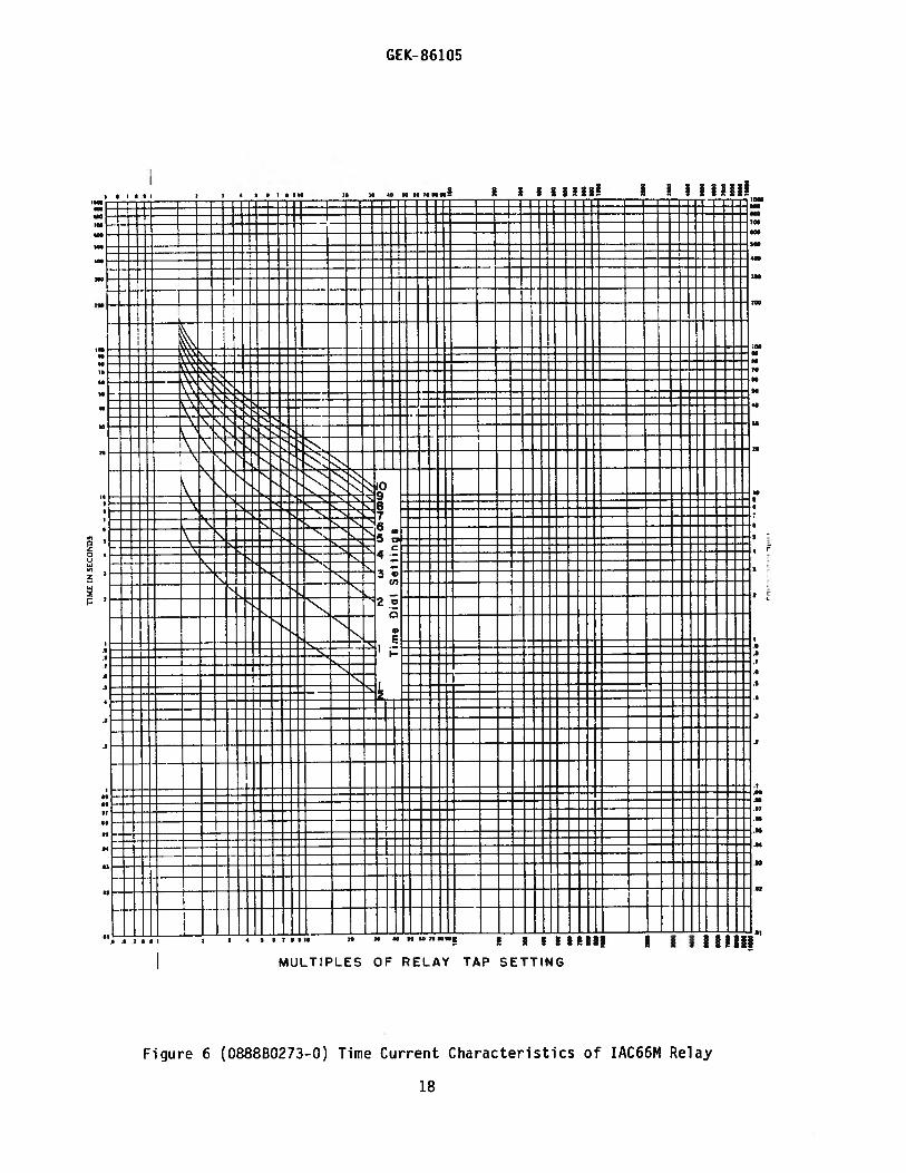
Figure 6 gives the time for the induction unit to close its contacts for various
multiples of pickup current and time dial settings. The time required for this unit
to reset from contact closure to the Number 10 time dial position is approximately
60 seconds.
Burden data for induction unit coils is listed in Table VIa. The impedance values
are for the minimum tap. The impedance for other taps at pickup current (tap
rating) varies (approximately) inversely to the square of the current rating. The
following equation illustrates this:
Impedance ofAny Tap at = (Minimum Tap AmPS)2 (ImPedance at)
Tap Amps Tap Amps Minimum Tap
TARGET/SEAL-IN UNIT
The Target Seal-in units are dual rated according to the values on the tap plate on
the right hand side of the unit. If the tap selected must be changed, first remove
the connecting plug, then use one screw from the left plate to select the correct
tap. Move the screw from the unwanted tap to the left plate. This will ensure that
the mechanical adjustments will not be disturbed. Tap screws should never be left
in both taps at the same time.
6
GEK-86 105
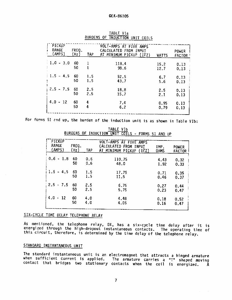
TABLE ViaBURDENS OF INDUCTION UNIT COILS
LTAAAMs
7I RANGE FREQ. CALCULATED FROM INPUT POWER(AMPs) (Hz) TAP AT MINIMUM PICKUP (12Z) WATTS FACTOR
1.0 - 3.0 60 1 118.4 15.2 0.1350 1 98.6 12.7 0.13
1.5 - 4.5 60 1.5 52.5 6.7 0.1350 1.5 43.7 5.6 0.13
2.5 - 7.5 60 2.5 18.8 2.5 0.1350 2.5 15.7 2.1 0.13
4.0 - 12 60 4 7.4 0.95 0.1350 4 6.2 0.79 0.13
For forms 51 nd up, the burden of the induction unit is as shown in Table VIb:
TABLE VIbBURDENS OF INDUCTION UNIT COILS - FORMS 51 AND UP
PICKUP- VOLT-AMPS AT FIVE AMP S
RANGE FREQ. CALCULATED FROM INPUT IMP. POL4ER(AMPS) (Hz) TAP AT MINIMUM PICKUP (12Z) OHMS FACTOR
0.6 - 1.8 60 0.6 110.75 4.43 0.3250 0.6 48.0 1.92 0.33
1.5 - 4.5 60 1.5 17.75 0.71 0.3550 1.5 11.5 0.46 0.37
2.5 - 7.5 60 2.5 6.75 0.27 0.4450 2.5 5.75 0.23 0.47
4.0 - 12 60 4.0 4.48 0.18 0.5250 4.0 4.05 0.16 0.47
SIX-CYCLE TIME DELAY TELEPHONE RELAY
As mentioned, the telephone relay, OX, has a six—cycle time delay after it isenergized through the high-dropout instantaneous contacts. The operating time ofthis circuit, therefore, is determined by the time delay of the telephone relay.
STANDARD INSTANTANEOUS UNIT
The standard instantaneous unit is an electromagnet that attracts a hinged armaturewhen sufficient current is applied. The armature carries a ‘T’ shaped movingcontact that bridges two stationary contacts when the coil is energized. A
7
GEK-86105
target is displayed when the unit operates. Pressing the button in the lower leftcorner of the relay cover resets the target.
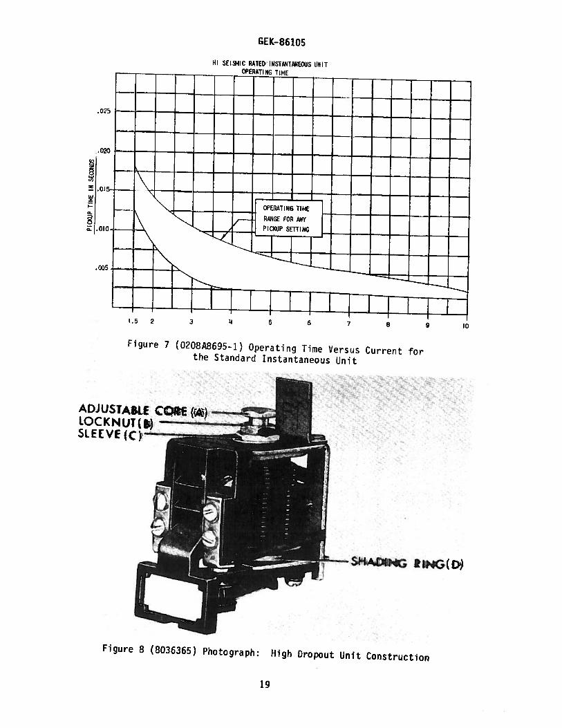
The pickup range can be adjusted continuously over a four-to-one range by using theadjustable pole piece. When the top of the core is lined up with the calibrationstampings, an approximate value of pickup can be determined. Dropout is about 40 to5O of pickup.
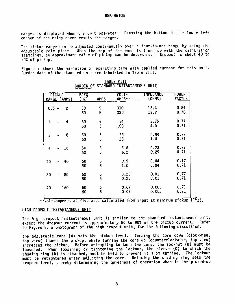
Figure 7 shows the variation of operating time with applied current for this unit.turden data of the standard unit are tabulated in Table VIII.
TABLE VIIIBURDEN OF STANDARD INSTANTANEOUS UNIT
PICKUP FREQ VOLT- IMPEDANCE POWERRANGE (AMPS) (HZ) AMPS AMPS** (OHMS) FACTOR
0.5 - 2 50 5 310 12.4 0.8460 5 330 13.2 0.78
1 — 4 50 5 94 3.75 0.7760 5 100 4.0 0.71
2 - 8 50 5 23 0.94 0.7760 5 25 1.0 0.71
4 - 16 50 5 5.8 0.23 0.7760 5 6.2 0.25 0.71
10 - 40 50 5 0.9 0.04 0.7760 5 1.0 0.04 0.71
20 - 80 50 5 0.23 0.01 0.7760 5 0.25 0.01 0.71
40 - 160 50 5 0.07 0.003 0.7160 5 0.07 0.003 0.71
**Volt..amperes at five amps calculated from input at minimum pickup (12Z).
HIGH DROPOUT INSTANTANEOUS UNIT
The high dropout instantaneous unit is similar to the standard instantaneous unit,
except the dropout current is approximately 80 to 90% of the pickup current. Refer
to Figure 8, a photograph of the high dropout unit, for the following discussion.
The adjustable core (A) sets the pickup level. Turning the core down (clockwise,
top view) lowers the pickup, while turning the core up (counterclockwise, top view)increases the pickup. Before attempting to turn the core, the locknut (B) must beloosened. When loosening or tightening the locknut, the sleeve (C) to which the
shading ring (0) is attached, must be held to prevent it from turning. The locknut
must be retightened after adjusting the core. Rotating the shading ring sets the
dropout level, thereby determining the quietness of operation when in the picked-up
8
GEK—86105
position. The core has been factory set to obtain 80% dropout at the minimum
setting, and approximately 90% dropout at the maximum setting. To change the
dropout setting, the sleeve (C) to which the shading ring (D) is attached must
always be turned in the clockwise direction (top view). This will prevent the
sleeve and shading ring assembly from being loosened. When shipped from the
factory, the whole coil is wired into the current circuit, and the lower half of the
calibration range is available. If the upper half of the calibration range is
required, the tapped section of the coil should be wired into the current circuit.
Do this by taking the black lead off stud 6 and the green lead off stud 6A. Then
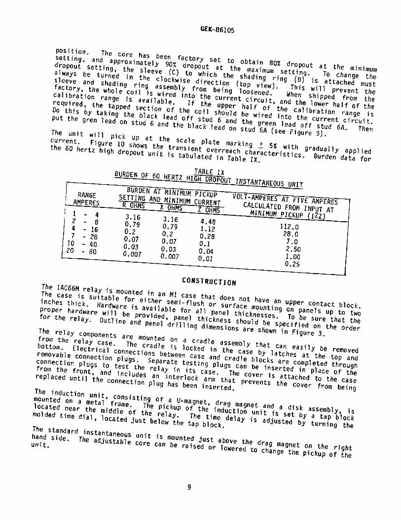
put the gren lead on stud 6 and the black lead on stud 6A (see Figure 9).The unit will pick up at the scale plate marking 5% with gradually applied
current. Figure 10 shows the transient overreach characteristics. Burden data for
the 60 hertz high dropout unit is tabulated in Table IX.
TABLE IXBURDEN OF 60 HERTZ HIGH DROPOUT INSTANTANEOUS UNITBURDEN AT MINIMUM PICKUP VOLT-AMPERES AT FIVE AMPERES
RANGE SETTING AND MINIMUM CURRENT CALCULATED FROM INPUT ATAMPERES R OHMS X OHMS Z OHMS MINIMUM PICKUP (12Z)1 - 4 3.16 3.16 4.48
112.02 - 8 0.79 0.79 1.12
28.04
- 16 0.2 0.2 0.287.0
7- 28 0.07 0.07 0.1
2.5010 - 40 0.03 0.03 0.04
1.0020 - 80 0.007 0.007 0.01
0.25
CONSTRUCTIONThe IAC66M relay is mounted in an Ml case that does not have an upper contact block.
The case is suitable for either semi-flush or surface mounting on panels up to two
inches thick. Hardware is available for all panel thicknesses. To be sure that the
proper hardware will be provided, panel thickness should be specified on the order
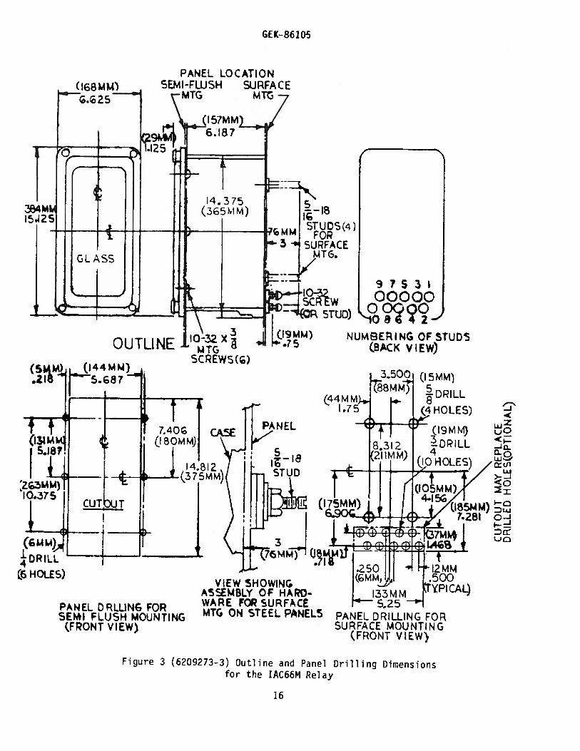
for the relay. Outline and panel drilling dimensions are shown in Figure 3.The relay components are mounted on a cradle assembly that can easily be removed
from the relay case. The cradle is locked in the case by latches at the top and
bottom. Electrical connections between case and cradle blocks are completed through
removable connection plugs. Separate testing plugs can be inserted in place of the
connectior’ plugs to test the relay in its case. The cover is attached to the case
from the front, and includes an interlock arm that prevents the cover from being
replaced until the connection plug has been inserted.The induction unit, consisting of a U-magnet, drag magnet and a disk assembly, is
mounted on a metal frame. The pickup of the induction unit is set by a tap block
located near the middle of the relay. The time delay is adjusted by turning the
molded time dial , located just below the tap block.The standard instantaneous unit is mounted just above the drag magnet on the right
hand side. The adjustable core can be raised or lowered to change the pickup of the
unit.
9

GEK—86105
The unit just above the drag magnet on the left is a target seal-in unit for theinduction unit. This seal—in unit does not have an adjustable core, but tap screwslocated on the right side of the unit can be used to change pickup.
The high dropout instantaneous unit is on the right above the standard instantaneousunit. Pickup adjustment is made with the adjustable core. There are three coilleads on units that have a four-to-one range of pickup adjustment. One of thesecoil leads is secured to an insulating bracket mounted on one of the relayterminals. By interchanging the lead on the bracket with the lead on the terminal,either the high range or the low range of the unit can be selected as required (seepage 9).
There is also a target/seal-in unit associdted with the high dropout instantaneousunit. The unit has two taps which can be selected as desired. (See page 6.)
Internal connections for the IAC66M are shown in Figure 9A. For IAC66M forms 51 andup, Figure 9B depicts the internal connections.
RECEIVING, HANDLING AND STORAGE
This relay, when not included as part of a control panel , will be shipped in acarton designed to protect it against damage. Upon receipt, immediately exam e therelay for any damage sustained in transit. If damage from rough hand ng isevident, file a damage claim at once with the transportation company, and promptlynotify the nearest General Electric Sales Office.
If the equipment is not to be installed immediately, it should be stored indoors inits original carton in a location that is dry and protected from dust, metallicchips and severe atmospheric contaminants.
ACCEPThNCE TESTS
An inspection and acceptance test should be made when the relay is received todetermine if damage has occurred in shipment, or if relay calibrations have beendisturbed.
VISUAL INSPECTION
Check the relay nameplate to see that the model number, rating and calibration range
of the relay agree with the requisition.
Remove the relay from its case and check that there are no broken or cracked moldedparts or other signs of physical damage. All screws should be tight. The drag
magnet should be securely fastened in position on its mounting shelf. No metallicparticles or any other foreign matter should be in the air gap of either the drive
magnet or the drag magnet.
Check the location of the contact brushes on the cradle and case blocks against theinternal connections diagram. The shorting bars should be in their proper locations
on the case block, and the long and short brushes on the cradle block should agreewith the internal connections diagram. Figure 4 is a sectional view of the case andcradle blocks with the connection plug in place. Note that there is an
10
GEK-86 105
auxil dry brush in each position on the case block. This brush should be formedhigh enough so tha I when the connection plug is inserted, it engages the auxi iarybrush beforn striking the main brush. An improper adjustment of the auxiliary brushcould result in a CT secondary being momentarily open-circuited in a currentcircuit.
MLCHI\NICAL INSPECT0N
The following mechanical adjustments should be checked:
Induction Unit
The moving contact should just touch the stationary contact when the time dial is atthe zero position. There should be sufficient clearance between the stationarycontact brush and its backing strip to allow for a least 1/32 inch wipe. Set thedial at the approximate setting that will be used when the relay is installed.
The disk and shaft assembly should have a vertical end play of 1/64 to 1/32 inch.The set screws for the upper pivot and lower jewel screw must be tight. The diskshould be centered (approxiiiiately) in the air gap of both the drive magnet assemblyand the drc.j magnet. The disk and shaft assembly should turn freely withoutnoticeable friction.
The stop arm assembly, located near the top of the disk shaft, should be checked forapproximately 1/64 inch deflection of the leaf spring.
[LECTRICAL TESTS
The following electrical checks should be niade upon receipt of the relay. Note thatall tests are to be made with the relay in its case and in a level position.
All alternating-current—operated devices are affected by frequency. Since non-sinusoidal waveforms can be analyzed as a fundamental frequency plus harmonics ofthe fundamental frequency, it follows that alternating—current devices (relays) willhe affected by the applied waveform.
Therefore, in order to properly test alternating-current relays a sine wave currentand/or voltage must be used. The purity of the sine wave (i.e., its freedom fromharmonics) cannot be expressed as a finite number for any particular relay; however,dfl relay using tuned circuits, RL or RC networks, or saturating electromagnets(such as time overcurrent relays), would be essentially affected by non—sinusoidalwaveforms.
Similarly, relays requiring DC control power should be tested using DC and not fullwave rectified power. Unless the rectified supply is well filtered, many relayswill not operate properly due to dips in the rectified power. Zener diodes, forexample, can turn off during dips. As a general rule, the DC source should notcontain more than 5% ripple.
Since drawout relays in service operate in their cases, they should be tested intheir cases or an equivalent steel case. This way, any magnetic effects of theenclosure will be accurately duplicated during testing. A relay may be testedwithout removing it from the panel by using a 12XLA13A test plug. This plug makesconnection only with the relay and does not disturb the shorting bars in the case.
11
GEK-86 105
The 12XLA12A test plug may also he used. Although this test plug allows greatertesting flexibility, it also requires CT shorting jumpers and greater care intesting, since connections are made to both the relay and the external circuitry.
Induction Unit
With the tap plug in the minimum position, and the time dial in the Number 1/?position, check that the current required to just close the contact is within + 5%of the minimum pickup shown on the tap block.
The operating time from the Number 5 time dial setting at five times minimum pickupsetting should be within 7% of the value shown in Figure 6.
Six-Cycle Time Delay Telephone Relay
To check the pickup voltage and time of the telephone relay, OX, use the followingprocedure.
1. Place the tap screw of the target and seal—in unit in the 0.2 amp tap.This is the upper left (front view) unit.
2. Block closed the contacts of the high-dropout instantaneous unit. This isthe upper right (front view) unit.
3. Apply DC voltage to relay terminals 9 and 10. The telephone relay shouldpick up at 80% or less of its rating.
4. Apply rated voltage to the OX unit. The contacts should close six cycles(0.1 second) after voltage is applied.
Target/Seal-in Units
There are two target/seal-in units associated with the IAC 66M(—)A relay. Thetarget/seal-in in the lower left (front view) is in the induction unit/standardinstantaneous unit circuit. The other target/seal—in is located in the upper leftof the relay (front view) and is in the high-dropout instantaneous unit/OX telephonerelay circuit.
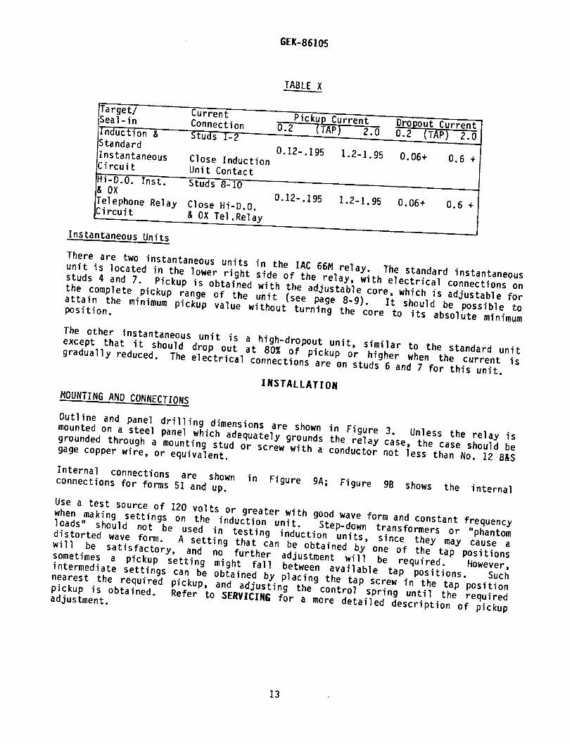
The target/seal-in units can be tested by applying DC current to the proper studsand closing the correct contact, as listed in Table X.
Reset the target/seal-in flag by pushing on the reset arm; then gradually apply theDC current until the unit picks up. It should pick up within the values in Table X.Open the appropriate contact mentioned in the table; the unit must remain sealed in.Reduce the DC current until the contacts of the target/seal—in unit open; this isthe dropout value, and should be as listed in Table X. The taps must be changed, ifdesired, according to the method given under TARGET/SEAL-IN UNIT in theCHARACTERISTICS AN!) BURDENS section.
12
GE K-86 105
TABLE X
Target/ Current Pickup Current Dropout CurrentSeal-in Connection 0.2 (TAP) 2.0 0.2 (TAP) 2.0Induction & Studs 1-2Standard
O.12-.195 1.2-1.95 0.06+ 0.6 +Instantaneous Close InductionCircuit Unit ContactHi-D.0. Inst. Studs 8-10& OX
0.12-.195 2.2-1.95 0.06+ 0.6 +Telephone Relay Close Hi-D.0.Circuit & OX Tel .Relay
Instantaneous Units
There are two instantaneous units in the JAC 66M relay. The standard instantaneousunit is located in the lower right side of the relay, with electrical connections onstuds 4 and 7. Pickup is obtained with the adjustable core, which is adjustable forthe complete pickup range of the unit (see page 8-9). It should be possible toattain the minimum pickup value without turning the core to its absolute minimum05 i t ion.
The other instantaneous unit is a high-dropout unit, similar to the standard unitexcept that it should drop out at 80% of pickup or higher when the current isgradually reduced. The electrical connections are on studs 6 and 7 for this unit.
I NSTALLAT IONMOUNTING AND CONNECTIONS
Outline and panel drilling dimensions are shown in Figure 3. Unless the relay ismounted on a steel panel which adequately grounds the relay case, the case 5hould begrounded through a mounting stud or screw with a conductor not less than No. 12 B&Sgage copper wire, or equivalent.Internal connections are shown in Figure 9A; Figure 9B shows the internalconnections for forms 51 and up.
Use a test source of 120 volts or greater with good wave form and constant frequencywhen making settings on the induction unit. Step—down transformers or “phantomloads” should not be used in testing induction units, since they may cause adistorted wave form. A setting that can be obtained by one of the tap positionswill be satisfactory, and no further adjustment will be required. however,sometimes a pickup setting might fall between available tap positions. Suchintermediate settings can be obtained by placing the tap screw in the tap positionnearest the required pickup, and adjusting the control spring until the requiredpickup is obtained. Refer to SERVICING for a more detailed description of pickupadjustment.
13
GEK-86 105
PERIODIC CHECKS AND ROUTINE MAINTENANCE
Protective relays play a vital role in the operation of a power system, and it isimportant to follow a periodic test program. The interval between periodic checkswill vary depending upon environment, type of relay and the user’s experience withperiodic testing. Until the user has accumulated enough experience to select thetest interval best suited to his individual requirements, the points listed in theACCEPTANCE TESTS section should be checked at an interval of from one to two years.
Operate the disk and shaft assembly by hand. Check that the contacts are makingwith the proper wipe. Allow the disk to reset, then check that there is no sign ofexcessive friction or a tendency to bind. Check for obstructions to disk travel.Dirt or metallic particles in the watt-metric or drag magnet gaps can interfere withthe notion of the disk.
Examine contact surfaces for tarnishing or corrosion. Fine silver contacts shouldnot be cleaned with knives, files, or abrasive paper or cloth. Knives or files mayleave scratches which increase arcing and deterioration of the contacts. Abrasivepaper or cloth may leave minute particles of insulating abrasive material in thecontacts and thus prevent closing. Use a burnishing tool specifically designed forthis purpose.
SERVICING
Induction unit pickup for any current tap is adjusted by a spring adjusting ring.If the adjustment has been disturbed, turn the ring by inserting a screw driver inthe notches around the edge; turning the ring brings the operating current of theunit into agreement with the tap setting. This adjustment also makes any settingbetween the various tap settings possible. Note, however, that if pickup is changedby turning the spring adjusting ring, then the relay will be operating at adifferent torque level, and the published time curves will not apply for thissetting.
The unit has been factory adjusted to close its contacts from any time dial positionat minimum current within 5° of the tap plug setting. If a pickup time for aparticular time dial setting and pickup multiple is outside the limits mentioned inthe acceptance tests, changing the position of the drag magnet on its supportingshelf will restore the pickup time. Moving the magnet towards the shaft decreasesthe pickup time, while moving it away from the shaft increases the pickup time. Ifthe drag magnet is moved towards the shaft, be sure that it clears the counterweighton the disk for all positions of the disk and shaft assembly in its final position.When the magnet is moved away from the shaft, its outer edge must be at least 1/8inch from the edge of the disk at the disk’s smallest radius.
Pickup and time tests should always be made with the relay in its case so that themagnetic effect of the case is the same as when the relay is in service.
RENEWAL PARTS
Sufficient quantities of renewal parts should be kept in stock for the promptreplacement of any that are worn, broken or damaged.
When ordering renewal parts, address the nearest Sales Office of the GeneralElectric Company. Specify the name of the part wanted, quantity required, andcomplete nameplate data, including the serial number, of the relay.
14

GE K- 86105
Figure 1 (8027184 - Photograph) IAC66M Relay ConstructionRelay Removed from Drawout Case (Front View)
Figure 2 (8027185 — Photograph) JAC66M Relay ConstructionRelay Removed from Drawout Case (Rear View)
ImP
15
GEK- 86105
Figure 3 (6209273—3) Outline and Panelfor the AC66M Relay
Drilling Dimensions
LLJZL)0
-1cL.a-0
>-‘:i<0
Dui0-i
DnL)Q
PANEL LOCATIONSEMI-FLUSH SURFACE
-MTG Mit7
(157MM) 76.187
)
SCWSTUD)
753’00000
00000‘—to 42—
NUMBERING OF STUDS(BAck VIEW)
EL
DRILL
4 HOLES)
(k4
DR ILL
.6HOLES)
PANEL DRLUNG FORSENI FLUSH MOUNTING
(FPONT VIEW)
VIEW SHOWINGASSEMBLY OP HAPOWARE FSURFACEMTG ON STEEL PANELS
.250(GM Mffi
33MM525 -
PANEL DRILLING FORSURFACE MOUNTING
(FRONT VIEW)
•YPI CAL)
16

GEK-86105
NOTE:AFTER ENGAGING AUXILIARY BRUSH CONNECTING PLUGTRAVELS 1/4INCH BEFORE ENGAGING THE MAIN BRUSH ONTHE TERMINAL BLOCK
Figure 4 (8025039) Photograph: Cross Section of Drawout CaseShowing Position of Auxiliary Brushes
CONNECTING PLUG MAIN BRUSH CONNECTING BLOCK
AUXILIARY BRUSH TERMINAL BLOCKSSHORTING BAR
2
S
ONE PSEO1vLY ISSHCWN
(-) DC 8US
Figure 5 (0207A7826—0) External Connections Diagram for IAC66M Relay
17
GE K- 86105
Figure 6 (088880273-0) Time Current Characteristics of IAC66M Relay
C)
MULTIPLES OF RELAY TAP SETTING
18
GE K- 86105
Ill SEIIC RATEOINSTkIIANEOUS UNITOPERATING TIME
Figure 7 (0208A8695-1) Operating Time Versus Current forthe Standard Instantaneous Unit
Figure 8 (8036365) Photograph:
I!
High Dropout Unit Construction
1.5 2 3 LI 5 6 7 8 9 10
ADJUSTABLE CORf (‘k)LOCKNUT($)SIEEVE(C)
19

1 :1/
i/I
i1
Figure 9A (0104A8596-?) Internal ConnectionsIAC66M Relay (Front View)
Diagram for the
\V [ r--fV U N( L F
NVC F Lk
N -Aht
FFNCL-fV-. Fl[N \4f f-ICK
U’ tHU ANt’ A.
HIORT F INf- H
JX H1x- 1 fLF ff-V 1..
Figure 98 (0285A8839-0) Internal Connections Diagram for theIAC66M Relay, Forms 51 and Up (Front View)
G t K- 86105
A tA. I H’I’
4
I)
20

LunSflOUR1iJP2SIJI3r1odoAQ16L)-faqJOLDPa.uaAuaLsuPA1(o-os6ws61o)a.n6
OVERREACHINP2CENT
SDI9-i]
fot[II
-—1—1-4-‘F
L4LLL_44L4_.
____
1j_L.
1lijO!
-f-H--f}Ti±r
III
M
tLt-1 -th-t-0
:E- t‘j:±:
IIIIII
—I--—l-------.
EELI--
L4:.
—,-——.———4--1—4---—+—---.-L-.-
ttL:HjzI±± LEEt 1.LL
0II“CD
-L
-4--—T--—-I
——--fF
iJ
±HII
L\_EELF
jff
LI
CDt1r- CD
t-
CDcf-
F1itIT
1FJ
tHEE
1..I
MlaID
EHII:-1
LIIJTTJt1 iir‘
F-HIII
GE K- 86105
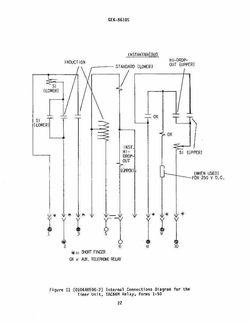
N S TAN TAN EOUS
IN DUCT ION
(WHEN USED)FOR 250 V D.C.
ZE SHCRT FU’CF
OX = AUX. TELEF+KDNE RELAY
Figure 11 (0104A8596-2) Internal Connections Diagram for theTimer Unit, IAC66M Relay, Forms 1-50
STANDARD (LOWER)
H I—DROPOUT (UPPER)
\/* \)i ‘
I 3
2 Cu d
22
GEK-861O
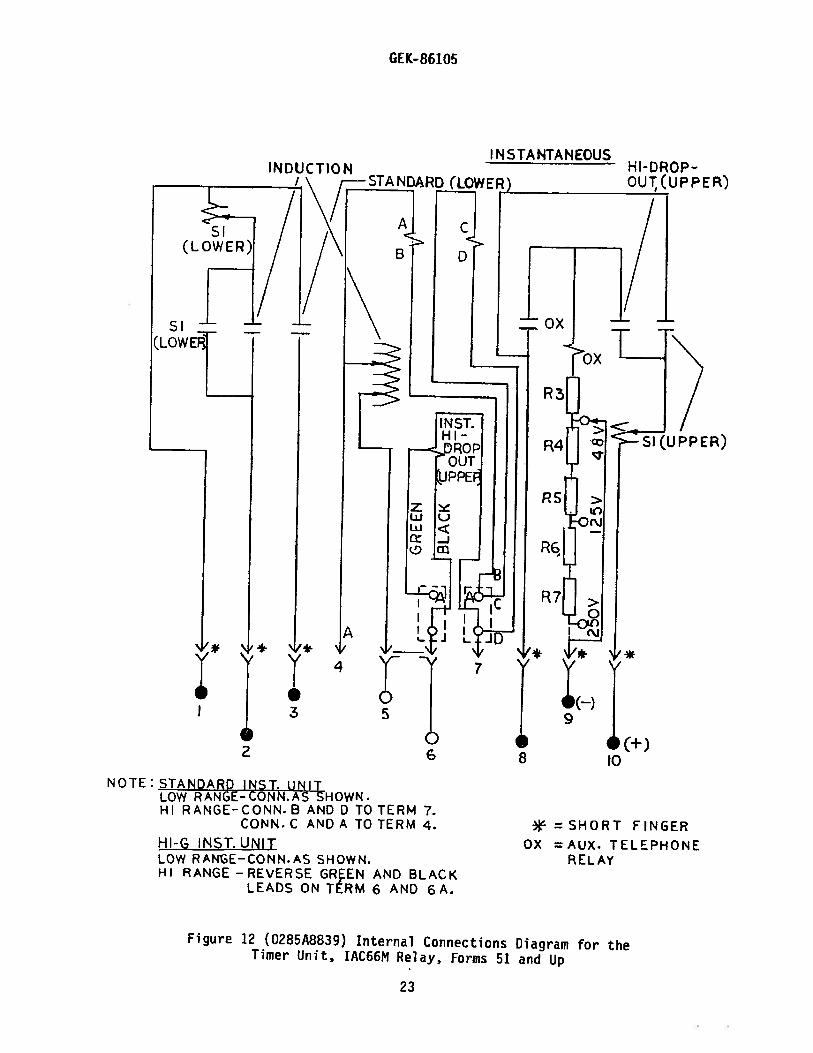
NOTE:STANDARD INST. UNITLOW RANGE- CONN AS-SHOWN.HI RANGE-C ONN.B AND D TO TERM 7.
CONN. C AND A TO TERM 4.Hi-s INSTHSL4IILOW RAN3E—CONN.AS SHOWN.HI RANGE-REVERSE GREEN AND BLACK
LEADS ON TERM 6 AND 6A.
*SHORT FINGEROX =AUX. TELEPHONE
RELAY
Figure 12 (0285A8839) Internal Connections Diagram for theTimer Unit, IAC66M Relay, Forms 51 and Up
INSTANTANEOUS
P E B’)
PER)
2 6 8 10
23

GE Power Management
215 Anderson AvenueMarkham, OntarioCanada L6E 1B3Tel: (905) 294-6222Fax: (905) 201-2098www.ge.comlindsyslpm