Embed Size (px)
Citation preview
0
Superspace Group Approach to the CrystalStructure of Thermoelectric Higher
Manganese Silicides MnSiγ
Yuzuru MiyazakiDepartment of Applied Physics, Graduate School of Engineering, Tohoku University
Japan
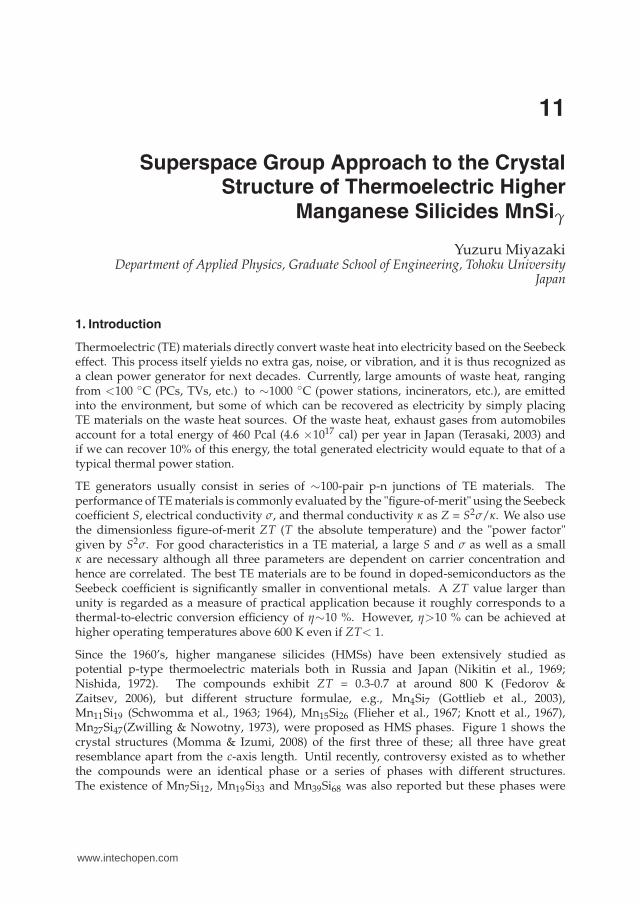
1. Introduction
Thermoelectric (TE) materials directly convert waste heat into electricity based on the Seebeckeffect. This process itself yields no extra gas, noise, or vibration, and it is thus recognized asa clean power generator for next decades. Currently, large amounts of waste heat, rangingfrom <100 ◦C (PCs, TVs, etc.) to ∼1000 ◦C (power stations, incinerators, etc.), are emittedinto the environment, but some of which can be recovered as electricity by simply placingTE materials on the waste heat sources. Of the waste heat, exhaust gases from automobilesaccount for a total energy of 460 Pcal (4.6 ×10¹⁷ cal) per year in Japan (Terasaki, 2003) andif we can recover 10% of this energy, the total generated electricity would equate to that of atypical thermal power station.
TE generators usually consist in series of ∼100-pair p-n junctions of TE materials. Theperformance of TE materials is commonly evaluated by the "figure-of-merit" using the Seebeckcoefficient S, electrical conductivity σ, and thermal conductivity κ as Z = S2σ/κ. We also usethe dimensionless figure-of-merit ZT (T the absolute temperature) and the "power factor"given by S2σ. For good characteristics in a TE material, a large S and σ as well as a smallκ are necessary although all three parameters are dependent on carrier concentration andhence are correlated. The best TE materials are to be found in doped-semiconductors as theSeebeck coefficient is significantly smaller in conventional metals. A ZT value larger thanunity is regarded as a measure of practical application because it roughly corresponds to athermal-to-electric conversion efficiency of η∼10 %. However, η>10 % can be achieved athigher operating temperatures above 600 K even if ZT< 1.
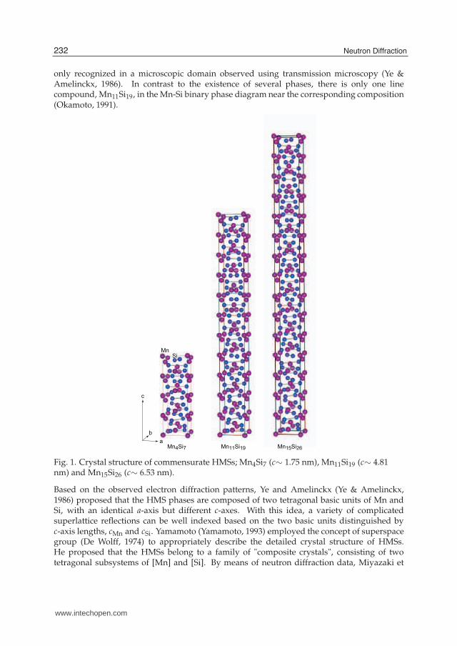
Since the 1960’s, higher manganese silicides (HMSs) have been extensively studied aspotential p-type thermoelectric materials both in Russia and Japan (Nikitin et al., 1969;Nishida, 1972). The compounds exhibit ZT = 0.3-0.7 at around 800 K (Fedorov &Zaitsev, 2006), but different structure formulae, e.g., Mn4Si7 (Gottlieb et al., 2003),Mn11Si19 (Schwomma et al., 1963; 1964), Mn15Si26 (Flieher et al., 1967; Knott et al., 1967),Mn27Si47(Zwilling & Nowotny, 1973), were proposed as HMS phases. Figure 1 shows thecrystal structures (Momma & Izumi, 2008) of the first three of these; all three have greatresemblance apart from the c-axis length. Until recently, controversy existed as to whetherthe compounds were an identical phase or a series of phases with different structures.The existence of Mn7Si12, Mn19Si33 and Mn39Si68 was also reported but these phases were
11
www.intechopen.com
2 Will-be-set-by-IN-TECH
only recognized in a microscopic domain observed using transmission microscopy (Ye &Amelinckx, 1986). In contrast to the existence of several phases, there is only one linecompound, Mn11Si19, in the Mn-Si binary phase diagram near the corresponding composition(Okamoto, 1991).
Mn11Si19 Mn15Si26Mn4Si7
MnSi
a
b
c
Fig. 1. Crystal structure of commensurate HMSs; Mn4Si7 (c∼ 1.75 nm), Mn11Si19 (c∼ 4.81nm) and Mn15Si26 (c∼ 6.53 nm).
Based on the observed electron diffraction patterns, Ye and Amelinckx (Ye & Amelinckx,1986) proposed that the HMS phases are composed of two tetragonal basic units of Mn andSi, with an identical a-axis but different c-axes. With this idea, a variety of complicatedsuperlattice reflections can be well indexed based on the two basic units distinguished byc-axis lengths, cMn and cSi. Yamamoto (Yamamoto, 1993) employed the concept of superspacegroup (De Wolff, 1974) to appropriately describe the detailed crystal structure of HMSs.He proposed that the HMSs belong to a family of "composite crystals", consisting of twotetragonal subsystems of [Mn] and [Si]. By means of neutron diffraction data, Miyazaki et
232 Neutron Diffraction
www.intechopen.com
Superspace Group Approach to the Crystal Structure of Thermoelectric Higher Manganese Silicides MnSiγ 3
al (Miyazaki, 2008) succeeded in determining the detailed modulated structure using thissuperspace group approach. In this chapter, we describe the method by which the structureof such a composite crystal is determined based on the superspace group formalism.
2. Superspace group approach
2.1 Backgrounds
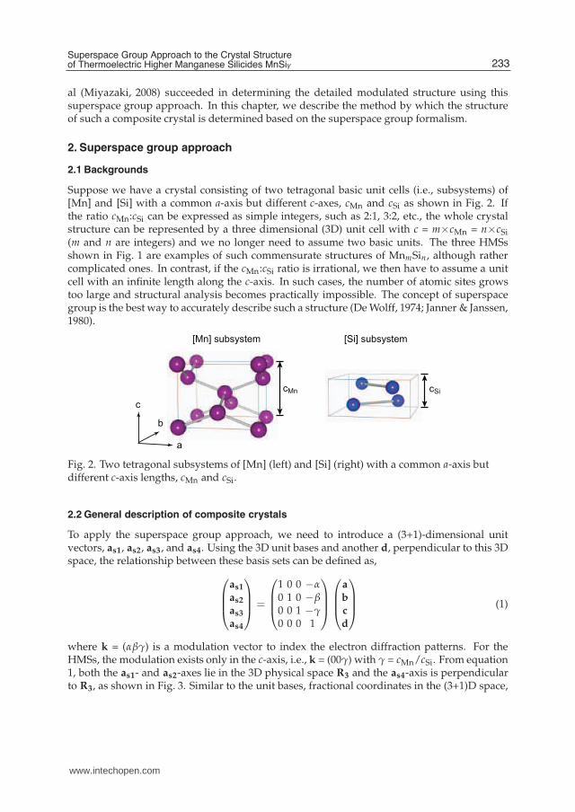
Suppose we have a crystal consisting of two tetragonal basic unit cells (i.e., subsystems) of[Mn] and [Si] with a common a-axis but different c-axes, cMn and cSi as shown in Fig. 2. Ifthe ratio cMn:cSi can be expressed as simple integers, such as 2:1, 3:2, etc., the whole crystalstructure can be represented by a three dimensional (3D) unit cell with c = m×cMn = n×cSi(m and n are integers) and we no longer need to assume two basic units. The three HMSsshown in Fig. 1 are examples of such commensurate structures of MnmSin, although rathercomplicated ones. In contrast, if the cMn:cSi ratio is irrational, we then have to assume a unitcell with an infinite length along the c-axis. In such cases, the number of atomic sites growstoo large and structural analysis becomes practically impossible. The concept of superspacegroup is the best way to accurately describe such a structure (De Wolff, 1974; Janner & Janssen,1980).
a
b
c
cMn cSi
[Mn] subsystem [Si] subsystem
Fig. 2. Two tetragonal subsystems of [Mn] (left) and [Si] (right) with a common a-axis butdifferent c-axis lengths, cMn and cSi.
2.2 General description of composite crystals
To apply the superspace group approach, we need to introduce a (3+1)-dimensional unitvectors, as1, as2, as3, and as4. Using the 3D unit bases and another d, perpendicular to this 3Dspace, the relationship between these basis sets can be defined as,
as1
as2
as3
as4
=
1 0 0 −α0 1 0 −β0 0 1 −γ0 0 0 1
a
b
c
d
(1)
where k = (αβγ) is a modulation vector to index the electron diffraction patterns. For theHMSs, the modulation exists only in the c-axis, i.e., k = (00γ) with γ = cMn/cSi. From equation1, both the as1- and as2-axes lie in the 3D physical space R3 and the as4-axis is perpendicularto R3, as shown in Fig. 3. Similar to the unit bases, fractional coordinates in the (3+1)D space,
233Superspace Group Approach to the Crystal Structureof Thermoelectric Higher Manganese Silicides MnSiγ
www.intechopen.com
4 Will-be-set-by-IN-TECH
xs1, xs2, xs3 and xs4 can be defined as,
xS1xS2xS3xS4
=
1 0 0 00 1 0 00 0 1 0α β γ 1
xyzt
(2)
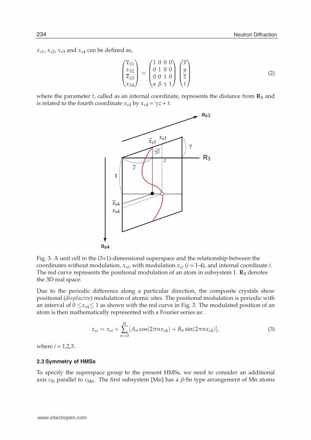
where the parameter t, called as an internal coordinate, represents the distance from R3 andis related to the fourth coordinate xs4 by xs4 = γz + t.
t
γ
R3
as4
as3
xs4
xs4
xs3xs3
γz
z
z
Fig. 3. A unit cell in the (3+1)-dimensional superspace and the relationship between thecoordinates without modulation, xsi, with modulation xsi (i = 1-4), and internal coordinate t.The red curve represents the positional modulation of an atom in subsystem 1. R3 denotesthe 3D real space.
Due to the periodic difference along a particular direction, the composite crystals showpositional (displacive) modulation of atomic sites. The positional modulation is periodic withan interval of 0 ≤xs4≤ 1 as shown with the red curve in Fig. 3. The modulated position of anatom is then mathematically represented with a Fourier series as:
xsi = xsi +m
∑n=0
[An cos(2πnxs4) + Bn sin(2πnxs4)], (3)
where i = 1,2,3.
2.3 Symmetry of HMSs
To specify the superspace group to the present HMSs, we need to consider an additionalaxis cSi parallel to cMn. The first subsystem [Mn] has a β-Sn type arrangement of Mn atoms
234 Neutron Diffraction
www.intechopen.com
Superspace Group Approach to the Crystal Structure of Thermoelectric Higher Manganese Silicides MnSiγ 5
classified under the 3D space group of I41/amd. For the second subsystem [Si], originallyhaving dimensions of a/
√2 × a/
√2 × cSi, the a-axis length is adjusted to that of [Mn]. The
Si atoms are at the origin and the equivalent positions generated by the P4/nnc space group.According to Yamamoto (Yamamoto, 1993), the most appropriate (3+1)D superspace group isdesignated as P : I41/amd : 11ss (Mn) W : P4/nnc : q1q1 (Si), or based on the modulationvector k = (00γ) more conveniently as I41/amd(00γ)00ss.
Based on the adopted superspace group, the translation parts for the [Mn] subsystem areexpressed as:+(0, 0, 0, 0); +(1/2, 1/2, 1/2, 0),with symmetry operations represented as:(i) x, y, z, t;(ii) -y, x+1/2, z+1/4, t;(iii) -x, y, z, t+1/2;(iv) -x, -y, z, t;(v) -y, -x+1/2, z+1/4, t+1/2;(vi) y, -x+1/2, z+1/4, t;(vii) x, -y, z, t+1/2;(viii) y, x+1/2, z+1/4, t+1/2;(ix) -x, -y+1/2, -z+1/4, -t;(x) y, -x, -z, -t;(xi) x, -y+1/2, -z+1/4, -t+1/2;(xii) x, y+1/2, -z+1/4, -t;(xiii) y, x, -z, -t+1/2;(xiv) -y, x, -z, -t;(xv) -x, y+1/2, -z+1/4, -t+1/2;(xvi) -y, -x, -z, -t+1/2.
The translation parts and the symmetry operation for the [Si] subsystem can be obtained bysimply interchanging the third and the fourth components.
2.4 Structural modulation
Polycrystalline samples were prepared in a tetra-arc-type furnace under an Ar atmosphereusing tungsten electrodes and a water-cooled copper hearth. Appropriate amounts of Mn(99.9%) and Si (99.99%) powders were mixed in an alumina mortar and pressed into pellets.The pellets were melted four times, and turned over each time to obtain full homogeneity. Asthe satellite reflections were observed up to eighth order in the electron diffraction patterns,positional modulation of the atomic sites was introduced taken to the eighth order of cosineand sine components of the Fourier terms, An and Bn (n= 0-8), of equation 3.
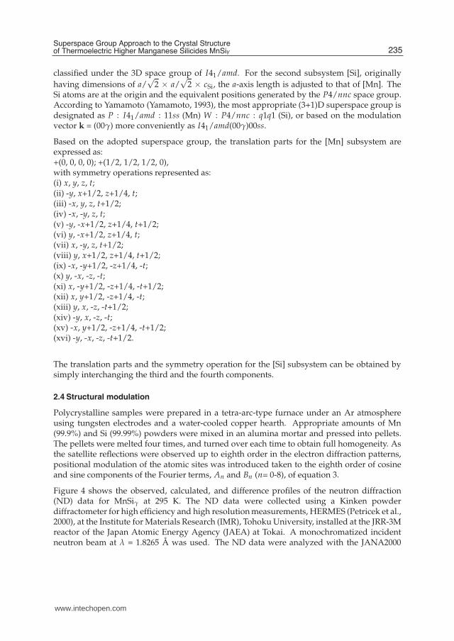
Figure 4 shows the observed, calculated, and difference profiles of the neutron diffraction(ND) data for MnSiγ at 295 K. The ND data were collected using a Kinken powderdiffractometer for high efficiency and high resolution measurements, HERMES (Petricek et al.,2000), at the Institute for Materials Research (IMR), Tohoku University, installed at the JRR-3Mreactor of the Japan Atomic Energy Agency (JAEA) at Tokai. A monochromatized incidentneutron beam at λ = 1.8265 Å was used. The ND data were analyzed with the JANA2000
235Superspace Group Approach to the Crystal Structureof Thermoelectric Higher Manganese Silicides MnSiγ
www.intechopen.com
6 Will-be-set-by-IN-TECH
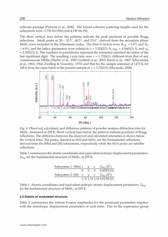
software package (Petricek et al., 2000). The bound coherent scattering lengths used for therefinement were -3.730 fm (Mn) and 4.149 fm (Si).
The short vertical lines below the patterns indicate the peak positions of possible Braggreflections. Small peaks at 2θ∼ 32.5◦ , 40.5◦ , and 53.0◦ , derived from the secondary phaseMnSi, were excluded in the refinement cycles. The final R factors were Rwp = 9.8% and Rp
= 6.9%, and the lattice parameters were refined to a = 5.5242(3) Å, cMn = 4.3665(3) Å, and cSi= 2.5202(3) Å. The numbers in parentheses represent the estimated standard deviation of thelast significant digit. The resulting c-axis ratio was γ = 1.7326(1), different from that of anycommensurate HMSs (Flieher et al., 1967; Gottlieb et al., 2003; Knott et al., 1967; Schwommaet al., 1963; 1964; Zwilling & Nowotny, 1973) and that for the sample annealed at 1273 K for168 h from the same batch of the present sample of γ = 1.7361(1) (Miyazaki, 2008).
14012010080604020
2θ (deg.)
Inte
nsi
ty (
a.u
.)
1010
2000
2111
1101
5010,
4310
3120
3210
2221
1120
4000
2111
Fig. 4. Observed, calculated, and difference patterns of powder neutron diffraction data forMnSiγ measured at 295 K. Short vertical lines below the patterns indicate positions of Braggreflections. The difference between the observed and calculated intensities is shown belowthe vertical lines. The peaks, denoted as hkl0 and hk0m, are the fundamental reflectionsderived from the [Mn] and [Si] subsystems, respectively, while the hklm peaks are satellitereflections.
Table 1 summarizes the atomic coordinates and equivalent isotropic displacement parameters,Ueq, for the fundamental structure of MnSiγ at 295 K.
Subsystem 1: [Mn] x y z Ueq (Å2)0 0 0 0.0057(12)
Subsystem 2: [Si] x y z Ueq (Å2)1/4 1/4 1/4 0.0139(12)
Table 1. Atomic coordinates and equivalent isotropic atomic displacement parameters, Ueq,for the fundamental structure of MnSiγ at 295 K.
2.5 Details of modulated structure
Table 2 summarizes the refined Fourier amplitudes for the positional parameters togetherwith the anisotropic displacement parameters of each atom. Due to the superspace group
236 Neutron Diffraction
www.intechopen.com
Superspace Group Approach to the Crystal Structure of Thermoelectric Higher Manganese Silicides MnSiγ 7
symmetry, the number of refinable parameters of the Fourier terms is limited. Only eventerms of the sine wave along the z-direction, i.e., B2z, B4z, B6z, and B8z, are allowed for the Mnatoms. In contrast, odd terms of the sine and cosine waves are allowed for both the x and ycomponents for the Si atoms, along with B4z and B8z terms. The amplitudes of each cosinewave component in the x-y plane, such as A1x and A1y, are equal, whereas those of each sinewave are equal but their signs are opposite.
Subsystem 1: [Mn] x y zB2 0 0 -0.0142(12)B4 0 0 0.017(2)B6 0 0 0B8 0 0 0U11 = U22 = 0.002(2) (Å2)U33 = 0.013(2) (Å2)
Subsystem 2: [Si] x y zA1 0.0772(3) = A1x 0B1 = A1x = -A1x 0A3 0.0103(3) = A3x 0B3 = -A3x = A3x 0B4 0 0 -0.0441(19)A5 -0.0040(5) = A5x 0B5 = A5x = -A5x 0A7 -0.0034(7) = A7x 0B7 = -A7x = A7x 0B8 0 0 0.017(4)U11 = U22 = 0.009(2) (Å2)U33 = 0.023(2) (Å2)
Table 2. Refined positional modulation wave components and anisotropic displacementparameters, Uij, for MnSiγ.
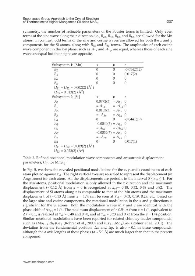
In Fig. 5, we show the revealed positional modulations for the x, y, and z coordinates of eachatom plotted against xs4. The right vertical axes are re-scaled to represent the displacement (inAngstroms) for each atom. All the displacements are periodic in the interval 0 ≤xs4≤ 1. Forthe Mn atoms, positional modulation is only allowed in the z direction and the maximumdisplacement (∼0.12 Å) from z = 0 is recognized at xs4∼ 0.18, 0.32, 0.68 and 0.82. Thedisplacement of Si atoms along z is comparable to that of the Mn atoms and the maximumdisplacement of (∼0.13 Å) from z = 1/4 can be seen at xs4∼ 0.03, 0.19, 0.28, etc. Based onthe large sine and cosine components, the rotational modulation in the x and y directions issignificant for the Si atoms. Both the modulation waves in x and y are identical with thephase-shift of ∆xs4 = 1/4. The maximum displacement of ∼0.54 Å from x = 1/4, equivalent to∆x∼ 0.1, is realized at xs4∼ 0.48 and 0.98, and at xs4∼ 0.23 and 0.73 from the y = 1/4 position.Similar rotational modulations have been reported for related chimney-ladder compounds,such as (Mo1−xRhx)Geγ (Rohrer et al., 2000) and (Cr1−xMox)Geγ (Rohrer et al., 2001). Thedeviation from the fundamental position, ∆x and ∆y, is also ∼0.1 in these compounds,although the a-axis lengths of these phases (a∼ 5.9 Å) are much larger than that in the presentcompound.
237Superspace Group Approach to the Crystal Structureof Thermoelectric Higher Manganese Silicides MnSiγ
www.intechopen.com
8 Will-be-set-by-IN-TECH
1.00.80.60.40.20
-0.2
0
0.2
dis
pla
cem
en
t (Å
)
0.35
0.25
0.15
-0.05
0
0.05 Mn x,yz
0.30
0.25
0.20
0.6
0.3
0
-0.6
-0.3
Si
x y
po
sitio
n z
Si
-0.1
0
0.1
-0.2
0.2
xs4
Fig. 5. Revealed positional modulations of the Mn and Si atoms plotted as a function of thefourth superspace coordinate, xs4. The right vertical axes are re-scaled to represent thedisplacement for each atom.
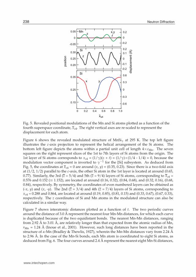
Figure 6 shows the revealed modulated structure of MnSiγ at 295 K. The top left figureillustrates the c-axis projection to represent the helical arrangement of the Si atoms. Thebottom left figure depicts the atoms within a partial unit cell of length 4×cMn. The sevensquares on the right represent slices of the 1st to 7th layers of Si atoms from the origin. The1st layer of Si atoms corresponds to xs4 = (1/γ)(z + t) = (1/γ)×(1/4 - 1/4) = 0, because themodulation vector component is inverted to γ−1 for the [Si] subsystem. As deduced fromFig. 5, the coordinates at xs4 = 0 are around (x, y) = (0.35, 0.23). Since there is a two-fold axisat (1/2, 1/2) parallel to the c-axis, the other Si atom in the 1st layer is located at around (0.65,0.77). Similarly, the 3rd (z = 5/4) and 5th (z = 9/4) layers of Si atoms, corresponding to xs4 =0.576 and 0.152 (≡ 1.152), are located at around (0.16, 0.32), (0.84, 0.68), and (0.32, 0.16), (0.68,0.84), respectively. By symmetry, the coordinates of even numbered layers can be obtained as(-x, y) and (x, -y). The 2nd (z = 3/4) and 4th (z = 7/4) layers of Si atoms, corresponding toxs4 = 0.288 and 0.864, are located at around (0.19, 0.85), (0.81, 0.15) and (0.33, 0.67), (0.67, 0.33),respectively. The z coordinates of Si and Mn atoms in the modulated structure can also becalculated in a similar way.
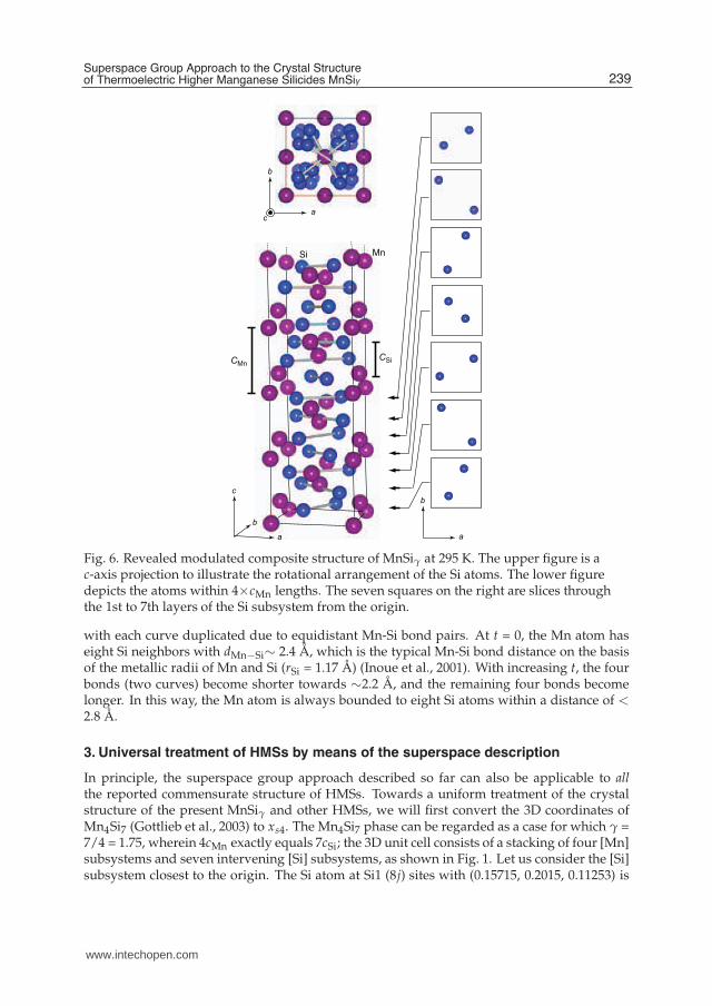
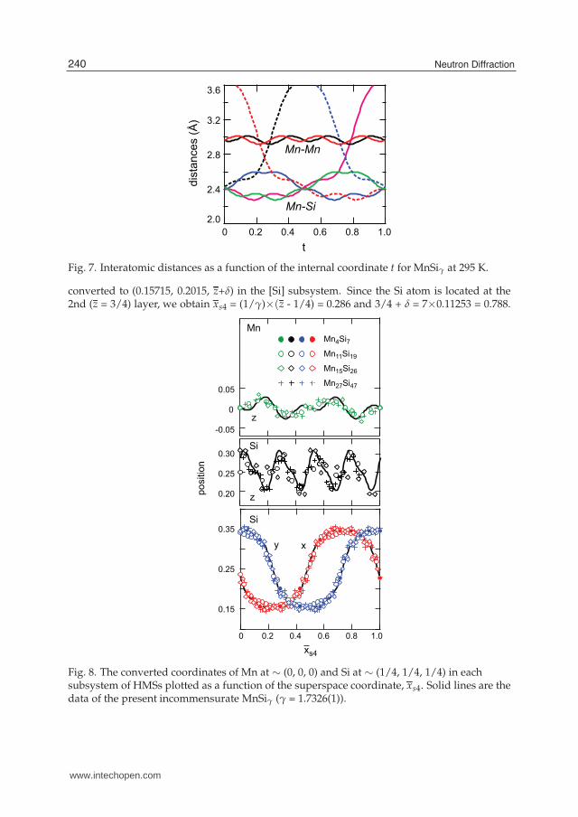
Figure 7 shows interatomic distances plotted as a function of t. The two periodic curvesaround the distance of 3.0 Å represent the nearest four Mn-Mn distances, for which each curveis duplicated because of the two equidistant bonds. The nearest Mn-Mn distances, rangingfrom 2.92 Å to 3.01 Å, are relatively longer than that expected from the atomic radius of Mn,rMn = 1.24 Å (Inoue et al., 2001). However, such long distances have been reported in thestructure of α-Mn (Bradley & Thewlis, 1927), wherein the Mn-Mn distances vary from 2.24 Åto 2.96 Å. In the case of the Mn-Si bonds, each Mn atom is coordinated to eight Si atoms, asdeduced from Fig. 6. The four curves around 2.4 Å represent the nearest eight Mn-Si distances,
238 Neutron Diffraction
www.intechopen.com
Superspace Group Approach to the Crystal Structure of Thermoelectric Higher Manganese Silicides MnSiγ 9
MnSi
CMnCSi
a
c
b
a
b
a
b
c
Fig. 6. Revealed modulated composite structure of MnSiγ at 295 K. The upper figure is ac-axis projection to illustrate the rotational arrangement of the Si atoms. The lower figuredepicts the atoms within 4×cMn lengths. The seven squares on the right are slices throughthe 1st to 7th layers of the Si subsystem from the origin.
with each curve duplicated due to equidistant Mn-Si bond pairs. At t = 0, the Mn atom haseight Si neighbors with dMn−Si∼ 2.4 Å, which is the typical Mn-Si bond distance on the basisof the metallic radii of Mn and Si (rSi = 1.17 Å) (Inoue et al., 2001). With increasing t, the fourbonds (two curves) become shorter towards ∼2.2 Å, and the remaining four bonds becomelonger. In this way, the Mn atom is always bounded to eight Si atoms within a distance of <2.8 Å.
3. Universal treatment of HMSs by means of the superspace description
In principle, the superspace group approach described so far can also be applicable to allthe reported commensurate structure of HMSs. Towards a uniform treatment of the crystalstructure of the present MnSiγ and other HMSs, we will first convert the 3D coordinates ofMn4Si7 (Gottlieb et al., 2003) to xs4. The Mn4Si7 phase can be regarded as a case for which γ =7/4 = 1.75, wherein 4cMn exactly equals 7cSi; the 3D unit cell consists of a stacking of four [Mn]subsystems and seven intervening [Si] subsystems, as shown in Fig. 1. Let us consider the [Si]subsystem closest to the origin. The Si atom at Si1 (8j) sites with (0.15715, 0.2015, 0.11253) is
239Superspace Group Approach to the Crystal Structureof Thermoelectric Higher Manganese Silicides MnSiγ
www.intechopen.com
10 Will-be-set-by-IN-TECH
3.6
3.2
2.8
2.4
2.01.00.80.60.40.20
dis
tan
ces
(Å)
t
Mn-Mn
Mn-Si
Fig. 7. Interatomic distances as a function of the internal coordinate t for MnSiγ at 295 K.
converted to (0.15715, 0.2015, z+δ) in the [Si] subsystem. Since the Si atom is located at the2nd (z = 3/4) layer, we obtain xs4 = (1/γ)×(z - 1/4) = 0.286 and 3/4 + δ = 7×0.11253 = 0.788.
-0.05
0
0.05
0.30
0.25
0.20po
sitio
n
z
Si
1.00.80.60.40.20
0.35
0.25
0.15
Mn11Si19
Mn15Si26
Mn27Si47
Mn4Si7
Si
xy
Mn
z
xs4
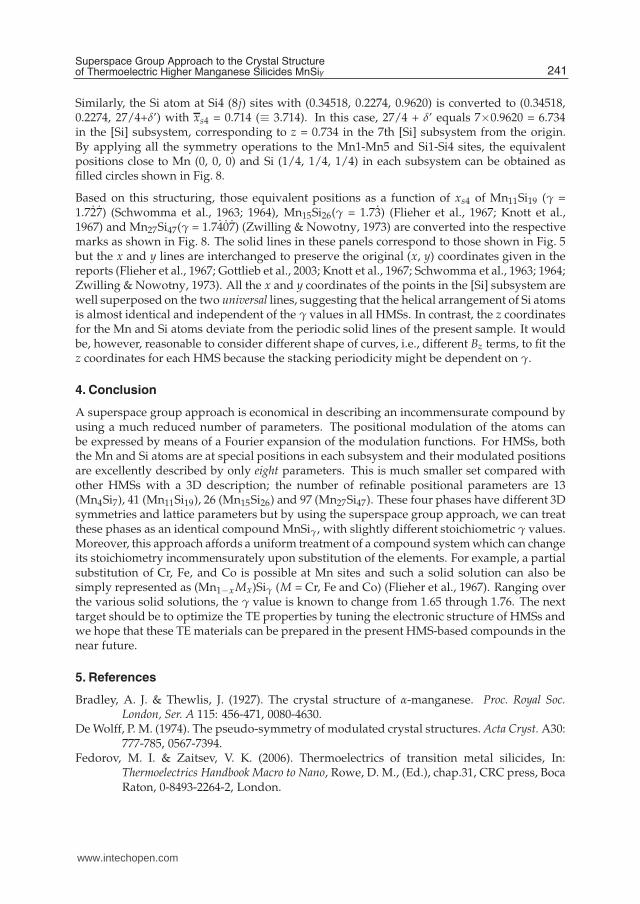
Fig. 8. The converted coordinates of Mn at ∼ (0, 0, 0) and Si at ∼ (1/4, 1/4, 1/4) in eachsubsystem of HMSs plotted as a function of the superspace coordinate, xs4. Solid lines are thedata of the present incommensurate MnSiγ (γ = 1.7326(1)).
240 Neutron Diffraction
www.intechopen.com
Superspace Group Approach to the Crystal Structure of Thermoelectric Higher Manganese Silicides MnSiγ 11
Similarly, the Si atom at Si4 (8j) sites with (0.34518, 0.2274, 0.9620) is converted to (0.34518,0.2274, 27/4+δ’) with xs4 = 0.714 (≡ 3.714). In this case, 27/4 + δ’ equals 7×0.9620 = 6.734in the [Si] subsystem, corresponding to z = 0.734 in the 7th [Si] subsystem from the origin.By applying all the symmetry operations to the Mn1-Mn5 and Si1-Si4 sites, the equivalentpositions close to Mn (0, 0, 0) and Si (1/4, 1/4, 1/4) in each subsystem can be obtained asfilled circles shown in Fig. 8.
Based on this structuring, those equivalent positions as a function of xs4 of Mn11Si19 (γ =1.72̇7̇) (Schwomma et al., 1963; 1964), Mn15Si26(γ = 1.73̇) (Flieher et al., 1967; Knott et al.,1967) and Mn27Si47(γ = 1.74̇0̇7̇) (Zwilling & Nowotny, 1973) are converted into the respectivemarks as shown in Fig. 8. The solid lines in these panels correspond to those shown in Fig. 5but the x and y lines are interchanged to preserve the original (x, y) coordinates given in thereports (Flieher et al., 1967; Gottlieb et al., 2003; Knott et al., 1967; Schwomma et al., 1963; 1964;Zwilling & Nowotny, 1973). All the x and y coordinates of the points in the [Si] subsystem arewell superposed on the two universal lines, suggesting that the helical arrangement of Si atomsis almost identical and independent of the γ values in all HMSs. In contrast, the z coordinatesfor the Mn and Si atoms deviate from the periodic solid lines of the present sample. It wouldbe, however, reasonable to consider different shape of curves, i.e., different Bz terms, to fit thez coordinates for each HMS because the stacking periodicity might be dependent on γ.
4. Conclusion
A superspace group approach is economical in describing an incommensurate compound byusing a much reduced number of parameters. The positional modulation of the atoms canbe expressed by means of a Fourier expansion of the modulation functions. For HMSs, boththe Mn and Si atoms are at special positions in each subsystem and their modulated positionsare excellently described by only eight parameters. This is much smaller set compared withother HMSs with a 3D description; the number of refinable positional parameters are 13(Mn4Si7), 41 (Mn11Si19), 26 (Mn15Si26) and 97 (Mn27Si47). These four phases have different 3Dsymmetries and lattice parameters but by using the superspace group approach, we can treatthese phases as an identical compound MnSiγ, with slightly different stoichiometric γ values.Moreover, this approach affords a uniform treatment of a compound system which can changeits stoichiometry incommensurately upon substitution of the elements. For example, a partialsubstitution of Cr, Fe, and Co is possible at Mn sites and such a solid solution can also besimply represented as (Mn1−x Mx)Siγ (M = Cr, Fe and Co) (Flieher et al., 1967). Ranging overthe various solid solutions, the γ value is known to change from 1.65 through 1.76. The nexttarget should be to optimize the TE properties by tuning the electronic structure of HMSs andwe hope that these TE materials can be prepared in the present HMS-based compounds in thenear future.
5. References
Bradley, A. J. & Thewlis, J. (1927). The crystal structure of α-manganese. Proc. Royal Soc.London, Ser. A 115: 456-471, 0080-4630.
De Wolff, P. M. (1974). The pseudo-symmetry of modulated crystal structures. Acta Cryst. A30:777-785, 0567-7394.
Fedorov, M. I. & Zaitsev, V. K. (2006). Thermoelectrics of transition metal silicides, In:Thermoelectrics Handbook Macro to Nano, Rowe, D. M., (Ed.), chap.31, CRC press, BocaRaton, 0-8493-2264-2, London.
241Superspace Group Approach to the Crystal Structureof Thermoelectric Higher Manganese Silicides MnSiγ
www.intechopen.com
12 Will-be-set-by-IN-TECH
Flieher, G.; Vollenkle, H.; Nowotny, H. (1967). Die Kristallstruktur von Mn15Si26, Monatsh.Chem. 98: 2173-2179, 0026-9247.
Gottlieb, U.; Sulpice, A.; Lambert-Andron, B.; Laborde, O. (2003). Magnetic Properties ofSingle Crystalline Mn4Si7, J. Alloys Compd. 361: 13-18, 0925-8388.
Inoue, T.; Chikazumi, S.; Nagasaki, S; Tanuma, S. (2001). Agne Periodic Table, AGNETechnology Center, 978-4-901496-37-7,Tokyo.
Janner, A. & Janssen, T. (1980). Symmetry of incommensurate crystal phases. II.Incommensurate basic structure, Acta Cryst. A36: 408-415, 0567-7394.
Knott, H. W.; Mueller, M. H.; Heaton, L. (1967). The Crystal Structure of Mn15Si26, Acta Cryst.23: 549-555, 0365-110X.
Miyazaki, Y.; Igarashi, D.; Hayashi, K.; Kajitani, T.; Yubuta, K. (20080. Modulated CrystalStructure of Chimney-Ladder Higher Manganese Silicides MnSiγ (γ∼ 1.74), Phys.Rev. B 78, 214104 (8 pages), 1098-0121.
Momma, K. & Izumi, F. (2008). VESTA: a three-dimensional visualization system for electronicand structural analysis. J. Appl. Cryst. 41: 653-658, 0021-8898.
Nikitin, E. N.; Tarasov, V. I.; Tamarin, P. V. (1969). Thermal and electrical properties of thehigher manganese silicide from 4.2 to 1300 K and its structure, Sov. Phys. Solid State11: 187-189, 0038-5654.
Nishida, I. (1973). Semiconducting properties of nonstoichiometric manganese silicides. J.Mater. Sci. 7: 435-440, 0022-2461.
Ohoyama, K.; Kanouchi, T.; Nemoto, K.; Ohashi, M.; Kajitani, T.; Yamaguchi, Y. (1998). Thenew neutron powder diffractometer with a multi-detector system for high-efficiencyand high-resolution measurements, Jpn. J. Appl. Phys. 37: 3319-3326, 0021-4922.
Okamoto, H. (1991). Mn-Si (Manganese-Silicon), J. Phase Equilibria 12: 505-507, 1054-9714.Petricek, V.; Dusek, M.; Palatinus, L. (2000). JANA2000 The crystallographic computing system.
Institute of Physics, Praha, Czech Republic.Rohrer, F. E.; Lind, H.; Eriksson, L.; Larsson, A. K.; Lidin, S. (2000). One the question of
commensurability - The Nowotny chimney-ladder structures revisited. Z. Kristallogr.215: 650-660, 1433-7266.
Rohrer, F. E.; Lind, H.; Eriksson, L.; Larsson, A. K.; Lidin, S. (2001). Incommensuratelymodulated Nowotny Chimney-ladder phases: Cr1−xMoxGe∼1.75 with x = 0.65 and0.84. Z. Kristallogr. 216: 190-198, 1433-7266.
Schwomma, O.; Nowotny, H.; Wittmann, A. (1963). Die Kristallarten RuSi1.5, RuGe1.5 undMnSi∼1.7, Monatsh. Chem. 94: 681-685, 0026-9247.
Schwomma, O.; Preisinger, A.; Nowotny, H.; Wittmann, A. (1964) Die Kristallstrukturvon Mn11Si19 und deren Zusammenhang mit Disilicid-Typen, Monatsh. Chem. 95:1527-1537, 0026-9247.
Terasaki, I. (2003). Thermoelectric cobalt oxides. Parity 64-67 (in Japanese).Yamamoto, A. (1993). Determination of Composite Crystal Structures and Superspace Groups,
Acta Cryst. A 49: 831-846, 0567-7394.Ye, H. Q. & Amelinckx, S. (1986). High-Resolution Electron Microscopic Study of Manganese
Silicides MnSi2−x, J. Solid State Chem. 61: 8-39, 0022-4596.Zwilling, G. & Nowotny, H. (1973). Zur Struktur der Defekt-Mangansilicide, Monatsh. Chem.
104: 668-675, 0026-9247.
242 Neutron Diffraction
www.intechopen.com
Neutron DiffractionEdited by Prof. Irisali Khidirov
ISBN 978-953-51-0307-3Hard cover, 286 pagesPublisher InTechPublished online 14, March, 2012Published in print edition March, 2012
InTech EuropeUniversity Campus STeP Ri Slavka Krautzeka 83/A 51000 Rijeka, Croatia Phone: +385 (51) 770 447 Fax: +385 (51) 686 166www.intechopen.com
InTech ChinaUnit 405, Office Block, Hotel Equatorial Shanghai No.65, Yan An Road (West), Shanghai, 200040, China
Phone: +86-21-62489820 Fax: +86-21-62489821
Now neutron diffraction is widely applied for the research of crystal, magnetic structure and internal stress ofcrystalline materials of various classes, including nanocrystalls. In the present book, we make practically shortexcursion to modern state of neutron diffraction researches of crystal materials of various classes. The bookcontains a helpful information on a modern state of neutron diffraction researches of crystals for the broadspecialists interested in studying crystals and purposeful regulation of their service characteristics, since thecrystal structure, basically, defines their physical and mechanical properties. Some chapters of the book havemethodical character that can be useful to scientists, interested in possibilities of neutron diffraction. We hope,that results of last years presented in the book, can be a push to new ideas in studying of crystalline, magneticstructure and a macrostructure of usual crystal materials and nanocrystals. In turn, it can promote working outof new materials with new improved service characteristics and to origin of innovative ideas.
How to referenceIn order to correctly reference this scholarly work, feel free to copy and paste the following:
Yuzuru Miyazaki (2012). Superspace Group Approach to the Crystal Structure of Thermoelectric HigherManganese Silicides MnSi, Neutron Diffraction, Prof. Irisali Khidirov (Ed.), ISBN: 978-953-51-0307-3, InTech,Available from: http://www.intechopen.com/books/neutron-diffraction/superspace-group-approach-to-the-crystal-structure-of-thermoelectric-higher-manganese-silicides-mnsi

© 2012 The Author(s). Licensee IntechOpen. This is an open access articledistributed under the terms of the Creative Commons Attribution 3.0License, which permits unrestricted use, distribution, and reproduction inany medium, provided the original work is properly cited.