Embed Size (px)
Citation preview
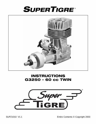
SUPERTIGRE
INSTRUCTIONSG3250 – 60 cc TWIN
Entire Contents © Copyright 2003SUPZ1010 V1.1
®
®

Important: Please read and follow this instruction manual beforeoperating your engine. These instructions have been written sothat you may get the greatest satisfaction from the operation ofyour SuperTigre engine. All SuperTigre engines are designed foroutstanding performance, and are manufactured with the latestcomputer-controlled machinery to insure their high quality.SuperTigre engines have appeared worldwide in competitionsfrom local club events all the way up to World Championshipcompetition.
Crankshaft: The crankshaft transforms the reciprocatingmotion of the piston into rotational motion. The propeller ismounted on the portion of the crankshaft protruding from thecrankcase. The portion of the crankshaft protruding past thedrive washer is known as the “prop shaft.”
Parts Of The Engine
2

Propeller Nut: The propeller nut secures the propeller to thecrankshaft.
Propeller Washer: The propeller washer provides a larger,stronger, surface area to apply pressure to the propeller.
Drive Washer: The drive washer is secured to the crankshaftwith a lock cone and is knurled on one face to provide anon-slip contact surface for the propeller.
Carburetor: The carburetor controls the amount of fuel andair that enters the engine.
Crankcase: The crankcase is the main body of the enginethat houses the internal parts.
Cylinder Head: The cylinder head is mounted on top of thecrankcase. It provides a seal at the top of the cylinder. Thefins on the cylinder head provide a cooling surface. Thecylinder head also holds the glow plug.
Glow Plug: The glow plug provides the heat needed to ignitethe fuel in the cylinder.
Exhaust Manifold: The exhaust manifold allows theadjustment of the distance from the muffler to the engine.
Muffler: The muffler quiets and directs the exhaust after itexits the cylinder.
Pressure Fitting: A tube is connected from the pressurefitting to the fuel tank. When the engine is running, pressurefrom the muffler is used to pressurize the fuel tank.
3

High-Speed Needle: The high-speed needle controls theamount of fuel entering the carburetor during medium andhigh speed operation.
Idle Mixture Screw: The idle mixture screw controls theamount of fuel entering the carburetor while the engineis idling.
Idle Stop Screw: The idle stop screw controls how far thethrottle barrel closes. We suggest that it be set to allow thethrottle barrel to close completely to enable stopping theengine by the throttle trim on the transmitter.
Throttle Arm: The throttle arm is connected to the carburetorbarrel. By moving the throttle arm, the barrel is opened andclosed. This regulates the speed of the engine.
Parts Of The Carburetor
4

Insert the carburetor retaining bolt (the bolt has a curved arearemoved from its center) into the hole in front of thecarburetor opening. Rotate the retaining bolt so that theremoved area in the bolt matches the curve of the carburetoropening. Install the split washer and the brass nut on thethreaded end of the bolt. Insert the carburetor in thecarburetor opening and press down on the carburetor whiletightening the nut.
Carburetor Installation
5

If the G3250 engine is to be mounted on the radial mountprovided with the engine, remove the four screws holding thebackplate. Remove the rubber O-ring on the backplate andinstall it on the radial mount. Attach the radial mount to theengine using the four longer screws and split washersprovided. Install the radial mount to the firewall of the airplanewith three 8-32 screws, three split washers and three blindnuts. (Not Included.)
If the engine is to be mounted on wood beams built into theairplane, the beams must be rigid, parallel with each other,and the top surfaces in the same plane.
Engine Installation
6

Set the engine on the beams atthe correct angle to thecenterline of the fuselage,according to the instructionsprovided by the airplanemanufacturer.
When the engine is mounted in the upright position, thecenterline of the fuel tank should be at the same level as the
7

high-speed needle, or no more than 3/8" lower, to insureproper fuel flow. When the engine is mounted on its side, thecenterline of the fuel tank should be at the same level as thecenter of the intake in the carburetor, or no more than 3/8"lower, to insure proper fuel flow. Mark on the beam thelocations of the four mounting holes. If mounting the engineon wooden beams, drill four 11/64" holes through the beamsperpendicular to the top surface of the beams. Secure theengine to the beams with 8-32 screws, flat washers, lockwashers and 8-32 Nylock nuts or 8-32 blind nuts.
If mounting the engine on a metal or fiberglass engine mount,drill and tap the engine mount to accept 8-32 screws and lockwashers installed through the engine mounting flanges andinto the engine mount.
Note: Some airplane kits require a slight amount of “rightthrust.” This is done by angling the engine to the right tocounteract the torque factor of the propeller. Follow the kitmanufacturer’s instructions to incorporate the correct amountof right thrust, if required.
8

Use two 4mm x 10mm size screws and split washers toattach the exhaust manifold to the engine. Make sure toinstall the gasket between the manifold and the engine andtighten the screws securely.
Install the 5mm x 30mm screw, split washer and 5mm nut inthe muffler, but do not tighten. Slide the muffler over the
Muffler Installation
9

exhaust manifold and position it so that it does not touch thefuselage. Also, to reduce drag it is best to position the mufflerparallel to the fuselage. When the muffler is positionedcorrectly, tighten the 5mm x 30mm screw to clamp the mufflerover the exhaust manifold.
For the engine to operate properly at any attitude, thecarburetor requires constant fuel pressure. When the engineis running, pressure is created in the muffler by the exhaust.Some of this pressure is used to pressurize the fuel tank.Thispressure is provided by a tube from a pressure fitting on themuffler to the vent tube in the fuel tank. Although notabsolutely necessary, pressurizing the fuel tank with mufflerpressure will provide more consistent running, and will helpto maintain more consistent fuel flow during maneuvers. Toinstall the pressure fitting, install the gasket washer on the
Pressure Line Installation
10
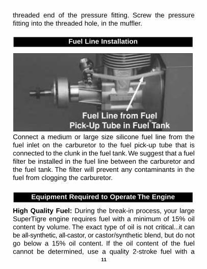
threaded end of the pressure fitting. Screw the pressurefitting into the threaded hole, in the muffler.
Connect a medium or large size silicone fuel line from thefuel inlet on the carburetor to the fuel pick-up tube that isconnected to the clunk in the fuel tank. We suggest that a fuelfilter be installed in the fuel line between the carburetor andthe fuel tank. The filter will prevent any contaminants in thefuel from clogging the carburetor.
High Quality Fuel: During the break-in process, your largeSuperTigre engine requires fuel with a minimum of 15% oilcontent by volume. The exact type of oil is not critical...it canbe all-synthetic, all-castor, or castor/synthetic blend, but do notgo below a 15% oil content. If the oil content of the fuelcannot be determined, use a quality 2-stroke fuel with a
Equipment Required to Operate The Engine
Fuel Line Installation
11

nitromethane content of 5%-10%. The break-in fuel must beused until the engine is well broken-in. Since an engine willbreak-in over the first few gallons of fuel, run your engine onthe 15% oil fuel for at least two gallons’ worth.
After the engine is broken-in with 2 gallons of fuel containing15% oil, you can use a fuel that has as low as 10% to 12%oil content by volume. The oil can be all-castor, all-synthetic,or a castor/synthetic blend. Many fuels blended as “Super-T”,“S.T.” or “SuperTigre” fuels are fuels with low oil content. Becareful in selecting your fuel. Some fuels contain less than10% oil. You must be careful setting the high-speed needlewhen you use fuels with low oil content, because there is lessmargin for error if you get a slightly-lean run. Nitromethanecontent can be 5% to 10%, but 15% can be used if attentionis paid to the high-speed needle setting so that the enginewill not detonate.
Do not use fuel with low oil content for break-in running!If you use a fuel with low oil content for break-in running,there’s a good chance that the connecting rod will seize to thecrankshaft from lack of sufficient lubrication. This will almostalways require replacement of the connecting rod andcrankshaft, which is not a warranty repair.
Propeller: Choose a propeller for initial running from thepropeller chart under the heading “break-in prop sizes.” Afterthe engine has been broken in, you can use that propeller forflying, or choose one of the propellers on the chart listedunder “recommended prop range.”
12

In the case of all of the large SuperTigre engines, peak RPMis what determines the propeller you should use. Theseengines usually run best when peak RPM is limited tobetween 7,300 and 7,800 RPM. These RPM figures are takenwith the engine running at full throttle, on the ground.
Any propeller which gives you the desired static RPM andalso gives you the flight performance you want from yourairplane is a correct propeller. As a rule, lower-pitched propsgive you better takeoff acceleration and climb, while higher-pitched props will give you higher aircraft speed in the air.Youwant to select a prop that gives you the best compromisebetween takeoff, climb, and airspeed. The prop chart givessome props that have worked out for most modelers.
Adjustable Wrench or Open-End Wrench: A wrench will berequired to install and remove the propeller nut.
Starter Stick or Electric Starter: Again, if a 12V battery isused, we recommend an electric starter. If you do not have a12V battery, a starter stick can be used to flip the propeller tostart the engine. Caution: Never use your finger to flip thepropeller. If the engine should backfire, the propeller couldinjure your finger.
Fuel Pump: We recommend an electric fuel pump, operatedfrom a 12V battery, for transferring fuel from the storagecontainer to the aircraft fuel tank. If you do not have a 12Vbattery, we recommend a hand operated fuel pump.
13

Glow Plug Battery: For safety and ease of operation, werecommend a Ni-starter with a self-contained battery. If usinga locking glow plug clip connected to a power panel on a fieldbox, make sure the wires are behind the propeller whenstarting the engine.
Glow Plug: A general-purpose R/C long glow plug in yourSuperTigre engine will work just fine in most cases.
Glow Plug Wrench: The glow plug will eventually fail toretain heat or it will need to be removed to clear a floodedengine. We recommend a 4-way wrench that can be used toremove the glow plug.
Your SuperTigre engine is a two-stroke engine that works ona semi-diesel principle. The fuel is a mixture of methanol,castor or synthetic oil, and nitromethane. This fuel is ignitedin the engine by a combination of compression heating andthe catalytic action of the glow plug. The glow plug must beinitially heated by using a glow plug battery, which isdisconnected once the engine is running. The glow plugrequires 1.2-1.5 volts to glow properly. There are many glowplug batteries and connectors on the market that will do theproper job of heating the glow plug. Once the engine isstarted, the heat of combustion will keep the glow plug hot.Your SuperTigre engine uses a piston ring. The break-inprocess is critical in getting the parts to “wear in” and fitproperly so that the engine will develop proper performanceand useful life.
General Information
14

Check your glow plug by briefly attaching the glow plug batteryto the plug. The plug must glow brightly.
1. To install the glow plug in the engine, first slide thecompression washer onto the glow plug. Carefully screw theglow plug into the top of the cylinder head with your fingers.Tighten the glow plug “finger-tight,” then use a glow plugwrench to tighten the glow plug securely. Do not overtighten theglow plug or the threads in the cylinder head may strip.
2. Locate the correct propeller for your airplane from thepropeller chart on page 18. Ream the propeller hole to theappropriate diameter using a prop reamer. Balance yourpropeller using a prop balancer. To install the propeller on theengine, remove the propeller nut and propeller washer. Ifinstalling a spinner, install the spinner backplate first, followingthe manufacturer’s instructions. Trim the spinner cone as
Initial Setup
15

16
Engine Troubleshooting Diagram

17
Engine Troubleshooting Diagram

necessary so the propeller does not touch the cone. Have atleast 1/16" of space between the propeller blade and spinnercone. Next, install the propeller with the rounded surface of thepropeller blade facing forward. Install the flat side of thepropeller washer against the propeller. Thread the propeller nutagainst the propeller washer, but do not tighten it. Rotate thecrankshaft of the engine counterclockwise to the compressionstroke (the crankshaft will become difficult to turn).
Continue rotating the propeller until it’s at the 2 o’clock position,then tighten the propeller nut securely against the propellerwasher. Some people use a 4-way wrench for this purpose, butit is difficult to get the nut tight enough with that type of wrench.Many modelers use (and we recommend) a 6-inch adjustablewrench for tightening prop nuts.
Propeller Chart
18
Engine
G3250G450060 cc Twin
Break-inProp Sizes
18x1020x822x10
Recommended Prop Range
18x8, 18x10, 20x6, 20x820x8, 20x10, 22x822x10, 24x8

3. Fill the fuel tank by removing the fuel line from the fuel inleton the carburetor, and connecting it to the fuel tubing fromthe fuel pump. Remove the pressure line from the pressurefitting on the muffler and direct this fuel into an “overflowbottle.” Start filling the fuel tank. When the tank is full, fuel willoverflow out of the pressure line. Disconnect the fuel pumpfrom the fuel line and reconnect it to the carburetor.Reconnect the pressure line to the muffler pressure fitting.
19

4. Gently turn the high-speed needle valve clockwise until itstops. Do not tighten it. Then open it 4 turns. Turning the high-speed needle in a clockwise direction is called “leaning” themixture, and turning it counterclockwise is called “richening”the mixture.
Do not worry about the setting of the idle mixture screw atthis time. It has been set close to the proper setting by thefactory.
20

CAUTION: When running the engine make sure you haveplenty of ventilation. Model exhaust fumes are just as deadlyas automobile fumes. Wear hearing protection when you’reoperating your engine – the noise is very loud.
5. Switch on the transmitter, then receiver. Fully open thethrottle. Do not attach the starting battery at this time. Placea finger over the carburetor intake and turn the propeller overseveral times (counterclockwise). Watch the fuel line. You willsee the fuel come up to the carburetor. Once the fuel reachesthe carburetor, turn the engine two more revolutions. Removeyour finger from the carburetor intake, and briskly flip thepropeller to work the fuel into the cylinder. This process iscalled “choking” the engine.
Have an assistant hold the airplane securely from behind thewing to prevent the airplane from moving forward.You will seesome modelers starting their engine with one hand while
Initial Running and Break-In
21

holding their airplane with the other. This is an unsafe practicethat greatly increases the chances of having an accident.
Close the throttle to about 1/4-1/3 open.
Securely attach the glow plug clip to the glow plug. If using aglow plug clip connected to the power panel of a field box,
22
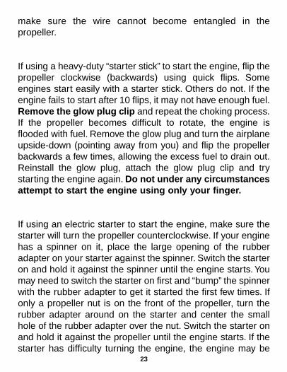
make sure the wire cannot become entangled in thepropeller.
If using a heavy-duty “starter stick” to start the engine, flip thepropeller clockwise (backwards) using quick flips. Someengines start easily with a starter stick. Others do not. If theengine fails to start after 10 flips, it may not have enough fuel.Remove the glow plug clip and repeat the choking process.If the propeller becomes difficult to rotate, the engine isflooded with fuel. Remove the glow plug and turn the airplaneupside-down (pointing away from you) and flip the propellerbackwards a few times, allowing the excess fuel to drain out.Reinstall the glow plug, attach the glow plug clip and trystarting the engine again. Do not under any circumstancesattempt to start the engine using only your finger.
If using an electric starter to start the engine, make sure thestarter will turn the propeller counterclockwise. If your enginehas a spinner on it, place the large opening of the rubberadapter on your starter against the spinner. Switch the starteron and hold it against the spinner until the engine starts. Youmay need to switch the starter on first and “bump” the spinnerwith the rubber adapter to get it started the first few times. Ifonly a propeller nut is on the front of the propeller, turn therubber adapter around on the starter and center the smallhole of the rubber adapter over the nut. Switch the starter onand hold it against the propeller until the engine starts. If thestarter has difficulty turning the engine, the engine may be
23

flooded with fuel. Clear the engine of fuel as describedabove. Do not continue to try starting a flooded engine. Theconnecting rod in the engine could be damaged.
The engine should start and keep running, although it may berunning slightly rough at this time. This is normal. Allow theengine to warm up for 15 to 20 seconds before removing theglow plug clip. Let the engine run at this throttle setting for 30seconds and then open the throttle to full.
The engine should be running at full-throttle, but be runningsomewhat rough, with a lot of fuel/oil being discharged fromthe exhaust port. This is because the engine is running in avery rich condition...that is, more fuel is running through theengine than is needed. Run the engine at this setting.
After ten to fifteen minutes, you can start leaning the engineby turning the high-speed needle clockwise. Never turn theneedle more than 1/8 of a turn at this point. To determine ifthe engine will accept having the needle leaned, give the fuelline a quick pinch and release...just pinch the fuel line and letgo. You should hear the engine increase a bit in RPM, withthe sound going up in pitch. If the engine increases in RPM,you can lean 1/8 of a turn. Allow the engine to run for severalminutes at this setting. Now give the fuel line a quick pinchand release. Wait a minute and do it again. Do this five times.If the RPM increases all five times, lean the high-speedneedle another 1/8 of a turn. Wait one minute, and then startthe pinch and release series again. If the engine doesn’tincrease in RPM when you pinch and release, wait one
24
minute before you try the pinch and release series again.Don’t lean the high-speed needle until you get an increase inRPM every time you pinch and release the fuel line.
Keep repeating the “pinch and release” method until the RPMdoes not change when you pinch the line. At this point, you’veleaned the engine as far as possible. Do not ever lean theengine to the point that the RPM decreases when you pinchthe line. For flying, you want to set the high-speed needle sothat you get an increase in RPM when you pinch the fuel lineor when you point the nose of your model straight up.
If you hear the engine’s RPM decrease when you pinch andrelease, you must immediately turn the high-speed needlecounterclockwise at least 1/2 turn. The drop in RPM tells youthat the engine is too lean, and needs to be run at a richersetting for at least a few more minutes. Don’t be in a hurry tolean your engine to peak RPM. Be conservative, and takeyour time. Running richer longer will not hurt your engine abit. You may have to spend an hour running your engine onthe ground before you can fly it. A careful, conservative break-in will only insure a good, long useful life for your engine.
The idle mixture is adjusted with the brass screw that’slocated in the center of the throttle arm. It operates in thesame manner as the high-speed needle; turning it clockwiseleans the idle mixture, and turning it counterclockwiserichens the idle mixture.
Idle Mixture Setting
25

The basic adjustment of the idle mixture screw has been setby the factory, and should require little adjustment, if any. Usethe same “pinch and release” method to determine if the idlemixture is rich or lean. You may have to hold the pinch a bitlonger than when the engine was running at high speedbecause fuel flow is slower at low throttle settings.
The best way to adjust the idle mixture is to have the enginerunning at full-throttle, and slowly close the throttle. Once theengine has been throttled back to below 1/2 throttle, try thepinch and release method. The engine should increase inRPM slightly. This means that you can lean the idle mixture abit, about 1/8 turn. Reduce the throttle a little more, andrepeat. You should be able to work your way down to a nice,low idle. The carburetor barrel will be open about 1/32" to1/16" when the engine is idling properly.
To stop the engine before it runs out of fuel, we suggest thatthe radio be set up so that when the transmitter throttle and
Stopping & Restarting The Engine
26

throttle trim are moved to the low position, the carburetor iscompletely closed. If your throttle was not set up this way,pinch the fuel line from the fuel tank to the carburetor andhold it until the engine stops.
Restarting the EngineIf the engine is still warm, try to start the engine withoutchoking it first. If the engine has cooled down it may need tobe choked.
If the engine does not start after choking, the engine may beflooded. Clear the excess fuel from the engine as describedearlier. Attach the glow plug clip to the glow plug and checkthat it glows bright orange. If it does, reinstall it in the engine.If it does not, replace the glow plug with a new one. Try torestart the engine without choking it.
Engine won’t fire: Check to make sure the glow plug isglowing brightly. Make sure the engine is getting sufficient fuel.Make sure the engine isn’t flooded.
Engine fires, but runs only for a brief time: The engine isn’tgetting enough fuel. Open the high-speed needle 1/4-1/2 turn.You may have to choke the engine again. Check for kinks inthe fuel line.
Engine only “pops” and sputters: The engine is flooded.Remove the glow plug and turn the airplane upside-down(pointing away from you), and flip the propeller backwards a
Troubleshooting
27

few times, allowing the excess fuel to drain out. Reinstall theglow plug.
Engine fires and runs at a very high speed: The high-speedneedle may be too lean. Open it at least 1/2 turn. The fuel linemay have an air leak (especially if the engine will not respondto opening the high-speed needle). The muffler pressure linemay have come off of the muffler or the fuel tank. The fuel lineis too small in diameter.
Engine runs for a few minutes and then quits: The high-speed needle may be too lean. Open it at least 1/2 turn. Thefuel tank may be too low. The fuel line may have a kink or anair leak. The propeller may be too large. The fuel is deficient inoil content. The engine isn’t getting enough cooling air.
When it’s been properly broken-in, your SuperTigre engineshould give you many years of reliable service. To make sureit lasts as long as possible, there are a few things you can doto care for it.
• At the end of every flying session, drain the fuel tankcompletely. Then remove the fuel line from the engine, andattempt to start it. It should start and then run for a shortperiod. Keep trying to start the engine until it just won’t fire.You want the engine “dry” of fuel.
• After the engine is dry of fuel, open the throttle to “full” andput several drops of a good-quality “after-run oil” into the
Care And Maintenance
28

engine. Don’t have the glow plug clip attached while doing this.Briskly hand-flip the engine, as if you were trying to start it, tomake sure the oil is worked into the engine. Repeat theprocess. Be liberal with the oil.You want to make sure all of theinternal parts get well-coated. Several manufacturers makespecific after-run products to protect your engine betweenflying sessions. We don’t recommend that you use any kind ofwater dispersant or penetrating oil in your SuperTigre engine.These kinds of oil will loosen any rust and allow it to bedispersed throughout the engine the next time it’s run. Rust isiron oxide, which is an abrasive compound. If it is allowed torun through the engine, the parts will lose their properclearances and performance will be lost.
• For long-term storage, remove the engine from the modeland be extremely generous in getting all of the engine partscoated with the after-run oil. Wrap the engine in a plastic bagto keep out moisture and to prevent the oil from drying out.
• Keep your engine clean. Wipe off the outside of the enginewith denatured or rubbing alcohol to remove any fuel residueand dirt. If dirt or burned-on fuel residue is allowed toaccumulate on the cylinder fins, the engine’s cooling abilitywill be reduced. The dirt or burned-on residue will act as aninsulating blanket and prevent proper cooling. This isespecially critical in cowled installations. Dirt will also abradethe moving parts if it’s allowed to get inside the engine.
• We suggest that a fuel filter be installed between thecarburetor and the fuel tank to prevent dirt from entering thecarburetor.
29

• Do not disassemble the engine unless you are a qualified todo so.
• Avoid running the engine in dusty conditions. If the area youfly in is dusty, such as a dirt runway, we suggest installing anair filter made for airplane engines.
• After flying, check all engine mounting bolts, muffler screws,propeller nut and spinner to make sure they have notloosened up.
1. Keep all spectators at least 20 feet away whenoperating the engine.
2. Keep yourself out of the path of the prop. Do not leanover the propeller when starting or adjusting the engine.
3. Always balance the propeller before installing it on theengine. Never use a propeller that is damaged, nomatter how slight.
Powerful engines can spin propeller tips at speeds ofover 600 feet (180 meters) per second. Be aware thatloose or damaged propellers can cause serious harm ifthey are thrown off.
4. Make sure the edges of the spinner do not touch thepropeller blades. The sharp edges may cut into thepropeller blades and cause them to break.
Safety Precautions and Warnings
30

5. Be sure your glow plug clip cord will not interfere withthe propeller when it’s turning.
6. Never use your finger to start the engine. Always use a“starter stick” or electric starter.
7. Make all engine adjustments from behind the propeller.Always stop the engine before adjusting the idle stopscrew or idle mixture screw.
8. Do not operate the engine in an area with loose gravelor sand.
9. Wear safety glasses or goggles when starting andrunning the engine.
10. Keep all loose clothing such as neck ties and shirtsleeves away from the propeller. Remove any objectsfrom your shirt pockets to prevent them from falling intothe propeller.
11. Keep model engine fuel away from your eyes andmouth, as it is highly poisonous. Store the fuel in aclearly labeled container far from the reach of children.
12. Keep all model fuel away from children, sparks andexcessive heat. Do not smoke while handling modelfuel. Model fuel is highly flammable and must behandled with caution. Model fuel must be stored in acool, dark place, and kept tightly sealed. Thetemperature of the storage area must be fairly stable.Moisture will ruin model fuel.
31

13. Never operate the model engine in an enclosed area.The engine produces deadly carbon monoxide andmust be run in a well ventilated area, outdoors.
14. Model engines get very hot when running. Do not touchany part of the engine until it cools. Considerable heatis quickly produced by a running model engine. If youtouch any part of the engine (especially themuffler/silencer, cylinder head, or exhaust header), youcould be seriously burned. Avoid contact until theengine cools.
The warranty of your SuperTigre engine is detailed on a separate insert. Forall repairs, warranty or non-warranty, your engine can be sent to:
Hobby Services3002 N. Apollo Dr., Suite 1Champaign, IL 61822Phone: (217) 398-0007e-mail: [email protected]
9:00 A.M. to 5:00 P.M. Central timeMonday through Friday
Contact Hobby Services for engine repair information only. For questionsregarding engine setup or operation please contact Product Support at:
Phone: (217) 398-8970e-mail: [email protected]
If you need information to send your engine in for service, please visitwww.hobbyservices.com for all the information you need.
Repairs