Embed Size (px)
Citation preview
Supplementary Information
Planning Act 2008 Infrastructure Planning The Infrastructure Planning (Applications: Prescribed Forms and Procedure) Regulations 2009 Section Number: 51 Author: A30 Temple to Higher Carblake Improvement
Team, Cornwall Council Document Reference:
TRXCP311/PA/SI/03
PI Reference TR010014 Document Date Version Note 08 January 2014 0 First Issue
Supplementary Information
Issue & Revision Record Revision Date Author Purpose of Issue / Nature of
Change 0 27/09/13 AH First Draft Issue 1 08/01/14 AH Final Draft Issue 2 08/01/14 AH/EM Final for Issue
This document has been prepared for the titled project or named part thereof and should not be relied upon or used for any other project without an independent check being carried out as to its suitability and prior written authority of Cornwall Council being obtained. Cornwall Council accepts no responsibility or liability for the consequences of this document being used for a purpose other than the purposes for which it was commissioned. Any person using or relying on the document for such other purposes agrees, and will by such use or reliance be taken to confirm his agreement to indemnify Cornwall Council for all loss or damage resulting therefrom. Cornwall Council accepts no responsibility or liability for this document to any party other than the person by whom it was commissioned.
Cornwall Council A30 Temple to Higher Carblake Improvement Transportation Services Application for Development Consent Order Document Reference: TRXCP311_PA_SI_03
Supplementary Information 1
CONTENTS Page
1 INTRODUCTION 3
2 ENVIRONMENTAL STATEMENT TEXT 3
2.1 Project Description 3
2.2 Landscape And Visual Effects 10
2.3 Public Rights Of Way 10
2.4 Private Accesses 11
2.5 Drawing Scales 16
2.6 Limits Of Deviation 17
2.7 Earthworks Design Principles 17
3 ENVIRONMENTAL STATEMENT FIGURES 23
4. ADDITIONAL INFORMATION 25
4.1 Appendices 25
4.2 National Networks National Policy Statement 25 Appendix A List of Figures Appendix B Ground Investigation Report and Geotechnical
Design Report Appendix C Design Options Report
Cornwall Council A30 Temple to Higher Carblake Improvement Transportation Services Application for Development Consent Order Document Reference: TRXCP311_PA_SI_03
Supplementary Information 2
GLOSSARY AND ABBREVIATIONS
Area of Outstanding Natural Beauty AONB Statutory designation which confers the means to protect the most important landscape of England and Wales for the benefit of future generations.
Area of Great Landscape Value AGLV Landscapes of local importance.
Cornwall Council CC The applicant.
Development Consent Order DCO Order under which the relevant Secretary of State can grant consent for construction of a Nationally Significant Infrastructure Project, on the advice of the Planning Inspectorate, under the Planning Act 2008 (as amended by the Localism Act).
Environmental Impact Assessment EIA Under the Infrastructure Planning (Environmental Impact Assessment) Regulations 2009 as amended, proposers of certain scheduled developments are required to submit a planning application with an accompanying environmental statement, evaluating the likely environmental impacts of the development, together with an assessment of how the severity of the impacts could be reduced.
Environmental Statement ES The report on the results of an EIA.
Ground Investigation Report GIR The report on the results of ground investigations.
Geotechnical Design Report GDR An interpretive report using the findings of a GIR to provide the parameters for design.
Planning Inspectorate PINS
Section 51 of the Planning Act 2008 The Secretary of State may give advice to an applicant or potential applicant, or to others, about- (a) applying for an order granting development consent; (b) making representations about an application, or a proposed application, for such an order.
Section 55 of the Planning Act 2008 The Secretary of State must, by the end of the period of 28 days beginning with the day after the day on which it receives the application, decide whether or not to accept the application. This Section also sets out what should be taken into account when reaching that decision.
Cornwall Council A30 Temple to Higher Carblake Improvement Transportation Services Application for Development Consent Order Document Reference: TRXCP311_PA_SI_03
Supplementary Information 3
1 INTRODUCTION
1.1.1 On 9th September 2013, the Cornwall Council (CC) as the Applicant received a letter from the Planning Inspectorate (PINS) confirming that the application by Cornwall Council for an Order granting Development Consent for the A30 Temple to Higher Carblake Improvement Scheme had been accepted for examination under S55 of the Planning Act 2008 as amended. The letter enclosed a copy of the checklist which PINS completed in order to assess the acceptability of the application (the ‘S55 Checklist’).
1.1.2 On 13th September 2013, the Applicant also received a letter from PINS providing advice under S51 of the Planning Act 2008. This letter advised the Applicant that certain parts of the application documents, including the Environmental Statement, would benefit from further explanation.
1.1.3 This Supplementary Information document provides a response to the comments raised in the S51 advice letter and S55 Checklist where appropriate.
2 ENVIRONMENTAL STATEMENT TEXT
2.1. Project Description
2.1.1 Page 1 of the S51 advice letter and Part 4.4(a) of the S.55 Checklist state that further information on the dimensions of the different elements of the proposed Scheme should be provided to ensure clarity as to the extent of matters assessed in the ES. In particular, PINS requested further information on the vertical alignment of the different elements of the proposed Scheme.
2.1.2 The following paragraphs provide this information. They supplement paragraphs 2.3.38 and 2.3.39 of the Environmental Statement (ES) and provide further information on the vertical alignment of the Scheme.
Main Alignment - Vertical
2.1.3 The vertical alignment for the proposed Scheme has been designed from a central point between the proposed eastbound and westbound carriageways, with the exception of
Cornwall Council A30 Temple to Higher Carblake Improvement Transportation Services Application for Development Consent Order Document Reference: TRXCP311_PA_SI_03
Supplementary Information 4
a split level carriageway from chainage 0 to 600. Chainages on the main alignment can be seen on the following Figures: Figure 08.06.01A (chainage 0-800), Figure 08.06.02A (chainage 900-2000), Figure 08.06.03A (chainage 2100-3300), Figure 08.06.04A (chainage 3400-4800), Figure 08.06.05A (chainage 4900-5000). These drawings replace those in the original ES and have been updated to show further detail.
2.1.4 The concept for the vertical design has been to follow the alignment of the existing carriageway as closely as practicable to provide an economically viable and environmentally sensitive design solution. This has ensured that the footprint of the Scheme is kept to a minimum and, where practical, within the existing highway boundary. It has also minimised areas of new cut or fill by widening into existing cuttings or extending existing embankments. Long sections for the main alignment are shown on Figures 02.02.01 to 02.02.02, which were not originally in the ES and have been prepared to provide more detail.
2.1.5 The proposed vertical alignment for the carriageway follows the natural topography of the landscape with three existing low points located at chainages 900, 2000 and 4500. These points also form the location for attenuation and outfall for the proposed highway drainage.
2.1.6 In the main, earthwork slopes have been designed at a maximum gradient of 1:1.5 to minimise the footprint of the proposed Scheme. This design approach has been supported in Sections 1.1 and 1.2 of the Geotechnical Design Report (document reference 63548/GDR) in Appendix B. Where it is proposed that land is returned to landowners and previous use or where there is a need to regrade the embankments for environmental or aesthetic purposes, proposed embankment slopes have been designed at shallower gradients.
2.1.7 The description of the vertical design for the Scheme is detailed below. The sections of proposed A30 embankments and depths of proposed cuttings are described from main alignment chainages and give dimensions to the nearest metre.
2.1.8 Typical cross-sections for the proposed Scheme are shown on Figures 08.06.06A to 08A and 08.06.09. The locations of the
Cornwall Council A30 Temple to Higher Carblake Improvement Transportation Services Application for Development Consent Order Document Reference: TRXCP311_PA_SI_03
Supplementary Information 5
proposed cross-sections are shown on Figures 08.06.01-05 rev A. These drawings replace those in the ES and have been updated to provide more detail.
Westbound
2.1.9 As a result of widening on the south eastern side of the existing carriageway where landform predominantly falls away from the existing level of the carriageway, an embankment of maximum 2m height at a gradient of 1:1.5 will be formed between chainages 750 and 1225.
2.1.10 The Scheme then widens out into an existing cutting at the proposed location of Preeze Cross overbridge between chainages 1350 and 1680 with 1:1.5 cutting slopes of 4m maximum height and a retaining wall positioned between chainages 1460 and 1520.
2.1.11 Between chainages 1750 and 2150 the existing carriageway lies above existing ground level and as a result the widening on the south eastern side of the proposed carriageway creates a 1:1.5 embankment with a maximum height of 3m. The Scheme then widens out into an existing 1:1.5 cutting of 3m height between chainage 2400 and 2550. A further cutting of 3m depth is formed between chainage 2760 and 2940. This slope has been designed at a gradient of 1:1 to maintain the footprint of the Scheme within the existing highway boundary and reduce required landtake within Cardinham Moor Common Land.
2.1.12 The remaining westbound vertical alignment ties into the existing ground level with the exception of an embankment of 2m height between chainage 3150 and 3350. This embankment has been designed at 1:1.5 but will require a shorter, steeper section at 1:1.2 between chainage 3210 and 3290 to enable the footprint of the design to tie into the existing land boundary and avoid additional land take from Cardinham Common Land. A further embankment is formed at a gradient of 1:1.5 and height of 2.5m between chainage 4300 and 4480 where edge widening is required.
Eastbound
Cornwall Council A30 Temple to Higher Carblake Improvement Transportation Services Application for Development Consent Order Document Reference: TRXCP311_PA_SI_03
Supplementary Information 6
2.1.13 The split level dual carriageway on the eastbound side cuts into existing ground up to a maximum depth of 2m between chainage 150 and 400.
2.1.14 The proposed main alignment then ties into existing ground level between chainage 400 and 1900. The level of the proposed carriageway is raised from existing between chainage 1900 and 2600 by 2m and is extended to the north to provide the Trethorne access road which sits, at its highest point, 1.5m above existing ground level. An embankment is proposed over this section at maximum 2m height and at a gradient of 1:1.5.
2.1.15 The proposed Scheme then widens into an existing cutting up to 2.5m maximum height between chainage 3420 to 3560. This section of cut will be made within a section of competent granite and, as a result, has been designed at a gradient of 1:1 to minimise the footprint of the scheme. Between chainage 3750 and 3970 a 1 in 4 cutting is proposed at the location of an existing cutting of steeper gradient at 2m height. This has been designed at a shallower gradient to enable the embankment to be returned as Greenbarrow Common Land. The Scheme then widens into an existing cutting of 4m in height between chainage 3970 and 4250 at a gradient of 1:1.5.
2.1.16 Continuing on the eastbound side, between chainage 4275 and 4500, an embankment of maximum 4m height is formed at a gradient of 1:1.5 where the carriageway widens out into an area of land which currently falls away to the north. From chainage 4750 to 5000, an existing embankment of maximum 2m height is extended to the north at a gradient of 1:1.5 to accommodate the widening of the carriageway.
2.1.17 The following paragraphs supplement paragraphs 2.3.12 and 2.3.17 of the ES.
Compact Loop Junctions – Vertical alignment
2.1.18 The main concept behind compact grade separated junctions is to provide a junction design with a reduced footprint, thereby minimising environmental effects and associated costs. This form of junction benefits from a reduction in approach loop or link roads which traditionally require large
Cornwall Council A30 Temple to Higher Carblake Improvement Transportation Services Application for Development Consent Order Document Reference: TRXCP311_PA_SI_03
Supplementary Information 7
footprint and land take with standard grade separated junctions.
2.1.19 The vertical alignment for Cardinham Downs compact junction is shown in Figure 02.02.03. Preeze Cross vertical alignment is shown in Figure 02.02.04. Temple Tor vertical alignment is shown in figure 02.02.06. This drawing was not originally in the ES and has been prepared to provide more detail.
2.1.20 Cross-sections for the proposed link roads are shown in Figure 08.06.09. A plan view of Cardinham Downs is shown on Figure 08.06.01A, Preeze Cross is shown on Figure 08.06.02A and Temple Tor is shown on Figure 08.06.04A. These drawings replace those in the original ES and have been updated to provide more detail.
Cardinham Downs
2.1.21 At Cardinham Downs junction the existing landform rises to the south east of the Scheme resulting in a proposed cutting on the westbound side of the A30, 4m below existing ground level and designed at a gradient of 1:1.5 to minimise land take. To the north the land falls away creating the need for an embankment 10m above existing ground level. This embankment has been designed at a gradient of 1:1.5 with the exception of the north east section which will be returned to the original land owner. In order to allow practical future use of this section of the embankment, it has been designed at a gradient of 1 in 3. The maximum height of the proposed overbridge parapet at Cardinham Downs is 8.1m above the proposed level of the carriageway. This allows for the 5.3m minimum clearance from proposed carriageway level to the soffit of the bridge in line with current design standards.
Preeze Cross
2.1.22 The proposed junction at Preeze Cross ties into the C0034 leading to Tresarett on the north western side of the A30 and into the C0110 leading to Millpool on the south eastern side. The junction arm on the northwest side of the A30 leading to Preeze Cross overbridge follows the existing topography of the landscape, which naturally rises up from west to east and the location of the bridge. As a result, minimal earthworks are required with cuttings and embankments of 2m maximum depth or height. All earthworks on the north western side
Cornwall Council A30 Temple to Higher Carblake Improvement Transportation Services Application for Development Consent Order Document Reference: TRXCP311_PA_SI_03
Supplementary Information 8
have been designed at a gradient of 1:1.5 to reduce permanent landtake.
2.1.23 On the south eastern side, the proposed junction arm follows adjacent to the A30 with maximum depths of cuttings and embankments at 2m height, designed at a gradient of 1 in 1.5. The exception to this is where the topography falls away to the south at the location of the bridge. In order to raise the carriageway to the required level, an embankment height of 3m is required on the south eastern side for 100m. The highway boundary will be formed at the top of this proposed embankment and the embankment itself will be returned to the landowner. To allow practical future use of the land, this embankment has been designed at a gradient of 1 in 3. The maximum height of the overbridge parapet at this location is 8.3m above the proposed level of the carriageway. This allows for the 5.3m minimum clearance from proposed carriageway level to the soffit of the bridge in line with design standards.
Temple Tor
2.1.24 At Temple Tor, the compact loop junction arms are both located to the south west of the proposed overbridge. In general, the existing carriageway at Temple Tor is built up above the natural landform due to poor site conditions. As a result, both compact loop junction arms require embankments to connect the proposed level of carriageway to the level of the overbridge. A maximum embankment height of 8m is required on both westbound and eastbound sides of the proposed A30. Gradients of the proposed embankments vary within the junction. The area of land inside the northern loop will be returned to Common Land and as a result the internal embankments have been designed at a gradient of 1:3. Although the external embankments will also be returned to Common Land, it is envisaged that they will be designed to replicate a granite outcrop with embedded boulders, replicating existing outcrops within the area. They have, as a result, been designed at a steeper gradient of 1:1.5. A small section of the southern compact loop embankment will be returned to Common Land and this has been designed at a gradient of 1:3. The remainder of the southern loop embankments will be dedicated as highway land but have also been designed at a gradient of 1:3 in order to minimise the visual impact on the area. The maximum height of the

Cornwall Council A30 Temple to Higher Carblake Improvement Transportation Services Application for Development Consent Order Document Reference: TRXCP311_PA_SI_03
Supplementary Information 9
overbridge parapet at this location is 8.5m above the proposed level of the carriageway. This allows for the 5.3m minimum clearance from proposed carriageway level to the soffit of the bridge in line with design standards.
Materials
2.1.25 The following paragraphs supplement Section 2.3 of the ES and relate particularly to paragraphs 2.3.31 and 2.3.32.
Cardinham Downs Overbridge and Temple Tor Overbridge
2.1.26 Cardinham Downs Overbridge and Temple Tor Overbridge will have two spans of a reinforced concrete over steel beams. These beams are supported by a wall at either end and a rounded concrete column in the middle. The colour of the beams will be a dark yellowy green. The front of the walls will have a concrete surface with a vertical recessed pattern and the sides of the walls will be faced with Cornish grey granite. The colours were chosen to fit with those found on Bodmin Moor.
Preeze Cross Overbridge
2.1.27 Preeze Cross Overbridge will have a single span of reinforced concrete over steel beams. These beams are supported by a wall at either end. The colour of the beams will be a dark yellowy green. The front of the walls will have a concrete surface with a vertical recessed pattern and the sides of the walls will be faced with Cornish grey granite. The colours were chosen to fit with those found on Bodmin Moor.
Preeze Cross Retaining wall
2.1.28 Preeze Cross Retaining Wall is next to Preeze Cross Overbridge and will support land next to the widened A30. The face of the wall will be Cornish grey granite.
Pounds Conce Bat and Otter Culvert
2.1.29 Pounds Conce Bat and Otter Culvert will be under the A30 and the only parts which will be seen are from Bodmin Moor and these are the walls at either end. The face of the walls will be Cornish grey granite.

Cornwall Council A30 Temple to Higher Carblake Improvement Transportation Services Application for Development Consent Order Document Reference: TRXCP311_PA_SI_03
Supplementary Information 10
2.2. Landscape And Visual Effects
2.2.1 Pages 2 and 3 of the S51 advice letter indicated that it was not clear whether appropriate information on the dimensions of the Scheme was available to the consultant undertaking the landscape and visual assessment and therefore PINS could not be satisfied that the guidance for such assessment have been followed.
2.2.2 The information shown in Figures 08.08.01 to 08.08.10 as submitted (see Paragraph 3.1.4 below for explanation of how these Figures have been updated) and in the above paragraphs was available to the consultant who carried out the landscape and visual assessment set out in Chapter 8 of the ES through the application drawings (Document Reference TRXCP311_PA_2.01 to 2.12) and via continuous dialogue with the designers throughout the assessment.
2.2.3 The extent of the highway scheme, its ability to sit within the landscape and its vertical and horizontal alignment was considered in the assessment. These aspects and the size and visibility of key structures as viewed from receptor points in the wider landscape were important considerations in the assessment of the significance of landscape and visual effects.
2.2.4 The depths of the cuttings, slope gradients and heights of the embankments and overbridges were considered, particularly when assessing the impact of the Bodmin Moor Area of Outstanding Natural Beauty and Camel and Allen Valleys Area of Great Landscape Value. The materials to be used were also considered in the assessment and consultant was involved in the process of selecting those materials to ensure that they were compatible with the landscape context.
2.3. Public Rights Of Way
2.3.1 Paragraph 2.3.23 of the ES states:
“The Stokely Farm (FP/503/16 [Blisland Civil Parish]) route that meets and crosses the A30 in the vicinity of Pounds Conce will be shortened to connect into the new side roads and Preeze Cross overbridge. This will require a short length of stopping up and new gates and signs to be installed. The additional diversionary length involved in this adjustment is approximately 480m.”
Cornwall Council A30 Temple to Higher Carblake Improvement Transportation Services Application for Development Consent Order Document Reference: TRXCP311_PA_SI_03
Supplementary Information 11
2.3.2 PINS stated on Page 3 of the Section 51 advice letter that it is not possible to identify from Figure 13.01 of the ES where this diversion is located. It should be noted that this Public Right of Way (PRoW) has been diverted on to a side road and therefore no new PRoW section will be created by this diversion.
2.3.3 The locations of the four alterations to the sections of PRoW that abut the existing A30 are shown in Figure 13.01A and the changes are shown in Figure 13.02 in detail as described in Para.2.3.20 to 2.3.24 of the ES (on page 45 of document reference TRXCP311/PA/6.01).
2.4. Private Accesses
2.4.1 Information on the impacts of the Scheme on private accesses and the alternative arrangements made as a result were presented in the Street Plans (Document Reference TRXCP311_PA_2.04) and within Schedule 5 of the Draft Development Consent Order (Document Reference TRXCP311_PA_3.1) in the original submission.
2.4.2 Figures 13.03.00 to 13.03.10, which are based on the Street Plans, are appended to this document in order to illustrate better the changes proposed to the private accesses in detail in the context of the ES text. Reference to these figures supplements paragraph 13.8.16 to 13.8.22 of the ES
2.4.3 There are a number of private accesses which have direct access to the A30 at present. These accesses will be subject to changes in order to increase safety as show in Figures 13.03.00 to 13.03.10.
2.4.4 The approach taken has been, through consultation with the affected landowners, to close direct private accesses onto the A30 throughout the Scheme, replacing these with alternative accesses which connect into the local and trunk road network via the new and existing side roads, overbridges and junctions.
2.4.5 Where a private access could not be relocated, improvements to the alignment, levels and/or visibility splays have been proposed as an alternative. There are a few limited instances, where an existing access will be closed without provision of an alternative but this only occurs where there is an existing
Cornwall Council A30 Temple to Higher Carblake Improvement Transportation Services Application for Development Consent Order Document Reference: TRXCP311_PA_SI_03
Supplementary Information 12
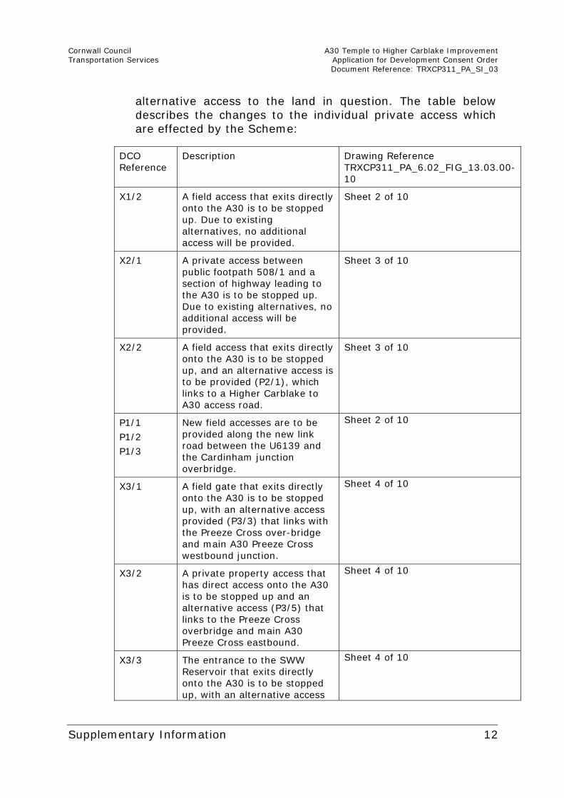
alternative access to the land in question. The table below describes the changes to the individual private access which are effected by the Scheme:
DCO Reference
Description Drawing Reference TRXCP311_PA_6.02_FIG_13.03.00-10
X1/2 A field access that exits directly onto the A30 is to be stopped up. Due to existing alternatives, no additional access will be provided.
Sheet 2 of 10
X2/1 A private access between public footpath 508/1 and a section of highway leading to the A30 is to be stopped up. Due to existing alternatives, no additional access will be provided.
Sheet 3 of 10
X2/2 A field access that exits directly onto the A30 is to be stopped up, and an alternative access is to be provided (P2/1), which links to a Higher Carblake to A30 access road.
Sheet 3 of 10
P1/1
P1/2
P1/3
New field accesses are to be provided along the new link road between the U6139 and the Cardinham junction overbridge.
Sheet 2 of 10
X3/1 A field gate that exits directly onto the A30 is to be stopped up, with an alternative access provided (P3/3) that links with the Preeze Cross over-bridge and main A30 Preeze Cross westbound junction.
Sheet 4 of 10
X3/2 A private property access that has direct access onto the A30 is to be stopped up and an alternative access (P3/5) that links to the Preeze Cross overbridge and main A30 Preeze Cross eastbound.
Sheet 4 of 10
X3/3 The entrance to the SWW Reservoir that exits directly onto the A30 is to be stopped up, with an alternative access
Sheet 4 of 10
Cornwall Council A30 Temple to Higher Carblake Improvement Transportation Services Application for Development Consent Order Document Reference: TRXCP311_PA_SI_03
Supplementary Information 13
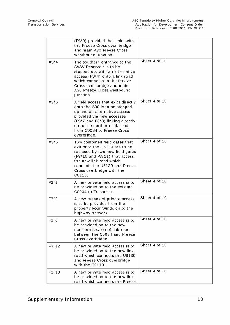
(P3/9) provided that links with the Preeze Cross over-bridge and main A30 Preeze Cross westbound junction.
X3/4 The southern entrance to the SWW Reservoir is to be stopped up, with an alternative access (P3/4) onto a link road which connects to the Preeze Cross over-bridge and main A30 Preeze Cross westbound junction.
Sheet 4 of 10
X3/5 A field access that exits directly onto the A30 is to be stopped up and an alternative access provided via new accesses (P3/7 and P3/8) linking directly on to the northern link road from C0034 to Preeze Cross overbridge.
Sheet 4 of 10
X3/6 Two combined field gates that exit onto the U6139 are to be replaced by two new field gates (P3/10 and P3/11) that access the new link road which connects the U6139 and Preeze Cross overbridge with the C0110.
Sheet 4 of 10
P3/1 A new private field access is to be provided on to the existing C0034 to Tresarrett.
Sheet 4 of 10
P3/2 A new means of private access is to be provided from the property Four Winds on to the highway network.
Sheet 4 of 10
P3/6 A new private field access is to be provided on to the new northern section of link road between the C0034 and Preeze Cross overbridge.
Sheet 4 of 10
P3/12 A new private field access is to be provided on to the new link road which connects the U6139 and Preeze Cross overbridge with the C0110.
Sheet 4 of 10
P3/13 A new private field access is to be provided on to the new link road which connects the Preeze
Sheet 4 of 10

Cornwall Council A30 Temple to Higher Carblake Improvement Transportation Services Application for Development Consent Order Document Reference: TRXCP311_PA_SI_03
Supplementary Information 14
Cross overbridge with Pounds Conce.
P3/14 A new private field access is to be provided on to the new link road which connects the Preeze Cross overbridge with Pounds Conce.
Sheet 4 of 10
P3/15 A new private field access is to be provided on to the improved section of the U6139 leading to Preeze Cross overbridge.
Sheet 4 of 10
X4/1
Field access that exits directly onto the A30 is to be stopped up, with new accesses between the U6139 and proposed attenuation pond to be provided (P4/6, P4/7, P4/8 and P4/9).
Sheet 5 of 10
X4/2
Field access that exits directly onto the A30 is to be stopped up, with new accesses between the U6139 and proposed attenuation pond to be provided (P4/6, P4/7 and P4/11).
Sheet 5 of 10
X4/3
Field access that exits directly onto the A30 is to be stopped up, with new accesses between the U6139 and proposed attenuation pond to be provided (P4/6, P4/7 and P4/11).
Sheet 5 of 10
P4/1
P4/2
P4/3
P4/4
New field accesses provided along the new link road between Trethorne Farm, Pounds Conce and the Preeze Cross over-bridge.
Sheet 5 of 10
P4/5 A new field access is to be provided on to the access track connecting the U6139 with the attenuation pond.
Sheet 5 of 10
P4/10 A new private means of access is to be provided from the attenuation pond maintenance access track to the access track connecting the U6139 with the attenuation pond.
Sheet 5 of 10
Cornwall Council A30 Temple to Higher Carblake Improvement Transportation Services Application for Development Consent Order Document Reference: TRXCP311_PA_SI_03
Supplementary Information 15
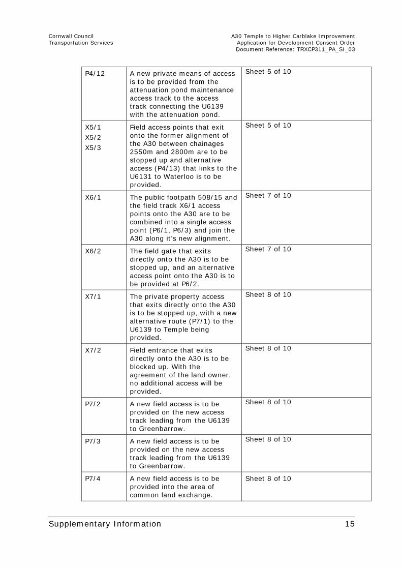
P4/12 A new private means of access is to be provided from the attenuation pond maintenance access track to the access track connecting the U6139 with the attenuation pond.
Sheet 5 of 10
X5/1
X5/2
X5/3
Field access points that exit onto the former alignment of the A30 between chainages 2550m and 2800m are to be stopped up and alternative access (P4/13) that links to the U6131 to Waterloo is to be provided.
Sheet 5 of 10
X6/1 The public footpath 508/15 and the field track X6/1 access points onto the A30 are to be combined into a single access point (P6/1, P6/3) and join the A30 along it’s new alignment.
Sheet 7 of 10
X6/2 The field gate that exits directly onto the A30 is to be stopped up, and an alternative access point onto the A30 is to be provided at P6/2.
Sheet 7 of 10
X7/1 The private property access that exits directly onto the A30 is to be stopped up, with a new alternative route (P7/1) to the U6139 to Temple being provided.
Sheet 8 of 10
X7/2 Field entrance that exits directly onto the A30 is to be blocked up. With the agreement of the land owner, no additional access will be provided.
Sheet 8 of 10
P7/2 A new field access is to be provided on the new access track leading from the U6139 to Greenbarrow.
Sheet 8 of 10
P7/3 A new field access is to be provided on the new access track leading from the U6139 to Greenbarrow.
Sheet 8 of 10
P7/4 A new field access is to be provided into the area of common land exchange.
Sheet 8 of 10
Cornwall Council A30 Temple to Higher Carblake Improvement Transportation Services Application for Development Consent Order Document Reference: TRXCP311_PA_SI_03
Supplementary Information 16
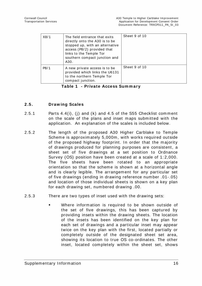
X8/1 The field entrance that exits directly onto the A30 is to be stopped up, with an alternative access (P8/2) provided that links to the Temple Tor southern compact junction and A30.
Sheet 9 of 10
P8/1 A new private access is to be provided which links the U6131 to the northern Temple Tor compact junction.
Sheet 9 of 10
Table 1 - Private Access Summary
2.5. Drawing Scales
2.5.1 Parts 4.4(i), (j) and (k) and 4.5 of the S55 Checklist comment on the scale of the plans and inset maps submitted with the application. An explanation of the scales is included below.
2.5.2 The length of the proposed A30 Higher Carblake to Temple Scheme is approximately 5,000m, with works required outside of the proposed highway footprint. In order that the majority of drawings produced for planning purposes are consistent, a sheet set of five drawings at a set position to Ordnance Survey (OS) position have been created at a scale of 1:2,000. The five sheets have been rotated to an appropriate orientation so that the scheme is shown at a horizontal angle and is clearly legible. The arrangement for any particular set of five drawings (ending in drawing reference number .01-.05) and location of those individual sheets is shown on a key plan for each drawing set, numbered drawing .00.
2.5.3 There are two types of inset used with the drawing sets:
Where information is required to be shown outside of the set of five drawings, this has been captured by providing insets within the drawing sheets. The location of the insets has been identified on the key plan for each set of drawings and a particular inset may appear twice on the key plan with the first, located partially or completely outside of the designated sheet set area, showing its location to true OS co-ordinates. The other inset, located completely within the sheet set, shows
Cornwall Council A30 Temple to Higher Carblake Improvement Transportation Services Application for Development Consent Order Document Reference: TRXCP311_PA_SI_03
Supplementary Information 17
where that specific information is displayed on that particular drawing.
In certain circumstances insets have been required and are contained solely within certain drawings to display congested information more clearly.
2.5.4 Where insets are at the same horizontal scale as the drawing, in which they are located, no additional scale information has been provided. Where the horizontal scale within the inset varies to that of the main drawing, this has been clearly identified within the inset.
2.6. Limits Of Deviation
2.6.1 Part 4.4(j) of the S55 Checklist states that “it is unclear why some limits of deviation are set within (ie not outside) the obvious limits of the earthworks”.
2.6.2 This appears to be a detailed drafting error in the plan and the Limits of Deviation should have been shown outside the earthworks. All works (including all earthworks) should be shown within the limits of deviation. All works are, in any event shown on the works plans, are within the DCO boundary as shown on the plans, were the subject of consultation and have been assessed in the ES. Amended works plans will be submitted as soon as possible.
2.7. Earthworks Design Principles
2.7.1 Page 1 of the S51 advice letter and Part 4.4(a) of the S.55 Checklist states that further information on the dimensions of the different elements of the proposed Scheme should be provided to ensure clarity as to the extent of matters assessed in the ES. Also in 4.4(j) of the S55 Checklist it is stated that PINS had “been unable to detect any analysis or geotechnical report proving that the proposed cutting and embankment slopes are, of engineering necessity, set at the angles shown on the cross sections.” As this information is needed to support the compelling case for the extent of the compulsorily purchased land the information below supported by the provision in Appendix B of the A30 Temple to Higher Carblake Ground Investigation Report Revision 3 (document ref 63548) and the A30 Temple to Higher Carblake Improvement
Cornwall Council A30 Temple to Higher Carblake Improvement Transportation Services Application for Development Consent Order Document Reference: TRXCP311_PA_SI_03
Supplementary Information 18
Geotechnical Design Report Rev 1 (document reference 63548/GDR) seeks to supply this information.
2.7.2 The Scheme will link the existing dual carriageway sections of the A30 at Higher Carblake and Temple, dualling 4.5km of existing single carriageway road. The main concept for the route alignment of the value engineered (VE) full dual proposal has remained similar throughout its development. Where small changes have been made, these have taken into consideration the landscape and topography of the area along with the potential environmental impacts and economic constraints of the project.
2.7.3 In order to provide 4.5km of standard (Dual 2 All Purpose) dual carriageway between Higher Carblake and Temple Tor, the main route alignment proposes to widen the existing single carriageway by approximately 13m. The new section of road will have a standard cross section consisting of: carriageways of 7.3m (each with two lanes of 3.65m), 1m hard strips either side, verges of 2.5m and a central reserve of 2.5m wide which will incorporate a vehicle restraint system (VRS) along its length. The footprint of the proposed main alignment will require approximately 12ha of permanent land take outside of the highway boundary.
2.7.4 In developing the design, it has been the intention to reduce the footprint of the Scheme where possible whilst ensuring that desirable geometric highway standards have not been compromised. This has been achieved principally by following the current mainline geometry of the A30 and minimising or eliminating ‘at grade’ junctions or side accesses where practicable.
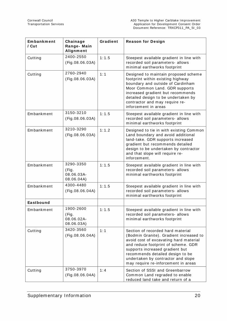
2.7.5 Highway cuttings and embankments are designed to a factor of safety of 1 in accordance with BS EN 1997 parts 1 and 2 (eurocode 7). From knowledge of previous highway schemes in the area on both the trunk road and county road networks, typical soil conditions in the construction of those schemes have allowed gradients of between 1V:1.5H and 1V:3H to achieve that required factor of safety. Where embankment or cutting slopes have been required within the A30 VE design, they have been designed at 1:1.5 to reduce the overall footprint of the Scheme and associated environmental and economic impacts. The exceptions to this is firstly at locations
Cornwall Council A30 Temple to Higher Carblake Improvement Transportation Services Application for Development Consent Order Document Reference: TRXCP311_PA_SI_03
Supplementary Information 19
where areas of land are, by agreement, to be returned to landowners or where landscape and visual impacts are of key importance and in these cases embankments or cuttings have been designed at a shallower gradient (generally 1:3) to enable practical future use of those areas and/or to ensure the slopes fit into the surrounding landscape. Secondly, where the footprint of the scheme is required to fall within a particular land boundary, those sections of embankments or cuttings have been designed at a steeper gradient of between 1:1.5 and 1:1. In these cases, the Geotechnical Design Report in Appendix B, has recommended that re-inforcement of the slope design be carried out by the contractor.
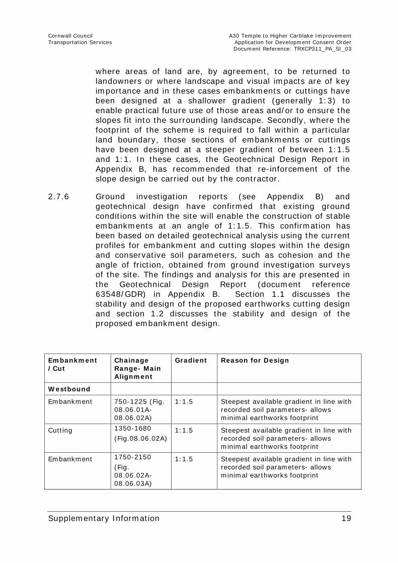
2.7.6 Ground investigation reports (see Appendix B) and geotechnical design have confirmed that existing ground conditions within the site will enable the construction of stable embankments at an angle of 1:1.5. This confirmation has been based on detailed geotechnical analysis using the current profiles for embankment and cutting slopes within the design and conservative soil parameters, such as cohesion and the angle of friction, obtained from ground investigation surveys of the site. The findings and analysis for this are presented in the Geotechnical Design Report (document reference 63548/GDR) in Appendix B. Section 1.1 discusses the stability and design of the proposed earthworks cutting design and section 1.2 discusses the stability and design of the proposed embankment design.
Embankment /Cut
Chainage Range- Main Alignment
Gradient Reason for Design
Westbound
Embankment 750-1225 (Fig. 08.06.01A-08.06.02A)
1:1.5 Steepest available gradient in line with recorded soil parameters- allows minimal earthworks footprint
Cutting 1350-1680
(Fig.08.06.02A) 1:1.5 Steepest available gradient in line with
recorded soil parameters- allows minimal earthworks footprint
Embankment 1750-2150
(Fig. 08.06.02A-08.06.03A)
1:1.5 Steepest available gradient in line with recorded soil parameters- allows minimal earthworks footprint
Cornwall Council A30 Temple to Higher Carblake Improvement Transportation Services Application for Development Consent Order Document Reference: TRXCP311_PA_SI_03
Supplementary Information 20
Embankment /Cut
Chainage Range- Main Alignment
Gradient Reason for Design
Cutting 2400-2550
(Fig.08.06.03A) 1:1.5 Steepest available gradient in line with
recorded soil parameters- allows minimal earthworks footprint
Cutting 2760-2940
(Fig.08.06.03A) 1:1 Designed to maintain proposed scheme
footprint within existing highway boundary and outside of Cardinham Moor Common Land. GDR supports increased gradient but recommends detailed design to be undertaken by contractor and may require re-inforcement in areas
Embankment 3150-3210
(Fig.08.06.03A) 1:1.5 Steepest available gradient in line with
recorded soil parameters- allows minimal earthworks footprint
Embankment 3210-3290
(Fig.08.06.03A) 1:1.2 Designed to tie in with existing Common
Land boundary and avoid additional land-take. GDR supports increased gradient but recommends detailed design to be undertaken by contractor and that slope will require re-inforcement.
Embankment 3290-3350
(Fig. 08.06.03A-08.06.04A)
1:1.5 Steepest available gradient in line with recorded soil parameters- allows minimal earthworks footprint
Embankment 4300-4480
(Fig.08.06.04A) 1:1.5 Steepest available gradient in line with
recorded soil parameters- allows minimal earthworks footprint
Eastbound
Embankment 1900-2600
(Fig. 08.06.02A-08.06.03A)
1:1.5 Steepest available gradient in line with recorded soil parameters- allows minimal earthworks footprint
Cutting 3420-3560
(Fig.08.06.04A) 1:1 Section of recorded hard material
(Bodmin Granite). Gradient increased to avoid cost of excavating hard material and reduce footprint of scheme. GDR supports increased gradient but recommends detailed design to be undertaken by contractor and slope may require re-inforcement in areas
Cutting 3750-3970
(Fig.08.06.04A) 1:4 Section of SSSI and Greenbarrow
Common Land regraded to enable reduced land take and return of a
Cornwall Council A30 Temple to Higher Carblake Improvement Transportation Services Application for Development Consent Order Document Reference: TRXCP311_PA_SI_03
Supplementary Information 21
Embankment /Cut
Chainage Range- Main Alignment
Gradient Reason for Design
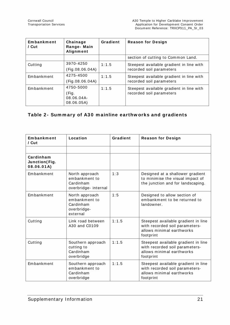
section of cutting to Common Land.
Cutting 3970-4250
(Fig.08.06.04A) 1:1.5 Steepest available gradient in line with
recorded soil parameters
Embankment 4275-4500
(Fig.08.06.04A) 1:1.5 Steepest available gradient in line with
recorded soil parameters
Embankment 4750-5000
(Fig. 08.06.04A-08.06.05A)
1:1.5 Steepest available gradient in line with recorded soil parameters
Table 2- Summary of A30 mainline earthworks and gradients Embankment /Cut
Location Gradient Reason for Design
Cardinham Junction(Fig. 08.06.01A)
Embankment North approach embankment to Cardinham overbridge- internal
1:3 Designed at a shallower gradient to minimise the visual impact of the junction and for landscaping.
Embankment North approach embankment to Cardinham overbridge- external
1:5 Designed to allow section of embankment to be returned to landowner.
Cutting Link road between A30 and C0109
1:1.5 Steepest available gradient in line with recorded soil parameters- allows minimal earthworks footprint
Cutting Southern approach cutting to Cardinham overbridge
1:1.5 Steepest available gradient in line with recorded soil parameters- allows minimal earthworks footprint
Embankment Southern approach embankment to Cardinham overbridge
1:1.5 Steepest available gradient in line with recorded soil parameters- allows minimal earthworks footprint
Cornwall Council A30 Temple to Higher Carblake Improvement Transportation Services Application for Development Consent Order Document Reference: TRXCP311_PA_SI_03
Supplementary Information 22
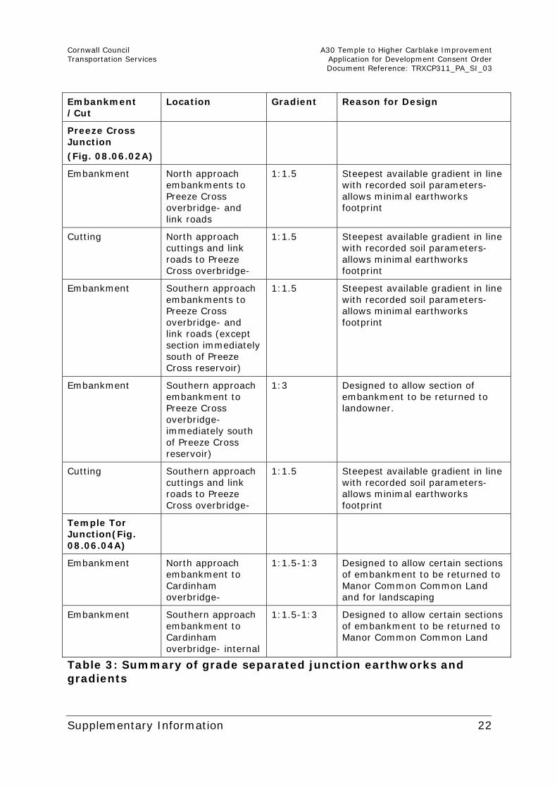
Embankment /Cut
Location Gradient Reason for Design
Preeze Cross Junction
(Fig. 08.06.02A)
Embankment North approach embankments to Preeze Cross overbridge- and link roads
1:1.5 Steepest available gradient in line with recorded soil parameters- allows minimal earthworks footprint
Cutting North approach cuttings and link roads to Preeze Cross overbridge-
1:1.5 Steepest available gradient in line with recorded soil parameters- allows minimal earthworks footprint
Embankment Southern approach embankments to Preeze Cross overbridge- and link roads (except section immediately south of Preeze Cross reservoir)
1:1.5 Steepest available gradient in line with recorded soil parameters- allows minimal earthworks footprint
Embankment Southern approach embankment to Preeze Cross overbridge- immediately south of Preeze Cross reservoir)
1:3 Designed to allow section of embankment to be returned to landowner.
Cutting Southern approach cuttings and link roads to Preeze Cross overbridge-
1:1.5 Steepest available gradient in line with recorded soil parameters- allows minimal earthworks footprint
Temple Tor Junction(Fig. 08.06.04A)
Embankment North approach embankment to Cardinham overbridge-
1:1.5-1:3 Designed to allow certain sections of embankment to be returned to Manor Common Common Land and for landscaping
Embankment Southern approach embankment to Cardinham overbridge- internal
1:1.5-1:3 Designed to allow certain sections of embankment to be returned to Manor Common Common Land
Table 3: Summary of grade separated junction earthworks and gradients
Cornwall Council A30 Temple to Higher Carblake Improvement Transportation Services Application for Development Consent Order Document Reference: TRXCP311_PA_SI_03
Supplementary Information 23
3 ENVIRONMENTAL STATEMENT FIGURES
3.1.1. An amended list of Figures to the ES is submitted with this supplementary information (see Appendix A) with changes shown in bold text. It identifies where figures have been superseded by revised figures and where additional figures have been included. The following section identifies which paragraph of the ES the figures relate to and explains what changes have been made.
3.1.2. Figure 01.02 has been updated (to become Figure 01.02A) in order to provide additional annotation as requested on Page 2 of the S51 advice letter including showing:
Surrounding properties referred to in the ES;
Villages close to the Scheme and arrows showing where roads lead to settlements that are not shown on the Figure;
Construction compounds;
Attenuation features;
Areas of Common Land;
Common Land to be lost and land which will replace it;
Locations of the proposed junctions and access roads; and
Heights of overbridges.
3.1.3. Figure 03.01 which sat within the text of the ES has been replaced by Figure 03.01 to ensure that it is legible to the reader and that the route options can be easily identified.
3.1.4. Figures 08.06.01 to 08.06.08 have been replaced by Figures 08.06.01A to 08.06.08A and 08.06.09 to provide further annotation and additional sections through the site to address the comments on Page 2 of the S51 advice letter and Part 4.4(a) of the S55 Checklist. This includes depths of cuttings, heights of overbridges and widths of roads.
3.1.5. Figures 08.05.07, 10, 14, 15 and 16 are superseded by 08.05.07A, 10A, 14A, 15A and 16A, and 08.08.01 to 08.08.10 are superseded by Figures 08.08.01A 08.08.10A to address
Cornwall Council A30 Temple to Higher Carblake Improvement Transportation Services Application for Development Consent Order Document Reference: TRXCP311_PA_SI_03
Supplementary Information 24
concern raised in the S51 advice letter that the photomontages were for illustrative purposes only. Each viewpoint identified on Figure 08.01A is represented by a set of three Figures. The first in each set shows the viewpoint as it is now and includes an inset map so that the reader does not need to refer back to Figure 08.01A. The second Figure in each set is a photomontage showing a representation of the viewpoint in the winter of the first year after the Scheme is completed (2017). The third Figure in each set is a photomontage showing a representation of the viewpoint in the summer of the 15th year after the Scheme is completed (2032).
3.1.6. Set out below is a brief summary of the method used to take the photographs used in the photomontages and how the photomontages were created.
The camera tripod was mounted and levelled in the horizontal and vertical axes.
The following data was recorded for each image and is shown on each photomontage (Figures 08.08.01A to 08.08.10A):
o Camera;
o Lens focal length and horizontal field of view;
o date;
o time;
o weather;
o lighting conditions;
o direction of view;
o viewpoint;
o height above ground level; and
o OS grid co-ordinates.
The photographs were processed back in the office.
The photomontages were produced using Autodesk 3DS Max design 2014 software.
The Photomontages were printed to a minimum resolution of 300 pixels.
Cornwall Council A30 Temple to Higher Carblake Improvement Transportation Services Application for Development Consent Order Document Reference: TRXCP311_PA_SI_03
Supplementary Information 25
3.1.7. References to Figures 08.08.01 to 08.08.10 are to be read as references to Figures 08.08.01A to 08.08.10A in the ES. For example, where the ES refers to Figure 08.08.01 and 02, the reader should refer to 08.08.01A to 02A.
3.1.8. Figure 13.01 has been replaced by Figure 13.01A to include additional annotation so that the reader can orientate themselves within the Scheme. This is to address a comment on Page 2 of the S51 advice letter which relates to a number of the Figures. The references to PRoW have also been updated to ensure the information given is accurate. The reference to this Figure is unchanged in the ES text.
3.1.9. As stated at para.2.3.3 above, Figure 13.02 has been inserted to show more clearly the proposed changes to the PRoW. This Figure relates to paragraph 2.3.23 of the ES. It should also be substituted for the reference to Drawing TRXCP311_PA_2.04 in paragraph 13.8.16 of the ES as they are in effect the same drawing.
3.1.10. As stated in para.2.4.2 above Figures 13.03.00 to 13.03.10 have been inserted in order to illustrate the changes to private access arrangements.
4. ADDITIONAL INFORMATION
4.1. Appendices
4.1.1. Further additional information has been prepared that PINS did not specifically request, but which we consider would be helpful to the Inspector.
4.1.2. Appendix B to this Supplementary Information document includes a copy of the A30 Temple to higher Carblake Ground Investigation Report (document reference 63548) and a copy of the A30 Temple to Higher Carblake Improvement Geotechnical Design Report (document reference 63548/GDR), which should be referred to as Appendix 10.01 of the ES. An earlier version of the GIR is referred to in the references section (10.10) of the Soils and Geology Chapter.
4.1.3. Appendix C to this Supplementary Information document includes an Options Report, which sets out which alternative route options were considered in detail. It should be referred to as Appendix 03.02 of the ES.
Cornwall Council A30 Temple to Higher Carblake Improvement Transportation Services Application for Development Consent Order Document Reference: TRXCP311_PA_SI_03
Supplementary Information 26
4.2. National Networks National Policy Statement
4.2.1. In December 2013, the Government published a consultation draft of a new National Policy Statement (NPS) setting out its policy on road and rail NSIPs. Although it was not available at the time the A30 Temple to Higher Carblake application for development consent was submitted, it is now a material consideration and therefore CC has considered how the NSP applies to the Scheme.
4.2.2. The Scheme complies with Section 2 of the NPS which aims to provide networks which support economic activity and facilitate growth, whilst at the same time reducing congestion and unreliability by improving the existing road network. The reduction in congestion will also result in reduced emissions as sought in Section 3.5, 5.4 and 5.5 of the NPS.
4.2.3. An EIA (Document Reference TRXCP311_PA_6.01), including the consideration of alternatives, has been undertaken in order to identify potential environmental impacts of the Scheme and set out mitigation required to minimise any adverse impacts. This adheres to the Government’s wider environmental policy set out in Section 3.6 and 3.7, as well as Section 4.11 and 4.24 of the NPS.
4.2.4. A Habitat Regulations Screening Assessment (Document Reference TRXCP311_PA_6.05) was carried out for the Scheme and is therefore in accordance with Section 4.18 of the NPS.
4.2.5. The ES has also considered the impact on the health of the population where is may be affected by noise, water and air pollution, dust and community severance. It therefore complies with Section 4.74 and 4.75 of the NPS.
4.2.6. The effects on ecology and geology have also been considered and therefore the Scheme complies with Section 5.15 and 5.16 of the NPS.
4.2.7. The effects of the Scheme on the use of materials and production of waste have been considered in the ES and therefore the Scheme complies with Section 5.35 of the NPS.
4.2.8. A Flood Risk Assessment (Appendix 15.01, Document Reference TRXCP311_PA_6.03) has been carried out for the Scheme. The impact on water resources has also been

Cornwall Council A30 Temple to Higher Carblake Improvement Transportation Services Application for Development Consent Order Document Reference: TRXCP311_PA_SI_03
Supplementary Information 27
considered. It is therefore in compliance with Section 5.85, 5.197 and 5.198 of the NPS.
4.2.9. An assessment of the effects on the historic environment has been carried out and mitigation has been identified in order to protect cultural heritage assets. The Scheme therefore complies with Section 5.114 and 5.115 of the NPS.
4.2.10. An assessment of the effects of noise and vibration has been carried out and mitigation identified where appropriate in accordance with Section 5.174 of the NPS.
4.2.11. A Transport Assessment (Document Reference TRXCP311_PA_5.14) has been carried out to consider the effects of the Scheme on the highway network. This complies with Section 5.184 of the NPS.
Cornwall Council A30 Temple to Higher Carblake Improvement Transportation Services Application for Development Consent Order Document Reference: TRXCP311_PA_SI_03
Supplementary Information 28
APPENDIX A LIST OF FIGURES (VOLUME 2) 01.01 Site Location Plan (in Volume 1 text) 01.02 Route Design (in Volume 1 text) (superseded) 01.02A Route Design (inserted) 01.03 Environmental Constraints Plan 02.01 Construction Phasing 02.02.01-06 Long Sections (inserted) 03.01 Route Options (in Volume 1 text) (superseded) 03.01 Route Options (inserted) 06.01 Air Quality Study area and diffusion tube study 06.02.00-03 Graph showing results from transects (Figures 07.01-07.10 in Volume 1 text) 07.11 Map showing Historic Landscape Character of the proposed
A30 dualling area 07.12 Designated heritage assets of National importance up to c1km
from the scheme 07.13 Key to sequence of archaeological site location maps 1 to 6
(Figures 7.14-7.19) 07.14 Archaeological site location map 1 07.15 Archaeological site location map 2 07.16 Archaeological site location map 3 07.17 Archaeological site location map 4 07.18 Archaeological site location map 5 07.19 Archaeological site location map 6 07.20 Map of Scheme viewshed 07.21 Position of geophysical survey areas in Figures 07.21-07.24 07.22 Geophysical Survey Plan, Area 1 (Higher Carblake) 07.23 Geophysical Survey Plan, Area 2 (Preeze Cross) 07.24 Geophysical Survey Plan, Area 3 (West of Temple) 07.25 Geophysical Survey Plan, Area 4 (Manor Common Junction) 08.01 Zone of Visual Influence and Public Viewpoint Locations 08.02 Landscape Designations 08.03 Landscape Character 08.04 Photograph Locations
Cornwall Council A30 Temple to Higher Carblake Improvement Transportation Services Application for Development Consent Order Document Reference: TRXCP311_PA_SI_03
Supplementary Information 29
08.05.01-16 Site Photographs (08.05.07, 10, 14, 15 and 16 superseded)
08.05.07A, 10A, 14A, 15A and 16A Site Photographs (inserted) 08.06.00 Landscape Mitigation Key Plan 08.06.01-08 Landscape Mitigation (superseded) 08.06.01A-08A Landscape Mitigation (inserted) 08.06.09 Landscape Mitigation (inserted) 08.07.00-05 Key Plan and Woody Vegetation Lost 08.08.01-10 Photomontages (superseded) 08.08.01A-10A Photomontages (inserted) 08.09.01 Visual Impact Assessment Public Viewpoint Locations 08.09.02 Visual Impact Assessment Properties 09.01 .01 Survey Areas 09.01.02 Designated Sites 09.02.00-05 Key Plan and Phase 1 Survey Data 09.03 Area of Bodmin Moor, North SSSI due to be lost and
area due to be replaced (temporary and Permanent) 09.04 Area of South West Moor CWS due to be lost
(temporary and permanent) 09.05.00-05 Key Plan and Habitats Created 09.06.00-02 Key Plan and Dormouse Habitat Affected 09.07.00-05 Key Plan and Dormouse Habitat created 09.08.00-05 Key Plan and Linear features severed for bats 09.09.00-05 Key Plan and Linear features likely to be used by bats 09.10.00-02 Key Plan and Otter Mitigation Features 10.01 Ground Investigation Hazards 12.01 Noise Assessment Study Area, Monitoring Locations and
Receptors 12.02 Do-minimum Noise Level Change Contours 12.03 Short-Term Impact Noise Level Change Contours 12.04 Long-Term Impact Noise Level Change Contours 13.01 Non-Motorised User Access (superseded) 13.01A Non-Motorised User Access (inserted) 13.02 Alterations to Public Rights of Way (inserted) 13.03.00-10 Key Plan and Private Accesses (inserted) 14.01 Community and Private Assets 14.02 Agricultural Land Classification 15.01 Water Environment Study

Cornwall Council A30 Temple to Higher Carblake Improvement Transportation Services Application for Development Consent Order Document Reference: TRXCP311_PA_SI_03
Supplementary Information 30
15.02 Existing Water Environment Features 15.03 Existing drainage catchments 15.04 Drainage strategy 15.05 Proposed drainage network- key plan 15.06 Proposed drainage network- sheet 1 of 5 15.07 Proposed drainage network- sheet 2 of 5 15.08 Proposed drainage network- sheet 3 of 5 15.09 Proposed drainage network- sheet 4 of 5 15.10 Proposed drainage network- sheet 5 of 5