Embed Size (px)
Citation preview
1
ENERGY FIJI LIMITED
TENDER No. MR 271/2019
Supply of five (5) units
33kV Dead Tank Outdoor Circuit Breakers for
Sigatoka Substation
Tender Closing Time & Date: 16.00hrs Wednesday 25th September, 2019

2
INVITATION TO TENDER
ENERGY FIJI LIMITED
INVITATION TO TENDER
Contract for Supply of Five (5) 33kV Outdoor Dead Tank Circuit Breakers for Sigatoka Substation
__________________________________________________________________________
The Energy Fiji Limited invites you to tender for the Supply of Five (5) 33kV Outdoor Dead Tank Circuit Breakers. All tenders for the contract shall be submitted on the appropriate tender form provided and shall include the completed price schedule, technical schedule. The tender shall be on the basis of a lump sum contract based on firm prices. The price should be DDU to, Lautoka Port, Fiji. The deadline for submission of tenders shall be 1600hr on Wednesday 25th September, 2019.

3
Energy Fiji Limited
CONTRACT FOR THE SUPPLY OF FIVE (5) 33kV OUTDOOR CIRCUIT BREAKERS.
Page
SECTION 1 INSTRUCTIONS TO TENDERERS................................................................. 4
SECTION 2A GENERAL TECHNICAL SPECIFICATIONS ................................................ 9
SECTION 2B DETAILED TECHNICAL SPECIFICATION ............................................... 16
SECTIN 3 SCHEDULES.................................................................................................... 27
SCHEDULE D : DEPARTURES FROM THE SPECIFICATION ............................................. 32

4
FIJI ELECTRICITY AUTHORITY
CONTRACT FOR SUPPLY OF FIVE (5) 33kV OUTDOOR CIRCUIT BREAKERS _________________________________________________________________________
SECTION 1 INSTRUCTIONS TO TENDERERS
1. General
The Energy Fiji Limited (hereinafter called the Authority) is a statutory body vested with the responsibility for the provision of electricity supply throughout Fiji. EFL plans to procure Five (5) new 33kV outdoor dead tank circuit breakers with vacuum type 33kV with magnetic actuator circuit breakers.
2. Type of Tender
The Tenderer shall submit a fixed price tender. This requirement shall apply equally to the conforming tender as well as any alternative tender.
3. Compliance with Instructions
The Tender shall be submitted in accordance with these Instructions and the letter of invitation to tender.
4. Notification of Intention to Tender
The prospective Tenderer shall, not less than 28 days prior to the date set for opening of Tenders, notify Authority whether it is his intention to submit a tender.
5. Addenda to Tender
Where the Authority finds it necessary to make amendments to or clarify the requirements of the tender documents during the period of tendering three copies of each Addendum will be forwarded. In the Appendix to Tender shall state the reference number and description of each of the aforesaid Addenda which has been considered during preparation of the Tender.
6. Compliance with Specification
The tender shall be based on the equipment and work specified and shall be in accordance with the Technical Specification. It should be noted that unless departures from specifications are detailed in Schedule I of the Technical Specification, the tender would be taken as conforming to the Specification in its entirety. The Tenderer shall tender for the whole of the Works included in the Specification.

5
7. Delivery Periods
The Tenderer shall submit his tender on the basis which will permit the Works to be completed under normal circumstances by the completion dates stated in Schedule E of the Technical Specification. The expected arrival of the circuit breakers shall be August 2020.
8. Currency and Currency Equivalent
The tender shall be in the currency of the Tenderer's home country. For Tender comparison purposes the currency or currencies in which the tender is offered will be valued in terms of Fijian dollars at the exchange rate quoted for the sale of the foreign currency for Fijian dollars quoted by the ANZ Bank of Fiji on the day the tenders are opened.
9. Signature of Tenderer
A tender submitted by a Partnership shall be signed by one of the members of the Partnership and shall be accompanied by a certified authorization of all the partners authorizing the individual partner to sign on behalf of the Partnership. A tender submitted by a Corporation to the Contract and shall be accompanied by a certified resolution of the Board of Directors authorizing the individual to sign on behalf of the Corporation.
10. Information forming part of the Tender
The Tenderer shall supply with each set of the tender copies of the technical, price and information schedules of the Tender Documents duly completed with all missing information and shall also supply requisite drawings. A copy of the Tenderer's covering letter (if any) shall be submitted with each tender and each tender shall be accompanied by a full set of supporting matter which the Tenderer wishes to have considered by the Authority as supporting information for his tender.
11. Conforming and Alternative Tenders
No Alternative bids shall be acceptable.
12. Non Conforming Tenders
A tender which does not comply with the Conditions of Tendering or in which the technical price information schedules requiring information to be inserted by the Tenderer have not been completed in all respects may be considered informal will be rejected for these reasons.
13. Validity Period of Tenders
Tenders shall remain valid for acceptance within 90 days from the date of opening of tenders and a Tenderer shall not withdraw or amend his tender prior to the expiration
6
of the Validity Period.
In exceptional circumstances prior to expiry of the original tender validity period, the Authority may request the Tenderer for an extension in the period of validity. The request and the response thereto shall be in writing. A tenderer agreeing to the request will not be permitted to amend his tender price.
14. Extension of Closing Time for Tenders
The right is reserved to amend the date set for the opening of tenders to any late date. If it is decided to extend the time for submission of tenders all prospective Tenderers to whom tender documents have been issued will be promptly notified.
15. Lodgement of Tender
The tender bids SHALL be submitted electronically at the following location https://www.tenderlink.com/efl OR can be sent in pdf format in a CD or disk.
It is mandatory:
1. To register your interest and submit a soft copy response, view 'Current
Tenders at: https://www.tenderlink.com/efl. AND 2. Compulsory Hard Copy submission
The bidder shall prepare one original and 1 copy of the technical and the financial proposal, clearly marking each one as:
"ORIGINAL - Technical and PRICE PROPOSAL", “COPY NO. 1 – Technical and PROCE PROPOSAL"
In the event of discrepancy between original and copy, the original shall prevail.
The original and all copies of the bid shall be typed or written in indelible ink (in the case of copies, Photostats are also acceptable) and shall be signed by a person or persons duly authorized to sign on behalf of the bidder, as the case may be. All pages of the bid where entries or amendments have been made shall be initialled by the person or persons signing the bid.
The bid shall contain no alterations, omissions or additions, except those to comply with instructions issued by the Employer, or as necessary to correct errors made by the bidder, in which case such corrections shall be initialled by the persons signing the bid.
The bidder shall seal the original bids and each copy of the bids in an inner and an outer

7
envelope, duly marking the envelopes as "ORIGINAL" and "COPY".
(a) be addressed to the Employer at the following address:
Energy Fiji Limited The Secretary, Tender Committee 2 Marlow Street, Suva, FIJI. Phone: 679 3224 185 Facsimile: 679 331 1882 Email: [email protected]
(b) bear the following identification:
Bid for: Supply of SUPPLY OF FIVE (5) 33kV OUTDOOR CIRCUIT BREAKERS for SIGATOKA SUBSTATION.
Bid Tender Number: MR 271 /2019
DO NOT OPEN BEFORE Wednesday, 25th September, 2019.
(c) It is mandatory for the Bidders to include the following at the reverse of the envelope:
Company name
Address
16. Deadline for Submission of Bids
Bids must be received by the Employer at the address specified above no later than
1600 hours (Fiji Time) Wednesday, 25th September, 2019.
The Employer may, at its discretion, extend the deadline for submission of bids by issuing an addendum in accordance with Clause 11, in which case all rights and obligations of the Employer and the bidders previously subject to the original deadline will thereafter be subject to the deadlines extended.
17. Acknowledgement of Tenders
All tenders received will be acknowledged by post/email within 7 days after the date set for receipt of tenders.
18. Tender Evaluation
After a preliminary analysis to ascertain whether or not the tender is in accordance with

8
the requirements of the tender documents each tender will be considered with particular reference to its price, completion date, design capability, evidence of past performance on contracts of a similar nature, supply of reliable quality equipments and all other matters affecting the Tenderers ability to complete the Contract in accordance with the Authority's requirements.
19. Adjustment of Errors
The Authority reserves the right to adjust arithmetical or other errors in the Tender. Any adjustments made by the Authority to a Tender will be stated to the Tenderer prior to acceptance of the Tender. In the event of discrepancies appearing between words and figures in the Tender, the words shall prevail.
20. Acceptance of Tenders
The Authority shall not be bound to accept the lowest or any tender not to assign any reason for the rejection of a tender and reserves the right to waive any informality in a tender. No tender shall be deemed to have been accepted unless such acceptance is notified to the Tenderer by notice in writing either by handing such notice to the representative of the successful Tenderer or by sending such notice by e-mail, facsimile or airmail post. Such notice shall include any essential identifying details of the tender. The date of acceptance of Tender shall be the date on which the above mentioned notice is given or posted or e-mailed. If the notice shall have been transmitted by fax confirmation of the fax will be sent by airmail post within 48 hours of such transmission.
21. Language of Tender
All Tenders together with any documents submitted by the Tenderer as part of any Tender shall be written in the English language.

9
SECTION 2A
GENERAL TECHNICAL SPECIFICATIONS
CONTRACT FOR SUPPLY OF FIVE (5) 33kV OUTDOOR CIRCUIT BREAKERS for SIGATOKA SUBSTATION.
_________________________________________________________________________
1. SCOPE OF CONTRACT
The scope of this contract is for supply of
i. Five (5) Outdoor 33kV Dead Tank Circuit Breakers complete ii. Current transformers (CT) iii. Associated structures for 33kV Circuit Breaker
The contract should also cover routine testing and witness factory acceptance testing. The circuit breakers should be under warranty for at least 24 months and whether specified in detail or not, necessary for the securing of an efficient operation of the 33kV Circuit Breakers and the associated control and relay equipment.
2. SYSTEM PARTICULARS
System Particulars for 132kV, 33kV and 11kV system applicable in Fiji Islands: 132kV 33kV 11kV
Normal system voltage 132kV 33kV 11kV System Highest voltage 145kV 36kV 12kV Frequency 50Hz 50Hz 50Hz Earthing of Neutral point Directly Earthed through Directly
earthed earthing earthed transformer and
earthing resistor. Design Symmetrical fault level 4500MVA 1125MVA 250MVA Standard kA rated (31.5kA) (31.5kA) (31.5kA)
3. SERVICE CONDITIONS
The Service Conditions applicable in Fiji Islands:
Daily average ambient temperature 32 C
Max ambient temperature 45 C
Annual average ambient temperature 30 C
Minimum ambient temperature 5 C Relative Humidity 95 % Altitude 20 m Maximum Wind Speed (under cyclonic conditions) 90 m/sec - gusting (under cyclonic conditions) Isokeraunic Level 120 Seismic Level – open ended Richter scale 8 on the open ended Richter scale Average Rainfall per year 2663mm

10
Note: Fiji is situated in a region where cyclones are experienced frequently. All plant and
equipment shall be designed and constructed to withstand these extreme conditions. All plant and equipment shall be rust proof, vermin proof and weather proof and
designed to be suitable for a damp, tropical climate, which may be experienced simultaneously.
4. GENERAL DESIGN CRITERIA
i. Insulation Co-ordination
The design of plant and equipment shall be such that insulation co-ordination is provided not only between different items of plant such as transmission line, surge arrestors, transformers, but also between different components of items within a particular item of equipment.
ii. Interchangeability
Corresponding items or parts shall be interchangeable as far as possible.
iii. Maintainability
All plant and equipment supplied by the contractor under this contract shall be maintainable. The contractor shall provide hard copies of operations and maintenance manuals and a soft copy for each breaker (10 copies). The contractor shall supply safe working procedure for maintenance. The contractor shall also supply all necessary tools and equipment required for this purpose. All special tools shall be supplied by the Contractor in 2 sets.
iv. Ventilation
Building, cubicles and similar enclosed compartments shall be adequately ventilated to restrict condensation. All contactors relay coils etc. shall be suitably protected against corrosion and fully tropicalized and have IP64 ratings.
v. Risk of Fire
All apparatus, connections and cabling shall be designed and arranged to minimise the risk of fire and any damage, which might be caused in the event of fire.
5. GURANTEED QUALITY OF MATERIALS AND WORKMANSHIP
All materials supplied and used by the contractor under this contract shall be new and of the high quality and class most suitable for working under the conditions specified and shall withstand the variations of temperature, atmospheric conditions arising under working conditions without distortion or deterioration or the setting up of undue stresses in any part and also without affecting the strength and suitability of the various parts of the work which they have to perform.
11
All work shall be carried out and completed in a neat and professional manner to the approval of the Employer's Representative.
6. STANDARDS
IEC, IEEE and ASNZ Standards are to be adopted in general. Any other national or international standard may be used if such standards are not less exacting than corresponding IEC Standard. In such an instance a copy of the relevant standard should be forwarded.
6.1 International Standards
IEC 61958, 2000 High-voltage prefabricated switchgear and control gear assemblies -
Voltage presence indicating systems IEC 60051-1, 1997 Direct acting indication analogue electrical measuring instruments
and their accessories Part 1: Definitions and general requirement common to all parts
IEC 60051-7, 1984 Direct acting indicating analogue electrical measuring instruments and their accessories Part 7: Special requirements for multi-function instruments
IEC 608150, Heavy Grey Porcelain or Silicon rubber.
6.2 Australian Standards
AS ISO 1000 - 1998 The international system of units AS 1852.441 – 1985 International electrotechnical vocabulary – Switchgear,
controlgear and fuses AS/NZS 1052:1992 CISPR specification for radio interference measuring apparatus
and measurement methods AS 1566 - 1997 Copper and copper alloys – Rolled flat products AS 1734:1997 Aluminium and aluminium alloys – Flat sheet, coiled sheet and plate AS 4398.1–1996 (R2010) Insulators – Ceramic or glass – Station post for indoor and
outdoor use – Voltages greater than 1000 V a.c. - Characteristics AS 4680:2006 Hot-dip galvanized (zinc) coatings on fabricated ferrous articles AS 2067 – 2008 Substations and high voltage installations exceeding 1kV a.c. AS 2650 – 2005 Common specifications for high-voltage switchgear and controlgear
standards AS 2700S – 1996 Colour Standards for general purposes AS/NZS 60137:2008 Insulated bushings for alternating voltages above 1000 V AS 60529:2004 Degrees of protection provided by enclosures (IP Code) AS 62271–100, 2008 High-voltage switchgear and control gear - High-voltage
alternating-current circuit-breakers

12
AS 62271–200, 2005 High-voltage switchgear and control gear - A.C. metal-enclosed
switchgear and control gear for rated voltages above 1 kV and up to and including 52 kV
AS 62271–201, 2008 High-voltage switchgear and control gear - A.C. insulation-enclosed switchgear and control gear for rated voltages above 1 kV and up to and including 52 kV
AS 62217 - 2007 Polymeric insulators for indoor and outdoor use with a nominal voltage > 1000V – General dimensions, test methods and acceptance criteria
AS 60044.1 – 2007 Instrument transformers – Current transformers (IEC 60044-1 Ed.1.1 (2003) MOD)
AS 1675 – 1986 (obsolescent) Current transformers – Measurement and protection (obsolescent)
AS 62271.301 – 2005 High voltage switchgear and control gear – Dimensional standardization of terminals
7. DETAILED DESIGN OF PLANT AND EQUIPMENT
The detailed design of plant and equipment including plant layout, protection, control, supervisory interface equipment, earthing, civil works designs etc. shall be forwarded by the contractor in accordance with acceptable standards and codes of practice.
Notwithstanding the specifications, technical schedules or plant requirements specified by the tender document, the successful contractor shall be fully responsible for ensuring that the design, manufacture or construction of all items of plant and equipment under this contract to be fully functional, compatible with each other technically and otherwise, complying with IEC and/or other relevant standards, and other safety regulations applicable, and to have the installation complete in all respects including finishing, painting, labeling etc.
The successful contractor shall from the commencement of his contract submit to the Employer's Representative his design concept, detailed designs, technical submissions, design, manufacture and construction drawings,
The Employer's Representative will ensure that any revisions required, or in the absence of any such revisions the approval for such drawings, technical submissions, designs or proposals shall be notified to the contractor within a reasonable time period.
8. PLANT AND EQUIPMENT TO BE SUPPLIED
All items of plant and equipment supplied by the contractor under this contract shall be of proven design, manufacture and construction, and shall have been in commercial operation for at least minimum five (10) years. Tenderer should furnish a list of past orders, indicating the type of equipment, location, country, person contact details etc. in support of this.
13
9. INSPECTION AND TESTING
All tests shall be carried out in accordance with the relevant IEC or other standards. Testing requirements are to be read in conjunction with the document EP 00 00 00 15 SP, Common Requirements for Electric Power Equipment. The authority requires the tenderer to allow for One (1) EFL personnel for witness testing of the circuit breakers at the factory as part of the FAT and includes all routine tests as stipulated in the standards.
a) Factory Tests
Complete tests shall be made at the manufacturer’s plant to determine the performance and operating characteristics of the assembled circuit breakers, and their respective accessories and to determine whether or not the guarantees have been met. Unless otherwise specified, all tests shall be carried out in accordance with relevant standard.
b) Routine/acceptance tests minimum acceptance The following routine tests in accordance with AS62271.100 Clause 7 shall be conducted on all circuit breakers and associated equipment. Provide a list of routine tests that will be conducted on each circuit breaker before dispatch.
1. Mechanical operation tests 2. Power frequency voltage test 3. Dielectric Tests on auxiliary & control circuits 4. Measure of resistance of the main circuit 5. Capacitance and dissipation Factor Test 6. Tan Delta 7. Ductance Test 8. Opening & Closing Speed Test (Timing Test) 9. Dielectric and visual checks. 10. Tightness test 11. Partial discharge measurement test 12. Design and visual checks
c) Type test
The circuit breakers shall be of type tested design. It is anticipated that the following type tests in accordance with AS 62271.100 or IEC equivalent. Results of the type tests shall be submitted. Details of test certificates demonstrating compliance with the specifications including the name of test, test station where test was conducted, test date, test certificate number, detailed test report number and results shall be provided. Type test certificate for each of the specified type tests shall be accepted where it can be demonstrated that the circuit-breaker is of a same design to the
14
type tested circuit-breaker. All type test certificate shall be not more than 5 years old
The contractor shall furnish two (2) sets of type test reports for all the tests along with the tender and the details of the offered 33kV Circuit breaker. Includes
1. Braking and making capacity tests 2. Short time withstand current and peak withstand current tests 3. Low and high Temperature tests 4. Lightning impulse voltage test 5. dielectric tests 6. radio interference voltage tests 7. measurement of the resistance of the main circuit 8. temperature-rise tests 9. tightness tests 10. EMC tests 11. mechanical operation test at ambient temperature 12. short-circuit current making and breaking tests 13. capacitive current switching tests (as applicable) 14. verification of the degree of protection 15. humidity test 16. static terminal load tests 17. critical current tests 18. electrical endurance tests
Note: Results of routine tests shall be compared with those of type test results.
10. TRAINING OF EFL PERSONNEL
The Authority requires EFL personnel to be trained on the operation and maintenance of the particular circuit breaker during the Factory Acceptance Test (FAT). Upon receipt of the circuit breakers in Fiji, the EFL representative should be able to conduct a training session on installation, operation, maintenance of equipment to be supplied under this contract.
11. TOOLS AND EQUIPMENT
The tenderer shall forward a list of tools and equipment required for safe operation and maintenance of the installation and includes the cost of supplying such tools and equipment as part of the tender submission.
12. SPARES
The tenderer shall forward a list of manufacturer’s recommended spare parts required for operation and maintenance of the plant and equipment supplied under this contract for a period of 15 years. The cost of supply of these essential spare parts should form

15
part of the contract but should be shown in a separate price schedule.
13. TECHNICAL LITERATURE - OPERATIONS AND MAINTENANCE MANUALS
Tenderers shall furnish all technical literature, including catalogues, test certificates for new equipment supplied. Successful contractor shall forward three (10) copies of all operations and maintenance manuals, spare parts catalogues, and 3 copies of detailed schematic and wiring diagrams on CD ROM in ACAD 2010 format, plus all other documents required for satisfactory operation and maintenance of plant.
14. PACKING
Equipment shall be carefully packed for transport and shipment in such a manner that it is protected from all dust and climatic conditions during loading, transport, unloading and subsequent storage in the open.
Equipment shall be suitably packed and protected against vibration, movement and shock which may occur during loading and transport. Particular care in packing shall be taken when the apparatus is transported by road.
Instruments and fragile items shall be packed separately. All items, which include delicate equipment, shall be sealed in polythene sheeting and silica gel desiccant or vapour corrosion preventive shall be inserted within the polythene packing. Straw shall not be used as packing material.

16
SECTION 2B
DETAILED TECHNICAL SPECIFICATION FOR MAIN ITEMS OF PLANT
CONTRACT FOR SUPPLY OF FIVE (5) 33kV OUTDOOR CIRCUIT BREAKERS
_________________________________________________________________________
1. SWITCHGEARS
A. System Conditions
The proposed 33kV switchgears shall be suitable for use under the following conditions. a. Normal Service Voltage 33kV b. Rated Voltage 36kV c. Number of Poles 3 d. Frequency 50Hz
B. Rated Insulation Level
a. Lightning impulse withstand voltage 200kV
b. One min power frequency withstand voltage 80kV
2. Operating Mechanism
The circuit breaker shall be operated by from the nominal 110V DC Direct Current station battery bank.
Provision should be made for remote indication if vacuum of "charged" and "charge fail"
conditions. An Emergency manual trip device shall be provided and arranged so as to avoid inadvertent operations.
The circuit breaker shall also be operated remotely through interposing relays and
intelligent SEL protection relays. The mechanism shall be capable of latching under maximum duty. Separate hand charging facility shall also be provided. In the event of a failure to latch in the closed position, it shall not be possible for the Circuit breaker to open except at normal speed.
The circuit breakers shall be fitted with dual trip coil and be "trip free". The current
consumption of the trip coil must not exceed 2A.The circuit breaker operating time for protection tripping shall not exceed 0.1 seconds. The circuit breaker operating time shall be given in the technical schedule.

17
The tripping mechanism shall be of a type which acts directly on the circuit breaker
mechanism and which will give positive operation with a battery voltage of 50% of normal. The Tenderer shall state the maximum continuous current the trip coils can sustain the nominal operating current and the minimum pick-up and drop off voltages for all coils in the trip/close circuits. The resistance values of all coils shall also be stated.
The Tenderer shall submit details, including circuit diagrams, of the anti-pumping
feature on the CB and shall state the operating time of any auxiliary devices. The anti-pumping feature shall function correctly in the presence of trip circuit supervision scheme. The anti-pumping device shall not shunt this current.
Provision shall be made for slow manual operation if mechanical adjustment to the
circuit breaker is necessary. The operating mechanism shall be capable of storing enough energy for the operating
sequence of C.B. at minimum temperature.
3. Circuit Breaker Tank / Dead Tank
The circuit breaker should have a sealed aluminium tank incorporating a 3-phase interrupter and actuator module. A stainless steel 316 grade control cubicle is to be mounted beneath the circuit breaker tank. This shall contain the local operating controls and multicore terminals. Where applicable a control module and/or power supply may be included together with any control and protection relays.
The equipment shall be designed for maintenance free operation. The bushings, tank and control box shall be manufactured from materials suitable for use in the most extreme environments...
4. Interlocks
The following interlocks and devices are to be provided for safe operation:
i. Mechanical interlock preventing closing of circuit breaker either manually or
electrically at any position between connected and disconnected. ii. Mechanical interlock preventing the circuit breaker from being closed if the earthing
switch is closed. iii. Mechanical interlocks preventing closing of earth switch if the corresponding circuit
breaker is in service position. iv. Electrical interlock to allow closing of bus earth switch only if all circuit breakers in
respective bus section are in open and disconnected position. v. Electrical interlock preventing the closing of transformer circuit breakers if circuit is
energised from other end.

18
vi. Interlock to prevent closing of any breaker if bus earth switch is closed. vii. Mechanical interlock preventing the manual closing of the circuit breaker unless the
secondary circuits plug is connected and secured to the socket and blocking the removal of the plug if circuit breaker is closed.
viii. Electrical circuit preventing the remote closing of the circuit breaker if it is disconnected.
The circuit breaker shall be closed and opened for test purposes when in the isolated position.
It must be possible to 'safety' lock the circuit breaker in the disconnected position
independently of whether the circuit breaker is open or closed. The hole, which accepts the shank of the ‘safety’ lock, shall be a minimum of 6mm diameter.
Circuit breakers shall be arranged such that closing in the earthed positions can only be
carried out manually. All mechanical interlocks shall be applied at the point at which manual force will be used, so that stress cannot be applied to parts remote from that point, and shall be capable of withstanding all reasonable forces likely to be encountered by manual operation.
5. Position Selector Devices
Each circuit breaker shall be fitted with a lockable position selector device operated
from the front of the panel such that the circuit breaker may only be operated into the pre-selected position.
6. Auxiliary Switches
Auxiliary switches in addition to those required for the control of the circuit breaker
shall be supplied to control circuit with four each spare contacts. Four of these spare circuits shall close when the circuit breaker closes and the other four shall close when the circuit breaker opens. The drum type of switch with wiping contacts is preferred but the type offered shall be capable of adjustment relative to the operating position of the circuit breaker. Contacts shall be rated 120V 10A D.C.
7. Operation Counter
Each circuit breaker shall be fitted with an operation counter actuated from the
mechanism. The counter shall be visible from outside and at a reasonable height below 1.5m after installation
8. Mechanical Indicators
A semaphore or other approved type of indicator to show whether the main contacts
are in the closed or open position shall be provided on each circuit breaker.

19
The indicators shall be clearly visible and preferably located at eye level. If fitted behind a door they shall be clearly visible without the need to open the door.
Semaphores and indicators shall be clearly marked as follows: CB in Closed Position - 'ON' to be marked in white lettering on a red background CB in Open Position - 'OFF' to be marked in white lettering on a green background Only one semaphore marking shall be visible externally at any time and should be
reflective.
9. Isolating Contact for Auxiliary Circuits The connections in the auxiliary circuits between the fixed and moving portions of the
equipment shall be by means of either self-aligning plugs and sockets or a flexible interconnecting harness.
10. Circuit Breaker Control
Circuit Breaker shall be electrically controlled from the following control points. Local Control - Located adjacent to the item of plant to facilitate maintenance, test
operation and emergency operation. Remote/Supervisory Control - Located at National Control Centre where principal items
of the systems are monitored and remotely controlled by SCADA system. All external interlocks and remote indications defeated in the "test" operation. Refer to Schedule B for the complete the IO listing points.
11. Control Switches and Pushbuttons
Control switches shall be of discrepancy type and arranged to operate clockwise when
closing the circuit breakers and anti-clockwise when opening them. They shall be designed to prevent accidental operation. Operation of switches of the discrepancy type shall be affected by two independent movements. Control switches for circuit breakers shall be of the non-locking type with spring return to the "neutral" position. The contacts of switches shall be strong and have a positive wiping action when operated.
Control switches shall be provided with labels to give clear indication as to the direction of each operation, for example, "Open" "Close" etc..
Switch includes
a. REMOTE/LOCAL b. OPEN/CLOSE
20
12. Switchgear Indication and Alarm Healthy trip lamp and push button with normally open contacts shall be provided
connected across trip supply to enable the tripping circuit to be tested while the tripping supply is maintained and the circuit breaker is closed. A resistance shall be included in the circuit to prevent inadvertent tripping of the breaker should the healthy trip lamp become short circuited. Automatic tripping of a circuit breaker shall energise a remote alarm circuit and illuminate the auto trip lamp on the tripped panel. The auto trip lamp shall remain energised until the protection relay has been manually reset.
Alarm indications, when initiated by a maintained contact, shall continue until
automatically cancelled by the opening of the initiating contact. When initiated by a fleeting contact the indication shall continue until cancelled by hand.
13. Indicating Lamps (LEDs) and Fittings
Indicating lamps fitted into the facial of switch and instrument cubicles or panels shall be adequately ventilated. Indicating lamps should be of 110V DC LIGHT EMITTING DIODE (LED) type.
Lamps shall be easily removed and replaced from the front of the panel by manual
means not requiring the use of extractors. The bezel of metal or other approved materials holding the lamp glass shall be easily removable from the body of the fitting so as to permit access to the lamp and lamp glass.
The lamps shall be clear and must fit into an accepted standard form of lamp holder.
The rated lamp voltages should be 25 percent in excess of the auxiliary supply voltage. The lamp glasses shall be in standard colours, red, green, white and amber. The colour
shall be in the glass and the different coloured glasses shall be interchangeable. Transparent synthetic materials may be used instead of glass, provided such materials have fast colours and are completely suitable for use in tropical climate.
LED Schneider fitting bulb indications includes:
c. OPEN d. CLOSE
14. Miniature Circuit Breakers
Facilities shall be provided for protection and isolation of circuits associated with
protection control and instruments. They shall be of approved type and grouped, as far as possible, according to their functions. They shall be clearly labelled, both on the

21
panels and the associated wiring diagrams. Facilities shall be provided to enable the control circuits for circuit breaker to be individually isolated for maintenance purposes. Miniature air circuit breaker (MCB) shall comply with BS 3871 part 1. A label shall be fixed immediately below each MCB base clearly showing the rating of the MCB.
15. Earthing
The secondary circuit of each current transformer shall be earthed at one point only.
The yellow phase of the three phase Voltage Transformer secondary winding shall be earthed. Means shall be provided for these earth connections to be disconnected at a readily accessible position for testing.
16. Secondary Wiring All secondary control wiring in circuit breakers, panel wiring and the like shall be carried
out in a neat and systematic manner with cable supported clear of the panels and other surfaces at all points to obtain free circulation of air.
In all cases, the sequence of the wiring terminals shall be such that the junction
between multi-core cables and the terminals is effected without crossover. Claw washers or crimped connectors of approved type shall be used to terminate all small wiring. Insulating bushings shall be provided where necessary to prevent the chafing of wiring. All PVC insulated panel wiring shall comply with the requirements of BS 6231 Type A or B as appropriate.
Conductors shall generally have a minimum cross section equivalent to 50/0.25mm
(2.5mm²) but single stranded conductors should only be employed for rigid connections which are not subject to movement or vibration during shipment, operation or maintenance. Flexible conductor’s equivalent to 30/0.25mm (1.5mm²) or small sizes generally shall only be employed with written approval of the purchaser. All cables will be PVC-PVC type with steel wire armour. Control cables exposed to sunlight and weather should be in flexible conduits. Others should be neatly mounted on cable trays
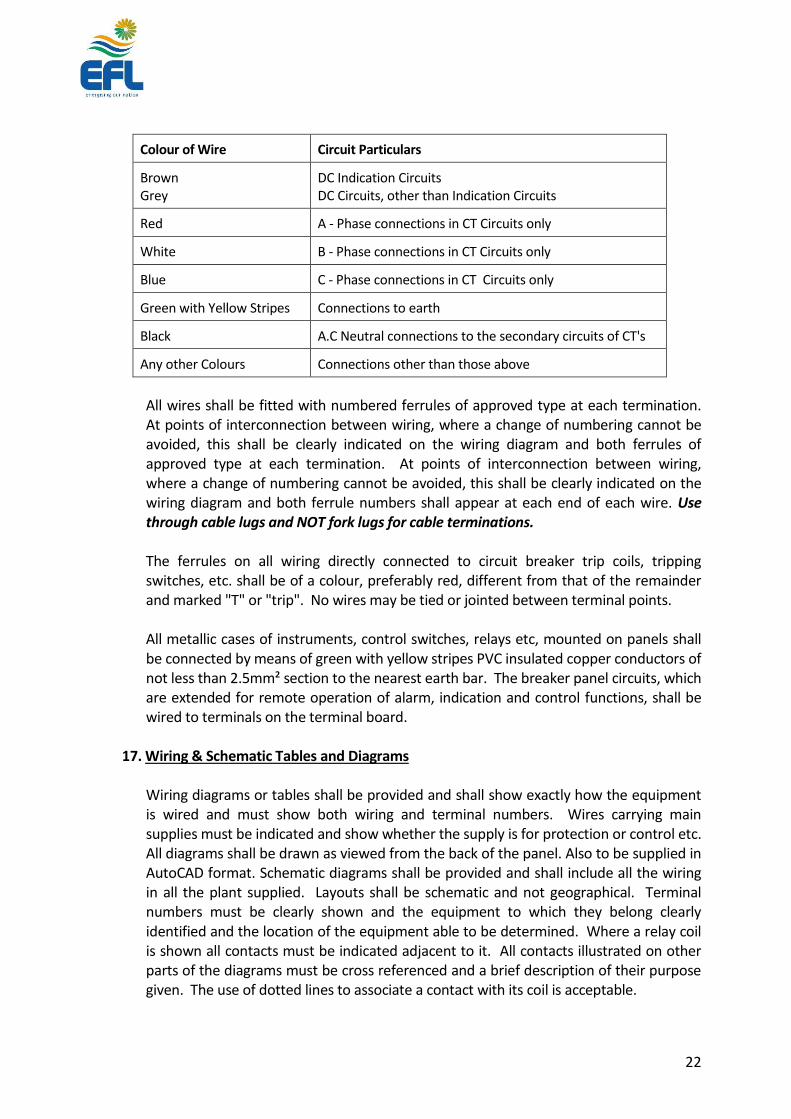
Each CB and its associated equipment shall have one marshalling box for all the necessary wiring connections to separate panels. At the marshalling point, junction boxes shall be fitted with removable covers so that the terminals and connections can be made readily accessible. All control circuit wiring and auxiliary switch contacts shall be brought out to these junction boxes. The ends and taps of each CT secondary winding shall be brought out to the terminal strip where selection of CT ratios will be made as required. These terminals should be of the type, which has the provision for CT shorting. Wire colours shall be as follows:
22
Colour of Wire Circuit Particulars
Brown Grey
DC Indication Circuits DC Circuits, other than Indication Circuits
Red A - Phase connections in CT Circuits only
White B - Phase connections in CT Circuits only
Blue C - Phase connections in CT Circuits only
Green with Yellow Stripes Connections to earth
Black A.C Neutral connections to the secondary circuits of CT's
Any other Colours Connections other than those above
All wires shall be fitted with numbered ferrules of approved type at each termination. At points of interconnection between wiring, where a change of numbering cannot be avoided, this shall be clearly indicated on the wiring diagram and both ferrules of approved type at each termination. At points of interconnection between wiring, where a change of numbering cannot be avoided, this shall be clearly indicated on the wiring diagram and both ferrule numbers shall appear at each end of each wire. Use through cable lugs and NOT fork lugs for cable terminations.
The ferrules on all wiring directly connected to circuit breaker trip coils, tripping switches, etc. shall be of a colour, preferably red, different from that of the remainder and marked "T" or "trip". No wires may be tied or jointed between terminal points.
All metallic cases of instruments, control switches, relays etc, mounted on panels shall be connected by means of green with yellow stripes PVC insulated copper conductors of not less than 2.5mm² section to the nearest earth bar. The breaker panel circuits, which are extended for remote operation of alarm, indication and control functions, shall be wired to terminals on the terminal board.
17. Wiring & Schematic Tables and Diagrams
Wiring diagrams or tables shall be provided and shall show exactly how the equipment
is wired and must show both wiring and terminal numbers. Wires carrying main supplies must be indicated and show whether the supply is for protection or control etc. All diagrams shall be drawn as viewed from the back of the panel. Also to be supplied in AutoCAD format. Schematic diagrams shall be provided and shall include all the wiring in all the plant supplied. Layouts shall be schematic and not geographical. Terminal numbers must be clearly shown and the equipment to which they belong clearly identified and the location of the equipment able to be determined. Where a relay coil is shown all contacts must be indicated adjacent to it. All contacts illustrated on other parts of the diagrams must be cross referenced and a brief description of their purpose given. The use of dotted lines to associate a contact with its coil is acceptable.

23
18. Bushing and Insulators
Self-contained bushings within the scope of IEC 137 shall be separately rated and tested
in accordance with that standard. The Tenderer shall also show by partial discharge measurements or by other means that the bushing, when mounted in a complete circuit breaker, has a satisfactory electrical stress distribution pattern. The Tenderer shall supply drawings showing the construction and mounting of all terminals and bushings or equivalent insulation in sufficient detail to indicate the mechanical strength characteristics of the solid insulation characteristics of the solid insulation material used. Bushing construction shall be such as to allow free expansion of the central conductor. Necessary details of the bushing shall be provided that is; type, material, make, country of origin, applicable standards, type tested, colour, external creepage distance, maximum partial discharge level and provide list of type tests conducted with dates and names of test station.
19. Anti-Corrosion Precautions
In choosing materials and their finishes, due regard is to be given to the humid tropical conditions under which equipment is to work. Equipment offered shall be constructed of materials and be finished in such a way that corrosion is minimised.
a. Current carrying parts shall be made from non ferrous metal. b. Materials and combinations of materials used in the construction of the equipment
shall be selected and arranged to prevent electrolytic corrosion. c. Aluminium and its alloys, whether used for current carrying or structural purposes,
shall be resistant to auto electrolytic and chemical action. d. Ferrous parts shall be either hot-dip galvanised or painted. e. Plastic materials are not recommended f. IP64 rated weatherproof control panel.
Surfaces to be galvanised or painted shall be sound, clean and free from harmful scale,
rust, grease, moisture or any other foreign matter which will in any way detract from the life and usefulness of the coating to BS standards.
20. Environmental considerations suitable to tropical climate and IEC standards
The following environmental factors shall be considered relevant to IEC/AS/BS standards:
Maximum ambient temperature
Maximum height above sea level
Maximum wind pressure
Seismic intensity
Maximum noise level during breaker operation at 1 metre distance (dB)
Maximum radio interference voltage at 1 MHz

24
Corona extinction voltage (kV) 21. Labels and Engraving
Labels shall be white background with black letters ferrules. They shall be made of
engravable phenolic material machine engraved with suitably sized vertical characters as shown in Figure 14 of BS 308. Small labels shall be fixed with a suitable adhesive, larger labels such as those used on test switches shall be fixed with No. 8BA or similar brass screws tapped into the panel. All labels and escutcheon titles shall be approved by the purchaser. The labels to include
1. Feeder Name (600mm X 100mm) 2. Feeder ID e.g. 4A20 3. Open and close (100mm X 40mm)
22. Auxiliary Supply The electricity supplies for auxiliaries will be:
i) 240V AC at 50Hz Single Phase for panel heaters.
ii) 110V DC station battery bank for Auxiliary supplies for essential indication, controls, protection, alarms and circuit breaker closing and tripping.
The circuit breaker shall be capable of operating reliably at voltages down to 50% for circuit breaker tripping and 80% for other circuits.
23. Handling Facilities To facilitate erection and maintenance, all equipment that cannot be conveniently
handled by slings shall be fitted with, or have provision for fitting, eyebolts for lifting purposes.
24. Name Plate & Diagram
The Circuit Breaker shall be provided with a name plate marked with rating data in
accordance with IEC 56 clause 5.9. The name plate shall also record the highest short circuit and current rating to which the equipment has been tested.
25. Anti-Condensation Heaters Any major items of the breaker panel which are liable to suffer from internal
condensation due to atmospheric or load variations shall be fitted with heating devices controlled by thermostats suitable for electrical operation at 240 Volts A.C @ 50Hz single phase of sufficient capacity to raise the internal ambient temperature by 5oC. The electrical apparatus so protected shall be designed so that the maximum permitted rise

25
in temperature is not exceeded if the heaters are energised while the apparatus is in operation.
Where fitted, a suitable terminal box and AC control switch circuit breaker shall be
provided and mounted in an accessible position.
26. Control Panels, Instruments and Wiring Routine tests shall be carried out in accordance with the appropriate IEC
recommendations. Secondary wiring tests at 2kV for one minute. 27. Minimum Power Consumption The circuit breaker shall have a facility, such as capacitor bank, to allow minimum power consumption from the station DC supply. This shall operate in such a way that it takes minimum current from the battery bank but supplying required power to the actual operation of the breaker from make and break. 28. Size of the Circuit Breaker The circuit breaker dimension shall be of very suitable size. The width in particular has to be no more than 1400mm. This is to allow safe working distance from the 33kV breaker to 33kV isolator. As of general setup, on the either sides the circuit breaker, there will be 1 each 33kV isolator. The installation distance of a circuit breaker and an isolator is 2800mm. However, the distance between the live part of the Isolator and the breaker, upon installation, decrease significantly. Therefore, the breaker width shall be no more than 1400mm to compromise this standard.
2. PROTECTION Protection scheme shall be compatible with the existing Protection system in EFL and
wired up to the control panel and labelled. Generally, the Current Transformers, CTs in the circuit breaker should be able to handle
the following protection schemes:
1. Line/ Transformer Differential Protection 2. Distance protection 3. Overcurrent/ earth fault 4. Earth Fault Protection 5. Bus Zone Protection
The protection relays shall comply with the requirements of BS 142. The CT inputs of withdrawable type or plug in type relays shall be automatically short-

26
circuited when the relay is withdrawn or unplugged, respectively. The successful contractor shall provide the adequate numbers of CT, interposing CT
with adequate numbers of secondaries of sufficient ratings to ensure proper functioning of the Protection Scheme specified. Schedule A list the CT requirement of the four circuit breakers.

27
SECTION 3 SCHEDULES Page SCHEDULE A SCHEDULE OF TECHNICAL PARTICULARS 28 SCHEDULE B CT RATIOS & CLASS 30 SCHEDULE C DRAWINGS 31 SCHEDULE D DEPARTURES FROM THE SPECIFICATION 32 SCHEDULE E EVALUATION CRITERIA 33

28
SCHEDULE A: Schedule of TECHNICAL PARTICULARS for Main items
EFL Value Manufacture
Manufacturer/Supplier
Degree of Protection IP64
Type of Circuit Breaker Outdoor
Interrupting Medium Vacuum
Standards IEC298,694,932
Testing Authority -Certificate/Report Reference
Number of Poles 3
Rated Voltage and Frequency 36kV, 50Hz
Rated Normal Current 2,000A
Impulse Withstand Voltage 200kV
Interrupting current 31.5kA
Power Frequency Withstand Dry 80kV
Power Frequency Withstand Wet 80kV
Rated peak making current 80kA
Breaking Capacity: - Symmetrical RMS kA
- Asymmetrical RMS kA
Short Time withstand - 1 sec RMS, 3sec RMS
Rated operating sequence O-0.3"-CO-3'-CO
Opening Time - Without current
- At 100% of breaking current ms
Maximum Arc duration duty cycle of IEC56-2
Critical Current which max Arc duration occur
Closing Time ms
Method of closing
Method of tripping
Closing Release Coil Current A
Control Voltage 110V DC
Trip coil Current A
Trip coil Voltage 110V DC
Power at Normal Voltage for closing W
Overall dimensions of the CB Unit L×H×W
Weight of CB Complete with all fittings < 800kg
State Compression or Tension N
Minimum Clearance in Air - Between Phases
- Phase to Earth
- Across CB Poles
Insulation Material- Bushings Support Insulators, Operating Rods, Contact Rods
Period equipment has been in commercial operation 15 yrs Minimum

29
Number of trip coils and close coils a) b)
Variation on auxiliary supply voltage
Power consumed by close coil Power consumed by trip coil
Magnetic Actuator rating
Total length of break Type main contact Type of arching contact Type of arc control mechanism
30
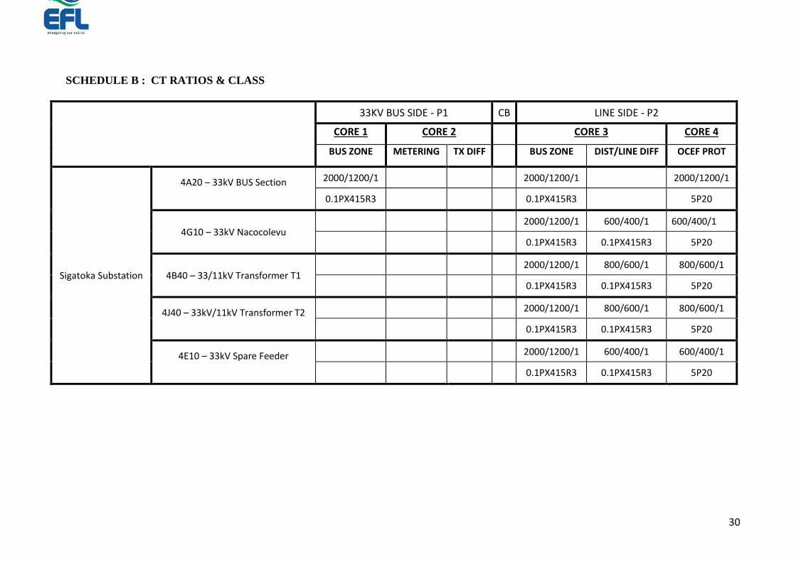
SCHEDULE B : CT RATIOS & CLASS
33KV BUS SIDE - P1 CB LINE SIDE - P2
CORE 1 CORE 2 CORE 3 CORE 4
BUS ZONE METERING TX DIFF BUS ZONE DIST/LINE DIFF OCEF PROT
Sigatoka Substation
4A20 – 33kV BUS Section
2000/1200/1
2000/1200/1 2000/1200/1
0.1PX415R3
0.1PX415R3 5P20
4G10 – 33kV Nacocolevu
2000/1200/1 600/400/1 600/400/1
0.1PX415R3 0.1PX415R3 5P20
4B40 – 33/11kV Transformer T1
2000/1200/1 800/600/1 800/600/1
0.1PX415R3 0.1PX415R3 5P20
4J40 – 33kV/11kV Transformer T2
2000/1200/1 800/600/1 800/600/1
0.1PX415R3 0.1PX415R3 5P20
4E10 – 33kV Spare Feeder
2000/1200/1 600/400/1 600/400/1
0.1PX415R3 0.1PX415R3 5P20

31
SCHEDULE C : Drawings
The following drawings are required to be furnished with tender.
Title Drawing Number.
1 General arrangement for 33kV outdoor circuit and switch panels.
2 A schematic the proposed circuit breaker
3 Schematic protection system
4 Principles of actuators
5 Earthing Drawings
6 Civil drawings
7 Any other relevant to the Circuit Breaker

32
SCHEDULE D: DEPARTURES FROM THE SPECIFICATION
The Tender shall be deemed to be entirely in accordance with the requirements of this Specification, unless otherwise stated. Should any departures from the requirement of this Specification arise, and/or any alternative proposals be submitted, the details shall be outlined below:
Clause No Details of Departure

33
SCHEDULE E PRICE SCHEDULE ON MAIN ITEMS
ITEM
NO.
DESCRIPTION
Quantity DDU To Lautoka Port
Foreign Currency
SUBSTATION Unit Rate Amount
1 CIRCUIT BREAKER
1.1
Sigatoka Substation
4A20 – Bus Section 1
1.2 4G10 – Nacocolevu 1
1.3 4B40 – Transformer T1 1
1.4 4J40 – Transformer T2 1
1.5 4E10 – Spare Feeder 1
2 MISCELLANEOUS
2.1 Manufactures Recommended Spares 2 sets
2.2 FAT Witness Testing 1 set
2.3 Bushing Terminals 5 sets
2.4 Others
TOTAL

34
SCHEDULE F EVALUATION CRITERIA
The following criteria with corresponding scoring and weightings which will be utilised for evaluating the bids forms the Technical Evaluation Section. Those bids which score
above 92% for the Technical Evaluation will be considered for further evaluation to their financial proposals.
Criteria for Evaluation Weighting Score Range
10 - 7 7 – 4 4 - 0
1 Manufacturer’s years of experience in
production of 33kV Switchgear
5.00 Company has more than 20 years
experience
Company has 15 – 20 years
experience
Company has 10 – 15 years experience
3 Number of years the offered model has been
in production and in the market
7.50 Model has been in the market for
more than 15 years
Model has been in the market for 15
– 12 years
Model has been in the market for 3 – 10 years
4 Number of units of offered model sold in
Pacific – Fiji/NZ/Australia
2.50 More than 750 Less than 500 Less than 250
5 Number of years of experience of key
personnel to be involved in project
5.00 More than 10 years for most of the
key personnel
Less than 10 years for most of the
key personnel
Less than 5 years for most of the key
personnel
6 Manufacturer’s Warranty on Switchgear 5.00 More than 2 years 1 – 2 years Less than 1 year
7 Type test reports on Switchgear 5.00 Results meet and exceed the
requirements as per IEC standards
Results do not meet minimum
specifications
Type test reports not submitted or not as per
IEC standards
8 Conformance to acceptable values for routine
tests as specified in tender
2.50 Submits evidence that switchgear
will conform to and exceed
Evidence of switchgear will conform
to most of the test requirements
No evidence of conformance to test
requirements
9 Comprehensiveness of proposed design 2.50 All the design details are
addressed as that would be
expected in an ideal proposal.
Relevant design details are
addressed in terms of design as
that compared to an ideal proposal.
The proposal conforms to most of
the items stated in the specifications
Extent of consideration placed into design is
significantly less than that expected in a
reasonable proposal. Most of the items stated
in specifications are not met.

35
10 Nominal Circuit Breaker parameters 20.00 Circuit breaker parameters exceed
the nominal required performance
ratings
Circuit breaker parameters are
equal to the nominal required
performance ratings
Circuit breaker parameters are below the
nominal required performance ratings
11 Evaluation of Current Transformers 5.00 Offered CT ratings exceed the
specifications and from Europe
Offered CT ratings are equivalent to
the specifications
CTs Offered are below the specification
14 Maintenance Requirements for Switchgear 10.00 Needs maintenance every 3 years
or more or after 10000 operations
Needs Maintenance every 2 - 3
years
Needs Maintenance every 1 - 2 year
15 Safety Requirements for Switchgear 5.00 Meets and exceeds the safety
requirements of the switchgear,
with added consideration to safe
design and operation
Meets most of the safety
requirements for the switchgear
Does not meet the level of safety features for
the switchgear
16 Innovation in Design 15 High degree of innovation
incorporated into design compared
to similar products in market
Evidence of some innovation
incorporated into design
No evidence showing any innovation in design
18 Delivery period and timeline 5.00 Delivery period is within 18 weeks Delivery period is within 24 weeks Delivery period would exceed 28 weeks
19 Quality Control 5.00 Manufacturer has quality system in
accordance with international
standards and produced evidence
of regular third party audits
Manufacturer appears to have a
quality system in place.
Manufacturer has a record of providing
reasonable quality material but provides no
evidence of a quality system
Total 100%

36
TENDER SUBMISSION CHECK LIST
The Bidders must ensure that the details and documentation mention below must submitted as part of their tender Bid Tender Number ______________ Tender Name _______________________________________________
1. Full Company Name: _____________________________________
(Attach copy of Registration Certificate)
2. Director/Owner(s): _______________________________________
3. Postal Address: _________________________________________
4. Phone Contact: _________________________________________
5. Fax Number: _________________________________________
6. Email address: __________________________________________
7. Office Location: _________________________________________
8. TIN Number: _________________________________________ (Attach copy of the VAT/TIN Registration Certificate - Local Bidders Only)
9. Company Registration Number: _____________________________
(Attach copy of the Business License)
10. FNPF Employer Registration Number: _______________________
(For Local Bidders only)
11. Contact Person: ___________________________________
I declare that all the above information is correct. Name: ____________________________

37
Position: ____________________________
Sign: _________________________ Date: ______________________
Tender Submission - Instruction to bidders
It is mandatory for Bidders to upload a copy of their bid in the TENDER LINK Electronic Tender Box no later than 4.00pm (1600hrs Fiji Time) Wednesday 25th September, 2019. To register your interest and tender a response, view 'Current Tenders' at: https://www.tenderlink.com/efl For further information contact The Secretary Tender Committee, by e-mail [email protected] In additional, hard copies of the tender, one original and one copy must be deposited in the tender box located at the EFL Head Office, 2 Marlow Street, Suva, Fiji no later than new time and date to be inserted - Addressed as Tender – MR 271/2019 – Supply of Five (5) Units of 33kV Dead Tank Outdoor Circuit Breakers for EFL’s Sigatoka Substation
The Secretary Tender Committee Energy Fiji Limited Head Office Suva Fiji
Hard copies of the Tender bid will be accepted after the closing date and time provided a soft copy is uploaded in the e-
Tender Box and it is dispatched before the closing date and time.
Tenders received after closing time 4.00pm (1600hrs Fiji Time) Wednesday 25th September, 2019.

38
Will not be considered.
Lowest bid will not necessarily be accepted as successful bid.
It is the responsibility of the bidder to pay courier chargers and all other cost associated with the delivery of the hard copy of the Tender submission.