Embed Size (px)
Citation preview
' • . ^ - , • • " ' - , - . . " •
NASA Technical Memorandum 81909
Support Interference of WindTunnel Models • A SelectiveAnnotated Bibliography •
(NASA-Ta-81909) SUPPORT INTERFERENCE Of N81-20084WIND TUNNEL MODELS; A SELECTIVE ANNOTATEDBIBLIOGRAPHY (NASA) 36 p HC A03/af A01
CSCL TUB UnclasG3/09 41797
?«•."*»..'. -V.
Marie H. Tuttlc and Blair B. Gloss
MARCH 1981
j
"•
-••'
fWNSA
https://ntrs.nasa.gov/search.jsp?R=19810011556 2018-07-15T07:30:39+00:00Z
NASA Technical Memorandum 81909
Support Interference of WindTunnel Models - A SelectiveAnnotated Bibliography
Marie H. Tuttle and Blair B. GlossLangley Research CenterHampton, Virginia
NASANational Aeronauticsand Space Administration
Scientific and TechnicalInformation Branch
1981
INTRODUCTION
The intent of this bibliography is to list publications that might be useful to personsinterested in support interference of wind tunnel models. The publications included have notbeen limited to any particular type of model support or Mach number range. Some papers "ofhistorical interest are included.
Since sting interference effects may be discussed in publications with no mention made ofthis fact in the title or abstract, omissions will occur as a result of oversight. It is hopedthat omissions of important papers will be called to the attention of the compilers, so thatpossible subsequent updated versions or supplements of this bibliography may be more nearlycomplete and, therefore, more useful.
The arrangement is chronological by date of publication. An author index is included forthe convenience of the user.
In many cases, abstracts used are from the NASA announcement bulletins "Scientific andTechnical Aerospace Reports" (STAR) and "International Aerospace Abstracts" (IAA). Inother cases, authors' abstracts were used. License was taken to modify or shorten abstracts,using only parts pertinent to the subject of the bibliography. If a paper has appeared inseveral forms, mention is made of this fact. Accession numbers, report numbers, and otheridentifying information are included in the citations in order to facilitate the filling ofrequests for specific items.
Xxx-xxxxx number documents have limited distribution, which is indicated in thecitations, and are not abstracted in this bibliography.
When requesting material from your library or other source, it is advisable to include thecomplete citation, omitting the abstract.
Availability sources of the different types of materials are given below:
Acquisition Number Type of Material Source
Axx-xxxxx Published literature American Institute of Aeronauticsavailable from AIAA and Astronautics
Example: or in journals or Technical Information ServiceA70-29885 conferences, etc., 750 Third Avenue
as indicated. New York, NY 10017
Acquisition Number
Nxx-xxxxx
Example:N68-17455
Xxx-xxxxx
AD-numberand Otherwise
Examples:X73-75159AD-905771IM-52790
Type of Material
Report literature
Includes reportliterature withlimited distribution,documents with nocall numbers, andothers having theNACA library callnumbers.
Source
National TechnicalInformation Service (NTIS)
5285 Port Royal RoadSpringfield, VA 22161
NASA Scientific andTechnical Information Facility
P.O. Box 8757B.W.I. Airport, MD 21240
A "#" after an acquisition number (Axx-xxxxx or Nxx-xxxxx) indicates that thedocument is also available in microfiche form.
BIBLIOGRAPHY
1 * Bacon, David L.: Model Supports and Their Effector)the Results of Wind Tunnel Tests. NACA-TN-130, Feb. 1923,14pp.
The airflow about a model while being tested is oftensufficiently affected by the model support to lead toerroneous conclusions unless appropriate corrections areused. In this paper some new material on the subject ispresented, together with a review of the airfoil supportcorrections used in several other laboratories.
*NACA, Langley Field, Virginia
2 Ferri, Antonio: Supersonic Tests of Projectiles inGermany and Italy. NACA Report ACR No. L5H08. Oct.1945. NACA-Wartime Report-L-152.
Test data taken in the small supersonic tunnel at theGottingen Laboratory and in the high-speed tunnel atGuidonia were analyzed by NACA at Langley Field. Thefollowing comments were made by A. Ferri in this reportabout the sting supports used in the tests:
Gottingen:
"The models each had a diameter of 0.393 inchand were supported by a sting attached to the rearface. The dimensions of the sting and the tare systemadopted are not known."
Guidonia:
"The forces on each model were determined byuse of a three-component balance. The model wasattached to the balances by a sting on the projectileaxis on the rear face of the projectile. The sting,although of small diameter, affected the experimentalresults somewhat since it increased the pressure on therear face of the projectile. It was necessary, therefore,to make an accurate tare measurement by suspendingthe model on a faired strut attached to the side of theprojectile."
3 'Perkins, Edward W.: Experimental Investigation of theEffects of Support Interference on the Drag of Bodies ofRevolution at a Mach Number of 1.5. NACA-TN-2292, Feb.1951, 50 pp. (Formerly NACA-RM-A8B05. Feb. 1948).
N62-54292
Tests were conducted to evaluate the effects of supportinterference on the drag characteristics of two bodies ofrevolution at zero angle of attack and at a Mach number of1.5. The models, which varied only in their afterbody shape,were tested in the smooth condition and with roughnessadded to determine the support-interference effects for bothlaminar and turbulent flow in the boundary layer. Drag andbase-pressure measurements were made for most tests over arange of Reynolds numbers, based on model length, of from0.6 million to 5.0 millions to determine the effect of varyingthe length or diameter of the rear support. A side support incombination with a rear support was used to evaluate themagnitude of the interference. The schlieren method wasused to determine the effect of the support on the flow overthe afterbody of the models. For the body of revolution withzero boattailing and either laminar or turbulent flow in the
boundary layer, the fore drag was not affected by the rearsupport; however, the base drag and, therefore, the total dragdepended on the support configuration used. The base dragwas found to depend on the diameter of the rear, supportover the complete range of rear-support diameters used in theinvestigation, but was independent of changes in supportlength as long as the support length was at least 5.2 bodydiameters. For the body of revolution with appreciableboattailing and laminar flow in the boundary layer, both thebase drag and the fore drag were independent of changes inthe length or diameter of the rear support as long as thelength was equal to or greater than 1.7 body diameters andthe diameter was equal to or less than 0.4 body diameter.
*NACA, Ames Aeronautical Laboratory, Moffett Field, Calif.
4 "Osborne, Robert S.: High-Speed Wind-TunnelInvestigation of the Longitudinal Stability and ControlCharacteristics of a 1/16-Scale Model of the D-558-2Research Airplane at High Subsonic Mach Numbers and at aMach Number of 1.2. NACA-RM-L9C04. April 1949,87 pp.
A 1/16-scale model of the D-558-2 was tested (using fourstings having various diameters) to determine its force,longitudinal stability, and control characteristics at Machnumbers from 0.6 to 0.95 and at a Mach number of 1.2.Much data is given. The effects of chordwise fences on theforce and moment characteristics of the model are alsopresented.
•NACA, Langley Aeronautical Laboratory. Langley Field,Virginia
5 'Chapman, Dean R.: An Analysis of Base Pressure atSupersonic Velocities and Comparison with Experiment.NACA Rep. 1051, 1951, 23 pp. (Formerly NACA-TN-2137,July 1950).
An analysis is made of base pressure in an inviscid fluid,both for two-dimensional and axially symmetric flow. Anapproximate semi-empirical analysis for base pressure in aviscous fluid is developed. Experimental results also arepresented concerning the support interference effect of acylindrical sting.
*NACA, Ames Aeronautical Lab.. Moffett Field, Calif.
6 "Bogdonoff, S. M.: A Preliminary Study of ReynoldsNumber Effects on Base Pressure at M = 2.95. Journal of theAeronautical Sciences, vol. 19, no. 3, pp. 201 - 206, March1952.
Chapman made a fairly complete study of the effect ofsupport sting diameter and length at M = 2.9 in NACA Rept.1051. For laminar flow, ratios of support diameter to bodydiameter below 0.6 and ratio of support length to bodydiameter over 2.8 gave no effect on base pressure. Forturbulent flows, the ratio of support length to body diameterof over 2.8 also gave no effect. However, for ratios of supportdiameter to body diameter from 0.6 down to 0.3 (thesmallest tested), the base pressure is still rising slightly. Forthe configuration used in these tests (a ratio of supportdiameter to body diameter of 0.25 and a length to bodydiameter ratio of 3.9), it seems reasonable to. assume that the
results obtained are, at most only slightly affected by thesupport system.
'Princeton Univ., Princeton, N.J.
7 *Reller, John O., Jr.; and *Hamaker, Frank M.: AnExperimental Investigation of the Base PressureCharacteristics of Nonlifting Bodies of Revolution at MachNumbers from 2.73 to 4.98. NACA-TN-3393. March 1955,45pp. (Formerly NACA-RM-A52E20, May 1952).
Base pressure characteristics of related nonlifting bodiesof revolution were investigated at free-stream Mach numbersfrom 2.73 to 4.98 and Reynolds numbers from 0.6 x 10^ to8.8 x 10°. The basic body shape was a 10-caliber tangentogive with a cylindrical afterbody. The variation of basepressure coefficient with free-stream Mach number andReynolds number was determined for laminar-, transitional-,and turbulent-boundary-layer flow. Some effects of bodyfineness ratio, nose-profile shape, and afterbody shape(boattail) were also included in the investigation. Modelnumber 2 ( \ Id = 5) was used with supports of various lengthsand diameters to evaluate the effect of support interferenceon measured base pressure.
(Appendix A, pp. 17 — 18, discusses support interference.)
•NACA, Ames Aeronautical Laboratory, Moffett Field, Calif.
8 'Osborne, Robert S.; and *Mugler, John P., Jr.:Aerodynamic Characteristics of a 45° SweptbackWing-Fuselage Combination and the Fuselage Alone Obtainedin the Langley 8-Foot Transonic Tunnel. NACA-RM-L52E14.Sept. 1952,71 pp.
A fuselage and a wing-fuselage combination employing awing with 45° sweepback of the 0.25-chord line, aspect ratio4, taper ratio 0.6, and NACA 65A006 airfoil sections havebeen investigated in the slotted test section of the Langley8-foot transonic tunnel at Mach numbers from 0.6 to 1.13for angles of attack up to 36°. Maximum lift was reached atMach numbers from 0.6 to 0.92.
(See page 7 for discussion of sting interference. No data isgiven but some sting interference effects were used to correctdrag results.)
*NACA, Langley Aeronautical Laboratory, Langley Field,Virginia
9 'Hart, Roger G.: Effects of Stabilizing Fins and aRear-Support Sting on the Base Pressures of a Body ofRevolution in Free Flight at Mach Numbers from 0.7 to 1.3.NACA-RM-L52E06. Sept. 1952. 19 pp.
Isolated fuselages were flight-tested at Mach numbersfrom 0.7 to 1.3 in order to determine the contributions ofthe body and the fin-body interference to the total drag ofpreviously tested combinations. A rear-support sting similarto those used in wind tunnels was tested with one of thefuselages.
•NACA, Langley Aeronautical Laboratory, Langley Field,Virginia
10 'Coletti. Donald E.: Investigation of the AerodynamicCharacteristics of the NACA RM-10 Missile (with Fins) at a
Mach Number of 1.62 in the Langley 9-Inch SupersonicTunnel. NACA-RM-L52J23a, Dec. 1952,21 pp.
An investigation was made of a 0.050-scale model of theRM-10 missile at a Mach number of 1.62 and a Reynoldsnumber of 2.66 x 10 .̂ Measurements were made of lift,drag, and pitching moment over an angle-of-attack range of±5°. The effects of the ratio of sting-shield diameter to basediameter were also investigated. Comparisons are made withresults of tests in other facilities at widely different Reynoldsnumbers.
•Langley Aeronautical Laboratory, Langley Field, Virginia
11 *Love, Eugene S.; and 'O'Donnell, Robert M.:Investigations at Supersonic Speeds of the Base Pressure ofBodies of Revolution With and Without SweptbackStabilizing Fins. NACA-RM-L52J21a. Dec. 1952,66 pp.
Results are presented from an investigation at Machnumbers of 1.62, 1.93, and 2.41 of the variation withReynolds number of the base pressure on bodies ofrevolution at zero lift, with and without sweptbackstabilizing fins. Included are the effects of varying nose andbase shapes and cut-off length, the effects of the presence ofsting supports of varying diameter, and the effects ofdisturbances entering the wake. The over-all Reynoldsnumber range was approximately from 1 x 10° to 10 x 10 .
*NACA, Langley Aeronautical Laboratory, Langley Field,Virginia
12 "Baughman, L. Eugene; and *Jack, John R.:Experimental Investigation of the Effects of SupportInterference on the Pressure Distribution of a Body ofRevolution at a Mach Number of 3.12 and ReynoldsNumbers from 2 x 10⁶ to 14 x 106. NACA-RM-E53E28,Aug. 1953, 18 pp.
N62 -62091
An experimental investigation was performed todetermine the effect on base and forebody pressures of usinga sting modified with varying length splitter plates and finsinstead of a conventional sting to support a cone-cylinderbody of revolution. The investigation was conducted at aMach number of 3.12 for a Reynolds number range of 2 x10⁶ to 14 x 106 and for an angle of attack range of 0° to 9°.For Reynolds numbers of 8 x 10^ and 14 x 10^ there was anegligible effect of the splitter plate modification on the basepressure, and at a Reynolds number of 2 x 10⁶ there was asmall effect. Positioning the leading edge of the splitter plateat or ahead of the base made no appreciable change in theinfluence of the modifications on base pressure at a Reynoldsnumber of 14 x 10°\ With the fin-type modification therewas a small increase in base pressure.
•NACA, Langley Aeronautical Laboratory, Langley Field,Virginia
13 'Kavanau, L. L.: Results of Some Base PressureExperiments at Intermediate Reynolds Numbers with M =2.84. Univ. of Calif. Rept. HE-150-117, Oct. 22, 1953. 14pp. Also "Journal of the Aeronautical Sciences," vol. 21, no.4, April 1954, pp. 257 - 260, 274.
Base pressure data are presented for a cone-cylindermodel at Mach Number 2.84 and Reynolds Numbers from45,000 to 400,000. These data verify the maximum in basepressure coefficient (pb/p) predicted by Crocco and Leeswhich occurs between the completely laminar and turbulentflow regimes. Sting length requirements for this model aresummarized reflecting the growth of the critical wake regionwith decreasing Reynolds number. Results from varying thebase pressure orifice location and sting diameter are alsogiven.
*Univ. of California, Berkeley, California
Research supported by Office of Naval Research (USN) andthe Office of Scientific Research (USAF).
14 "Love, Eugene S.: A'Summary of Information onSupport Interference at Transonic and Supersonic Speeds.NACA-RM-L53K12. Jan. 1954, 26 pp.
This document is a compilation of available informationon the problem of support interference at transonic andsupersonic speeds.
*NACA, Langley Aeronautical Laboratory, Langley Field,Virginia
15 'Harkins, W. O.: Base Pressure and Static Pressure fora Cone-Cylinder at a Nominal Mach Number of 5.8. CIT,Guggenheim Aeronautical Lab. Memorandum No. 19, July20, 1954,28pp.
AD-42331 N-32953
An experimental investigation was made in the GALCITHypersonic Wind Tunnel to determine the base pressure andstatic pressure on a cone-cylinder at a nominal Mach numberof 5.8 in both one-phase and two-phase flow. The scope ofthe investigation was a determination of interference datanecessary for proper evaluation of base pressure results,investigation of the effect of Reynolds number on basepressure, and a comparison of experimental and theoreticalstatic pressure distribution on a cone-cylinder. As has beennoted by other investigators, viscous effects in hypersonicflow were quite pronounced and demonstrated the increasednon-linearity of the problems in hypersonic flow. Before anybase pressure determination could be made, it was necessaryto obtain interference data at the test Mach number of 5.8.Chapman has specifically stated the need for suchinterference data at the higher Mach numbers. Briefly, thedata was obtained by various combinations of sting and sidesupport of the models. The critical length of the sting wasdetermined. Sting diameter was varied to study the effect ofthis modification.
•Guggenheim Aeronautical Laboratory. California Instituteof Technology. Pasadena, California.
Contract No. DA-04-495-Ord-19
16 Kavanau, L. L.: Fluid Flow and Heat Transfer at LowPressures and Temperature-Base Pressure Studies in RarefiedSupersonic Flows. Univ. of Calif. Berkeley Institute ofEngineering Research Rept. HE-150-125 (Series 20), Nov. 1.1954. 119 pp. (Condensed from a Ph.D. Thesis.)
N-33862
Base pressures were measured on a simple cone-cylinderconfiguration over a range of Mach number M and Reynoldsnumber Rejjbased on model length): 159 < Rej_ <800 for M=* 2 and 920 < ReL < 7400 for M=«4. Preliminary testsshowed a considerable variation of pressure existing over thebase area, thus requiring an area-mean determination of thebase pressure for every flow condition. Investigations weremade of support interference effects arising from the relativesize of both the sting diameter and the sting length ascompared to the model diameter. Some effects due to heattransfer were also studied. Supplementary pressuredistributions were taken on the model surface upstream ofthe base and in the wake at one Mach and Reynolds numberwhich was characteristic of this flow regime. The basepressure coefficient in free molecule flow is calculated forcomparison purposes. A' discussion is presented of theseresults together with experimental and theoretical works ofother investigators.
(See no. 24 in this compilation for a journal article by thisauthor on the same topic.)
Contract N7-onr-295-Task 3
17 'Tunnell, Phillips J.: An Investigation of Sting-SupportInterference on Base Pressure and Forebody Chord Force atMach Numbers from 0.60 to 1.30. NACA-RM-A54K16a, Jan.1955,19pp.
Various configurations of rear sting supports were testedon one wing-body model with a turbulent boundary layerover the aft portion of the fuselage to determine theinterference effects on the base pressure and foredragcharacteristics. The tests were made at a Reynolds number of5.4 x 10^ based on fuselage length and over a Mach numberrange of 0.60 to 1.30.
*NACA, Ames Aeronautical Laboratory, Moffett Field. Calif.
18 'Donaldson, I. S.: The Effect of Sting Supports on theBase Pressure of a Blunt-Based Body in a Supersonic Stream.The Aeronautical Quarterly, vol. 6. Aug. 1955, pp. 221 -229.
Experiments have been made to find the effect of theratio of sting to base diameter on the base pressure of anaxially symmetric body at zero incidence in a supersonicstream. The Mach number of the flow was 1.994 and themodel boundary layer was turbulent. The model used was aone inch diameter circular cylinder without boat-tailing. Itpassed through and was supported upstream of the nozzlethroat. This method of support allowed measurements to bemade in the important (and hitherto unexplored) case of zerosting diameter. As the sting to base diameter ratio wasincreased from 0 to 0.85, the base pressure decreased. Theminimum value reached was approximately 0.8 of the valueit would have at the base of a two-dimensional body with asimilar ratio of boundary layer thickness to base height. Thebase pressure coefficient rose rapidly to zero as the ratio wasfurther increased to unity. Under the conditions of theexperiments, with a sting to base diameter ratio of 0.4 thebase pressure coefficient differed from that without a stingby approximately ten per cent. With the more modest ratioof 0.2, the difference was approximately three per cent.
•Fluid Motion Lab., Univ. of Manchester, England
19 'Estabrooks, Bruce B.: Tests on Sting-SupportInterference Conducted in the Transonic Model Tunnel —Phase I. AEDC-TN-54-28. Jan. 1955. 62 pp.
N-35203
Tests in the Transonic Model Tunnel with both porousand solid wall test sections indicated that an outward bulge inthe tunnel wall in the vicinity of the sting support strutprevented premature choking in the support strut area, andprovided a favorable centerline Mach number distribution,and auxiliary mass-flow characteristics.
*ARO, Inc., Arnold Engineering Development Center,Tullahoma, Tenn.
Contract AF18(600)-1233.
20 'Estabrooks, Bruce B.: Tests on Sting-SupportInterference Conducted in the Transonic Model Tunnel —Phase II. AEDC-TN-55-13. Oct. 1955,51 pp.
N-39653
This report presents the results of the investigation of thesting-support system for the PWT Transonic Model Tunnelwith several different types of test-section walls, wallmodif ications, blockage models, and with a modelrepresenting the upstream portion of the scavenging scoop.Results, obtained for the Mach number range from 0.80 to1.20, are presented in the form of Mach number distributionsalong the tunnel centerline, tunnel pressure-ratiorequirements, and auxiliary mass-flow requirements.
*ARO. Inc., Arnold Engineering Development Center,Tullahoma, Tenn.
Contract AF40(6001-620
21 'Estabrooks, Bruce B.: Tests on Sting-SupportInterference Conducted in the Transonic Model Tunnel —Phase III. AEDC-TN-55-29, Oct. 1955. 39 pp.
N-39654
The results of the third phase of the experimentaldevelopment program conducted in the Transonic ModelTunnel on a 1/16-scale model of the sting-support system forthe transonic circuit of the Propulsion Wind Tunnel arepresented. A means of decreasing the interference effects ofexposed longitudinal stringers on the tunnel characteristics inthe Mach number range from 0.80 through 1.20 wasdetermined. The results include Mach number distributions,tunnel pressure-ratio requirements, and auxiliary mass-flowrequirements.
*ARO. Inc., Arnold Engineering Development Center,Tullahoma, Tenn.
Contract AF40(600)-620
22 *Sivier, Kenneth R.; and 'Bogdonoff. Seymour M.:The Effect of Support Interference on the Base Pressure of aBody of Revolution at High Reynolds Numbers. PrincetonUniv. AED No. 332; AFOSR-TN-55-301, Oct. 1955, 40pp..21 refs.
N-39957,
An experimental investigation has been made of theeffect of a rear support sting on the base pressure of an
ogive-cylinder body at a Mach number of 2.97 and atReynolds numbers from 10 x 106 to 40 x 10 .̂ The bodywas mounted on wings to permit the measurement of a freebase pressure. Stings having diameters from 0.6 to 0.0625times the body's base diameter were employed to check thesting effect. Checks were made to assure that the presentresults were not affected by finite sting length. A secondogive-clyinder body, without mounting-wings, was supportedon a rear sting to check the effect of the wing on the basepressure. For the range of Reynolds numbers considered inthis investigation, no critical sting diameter was found toexist. In fact, the variation of base pressure with stingdiameter was greatest for the smallest diameters. The error inbase pressure introduced by a sting of any given diameter wasfound to be a function of Reynolds number. Although thecurves of base pressure versus sting size showed a tendency tolevel off at the lower sting diameters, the assumption byseveral investigators that this indicated a critical sting size wasfound to be in error.
'Princeton Univ., Dept. of Aeronautical Engineering
Contracts - N6onr-270and AF18(600)-498
23 'Schueler. C. J.; and 'Strike, W. T.: AnInvestigation of the Lift, Drag, and Pitching MomentCharacteristics of AGARD Calibration Models A and B.Rep. No. AEDC-TN-55-34, Feb. 1956, 49 pp.
AD-81581
An investigation of the lift, drag, and pitching momentcharacteristics of AGARD Calibration Models A and B hasbeen made in Tunnel E-1 of the Gas Dynamics Facility,Arnold Engineering Development Center. The tests onCalibration Model A covered a Mach number range of 2.0 to4.0 and.a Reynolds number range of 1.5 x 10⁶ to 27 x 106.Calibration Model B was tested over a Mach number range of1.7 to 4.0 and a Reynolds number range of 3 x 10^ to 22 x10°. Included in the investigation, but limited in scope, weretests to determine the effects of model sting size on basepressure measurements.
'Arnold Engineering Development Center, ARO, Inc.,Tullahoma, Tenn.
Contract AF40(600)-620
24 'Kavanau, L. L.: Base Pressure Studies in RarefiedSupersonic Flows. Journal of the Aeronautical Sciences, vol.23, no. 3, March 1956, pp. 193 - 207, 230. (Also presentedat the 23rd Annual Meeting of IAS. New York, Jan. 1955.)
X 65-83405
(Number 16 in this compilation has the same abstract andauthor.)
'Lockheed Aircraft Corps, Missile Systems Division.Sunnyvale, CA
Supported by Office of Naval Research (USN) and Office ofAir Research (USAF)
25 Patterson, R. T.: The Axial-Tube Testing Technique inSupersonic Wind Tunnels. David W. Taylor Model Basin AeroRept. 895, April 1956,23 pp.
N-45426
This report describes the axial-tube testing techniquein supersonic wind tunnels, the advantages of thistechnique, the effect of an axial tube on test-sectionflow, and the axial-tube boundary-layer characteristics.The axial tube, located on the longitudinal axis of thechannel, begins in the stilling chamber, extendsdownstream through the contractor and nozzle, and endswith its base in the testing region. A drag balance isinstalled in the tube near the base and models aremounted on the balance concentric with the tube.
26 'Klann, John L.; and *Huff, Ronald G.:Experimental Investigation of Interference Effects ofLateral-Support Struts on Afterbody Pressures at Mach1.9. NACA-RM-E56C16. May 1956. 13 pp.
A series of single and double, unswept, lateral-supportstruts were tested at Mach 1.9 and RN = 3.2 x TO6
per foot on a cone-cylinder body at zero angle ofattack. All strut-body interference effects were small
. beyond a length of eight body diameters. However, anonreflected shock wave due to the presence of thesupport struts at the tunnel walls did affect afterbodypressures. Reduction of the leading-edge strut anglealleviated this disturbance.
*NACA, Lewis Flight Propulsion Laboratory, Cleveland,Ohio
27 *Cahn, Maurice S.: An Experimental Investigationof Sting-Support Effects on Drag and a Comparisonwith Jet Effects at Transonic Speeds. NACA Rept.1353. 1958. 32 pp. (Formerly NACA RM-L56F18a, July1956.)
Various dummy stings were tested on the rear of arelated series of afterbody shapes for Mach numbers from0.80 to 1.10 and Reynolds numbers based on bodylength from 15.0 x 10⁶ to 17.4 x. 106. A method ispresented whereby approximate ' sting interferencecorrections can be made to models having afterbodyshapes and sting supports similar to those of these testsif the Reynolds numbers are of the same order ofmagnitude and a turbulent boundary layer exists at themodel base. Also presented is an analysis of jetduplication by use of a sting.
*NACA, Langley Aeronautical Laboratory, Langley Field,Virginia
28 'Covert, Eugene E.: Supersonic Wind TunnelInvestigations to Determine the Interference Effects ofthe Sting Used to Support the Model in the Tunnel.WADC-TR-55-214. Sept. 1956. 110 pp.
(U.S. Gov't Agencies Only)
AD-130778 N-52790
* Naval Supersonic Lab., Massachusetts Institute ofTechnology, Cambridge, Mass.
Contract AF-3316161-2828
29 'Tournier, Marcel; and 'Laurenceau. P.:Suspension Magnetique d'une Maquette en Soufflerie.
(Magnetic Suspension of a Model in a Wind Tunnel.) LaRecherche Aeronautique, no. 59, July - Aug. 1957, pp.21 - 27.
(For English translation see N80-71571#.)
A new method of suspending models has beenworked out and has been subjected to varyingconditions of speed of flow in tests demonstrating thefuture use for which it was conceived. This paperprovides a rapid review of- methods utilized up to nowto "support" the body in wind-tunnel tests which showsthat no real material supports possess all the qualitieswhich are required of them. These considerations ledthe O.N.E.R.A. (National Office of Aeronautical Studiesand Research) to seek a means of supporting a modelin a position determined by immaterial bonds in orderthat the fluid flow around the body be disturbed byneither the sides of the test cell (the consequences ofwhose perturbation creates the object of particularstudies) nor by the supports. Several solutions have beenimagined: the first consists of suspending a permanentmagnet intended to support the model and to balancethe resultant aerodynamical forces. The other utilize oneor more iron electromagnets acting astride a bar of softiron which constitutes the body of the model.
•ONERA. 92320, Chatillon. France
30 *Lee, George; and 'Summers. James L.: Effects ofSting-Support Interference on the Drag of an Ogive-CylinderBody With and Without a Boattail at 0.6 to 1.4 MachNumber. NACA-RM-A57I09, Dec. 1957, 28 pp.
Various sting-support configurations were tested on twobodies of revolution to determine the interference effects onthe foredrag and base drag. The tests were made at aReynolds number of 8 x 10" based on model length and overa Mach number range of 0.6 to 1.4.
•NACA, Ames Aeronautical Laboratory, Moffett Field, Calif.
31 •Whitf ield, Jack 0.: Critical Discussion ofExperiments on Support Interference at SupersonicSpeeds. AEDC-TN-58-30, August 1958. 49 pp.
AO-201108 •
An experimental investigation of the effect of the stingsupport length on the drag of slender ogive-cylinder models,with and without afterbody boat-tailing, has been conducted.These tests were made at Mach numbers 3.00 and 3.98 over aunit Reynolds number range from 10^ to 10° per inch. Thecritical sting length as well as the base pressure is shown to bestrongly dependent on the transition location and the lengthReynolds number. The often quoted rule-of-thumb geometryratio of three base diameters for an allowable sting length wasinadequate for this investigation. The range of critical stinglengths encountered during this study was fromapproximately 5.5 for ReL = 1 x 10⁶ and M = 4.0 toapproximately 1.0 for ReL = 7 x 10⁶ and M = 3.0.
•Arnold Engineering Development Center. ARO, Inc.,Tullahoma, Tennessee
Contract No. AF 40(6001-700 S/A 13(59-1)
32 'Rogers. E. W. E.: A Background to the Problems ofWind-Tunnel Interference. National Physical Laboratory Rep.NPL/Aero/370. Jan. 1959, 26 pp.. 59 refs. Prepared forAGARD Meeting on Interference Effects in AerodynamicTest Facilities, Brussels, March 2 — 5, 1959.
N-70223
The progress that has been made in the field ofwind-tunnel interference is briefly surveyed and some of thepresent-day difficulties are pointed out. In the concludingsection an attempt is made to assess the direction in whichfuture work is required.
'National Physical Laboratory, Aerodynamics Division,Great Britain
33 'Whitfield, J. D.: Support Interference at SupersonicSpeeds. AGARD Rep. 300, March 1959. 26 pp. Presented at.Interference Effects Meeting of AGARD Fluid DynamicsPanel, Rhode St. Genese, March 2-5, 1959.
N-108.671
The effect of sting-length interference on the base andafterbody drag of models with cylindrical and boat-tailedafterbodies are discussed. Results of tests with bluff-shapemodels supported by fine wires are presented and comparedwith results obtained with conventional sting-type supports.Effects of Mach number, length, Reynolds number, and unitReynolds number on support interference are discussed.Results of experimental studies at the United States AirForce's Arnold Engineering Development Center, GasDynamics Facility (AEDC-GDF) are presented. The effects ofsting-length interference are shown to be strongly dependenton the transition location as well as the length Reynoldsnumber for the case with transitional wake flow.
'Arnold Engineering Development Center. Tullahoma,Tennessee
34 'Zonars, D.: Large Angle of Attack Model-StingInterference Effects at Transonic Speeds. (Presented atAGARD Fluid Dynamics Panel, Rhode St. Genese, Belgium,Mar. 2-5, 1959.) AGARD Rep. 301, March 1959, 39 pp.
N80-73598
An experimental investigation has been conducted in theWADC 10-ft Transonic Wind Tunnel for the purpose ofdetermining sting interference characteristics of a cylindricalbody of revolution with an ogive nose. The sting-supportsystem consisted of three different sting sizes which wereattachable to either the body base, nose, or model side. Thismodel-support system provided a method for obtaining angleof attack data through a range 0° to 180° with resulting stingeffects throughout the angle range. Six-component internalstrain gage balance tests were conducted throughout theMach number range 0.6 to 1.2. The majority of the test wasconducted at a stagnation pressure of 1200 Ib/ft^ abs. withresulting Reynolds number variations from 0.225 x 10^ to0.297 x 106 based on the model body diameter.
•Wright Air Development Center, Flight Dynamics Lab.(FDX), Wright-Patterson AFB, Ohio
35 'Rebuffet. Pierre: Effets de Supports sur I'Ecoulementa I'Arriere d'un Corps. (Effects of Supports on the Flow at
the Rear of a Body). Presented at AGARD Wind TunnelTests and Models Working Group, March 1959, AGARD Rep.302, 39 pp. (French text, English summary).
N80-71569#
With a view to determining the effects of supports onmodels with a flat base, two cases are examined, in asupersonic flow with a turbulent boundary layer. The firstconcerns the effect of various obstacles situated upstream ofthe two-dimensional base, at Mach 2. The second relates to abody of revolution passing through the throat of the jet fromupstream to downstream. The interference of obstaclessimulating supporting masts is examined for the base, bothbare and with a sting, at Mach 1.94. Without any support, thedrag of a conical-cylindrical body of revolution was measuredby means of the ONERA magnetic suspension. Theinterference of various stings was studied at Mach 2.4, with alaminar boundary layer and with a separated turbulentboundary layer. The mechanism of the interference of asting, progressively approached axially to the base, wasdetermined.
'Directeur Scientifique Adjoint de I'Aerodynamique a'TO.N.E.R.A., 92320 Chatillon. France
36 'Reid, J.; and 'Hastings, R. C.: Experiments on theAxisymmetric Flow Over Afterbodies and Bases at M = 2.0.R.A.E. Aero 2628, Oct. 1959, 67 pp.
N-79928
The effects of profile shape and boundary-layer growthon the side and base pressures of an axisymmetric afterbodyare investigated. The tests were made at M =2 with aturbulent boundary-layer on a cylinder, three truncatedcones and three truncated parabolae. Firstly, theboundary-layer profile was measured at the shoulder and baseof each of the conical and parabolic afterbodies, and thegrowth of the layer was traced along the cylinder and theshortest parabola. Secondly, the pressure was measured alongeach of the conical and parabolic afterbodies. Thirdly, theeffect of boundary-layer thickness on the base pressure of thecylinder, and afterbody angle on the base pressure of thecones and parabolae were investigated. Supplementary testswith the cylinder show the axial pressure distribution behindthe base, and also the effect of a sting or an externaldisturbance on the base pressure. The boundary-layer dataare compared with two theoretical methods of calculatingboundary-layer growth; the afterbody pressures are comparedwith the theoretical distributions in inviscid flow, and theeffect of afterbody angle on the base pressure is comparedwith two semiempirical methods of correlation.
'Royal Aircraft Establishment, Farnborough, England
37 'Reese, David E., Jr.; and 'Wehrend, William R., Jr.:Effects of Sting-Support Interference on the Base Pressuresof a Model Having a Blunted Cylinder Body and a ConicalFlare at Mach Numbers of 0.65 to 2.20. NASA-TM-X-161.Feb. 1960.23pp.
N71-75826
Various sting-support configurations were investigatedwith a model incorporating a conically flared afterbody todetermine the interference effects on the pressure at the
model base. The tests were made at Mach numbers from 0.65to 2.20 at angles of attack up to 18° at a Reynolds number(based on the model body diameter) varying from amaximum of 1.1 x 10 to a minimum of 0.5 x 10 .
•NASA, Ames Research Center, Moffett Field, CA
38 'Schueler, C. J.: An Investigation of SupportInterference on AGARD Calibration Model B.AEDC-TN-60-35, Feb. 1960, 28 pp.
N-79995
• Tests were conducted in the 12-inch supersonic windtunnel (Tunnel E-1) of the von Karman Gas DynamicsFacil i ty, Arnold Engineering Development Center(VKF-AEDC) to determine the critical sting length forAGARD Calibration Model B with a sting-to-body diameterratio of 0.3. The tests were made at Mach numbers 2, 3. and4 and covered a Reynolds number range of 3.5 x 10 to 13.5x 10⁶ based on the body length. The results indicate that thesting had no significant influence on the model surfacepressure even when interference on base pressure wasmaximum. Over the Mach number and Reynolds numberrange of the tests, negligible interference was introduced bythe windshield for sting length to model diameter ratiosgreater than 2.5.
*Arnold Engineering Development Center, ARO, Inc.,Arnold Air Force Station, Tennessee
Contract No. AF 40(6001-800
39 * Peck ham, D. H.: Exploratory Tests on StingInterference at a Mach Number of 6.8. ARC-CP-566, Oct.1960, 17 pp. (Previously issued as RAE-TN-AERO-2721.)
N63-84979
Tests with slender models at zero incidence showed thatif the length of a supporting sting has to be kept short, it isdesirable for transition to occur upstream of the base of themodel, if interference effects are to be avoided. This type offlow corresponds to full-scale hypersonic vehicles operatingat moderate altitudes. In addition, it was found that therewas no advantage to be gained in using a small diameter sting.If the case of complete laminar flow over a hypersonicvehicle becomes of interest, which may happen if extremealtitudes are considered, greater interference problems wouldarise, and longer stings would be needed.
*Royal Aircraft Establishment, Farnborough. England
40 'Stanbrook, A.; and 'Secomb, D. A.: The FlowAround a Rod Passing Longitudinally Through anAsymmetric Supersonic Nozzle. RAE-TN-Aero 2729. Nov.1960,7pp.
N-95056
Results are given of some experimental measurementsand observations of the effect on the flow of the presence ofa rod held longitudinally in an asymmetric supersonic nozzle(to represent a possible upstream support system) at Mach
numbers from 1.4 to 2.0. Although the static pressures alongthe flat bottom wall were found to be little affected by theintroduction of the rod, evidence of extensive flowseparation from the rod was obtained at Mach numbers of
1.8 and 2.0. The occurrence of these separations implies theexistence of poor distributions of total and static pressure inthe working section.
•Royal Aircraft Establishment, Farnborough, England
41 *Greenwood. G. H.: Free-Flight Measurements of theZero-Lift Drag and Base Pressure on a Wind TunnelInterference Model (M = 0.8 — 1.5). (Previously issued asRAE-TN-Aero 2725. Nov. 1960.) Now ARC-CP-553. 1961,10pp.
N-94483X
Five free-flight models were flown. Roughness bands onthe wings and body of the model are shown to produce asmall but definite increase in the zero-lift drag at all Machnumbers. The measured drag is in fair agreement withcorresponding measurements made in various transonictunnels with differences that could plausibly be explained asthe effects of tunnel interference. The effect of a simulatedwind tunnel support sting is shown to increase the basepressure. The discrepancy between models with and withouta sting is greatest at subsonic speeds and progressivelydecreases with increasing Mach number until at M = 1.4 thesting has no effect on base pressure.
•Royal Aircraft Establishment. Farnborough, England
42 'Savi tsky, Daniel; and *Prowse, Robert E.:Added-Mass and Drag Coefficients of Basic Finner Missile.Davidson Lab., Stevens Inst. of Tech. Rep. no. R-824, Dec.1960.28pp.
N-91490
To determine the drag and added mass for axial motionsof the Basic Finner Missile during constant, accelerated, anddecelerated velocities, a four-inch model was used;rear-support stings (0.47 and 0.61 times the model diameter)were successively used to support the model. Constant speeddrag coefficients obtained with the small and large stingstruts were about 0.40 and 0.46, respectively, at Reynoldsnumbers larger than 3.5 x 10 .̂ At a Reynolds number ofabout 3 x 10 , there was a significant peak in dragcoefficient. The added-rnass coefficient was 0.15 at Reynoldsnumbers larger than 3.4 x 10 . The sting-support strutappeared to have a significant effect on the drag andadded-mass coefficients. Therefore, in future studies .'testsshould be made with side-support struts.
•Davidson Lab., Stevens Institute of Technology, CastlePoint, Hoboken, N.J.
Contract NOrd-16193
43 *Dubois, George; and 'Rouge. Charles: Sur uneMethode de Mesure de la Pression de Culot-Mesure etVisualisation sur une Maquette Cylindro-Conique SuspendueMagne'tiquement a MQ = 7.6. La Recherche Ae'ronautique,no. 79, pp. 35 - 44, Nov. - Dec. 1960. (In French).
N80-71567#
English translation by **R. N. Zapata. On a Method forMeasuring the Base Pressure: Measurement and Visualizationon a Cone Cylinder Magnetically Suspended at MQ = 7.6.Rep. AFOSR-1020; AST-4443-102-61U, May 1961, 38 pp.
N80-71541#
The present paper is concerned with a method formeasuring the base pressure of an axially symmetrical body.This method avoids material supports through the use of theO.N.E.R.A. magnetic suspension for keeping the model onthe axis of the stream at the test section. Thus, the basepressure is measured, with no interactions, by means of anoptical manometer located inside the model. At the sametime, the flow can be visualized by a schlieren system. Thispaper specifies the conditions required for the applicabilityof the method, analyzes the precision of the measurements,discusses the results obtained with and without sting, andcompares them to those previously obtained at lower Machnumbers.
•ONERA. 92320 Chatillon, France"Univ. of Virginia, Charlottesville, Virginia
44 'Stivers, Louis S., Jr.; and "Levy, Lionel L., Jr.:Effects of Sting-Support Diameter on the Base Pressures ofan Elliptic Cone at Mach Numbers from 0.60 to 1.40.NASA-TN-D-354, Feb. 1961, 30 pp.
N62-70928
Measurements were made to determine the effects ofsting-support diameter on the base pressures of an ellipticcone with ratio of cross-section thickness to width of 1 /3 anda plan-form semiapex angle of 15°. The investigation wasmade for model angles of attack from -2° to +20°, at Machnumbers from 0.60 to 1.40, and for a constant Reynoldsnumber of 1.4 million, based on the length of the model. Theresults indicated that the sting interference decreased thebase axial-force coefficients by substantial amounts up to amaximum of about one-third the value of the coefficient forno sting interference. There was no practical diameter of thesting for which the effects of the sting on the base pressureswould be negligible throughout the Mach number andangle-of-attack ranges of the investigation.
•NASA, Ames Research Center, Moffett Field, Calif.
45 'Gray, J. Don: Base-Pressure Measurements withWi re -Suppor ted Models at Supersonic Speeds.AEDC-TN-61-23, March 1961, 24 pp.
N-94336
Base pressure measurements were made with an ogivecylinder and a blunt, boat-tailed cone at M^ = 4 to appraisethe effects of small wire supports. Some measurements with amuch larger blunted cone were made at MOO= 3.5 and 5. Thetests covered a Reynolds number range from about 0.06 to0.48 x 106 per inch. It was found that the small wiresupports generally reduced the base pressure ratio below thatobtained with a small sting support. The results for theogive-cylinder model indicated that when transition wassituated on the model the addition of wires introducednegligible interference.
•Arnold Engineering Development Center, ARO, Inc.,Arnold Air Force Station, Tennessee
Contract No. AF 40(6001-800 S/A 11(60-110).
46 Turner. K. J.: Measurements of Dynamic Stabilityfrom Three Simplified Free-Flight Models of a Supersonic
Research Aircraft (Bristol ER. 134) over the Mach NumberRange 1.2 - 2.6. Rept. AGARD-378, July 1961, 62 pp.
N62-17200#
Values of the lateral stability derivatives yv, nv. lv and lphave been measured on free-flight models of the Bristol ER.134 for Mach numbers between 1.2 and 2.6. These show thatthe aircraft should be laterally stable up to M = 2.6, at least,although the free-flight results indicate a somewhat smallerstability margin than estimates or wind-tunnel measurements.Some additional data on zw and mw have been derived fromthe longitudinal motion. (Effects of sting support arediscussed.)
47 "Valk. H.; and *van der Zwaan, J. H.: A Review ofMeasurements on AGARD Calibration Model B in theTransonic Speed Range. In A Review of Measurements onAGARD Calibration Models, Nov. 1961, pp. 35 - 94 inN63-13508, 15refs.
N63-13510
A survey and a comparison are presented of the resultsfrom tests with AGARD Calibration Model B at Machnumbers between 0.7 and 1.3. The available data Includetests in different wind tunnels, at different Reynoldsnumbers and blockage percentages for models with andwithout fixed transition. The results from different sourcesshow many discrepancies. A first effort is made to establishreference curves, to facilitate further comparison.
"National Aero- and Astronautical Research Inst.,Amsterdam (Netherlands)
48 "Hartzuiker, J. P.: A Review of Measurements onAGARD Calibration Model B in the Mach Number Rangefrom 1.4 to 8. In A Review of Measurements on AGARDCalibration Models, Nov. 1961, pp. 95-136 in N63-13508,33 refs.
N63-13511
This report contains a survey and a comparison of theresults from tests with AGARD Calibration Model B at Machnumbers between 1.4 and 8. The data include tests fromvarious wind tunnels and in free flight, for a range ofReynolds numbers between 106 and 98 x 106. Models withand without fixed transition of the boundary layer have beenconsidered. Good agreement between the variousmeasurements of the lift, the pitching moment, and theneutral point location has been found. With respect to drag,many differences exist.
'National Aero- and Astronautical Research Inst.,Amsterdam (Netherlands)
49 *Valk, H.: A Review of Measurements on AGARDCalibration Model C in the Transonic Speed Range. In AReview of Measurements on AGARD Calibration Models,Nov. 1961, pp. 137-211 inN63-13508. 14 refs.
N63-13512
This report contains a survey and a comparison of theresults from tests with AGARD Calibration Model C at Machnumbers between 0.7 and 1.3. The available data includetests in different wind tunnels, at different Reynolds
10
numbers on blockage percentages, on models with andwithout fixed transition of the boundary layer. Thecorrespondence between the results of the various tests is notvery satisfactory. There are many differences and thepitching moment, especially, shows large discrepancies invalue and in trend. Some indications are given of theprobable origins of the discrepancies.
•National Aero- and Astronautical Research Inst.,Amsterdam (Netherlands)
50 'Allen, H. Julian: Methods of Model Support. Chapter2 (pp. 683 - 691) of "High-Speed Problems of Aircraft andExperimental Methods," Edited by A. F. Donovan, et al.,Princeton, N.J., Princeton Univ. Press. 1961. (Vol. 8 of"High-Speed Aerodynamics and Jet Propulsion.")
N-68576
Discussed are wall support methods, strut and stingsupport methods, and sting-flare interference. The principaldifficulty with the strut or sting supports is that theirpresence alters the flow about the model from what it wouldbe in free flight. The problem is then to provide a supportwhich gives a minimum and, if possible, a known influenceon the flow about the model.
•NASA, Ames Research Center, Moffett Field, Calif.
51 'Squire, L. C.: The Characteristics of Some SlenderCambered Gothic Wings at Mach Numbers from 0.4 to 2.0.A.R.C. R. & M. 3370, May 1962, 50 pp. (Formerly R.A.E.Rep. no. Aero. 2663).
N64-28083
Wind tunnel tests have been made on a series of camberedslender wings of modified gothic planform. The main purposeof these tests was to investigate camber designs which havelow lift-dependent drag and a given centre of pressureposition ahead of the aerodynamic centre. An appendix isincluded on the effect of sting shields.
* Royal Aeronautical Establishment, England
52 Dayman, Sain, Jr.: Simplified Free-Flight Testing in aConventional Wind Tunnel. JPL-TR-32-346. Oct. 1, 1962, 27PP-
N62-16382
In order to incorporate the advantages of ballistic-rangetesting with the convenience of wind-tunnel testing,simplified techniques have been developed at the JetPropulsion Laboratory (JPL) for free-flight testing of modelsin a conventional wind tunnel. So far, only a small number ofthe many possibilities have been investigated, but thepreliminary results indicate that such techniques are bothpractical and useful. The model to be investigated issuspended on a single traverse wire at the upstream end ofthe test section window, then is released from this positionby causing the wire to break within the model. High speedmotion pictures taken of the model oscillating during itstravel across the viewing area make it possible to determinevarious aerodynamic parameters such as drag, lift, pitchingmoment, and pitch damping in much the same manner as isdone in ballistic-range testing. Also, a spark schlieren
photograph can be taken of the model in flight in order toobserve details of an undisturbed (from support interference)wake. (This is an example referred to in AGARDograph 113,no. 68 in this bibliography.)
'Jet Propulsion Lab., Calif. Inst. of Tech., Pasadena. CA
Contract NAS7-100
53 'Runckel, Jack F.; 'Lee, Edwin E., Jr.; and'Simonson, Albert J.: Sting and Jet Interference Effects onthe Afterbody Drag of a Twin-Engine Variable-Sweep FighterModel at Transonic Speeds. NASA-TM-X-755, Jan. 1963, 69PP.
N72-73506
A front-sup ported model with a removable andinstrumented afterbody has been used to compare the draglevel of a model simulating a variable-sweep airplaneconfiguration with that of wind-tunnel models simulating thesame configuration, but with rear-mounted dummy supportstings. The dummy-sting models also required modificationsto the airplane contour to accommodate the stings and areshown to have had higher drag than the airplane model.
'NASA, Langley Research Center, Hampton, Virginia
54 'Wehrend, William R.. Jr.: An ExperimentalEvaluation of Aerodynamic Damping Moments of Cones withDifferent Centers of Rotation. NASA-TN-D-1768, March1963.52pp.
N63-14029
The static and dynamic stability characteristics of a 12'/4°semivertex angle cone were studied. The cone was tested withboth sharp and blunt tips and with a flat base and sphericalsegment afterbodies, at M = 0.25 to 2.20; Ct= -13° to +18°;and R.N. from 0.68 to 1.54 x 10⁶ based on model basediameter. Tests with different sting diameters and lengthsshowed that, in general, the damping in pitch moment wasnot sensitive to variations of sting geometry. See page 9 andfigure 8 for sting interference effects which were evaluated atM = 0.65, 1.00 and 1.60 for the round nose cone with eitherflat or spherical segment bases. Tests were made using threesting diameters and three lengths of the 2" diameter sting.
•NASA, Ames Research Center, Moffett Field, Calif.
55 'Fuller. Dennis E.; and 'Langhans, Victor E.: Effectof Afterbody Geometry and Sting Diameter on theAerodynamic Characteristics of Slender Bodies at MachNumbers from 1.57 to 2.86. NASA-TN-D-2042. Nov. 1963.29pp.
N64-10335*
An investigation has been made in the low Mach numbertest section of the Langley Unitary Plan wind tunnel todetermine the effects of afterbody boattail, camber, andlength, and of variations in sting diameter on theaerodynamic characteristics of slender bodies. A commonforebody was utilized for all configurations tested. Tests wereperformed at Mach numbers from 1.57 to 2.86 and at aReynolds number per foot of 3.0 x 10⁶, and a from -4° to+4°. Results indicate that wind-tunnel models of airplaneswith afterbodies which are appreciably altered to
11
accommodate a rear-mounted sting-support system willproduce different drag characteristics than those whichwould be obtained from true representations of the aircraftwith closed afterbodies. It is further indicated that negativeafterbody camber may be beneficial in minimizing the trimperformance penalty of airplanes. There is little effect ofsting diameter on the aerodynamic characteristics in pitch ofthe wind-tunnel models that have turbulent flow over theirlength. There is, in general, little variation in thebase-pressure coefficients with angles of attack from -4° to4°.
'NASA, Langley Research Center, Hampton, Virginia
56 'Chrisinger, J. E.; *Tilton, E. L., III; 'Parkin, W. J.;'Coffin. J. B.; and 'Covert, E. E.: Magnetic Suspension andBalance System for Wind Tunnel Application. Journal of theRoyal Aeronautical Society (London), vol. 67, no. 635, Nov.1963, pp. 717 -724.
A64-11303#
It is probably no exaggeration to state that every engineerwho has been engaged in wind tunnel testing has encounteredsupport interferences and has thought of the advantages ofsupporting the model with magnetic fields. NACA Amesengineers took the initial steps to fabricate a magneticbalance system for wind tunnel use. but the work was nevercompleted. The first successful magnetic suspension to beused for a wind tunnel was constructed in France byO.N.E.R.A. and was reported by Tournierand Laurenceau in1957. The report of the success that the French had achievedserved to initiate preliminary studies of the possibility ofbuilding such a system at the Massachusetts Institute ofTechnology. The initial studies were made on the basis of anexact copy of the French system, and permission was givenby O.N.E.R.A. to fabricate this copy. Further studiesindicated that an exact copy would not be adequate. In thisarticle a magnetic suspension and balance system designed byM.I.T. and suitable for wind tunnel application is discussed.General considerations are presented that illustrate the natureof the problems to be solved as well as one solution of theseproblems. Some initial wind tunnel data are presented.
'Mass. Inst. of Technology, Cambridge. Mass.
Contract No. AF 33(6161-7023
57 'Hensel, Rudolph W.: A Survey of RecentDevelopments in Wind Tunnel Testing Techniques atTransonic and Supersonic Speeds. Presented at the AIAAAerodynamic Testing Conference held at Arnold Air ForceStation, Tenn., March 9 — 10, 1964, Proceedings, pp. 69 —103; 89 refs. (A64-14530#). Also, Journal of Spacecraft andRockets, vol. 1, Sept. - Oct. 1964, pp. 449 - 463.
A64-26570#
Support interference with respect to dynamic stabilityinvestigations is discussed beginning on page 85 and the basicprinciples of a magnetic model suspension system areconsidered on pages 88 — 91.
'Propulsion Wind Tunnel Facility, ARO, Inc.. Arnold AirForce Station. Tennessee
58 'Uselton. B. L.. Investigation of Sting SupportInterference Effects on the Dynamic and Static StabilityCharacteristics of a 10-Deg. Cone at Mach Numbers 2.6, 3.0,and 4.0. AEDC-TDR-64-226. Nov. 1964, 23 pp.
AD-450660 N65-14661#
A free oscillation, cross-flexure pivot balance system wasused. Data were obtained at Mach numbers of 2.5, 3.0, and4.0 at Reynolds numbers ranging from 0.45 x 10^ to 10.2 x10 . Selected test results are presented and comparisons aremade with first- and second-order potential flow theory andconical flow theory.
*ARO, Inc., Arnold Air Force Station, Tennessee
Contract AF 40(6001-1000
59 'Agnone, A.; 'Martellucci, A.; and 'Trucco, H.'.Measurements of the Turbulent Near Wake of a Cone at Mach6. GASL-TR-482, Dec. 1964. 85 pp.
AD-456869 N66-15537#
Flow properties in the subsonic and supersonic regions ofthe turbulent near wake of a 10-degree half angle circularcone at zero angle of attack in a Mach 6 flow were measured.Tests were conducted at a stagnation pressure of 800 psiawith a corresponding Reynolds number of 14.4 x 10"/ft. Theboundary layer flow oh the cone surface was turbulent forthe entire test series. To optimize the method of support fora minimum of flow interference, several model supportschemes were investigated. The system that provided aminimum of support interference consists of a slender axialsting attached to the model nose and also extended upstreamthrough the nozzle throat. The model was supported at thebase by three bands 0.010-in. thick and 0.250-in. wide, witha 60-degree sweep back. The total temperature, total andstatic pressure distributions in the supersonic part of thewake were recorded at various axial stations and radialdistances from the model axis. The radial base pressuredistribution, the u = 0 line; that is, the locus of all points inthe recirculation zone where there is only a component ofvelocity normal to the cone axis, the pitot and staticpressures on the model axis in the subsonic region, andvarious properties in the recirculation zone are presented.Some effects of support interference on the wake propertiesare also presented.
'General Applied Science Labs., Inc., Westbury, N.Y.
Contract ARPA SD-149; ARPA Order 396
60 'Stivers, Louis S., Jr.: Effects of a Sting Support onthe Supersonic Force and Moment Characteristics of anApollo Model at Angles from -30° to +185°.NASA-TM-X-1081, March 1965, 50 pp.
N70-77996
Wind-tunnel tests of an early configuration of the ApolloCommand Module were made for Mach numbers of 5.45 and3.29 with corresponding Reynolds numbers of 0.68 millionand 1.07 million, respectively, to provide data fordetermining the effects of the sting-support inclination. Anumber of models were used, each having different mountingattitudes so that the sting inclination would not need toexceed ± 30°. Secondary tests were made for a Mach number
12
of 3.29 to determine the effects on the measured data ofchanging Reynolds number from about 0.25 million to 1.0million and to determine some of the flow characteristics onthe surface of the models.
•NASA, Ames Research Center. Moffett Field, CA
61 'Miller, Charles G., Ill: An Experimental Investigationof Support Interference on a Blunt Body of Revolution at aMach Number of Approximately 20. NASA-TN-D-2742.April 1965,27 pp.
N65-19922#
An investigation of support interference on the basepressure of a hemisphere cylinder model at zero angle ofattack was conducted in the Langley hotshot tunnel at afree-stream Mach number of approximately 20 over a rangeof free-stream Reynolds numbers per foot from 3.00 x 10^to 4.65 x 10 . The effect of sting length, sting diameter, andshroud semiapex angle on the base pressure coefficient andafterbody-pressure coefficient was examined. Flow over themodel base region was investigated by performing an axialpressure distribution study along the sting.
*NASA, Langley Research Center, Hampton, Virginia
62 'McDonald, H.: An Analysis of the Turbulent BasePressure Problem in Supersonic Axisymmetric Flow. TheAeronautical Quarterly, vol. 16, May 1965. pp. 97 — 121.
A65-26323
The problem of predicting the turbulent supersonic basepressure in axisymmetric flow is treated by an extension of amethod of solution to the two-dimensional problem given inRef. 1. The solution consists principally in tracing theboundary-layer development from upstream of the base todownstream of the recompression region for a given basepressure. A unique solution is obtained by specifying theshape of the rehabilitated boundary-layer velocity profile. Acomparison with experiment in the case of the step-downcylinder problem (the sting-support problem) yields somevery favourable results. It is pointed out that, while it has notbeen found possible to obtain a solution to the problem of avanishingly small sting, the base pressure does not varyappreciably while the sting is decreased from about 0.3 ofthe base diameter down to zero. It would appear that the'present analysis is capable of giving accurate results down tosting/diameter ratios of the order of 0.3.
•British Aircraft Corp., Ltd.. Preston Division, Lancashire.England
63 'McDonald, H.: and 'Hughes, P. F.: A Correlation ofHigh Subsonic Afterbody Drag in the Presence of aPropulsive Jet or Support Sting. Journal of Aircraft, vol. 2,May - June 1965, pp. 202-207.
A65-26014#
The problem of predicting the afterbody contribution tothe fuselage form drag at subsonic speeds in the presence of apropulsive jet, support sting, or blunt base is treated by acorrelation method. The method includes both curved andconical bodies of revolution below the drag rise Machnumber, provided separation of the boundary layer over thebody is avoided. In the jet-flow case, at present, the method
is restricted to convergent propulsive nozzles but the effectof jet-pressure ratio and temperature is accounted for. Fromthe results it can be seen that afterbody drag can account foras much as 30% of the subsonic profile drag of a typicalfighter-type aircraft.
'British Aircraft Corp., Ltd., Preston Division, PropulsionGroup, Lancashire, England
64 'Carter, E. C.: The Use of a Twin-Sting Model SupportSystem to Determine the Effects of Rear Fuselage Distortion.Presented at the 24th Meeting of the Supersonic TunnelAssoc., Northrop Norair, Los Angeles, CA, Nov. 1 - 2, 1965.15 pp.. Wind Tunnel Note no. 56.
N66-18049#
The conventional single-sting support system for windtunnel models often introduces large errors in measuredforces. These errors can arise from the forward influence ofthe sting or from the body distortions necessary to house thesting. The first of these items has been fully studied insupersonic flow and to a lesser extent in subsonic flow, andsome basic sting design rules have been established. The bodydistortion effects, however, cannot be treated in anystraightforward analytical manner, each case requiring to betreated on its own merits. This note briefly describes amethod of experimental solution whereby the model issupported on a pair of slender stings on the wings and theeffect of distortion is measured by an internal balance.Problems of model gap sealing and the forward influence ofthe support struts at transonic speeds are discussed. Someresults of the effects of severe fuselage distortion areillustrated for one particular application.
See no. 74 in this bibliography for more on "twin-stings."
•Aircraft Research Association. Ltd., Bedford. England
65 'Saltzman, Edwin J.; and 'Garringer, Darwin J.:Summary of Full-Scale Lift and Drag Characteristics of theX-15 Airplane. NASA-TN-D-3343, March 1966, 47 pp.
N66-19345*
Power-off flight lift and drag characteristics of thefull-scale X-15 are summarized for Mach numbers from 0.65to 6.0 and for free-stream Reynolds numbers from 10 x 10°to 140 x 10°\ based on the fuselage length. Some of thesedata are compared with wind-tunnel-model results. The X-15drag characteristics are strongly influenced by relatively largecomponents of base drag and drag-due-to-lift, with asignificant part of the drag-due-to-lift resulting from trimdrag. When compared with wind tunnel data the results showthat at M = 2.5 and 3.5 from 8% to 15% of the base dragmeasured in the wind tunnel may be due to' stinginterference after other factors are taken into account.The data shows that sting-interference effect is not justa "transonic problem" but also exists at Mach numbersbetween 2.5 and 3.5.
•NASA. Flight Research Center, Edwards AFB, CA
66 "Kurn. A. G.: Drag Measurements on a Series ofAfterbodies at Transonic Speeds Showing the Effect of StingInterference. ARC-CP-984, 1968, 47 pp. (SupersedesRAE-TR-66298, Sept. 1966.1
13
N69-13412#
A number of axisymmetric afterbodies consisting of thebasic profile, a tangent ogive with a fineness ratio of 3.33,and progressively truncated versions of this shape were testedat zero incidence over a Mach number range from 0.8 to 1.3.Measurements were made of the afterbody pressuredistribution, the base pressure and the total drag with andwithout the presence of various rear stings. In general, thedrag, in the absence of a sting, was increased by truncatingthe ogive, but at supersonic speeds small truncations hadlittle effect. The results at a given free stream Mach numbershow that, for the different stings fitted to each afterbody,there is an approximately linear relationship betweenafterbody drag and base pressure. Curves are presentedwhereby the measured total drag of the sting-mountedafterbody model may be corrected to obtain the true totaldrag in the absence of the sting.
•Royal Aircraft Establishment, Farnborough, England
67 'Wiley. Harleth G.: The Significance of NonlinearDamping Trends Determined for Current AircraftConfigurations. NASA-TM-X-59114. 1966, 27 pp. Presentedat the AGARD Flight Mechanic's Panel's Specialists' Meetingon Stability and Control, Cambridge, England, Sept. 20 - 23,1966. (N68-27535#) This paper is'also in "AGARD Stabilityand Control, Pt. 1" Sept. 1966, pp. 393 - 408.
N68-17455#
The basic features and accuracy of the rigidly forceddynamic-stability technique used in wind tunnels at theLangley Research Center of the National Aeronautics andSpace Administration for measuring pitch- and yaw-dampingderivatives at subsonic, transonic, and supersonic speeds arereviewed. The ability of the equipment to permitinvestigations at high angles of attack where separated flowmay be present and in regions of large aerodynamicinstabilities is discussed. The effects of sting mounting on themeasured derivatives are included. Representative results ofexperimental research performed for several current andproposed aircraft configurations are presented.
*NASA, Langley Research Center, Hampton, Virginia
68 'Dayman, Bain, Jr.: Free-Flight Testing in High-SpeedWind Tunnels. AGARDograph 113, 1966, 87 pp., 64 refs.
N67-23241
The adaptation of free-flight techniques to testing in aconventional wind tunnel was made operational recently atthe California Institute of Technology, Jet PropulsionLaboratory. This AGARDograph describes this technique inenough detail that it can be applied to other facilities with aminimum amount of development. Examples and results ofmany applications are included in order to demonstrate theneed and advantages for using this free-flight technique. (Oneof these examples is no. 52 in this bibliography.)
•Jet Propulsion Lab., Calif. Inst. of Tech., Pasadena, CA
69 'Sirieix, Maurice; and 'Delery, Jean: AnalyseExperimental du Proche Sillage d'un Corps Elance Libre deTout Support Lateral. (Experimental Analysis of theNear-Wake of a Slender Body with no Lateral Support).
Presented at the AGARD meeting on Plasmas Occurring inWakes, Fort Collins, Colo., May 10 - 12, 1967, 45 pp. (InFrench). ONERA-TP-454, A67-29379#. N67-33336#. Thisreport is also in AGARD "Fluid Physics of HypersonicWakes." Vol. 1, May 1967.
N67-37605#
Testing conditions without any parasite interaction forstudying experimentally the near-wake of axisymmetricbodies were studied. Hence, either streamlined supports fixedupstream of the throat of Mach 1.92 and Mach 4 nozzlesdesigned to study cylindrical afterbodies in turbulent flowwere used or a magnetic suspension for the blunt and slendermodel (HB1) which was tested at Mach 5 in laminar flow.The results obtained include a detailed analysis of the flow atthe base and are compared with some existing theoreticalelements. At the same time, a hot-wire transitioninvestigation, in the case of wake of a cylinder normal to theflow, was carried out at Mach 2.3 and provided anexperimental criterion for transition.
•ONERA, 92320 ChStillon, France
70 Re, R. J.; Wilmoth, R. G.; and Runckel, J. F.:Investigation of Effects of Afterbody Closure and JetInterference on the Drag of a Twin-Engine Tactical Fighter.NASA-TM-X-1382, June 1967, 100pp.
(U.S. Gov't Agencies and Their Contractors Only)
X75-75152
71 'Loving, Donald L.; and *Luoma, Arvo A.:Sting-Support Interference on Longitudinal AerodynamicCharacteristics of Cargo-Type Airplane Models at Mach 0.70to 0.84. NASA-TN-D-4021, July 1967. 59 pp.
N67-31054*
Wind-tunnel tests at angles of attack from -2° to 4° wereconducted on three different cargo-type airplane models. Theeffects on the longitudinal aerodynamic characteristics ofsting-support interference for each model were evaluated.The results show that the sting tares for constant angles ofattack were small; and when applied to the lift-drag polar, thecombination of the sting lift and drag tares tended to canceleach other at a given lift in the design-cruise lift range.
•NASA. Langley Research Center, Hampton. Virginia
72 Sukhnev, V. A.: Experimental Determination of DragFactor for a Sphere in a Supersonic Rarefied Gas Flow.Foreign Technology Division (AFSC) Wright-Patterson AFB,FTD-HT-67-174. Translation into English from IZV. Akad.Nauk SSSR, Mekh. (USSR), no. 3. 1965. pp. 172 - 175.
AD-671585 N 68-33468#
A large number of experiments were conducted in a lowdensity wind tunnel to determine the drag coefficient of asphere in the Mach and Reynolds number range3.6 < M < 6.0 and 2 < R < 500. The sphere surfaces werehighly polished; the diameters varied between 1 and 14mm.A special effort was made to determine the effect of modelsupport (sting) on the total sphere drag. This was done bytwo sets of experiments. First, the total moment on thesphere was measured including the support and secondly, the
14

drag was measured with the support flush with, and separatedfrom the model. The experimental data obtained in thismanner showed that the effect of the sting on the drag Cx
was of order 3 — 5% for a sting-to-sphere diameter ratio of0.1. The effect of surface roughness on Cx was tested byscratching the sphere surface. Within the experimentalaccuracy no effect could be observed on the sphere dragcoefficient due to such surface roughness.
73 Baryshev, Yu. V.; and Morozov, M. G.: SupersonicFlow Past Bodies of Revolution With Annular Recesses.Johns Hopkins Univ. Applied Physics Lab. TG-230-T534.Translation into English from Vestn. Mosk. Univ., Ser. 1 —Mat. I Mekhan (Moscow), no. 6, 1966, pp. 108 - 113.
AD-663077 N68-15489#
Discussed are experiments on supersonic flow past acone-cylinder type body with an annular recess of rectangularsection for different M and RE numbers, particular attentionis devoted to a determination of the ratio of critical length todepth of the recess in order to clarify the best arrangementfor sting supports.
Contract NOw-62-0604-c
74 'Carter, E. C.: Some Measurements of the Interferenceof a Sting Support on the Pressure Distribution on a RearFuselage and Tailplane at Subsonic Speeds. Aircraft ResearchAssociation, Ltd., Wind Tunnel Note no. 67, 1967, 27 pp.Presented at the 28th Meeting of the Supersonic TunnelAssociation, Martin Corp., Denver, Colo., Oct. 30 — 31,1967.
N68-13511
This note illustrates the way in which the presence of aparallel sting in the rear of a model is likely to change thepressure distribution on the tailplane and fuselage. It isshown that the major influence is on the lower surface of thetail and that the interference can give incorrect values oftail-on CmQ, tail power, and at higher Mach numbers6Cm/6C(_. The interference on the fuselage is shown to bevery small if account is taken of the missing areas of fuselage.The interference of the twin stings is also shown to be verysmall, affecting only the upper surface of the tail with noinfluence at all on the fuselage. These results not onlyquantitatively confirm previous measurements made on twinstings with a rear fuselage balance, but also show the errorswhich can occur in single sting results and the need forsupplementary twin sting tests. It is also shown that, if drag isof major importance, the fuselage split position for twin stingbalance tests should be chosen bearing in mind thecircumferential pressure distribution in the region. It isdesirable to seal the gap if possible to eliminate cross flow.
See no. 64 in this bibliography for another paper on twinstings.
•Aircraft Research Association, Ltd., Bedford, England
75 'Cassanto, John M.: Base Pressure Results at M = 4Using Free-Flight and Sting-Supported Models. AIAAJournal, vol. 6. July 1968. pp. 1411 - 1414.
A68-36705#
Study of some recent free-flight base-pressure dataobtained using telemetry techniques, and comparison ofthese data with sting-supported data from the same facility.The data were obtained in a wind tunnel under theconditions MOO = 4 and a = 0, for Reynolds numbersbetween 4 x 10^ and 1 x 10^, and pertain to three 10°sphere cone model configurations having nose bluntnessratios of 0, 0.3, and 0.6. The turbulent-flow free-flight dataare correlated, as a function of the ratio of base to local conepressure, with the local Mach number at the edge of theboundary layer preceding the base.
•General Electric Co., Aerospace Group, Aerodynamics Lab.,King of Prussia, PA
76 'Sieling, Walter Ft.: The Effect of Sting Diameter andLength on Base Pressure at M = 3.88. The AeronauticalQuarterly, vol. 19, Part 4, Nov. 1968, pp. 368 - 374.
A69-15712
The e f fec ts of sting diameter and cylindricalprotuberance length on the base pressure of an axisymmetricbody in a turbulent supersonic flow are experimentallydetermined. It is found that the change in base pressure dueto the presence of the sting is greater than 4 per cent whenthe ratio of sting diameter to base diameter is 0.150 orgreater. When the ratio of cylindrical protuberance length tobase diameter is greater than 1.3 there is no apparentchange in base pressure with a change in length. However,when this ratio is less than 1.3, the base pressure variesgreatly with length.
•Rutgers Univ., New Brunswick, NJ
National Science Foundation GY-3068Contract AF 44(620)-68-C-0018
77 'Adcock, Jerry B.: Some Experimental Relationsbetween the Static and Dynamic-Stability Characteristics ofSting-Mounted Cones with Bulbous Bases. 24 pp., 32 refs. InTransactions of the 3rd Technical Workshop on DynamicStability Problems, vol. 2, held at Moffett Field, Calif., onNov. 4-7, 1968.
(U.S. Gov't Agencies and Their Contractors Only)
X70-12303#
•NASA, Langley Research Center, Hampton, Virginia
78 'Ericsson, L. E.; and 'Reding, J. P.: Dynamic SupportInterference on Bulbous-Based Configurations. In"Transactions of the 3rd Technical Workshop on DynamicStability Problems," vol. 2, Paper no. 7, held at MoffettField, Calif., on Nov. 4-7, 1968. 32 pp.
(U.S. Gov't Agencies and Their Contractors Only)
X70-12305#
•Lockheed Missiles and Space Co., Sunnyvale, CA
Contract No. NAS1-6450
79 'Ericsson, Lars E.; and 'Reding, J.Peter:Aerodynamic Effects of Bulbous Bases. NASA-CR-1339,Aug. 1969, 116 pp. Lockheed Rep. no. LMSC-4-17-68-4.
N69-35521*
15
An exploratory study has been made of the effect that abulbous base can have on the aerodynamic characteristics ofblunt space capsules and slender reentry bodies. It is foundthat the base has a profound effect and can cause drastic lossof dynamic stability. A careful examination of availableexperimental data reveals that the often complex effects ofbulbous bases can be explained using quasi-steady separatedflow concepts. In general, a bulbous base adversely affectsthe vehicle dynamics but increases the static stability.Support interference is a serious problem that can preventsimulation in dynamic wind tunnel tests of full-scale vehicledynamics. A possible means of measuring and correcting forthis dynamic sting interference is outlined.
'Lockheed Missiles and Space Co., Sunnyvale. CA
Contract No. NAS1-6450
80 *Cahill, J. F.; and 'Stanewsky, E.: Wind Tunnel Testsof a Large-Chord, Swept-Panel Model to InvestigateShock-Induced Separation Phenomena. LGR-10253;AFFDL-TR-69-78, Oct. 1969, 61 pp.
(U.S. Gov't Agencies and Their Contractors Only)
AD-861041 X70-11319#
'Lockheed-Georgia Co., Marietta, GA
Contract F33615-69-C-1256
81 'Compton, William B., Ill; and 'Runckel, Jack F.: JetEffects on the Boattail Axial Force of Conical Afterbodies atSubsonic and Transonic Speeds. Appendix 8 — CalibrationBodies. NASA-TM-X-1960. Feb. 1970, pp. 16-19.
N70-22634#
A parametric investigation has been conducted todetermine the jet effects on the boattail axial force of nozzleshaving truncated conical afterbodies. The boattail axial forcefor nozzle configurations having boattail angles of 3°, 5°,10°. and 15° and having ratios of boattail length tomaximum diameter of 1.0, 0.8, and 0.6 was compared for thejet-off condition and for a wide range of jet pressure ratios. Anozzle configuration with a boattail angle of 7.5°, one with aboattail angle of 20°, and one with a circular-arc boattailwere tested also. The tests were run at an angle of attack of0° and through a Mach number range of 0.30 to 1.30. (Anappendix is included (pp. 16 — 19) which comparesstrut-mounted and sting supported models.)
*NASA, Langley Research Center, Hampton, Virginia
82 *Sieling. Walter R.; and "Page, Robert H.: ARe-Examination of Sting Interference Effects. Presented atthe AlAA 5th Aerodynamic Testing Conference, Tullahoma,Tenn., May 18 - 20, 1970, 8 pp., 29 refs., AlAA Paper70-585.
A70-29885#
The ef fects of sting diameter and cylindricalprotuberance length on the base pressure of an axisymmetricbody in a turbulent supersonic flow, M = 3.88, areexperimentally determined. A review of available stinginterference data is presented. An analysis of this data showsthat the percentage change in base pressure due to thepresence of a sting varies significantly with Mach number.
The often used assumption, that, for a sting diameter ratio ofapproximately 0.3, the percentage deviation in base pressureis small, is shown to be unreliable except in a very limitedMach number region near M = 2.
*Bell Telephone Laboratories, Inc., Whippany, NJ"Rutgers Univ., New Brunswick, NJ
NSF-Grant No. GY-3068Contract AF 44(620)-68-CO018
83 'Ericsson, Lars E.; and 'Reding, J. P.: Boundary-LayerTransition and Dynamic Sting Interference. AlAA Journal,vol. 8, no. 10, Oct. 1970, pp. 1886 - 1888.
A70-44581#
Discussion of boundary-layer transition and dynamicsting interference taking into consideration an investigationconducted by Wehrend (1963). Results obtained by Wehrendare examined and a study of Ericsson and Reding (1968)concerning the effect of a bulbous base is considered.Boundary-layer transition effects on sharp cone stability areshown and boundary-layer transition Reynolds numbers forcones are presented.
* Lockheed Missiles and Space Co., Sunnyvale, CA
84 'Vlajinac, M.;' 'Stephens, T.; 'Gilliam, G.: and'Pertsas, N.: Subsonic and Supersonic Static AerodynamicCharacteristics of a Family of Bulbous Base Cones MeasuredWith a Magnetic Suspension and Balance System.MIT-TR-166, Nov. 1970, NASA-CR-1932, Jan. 1972,63pp.
. N72-14984#
Results of subsonic and supersonic wind-tunnel tests witha magnetic balance and suspension system on a family ofbulbous based cone configurations are presented. At subsonicspeeds the base flow and separation characteristics of theseconfigurations are shown to have a pronounced effect on thestatic data. Results obtained with the presence of a dummysting are compared with support interference free data.Support interference is shown to have a substantial effect onthe measured aerodynamic coefficient.
'M.I.T., Cambridge, Mass.
Contract No. NAS1-8658
85 'Carmel, Melvin M.; and 'Brown, Clarence A., Jr.:Supersonic Aerodynamic and Wake Characteristics ofLarge-Angle Cones at Low Reynolds Numbers IncludingEffects of Model Support. Presented at the 6th AlAAAerodynamic Testing Conference, Albuquerque. New Mex.,Mar. 10- 12, 1971. 12 pp. Also, Journal of Aircraft, vol. 9,no. 2, Feb. 1972. pp. 99 - 100. AlAA Paper 71-264.
A71-21990*
The effects of sting diameter and Reynolds numbervariation in the low range on the aerodynamiccharacteristics of a 140° cone at M = 1.5 and 2.0 areshown from experiment. The effects of support interferenceon the wake of a 120° cone at M = 1.6 is also presented.The results indicate no appreciable effect of sting diameteror Reynolds number on the cone aerodynamiccharacteristics other than an increase in CA with sting
16
diameters greater than about 0.3 d/D. Also, asymmetry ofthe support system for blunt cones may lead to significanterror in wake results.
*NASA, Langley Research Center, Hampton, Virginia
86 'Dayman, Bain, Jr.: Comparisons BetweenSting-Supported and Free-Flight Tests in the JPL HypersonicWind Tunnel on a Modified Saturn-Apollo LaunchConfiguration. Presented at the 6th AIAA AerodynamicTesting Conference, Albuquerque, New Mex.. Mar. 10 — 12,1971, 12pp., AIAA Paper 71-265.
A71-21991#
T r a j e c t o r i e s predicted f rom sting-supportedinternal-balance model tests conducted in the Jet PropulsionLaboratory (JPL) 21-inch Hypersonic Wind Tunnel (HWT)were compared with trajectories of free-flight model tests ona modified Saturn-Apollo launch configuration run in theJPL HWT. They were' also compared with tests run in theU.S. Naval Ordnance Laboratory (NOD Pressurized BallisticsRange No. 3 (PBR3). The purpose of this test program was todetermine, under controlled and ideal conditions, just howclosely "static" data can compare with "flight" data. In spiteof the extremely complex flow field over the model (thecharacteristics, attached vs. separated flow, were a strongfunction of Mach and Reynolds numbers, ratio of model walltemperature to flow temperature, and angle of attack) thecomparisons with the sting-supported model tests .weregenerally within 5% in drag and 2% of model diameter incenter-of-pressure location for the wind tunnel free-flighttrajectories and were within 5% and 7%, respectively, for theballistics range trajectories. Pitch damping determined fromthe wind tunnel and ballistics range free-flight trajectoriesalso compared quite favorably.
*Jet Propulsion Laboratory. Calif. Inst. of Tech., Pasadena,.
Calif.
Contract No. NAS7-100
87 'Hammond, D. G.; and "Wilkerson, C., Jr.: AnEvaluation of Single and Multiple Sting Methods to ObtainUnmodified Interference-Free Wind Tunnel Data. Presentedat the 6th A IAA Aerodynamic Testing Conference,Albuquerque, New Mex., Mar. 10 — 12. 1971, 10 pp.. AIAAPaper 71-267.
A71-21993*
Wind tunnel tests of a conventional force model wereconducted in which the "Image Sting" method of supportwas used in an attempt to obtain corrections that could beapplied to data to eliminate aerodynamic interference effectscaused by the model single-sting support system. The testswere conducted over a Mach number range of 0.85 to 2.20 inthe General Dynamics High-Speed Wind Tunnel. The testresults for several single-support and multiple-support stingarrangements are compared with the Image Sting results as ameans of evaluating this method of support. The Image Stingdemonstrated its acceptability as a means of determining
interference free wind tunnel model data. A single stingmethod that provides test data in close agreement with theImage Sting data levels was also determined.
'General Dynamics, Convair Aerospace Division, Fort WorthOperation, Fort Worth, Texas
88 'Orlik-Ruckemann, K. J.: 'Adams, P. A.; and'LaBerge, J. G.: On Dynamic Stability Testing ofUnconventional Configurations. Presented at the 6th AIAAAerodynamic Testing Conference. Albuquerque, New Mex.,Mar. 10 - 12, 1971, 11 pp., AIAA Paper 71-276.
A71-22001 #
Situations frequently occur when standard wind-tunneltest equipment, based on the concept of an all-containingrear-sting support is impractical or even impossible to use. Inthis paper some possible alternative test arrangements areindicated and descriptions are given of the actualexper imenta l equipment and procedures. Full- andhalf-model techniques are discussed and the experimentalprocedures include free- and forced-oscillation methods.Examples contain cases such as cones at incidence andcombinations of two models in close proximity (spaceshuttle), at supersonic and hypersonic speeds. Comparisonsof results obtained with different methods and techniques areincluded.
'National Aeronautical Establishment, Ottawa. Ontario,Canada
89 'Reding. J. Peter; and 'Ericsson, Lars E.: DynamicSupport Interference - Fact or Fiction? Presented at the 6thA I A A Aerodynamic Testing Conference held at
Albuquerque, New Mex., March 10—12, 1971, 10 pp. Alsosee Journal of Spacecraft and Rockets, vol. 1, July 1972, pp.547-553, AIAA Paper 71-277.
A71-22002*
Available experimental results are reviewed and organizedto provide a logical explanation of aerodynamic supportinterference for dynamic wind tunnel testing. Configurationsinvolving bulbous bases, mass addition, boundary layertransition near the base, and hypersonic low density flows areshown to be particularly sensitive to sting interferenceeffects. Transverse rod support interference occurs at allMach numbers depending on oscillation amplitude and/ortrim angle of attack. The postulated flow model predicts thatcylindrical and flared stings will have opposite interferenceeffects in agreement with experimental observations. Ananalytical method of correcting the wind tunnel results fordynamic support interference is proposed.
* Lockheed Missiles and Space Company, Sunnyvale, CA
Contract NAS 1-6450
90 'Evans, J. Y. G.; and 'Taylor, C. R.: SomeFactors Relevant to the Simulation of Full-Scale. Flowsin Model Tests and to the Specification of NewHigh-Reynolds-Number Transonic Tunnels. Paperpresented at the Fluid Dynamics Panel 'Specialists' Meetingat Gottingen, Germany. Apr. '71, on "Facilities andTechniques for Aerodynamic Testing at Transonic Speedsand High Reynolds Numbers." AGARD-CP-83-71, Aug.
1971. pp. 31-1 through 31-13.
N72-11881#
17
This paper considers some limitations and difficulties ofachieving representative flow simulation in model tests.Particular attention is given to obtaining design data forswept-winged aircraft at high lift coefficients, when the flowover the wing is locally transonic and sensitive to scale.Examination of the limitations due to model strengthsuggests that the maximum tunnel static pressure for tests athigh-lift conditions is about 5 atm, and consequently thatfull-scale Reynolds numbers could only be obtained in verylarge tunnels. In some cases, low tunnel pressures may bedesirable to improve compatibility of model and aircraftdistortion and to avoid gross interference from the stingsupport and difficulties of engine flow representation.Discussion of known causes of gross scale effects leads to thesuggestion that model tests over the range of chord Reynoldsnumbers from 15 to 25 million should give results which arerepresentative of flight at these and higher Reynoldsnumbers.
* Royal Aircraft Establishment, Bedford and Farnborough,England
91 'Vlaj inac, M.: Aerodynamic Characteristics ofAxisymmetric and Winged Model Configurations Using aMagnetic Suspension and Balance System. In the 2nd Int.Symp. on Electro-Magnetic Suspension, Proceedings, July12-14, 1971, pp. N.1-N.12; Discussion, p. N.13.
A72-24769#
Results of subsonic and supersonic wind tunnel tests witha magnetic balance and suspension system on a family ofbulbous-based cone models are presented. At subsonic speedsthe base flow and separation characteristic of these models isshown to produce anomalous behavior of the static force andmoment coefficients with angle of attack. Comparison ofdata obtained with a dummy sting is made with supportinterference free results. The static aerodynamiccharacteristics of three sharp-edged, slender wings at subsonicspeeds are presented. Comparison of the present results withtests at Reynolds numbers an order of magnitude higher isconsidered good, thereby validating the small scale tests.
*M.I.T., Cambridge, Mass.
92 'Zapata, R. N.; *Kuhlthau, A. R.; and "Fisher, S. S.:Research in Rarefied Gas Dynamics Using an ElectromagneticWind-Tunnel Balance. 2nd Int. Symp. on Electro-MagneticSuspension, July 12 - 14, 1971, Proceedings, pp. P.1 - P.16;Discussion, pp. P.17, P.18.
A72-24771#
Aerodynamic forces on spheres and slender cones inhypersonic, low-density flows have been measured with a3-component magnetic balance of improved capabilities.Improvements in the experimental techniques permittingmeasurements of increased accuracy, precision, andresolution have made possible interesting studies ofslender-cone aerodynamics. Preliminary results of aninvestigation of sting effects are reported. Current and futureresearch plans are discussed from the point of view of facilitydevelopment.
* Univ. of Virginia, Charlottesville, Virginia
Grant No. AF-AFOSR-69-1798
93 'Maiden, Donald L.; and *Berrier, Bobby L.: Effectsof Afterbody Closure and Sting Interference on theLongitudinal Aerodynamic Characteristics of a Fixed-Wing,Twin-Jet Fighter Airplane Model. NASA-TM-X-2415, Oct.'71, 135pp.
(U.S. Gov't Agencies and Their Contractors Only)
X71-10815*
'NASA, Langley Research Center, Hampton, Virginia
94 'Bailey, Frank R.: Numerical Calculation of TransonicFlow About Slender Bodies of Revolution.NASA-TN-D-6582, Dec. 1971, 39 pp.
N72-11899#
This paper describes a relaxation method for the numericalsolution of the transonic small disturbance equation for flowabout a slender body of revolution. Results for parabolic arcbodies, both with and without an attached sting, arecompared with wind-tunnel measurements for a free-streamMach number range from 0.90 to 1.20. The method is alsoused to show the effects of wind-tunnel wall interference byincluding boundary conditions representing porous-wall andopen-jet wind-tunnel test sections.
•NASA, Ames Research Center, Moffett Field, CA
95 'Pick, G. S.: Sting Effects in Hypersonic Base PressureMeasurements: Test Report. NSRDC Rep. No. AL-85, Dec.1971.24pp.
AD-741888 N72-29224#
Sting interference effects were investigated at nominalMach numbers of 6.3 and 9.9. Sting mounted andinstrumented free flight sharp cone models were used at aunit Reynolds number of about 1,000,000/ft. Measurementsshowed that the base pressure distribution changes littlebelow angle of attack 15 degrees but becomes highlynonuniform and sensitive to angle of attack changes at highangles of incidence. Sting interference effects are not verysevere at M 6.3 when angle of attack is less than 20 degrees,but as the angle of attack increases, the flow becomesprogressively more distorted. Consequently, the base pressurevalues of the sting mounted model deviate from the freeflight interference free model measurements. Beyond about40 degrees, due to the severe effects of sting interference, nosteady base pressure value could be reached with the stingmounted model at either of the tested Mach numbers. Forthe free flight model at Mach number 9.9. the magnitude ofthe measured base pressure ratios at corresponding flowconditions and angles of attack were about 70 percent abovethe sting mounted model showing how serious stinginterference can be.
'Naval Ship Research and Development Center, Aviation andSurface Effects Dept., Bethesda, Md.
96 'Uselton, Bob t.; and 'Wallace, Arthur R.:Damping-in-Pitch and Drag Characteristics of the VikingConfiguration at Mach Numbers from 1.6 through 3. FinalRept. 21 June - 18 Aug.. 1971, ARO-VKF-TR-72-10;AEDC-TR-72-56; May 1972, 106pp.
AD-741826 N72-29886#
18
Wind tunnel tests were conducted to substantiate earliertest results from another AEDC facility and to determine thedynamic stability characteristics of the Viking-BalloonLaunched Decelerator Test (BLOT) configuration. Thedynamic instabilities at zero angle of attack which werefound during the previous tests were verified by the presenttests. For angles of attack of 3 to 15 deg at all Machnumbers, the BLDT configuration was dynamically stable,and the damping derivatives were generally independent ofthe test variables. Free-flight drag coefficients show goodagreement with coefficients obtained from tests on a similarconfiguration with a sting-supported model.
*ARO, Inc., Arnold Air Force Station, Tenn.
Contract F40600-72-C-0003
97 'Orlik-RUckemann, K. J.; 'LaBerge, J. G.; and•lyengar, S.: Half- and Full-Model Experiments on SlenderCones at Angle of Attack. Presented, under the title"Comparison of Three Oscillatory Techniques for Cones atIncidence," at the AIAA 7th Aerodynamic TestingConference, Palo Alto.'CA, Sept. 13-15,1972; revised May9, 1973. This paper was published in the "Journal ofSpacecraft and Rockets," Sept. 1973, vol. 10. ho. 9, pp.575-580. AIAA Paper 72-1015.
AD-772892 A72-41595#
For some wind-tunnel experiments the presence of a stingat the rear of a model may constitute a source of significanterror. Alternative techniques to the conventional stingsupport are therefore of interest. One such technique involvesthe use of half models. An evaluation has been made of theangle-of-attack range at which experiments on slender sharpcones can be performed using half models. The evaluationwas based partly on a comparison of surface flow patternsover full and half models, partly on the measurement of thestatic side force on full models at zero yaw. and partly on acomparison of oscillatory pitching results obtained with fulland half models. Most of the results were obtained at a Machnumber of two in the range of angle of attack between 0°and 30°, but the static side force was also measured at Machnumbers between 0.5 and 0.8. In all cases investigated, it wasfound that up to an angle of attack of at least 15° nosignificant side force could be detected on full models, andthat the pitch damping results and the surface flow patterns(with the exception of the primary attachment line) obtainedon full and half models were in close agreement. Thehalf-model technique appears therefore suitable foroscillatory experiments on slender cones (and probably onother similar geometries) at angles of attack at least up to15°, at low supersonic speeds. Application to higher speeds,however, may very well require special corrections fortunnel-wall or reflection-plate boundary layer.
'National Aeronautical Establishment. Ottawa. Ontario,Canada
98 'Steinberg. S.; "Uselton, B. L.; '"Siemers. P. M.:Viking Configuration Pitch Damping Derivatives asInfluenced by Support Interference and Test Technique atTransonic and Supersonic Speeds. Presented at the 7th AIAAAerodynamic Testing Conference, Palo Alto. Calif., Sept.
13-15. 1972, 10 pp. Also see Journal of Spacecraft andRockets, vol. 10, no. 7, July 1973. pp. 443 - 449, AIAAPaper 72-1012.
A7 2-41593*
Experimental studies to determine the 140-degs p h e r i c a l I y - b l u n ted cone configurat ion singledegree-of-freedom damping derivative included model stinginterference effects at M = 1.76 to 3.0. Minimal stinginfluences are noted with sting/model diameter ratios of0.183 and effective sting lengths of 3.55 of the referencelength. Increasing the ratio of sting diameter to referencelength to 0.53 influences damping considerably at angles ofattack from 0 to 3 deg at all Reynolds numbers but showslittle or no effect at higher angles. Free-flight model wakegeometries (wake neck position and size) correlate well withthose from captive model tests with the small diameter sting;this adds confidence to obtaining damping derivativesthrough captive model testing. The damping characteristics ofan early Viking configuration obtained on 11.23 and 4.35%scale models using forced and free oscillation test methods,respectively, in two different test facilities are compared. Theagreement is quite good under test conditions.
'Martin Marietta Corp., Denver, Colo.**ARO, Inc., Arnold Air Force Station. Tenn."'NASA, Langley Research Center, Hampton, Va.
Contract No. NAS1-9000USAF-suppprted research
99 'Reichenau, D. E. A.: Sting and Strut SupportInterference Effects on a Cylindrical Model With an OgiveNose at Mach Numbers from 0.7 to 1.4: Final Report. Rep.Nos. ARO-PWT-TR-72-165; AEDC-TR-72-175, 77 pp., Nov.1972.
(U.S. Gov't Agencies and Their Contractors Only)
AD-905771L X73-75159#
'Arnold Engineering and Development Center, ARO, Inc.,Arnold Air Force Station, Tenn.
Contract No. F40600-73-C-004, AF Proj. 668A
100 'Carter, E. C.: Interference Effects of Model SupportSystems. 10 pp. Paper No. 3 in AGARD-R-601, "Problems inWind Tunnel Testing Techniques," April 1973.
N73-26242
A brief discussion is given of the forms of interferenceoccurring in subsonic and transonic wind tunnels due to themodel support system. Two types of model attachment, rearsting and vertical blade sting are considered and the form andmagnitude of interference terms is given for some particularexamples. It is seen that apart from drag the majorinterference is on (Cml 0 tail on due to the upwashinterference at the rear fuselage. The buoyancy interferencein the working section due to a typical sting joint and rollmechanism behind a model is considered and the effect ondrag evaluated for two typical bodies. The effect of increaseof stagnation pressure is shown to give a significant increasein buoyancy drag interference. The use of improved materialshelps to reduce this term but currently known material limits
19
do not contribute significantly. The buoyancy interference inthe working section due to a vertical or horizontal incidencesupport strut is also considered although in practice, the termshould be measured in the working section calibration. It isunlikely that any of these interferences can be eliminated andtheir effect will have to be allowed for in the planning of testschedules for future high Reynolds number tunnels.
* Aircraft Research Association Limited, Manton Lane,Bedford, England
101 *Mercer, Charles E.; and *Reubush, David E..: Stingand Jet Interference Effects on Longitudinal Characteristicsof a Twin-Jet, Variable-Wing-Sweep Fighter Model at MachNumbers to 2.2. NASA-TM-X-2825. July 1973, 149pp.
(U.S. Gov't Agencies and Their Contractors Only)
X76-77447
*NASA, Langley Research Center, Hampton, Va.
102 "Sykes, D. M.: Sting Interference Effects onAfterbodies at Transonic Speeds. In AGARD "AerodynamicDrag," N74-14709& AGARD-CP-124, 469 pp., Oct. 1973,Proceedings of the Fluid Dyn. Panel Specialists' Meeting,Izmir, Turkey, 10-13 Apr. 1973, 9 pp.
N74-14737#
The pressure distribution over the surface of threeaxisymmetric afterbodies at zero incidence has beenmeasured and sting interference effects determined throughthe Mach number range from 0.70 to 1.15 in an octagonal,slotted wall wind tunnel. The afterbodies tested were asimple cylinder and~conical boat-tails 1/2 calibre long with71/2 deg angle and 1 calibre long with 9 deg angle, eachcarrying a representative driving band. Sting diameter effectswere determined using 4 calibre long cylindrical stings ofdiameter 1/8, 1/4, 3/8 and 1/2 calibre, and stingflareinterference effects were determined for a 10 deg semi-anglecone on a 1 /4 calibre sting. The tests showed that the ratio ofst ing to base diameter was the main parameter forinterference effects, but data for diameter effect fromafterbodies with other geometries was not fully correlatedusing this parameter. Successful correlation with other datahas been achieved for the proximity of conical flares ofdifferent angles for subsonic flow conditions.
*Dept. of Aeronautics, City Univ., London, England
103 "Haldeman, Charles W.; 'Coffin, James B.; 'Birtwell.Edwin P.; and "Vlajinac, Milan: Magnus Measurements Withthe Magnetic Balance System. Final Tech. Rep.. 6 Mar.1972 - 30 Dec. 1973. Ballistics Research Labs. Rep.BRL-CR-153, May 1974, 57 pp.
AD-782753 N75-13236#
Recent wind tunnel tests in the Magnetic Balance Systemat the M.I.T. Aerophysics Laboratory are described.Improvement in the balance, which holds wind tunnel modelsmagnetically without physical supports, were required inorder to obtain measurements of the aerodynamic Magnusside force on spinning bodies of revolution at angles of attackup to 10 degrees and spinning ring airfoils at angles of attackup to 3.5°. Improvements described include a laser position
system with an angular holding capability of .02 degrees, adata acquisition system, and model construction techniquesusing copper-iron composite structures. Typical aerodynamicdata is presented for a 5-1 ogive cylinder at M = .27 (Re = 7.7x 10⁵I to .43 (Re = 1.3 x 10⁶). Magnetically obtainedMagnus side force data is presented which exhibits a scatterof less than 0.005 in side force coefficient. Data is alsopresented, which shows that in this Reynolds number rangethe effect of a sting can be large.
*M.I.T., Cambridge, Mass.
Contract No. DAAD05-72-C-0181
104 'MacWilkinson. D. G.; *Blackerby, W. T.; andPaterson, J. K: Correlation of Full-Scale Drag PredictionsWith Flight Measurements on the C-141A Aircraft. Phase 2:Wind Tunnel Test, Analysis, and Prediction Techniques.Volume 1: Drag Predictions, Wind Tunnel Data Analysis andCorrelation: Final Report. NASA-CR-2333, Feb. 1974. 166pp., Lockheed-Georgia Rep. No. LG73ER0058-Vol. 1.
N74-18679#
The degree of cruise drag correlation on the C-141Aaircraft is determined between predictions based on windtunnel test data, and flight test results. An analysis of windtunnel tests on a 0.0275 scale model at Reynolds number upto 3.05 x 1 million/MAC is reported. .Model supportinterference corrections are evaluated through a series oftests, and fully corrected model data are analyzed to providedetails on model component interference factors. It is shownthat predicted minimum profile drag for the completeconfiguration agrees within 0.75% of flight test data, using awind tunnel extrapolation method based on flat plate skinfriction and component shape factors. An alternative methodof extrapolation, based on computed profile drag from asubsonic viscous theory, results in a prediction four percentlower than flight test data.
* Lock heed-Georgia, Marietta. GA
Contract No. NAS1-10045
105 *Blaha, B. J.: Wind Tunnel Blockage and SupportInterference Effects on Winged-Body Models at MachNumbers from 0.6 to 1.0. NASA-TM-X-3011, March 1974,36pp.
N74-18656#
Three sting-mounted winged-body models with tunnelblockages of 0.1, 1.0, and 2.0 percent were tested in theLewis Research Center's 8- by 6-Foot Supersonic WindTunnel. Fuselage pressures were obtained over a Machnumber range of 0.6 to 1.0 at angles of attack from 0 deg to4 deg. Two other types of model support were investigated,which included simulated wing-tip and fuselage support-strutmountings. The effects of tunnel porosity and sidewallgeometry were also investigated. Model blockage effects weresmall up to M0 = 0.95. At higher speeds the majorblockage effect observed was a displacement of the localtransonic terminal shocks on the model. The effects of thewing-tip type of model support were small up to MQ =0.95. but disturbances were observed on the fuselage athigher speeds. Changes in local tunnel porosity were effective
20
in reducing the disturbances up to MQ = 0.975, but achange in sidewall geometry was not.
•NASA, Lewis Research Center. Cleveland, Ohio
106 "Price, E. A., Jr.: Afterbody AerodynamicCharacteristics and Support System Interference on aTwin-Jet Fighter-Type Aircraft Model at MachNumbers from0.6 to 1.5: Final Report, 1 Aug. - 21 Sept. 1973. Rep. Nos.ARO-PWT-TR-73-163; AEDC-TR-74-13. April 1974, 107 pp.
(U.S. Gov't Agencies Only)
AD-918789L X75-70062#
•Arnold Engineering and Development Center, ARO, Inc.,Arnold Air Force Station, Tenn.
ARO Proj. PA323
107 •Birtwell, Edwin P.: Magnus Forces and StingInterference on Magnetically-Suspended Ogive Cylinders.MIT, M.S. Thesis, May 1974,94pp. (Available from MIT).
N80-71560#
Subsonic Magnus testing was conducted on a spinningogive nosed cylinder suspended with a magnetic suspensionand balance system. At low angles of attack and Reynoldsnumbers, an unanticipated reversal in Magnus coefficient wasobserved. Further testing was done to determine theinfluences of sting interference and transition to turbulenceon this effect. The results showed that a considerabledependence exists on the sting and transition and suggested apossible explanation for the reversal effect.
•M.I.T.. Graduate student
108 *Buckner, J. K.. and *Webb, J. 8.: Selected Resultsfrom the YF-16 Wind Tunnel Test Program. Presented at the8th AIAA Aerodynamic Testing Conference. Bethesda. Md.,July 8 - 10,1974, 13 pp.. AIAA Paper 74-619.
A74-36046#
YF-16 force-model results from several facilities arecompared, with emphasis on the drag data. Rather largeinitial subsonic differences between the NASA-Ames 11-ftand Calspan 8-ft tunnels are reconciled by the 'relativebuoyancy' discoveries of S. L. Treon et al. (1971). Data fromtwo model scales 'n these tunnels also demonstrate scaleeffects on profile and induced drag. The higher turbulencelevel of the Calspan tunnel is evident from the Reynoldsnumber effects observed in both tunnels. It is further shownthat simple force-model techniques can be used successfullyto derive inlet spillage ef fects. It appears thatnozzle-exit-diameter effects on airplane drag can also bederived by force-model testing on a single-engine fighteraircraft, but the size of the model support sting restricts theability to simulate the small dry-power nozzle exit.
'General Dynamics Corp.. Convair Aerospace Div., FortWorth. TX
109 *Burt, G. £.; and 'Uselton, J. C.: Effect of StingOscillations on the Measurement of Dynamic StabilityDerivatives in Pitch or Yaw. Presented at the. 8th AIAAAerodynamic Testing Conference, held at Bethesda, Md.,
July 8 - 10, 1974. 10 pp. Also, Journal of Aircraft, vol. 13,no. 3, March 1976, pp. 210 - 216, AIAA Paper 74-612.
A74-36045#
Long, slender stings required to minimize supportinterference on dynamic stability test mechanisms are subjectto oscillatory bending because of aerodynamic (particularlyfor aircraft configurations), structural, and inertial loads.Sting oscillations can cause large errors in dynamic stabilitymeasurements using typical data reduction techniques forboth forced and free oscillation. In this paper, data reductionequations are derived from equations of motion whichinclude the sting movement. This movement can be measuredby instrumentation or calculated from static data. Benchtests and wind tunnel tests using AGARD Models B and Cverify that accurate data are obtained when the correct datareduction is used.
*ARO, Inc., von Karman Gas Dynamics Facility, Arnold AirForce Station, Tenn.
110 *Trescott, Charles D., Jr.; 'Brown, Clarence A., Jr.;and "Howell, Dorothy T.: Effects of Reynolds Number andModel Support on the Supersonic AerodynamicCharacteristics of a 140°-lncluded-Angle Cone.NASA-TM-X-3019, July 1974. 74 pp.
N74-28481#
An investigation has been made in the Langley UnitaryPlan wind tunnel to determine the effects of Reynoldsnumber and sting-support interference on the staticaerodynamic characteristics of a 140 deg-included-angle cone.Base pressures and forces and moments of the model weremeasured at Mach numbers of 1.50. 2.00. 2.94. and 4.00 forratios of sting diameter to model diameter that varied from0.125 to 0.500 through an angle-of-attack range from aboutminus 4 deg to 13 deg. The Reynolds number, based onmodel diameter 4.80 in., was varied from 161.000 to415,000.
•NASA. Langley Research Center, Hampton. VA
111 'Campbell, J. H.. II; and 'Embury, W. R.:Aerodynamic Results of Support System InterferenceEffects Tests Conducted in NASA/ARC 6- by 6-FootSupersonic Wind Tunnel Using an 0.015-Scale Model ofthe Configuration 140A/B SSV Orbiter (OA59).
Vol. 1: Chrysler Corp.. New Orleans, La., Rep. No.DMS-DR-2159-Vol. 1. NASA-CR-134410, Sept. 1974,683 pp.
N75-10108#
Vol. 2: Rep. No. D M S - D R - 2 1 5 9 - V o l . 2.NASA-CR-134412. Sept. 1974, 553 pp.
N75-10109#
The primary objective was to determine the extentaerodynamic simulation is compromised by sting basemounting with MPS nozzles removed. Both aconventional sting (through the base) and an alternate'model mounting system were utilized. The alternatemounting system consisted of a non-metric blade strut.which approximated the vertical tail and entered the
21
model through the upper aft section of its fuselage. Themodel was tested both in and out of the presence of adummy sting with and without MPS nozzles when oh.the alternate mounting system. Data were obtained atMach numbers from 0.6 through 2.0, a Reynoldsnumber of 2.5 million per foot, angles of attack from-4 through 14 degrees, angles of sideslip from -15through 15 degrees, eleven deflections of 0 and 15degrees, and bodyflap deflections of -11.7, 0, and 16.3degrees.
•Rockwell International Corp., Downey, Calif.
Contract NAS9-13247
112 'Rejeske, J. v.; and "Stava, D.: A TestTechnique for Inlet/Aircraft Drag Evaluation. Presented -at the 10th AIAA and SAE Propulsion Conference heldat San Diego, Calif.. Oct 2^ - 23, 1974, 7 pp., AIAAPaper 74-1145.
A75-10306#
A new technique for evaluating inlet andinlet/air frame interaction forces is discussed. Thistechnique features a two-balance system with thermalcontrol and long hollow sting supports that enter themodel through the exit nozzles. The two balancespermit simultaneous measurement of inlet forces andmoments, and aircraft forces and moments. The hollowsting tubes, in addition to supporting the model, serveas mass flow tubes, thereby providing a minimuminterference support system, eliminating the effects of aflowing exhaust, and permitting remote control of inletairflow. Results of an evaluation test at subsonicconditions, utilizing a high speed fighter aircraftconfiguration, are presented.
•McDonnell Aircraft Co., St. Louis, Mo.••USAF, Flight Dynamics Lab., Wright-Patterson AFB,Ohio
113 'Campbell, J. H., II; and *Embury, W. R.:Aerodynamic Results of a Support System InterferenceEffects Test Conducted at NASA/LaRC UPWT Using an0.015-Scale Model of the Configuration 140A/B SSVOrbiter (OA208). Chrysler Corp., DMS-DR-2163;NASA-CR-134403, 1974, 390 pp.
N74-34315#
An experimental aerodynamic investigation wasconducted to determine the interference effects of awind tunnel support system. The test article was a0.015 scale model of the space shuttle orbiter. Theprimary objective of the test was to determine theextent that aerodynamic simulation of the space shuttleorbiter is affected by base mounting the model, withoutnozzles, on a straight sting. Two support systems weretested. The characteristics of the support systems aredescribed. Data from the tests are presented in the formof graphs and tables.
• R o c k w e l l I n t e r n a t i o n a l Space Division, Downy.Calif.
Contract No. NAS9-13247
114 'Jaffe, P.: A Free Flight Investigation ofTransonic Sting Interference. NASA-CR-142084;JPL-TM-33-704, Jan. 1975, 48 pp.
N75-16544#
Transonic sting interference has been studied in asupersonic wind tunnel to obtain free flight and stingsupport data on identical models. The two principalconfigurations, representing fuselage bodies, were cigarshaped with tail fins. The others were a sharp 10-degcone, a sphere, and a blunt entry body. Comparativedata indicated that the sting had an appreciable effecton drag for the fuselage-like configurations; drag riseoccurred 0.02 Mach number earlier in free flight, anddrag level was 15% greater. The spheres and the bluntbodies were insensitive to the presence of stingsregardless of their size. The 10-deg cones were inbetween, experiencing no drag difference with aminimum diameter sting, but a moderate difference withthe largest diameter sting tested. All data tend toconfirm the notion that for the more slender bodies thesting not only affects base flow but the forebody flowas well.
•Jet Propulsion Lab., California Inst. of Tech., Pasadena.Calif.
115 •Sammonds. R. I.; and *Kruse, R. L.:Aerodynamic Characteristics of the Planetary AtmosphereExperiments Test Entry Probe. "Journal of Spacecraftand Rockets," vol. 12, Jan. 1975, pp. 22 - 27.
A75-20067#
The aerodynamic characteristics of the PlanetaryAtmosphere Experiments Test entry probe weredetermined experimentally in ballistic range tests over awide range of Mach and Reynolds numbers, and werecompared with full-scale flight results. The groundfacility data agreed with the full-scale data within 2 to3% in drag coefficient, and within 5 to 10% in staticstability, at the higher Mach numbers. Comparisons ofthe flight data with conventional wind-tunnel dataindicated a significant disagreement in drag coefficient inthe transonic speed range suggestive of important stingor wall interference effects. Variations in drag coefficientwith Mach number were very small hypersonically, butvariations with Reynolds number were of the order of15% at a free-stream Mach number of 13 over theReynolds number range from 10,000 to 1.000.000.Variations in the lift and static-stability curves withMach number and Reynolds number were also defined.
•NASA, Ames Research Center, Moffett Field. Calif.
116 'Reid. J.; *Mundell,'A. R. G.; and -Crane, J. F.W.: The Subsonic Base Drag of Clyindrical Twin-Jet andSingle-Jet Afterbodies. (In AGARD Airframe/PropulsionInterference, N75-23485). March 1975, 13 pp.
N7 5-23498
The effect was studied of forebody and supportinterference on the base drag of cylindrical twin-jetafterbodies in wind tunnel tests at subsonic speeds. Twoalmost identical afterbodies were tested, one in a strong
22
interference field and the other nearly free frominterference. The results illustrate the importance of theeffect and also serve to test two methods of correction.Supplementary tests show that the base drag of acylindrical twin-jet afterbody tends to be slightly greaterthan that of the equivalent axisymmetric configuration.Finally, a method of correlation is described wherebythe base drag of both twin-jet and single-jet models maybe expressed in linear form.
'Royal Aircraft Establishment, Farnborough, England
117 'Starr, R. F.; and 'Varner, M. 0.: Experimentaland Theoretical Observations on the Drag of Bodies ofRevolution at Transonic Speeds. Presented at the 14thAIAA Aerospace Sciences Meeting, held at Washington,D.C., Jan. 26 - 28. 1976, 13 pp., AIAA Paper 76-90.
A76-18782#
A study of the drag variation -of conical bodies attransonic speeds in a wind tunnel and aeroballistic rangehas yielded some insight into wall interferencephenomena and sting effects. The drag reduction ofthese conical bodies, caused by wall interference nearMach 1, is similar to those severe trends previouslyobserved on longer slender bodies of revolution.However, a transonic test section wall which can bereduced in porosity near Mach 1 (variable porosity withMach number) appears to measurably reduce the wallinterference problem. The influence of a sting on thebase drag of these bodies has been demonstrated to beimportant, about 5 to 10 percent, and a sophisticatedmathematical model of the transonic base flow field hasbeen developed. This model treats the base drag forvarious forebody cone angles and is valid for stings upto one half the body diameter in size.
*ARO, Inc., von Karman Gas Dynamics Facility, ArnoldAir Force Station, Tenn.
118 *Dix , R. E.: Influences of Sting Support onAerodynamic Loads Acting on Captive Store Models. FinalRept.. April 1973 - June 1975. ARO-PWT-TR-75-95;AEDC-TR-76-1; AFATL-TR-76-25; March 1976, 329 pp.
AD-A022257 N76-29184*
In a series of wind tunnel tests, measurements were madeof the aerodynamic loads acting on eight different storeconfigurations mounted in the external captive position on aone-twentieth-scale model of the F-4C aircraft. Store modelsincluded blunt and contoured afterbody shapes, stable andunstable designs, and large (one per pylon) and small(rack-mounted) configurations. The tests were conducted inan effort to evaluate sting effects on captive store loads. Stingeffects were considered to consist of two contributions: theeffect of altering the afterbody of a store to allow insertionof a sting, and the effect of the presence of the sting. Alteringthe afterbody of an unstable store influenced captive loadsless than altering a stable configuration. It was alsodetermined that the presence of a sting affected most thepitching and yawing moments.
*ARO, Inc., Arnold Air Force Station, Tenn.
119 'German, R. C.: Strut Support Interference on aCylindrical Model with Boattail at Mach Numbers from0.6 to 1.4. ARO-PWT-TR-110, AEDC-TR-76-40. May1976, 289 pp.
AD-A024473 N76-33164*
An investigation was conducted in the AerodynamicWind Tunnel (1T), with a sting-mounted, ogive-cylindermodel and various dummy strut designs, to provide furtherinformation on sources of nozzle afterbody (NAB)interference and to determine how incremental changes inafterbody boattail and base pressures are affected by changesin support strut design and location. The investigation alsoincluded the effect of changing local wall porosity on theNAB intereference. An analysis of pressure data obtained onthe model, boattail, base, and tunnel wall surfaces at Machnumbers from 0.6 to 1.4 indicates that interference occursabove Mach 0.99 as the result of disturbances generated bythe strut leading edge which are reflected from the tunnelwall to the NAB. This interference can be minimized by usinga swept strut; however, the optimum strut sweep angle andstrut location is a function of Mach number and NABgeometry.
*ARO, Inc., Arnold Air Force Station, Tenn.
120 'Compton, W. B., Ill: Jet Exhaust and SupportInterference Effects on the Transonic AerodynamicCharacteristics of a Fighter Model With Two Widely SpacedEngines. NASA-TM-X-3424, Dec. 1976, 135 pp.
N77-15978#
Jet exhaust, nozzle installation, and model supportinterference effects on the longitudinal aerodynamiccharacterist ics of a twin-engine fighter model weredetermined. Realistic jet exhaust nozzle configurations and areference configuration with a simulated vertical-tail supportwere tested. Free-stream Mach number was varied from 0.6to 1.2, and model angle of attack from 0 deg to 9 deg. Thejet exhaust affected drag more than it affected lift andpitching moment. The largest effects occurred at a Machnumber of 0.9 and for the afterburning mode of exhaustnozzle operation. The combined differences between theaerodynamic characteristics of the realistic and referenceconfigurations (which were -due to afterbody and nozzlecontours, jet operation, and simulated reference supportinterference) were considerably different from those for thejet interference alone. A translating-flap exhaust nozzle, ahinged-flap exhaust nozzle, and a flow-through-nacellereference model were tested at both cruise and afterburnerpower settings; variables include afterbody drag coefficient,afterbody lift coefficient, afterbody pitching momentcoefficient, scheduled jet pressure ratio, flow-through-nacellepressure ratio, jet-off drag, jet total pressure ratio, Machnumber, angle of attack, and incidence angle of horizontaltail; 20 figures and 5 tables include numeric data.
'NASA, Langley Research Center, Hampton. Va.
121 'Ericsson, L. E.; and 'Reding, J. P.: ViscousInteraction or Support Interference — The Dynamicist'sDilemma—Slender Vehicle Dynamics in Hypersonic LowDensity Flow. Presented at the 15th AIAA Aerospace
23
Sciences Meeting, Los Angeles, Calif., Jan. 24 - 26, 1977.Also, AIAA Journal, vol. 16, no. 4, Apr. 1978, pp. 363 -368, AIAA Paper 77-78.
A77-19812#
In hypersonic low density flows slender vehicle dynamicsare affected by various viscous flow phenomena. Thetrue-viscid-inviscid interaction is often difficult to extractfrom the background of support interference in wind tunneltests and nonlinear six degrees of freedom amplitude effectsin ballistic range tests. The paper is intended to help thevehicle designer to decide how to obtain the best possibleinformation about the full scale vehicle dynamics usingsubscale dynamic test data. It is found that it may not bepossible in some cases to eliminate aerodynamic stinginterference without introducing appreciable sting plunging.Although the sting plunging effect can be large, especially inthe case of nonlinear aerodynamics, corrections can be maderelatively simply to obtain the true single degree-of-freedompitch data.
* Lockheed Missiles and Space Co., Sunnyvale, Calif.
122 'Hozumi, K.: Support-Interference Effects onHypersonic Base Pressure. Presented at the 12th Intern.Symp. on Space Technology and Science, Tokyo, Japan, May16-20. 1977, A78-47001. pp. 161 - 166.
A78-47022#
Results are presented for a hypersonic wind tunnelexperiment designed to predict the base pressure of modelssupported by a system consisting of a sting, a sting-flare and asting-pod. The models are four spherically blunted cones witha base diameter of 100 mm, a semi-vertex angle of 10 deg.and a zero angle of attack, supported by stings of differentlength. Correlation of results obtained and previousfree-flight base-pressure results is examined. Effects of sting,sting flare, and strut on base pressure are stressed. It is shownthat the base pressure is dependent on the local Reynoldsnumber, Mach number and thickness of the boundary layerimmediately preceding the base. The sting length should beselected so as to avoid interaction between the model and thesting-flare flow. The strut is avoided by using a 10-cm-longpod.
'National Aerospace Lab., Chofu, Tokyo, Japan
123 *Uselton, B. L.: and *Cyran. F. B.: Critical StingLength as Determined by the Measurement of Pitch-DampingDerivatives for Laminar, Transitional and TurbulentBoundary Layers at Mach Number 3 for ReducedFrequencies of 0.0033 and 0.0056: Final Report, July 1,1975 - Apr. 17. 1977. Rept. Nos. ARO-VKF-TR-77-35;AEDC-TR-77-66, July 1977, 67 pp.
N78-10033#
Support interference in supersonic wind tunnels isstudied. The critical sting length at alpha = 0 was determinedby the measurement of pitch-damping derivatives for laminar,transitional, and turbulent boundary layers at the modelbase. The effect of wedge splitter plates on sting interferencewas also investigated. By utilizing the small amplitude forcedoscillation technique, data were obtained at Mach number 3on a blunt 7 deg cone for reduced frequencies of 0.0033 and
0.0056. Model base pressure and a model surface pressurenear the base were measured in addition to the pitch dampingderivatives. The results showed that the critical sting lengthwith respect to sting interference on pitch-damping data wastwo model diameters for the two reduced frequenciesinvestigated and was independent of the type of boundarylayer at the model base. The critical sting length for minimalbase pressure interference is 2.5 model diameters for thismodel and these test conditions.
*ARO, Inc., Arnold Air Force Station, Tenn.
124 'Dietz, W. E., Jr.; and *Altstatt, M. C.: ExperimentalInvestigation of Support Interference on an Ogive Cylinder atHigh Incidence. Presented at the 16th AIAA AerospaceSciences Meeting, Huntsville, Ala., Jan. 16 — 18, 1978.8 pp.,AIAA Paper 78-165.
A78-20717#
A wind tunnel test was conducted to determine thesupport and tunnel wall interference on an ogive-cylindermodel at high angles of attack in transonic flow. The modelwas supported by either a base-mounted sting or a strutattached to the leeside of the model. The strut support actedas a splitter plate and generally reduced the normal-forcecoef f ic ient , whereas the sting support increased thenormal-force coefficient slightly. The support interferencediminished with increasing Mach number. A simple algebraicmethod of estimating support interference was postulated.Two semi-empirical methods for calculation of aerodynamiccoefficients were compared with test results.
*ARO, Inc.. Propulsion Wind Tunnel Facility, Arnold AirForce Station, Tenn.
125 *Altstatt, M. C.; and "Dietz, W. E.: SupportInterference on an Ogive-Cylinder Model at High Angle ofAttack in Transonic Flow; Final Report, 1 July 1976 - 30Sept. 1977. Rep. No. AEDC-TR-78-8. March 1978, 66 pp.
AD-A051689 N78-24088#
A combined experimental and analytical study wasconducted to determine the relative magnitude of thesupport and tunnel wall interferences on an ogive-cylindermodel at a high angle of attack in transonic flow. The testswere conducted in the AEDC Aerodynamic Wind Tunnel(4T). The results indicate that the strut support causes largereductions in the normal force on the model, while the effectattributable to the sting support is much smaller. Acorrection procedure applied to the data to remove supportinterference gives consistent results. The test data, combinedwith an inviscid analytic study, indicate that the wallinterference effects were negligible. Solutions obtained usingtwo computational methods compare well with experimentalresults.
'Arnold Engineering and Development Center, ARO, Inc.,Arnold Air Force Station, Tenn.
126 *Swamy, M. S.; 'Ahmed, S.. and 'Sreenath, G. S.:Model Support System Interference on Zero-Lift Drag atTransonic Speeds. Presented at the 10th AIAA AerodynamicTesting Conference. San Diego, Calif., Apr. 19-21, 1978.
24
Technical Papers A78-32326. pp. 293 - 296, AIAA Paper78-809.
A78-32363*
In this paper the support system interference on thezero-lift drag of an axisymmetric and an aircraft type modelis discussed. Two different techniques were adopted for thetwo models tested to evaluate the support sting interference.It is found from these tests that the presence of a rear stingsupport would result in a reduction in the zero-lift drag of asmuch as 20 to 50 percent of the true value. This apparentreduction in drag is found to be a strong function of the freestream Mach number close to unity. Detailed pressuremeasurements over the aft-body of the axisymmetric modelsuggests that due to the positive pressure field imposed bythe sting over the boat-tail region of the model the freestream Mach number at which the shocks appear in theboat-tail region will be higher when the sting is present thanthat without it. This will result in an increased dragdivergence Mach number for the model in the presence of thesting. It is argued that because of this reason the sting effecton zero-lift drag strongly depends on the Mach number closeto unity.
'National Aeronautical Laboratory, Bangalore, India.
127 *Mouch, T. N.; and 'Nelson, R. C.: The Influence ofAerodynamic Interference on High Angle of Attack WindTunnel Testing. Presented at the 10th AIAA AerodynamicTesting Conference, San Diego, Calif., April 19-21, 1978,Technical Papers. A78-32326, pp. 426-432, AIAA Paper78-827.
A78-32378#
Also published as Rept. AFOSR-78-1079 TR, June 1978.38PP- .
AD-A056045 , N79-11002#
Results from an experimental investigation of strutsupport interference on high angle of attack aerodynamicmeasurements are presented. The influence of the strutsupport on the leeward wake structure was investigated bymeans of a two-dimensional experiment of a cylinder-splitterplate combination. Pressure distributions, pressure dragcoefficient and wake flow visualization data for variouscylinder-splitter plate combinations are presented for highsubcritical Reynolds numbers. The influence of plate positionand size on the pressure drag coefficient was also examined.The results show the splitter plate can alter the vortex wakeformation significantly and, as a consequence, reduces thepressure drag coefficient by as much as 30% or more. Platesizes of 0.5, 1.1. and 1.5 diameter were tested with the 1.1diameter plate yielding the largest drag reduction.
'Notre Dame Univ., Notre Dame, Indiana. ContractAF-AFOSR-3299-77.
128 'Use!ton, 8. L.: Sting Effects as Determined bythe Measurement of Pitch-Damping •-Derivatives and BasePressures at Mach Number 3. Presented at the 10thAIAA Aerodynamic Testing Conference. San Diego.Calif., April 19 - 21, 1978, Technical Papers.A78-32326, pp. 451 - 466, AIAA Paper 78-830.
A78-32381#
A research program was initiated for the purpose ofinvestigating some of the problem areas in regard to supportinterference. The critical sting length at alpha = 0 wasdetermined by the measurement of pitch-damping derivativesfor laminar, transitional, and turbulent boundary layers atthe model base. Data were obtained at a freestream Machnumber of 3 on a blunted 7-deg cone. The results showedthat the critical sting length with respect to sting interferenceon pitch-damping data was two model diameters and wasindependent of the type of boundary layer at the model base.The effects of sting length on base pressure and wedge plateson sting interference were also investigated.
*ARO. Inc.. Arnold Air Force Station, Tenn.
129 'Ericsson, Lars E.: Effect of Sting Plunging onMeasured Nonlinear Pitch Damping. Presented at the10th AIAA Aerodynamic Testing Conference. San Diego,Calif., April 19 - 21, 1978. Technical Papers.A78-32326. pp. 475 - 486, AIAA Paper 78-832.
A78-32383#
In dynamic tests of slender vehicles at hypersonic speedssting interference is a serious problem. In order to minimizeaerodynamic sting interference the sting diameter has to besmall and the sting-strut juncture must be far downstream.This introduces appreciable sting plunging. Although thesting plunging effect can be large, especially in the case ofnonlinear aerodynamics, it is shown that corrections can bemade relat ively simply to obtain the true singledegree-of-freedom pitch data.
'Lockheed Missiles and Space Co.. Sunnyvale. Calif.
130 'Lucas, E. J.; "Fanning, A. E.; and '"Steers, L. I.:Comparison of Nozzle and Afterbody Surface Pressures fromWind Tunnel and Flight Tests of the YF-17 Aircraft.Presented at the 14th AIAA and SAE Joint PropulsionConference, Las Vegas, Nev.. July 25-27, 1978, 12 pp.,AIAA Paper 78-992.
A78-43540#
Results are reported from the initial phase of an effort toprovide an adequate technical capability to accurately predictthe full scale, flight vehicle, nozzle-afterbody performance offuture aircraft based on partial scale, wind tunnel testing. Theprimary emphasis of this initial effort is to assess the currentcapability and identify the cause of limitations on thiscapability. A direct comparison of surface pressure data ismade between the results from an 0.1-scale model windtunnel investigation and a full-scale flight test program toevaluate the current subscale testing techniques. These datawere acquired at Mach numbers 0.6,0.8.0.9, 1.2, and 1.5 onfour nozzle configurations at various vehicle pitch attitudes.Support system interference increments were alsodocumented during the wind tunnel investigation. In general,the results presented indicate a good agreement in trend andlevel of the surface pressures when corrective increments areapplied for known effects and surface differences betweenthe two articles under investigation.
*ARO. Inc., Arnold Air Force Station, Tennessee"USAF. Aero Propulsion Lab.. Wright-Patterson AFB, Ohio"'NASA. Dryden Flight Research Center, Edwards, Calif,
25
131 'Orlik-Rueckemann. K. J.: Techniques for DynamicStability Testing in Wind Tunnels. In AGARD CP-235,Dynamic Stability Parameters, Nov. 1978 (See N79-15061),24pp.
N79-15062#
A systematic review is presented of the methods andtechniques that are used for wind tunnel measurements ofthe dynamic stability parameters (derivatives) of an aircraft.The review is illustrated by numerous examples ofexperimental equipment available in various aerospacelaboratories in Canada, France, the United Kingdom, theUnited States, and West Germany. (This report is includedbecause of the numerous support systems illustrated.)
•National Aeronautical Establishment, Ottawa. Ontario,Canada
132 Ivanova, V. M.; and Tagirov, R. K.: Calculation ofTransonic Flows Past Axisymmetric and Plane Bodies WithAllowance for the Influence of Ventilated Wind-Tunnel Wallsand for the Tail Sting. TsAGI. Uchenye Zapiski, vol. 9, no. 6.1978, pp. 28 - 37. (In Russian).
A80-21340#
Based on Godunov's finite difference scheme, a methodand computer program for transonic wind tunnel correctionsare developed. Numerical results obtained for various degreesof ventilation are examined.
133 'Ericsson, Lars E.; and 'Reding, J. P.: TransonicSting Interference. Presented at the 17th AIAA AerospaceSciences Meeting, New Orleans, La., Jan. 15 — 17, 1979,AIAA Paper 79-0109.
A79-19536#
See Journal of Spacecraft, vol. 17, no. 2, Mar./Apr. 1980, pp.140 — 144, for revised version.
Recently it has been discussed extensively how one in thefuture will be demanding substantially improved accuracy ofthe results obtained in ground facilities. One of the problemsthat has to be solved to accomplish this in the case of windtunnel tests is that of support interference, especially inregard to dynamic test data. While the dynamic stinginterference has been well documented for hypersonic flow,it is generally only expected at transonic speeds in the caseswhere the body has a bulbous, dome-shaped base or aboat-tail. However, it is shown in the present paper that whenboundary layer transition occurs on the aft body, stinginterference becomes a problem for all body geometries.
'Lockheed Missiles and Space Co., Inc., Sunnyvale. Calif.
134 'Barna, P. S.: Experimental Studies on the Effects ofa Sting Support on the Pressure Distribution Around aSpherical Object. Progress Rep., Aug. 1977 - Aug. 1978.NASA-CR-158127, Feb. 1979.38pp.
N79-17800#
Experiments were conducted on a spherical object. 2.5inches in diameter, to obtain the pressure distribution aroundits meridian plane. In most of the tests the sphere wasprovided with a tail consisting of a circular cylinder that wasattached directly to the rear with its axis in alignment with
the center of the sphere. In some tests the tail was removedand the sphere alone was tested for comparison purposes.The main object of the tests was to obtain information ontail interference with the pressure distribution. The results ofthe tests show that the pressure distribution was affected bythe presence of the tail to a minor extent only, while majordifferences occurred with the variation of the Reynoldsnumber. The experiments were performed both in an open aswell as inside a closed wind tunnel under steady flowconditions at Reynolds numbers ranging from 0.91 to 2.6 x100000.
'Old Dominion Univ. Research Foundation, Norfolk,Virginia
Grant no. NsG-1143
135 'Binion, Travis W.: Limitations of Available Data. 8pp. (In N79-31159, AGARD-AR-138, Experimental DataBase for Computer Program Assessment.)
N79-31161#
The factors affecting wind tunnel test results arediscussed. These include: f low nonuniformity,three-dimensional effects in two-dimensional tests,support interference, aeroelastic effects, flow unsteadiness,wall interference, wave reflections, and boundary conditions.
*ARO, Inc., Arnold Air Force Station, Tennessee
136 'Finnerty, C. S.; and "Price, E. A., Jr.: A ParametricStudy of Support System Interference Effects onNozzle/Afterbody Throttle Dependent Drag in Wind TunnelTesting. Presented at the 15th AIAA. SAE, and ASME, JointPropulsion Conference, Las Vegas, Nevada, June 18 — 20,1979, 14 pp.. AIAA Paper 79-1168.
A79-38968#
A series of wind tunnel tests were conducted in theArnold Engineering Development Center 16-foot transonicwind tunnel. These test results utilized an 11% F-16nozzle/afterbody model. During the test, Mach number,Reynolds number, angle-of-attack, nozzle pressure ratio, andhorizontal tail deflection were varied as well as supportsystem geometry. The paper presents the support systeminterference effects resulting from the variations in the strut,wing-tip, and sting support systems. Support systemvariations include wing-tip support blade position, supportboom diameter, length, spacing, and sting taper location. Ingeneral, the results presented indicate that the sting supportwith annular jet is the most interference free support systemas compared to both the wing-tip and strut support systems.
*USAF, Aero Propulsion Lab., Wright-Patterson AFB, Ohio"ARO, Inc., Arnold Air Force Station, Tennessee
137 'Ericsson, Lars E.: Modification of AerodynamicPrediction of the Longitudinal Dynamics of TacticalWeapons. Final Technical Report. Lockheed Rep. No.LMSC-D646354, June 1979. Appendix A: Transonic SupportInterference. (5 pp.)
An analytic method has been developed for fastprediction of the damping in pitch of tactical weapons. Themethod covers the complete speed range from incompressible
26
flow to hypersonic speeds for body alone. For finned bodiesthe analysis covers both subsonic and supersonic speeds. It isindicated that the Reynolds number range commonlyavailable for transonic tests will introduce the problem oftransition-amplified sting interference, which can affect themeasurements greatly, especially in dynamic tests. Thus, theexperimental data base for slender vehicle dynamics attransonic speeds has to be examined closely in regard to theseeffects. Much more detailed experimental data are neededbefore -this transition-amplified sting interference can bedefined better.
'Lockheed Missiles and Space Company, Inc., Sunnyvale,
Calif.
Contract N60921-77C-A294
138 'Corlett, W. A.: Test Technique Development inInterference Free Testing, Flow Visualization, and RemoteControl Model Technology at Langley'j Unitary Plan WindTunnel. 18 pp. Presented at the 52nd Semi-Annual Meeting,Supersonic Tunnel Association, Notre Dame, Ind., Sept. 13 —14, 1979.
A79-51093#
A metric half-span model is considered as a means ofmechanical support for a wind-tunnel model which allowsmeasurement of aerodynamic forces and moments withoutsupport interference or model distortion. This technique canbe applied to interference-free propulsion models. The vaporscreen method of flow visualization at supersonic Machnumbers is discussed. The use of smoke instead of watervapor as a medium to produce the screen is outlined. Vaporscreen data are being used in the development of analyticalvortex tracking programs. Test results for a remote controlmodel system are evaluated. Detailed control effectivenessand cross-coupling data were obtained with a single run. Forthe afterbody tail configuration, tested control boundaries atseveral roll orientations were established utilizing thefacility's on-line capability to 'fly' the'model in the windtunnel.
*NASA, Langley Research Center, Hampton, Va.
139 'Regard, D.. Essai en Soufflerie da Missile a GrandeIncidence — Influence du Dispositif d'Essai en Subsonique'Eleve. (Wind Tunnel Testing of Missiles at High Angle ofAttack — Influence of the Test Apparatus at TransonicSpeeds.) Presented at the 2nd Israel Annual Conference onAviation and Astronautics, Haifa, Israel, March 12 — 13,1980, 9 pp. (In French). ONERA, TP No. 1980-16.
A80-28948#
Wind tunnel testing of high-performance missile modelsrequires specific mounting devices making it possible to reachhigh angles of attack at transonic speeds: the presence of suchsupports may modify the flow around the model and altermeasurements of normal force and pitching moment. Anexperimental study was performed in the ONERA S3MAwind tunnel on a model fitted with low-aspect-ratio wingsand rear control surfaces at Mach numbers of 0.7 and 0.9 andangles of attack of 40 and 60 deg. The effects of themounting devices are indicated, with particular emphasis onthe rear sting.
'ONERA. Chatillon-sous-Bagneux, Hauts-de-Seine, France
140 'Corlett, William A.; 'Shaw, David S.; and 'Covell,Peter F.: Development of a Metric Half-Span Model forInterference Free Testing. Presented at the 11th AIAAAerodynamics Testing Conference, Colorado Springs, Colo.,March 18-20, 1980, 5 pp., AIAA Paper 80-0460.
A80-29950#
A metric half-span model has been developed whichallows measurement of aerodynamic forces and momentswithout support interference or model distortion. This isaccomplished by combining the best features of theconventional sting/balance and half-span splitter platesupports. For example, forces and moments are measured onone-half of a symmetrical model which is mechanicallysupported by a sting on the nonmetric half. Tests wereperformed in the Langley Unitary Plan wind tunnel over aMach range of 1.60 to 2.70 and an angle-of-attack range of04 deg to 20 deg. Preliminary results on concept evaluation,and effect of fuselage modification to house a conventionalbalance and sting are presented.
'NASA, Langley Research Center, Hampton, Virginia
141 'Turtle. Marie H.; 'Kilgore, Robert A.; and *Boyden.Richmond P.: Magnetic Suspension and Balance Systems — ASe lec t i ve , A n n o t a t e d Bibliography. Rep. No.
'NASA-TM-80225, Apr. 1980, 44 pp.
N80-22368
This bibliography, with abstracts, consists of 188citations arranged in chronological order by dates ofpublication. Selection of the citations was made for theirrelevance to the problems involved, in understanding,designing, and constructing magnetic suspension and balancesystems for use in wind tunnels.
'NASA, Langley Research Center, Hampton, Va.
142 'Price, E. A., Jr.: The Annular Jet Technique forNozzle/Afterbody Throttle Dependent Drag Testing.Presented at the AIAA, SAE, and ASME 16th JointPropulsion Conference, Hartford, Conn., June 30 — July 2.1980, 14 pp.. AIAA Paper 80-1163.
A80-38945#
Results are reported from several tests conducted in theArnold Engineering Development Center Propulsion WindTunnel (16T) to develop the annular jet technique forobtaining throttle dependent afterbody drag data. The firsttest utilized an axisymmetric model to parametricallyinvestigate the effects of nozzle pressure ratio, sting-to-nozzleexit diameter ratio, and nozzle area ratio with the annular jettechnique. Test results demonstrated that the annular jettechnique is a viable method of obtaining afterbody drag andhelped define the limits of its use. Tests have since beenconducted on two aircraft configurations to determine thedegree of correlation between full and annular jet afterbodydrag data for single- and twin-jet configurations. Results wereobtained for different nozzle configurations over the Machnumber range from 0.6 to 1.5. When compared with test datausing other support systems, a sting-supported model withannular jet simulation provides a minimum interferencesupport system with reasonable jet simulation.
*ARO, Inc., Arnold Engineering Development Center,Arnold Air Force Station, Tenn.
27
143 "Uselton. B. L.; and *Cyran, Fred B.: StingInterference Effects as Determined by Measurements ofDynamic Stability Derivatives, Surface Pressure, and BasePressure for Mach Numbers 2 Through 8. Final Rept. May25, 1977 - Mar. 2, 1978. AEDC-TR-79-89. Oct. 1980, 147pp. (47 refs.) (Available from DTIC).
N81-13073#
Wind tunnel tests were conducted to provide supportinterference information for planning and directing windtunnel tests at supersonic and hypersonic Mach numbers.Sting-length and sting-diameter effects on base and surfacepressures of a blunt 6-deg cone with a sliced base wereinvestigated at Mach numbers 2, 3, 5, and 8 in the ArnoldEngineering Development Center (AEDC) von Karman GasDynamics Facility (VKF). Dynamic stability tests on a blunt7-deg cone were also conducted at AEDC-VKF at Machnumbers 2, 5, and 8. The objectives of the 7-deg cone testwere to define critical sting lengths as determined by themeasurement of dynamic stability derivatives, static pitchingmoment, and base pressure. Two frequencies of oscillationwere investigated, and data were obtained for laminar,transitional, and turbulent boundary-layer conditions at themodel base. The data from the 6- and 7-deg cone testsshowed that the critical sting length depended on theinterference indicator, Mach number, angle of attack, state ofthe model boundary layer, and frequency of oscillation. Thecritical sting length was generally less for models withturbulent boundary layers than for those with laminarboundary layers. A critical sting length of 2.5 modeldiameters was determined to be suitable for all testconditions that produced a turbulent boundary layer at orahead of the model base.
*ARO, Inc., Arnold Engineering Development Center/DOT,(AFSC) Arnold Air Force Station, Tenn.
28
AUTHOR INDEX
Adams, P. A 88Adcock, J. B 77Agnone, A 59Ahmed, S 126Allen, H. J 50Altstatt, M. C 124, 125
Bacon, D. L 1Bailey, F. R 94Barna, P. S —.----. . . 134Baryshev, Y. V 73Baughman, L. E 12Berrier, B. L 93Binion, T. W 135Birtwell, E. P 103, 107Blackerby, W. T 104Blaha, B. J . 105Bogdonoff, S. M 6, 22Boyden, R. P 141Brown, C. A., Jr 85, 110Buckner, J. K 108Burt, G. E 109
Cahn, M. S 27Cahill, J. F 80Campbell, J. H., II 111, 113Carmel, M. M 85Carter, E. C 64, 74, 100Cassanto, J. M 75Chapman, D. R 5Chrisinger, J. E 56Coffin, J. B 56, 103Coletti, D. E 10Compton, W. B., Ill 81, 120Corlett, W. A 138, 140Covell, P. F 140Covert, E. E 28, 56Crane, J. F. W 116Cyran, F. B 123, 143
Dayman, B., Jr 52, 68, 86Delery, J 69
29
Dietz, W. E., Jr 124, 125Dix, R. E 118Donaldson, I. S 18Dubois, G 43
Embury, W. R 111, 113Ericsson, L. E 78, 79, 83, 89, 121, 129, 133, 137Estabrooks, B. B . 19, 20, 21Evans, J. Y. G 90
Fanning, A. E 130.Ferri, A 2Finnerty, C. S 136Fisher, S. S 92Fuller, D. E 55
Garringer, D. J 65German, R. C 119Gilliam, G 84Gray, J. D 45Greenwood, G. H 41
Haldeman, C. W 103Hamaker, F. M 7Hammond, D. G 87Harkins, W. D. . . 15Hart, R. G 9Hartzuiker, J. P 48Hastings, R. C 36Hensel, R. W 57Howell, D. T 110Hozumi, K, 122Huff, R. G 26Hughes, P. F 63
Ivanova, V, M 132lyengar, S 97
Jack, J. R 12Jaffe, P . 114
Kavanau, L L 13, 16, 24Kilgore, R. A ; 141Klann, J. L 26
30
Kruse, R. L 115Kuhlthau, A. R 92Kurn, A. G 66
LaBerge, J. G 88, 97Langhans, V. E 55Laurenceau, P 29Lee, E. E., Jr. 53Lee, G 30Levy, L. L, Jr 44Love, E. S 11, 14Loving, D. L 71Lucas, E. J. 131Luoma, A. A 71
MacWilkinson, D. G 104Maiden, D. L 93Martellucci, A 59McDonald, H 62, 63Mercer, C. E 101Miller, C. G., Ill 61Morozov, M. G 73Mouch, T. N 127Mugler, J. P., Jr. . 8Mundell, A. R. G 116
Nelson, R. C 127
O'Donnell, R. M 11Orlik-Ruckemann, K. J 88, 97, 131Osborne, R. S 4, 8
Page, R. H 82Parkin, W. J 57Paterson, J. H . 104Patterson, R. T 25Peckham, D. H 39Perkins, E. W 3Pertsas, N 84Pick, G. S 95Price, E. A., Jr 106, 136, 142Prowse, R. E 42
Re, R. J 70Rebuffet, P 35
31
Reding, J. P 78, 79, 83, 89, 121, 133Reese, D. E., Jr 37Regard, D 139Reichenau, D. E. A 99Reid, J 36, 116Rejeske, J. V 112Reller, J. 0., Jr - 7Reubush, D. E 101Rogers, E. W. E 32Rouge, C 43Runckel, J. F 53, 70, 81
Saltzman, E. J 65Sammonds, R. 1 115Savitsky, D 42Schueler, C. J 23, 38Secomb, D. A 40Shaw, D. S - 140Sieling, W. R 76, 82Siemers, P. M 98Simonson, A. J 53Sirieix, M 69Sivier, K. R 22Squire, L C 51Sreenath, G. S 126Stanbrook, A 40Stanewsky, E. 80Starr, R. F 117Stava, D 112Steers, LI 130Steinberg, S 98Stephens, T 84Stivers, L S., Jr 44, 60Strike, W. T 23Sukhnev, V. A 72Summers, J. L 30Swamy, M. S 126Sykes, D. M. 102
Tagirov, R. K 132Taylor, C. R 90Tilton, E. L, III 56Tournier, M ; 29Trescott, C. D., Jr . , 110
32
Trucco, H 59Tunnell, P. J 17Turner, K. J 46Tuttle, M. H 141
Uselton, B. L 58, 96, 98, 123, 128, 143Uselton, J. C ." 109
Valk, H 47, 49Van der Zwaan, J. H '. 47Varner, M. 0 117Vlajiriac, M 84, 91, 103
Wallace, A. R 96Webb, J. B 108Wehrend, W. R., Jr 37, 54Whitfield, J. D .' . 31, 33Wiley, H. G 67Wilkerson, C., Jr 87Wilmoth, R. G 70
Zapata, R. N. . 43, 92Zonars, D 34
33
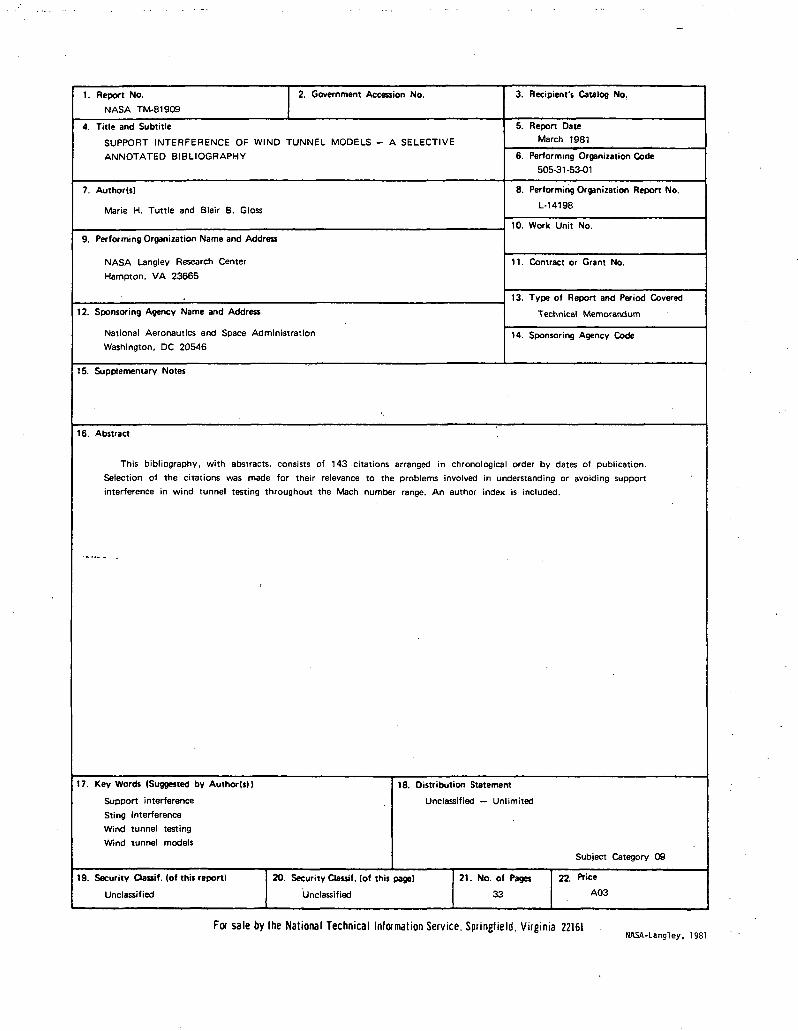
1. Report No.
NASA TM-81909
2. Government Accession No. 3. Recipient's Catalog No.
4. Title and Subtitle
SUPPORT INTERFERENCE OF WIND TUNNEL MODELS - A SELECTIVE
ANNOTATED BIBLIOGRAPHY
5. Report DateMarch 1981
6. Performing Organization Code505-31-53-01
7. Author(s)
Marie H. Tuttle and Blair B. Gloss
8. Performing Organization Report No.
L-14198
10. Work Unit No.9. Performing Organization Name and Address
NASA Langley Research Center
Hampton. VA 2366511. Contract or Grant No.
12. Sponsoring Agency Name and Address
National Aeronautics and Space Administration
Washington, DC 20546
13. Type of Report and Period Covered
Technical Memorandum
14. Sponsoring Agency Code
15. Supplementary Notes
16. Abstract
This bibliography, with abstracts, consists of 143 citations arranged in chronological order by dates of publication.Selection of the citations was made for their relevance to the problems involved in understanding or avoiding support
interference in wind tunnel testing throughout the Mach number range. An author index is included.
17. Key Words (Suggested by Author(s))
Support interference
Sting interferenceWind tunnel testing
Wind tunnel models
18. Distribution Statement
Unclassified — Unlimited
Subject Category 09
19. Security Qasif. (of this report)
Unclassified
20. Security Classif. (of this page)
Unclassified
21. No. of Pages
33
22. Price
A03
For sale by the National Technical Information Service, Springfield. Virginia 22161NASA-Ungley, 1981