Embed Size (px)
Citation preview
SupportingLifeEnvironmental Control and LifeSupport for the Multi-PurposeLogistics Module (MPLM) of theInternational Space Station
B R-143May 1999
Directorate of Manned Spaceflight and MicrogravityDirection des Vols Habités et de la Microgravité
><
Contents
Supporting the International Space Station 4
Living in Space 8Pressure Control 8Temperature and Humidity Control 8Air Contamination Monitoring and Control 8Fire Detection and Suppression 8Water and Waster Management 8
ECLS for MPLM 10Temperature and Humidity Control 10Atmosphere Pressure Control 12
Positive Pressure Relief Assembly 13Negative Pressure Relief Assembly 13Cabin Depressurisation Assembly 14Total Pressure Monitor 14
Fire Detection and Suppression 15Cabin Air Contamination Monitoring and Control 16
Verification of the ECLS Subsystem 17Subsystem Analyses 17
Temperature and Humidity Control 17Depressurisation and Repressurisation Analyses 18Audible Noise Analysis 18Fire Suppression Analyses 18Contamination Monitoring Analysis 19
Subsystem Qualification Tests 19Cabin Ventilation Test 19Hydraulic Test 19Fire Suppression Tests 19
Sharing with Columbus 20
Conclusion 22
Acronyms & Abbreviations 22
ASI: Agenzia Spaziale ItalianaATV: Automated Transfer
Vehicle
CDA: Cabin DepressurisationAssembly
DASA: DaimlerChryslerAerospace
DSD: Duct Smoke Detector
ECLS: Environmental Controland Life Support
EGSE: Electrical GroundSupport Equipment
ESA: European Space Agency
FDS: Fan Damping SystemFM: Flight Model
GSE: Ground SupportEquipment
IMV: Inter Module VentilationISPR: International Standard
Payload RackISS: International Space
Station
LSOV: Line Shut-Off Valve
MGSE: Mechanical GroundSupport Equipment
Acronyms & Abbreviations
MPLM: Multi-Purpose LogisticsModule
NASA: National Aeronauticsand Space Administration
NPRA: Negative PressureRelief Assembly
PFEX: Portable FireExtinguisher
PPRA: Positive Pressure ReliefAssembly
THC: Temperature andHumidity Control
TPM: Total Pressure Monitor
22
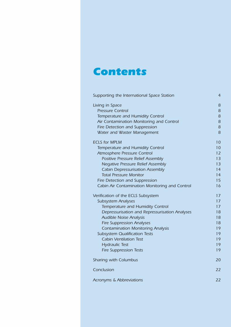
Conclusion
The ECLS Subsystem for MPLM has beensuccessfully developed, and thehardware for three module flight unitsdelivered to ASI. This effort forms part ofthe cooperation between ESA and ASIaimed at improving the overall efficiencyof industrial development for Europe’scontribution to the International SpaceStation.
In exchange for the development ofMPLM’s ECLS Subsystem, the Columbusflight unit primary structure – directlyderived from MPLM’s design – is currently
being manufactured under ASI’sresponsibility. As the requirements for thetwo modules are so similar, the Columbusstructure needs no dedicatedqualification testing.
Considerable savings for both projectshave been achieved by singledevelopment and qualification ofcommon hardware – a significantcontribution to improving theaffordability of manned spaceprogrammes.
BR-143 “Supporting Life” (ISBN 92-9092-633-3)
Written by: Daniele Laurini & Alan Thirkettle,Directorate of Manned Spaceflight and MicrogravityKlaus Bockstahler, DaimlerChrysler Aerospace/Dornier
Edited by: Andrew Wilson, ESA Publications Division
Published by: ESA Publications Division,ESTEC, Noordwijk, The Netherlands
Design: Carel Haakman & Andrew Wilson
Artwork: Willem Versteeg
Price: 20 Dutch Guilders/EUR9
© European Space Agency 1999
4
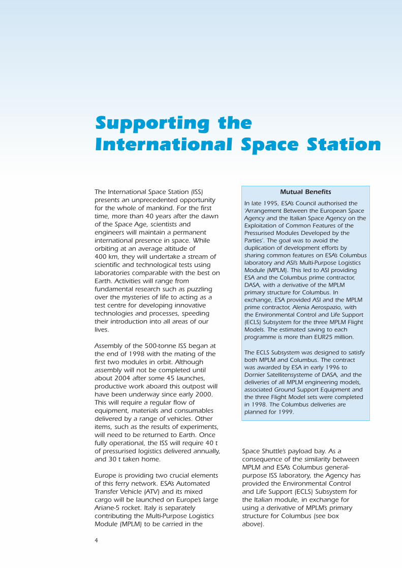
Space Shuttle’s payload bay. As aconsequence of the similarity betweenMPLM and ESA’s Columbus general-purpose ISS laboratory, the Agency hasprovided the Environmental Controland Life Support (ECLS) Subsystem forthe Italian module, in exchange forusing a derivative of MPLM’s primarystructure for Columbus (see boxabove).
Mutual Benefits
In late 1995, ESA’s Council authorised the‘Arrangement Between the European SpaceAgency and the Italian Space Agency on theExploitation of Common Features of thePressurised Modules Developed by theParties’. The goal was to avoid theduplication of development efforts bysharing common features on ESA’s Columbuslaboratory and ASI’s Multi-Purpose LogisticsModule (MPLM). This led to ASI providingESA and the Columbus prime contractor,DASA, with a derivative of the MPLMprimary structure for Columbus. Inexchange, ESA provided ASI and the MPLMprime contractor, Alenia Aerospazio, withthe Environmental Control and Life Support(ECLS) Subsystem for the three MPLM FlightModels. The estimated saving to eachprogramme is more than EUR25 million.
The ECLS Subsystem was designed to satisfyboth MPLM and Columbus. The contractwas awarded by ESA in early 1996 toDornier Satellitensysteme of DASA, and thedeliveries of all MPLM engineering models,associated Ground Support Equipment andthe three Flight Model sets were completedin 1998. The Columbus deliveries areplanned for 1999.
Supporting the International Space Station
The International Space Station (ISS)presents an unprecedented opportunityfor the whole of mankind. For the firsttime, more than 40 years after the dawnof the Space Age, scientists andengineers will maintain a permanentinternational presence in space. Whileorbiting at an average altitude of400 km, they will undertake a stream ofscientific and technological tests usinglaboratories comparable with the best onEarth. Activities will range fromfundamental research such as puzzlingover the mysteries of life to acting as atest centre for developing innovativetechnologies and processes, speedingtheir introduction into all areas of ourlives.
Assembly of the 500-tonne ISS began atthe end of 1998 with the mating of thefirst two modules in orbit. Althoughassembly will not be completed untilabout 2004 after some 45 launches,productive work aboard this outpost willhave been underway since early 2000.This will require a regular flow ofequipment, materials and consumablesdelivered by a range of vehicles. Otheritems, such as the results of experiments,will need to be returned to Earth. Oncefully operational, the ISS will require 40 tof pressurised logistics delivered annually,and 30 t taken home.
Europe is providing two crucial elementsof this ferry network. ESA’s AutomatedTransfer Vehicle (ATV) and its mixedcargo will be launched on Europe’s largeAriane-5 rocket. Italy is separatelycontributing the Multi-Purpose LogisticsModule (MPLM) to be carried in the
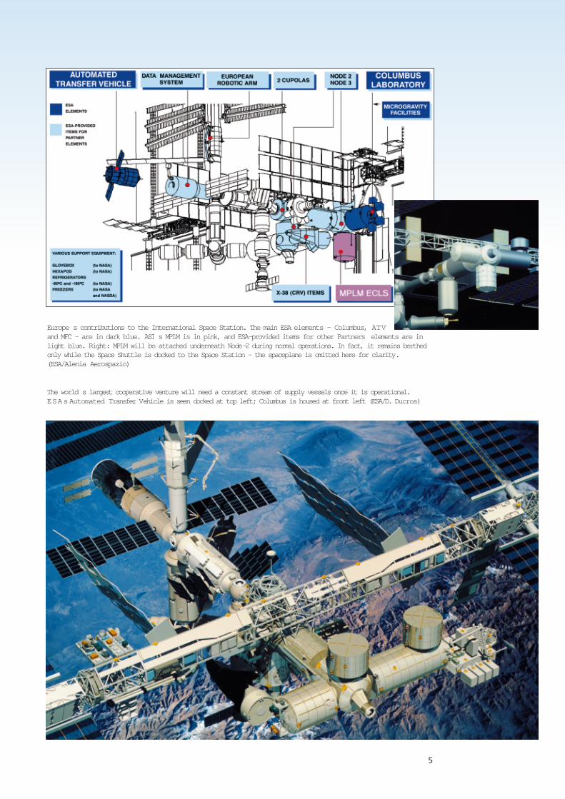
The world s largest cooperative venture will need a constant stream of supply vessels once it is operational.ESAs Automated Transfer Vehicle is seen docked at top left; Columbus is housed at front left (ESA/D. Ducros)
Europe s contributions to the International Space Station. The main ESA elements — Columbus, ATVand MFC — are in dark blue. ASI s MPLM is in pink, and ESA-provided items for other Partners elements are inlight blue. Right: MPLM will be attached underneath Node-2 during normal operations. In fact, it remains berthedonly while the Space Shuttle is docked to the Space Station — the spaceplane is omitted here for clarity.(ESA/Alenia Aerospazio)
5
6
Supplying the ISSThe MPLM programme is the result of abilateral barter between the Italian SpaceAgency and NASA. In exchange for theMPLMs, NASA is providing ASI withexperiment and research opportunitiesaboard the ISS.
MPLM is a unique part of the overall ISSlogistics scenario, which includes NASA’sShuttle, ESA’s ATV, Japan’s H-2 TransferVehicle (HTV), America’s commercialSpacehab (carried aboard Shuttle) andRussia’s Progress and Soyuz vehicles.MPLM is the only logistics modulecapable of transferring completeInternational Standard Payload Racks(ISPRs) to and from the ISS. Not only that,but five of the 16 ISPRs can be suppliedwith power of up to 3 kW in total. Noother ISS ferry can do that. So, forexample, experiment samples can bedelivered to the ISS or returned to Earthstill deeply frozen.
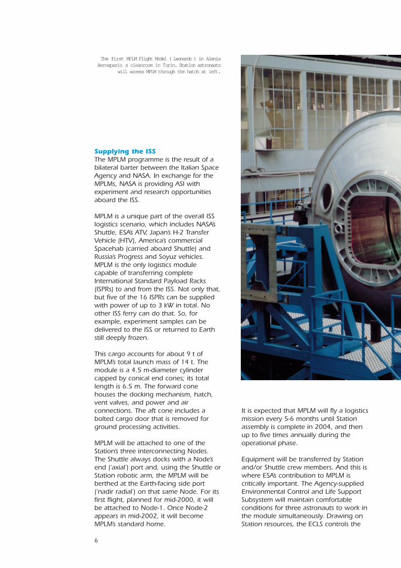
This cargo accounts for about 9 t ofMPLM’s total launch mass of 14 t. Themodule is a 4.5 m-diameter cylindercapped by conical end cones; its totallength is 6.5 m. The forward conehouses the docking mechanism, hatch,vent valves, and power and airconnections. The aft cone includes abolted cargo door that is removed forground processing activities.
MPLM will be attached to one of theStation’s three interconnecting Nodes.The Shuttle always docks with a Node’send (‘axial’) port and, using the Shuttle orStation robotic arm, the MPLM will beberthed at the Earth-facing side port(‘nadir radial’) on that same Node. For itsfirst flight, planned for mid-2000, it willbe attached to Node-1. Once Node-2appears in mid-2002, it will becomeMPLM’s standard home.
It is expected that MPLM will fly a logisticsmission every 5-6 months until Stationassembly is complete in 2004, and thenup to five times annually during theoperational phase.
Equipment will be transferred by Stationand/or Shuttle crew members. And this iswhere ESA’s contribution to MPLM iscritically important. The Agency-suppliedEnvironmental Control and Life SupportSubsystem will maintain comfortableconditions for three astronauts to work inthe module simultaneously. Drawing onStation resources, the ECLS controls the
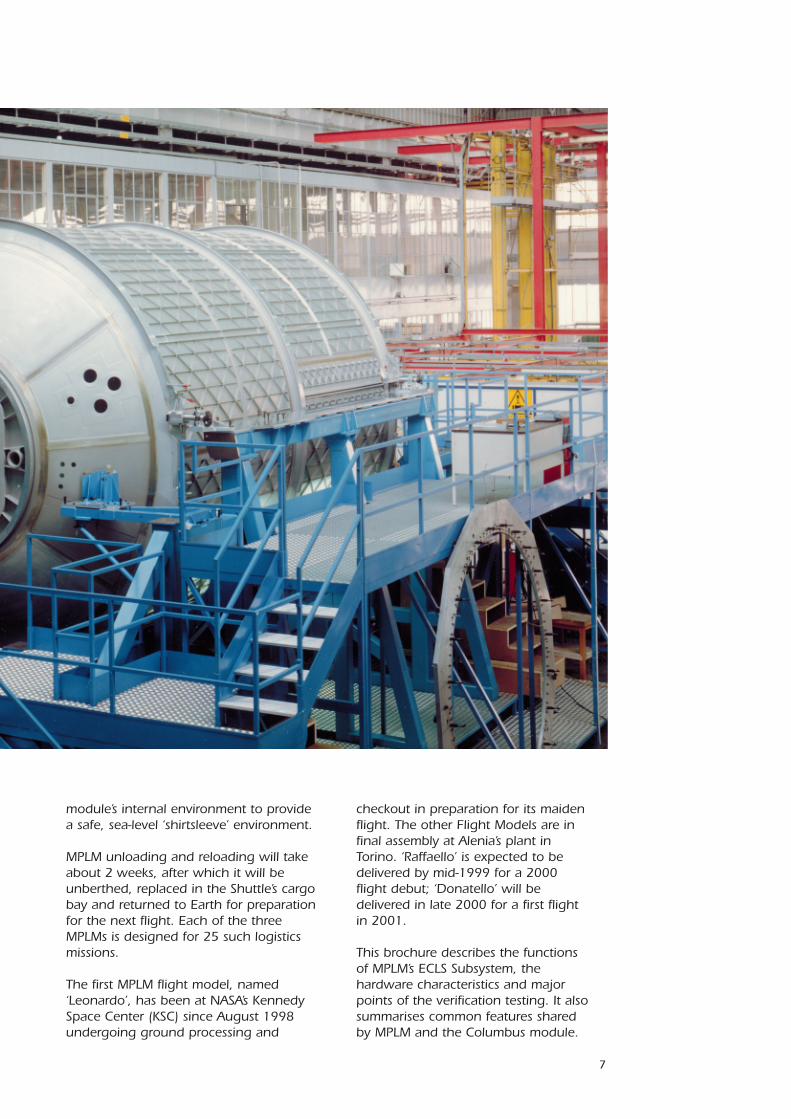
The first MPLM Flight Model ( Leonardo ) in AleniaAerospazio s cleanroom in Turin. Station astronauts
will access MPLM through the hatch at left.
7
module’s internal environment to providea safe, sea-level ‘shirtsleeve’ environment.
MPLM unloading and reloading will takeabout 2 weeks, after which it will beunberthed, replaced in the Shuttle’s cargobay and returned to Earth for preparationfor the next flight. Each of the threeMPLMs is designed for 25 such logisticsmissions.
The first MPLM flight model, named‘Leonardo’, has been at NASA’s KennedySpace Center (KSC) since August 1998undergoing ground processing and
checkout in preparation for its maidenflight. The other Flight Models are infinal assembly at Alenia’s plant inTorino. ‘Raffaello’ is expected to bedelivered by mid-1999 for a 2000flight debut; ‘Donatello’ will bedelivered in late 2000 for a first flightin 2001.
This brochure describes the functionsof MPLM’s ECLS Subsystem, thehardware characteristics and majorpoints of the verification testing. It alsosummarises common features sharedby MPLM and the Columbus module.
8
Living in Space
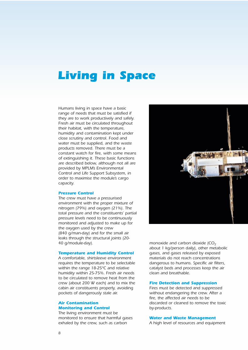
Humans living in space have a basicrange of needs that must be satisfied ifthey are to work productively and safely.Fresh air must be circulated throughouttheir habitat, with the temperature,humidity and contamination kept underclose scrutiny and control. Food andwater must be supplied, and the wasteproducts removed. There must be aconstant watch for fire, with some meansof extinguishing it. These basic functionsare described below, although not all areprovided by MPLM’s EnvironmentalControl and Life Support Subsystem, inorder to maximise the module’s cargocapacity.
Pressure ControlThe crew must have a pressurisedenvironment with the proper mixture ofnitrogen (79%) and oxygen (21%). Thetotal pressure and the constituents’ partialpressure levels need to be continuouslymonitored and adjusted to make up forthe oxygen used by the crew(840 g/man-day) and for the small airleaks through the structural joints (20-40 g/module-day).
Temperature and Humidity ControlA comfortable, shirtsleeve environmentrequires the temperature to be selectablewithin the range 18-25ºC and relativehumidity within 25-75%. Fresh air needsto be circulated to remove heat from thecrew (about 200 W each) and to mix thecabin air constituents properly, avoidingpockets of dangerously stale air.
Air Contamination Monitoring and ControlThe living environment must bemonitored to ensure that harmful gasesexhaled by the crew, such as carbon
monoxide and carbon dioxide (CO2about 1 kg/person daily), other metabolicgases, and gases released by exposedmaterials do not reach concentrationsdangerous to humans. Specific air filters,catalyst beds and processes keep the airclean and breathable.
Fire Detection and SuppressionFires must be detected and suppressedwithout endangering the crew. After afire, the affected air needs to bediscarded or cleaned to remove the toxicby-products.
Water and Waste ManagementA high level of resources and equipment
9
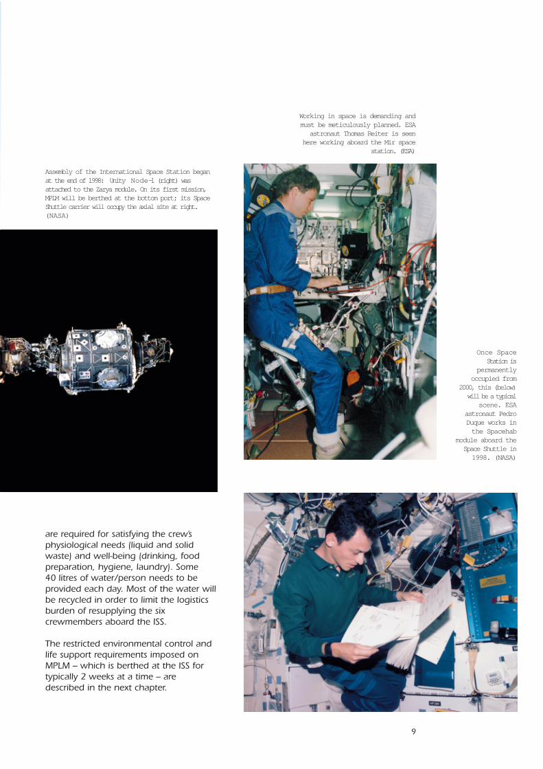
Working in space is demanding andmust be meticulously planned. ESA
astronaut Thomas Reiter is seenhere working aboard the Mir space
station. (ESA)
Assembly of the International Space Station beganat the end of 1998: Unity Node-1 (right) wasattached to the Zarya module. On its first mission,MPLM will be berthed at the bottom port; its SpaceShuttle carrier will occupy the axial site at right.(NASA)
Once SpaceStation is
permanentlyoccupied from
2000, this (below)will be a typical
scene. ESAastronaut PedroDuque works inthe Spacehab
module aboard theSpace Shuttle in1998. (NASA)
are required for satisfying the crew’sphysiological needs (liquid and solidwaste) and well-being (drinking, foodpreparation, hygiene, laundry). Some40 litres of water/person needs to beprovided each day. Most of the water willbe recycled in order to limit the logisticsburden of resupplying the sixcrewmembers aboard the ISS.
The restricted environmental control andlife support requirements imposed onMPLM – which is berthed at the ISS fortypically 2 weeks at a time – aredescribed in the next chapter.
10
ECLS for MPLM
The ESA-supplied Environmental Controland Life Support (ECLS) Subsystem mustprovide comfortable working conditionsinside the MPLM for up to threeastronauts over two weeks. In particular,it must provide:
• Temperature and humidity control;• Atmosphere pressure control;• Fire detection and suppression;• Contamination monitoring and
control.
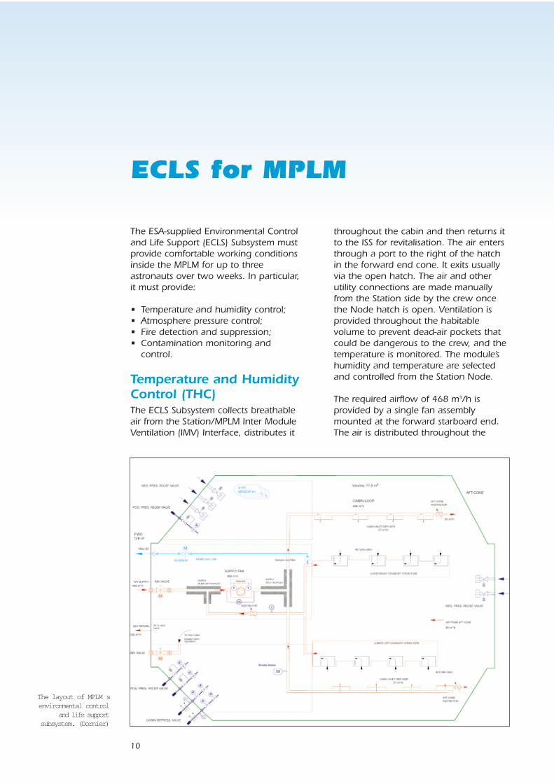
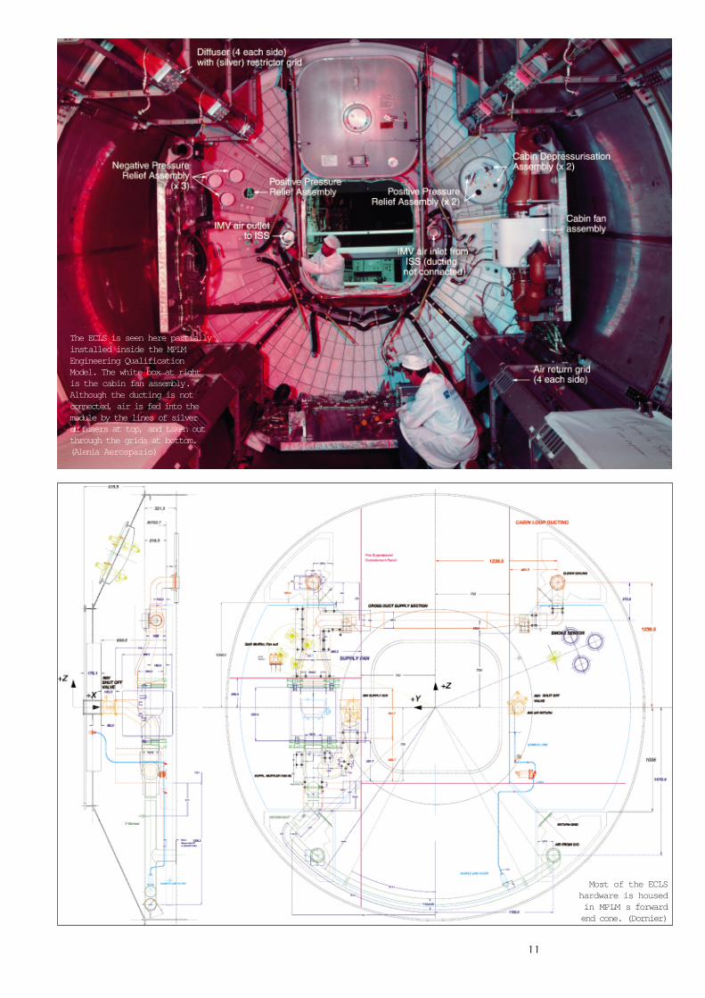
Temperature and HumidityControl (THC)The ECLS Subsystem collects breathableair from the Station/MPLM Inter ModuleVentilation (IMV) Interface, distributes it
throughout the cabin and then returns itto the ISS for revitalisation. The air entersthrough a port to the right of the hatchin the forward end cone. It exits usuallyvia the open hatch. The air and otherutility connections are made manuallyfrom the Station side by the crew oncethe Node hatch is open. Ventilation isprovided throughout the habitablevolume to prevent dead-air pockets thatcould be dangerous to the crew, and thetemperature is monitored. The module’shumidity and temperature are selectedand controlled from the Station Node.
The required airflow of 468 m3/h isprovided by a single fan assemblymounted at the forward starboard end.The air is distributed throughout the
The layout of MPLM senvironmental control
and life supportsubsystem. (Dornier)
11
Most of the ECLShardware is housedin MPLM s forwardend cone. (Dornier)
The ECLS is seen here partiallyinstalled inside the MPLMEngineering QualificationModel. The white box at rightis the cabin fan assembly.Although the ducting is notconnected, air is fed into themodule by the lines of silverdiffusers at top, and taken outthrough the grids at bottom.(Alenia Aerospazio)
12
module by ducting anddiffusers set in twobranches along the uppercabin – four diffusers oneach side, alternating withthe lights. Each diffuseremits about 51 m3/h toproduce the required cabin air movement. Afurther 30 m3/h is routedfrom each branch into theaft cone along the roof.Restrictor grids in thediffusers and restrictors inthe outlets to the aft cone adjust theflows. These are fixed on the ground andcannot be adjusted by the crew, in orderto avoid upsetting the ventilation pattern.If the fan assembly fails, the IMV Interfaceis closed and crew operations in theMPLM are restricted.
The air is sucked from the module viareturn grids in the lower platforms(‘stand-offs’). The two branches are mixedin a junction duct and led back to thefan inlet, where the Station supply isadded. A restrictor in the return duct
ensures the pressure islower than at the IMVsupply interface, so aircontinues to be suckedfrom the Station.
Normally, air flows backto the Station through theopen 40-inch (102 cm)hatch. If the hatch isclosed, the air travelsthrough the separatededicated IMV returnduct. To isolate the
module from the Station, a motorisedvalve in each of the IMV supply andreturn ducts closes off the airflow.
A sensor in the return duct measurescabin temperature with an accuracy of±0.5°C. The signal is supplied to theMPLM data acquisition and managementsystem for transmission to the ground,where it triggers a warning if it straysbeyond pre-set limits.
In order to reduce airborne noise fromthe cabin fan, duct mufflers are includedon the fan inlet and outlet sides. Anacoustic box encloses the fan casing toattenuate the radiated noise.
Atmosphere PressureControlThe total atmospheric pressure ismonitored, and the ECLS Subsystemtransmits an emergency signal to the ISSif MPLM’s air pressure climbs or fallsbeyond pre-set limits. The module canalso be depressurised rapidly in theevent, for example, of a fire.
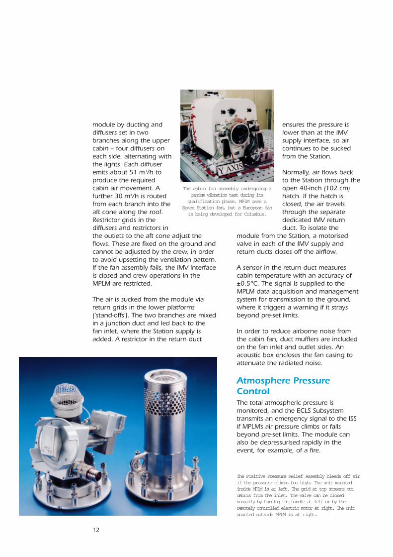
The Positive Pressure Relief Assembly bleeds off airif the pressure climbs too high. The unit mountedinside MPLM is at left. The grid at top screens outdebris from the inlet. The valve can be closedmanually by turning the handle at left or by theremotely-controlled electric motor at right. The unitmounted outside MPLM is at right.
The cabin fan assembly undergoing arandom vibration test during its
qualification phase. MPLM uses aSpace Station fan, but a European fanis being developed for Columbus.
13
Positive Pressure Relief AssemblyMPLM’s structure is designed to handle apressure differential (the differencebetween internal and external pressure)of 1.034 Earth-atmospheres (1048 hPa).To prevent it from reaching this level, thevalve in the Positive Pressure ReliefAssembly (PPRA) opens and vents airfrom the cabin when the pressuredifferential rises to 1.014 atm (1027 hPa).This ‘crack pressure’ can be reachedwhen the MPLM is isolated, for example,inside the Shuttle during launch, whenthe internal temperature might increasebecause equipment is powered upwithout active cooling.
The assembly provides ‘two-failuretolerance’ by using three valves inparallel, any one of which can do thejob. Two are housed in a feed-throughplate in the upper area of the forwardcone; the third is mounted directly in thecone’s lower area.
Each assembly comprises a power-independent pneumatic pressure reliefvalve and a butterfly shut-off valve,installed in series. The shut-off valve canbe closed electrically by a brush-type28 Vdc motor or by manual override; thisisolates the assembly in case thepneumatic relief valve or motor fail.
Ground controllers or Space Stationcrews can use the electric motors todeactivate the system when it is notrequired. For example, when MPLM isdocked with its hatch open and theStation is providing overall pressurecontrol.
Each outlet minimises the thrust itgenerates during venting by directing theair through holes distributed equallyaround the circumference. On the inside,a debris screen protects each assembly’sair inlet to avoid valve contaminationfrom particles floating in the cabin airand to prevent their release into space.
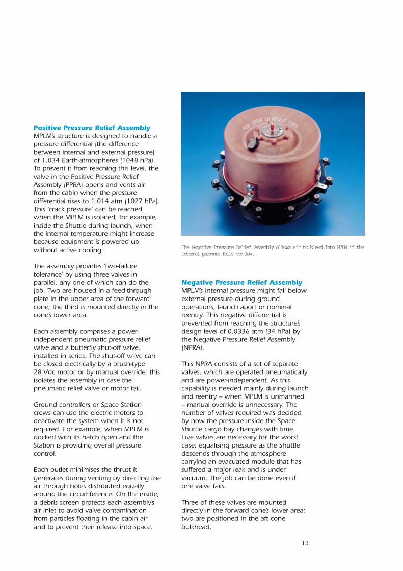
Negative Pressure Relief AssemblyMPLM’s internal pressure might fall belowexternal pressure during groundoperations, launch abort or nominalreentry. This negative differential isprevented from reaching the structure’sdesign level of 0.0336 atm (34 hPa) bythe Negative Pressure Relief Assembly(NPRA).
This NPRA consists of a set of separatevalves, which are operated pneumaticallyand are power-independent. As thiscapability is needed mainly during launchand reentry – when MPLM is unmanned– manual override is unnecessary. Thenumber of valves required was decidedby how the pressure inside the SpaceShuttle cargo bay changes with time.Five valves are necessary for the worstcase: equalising pressure as the Shuttledescends through the atmospherecarrying an evacuated module that hassuffered a major leak and is undervacuum. The job can be done even ifone valve fails.
Three of these valves are mounteddirectly in the forward cone’s lower area;two are positioned in the aft conebulkhead.
The Negative Pressure Relief Assembly allows air to bleed into MPLM if theinternal pressure falls too low.
14
Each valve is protected externally by adebris screen. The redundant cover isone-failure tolerant against leakage tospace during nominal on-orbit missionphases, when the pneumatic portion ofthe valve is not needed. This phase canlast up to 15 years for the Columbusmodule.
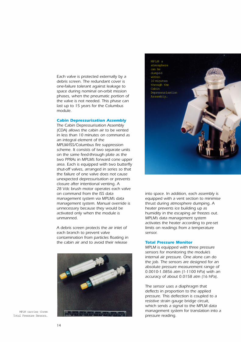
Cabin Depressurisation AssemblyThe Cabin Depressurisation Assembly(CDA) allows the cabin air to be ventedin less than 10 minutes on command asan integral element of theMPLM/ISS/Columbus fire suppressionscheme. It consists of two separate unitson the same feed-through plate as thetwo PPRAs in MPLM’s forward cone upperarea. Each is equipped with two butterflyshut-off valves, arranged in series so thatthe failure of one valve does not causeunexpected depressurisation or preventsclosure after intentional venting. A28 Vdc brush motor operates each valveon command from the ISS datamanagement system via MPLM’s datamanagement system. Manual override isunnecessary because they would beactivated only when the module isunmanned.
A debris screen protects the air inlet ofeach branch to prevent valvecontamination from particles floating inthe cabin air and to avoid their release
into space. In addition, each assembly isequipped with a vent section to minimisethrust during atmosphere dumping. Aheater prevents ice building up ashumidity in the escaping air freezes out.MPLM’s data management systemactivates the heater according to pre-setlimits on readings from a temperaturesensor.
Total Pressure MonitorMPLM is equipped with three pressuresensors for monitoring the module’sinternal air pressure. One alone can dothe job. The sensors are designed for anabsolute pressure measurement range of0.0010-1.0856 atm (1-1100 hPa) with anaccuracy of about 0.0158 atm (16 hPa).
The sensor uses a diaphragm thatdeflects in proportion to the appliedpressure. This deflection is coupled to aresistive strain gauge bridge circuit,which sends a signal to the MPLM datamanagement system for translation into apressure reading.
MPLM carries threeTotal Pressure Sensors.
MPLM satmosphere can be dumped within10 minutesthrough theCabinDepressurisationAssembly.
15
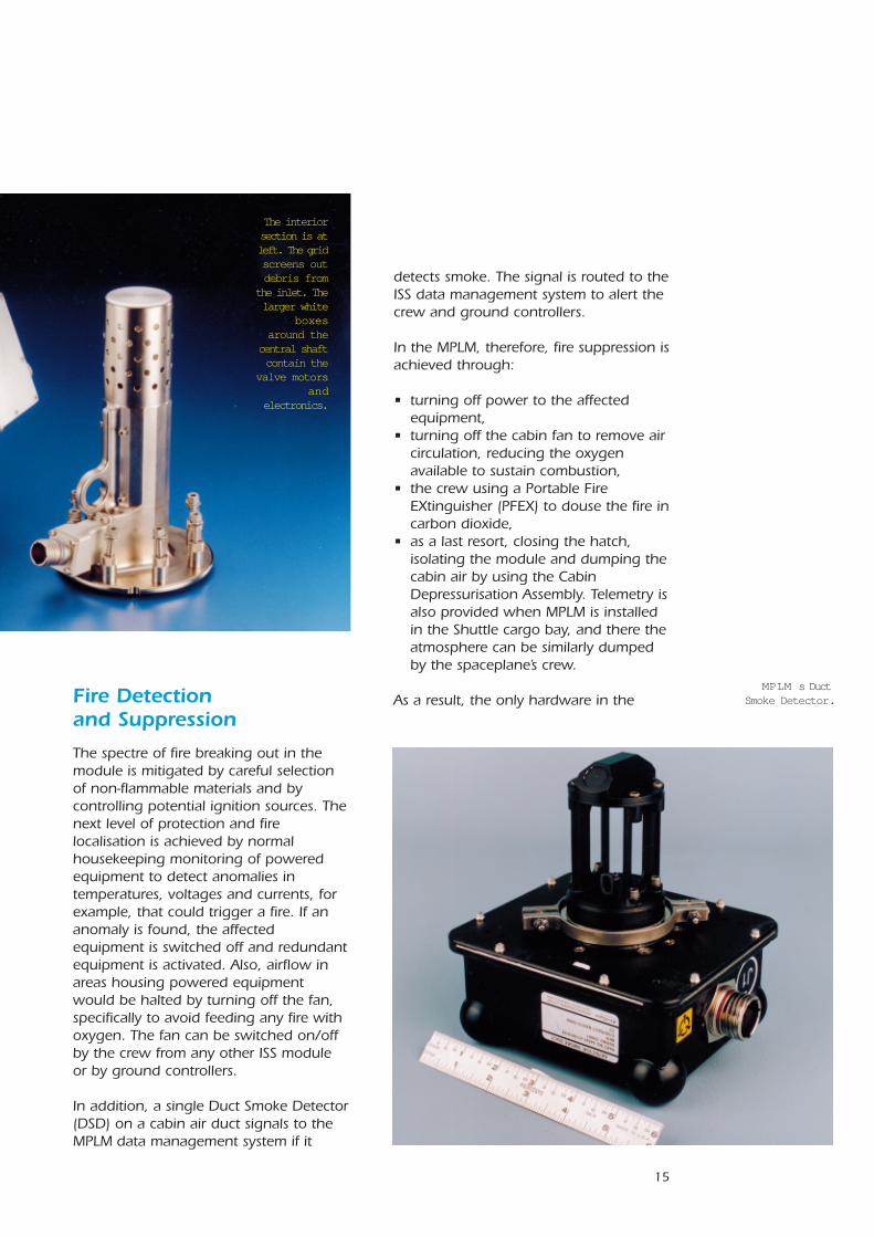
MPLM s DuctSmoke Detector.Fire Detection
and Suppression
The spectre of fire breaking out in themodule is mitigated by careful selectionof non-flammable materials and bycontrolling potential ignition sources. Thenext level of protection and firelocalisation is achieved by normalhousekeeping monitoring of poweredequipment to detect anomalies intemperatures, voltages and currents, forexample, that could trigger a fire. If ananomaly is found, the affectedequipment is switched off and redundantequipment is activated. Also, airflow inareas housing powered equipmentwould be halted by turning off the fan,specifically to avoid feeding any fire withoxygen. The fan can be switched on/offby the crew from any other ISS moduleor by ground controllers.
In addition, a single Duct Smoke Detector(DSD) on a cabin air duct signals to theMPLM data management system if it
detects smoke. The signal is routed to theISS data management system to alert thecrew and ground controllers.
In the MPLM, therefore, fire suppression isachieved through:
• turning off power to the affectedequipment,
• turning off the cabin fan to remove aircirculation, reducing the oxygenavailable to sustain combustion,
• the crew using a Portable FireEXtinguisher (PFEX) to douse the fire incarbon dioxide,
• as a last resort, closing the hatch,isolating the module and dumping thecabin air by using the CabinDepressurisation Assembly. Telemetry isalso provided when MPLM is installedin the Shuttle cargo bay, and there theatmosphere can be similarly dumpedby the spaceplane’s crew.
As a result, the only hardware in the
The interiorsection is atleft. The gridscreens outdebris from
the inlet. Thelarger white
boxesaround the
central shaftcontain the
valve motorsand
electronics.

16
MPLM supporting fire detection andsuppression is:
• one smoke sensor installed in thecabin loop duct downstream of thecabin fan, thus covering the cabin,aft cone and lower stand-offvolumes,
• a portable fire extinguisher forfighting fires in the forward endcone where most of MPLM’spowered equipment is located. Thatarea is divided into threecompartments, each with a volumeso that the carbon dioxide from asingle extinguisher would reducethe oxygen concentration below theminimum (10.5% by volume)necessary for sustaining a fire.
Cabin Air ContaminationMonitoring and ControlThe atmosphere in any mannedspacecraft must be continuouslymonitored to ensure it is wholesome –the proper mix and free of poisonoustraces. In MPLM’s case, the cabin air’smajor constituents and trace gascontamination are measured by theStation’s ECLS equipment. Periodicsamples of the cabin return air are
drawn into the Station via a dedicatedtube.
The sampling line consists of a1/4-inch (0.635 mm) diameter tubeconnected at one end to the cabin airreturn duct upstream of the cabin fan,and at the other end to the forwardcone bulkhead. At the cabin end, aparticle filter (mesh size 2 µm) screensout debris. The connection to theStation is made manually after theNode hatch is opened. A Line Shut-OffValve (LSOV) isolates the line from theStation. It is normally operatedelectrically by a 28 Vdc brush-typemotor, but it is equipped with amanual override in case of motorfailure. The crew opens it duringMPLM activation procedures, and closeit before the return to Earth.
The Line Shut-Off Valveisolates the air sampling
tube between MPLMand the Station.
17
Verification of the ECLS Subsystem
The second operational mode entails aclosed hatch, such as during MPLMactivation after berthing or when thecrew leaves it unoccupied for lengthyperiods. The IMV return air is now routedback to the Node via a dedicated returnduct beside the hatch through theberthing face. Since the fan is controlledto run at a constant speed, the loopmoves to a new performance point. Thepressure level in the MPLM increases toabout 210 Pa above Node level in orderto overcome the pressure drop in the IMVreturn duct. The IMV exchange airreduces to 180 m3/h and the overallventilated air reduces from 468 m3/h to425 m3/h because of the increasedpressure rise required of the fan.
In order to qualify the design of theoverall ECLS Subsystem and thehardware described in the previouschapter, a mixture of subsystem andequipment analyses and tests wasperformed.
Subsystem AnalysesTemperature and Humidity ControlMPLM’s ECLS Subsystem cabin loop wasmodelled and hydraulic calculations wereperformed to simulate loop performanceand to predefine the cabin fan setting.ESA’s ECOSIM software tool was used forthe loop modelling.
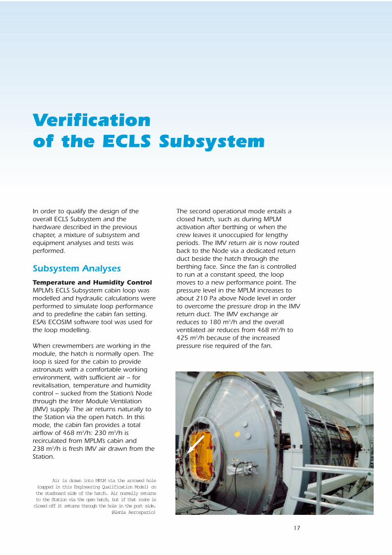
When crewmembers are working in themodule, the hatch is normally open. Theloop is sized for the cabin to provideastronauts with a comfortable workingenvironment, with sufficient air – forrevitalisation, temperature and humiditycontrol – sucked from the Station’s Nodethrough the Inter Module Ventilation(IMV) supply. The air returns naturally tothe Station via the open hatch. In thismode, the cabin fan provides a totalairflow of 468 m3/h: 230 m3/h isrecirculated from MPLM’s cabin and238 m3/h is fresh IMV air drawn from theStation.
Air is drawn into MPLM via the arrowed hole(capped in this Engineering Qualification Model) onthe starboard side of the hatch. Air normally returnsto the Station via the open hatch, but if that route isclosed off it returns through the hole in the port side.
(Alenia Aerospazio)
18
The third operational mode has a closedhatch and IMV, which occurs whenMPLM is in the Shuttle cargo bay on anactive mission (refrigerator/freezers arebeing launched or returned). In thismode, the module is isolated and onlyinternal ventilation is maintained toprovide fire detection. With the fan speedkept constant, the total ventilated air is306 m3/h in this mode.
Depressurisation and Repressurisation AnalysesDifferent analyses were performed for therepressurisation and depressurisationprocesses in order to size the valvesrequired and to define the number ofbranches for the negative and positivepressure relief assemblies and the cabindepressurisation assembly. The need for acommon MPLM/Columbus design meantthe equipment has to cope with bothmodules and their differences, such asfree volume and temperatures.
The venting to space for the CabinDepressurisation Assembly was studiedfor sizing the heaters. These have toprevent ice building up as the humid airvents. Also, a low-thrust vent had to bedesigned for the CDA and the PositivePressure Relief Assembly, to avoiddisturbing forces being generated. A testduring the equipment qualification phaseproved the design.
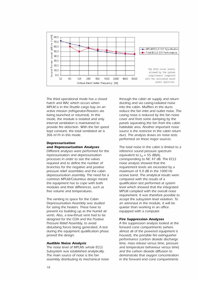
Audible Noise AnalysisThe noise level of MPLM’s whole ECLSSubsystem was established analytically.The main source of noise is the fanassembly distributing its mechanical noise
through the cabin air supply and returnducting and via casing-radiated noiseinto the cabin. Mufflers in the ductsreduce the fan inlet and outlet noise. Thecasing noise is reduced by the fan noisecover and from some damping by thepanels separating the fan from the cabinhabitable area. Another important noisesource is the restrictor in the cabin returnduct. The analysis draws on noise testsperformed on these major sources.
The total noise in the cabin is limited to areference sound pressure spectrumequivalent to LA = 55 dB(A),corresponding to NC 47 dB. The ECLSnoise analysis showed that therequirement levels are exceeded by amaximum of 4.0 dB in the 1000 Hzoctave band. The analytical results werecompared with the results of aqualification test performed at systemlevel which showed that the integratedMPLM complied with the overall noiserequirement. It was therefore possible toaccept the subsystem level violation. Toan astronaut in the module, it will bequieter than working in an officeequipped with a computer.
Fire Suppression AnalysesA fire suppression analysis looked at theforward cone compartments (wherealmost all of the powered equipment ishoused), the portable fire extinguisherperformance (carbon dioxide dischargetime, mass release versus time, pressureand temperature behaviour versus time)and the carbon dioxide diffusion todemonstrate that oxygen concentrationin the forward end cone compartments
The ECLS noise levelsallowed by the systemrequirement compared
with the calculated soundpower spectrum.
19
can be reduced to the required 10.5% byvolume in less than 1 minute. This wasconfirmed by the fire suppressionqualification test.
Contamination Monitoring Analysis A pressure drop analysis in the trace gassampling line defined the line’s filterperformance and established therequired sampling airflow through theline during the filter’s lifetime.
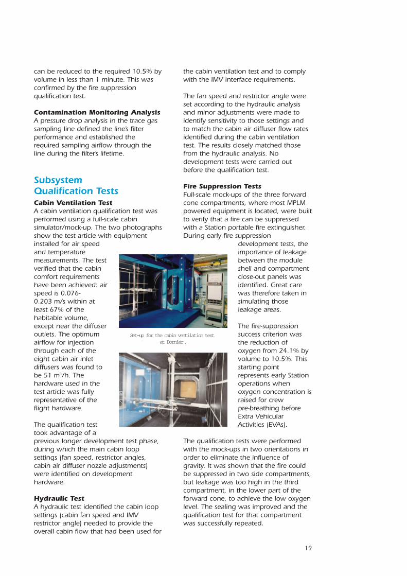
Subsystem Qualification TestsCabin Ventilation TestA cabin ventilation qualification test wasperformed using a full-scale cabinsimulator/mock-up. The two photographsshow the test article with equipmentinstalled for air speedand temperaturemeasurements. The testverified that the cabincomfort requirementshave been achieved: airspeed is 0.076-0.203 m/s within atleast 67% of thehabitable volume,except near the diffuseroutlets. The optimumairflow for injectionthrough each of theeight cabin air inletdiffusers was found tobe 51 m3/h. Thehardware used in thetest article was fullyrepresentative of theflight hardware.
The qualification testtook advantage of aprevious longer development test phase,during which the main cabin loopsettings (fan speed, restrictor angles,cabin air diffuser nozzle adjustments)were identified on developmenthardware.
Hydraulic TestA hydraulic test identified the cabin loopsettings (cabin fan speed and IMVrestrictor angle) needed to provide theoverall cabin flow that had been used for
the cabin ventilation test and to complywith the IMV interface requirements.
The fan speed and restrictor angle wereset according to the hydraulic analysisand minor adjustments were made toidentify sensitivity to those settings andto match the cabin air diffuser flow ratesidentified during the cabin ventilationtest. The results closely matched thosefrom the hydraulic analysis. Nodevelopment tests were carried outbefore the qualification test.
Fire Suppression TestsFull-scale mock-ups of the three forwardcone compartments, where most MPLMpowered equipment is located, were builtto verify that a fire can be suppressedwith a Station portable fire extinguisher.During early fire suppression
development tests, theimportance of leakagebetween the moduleshell and compartmentclose-out panels wasidentified. Great carewas therefore taken insimulating thoseleakage areas.
The fire-suppressionsuccess criterion wasthe reduction ofoxygen from 24.1% byvolume to 10.5%. Thisstarting pointrepresents early Stationoperations whenoxygen concentration israised for crewpre-breathing beforeExtra VehicularActivities (EVAs).
The qualification tests were performedwith the mock-ups in two orientations inorder to eliminate the influence ofgravity. It was shown that the fire couldbe suppressed in two side compartments,but leakage was too high in the thirdcompartment, in the lower part of theforward cone, to achieve the low oxygenlevel. The sealing was improved and thequalification test for that compartmentwas successfully repeated.
Set-up for the cabin ventilation testat Dornier.
20
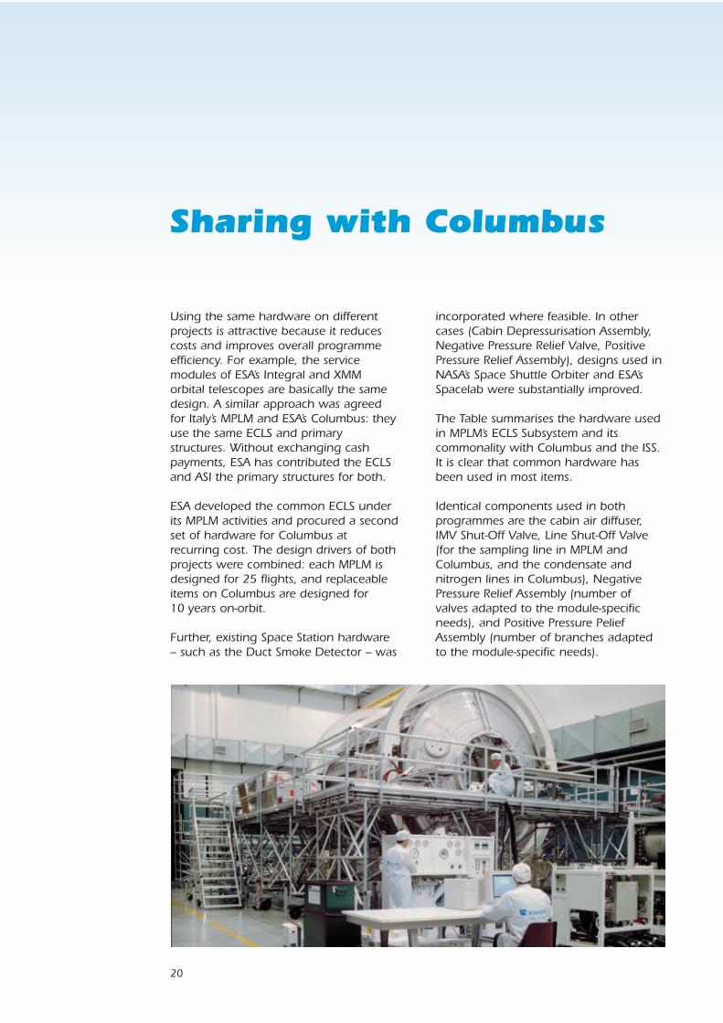
Sharing with Columbus
incorporated where feasible. In othercases (Cabin Depressurisation Assembly,Negative Pressure Relief Valve, PositivePressure Relief Assembly), designs used inNASA’s Space Shuttle Orbiter and ESA’sSpacelab were substantially improved.
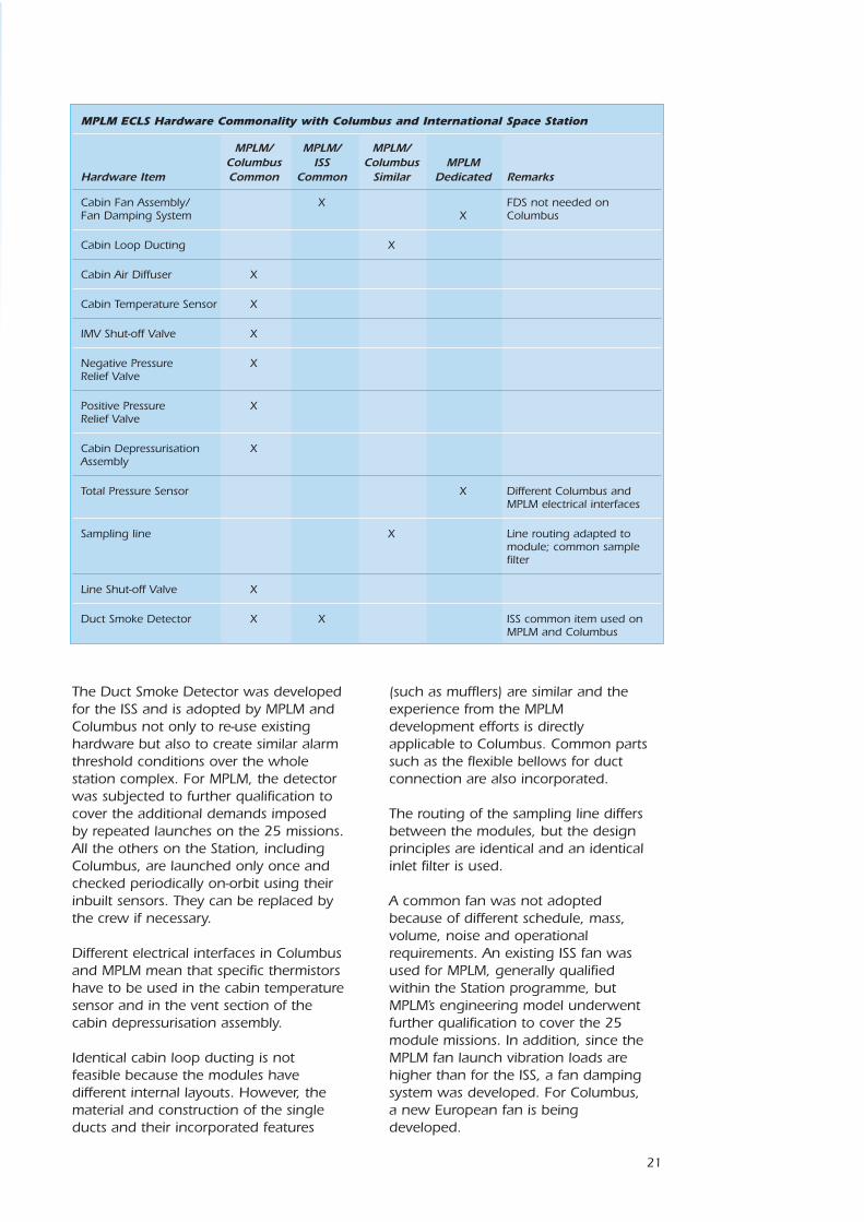
The Table summarises the hardware usedin MPLM’s ECLS Subsystem and itscommonality with Columbus and the ISS.It is clear that common hardware hasbeen used in most items.
Identical components used in bothprogrammes are the cabin air diffuser,IMV Shut-Off Valve, Line Shut-Off Valve(for the sampling line in MPLM andColumbus, and the condensate andnitrogen lines in Columbus), NegativePressure Relief Assembly (number ofvalves adapted to the module-specificneeds), and Positive Pressure PeliefAssembly (number of branches adaptedto the module-specific needs).
Using the same hardware on differentprojects is attractive because it reducescosts and improves overall programmeefficiency. For example, the servicemodules of ESA’s Integral and XMMorbital telescopes are basically the samedesign. A similar approach was agreedfor Italy’s MPLM and ESA’s Columbus: theyuse the same ECLS and primarystructures. Without exchanging cashpayments, ESA has contributed the ECLSand ASI the primary structures for both.
ESA developed the common ECLS underits MPLM activities and procured a secondset of hardware for Columbus atrecurring cost. The design drivers of bothprojects were combined: each MPLM isdesigned for 25 flights, and replaceableitems on Columbus are designed for10 years on-orbit.
Further, existing Space Station hardware– such as the Duct Smoke Detector – was
21
The Duct Smoke Detector was developedfor the ISS and is adopted by MPLM andColumbus not only to re-use existinghardware but also to create similar alarmthreshold conditions over the wholestation complex. For MPLM, the detectorwas subjected to further qualification tocover the additional demands imposedby repeated launches on the 25 missions.All the others on the Station, includingColumbus, are launched only once andchecked periodically on-orbit using theirinbuilt sensors. They can be replaced bythe crew if necessary.
Different electrical interfaces in Columbusand MPLM mean that specific thermistorshave to be used in the cabin temperaturesensor and in the vent section of thecabin depressurisation assembly.
Identical cabin loop ducting is notfeasible because the modules havedifferent internal layouts. However, thematerial and construction of the singleducts and their incorporated features
MPLM ECLS Hardware Commonality with Columbus and International Space Station
MPLM/ MPLM/ MPLM/Columbus ISS Columbus MPLM
Hardware Item Common Common Similar Dedicated Remarks
Cabin Fan Assembly/ X FDS not needed onFan Damping System X Columbus
Cabin Loop Ducting X
Cabin Air Diffuser X
Cabin Temperature Sensor X
IMV Shut-off Valve X
Negative Pressure XRelief Valve
Positive Pressure XRelief Valve
Cabin Depressurisation XAssembly
Total Pressure Sensor X Different Columbus and MPLM electrical interfaces
Sampling line X Line routing adapted tomodule; common samplefilter
Line Shut-off Valve X
Duct Smoke Detector X X ISS common item used onMPLM and Columbus
(such as mufflers) are similar and theexperience from the MPLMdevelopment efforts is directlyapplicable to Columbus. Common partssuch as the flexible bellows for ductconnection are also incorporated.
The routing of the sampling line differsbetween the modules, but the designprinciples are identical and an identicalinlet filter is used.
A common fan was not adoptedbecause of different schedule, mass,volume, noise and operationalrequirements. An existing ISS fan wasused for MPLM, generally qualifiedwithin the Station programme, butMPLM’s engineering model underwentfurther qualification to cover the 25module missions. In addition, since theMPLM fan launch vibration loads arehigher than for the ISS, a fan dampingsystem was developed. For Columbus,a new European fan is beingdeveloped.