Embed Size (px)
Citation preview

Supporting Report 2:Dam Design
MOOI-MGENI RIVER TRANSFER SCHEME
PHASE 2: FEASIBILITY STUDY
goba moahloli keeve steynconsulting engineers & project managers
(pty) ltd
hr africaConsulting Engineers & Project Managers
CONSULTING
in associationwith
DEPARTMENT OF WATER AFFAIRS AND FORESTRYDirectorate: Project Planning
Report No. PB V200-00-1701
FINAL
JANUARY 2004

MOOI-MGENI RIVER TRANSFER SCHEME PHASE 2: FEASIBILITY STUDY
Dam Design Report Page i January 2004 I:\3889\Documents\Feasibility Report\Report 2 _ Dam Design\SGD Design Report January 2004.doc
STRUCTURE OF THE STUDY REPORTS
SUPPORTING REPORT 1WATER RESOURCE ANALYSIS
PB V200/00/1601
SUPPORTING REPORT 2DAM DESIGN
PB V200/00/1701
SUPPORTING REPORT 3TRANSFER INFRASTRUCTURE
PB V200/00/1801
SUPPORTING REPORT 7BIOPHYSICAL
IMPACT ASSESSMENTPB V200/00/2201
SUPPORTING REPORT 8SOCIAL IMPACTASSESSMENT
PB V200/00/2301
SUPPORTING REPORT 9CONCEPTUAL
MANAGEMENT PLANPB V200/00/2401
SUPPORTING REPORT10RECORD OF PUBLIC
INVOLVEMENTPB V200/00/2501
SUPPORTING REPORT 4ENVIRONMENTAL IMPACT
ASSESSMENTPB V200/00/1901
SUPPORTING REPORT 5WATER QAULITYPB V200/00/2001
SUPPORTING REPORT 6COSTING & ENGINEERING
ECONOMICSPB V200/00/2101
MAIN REPORTPB V200/00/1501
LIST OF STUDY REPORTS
Report No. Description Title
PB V200/00/270 Inception Report
PB V200/00/1501 Feasibility Study Main Report
PB V200/00/1601 Supporting Report 1 Water Resource Analysis
PB V200/00/1701 Supporting Report 2 Dam Design PB V200/00/1801 Supporting Report 3 Transfer Infrastructure
PB V200/00/1901 Supporting Report 4 Environmental Impact Assessment
PB V200/00/2001 Supporting Report 5 Water Quality
PB V200/00/2101 Supporting Report 6 Costing & Engineering Economic Analysis
PB V200/00/2201 Supporting Report 7 Biophysical Impact Assessment
PB V200/00/2301 Supporting Report 8 Social Impact Assessment
PB V200/00/2401 Supporting Report 9 Conceptual Management Plan
PB V200/00/2501 Supporting Report 10 Record of Public Involvement This report is to be referred to in Bibliographies as: Department of Water Affairs & Forestry/Umgeni Water 2002. Mooi-Mgeni Transfer Scheme Phase 2: Feasibility Study Supporting Report No.2 - Dam Design. Prepared by DWAF Directorate Civil Design. PB V200 /00/1701 This report was prepared by: DWAF Directorate in association with A.W. van Taak – Pr Eng Civil Design Goba Moaholi Keeve Steyn (Pty) Ltd
MOOI-MGENI RIVER TRANSFER SCHEME PHASE 2: FEASIBILITY STUDY
Dam Design Report Page ii January 2004 I:\3889\Documents\Feasibility Report\Report 2 _ Dam Design\SGD Design Report January 2004.doc
MOOI-MGENI TRANSFER SCHEME PHASE 2
FEASIBILITY STUDY
DAM DESIGN REPORT
EXECUTIVE SUMMARY
The Directorate Project Planning requested Directorate Civil Design to provide them with a feasibility level design and cost estimate for the proposed Spring Grove Dam, as part of Phase II of the Mooi-Mgeni River Transfer Scheme (MMTS-2) Feasibility Study. The proposed Mooi-Mgeni River Transfer Scheme (MMTS) is located in the Midlands of the Province of KwaZulu – Natal. Its objective is to increase the yield and the assurance of supply of the Mgeni River System by diverting water from the Mooi River catchment to Midmar Dam on the Mgeni River. The MMTS is planned in two phases. This report deals with the feasibility design of the proposed Spring Grove Dam, as part of Phase II of the MMTS. The proposed Spring Grove Dam was designed for the final height (no provision for future raising) and includes the following design aspects: • Site details; • Hydrology; • Spillway; • Selection of FSL; • Dam type selection; • Stability analyses; • Outlet works; • Construction; • Dam safety aspects; • Realignment of services; and • Operational requirements. The following three options were considered for a full supply level of 1435,00m.a.s.l. (note that the FSL was changed from 1435,00m.a.s.l. to 1433,50m.a.s.l. at the end of the feasibility design and the design calculations were not revised): • Option 1: A composite rollcrete gravity / embankment dam, with a rollcrete spillway
and earth fill on the right flank. • Option 2: An earth fill dam with a rollcrete central trough spillway in the river
section. • Option 3: A rollcrete gravity dam. These three options were compared on the basis of their estimated costs, and Option 1 was found to be the most economical. In accordance with DWAF standard policy, the proposed Spring Grove Dam will be equipped with easily accessible, reliable, safe and easily maintained outlet works, that assure the release into the downstream river course and pumping station of water of adequate quantity and quality.
MOOI-MGENI RIVER TRANSFER SCHEME PHASE 2: FEASIBILITY STUDY
Dam Design Report Page iii January 2004 I:\3889\Documents\Feasibility Report\Report 2 _ Dam Design\SGD Design Report January 2004.doc
The outlet works is to be located on the right flank and consists of a right-hand and a left-hand portion. The right-hand portion houses the pumping station outlets and the left-hand houses the river outlets. When Spring Grove Dam has been constructed, it needs to be able to release sufficient water so that the March freshette of 40m³/s as measured at Mearns Weir can be achieved. The contribution from the Little Mooi River needs to be taken into account so as to limit releases from Spring Grove Dam. The need to construct new gauging stations on the Little Mooi River must be addressed at the implementation stage. A proposed construction programme is contained in Annexure E of this report. This programme will however be likely to change during the final design stage as well as due to the foreseen budget allocation for construction purposes. Dam safety in the Republic of South Africa is implemented and regulated in terms of sections 117 to 123 (Chapter 12) of the National Water Act (Act No. 36 of 1998) as well as the Regulations in Government Notice R.1560 of 25 July 1986. Dam owners, including the State, are liable for their dams and have to comply with the regulations. The proposed Spring Grove Dam is classified as a Category III dam and the aforementioned applicable dam safety regulations Category III dams will therefore apply.
The estimated cost for the proposed Spring Grove Dam is R 145,5 million and is based on April 2001 rates. Note that this cost excludes social and environmental costs such as relocation costs.
The validity of the feasibility design performed by Civil Design cannot be guaranteed for final construction, and it should only serve as a guideline for the future design team. It must not be used for construction purposes.
MOOI-MGENI RIVER TRANSFER SCHEME PHASE 2: FEASIBILITY STUDY
Dam Design Report Page iv January 2004 I:\3889\Documents\Feasibility Report\Report 2 _ Dam Design\SGD Design Report January 2004.doc
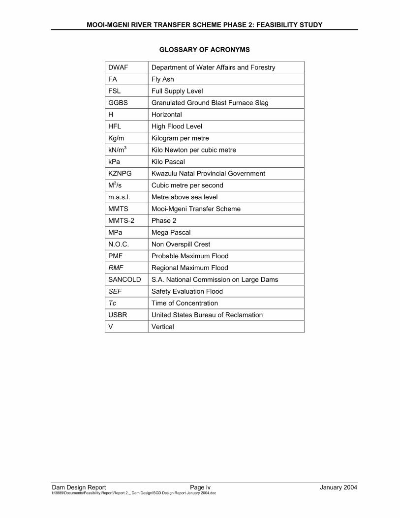
GLOSSARY OF ACRONYMS
DWAF Department of Water Affairs and Forestry
FA Fly Ash
FSL Full Supply Level
GGBS Granulated Ground Blast Furnace Slag
H Horizontal
HFL High Flood Level
Kg/m Kilogram per metre
kN/m3 Kilo Newton per cubic metre
kPa Kilo Pascal
KZNPG Kwazulu Natal Provincial Government
M3/s Cubic metre per second
m.a.s.l. Metre above sea level
MMTS Mooi-Mgeni Transfer Scheme
MMTS-2 Phase 2
MPa Mega Pascal
N.O.C. Non Overspill Crest
PMF Probable Maximum Flood
RMF Regional Maximum Flood
SANCOLD S.A. National Commission on Large Dams
SEF Safety Evaluation Flood
Tc Time of Concentration
USBR United States Bureau of Reclamation
V Vertical
MOOI-MGENI RIVER TRANSFER SCHEME PHASE 2: FEASIBILITY STUDY
Dam Design Report Page 1 January 2004 I:\3889\Documents\Feasibility Report\Report 2 _ Dam Design\SGD Design Report January 2004.doc
MOOI-MGENI TRANSFER SCHEME PHASE 2
FEASIBILITY STUDY
DAM DESIGN REPORT
TABLE OF CONTENTS PAGE
EXECUTIVE SUMMARY ii 1. INTRODUCTION 7 1.1 DAM DESIGN TASK 7 1.2 BACKGROUND 7 1.3 SCOPE OF WORK 7
2. SITE DETAILS 8 2.1 LOCALITY 8 2.2 AFFECTED AREAS 8 2.3 ACCESS ROUTE TO THE SITE 8
3. HYDROLOGY 9 3.1 HYDROLOGICAL ANALYSES 9 3.2 FLOOD HYDROLOGY 9 3.3 GAUGING STATION 12
4. GEOLOGY 13 4.1 GEOLOGICAL INVESTIGATIONS 13 4.2 DESCRIPTION OF GEOLOGY 13 4.3 DAM SITE AND BASIN 14 4.4 ENGINEERING ASSESSMENT 14 4.5 PROPOSED EXCAVATION DEPTHS 15
5. SPILLWAY 16 5.1 DESIGN PHILOSOPHY 16 5.2 DESIGN CRITERIA 16 5.3 SPILLWAY SELECTION 16
MOOI-MGENI RIVER TRANSFER SCHEME PHASE 2: FEASIBILITY STUDY
Dam Design Report Page 2 January 2004 I:\3889\Documents\Feasibility Report\Report 2 _ Dam Design\SGD Design Report January 2004.doc
5.4 PROPOSED LAYOUT 16 5.5 DOWNSTREAM EROSION PROTECTION 19 5.6 FLOOD ROUTING 20 5.7 FREEBOARD SELECTION 20
6. SELECTION OF FULL SUPPLY LEVEL 22 6.1 BACKWATER ANALYSIS 22 6.2 IMPACT ON INFRASTRUCTURE AND ENVIRONMENT 22 6.3 ADOPTED FULL SUPPLY LEVEL 22
7. DAM TYPE SELECTION 24 7.1 OPTIONS 24 7.2 PROPOSED LAYOUT 24
8. STABILITY ANALYSIS OF CONCRETE SECTIONS 26 8.1 LOADS 26 8.2 LOAD COMBINATIONS 27 8.3 STABILITY CRITERIA 28 8.4 ASSUMPTIONS 28 8.5 STABILITY CALCULATIONS 29 8.6 FINDINGS AND RESULTS 30
9. STABILITY ANALYSIS OF EARTH EMBANKMENT SECTIONS AND
SETTLEMENT 32 9.1 EMBANKMENT DETAILS 32 9.2 CROSS SECTION ANALYSED 33 9.3 CASES INVESTIGATED AND STABILITY CRITERIA 34 9.4 ASSUMPTIONS 34 9.5 STABILITY CALCULATIONS 35 9.6 FINDINGS AND RESULTS 35 9.7 SETTLEMENT 36 9.8 RECOMMENDATIONS 36
10. OUTLET WORKS 37 10.1 LAYOUT 37 10.2 RIVER OUTLET 37
MOOI-MGENI RIVER TRANSFER SCHEME PHASE 2: FEASIBILITY STUDY
Dam Design Report Page 3 January 2004 I:\3889\Documents\Feasibility Report\Report 2 _ Dam Design\SGD Design Report January 2004.doc
10.3 PUMPING STATION OUTLETS 38 10.4 OPERATING RULE FOR RELEASES 38
11. CONSTRUCTION MATERIALS 39 11.1 MATERIALS AVAILABILITY 39 11.2 CONCRETE 39 11.3 EARTHFILL 42 11.4 SPECIFICATION FOR CORE AND SHOULDER MATERIALS 44
12. MISCELLANEOUS DAM DESIGN ISSUES 45 12.1 GROUTING 45 12.2 DRAINAGE 45 12.3 GALLERY 46 12.4 HANDRAILS 46
13. CONSTRUCTION 47 13.1 PROGRAMME 47 13.2 CONCRETE CONSTRUCTION 47 13.3 EARTH EMBANKMENT CONSTRUCTION 48 13.4 FOUNDATION 50 13.5 BACKFILL 50 13.6 LABOUR INTENSIVE CONSTRUCTION 50 13.7 RIVER DIVERSION 51 13.8 BORROW AREAS 51 13.9 QUARRIES 51 13.10 QUALITY CONTROL 51 13.11 BUSH AND SITE CLEARING 53 13.12 EXCAVATIONS 53 13.13 LANDSCAPING 54 14. DAM SAFETY ASPECTS 55 14.1 LEGISLATION 55 14.2 INSTRUMENTATION 55 14.3 DAM BREAK ANALYSIS 56 14.4 RAPID DRAW DOWN 56 14.5 FLOOD CONTINGENCY PLAN 57 14.6 FLOOD EVACUATION PLAN 57
MOOI-MGENI RIVER TRANSFER SCHEME PHASE 2: FEASIBILITY STUDY
Dam Design Report Page 4 January 2004 I:\3889\Documents\Feasibility Report\Report 2 _ Dam Design\SGD Design Report January 2004.doc
15. LAND ACQUISITION 58 15.1 DWAF POLICY 58 15.2 BACKWATER PROFILE 58 15.3 PURCHASE LINE 59 15.4 EXPROPRIATION 59
16. COST ESTIMATES 60 17. ENGINEERING ECONOMICS AND FINANCIAL ANALYSIS 62 18. CONCLUSION AND RECOMMENDATIONS 63 19. FILES 64 20. REFERENCES 65 21. DRAWINGS AND SURVEYS 67 21.1 DESIGN DRAWINGS 67 21.2 DAM BASIN CONTOUR SURVEY 67 21.3 DAM SITE CONTOUR SURVEY 68 21.4 BACKWATER IMPACT DUE TO THE 1:100 YEAR FLOOD 68 21.5 MISCELLANEOUS 68
MOOI-MGENI RIVER TRANSFER SCHEME PHASE 2: FEASIBILITY STUDY
Dam Design Report Page 5 January 2004 I:\3889\Documents\Feasibility Report\Report 2 _ Dam Design\SGD Design Report January 2004.doc
ANNEXURES A. DAM STATISTICS A-1 A.1 Locality A.2 Structural information A.3 Reservoir information A.4 Hydrology A.5 Outlet works A.6 Area-capacity tables B. RELEVANT MAPS B-1 B.1 Locality B.2 Dam basin contour survey B.3 Dam site contour survey C. RELEVANT DRAWINGS C-1 C.1 Design drawings C.2 Miscellaneous D. REQUEST FROM PROJECT PLANNING (TERMS OF REFERENCE) D-1 E. CONCRETE SPECIFICATIONS E-1 F. CONSTRUCTION PROGRAMME F-1 G. COMMENTS FROM HYDROLOGY REGARDING THE EXTREME G-1 FLOODING CONDITIONS H. COMMENTS BY CIVIL DESIGN ON FEASIBILITY LEVEL DESIGN H-1
MOOI-MGENI RIVER TRANSFER SCHEME PHASE 2: FEASIBILITY STUDY
Dam Design Report Page 6 January 2004 I:\3889\Documents\Feasibility Report\Report 2 _ Dam Design\SGD Design Report January 2004.doc
LIST OF FIGURES Figure 10.1: Discharge Rating Curve LIST OF TABLES Table 3.1: Variation of the catchment’s soils Table 3.2: Variation of the catchment’s vegetation Table 3.3: Methods applied in the 1995 hydrological report Table 3.4: Methods applied for various probabilities of exceedance Table 3.5: Recommended flood peaks according to the 1995 hydrological report Table 3.6: Methods applied in the 1999 hydrological report Table 3.7: Recommended flood peaks according to the 1999 hydrological report Table 5.1: Proposed rating curve Table 5.2: Calculated tailwater levels at the dam wall with HEC-RAS Table 5.3: Extrapolated tailwater levels at the dam wall for higher discharges Table 5.4: Summary of flood routings Table 5.5: Freeboard combinations Table 6.1: Estimated backwater levels at important locations upstream of the proposed dam wall Table 7.1: Estimated costs for the three options considered Table 8.1: Actual water levels, and water levels used for stability analyses Table 8.2: Load combinations Table 8.3: Stability criteria Table 8.4: Assumed foundation levels Table 8.5: Results for non-overspill sections Table 8.6: Results for spillway section Table 9.1: General embankment cross section details Table 9.2: Estimated embankment material properties Table 9.3: Embankment cross section analysed Table 9.4: Cases investigated and criteria for safety factors Table 9.5: Hand calculations: Safety factors against sliding Table 11.1: Concrete mixes Table 11.2: Estimated core material volumes for drained and undrained conditions Table 11.3: Summary of estimated transition material volumes Table 11.4: Typical specifications for impervious core and transition material Table 16.1: Cost estimate Table 19.1: List of registered files for Spring Grove Dam Table 21.1: List of design drawings for feasibility study purposes Table 21.2: List of 1:5000 contour surveys for the dam basin Table 21.3: List of 1:1000 contour surveys for the dam proposed site
MOOI-MGENI RIVER TRANSFER SCHEME PHASE 2: FEASIBILITY STUDY
Dam Design Report Page 7 January 2004 I:\3889\Documents\Feasibility Report\Report 2 _ Dam Design\SGD Design Report January 2004.doc
1 INTRODUCTION 1.1 DAM DESIGN TASK
The Directorate Project Planning requested Directorate Civil Design to provide them with a feasibility level design and cost estimate for the proposed Spring Grove Dam, as part of Phase II of the Mooi-Mgeni River Transfer Scheme (MMTS-2) Feasibility Study. The overall study was co-ordinated by Keeve Steyn Consulting Engineers as Main Consultant and Civil Design acted as one of the study teams.
1.2 BACKGROUND Due to the shortages in water supply being experienced in the Mgeni River System, various investigations to augment the supply from other catchments have been done by the Department of Water Affairs and Forestry (DWAF) in close co-operation with Umgeni Water. It was found that a permanent MMTS would be the most economic scheme. The proposed MMTS is located in the Midlands of the Province of KwaZulu – Natal. Its objective is to increase the yield and the assurance of supply of the Mgeni River System by diverting water from the Mooi River catchment to Midmar Dam on the Mgeni River. The MMTS is planned in two phases. Phase I consists of four components: • The new Mearns Weir on the Mooi River; • Provision of standby pumping capacity in the existing Mearns Pumping Station; • Registration of a servitude of aqueduct (conveyance) along the Receiving Streams; and • Raising of Midmar Dam by 3,5m.
Phase II is the optimisation of the proposed Spring Grove Dam and the further increase of the transfer capacity. This report deals with the feasibility design of the proposed Spring Grove Dam, as part of Phase II of the MMTS. The validity of the feasibility design performed by Civil Design cannot be guaranteed for final construction, and it should only serve as a guideline for the future design team. It must not be used for construction purposes.
1.3 SCOPE OF WORK The proposed Spring Grove Dam was designed for the final height corresponding to FSL of 1435m.a.s.l. (no provision for future raising) and includes the following design aspects: • Site details; • Hydrology; • Spillway; • Selection of FSL (note that the FSL was changed from 1435,00m.a.s.l. to 1433,50m.a.s.l.
at the end of the feasibility design and the design calculations were not revised); • Dam type selection; • Stability analyses; • Outlet works; • Construction; • Dam safety aspects; • Realignment of services; and • Operational requirements.
MOOI-MGENI RIVER TRANSFER SCHEME PHASE 2: FEASIBILITY STUDY
Dam Design Report Page 8 January 2004 I:\3889\Documents\Feasibility Report\Report 2 _ Dam Design\SGD Design Report January 2004.doc
2 SITE DETAILS 2.1 LOCALITY
The proposed Spring Grove Dam site is situated on the Mooi River on the properties Rosetta 2983 Remainder and Sub 7 (left bank) and Spring Vale 2170 Subs 112, 226, 233, and 234 (right bank) about 2km south – west from the Rosetta village. The site co-ordinates are 29°58,2’ east and 29°19,2’ south, which is 8km south of the Mearns Weir site. The most upstream end of the lake extends beyond the Inchbrakie Falls, some 6km south – west of the dam site, which will become submerged once the dam is built.
2.2 AFFECTED AREAS The south – western bound asphalt road, linking Nottingham Road with Fort Nottingham (MR 27), skirts the dam basin in the south – east and crosses a tributary feeding directly into the proposed lake by means of a culvert structure. The proposed full supply level of the dam (FSL 1433,50m) will cause the lake to back – up into the culvert. The western bound asphalt road from Rosetta via Redcliff to Giants Castle passes the proposed lake on high lying ground on the western side and will not be affected by the dam at FSL The dam basin mainly comprises rolling hills and wetlands of prime agricultural land used for grazing and the cultivation of crops. Initial estimates are that the proposed lake will affect about 12 households, 35 smallholdings and 14 farms and several farm structures such as dairies, pumping stations, farm schools, farm dams and stables. This information needs to be confirmed and/or updated once a decision to implement MMTS-2 has been taken.
2.3 ACCESS ROUTE TO THE SITE From exit 143 (Mooi River Toll Plaza) on the N3 freeway, take the R103 to Rosetta. From Rosetta take the D148 and follow this route to the farm entrance on your right hand side. The access road is shown in Figure 2 of Appendix A.
MOOI-MGENI RIVER TRANSFER SCHEME PHASE 2: FEASIBILITY STUDY
Dam Design Report Page 9 January 2004 I:\3889\Documents\Feasibility Report\Report 2 _ Dam Design\SGD Design Report January 2004.doc
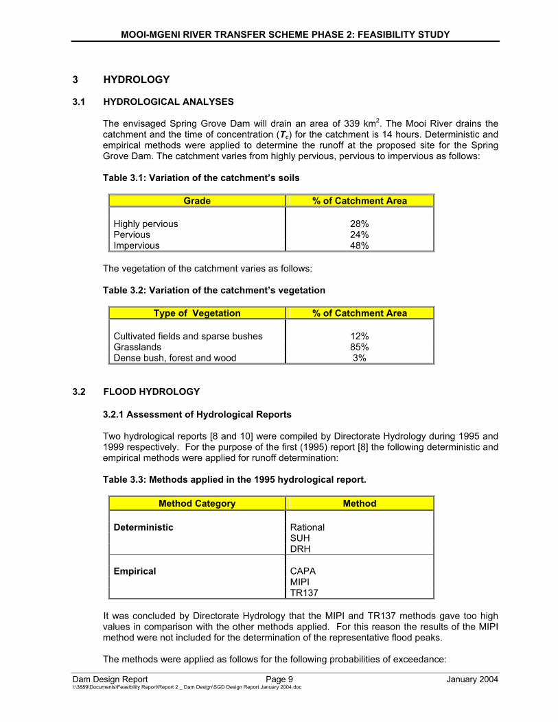
3 HYDROLOGY 3.1 HYDROLOGICAL ANALYSES
The envisaged Spring Grove Dam will drain an area of 339 km2. The Mooi River drains the catchment and the time of concentration (Tc) for the catchment is 14 hours. Deterministic and empirical methods were applied to determine the runoff at the proposed site for the Spring Grove Dam. The catchment varies from highly pervious, pervious to impervious as follows: Table 3.1: Variation of the catchment’s soils
Grade % of Catchment Area Highly pervious 28% Pervious 24% Impervious 48%
The vegetation of the catchment varies as follows: Table 3.2: Variation of the catchment’s vegetation
Type of Vegetation % of Catchment Area Cultivated fields and sparse bushes 12% Grasslands 85% Dense bush, forest and wood 3%
3.2 FLOOD HYDROLOGY
3.2.1 Assessment of Hydrological Reports Two hydrological reports [8 and 10] were compiled by Directorate Hydrology during 1995 and 1999 respectively. For the purpose of the first (1995) report [8] the following deterministic and empirical methods were applied for runoff determination: Table 3.3: Methods applied in the 1995 hydrological report.
Method Category Method
Deterministic Rational SUH DRH Empirical CAPA MIPI TR137
It was concluded by Directorate Hydrology that the MIPI and TR137 methods gave too high values in comparison with the other methods applied. For this reason the results of the MIPI method were not included for the determination of the representative flood peaks. The methods were applied as follows for the following probabilities of exceedance:
MOOI-MGENI RIVER TRANSFER SCHEME PHASE 2: FEASIBILITY STUDY
Dam Design Report Page 10 January 2004 I:\3889\Documents\Feasibility Report\Report 2 _ Dam Design\SGD Design Report January 2004.doc
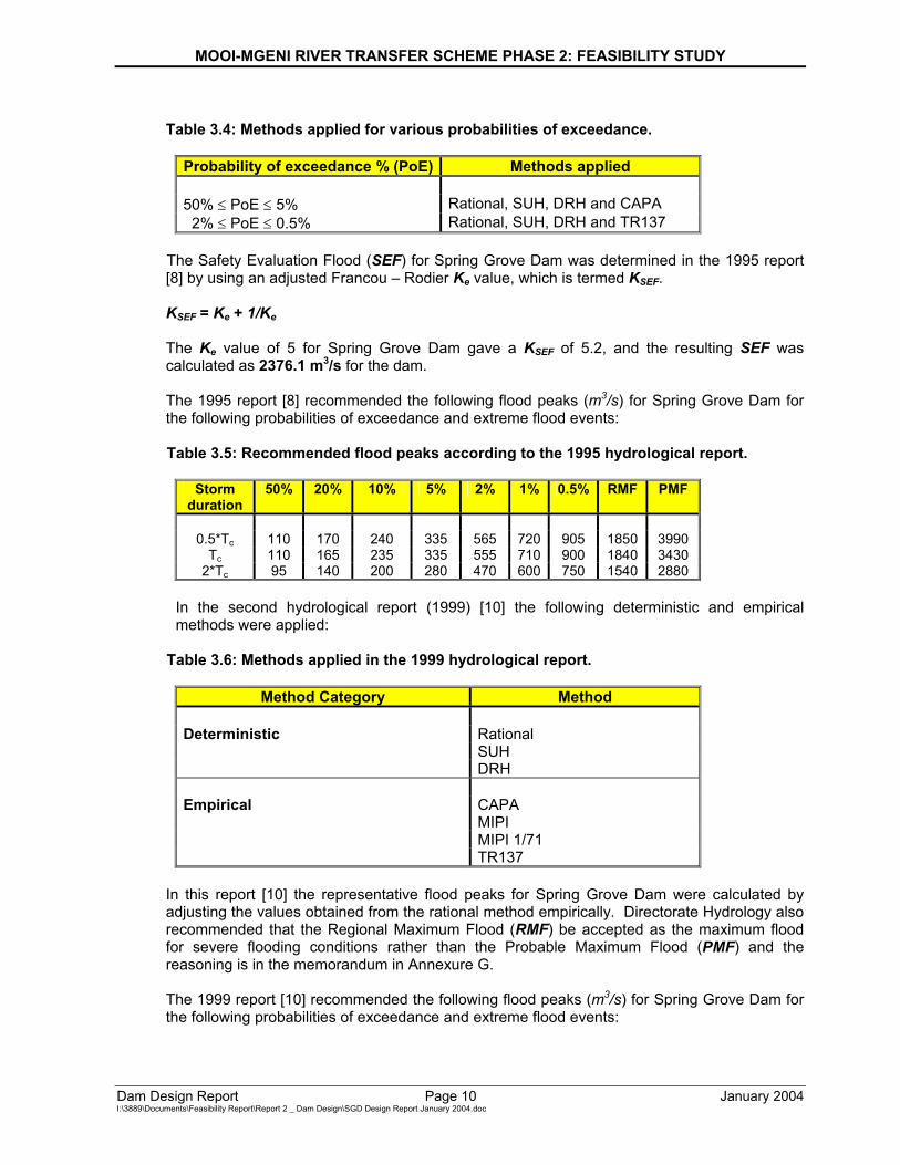
Table 3.4: Methods applied for various probabilities of exceedance.
Probability of exceedance % (PoE) Methods applied 50% ≤ PoE ≤ 5% Rational, SUH, DRH and CAPA 2% ≤ PoE ≤ 0.5% Rational, SUH, DRH and TR137
The Safety Evaluation Flood (SEF) for Spring Grove Dam was determined in the 1995 report [8] by using an adjusted Francou – Rodier Ke value, which is termed KSEF. KSEF = Ke + 1/Ke The Ke value of 5 for Spring Grove Dam gave a KSEF of 5.2, and the resulting SEF was calculated as 2376.1 m3/s for the dam. The 1995 report [8] recommended the following flood peaks (m3/s) for Spring Grove Dam for the following probabilities of exceedance and extreme flood events: Table 3.5: Recommended flood peaks according to the 1995 hydrological report.
Storm
duration 50% 20% 10% 5% 2% 1% 0.5% RMF PMF
0.5*Tc 110 170 240 335 565 720 905 1850 3990
Tc 110 165 235 335 555 710 900 1840 3430 2*Tc 95 140 200 280 470 600 750 1540 2880
In the second hydrological report (1999) [10] the following deterministic and empirical methods were applied:
Table 3.6: Methods applied in the 1999 hydrological report.
Method Category Method
Deterministic Rational SUH DRH Empirical CAPA MIPI MIPI 1/71 TR137
In this report [10] the representative flood peaks for Spring Grove Dam were calculated by adjusting the values obtained from the rational method empirically. Directorate Hydrology also recommended that the Regional Maximum Flood (RMF) be accepted as the maximum flood for severe flooding conditions rather than the Probable Maximum Flood (PMF) and the reasoning is in the memorandum in Annexure G. The 1999 report [10] recommended the following flood peaks (m3/s) for Spring Grove Dam for the following probabilities of exceedance and extreme flood events:
MOOI-MGENI RIVER TRANSFER SCHEME PHASE 2: FEASIBILITY STUDY
Dam Design Report Page 11 January 2004 I:\3889\Documents\Feasibility Report\Report 2 _ Dam Design\SGD Design Report January 2004.doc
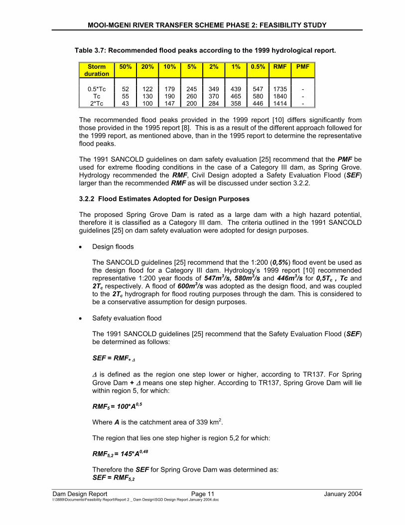
Table 3.7: Recommended flood peaks according to the 1999 hydrological report.
Storm duration
50% 20% 10% 5% 2% 1% 0.5% RMF PMF
0.5*Tc 52 122 179 245 349 439 547 1735 -
Tc 55 130 190 260 370 465 580 1840 - 2*Tc 43 100 147 200 284 358 446 1414 -
The recommended flood peaks provided in the 1999 report [10] differs significantly from those provided in the 1995 report [8]. This is as a result of the different approach followed for the 1999 report, as mentioned above, than in the 1995 report to determine the representative flood peaks. The 1991 SANCOLD guidelines on dam safety evaluation [25] recommend that the PMF be used for extreme flooding conditions in the case of a Category III dam, as Spring Grove. Hydrology recommended the RMF, Civil Design adopted a Safety Evaluation Flood (SEF) larger than the recommended RMF as will be discussed under section 3.2.2. 3.2.2 Flood Estimates Adopted for Design Purposes The proposed Spring Grove Dam is rated as a large dam with a high hazard potential, therefore it is classified as a Category III dam. The criteria outlined in the 1991 SANCOLD guidelines [25] on dam safety evaluation were adopted for design purposes.
• Design floods
The SANCOLD guidelines [25] recommend that the 1:200 (0,5%) flood event be used as the design flood for a Category III dam. Hydrology’s 1999 report [10] recommended representative 1:200 year floods of 547m3/s, 580m3/s and 446m3/s for 0,5Tc , Tc and 2Tc respectively. A flood of 600m3/s was adopted as the design flood, and was coupled to the 2Tc hydrograph for flood routing purposes through the dam. This is considered to be a conservative assumption for design purposes.
• Safety evaluation flood The 1991 SANCOLD guidelines [25] recommend that the Safety Evaluation Flood (SEF) be determined as follows: SEF = RMF+ ∆ ∆ is defined as the region one step lower or higher, according to TR137. For Spring Grove Dam + ∆ means one step higher. According to TR137, Spring Grove Dam will lie within region 5, for which: RMF5 = 100*A0,5 Where A is the catchment area of 339 km2. The region that lies one step higher is region 5,2 for which: RMF5,2 = 145*A0,48 Therefore the SEF for Spring Grove Dam was determined as: SEF = RMF5,2
MOOI-MGENI RIVER TRANSFER SCHEME PHASE 2: FEASIBILITY STUDY
Dam Design Report Page 12 January 2004 I:\3889\Documents\Feasibility Report\Report 2 _ Dam Design\SGD Design Report January 2004.doc
The SEF for Spring Grove Dam was calculated as 2376,10m3/s, but a SEF of 2400m3/s was adopted as the SEF. This SEF was coupled to the 2Tc hydrograph for flood routing purposes through the dam. Once again this is considered to be a conservative assumption for feasibility design purposes.
• Extreme flooding conditions The 1991 SANCOLD guidelines [25] recommend that the Probable Maximum Flood (PMF) also be routed through the dam for a Category III dam. Hydrology’s 1999 report [10] recommend that the Regional Maximum Flood (RMF) be used as the criteria for extreme flooding conditions. This is based on findings (Annexure G) that the Probable Maximum Flood (PMF) is unreliable. More statistical evidence is now available since the methods of determining the Probable Maximum Flood (PMF) were derived. This statistical evidence has proved that the calculated Probable Maximum Flood (PMF) is too high. Civil Design concurs with this opinion.
3.3 GAUGING STATION
A gauging station downstream of the proposed Spring Grove Dam is proposed to gauge future releases from the dam.
MOOI-MGENI RIVER TRANSFER SCHEME PHASE 2: FEASIBILITY STUDY
Dam Design Report Page 13 January 2004 I:\3889\Documents\Feasibility Report\Report 2 _ Dam Design\SGD Design Report January 2004.doc
4 GEOLOGY 4.1 GEOLOGICAL INVESTIGATIONS
The feasibility design of Spring Grove Dam is based on the geological information as provided in the engineering geological report [14], which was compiled during 1999 by the Council for Geoscience. The geological investigation was based on the findings from thirteen holes drilled in the vicinity of the dam’s proposed centreline. From these holes the proposed excavation depths and estimated foundation permeability were determined.
A report compiled by Kijko and Graham [17] during 1999 assesses the seismic hazard parameters for the dam site. This report found that a maximum credible earthquake of magnitude 6,78 ± 0,53 could be considered for a radius of 300 km from the dam site. A deterministic assessment of the median values of the maximum credible horizontal and vertical ground accelerations at the site yields values of 0,32g (313,92 cm.s-2) and 0,19g (186,39 cm.s-2) respectively. This is based on the worst case scenario. A probabilistic assessment of the peak ground acceleration indicated that such an event has one in a million chance of occurrence at the site. For feasibility study design purposes, horizontal ground acceleration of 0,10 g and vertical ground acceleration of 0,06 g for the static stability analyses were accepted. It is recommended that dynamic stability analyses be performed for the ground accelerations as provided by Kijko and Graham [17] during the final design stage.
4.2 DESCRIPTION OF GEOLOGY
4.2.1 Regional The proposed Spring Grove Dam site is located in an area underlain by sedimentary rocks of the Karoo Super Group, which have subsequently been intruded by a dolerite sill. The alternating succession of siltstones and sandstones at this locality are part of the Estcourt formation of the Beaufort group. The sedimentary rocks are essentially horizontally bedded although a regional dip of 3 – 7o can be discerned towards the west. The younger intrusive dolerite sill has resulted in locally distributed horizons with contact metamorphism a common feature. No regional-scale faults have been identified near the vicinity of the proposed dam site. No economic deposits occur within the dam basin area. 4.2.2 Local Alternating siltstone and sandstone strata of the Estcourt formation, Beaufort Group and Karoo Super Group underlies the proposed Spring Grove Dam site. Extensive rock outcrop is exposed within the river section with alluvial deposits only occurring at the base of the lower flank slopes. Areas of rock and boulders can be observed on both the left and right flanks at the proposed site. These boulder zones are related to the underlying dolerite lithology. No spring lines were encountered at the proposed dam site.
MOOI-MGENI RIVER TRANSFER SCHEME PHASE 2: FEASIBILITY STUDY
Dam Design Report Page 14 January 2004 I:\3889\Documents\Feasibility Report\Report 2 _ Dam Design\SGD Design Report January 2004.doc
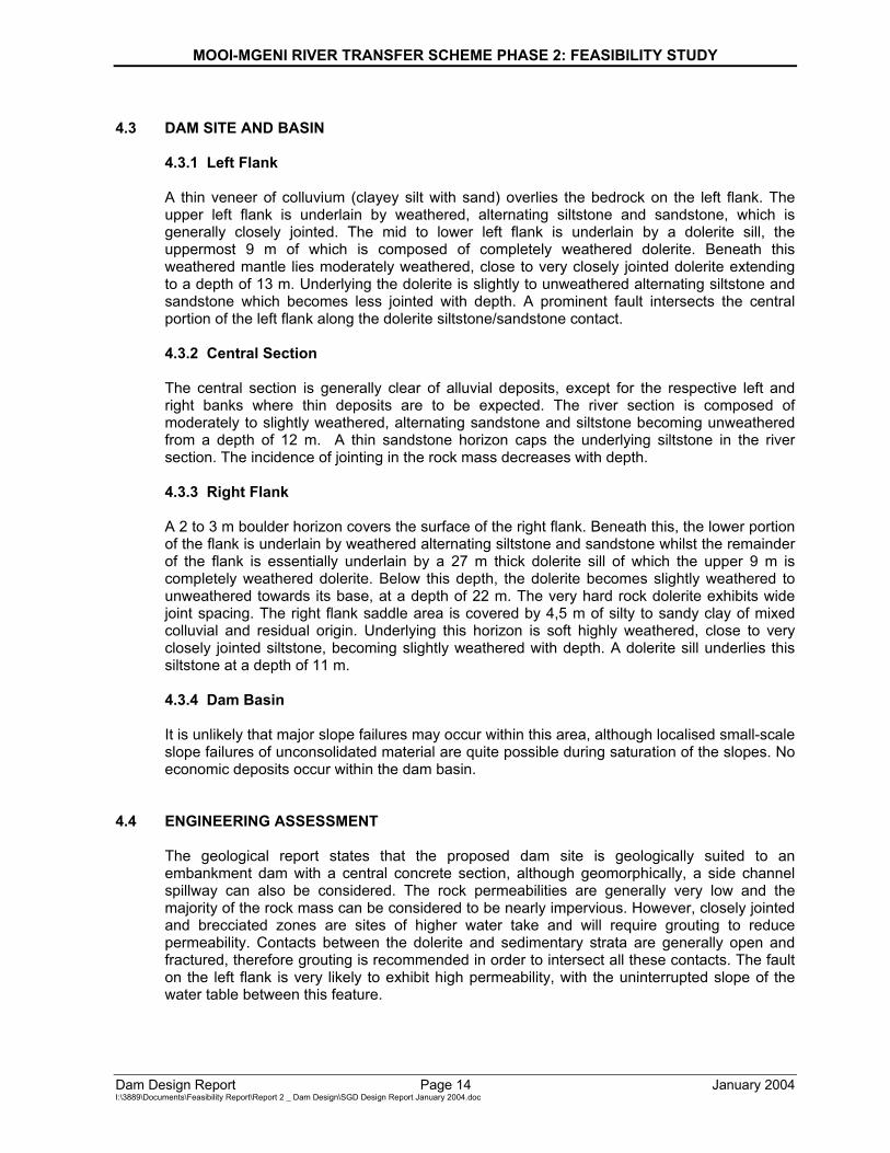
4.3 DAM SITE AND BASIN
4.3.1 Left Flank
A thin veneer of colluvium (clayey silt with sand) overlies the bedrock on the left flank. The upper left flank is underlain by weathered, alternating siltstone and sandstone, which is generally closely jointed. The mid to lower left flank is underlain by a dolerite sill, the uppermost 9 m of which is composed of completely weathered dolerite. Beneath this weathered mantle lies moderately weathered, close to very closely jointed dolerite extending to a depth of 13 m. Underlying the dolerite is slightly to unweathered alternating siltstone and sandstone which becomes less jointed with depth. A prominent fault intersects the central portion of the left flank along the dolerite siltstone/sandstone contact.
4.3.2 Central Section
The central section is generally clear of alluvial deposits, except for the respective left and right banks where thin deposits are to be expected. The river section is composed of moderately to slightly weathered, alternating sandstone and siltstone becoming unweathered from a depth of 12 m. A thin sandstone horizon caps the underlying siltstone in the river section. The incidence of jointing in the rock mass decreases with depth.
4.3.3 Right Flank
A 2 to 3 m boulder horizon covers the surface of the right flank. Beneath this, the lower portion of the flank is underlain by weathered alternating siltstone and sandstone whilst the remainder of the flank is essentially underlain by a 27 m thick dolerite sill of which the upper 9 m is completely weathered dolerite. Below this depth, the dolerite becomes slightly weathered to unweathered towards its base, at a depth of 22 m. The very hard rock dolerite exhibits wide joint spacing. The right flank saddle area is covered by 4,5 m of silty to sandy clay of mixed colluvial and residual origin. Underlying this horizon is soft highly weathered, close to very closely jointed siltstone, becoming slightly weathered with depth. A dolerite sill underlies this siltstone at a depth of 11 m.
4.3.4 Dam Basin
It is unlikely that major slope failures may occur within this area, although localised small-scale slope failures of unconsolidated material are quite possible during saturation of the slopes. No economic deposits occur within the dam basin.
4.4 ENGINEERING ASSESSMENT
The geological report states that the proposed dam site is geologically suited to an embankment dam with a central concrete section, although geomorphically, a side channel spillway can also be considered. The rock permeabilities are generally very low and the majority of the rock mass can be considered to be nearly impervious. However, closely jointed and brecciated zones are sites of higher water take and will require grouting to reduce permeability. Contacts between the dolerite and sedimentary strata are generally open and fractured, therefore grouting is recommended in order to intersect all these contacts. The fault on the left flank is very likely to exhibit high permeability, with the uninterrupted slope of the water table between this feature.
MOOI-MGENI RIVER TRANSFER SCHEME PHASE 2: FEASIBILITY STUDY
Dam Design Report Page 15 January 2004 I:\3889\Documents\Feasibility Report\Report 2 _ Dam Design\SGD Design Report January 2004.doc
4.5 PROPOSED EXCAVATION DEPTHS
Excavation depths for an embankment dam range from 5 m on the left flank, to 1 m in the central section, and to 4 m on the right flank. For a concrete structure excavation depths of 13,5 m and 9 m may be assumed for the upper and mid-lower left flank respectively, whilst a depth of 2 m is assumed in the river section. An excavation depth of 9 m for the majority of the right flank is suggested for a concrete structure.
MOOI-MGENI RIVER TRANSFER SCHEME PHASE 2: FEASIBILITY STUDY
Dam Design Report Page 16 January 2004 I:\3889\Documents\Feasibility Report\Report 2 _ Dam Design\SGD Design Report January 2004.doc
5 SPILLWAY 5.1 DESIGN PHILOSOPHY
The spillway is designed with the objective to discharge excess inflow in a controlled manner, safely and effectively without endangering the dam itself or downstream inhabitants.
5.2 DESIGN CRITERIA
Based upon the calculated design flood and the routed SEF outflow (600 and 1705 m3/s), five spillway lengths were evaluated in terms of its: • Ability to handle the design and safety evaluation floods; and • Backwater impact. The objective was to obtain a spillway length, which satisfies the above mentioned criteria and can be retained within the river section.
5.3 SPILLWAY SELECTION
The spillway selection was based upon the design criteria, and the consideration of certain options with respect to efficiency and costs.
The following options were considered:
a) Conventional mass concrete spillway with the length of spillway ranging from 60 to 120
metres, and
b) A central trough spillway.
A conventional 60 metre long rollcrete gravity spillway was selected, since it:
• Satisfied the design criteria; • Can be retained within the river section; and • Is more economical than the central trough option.
This spillway’s backwater impact was compared with the backwater impacts of longer spillways. The additional backwater impact of this layout was found to be negligible compared to the impact of the longer spillways.
5.4 PROPOSED LAYOUT
5.4.1 Rating Curve
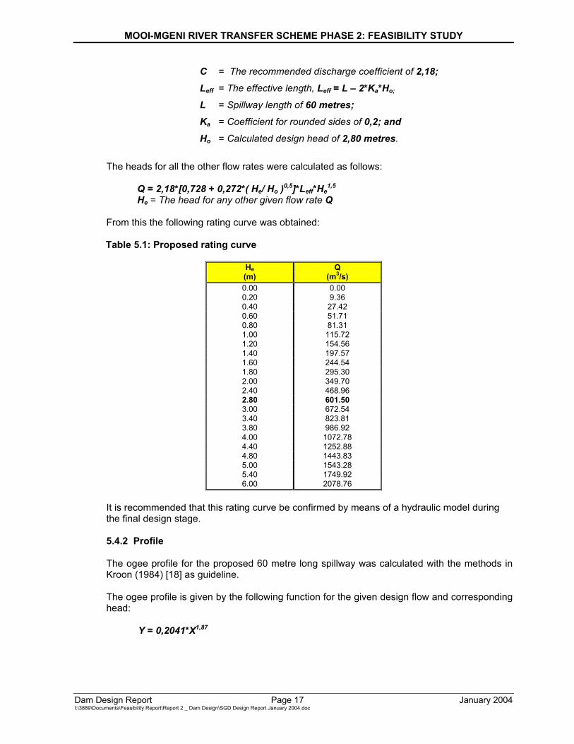
The rating curve was calculated with the methods in Kroon (1984) [18] as guideline. The design head was calculated as follows:
Qo = C*Leff*Ho1,5
Where: Qo = The design flood of 600 m3/s;
MOOI-MGENI RIVER TRANSFER SCHEME PHASE 2: FEASIBILITY STUDY
Dam Design Report Page 17 January 2004 I:\3889\Documents\Feasibility Report\Report 2 _ Dam Design\SGD Design Report January 2004.doc
C = The recommended discharge coefficient of 2,18; Leff = The effective length, Leff = L – 2*Ka*Ho; L = Spillway length of 60 metres; Ka = Coefficient for rounded sides of 0,2; and Ho = Calculated design head of 2,80 metres.
The heads for all the other flow rates were calculated as follows:
Q = 2,18*[0,728 + 0,272*( He/ Ho )0,5]*Leff*He1,5
He = The head for any other given flow rate Q From this the following rating curve was obtained: Table 5.1: Proposed rating curve
He Q (m) (m3/s) 0.00 0.00 0.20 9.36 0.40 27.42 0.60 51.71 0.80 81.31 1.00 115.72 1.20 154.56 1.40 197.57 1.60 244.54 1.80 295.30 2.00 349.70 2.40 468.96 2.80 601.50 3.00 672.54 3.40 823.81 3.80 986.92 4.00 1072.78 4.40 1252.88 4.80 1443.83 5.00 1543.28 5.40 1749.92 6.00 2078.76
It is recommended that this rating curve be confirmed by means of a hydraulic model during the final design stage.
5.4.2 Profile
The ogee profile for the proposed 60 metre long spillway was calculated with the methods in Kroon (1984) [18] as guideline. The ogee profile is given by the following function for the given design flow and corresponding head:
Y = 0,2041*X1,87
MOOI-MGENI RIVER TRANSFER SCHEME PHASE 2: FEASIBILITY STUDY
Dam Design Report Page 18 January 2004 I:\3889\Documents\Feasibility Report\Report 2 _ Dam Design\SGD Design Report January 2004.doc
Together with the following parameters:
Xc = 0,798 m; Yc = 0,350 m; R1 = 1,470 m; R2 = 0,658 m; and
Point of intersection (for 0,75 H : 1 V downstream slope): X = 4,211 m Y = 3,003 m
5.4.3 Energy Dissipation The proposed means of energy dissipation were determined with the methods in Kroon [18] and Novak [20] as guideline. Since it is envisaged that the spillway will be a rollcrete structure, the energy dissipation over the stepped spillway was also taken into consideration. The results of recent research conducted at the University of the Witwatersrand on stepped spillways, were used as guideline in this regard. The following three options were considered: • The USBR Type 3 Stilling Basin;
• A Hydraulic Jump; and
• A Ski-jump option. The Hydraulic Jump Stilling Basin proved to be a relatively long and deep structure, if 70% energy dissipation is considered over the spillway steps. The Ski-jump option proved to be a relatively large concrete structure. The USBR Type 3 Stilling Basin proved to be the most favourable option, if 70% energy dissipation is considered over the spillway steps. This structure will be 15 metres wide and 1,20 metres deep. It will contain a total of 49 chute blocks and 37 baffle blocks over the entire spillway length of 60 metres. This was designed on the basis of the 600m3/s design flood, and the corresponding tailwater depth of 3,30 metres. The USBR Type 3 Stilling Basin does not compare favourably with the means of energy dissipation at existing rollcrete dams, e.g. Wriggleswade [4] and Zaaihoek, where the energy dissipation is achieved by means of a relatively short Hydraulic Jump Stilling Basin. It was estimated that energy dissipation over the spillway steps for these dams are in the order of 90% instead of 70%. The hydraulic jump downstream of the spillway is submerged if 90% energy dissipation is considered over the spillway steps. If 90%, instead of 70%, energy dissipation is considered over the spillway steps for Spring Grove Dam, it was estimated that a 7 to 10 metres wide Hydraulic Jump Spillway would be sufficient. This stilling basin will then be 1,5 metres deep with a 1 metre wide end sill with a upstream slope of 1H : 2V. This stilling basin compares more favourably with means of energy dissipation at existing rollcrete dams.
It is recommended that the suggested energy dissipation be evaluated and confirmed by means of a hydraulic model study during the final design stage. The first test should involve a Hydraulic Jump Stilling Basin with a total width of 10 metres and a depth of 1,5 metres, together with the end sill.
5.4.4 Training Walls
The dimension of the training walls, for the proposed 60 metre long spillway, were determined with the methods in Kroon [18] as guideline. The flow profile over and along the spillway was
MOOI-MGENI RIVER TRANSFER SCHEME PHASE 2: FEASIBILITY STUDY
Dam Design Report Page 19 January 2004 I:\3889\Documents\Feasibility Report\Report 2 _ Dam Design\SGD Design Report January 2004.doc
determined for the given design flow and corresponding head. The training walls will have a slope of 0,75 H : 1 V, which is the same as for the spillway. The estimated width between the down stream face of the spillway and the training walls is 2 metres, this will allow for a sufficient freeboard (> 1,0 m) for the design flow of 600 m3/s. It is recommended that the suggested dimensions for the training walls be evaluated and confirmed by means of a hydraulic model study during the final design stage.
5.5 DOWNSTREAM EROSION PROTECTION
5.5.1 Tailwater Levels
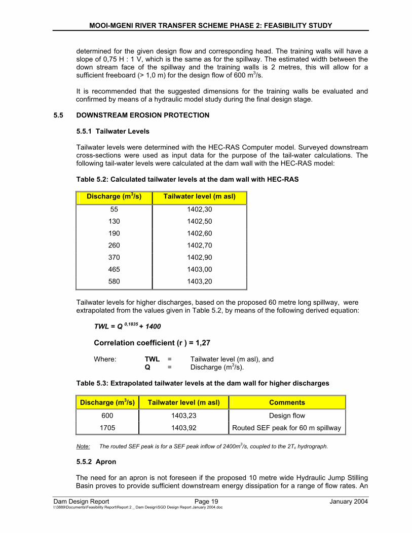
Tailwater levels were determined with the HEC-RAS Computer model. Surveyed downstream cross-sections were used as input data for the purpose of the tail-water calculations. The following tail-water levels were calculated at the dam wall with the HEC-RAS model: Table 5.2: Calculated tailwater levels at the dam wall with HEC-RAS
Discharge (m3/s) Tailwater level (m asl)
55 1402,30
130 1402,50
190 1402,60
260 1402,70
370 1402,90
465 1403,00
580 1403,20
Tailwater levels for higher discharges, based on the proposed 60 metre long spillway, were extrapolated from the values given in Table 5.2, by means of the following derived equation:
TWL = Q 0,1835 + 1400
Correlation coefficient (r ) = 1,27
Where: TWL = Tailwater level (m asl), and Q = Discharge (m3/s). Table 5.3: Extrapolated tailwater levels at the dam wall for higher discharges
Discharge (m3/s) Tailwater level (m asl) Comments
600 1403,23 Design flow
1705 1403,92 Routed SEF peak for 60 m spillway Note: The routed SEF peak is for a SEF peak inflow of 2400m3/s, coupled to the 2Tc hydrograph.
5.5.2 Apron
The need for an apron is not foreseen if the proposed 10 metre wide Hydraulic Jump Stilling Basin proves to provide sufficient downstream energy dissipation for a range of flow rates. An
MOOI-MGENI RIVER TRANSFER SCHEME PHASE 2: FEASIBILITY STUDY
Dam Design Report Page 20 January 2004 I:\3889\Documents\Feasibility Report\Report 2 _ Dam Design\SGD Design Report January 2004.doc
apron will probably be needed downstream of the stilling basin if it is decided to construct a narrower stilling basin. During the final design stage it will be necessary to evaluate whether a wider stilling basin with no apron, or a narrower stilling basin with an apron will be the most desired option. It is recommended that this evaluation be done on the basis of a hydraulic model study, for a wide range of flow rates, during the final design stage.
5.6 FLOOD ROUTING
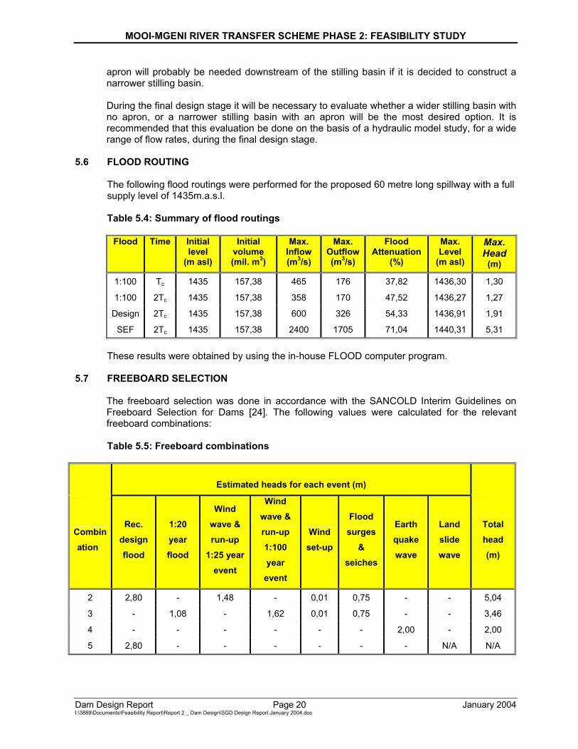
The following flood routings were performed for the proposed 60 metre long spillway with a full supply level of 1435m.a.s.l.
Table 5.4: Summary of flood routings
Flood Time Initial level
(m asl)
Initial volume (mil. m3)
Max. Inflow (m3/s)
Max. Outflow (m3/s)
Flood Attenuation
(%)
Max. Level
(m asl)
Max. Head
(m)
1:100 Tc 1435 157,38 465 176 37,82 1436,30 1,30
1:100 2Tc 1435 157,38 358 170 47,52 1436,27 1,27
Design 2Tc 1435 157,38 600 326 54,33 1436,91 1,91
SEF 2Tc 1435 157,38 2400 1705 71,04 1440,31 5,31
These results were obtained by using the in-house FLOOD computer program.
5.7 FREEBOARD SELECTION
The freeboard selection was done in accordance with the SANCOLD Interim Guidelines on Freeboard Selection for Dams [24]. The following values were calculated for the relevant freeboard combinations: Table 5.5: Freeboard combinations
Estimated heads for each event (m)
Combination
Rec. design flood
1:20 year flood
Wind wave & run-up
1:25 year event
Wind wave & run-up 1:100 year event
Wind set-up
Flood surges
& seiches
Earth quake wave
Land slide wave
Total head (m)
2 2,80 - 1,48 - 0,01 0,75 - - 5,04
3 - 1,08 - 1,62 0,01 0,75 - - 3,46
4 - - - - - - 2,00 - 2,00
5 2,80 - - - - - - N/A N/A
MOOI-MGENI RIVER TRANSFER SCHEME PHASE 2: FEASIBILITY STUDY
Dam Design Report Page 21 January 2004 I:\3889\Documents\Feasibility Report\Report 2 _ Dam Design\SGD Design Report January 2004.doc
The estimated total heads for the suggested freeboard combinations were compared with the head of 5,31 metre for the SEF. It was concluded that a freeboard of 6 metres be selected. It is recommended that combination 5 be investigated during the final design stage in order to ensure that the selected freeboard of 6 metres is in order.
MOOI-MGENI RIVER TRANSFER SCHEME PHASE 2: FEASIBILITY STUDY
Dam Design Report Page 22 January 2004 I:\3889\Documents\Feasibility Report\Report 2 _ Dam Design\SGD Design Report January 2004.doc
6 SELECTION OF FULL SUPPLY LEVEL 6.1 BACKWATER ANALYSIS
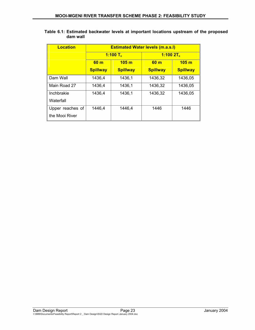
Four backwater analyses were performed by routing the 1:100 year flood Tc and 2Tc hydrographs through the dam basin with an adopted full supply level (FSL) of 1435,0m.a.s.l associated with spillway lengths 60 m and 105 m respectively. The backwater analyses were performed using the MIKE 11 computer model. The analyses for the 1:100 Tc hydrograph yielded the highest backwater levels in the dam. Land expropriation and the relocation of services will be planned and implemented according to the 1:100 year backwater profiles. The estimated water levels for the four above mentioned analyses do not differ substantially from one another. The estimated water levels of the Tc 1:100 year flood, with a 60 m spillway, were plotted on the 1:5000 scale contour plans of the dam basin for feasibility study purposes. Note that the FSL was changed to 1433,5m.a.s.l at a late stage of the feasibility design. These and other calculations have not been redone for the revised FSL.
6.2 IMPACT ON INFRASTRUCTURE AND ENVIRONMENT
6.2.1 Main Road 27
The proposed Spring Grove Dam will have an impact on Main Road 27, which links Nottingham Road and Himeville/Sani Pass. The road crosses a tributary of the Mooi River upstream of the proposed dam site by means of one 3,0 x 3,0 m box culvert. This culvert will already be inundated when the full supply level of the dam exceeds 1434,50m.a.s.l. 1:100 year flood event a backwater level of 1436,100m.a.s.l can be expected at Main Road 27. The road surface level above the culvert is at 1439,623m.a.s.l. Only a full supply level of less than 1432,00m.a.s.l.will have no significant impact on the culvert, but this will result in the proposed dam being to small. It was concluded that the road will have to be relocated or strengthened should the full supply level of the proposed dam exceed 1432,00m.a.s.l.
6.2.2 Inchbrakie Waterfalls
These waterfalls are located in the Mooi River upstream of the proposed dam site. According to the topographical data a full supply level of 1435,000m.a.s.l. will already inundate the Inchbrakie Waterfalls. It was concluded that the full supply level of the dam would have to be significantly lowered if the impact thereof is to be minimised on these water falls, which in turn can result in the proposed dam being uneconomical. The impact of the proposed dam on the Inchbrakie Waterfalls will be an issue for serious debate between the DWAF and stakeholders.
6.3 ADOPTED FULL SUPPLY LEVEL
A full supply level of 1435,00m.a.s.l was adopted for feasibility design purposes, this might change though due to the influences of the proposed dam on Main Road 27 and the Inchbrakie Water Falls. The final selected layout of the dam might also influence the final adopted full supply level. Note again that the FSL was changed to 1433,50m.a.s.l at a late stage of the feasibility design. These and other calculations have not been redone for the revised FSL.
MOOI-MGENI RIVER TRANSFER SCHEME PHASE 2: FEASIBILITY STUDY
Dam Design Report Page 23 January 2004 I:\3889\Documents\Feasibility Report\Report 2 _ Dam Design\SGD Design Report January 2004.doc
Table 6.1: Estimated backwater levels at important locations upstream of the proposed dam wall
Location Estimated Water levels (m.a.s.l)
1:100 Tc 1:100 2Tc 60 m
Spillway 105 m
Spillway 60 m
Spillway 105 m
Spillway
Dam Wall 1436,4 1436,1 1436,32 1436,05
Main Road 27 1436,4 1436,1 1436,32 1436,05
Inchbrakie
Waterfall
1436,4 1436,1 1436,32 1436,05
Upper reaches of
the Mooi River
1446,4 1446,4 1446 1446
MOOI-MGENI RIVER TRANSFER SCHEME PHASE 2: FEASIBILITY STUDY
Dam Design Report Page 24 January 2004 I:\3889\Documents\Feasibility Report\Report 2 _ Dam Design\SGD Design Report January 2004.doc
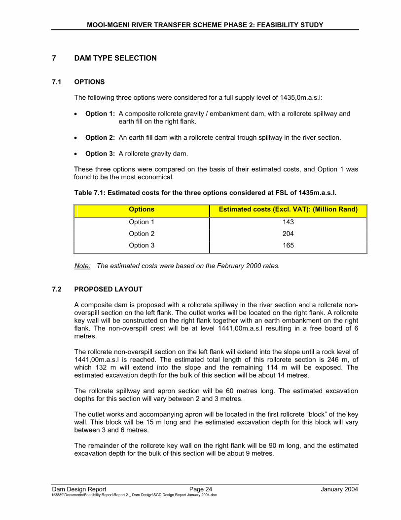
7 DAM TYPE SELECTION 7.1 OPTIONS
The following three options were considered for a full supply level of 1435,0m.a.s.l: • Option 1: A composite rollcrete gravity / embankment dam, with a rollcrete spillway and
earth fill on the right flank.
• Option 2: An earth fill dam with a rollcrete central trough spillway in the river section.
• Option 3: A rollcrete gravity dam. These three options were compared on the basis of their estimated costs, and Option 1 was found to be the most economical. Table 7.1: Estimated costs for the three options considered at FSL of 1435m.a.s.l.
Options Estimated costs (Excl. VAT): (Million Rand)
Option 1 143
Option 2 204
Option 3 165
Note: The estimated costs were based on the February 2000 rates. 7.2 PROPOSED LAYOUT
A composite dam is proposed with a rollcrete spillway in the river section and a rollcrete non-overspill section on the left flank. The outlet works will be located on the right flank. A rollcrete key wall will be constructed on the right flank together with an earth embankment on the right flank. The non-overspill crest will be at level 1441,00m.a.s.l resulting in a free board of 6 metres. The rollcrete non-overspill section on the left flank will extend into the slope until a rock level of 1441,00m.a.s.l is reached. The estimated total length of this rollcrete section is 246 m, of which 132 m will extend into the slope and the remaining 114 m will be exposed. The estimated excavation depth for the bulk of this section will be about 14 metres. The rollcrete spillway and apron section will be 60 metres long. The estimated excavation depths for this section will vary between 2 and 3 metres. The outlet works and accompanying apron will be located in the first rollcrete “block” of the key wall. This block will be 15 m long and the estimated excavation depth for this block will vary between 3 and 6 metres. The remainder of the rollcrete key wall on the right flank will be 90 m long, and the estimated excavation depth for the bulk of this section will be about 9 metres.
MOOI-MGENI RIVER TRANSFER SCHEME PHASE 2: FEASIBILITY STUDY
Dam Design Report Page 25 January 2004 I:\3889\Documents\Feasibility Report\Report 2 _ Dam Design\SGD Design Report January 2004.doc
The earth embankment will be situated on the right flank. The estimated length of the embankment is 295 m from the endpoint of the key wall. The estimated excavation depth for the core trench is in the order of 5 m.
MOOI-MGENI RIVER TRANSFER SCHEME PHASE 2: FEASIBILITY STUDY
Dam Design Report Page 26 January 2004 I:\3889\Documents\Feasibility Report\Report 2 _ Dam Design\SGD Design Report January 2004.doc
8 STABILITY ANALYSIS OF CONCRETE SECTIONS 8.1 LOADS
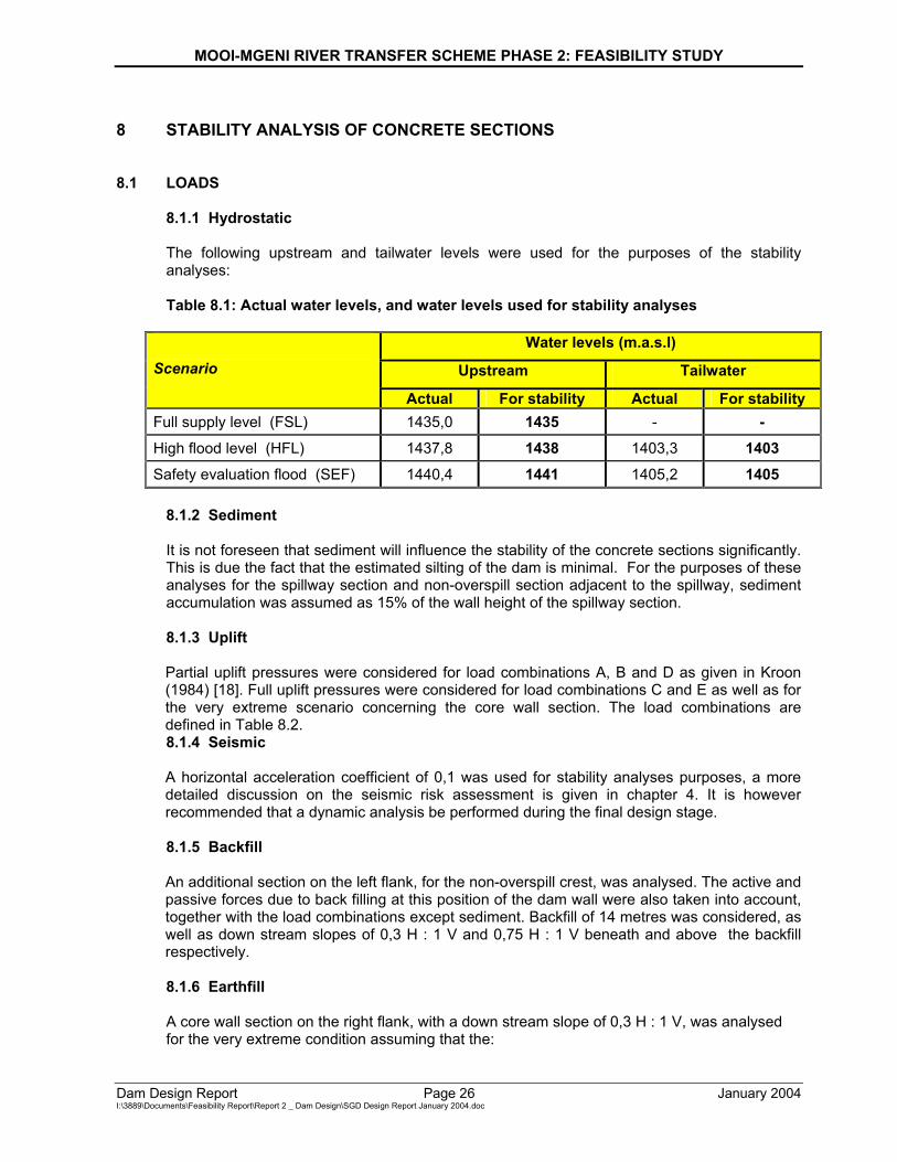
8.1.1 Hydrostatic
The following upstream and tailwater levels were used for the purposes of the stability analyses:
Table 8.1: Actual water levels, and water levels used for stability analyses
Water levels (m.a.s.l)
Upstream Tailwater
Scenario
Actual For stability Actual For stability Full supply level (FSL) 1435,0 1435 - - High flood level (HFL) 1437,8 1438 1403,3 1403 Safety evaluation flood (SEF) 1440,4 1441 1405,2 1405
8.1.2 Sediment
It is not foreseen that sediment will influence the stability of the concrete sections significantly. This is due the fact that the estimated silting of the dam is minimal. For the purposes of these analyses for the spillway section and non-overspill section adjacent to the spillway, sediment accumulation was assumed as 15% of the wall height of the spillway section.
8.1.3 Uplift
Partial uplift pressures were considered for load combinations A, B and D as given in Kroon (1984) [18]. Full uplift pressures were considered for load combinations C and E as well as for the very extreme scenario concerning the core wall section. The load combinations are defined in Table 8.2. 8.1.4 Seismic
A horizontal acceleration coefficient of 0,1 was used for stability analyses purposes, a more detailed discussion on the seismic risk assessment is given in chapter 4. It is however recommended that a dynamic analysis be performed during the final design stage.
8.1.5 Backfill
An additional section on the left flank, for the non-overspill crest, was analysed. The active and passive forces due to back filling at this position of the dam wall were also taken into account, together with the load combinations except sediment. Backfill of 14 metres was considered, as well as down stream slopes of 0,3 H : 1 V and 0,75 H : 1 V beneath and above the backfill respectively. 8.1.6 Earthfill
A core wall section on the right flank, with a down stream slope of 0,3 H : 1 V, was analysed for the very extreme condition assuming that the:
MOOI-MGENI RIVER TRANSFER SCHEME PHASE 2: FEASIBILITY STUDY
Dam Design Report Page 27 January 2004 I:\3889\Documents\Feasibility Report\Report 2 _ Dam Design\SGD Design Report January 2004.doc
• Dam is empty;
• Upstream earthfill is saturated; and
• Downstream earthfill has been washed away.
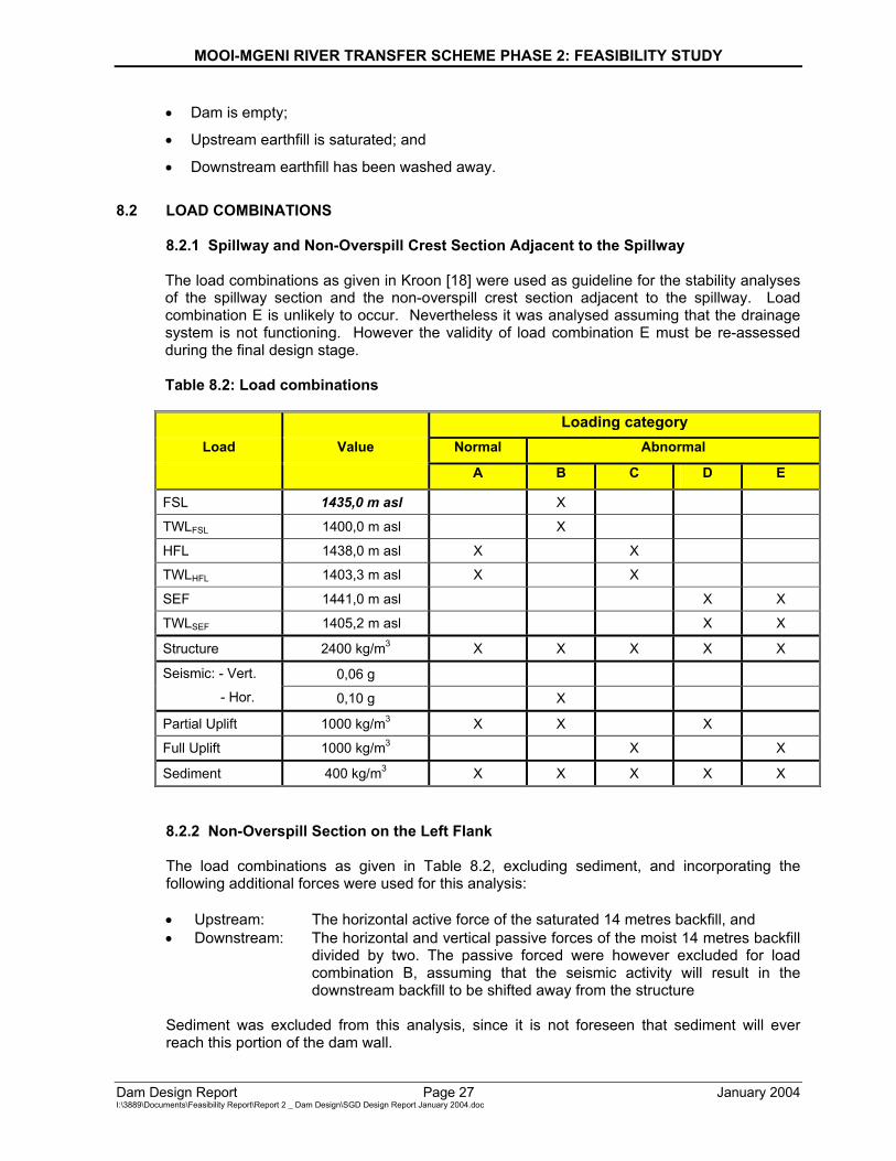
8.2 LOAD COMBINATIONS
8.2.1 Spillway and Non-Overspill Crest Section Adjacent to the Spillway
The load combinations as given in Kroon [18] were used as guideline for the stability analyses of the spillway section and the non-overspill crest section adjacent to the spillway. Load combination E is unlikely to occur. Nevertheless it was analysed assuming that the drainage system is not functioning. However the validity of load combination E must be re-assessed during the final design stage.
Table 8.2: Load combinations
Loading category
Load Value Normal Abnormal
A B C D E
FSL 1435,0 m asl X
TWLFSL 1400,0 m asl X
HFL 1438,0 m asl X X
TWLHFL 1403,3 m asl X X
SEF 1441,0 m asl X X
TWLSEF 1405,2 m asl X X
Structure 2400 kg/m3 X X X X X
0,06 g Seismic: - Vert.
- Hor. 0,10 g X
Partial Uplift 1000 kg/m3 X X X
Full Uplift 1000 kg/m3 X X
Sediment 400 kg/m3 X X X X X
8.2.2 Non-Overspill Section on the Left Flank
The load combinations as given in Table 8.2, excluding sediment, and incorporating the following additional forces were used for this analysis: • Upstream: The horizontal active force of the saturated 14 metres backfill, and • Downstream: The horizontal and vertical passive forces of the moist 14 metres backfill
divided by two. The passive forced were however excluded for load combination B, assuming that the seismic activity will result in the downstream backfill to be shifted away from the structure
Sediment was excluded from this analysis, since it is not foreseen that sediment will ever reach this portion of the dam wall.
MOOI-MGENI RIVER TRANSFER SCHEME PHASE 2: FEASIBILITY STUDY
Dam Design Report Page 28 January 2004 I:\3889\Documents\Feasibility Report\Report 2 _ Dam Design\SGD Design Report January 2004.doc
8.2.3 Core Wall Section on the Right Flank
The following very extreme load combination were used for the purpose of this analyses:
• The weight of the mass concrete structure; • The upstream horizontal active forces of the saturated earth (γsat = 21,5 kN/m3 and
γsub = 11,5 kN/m3 ) and saturated backfill (γsat = 20,2 kN/m3 and γsub = 10,2 kN/m3 ); • The full uplift pressure; and • The downstream horizontal passive force of the saturated backfill.
No downstream passive forces for the earthfill were considered, since it was assumed to have been washed away.
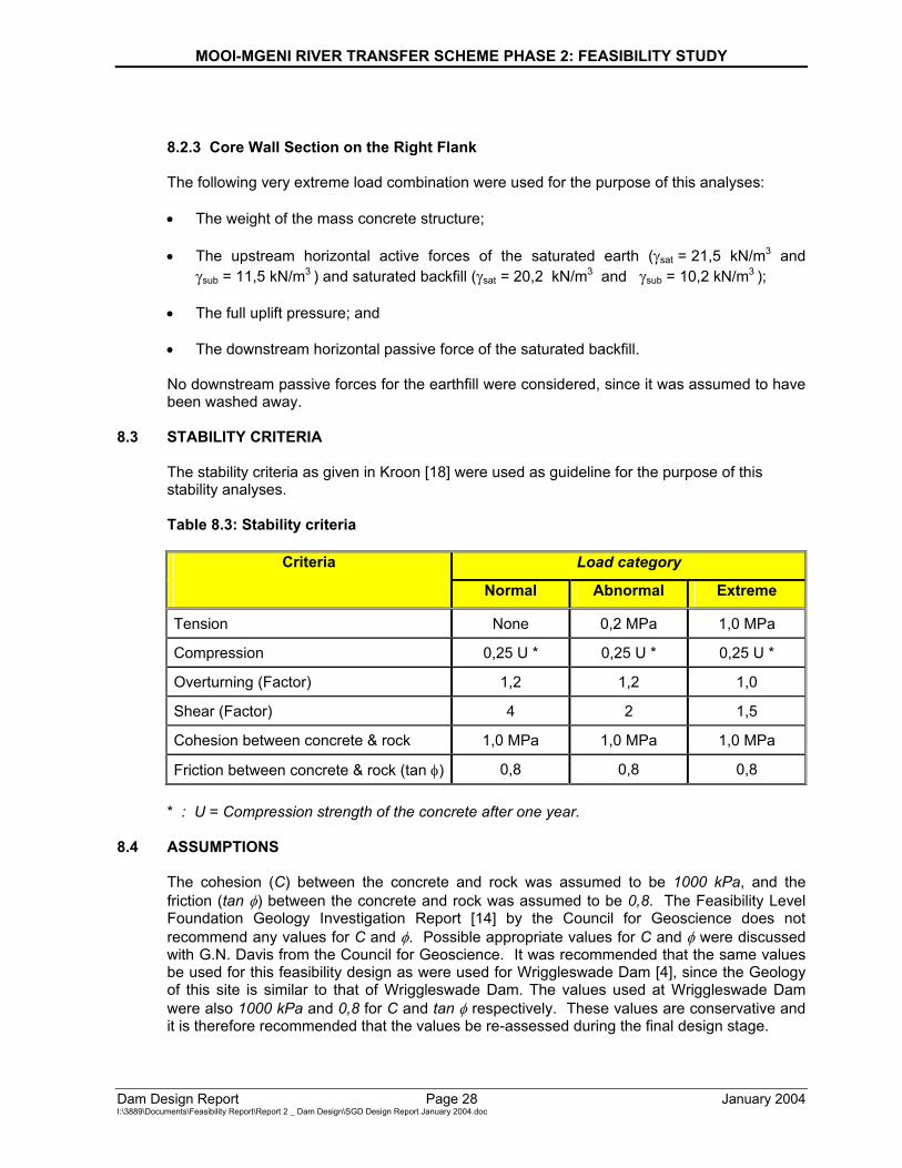
8.3 STABILITY CRITERIA
The stability criteria as given in Kroon [18] were used as guideline for the purpose of this stability analyses. Table 8.3: Stability criteria
Criteria Load category
Normal Abnormal Extreme
Tension None 0,2 MPa 1,0 MPa
Compression 0,25 U * 0,25 U * 0,25 U *
Overturning (Factor) 1,2 1,2 1,0
Shear (Factor) 4 2 1,5
Cohesion between concrete & rock 1,0 MPa 1,0 MPa 1,0 MPa
Friction between concrete & rock (tan φ) 0,8 0,8 0,8 * : U = Compression strength of the concrete after one year.
8.4 ASSUMPTIONS
The cohesion (C) between the concrete and rock was assumed to be 1000 kPa, and the friction (tan φ) between the concrete and rock was assumed to be 0,8. The Feasibility Level Foundation Geology Investigation Report [14] by the Council for Geoscience does not recommend any values for C and φ. Possible appropriate values for C and φ were discussed with G.N. Davis from the Council for Geoscience. It was recommended that the same values be used for this feasibility design as were used for Wriggleswade Dam [4], since the Geology of this site is similar to that of Wriggleswade Dam. The values used at Wriggleswade Dam were also 1000 kPa and 0,8 for C and tan φ respectively. These values are conservative and it is therefore recommended that the values be re-assessed during the final design stage.
MOOI-MGENI RIVER TRANSFER SCHEME PHASE 2: FEASIBILITY STUDY
Dam Design Report Page 29 January 2004 I:\3889\Documents\Feasibility Report\Report 2 _ Dam Design\SGD Design Report January 2004.doc
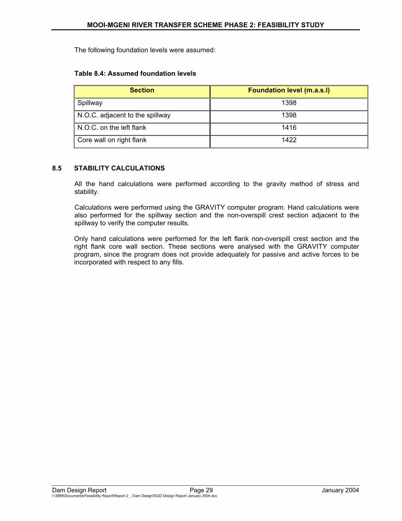
The following foundation levels were assumed: Table 8.4: Assumed foundation levels
Section Foundation level (m.a.s.l)
Spillway 1398
N.O.C. adjacent to the spillway 1398
N.O.C. on the left flank 1416
Core wall on right flank 1422
8.5 STABILITY CALCULATIONS
All the hand calculations were performed according to the gravity method of stress and stability. Calculations were performed using the GRAVITY computer program. Hand calculations were also performed for the spillway section and the non-overspill crest section adjacent to the spillway to verify the computer results. Only hand calculations were performed for the left flank non-overspill crest section and the right flank core wall section. These sections were analysed with the GRAVITY computer program, since the program does not provide adequately for passive and active forces to be incorporated with respect to any fills.
MOOI-MGENI RIVER TRANSFER SCHEME PHASE 2: FEASIBILITY STUDY
Dam Design Report Page 30 January 2004 I:\3889\Documents\Feasibility Report\Report 2 _ Dam Design\SGD Design Report January 2004.doc
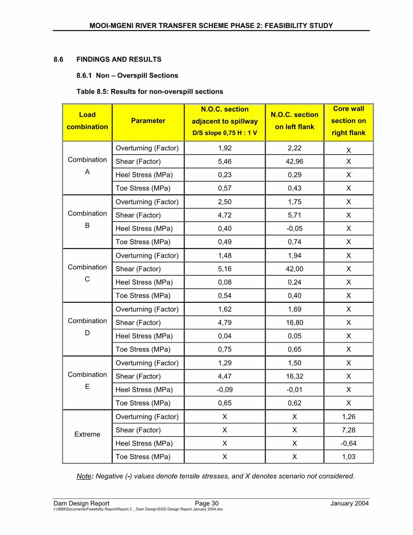
8.6 FINDINGS AND RESULTS
8.6.1 Non – Overspill Sections
Table 8.5: Results for non-overspill sections
Load combination
Parameter N.O.C. section
adjacent to spillway D/S slope 0,75 H : 1 V
N.O.C. section on left flank
Core wall section on right flank
Overturning (Factor) 1,92 2,22 X Shear (Factor) 5,46 42,96 X
Heel Stress (MPa) 0,23 0,29 X
Combination
A
Toe Stress (MPa) 0,57 0,43 X
Overturning (Factor) 2,50 1,75 X
Shear (Factor) 4,72 5,71 X
Heel Stress (MPa) 0,40 -0,05 X
Combination
B
Toe Stress (MPa) 0,49 0,74 X
Overturning (Factor) 1,48 1,94 X
Shear (Factor) 5,16 42,00 X
Heel Stress (MPa) 0,08 0,24 X
Combination
C
Toe Stress (MPa) 0,54 0,40 X
Overturning (Factor) 1,62 1,69 X
Shear (Factor) 4,79 16,80 X
Heel Stress (MPa) 0,04 0,05 X
Combination
D
Toe Stress (MPa) 0,75 0,65 X
Overturning (Factor) 1,29 1,50 X
Shear (Factor) 4,47 16,32 X
Heel Stress (MPa) -0,09 -0,01 X
Combination
E
Toe Stress (MPa) 0,65 0,62 X
Overturning (Factor) X X 1,26
Shear (Factor) X X 7,28
Heel Stress (MPa) X X -0,64 Extreme
Toe Stress (MPa) X X 1,03 Note: Negative (-) values denote tensile stresses, and X denotes scenario not considered.
MOOI-MGENI RIVER TRANSFER SCHEME PHASE 2: FEASIBILITY STUDY
Dam Design Report Page 31 January 2004 I:\3889\Documents\Feasibility Report\Report 2 _ Dam Design\SGD Design Report January 2004.doc
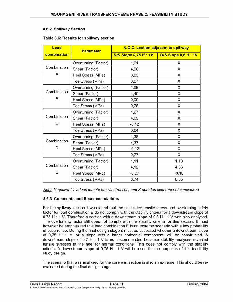
8.6.2 Spillway Section
Table 8.6: Results for spillway section
N.O.C. section adjacent to spillway Load combination
Parameter D/S Slope 0,75 H : 1V D/S Slope 0,8 H : 1V
Overturning (Factor) 1,61 X Shear (Factor) 4,96 X Heel Stress (MPa) 0,03 X
Combination
A
Toe Stress (MPa) 0,67 X Overturning (Factor) 1,69 X Shear (Factor) 4,40 X Heel Stress (MPa) 0,00 X
Combination
B
Toe Stress (MPa) 0,78 X Overturning (Factor) 1,27 X Shear (Factor) 4,69 X Heel Stress (MPa) -0,12 X
Combination
C
Toe Stress (MPa) 0,64 X Overturning (Factor) 1,38 X Shear (Factor) 4,37 X Heel Stress (MPa) -0,12 X
Combination
D
Toe Stress (MPa) 0,77 X Overturning (Factor) 1,11 1,18 Shear (Factor) 4,12 4,36 Heel Stress (MPa) -0,27 -0,18
Combination
E
Toe Stress (MPa) 0,74 0,65
Note: Negative (-) values denote tensile stresses, and X denotes scenario not considered.
8.6.3 Comments and Recommendations For the spillway section it was found that the calculated tensile stress and overturning safety factor for load combination E do not comply with the stability criteria for a downstream slope of 0,75 H : 1 V. Therefore a section with a downstream slope of 0,8 H : 1 V was also analysed. The overturning factor still does not comply with the stability criteria for this section. It must however be emphasised that load combination E is an extreme scenario with a low probability of occurrence. During the final design stage it must be assessed whether a downstream slope of 0,75 H: 1 V, or a slope with a larger horizontal component, will be constructed. A downstream slope of 0,7 H : 1 V is not recommended because stability analyses revealed tensile stresses at the heel for normal conditions. This does not comply with the stability criteria. A downstream slope of 0,75 H : 1 V will be used for the purposes of this feasibility study design. The scenario that was analysed for the core wall section is also an extreme. This should be re-evaluated during the final design stage.
MOOI-MGENI RIVER TRANSFER SCHEME PHASE 2: FEASIBILITY STUDY
Dam Design Report Page 32 January 2004 I:\3889\Documents\Feasibility Report\Report 2 _ Dam Design\SGD Design Report January 2004.doc
9 STABILITY ANALYSIS OF EARTH EMBANKMENT SECTIONS AND SETTLEMENT 9.1 EMBANKMENT DETAILS
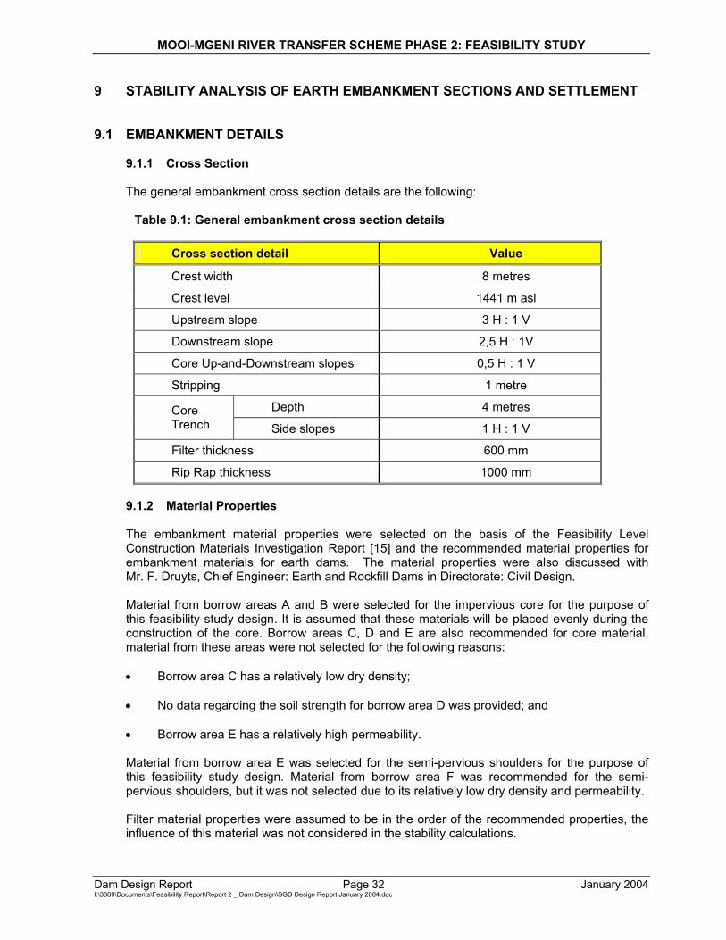
9.1.1 Cross Section
The general embankment cross section details are the following:
Table 9.1: General embankment cross section details
Cross section detail Value
Crest width 8 metres
Crest level 1441 m asl
Upstream slope 3 H : 1 V
Downstream slope 2,5 H : 1V
Core Up-and-Downstream slopes 0,5 H : 1 V
Stripping 1 metre
Depth 4 metres Core Trench Side slopes 1 H : 1 V
Filter thickness 600 mm
Rip Rap thickness 1000 mm 9.1.2 Material Properties The embankment material properties were selected on the basis of the Feasibility Level Construction Materials Investigation Report [15] and the recommended material properties for embankment materials for earth dams. The material properties were also discussed with Mr. F. Druyts, Chief Engineer: Earth and Rockfill Dams in Directorate: Civil Design. Material from borrow areas A and B were selected for the impervious core for the purpose of this feasibility study design. It is assumed that these materials will be placed evenly during the construction of the core. Borrow areas C, D and E are also recommended for core material, material from these areas were not selected for the following reasons: • Borrow area C has a relatively low dry density; • No data regarding the soil strength for borrow area D was provided; and • Borrow area E has a relatively high permeability. Material from borrow area E was selected for the semi-pervious shoulders for the purpose of this feasibility study design. Material from borrow area F was recommended for the semi-pervious shoulders, but it was not selected due to its relatively low dry density and permeability. Filter material properties were assumed to be in the order of the recommended properties, the influence of this material was not considered in the stability calculations.
MOOI-MGENI RIVER TRANSFER SCHEME PHASE 2: FEASIBILITY STUDY
Dam Design Report Page 33 January 2004 I:\3889\Documents\Feasibility Report\Report 2 _ Dam Design\SGD Design Report January 2004.doc
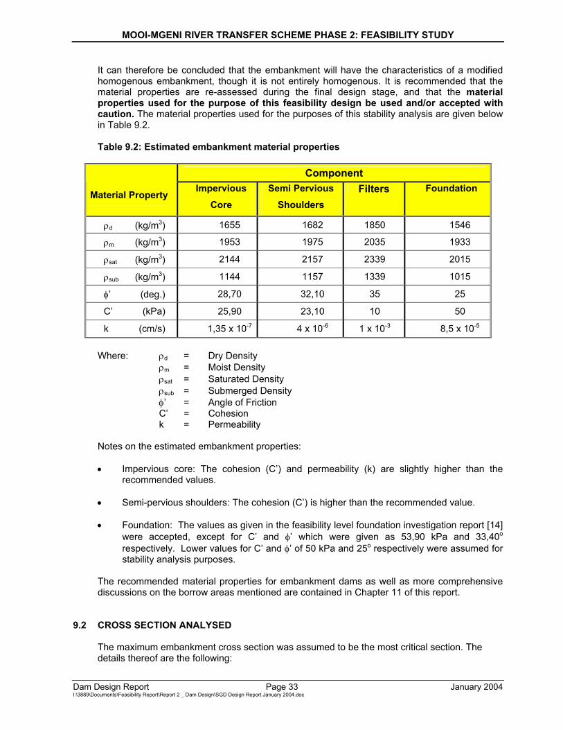
It can therefore be concluded that the embankment will have the characteristics of a modified homogenous embankment, though it is not entirely homogenous. It is recommended that the material properties are re-assessed during the final design stage, and that the material properties used for the purpose of this feasibility design be used and/or accepted with caution. The material properties used for the purposes of this stability analysis are given below in Table 9.2. Table 9.2: Estimated embankment material properties
Component Material Property Impervious
Core Semi Pervious
Shoulders Filters Foundation
ρd (kg/m3) 1655 1682 1850 1546
ρm (kg/m3) 1953 1975 2035 1933
ρsat (kg/m3) 2144 2157 2339 2015
ρsub (kg/m3) 1144 1157 1339 1015
φ’ (deg.) 28,70 32,10 35 25
C’ (kPa) 25,90 23,10 10 50
k (cm/s) 1,35 x 10⁻⁷ 4 x 10⁻⁶ 1 x 10⁻³ 8,5 x 10⁻⁵
Where: ρd = Dry Density ρm = Moist Density ρsat = Saturated Density ρsub = Submerged Density φ’ = Angle of Friction C’ = Cohesion k = Permeability Notes on the estimated embankment properties: • Impervious core: The cohesion (C’) and permeability (k) are slightly higher than the
recommended values. • Semi-pervious shoulders: The cohesion (C’) is higher than the recommended value. • Foundation: The values as given in the feasibility level foundation investigation report [14]
were accepted, except for C’ and φ’ which were given as 53,90 kPa and 33,40o respectively. Lower values for C’ and φ’ of 50 kPa and 25o respectively were assumed for stability analysis purposes.
The recommended material properties for embankment dams as well as more comprehensive discussions on the borrow areas mentioned are contained in Chapter 11 of this report.
9.2 CROSS SECTION ANALYSED The maximum embankment cross section was assumed to be the most critical section. The details thereof are the following:
MOOI-MGENI RIVER TRANSFER SCHEME PHASE 2: FEASIBILITY STUDY
Dam Design Report Page 34 January 2004 I:\3889\Documents\Feasibility Report\Report 2 _ Dam Design\SGD Design Report January 2004.doc
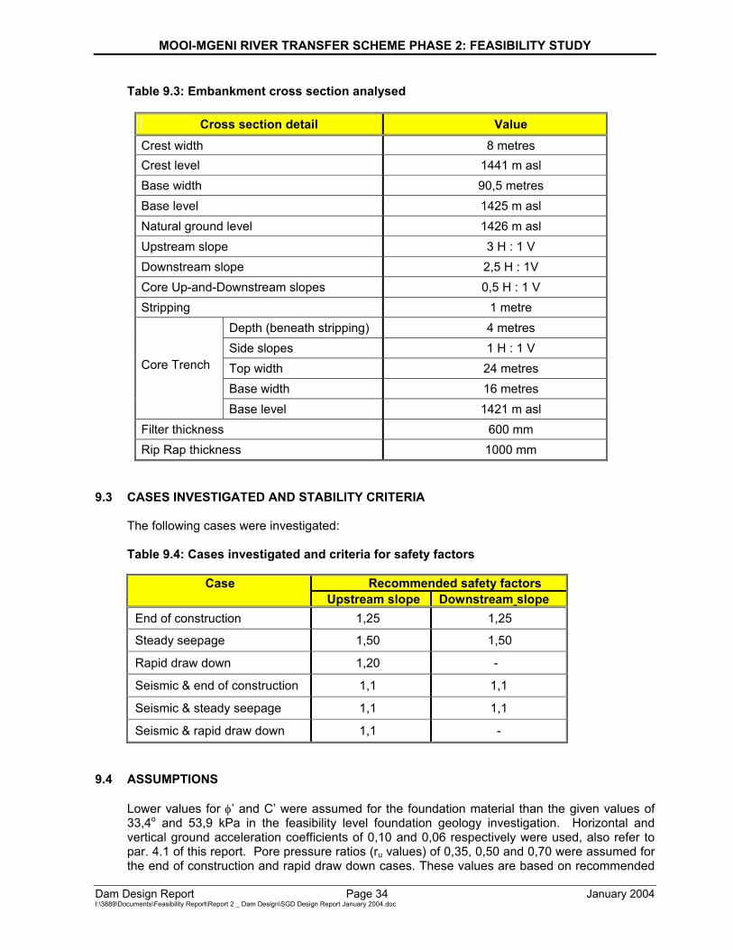
Table 9.3: Embankment cross section analysed
Cross section detail Value Crest width 8 metres Crest level 1441 m asl Base width 90,5 metres Base level 1425 m asl Natural ground level 1426 m asl Upstream slope 3 H : 1 V Downstream slope 2,5 H : 1V Core Up-and-Downstream slopes 0,5 H : 1 V Stripping 1 metre
Depth (beneath stripping) 4 metres Side slopes 1 H : 1 V Top width 24 metres Base width 16 metres
Core Trench
Base level 1421 m asl Filter thickness 600 mm Rip Rap thickness 1000 mm
9.3 CASES INVESTIGATED AND STABILITY CRITERIA The following cases were investigated: Table 9.4: Cases investigated and criteria for safety factors
Recommended safety factors Case Upstream slope Downstream slope
End of construction 1,25 1,25
Steady seepage 1,50 1,50
Rapid draw down 1,20 -
Seismic & end of construction 1,1 1,1
Seismic & steady seepage 1,1 1,1
Seismic & rapid draw down 1,1 -
9.4 ASSUMPTIONS Lower values for φ’ and C’ were assumed for the foundation material than the given values of 33,4o and 53,9 kPa in the feasibility level foundation geology investigation. Horizontal and vertical ground acceleration coefficients of 0,10 and 0,06 respectively were used, also refer to par. 4.1 of this report. Pore pressure ratios (ru values) of 0,35, 0,50 and 0,70 were assumed for the end of construction and rapid draw down cases. These values are based on recommended
MOOI-MGENI RIVER TRANSFER SCHEME PHASE 2: FEASIBILITY STUDY
Dam Design Report Page 35 January 2004 I:\3889\Documents\Feasibility Report\Report 2 _ Dam Design\SGD Design Report January 2004.doc
values as well as on values used for the stability analyses for the earth embankments of Qedusizi Dam. The recommended pore pressure ratio (ru) for the end of construction case is equal to the pore pressure coefficient (B), which have to be determined in the laboratory. This must therefore be determined in the laboratory during the final design stage. The moist density was assumed for the end of construction case. The recommended pore pressure ratio for the rapid draw down case is between 0,30 and 0,40, this must however be re-assessed during the final design stage. The saturated density was assumed for the rapid draw down case for the upstream slope. The seepage path for the steady seepage case was assumed to be the same as for a homogenous embankment, without a drainage system on an impervious foundation. This assumes that the drainage system is not functioning, and that all the seepage occurs through the embankment. This is however a conservative assumption and needs to be re-assessed during the final design stage on the basis of detailed and comprehensive seepage analyses. Moist and saturated densities were assumed above and beneath the waterline respectively.
9.5 STABILITY CALCULATIONS The critical slip circles for both the up and downstream slopes were obtained by means of the Fellenius Construction. Ten and seven slices were used for the analyses of the up and downstream slopes respectively. The safety factors against sliding were calculated by hand with the Bishop semi-rigorous solution, and verified with the Swedish circle (Fellenius) solution. Computer calculations were also performed to verify the hand calculations.
9.6 FINDINGS AND RESULTS
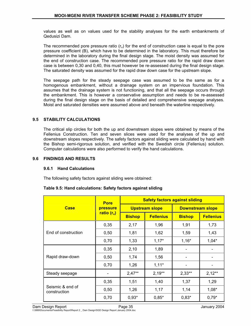
9.6.1 Hand Calculations The following safety factors against sliding were obtained: Table 9.5: Hand calculations: Safety factors against sliding
Safety factors against sliding
Upstream slope Downstream slope Case Pore
pressure ratio (ru)
Bishop Fellenius Bishop Fellenius
0,35 2,17 1,96 1,91 1,73
0,50 1,81 1,62 1,59 1,43 End of construction
0,70 1,33 1,17* 1,16* 1,04*
0,35 2,10 1,89 - -
0,50 1,74 1,56 - - Rapid draw-down
0,70 1,26 1,11* - -
Steady seepage - 2,47** 2,19** 2,33** 2,12**
0,35 1,51 1,40 1,37 1,29
0,50 1,26 1,17 1,14 1,08* Seismic & end of construction
0,70 0,93* 0,85* 0,83* 0,79*
MOOI-MGENI RIVER TRANSFER SCHEME PHASE 2: FEASIBILITY STUDY
Dam Design Report Page 36 January 2004 I:\3889\Documents\Feasibility Report\Report 2 _ Dam Design\SGD Design Report January 2004.doc
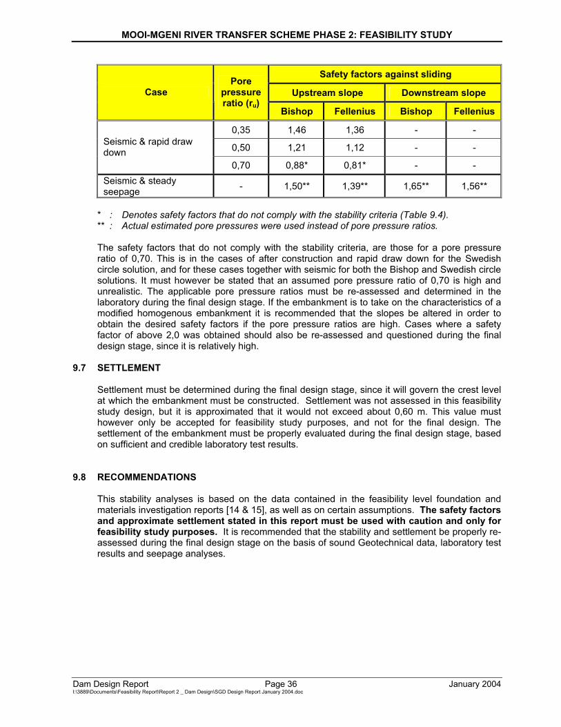
Safety factors against sliding
Upstream slope Downstream slope Case Pore
pressure ratio (ru)
Bishop Fellenius Bishop Fellenius
0,35 1,46 1,36 - -
0,50 1,21 1,12 - - Seismic & rapid draw down
0,70 0,88* 0,81* - - Seismic & steady seepage - 1,50** 1,39** 1,65** 1,56**
* : Denotes safety factors that do not comply with the stability criteria (Table 9.4). ** : Actual estimated pore pressures were used instead of pore pressure ratios. The safety factors that do not comply with the stability criteria, are those for a pore pressure ratio of 0,70. This is in the cases of after construction and rapid draw down for the Swedish circle solution, and for these cases together with seismic for both the Bishop and Swedish circle solutions. It must however be stated that an assumed pore pressure ratio of 0,70 is high and unrealistic. The applicable pore pressure ratios must be re-assessed and determined in the laboratory during the final design stage. If the embankment is to take on the characteristics of a modified homogenous embankment it is recommended that the slopes be altered in order to obtain the desired safety factors if the pore pressure ratios are high. Cases where a safety factor of above 2,0 was obtained should also be re-assessed and questioned during the final design stage, since it is relatively high.
9.7 SETTLEMENT
Settlement must be determined during the final design stage, since it will govern the crest level at which the embankment must be constructed. Settlement was not assessed in this feasibility study design, but it is approximated that it would not exceed about 0,60 m. This value must however only be accepted for feasibility study purposes, and not for the final design. The settlement of the embankment must be properly evaluated during the final design stage, based on sufficient and credible laboratory test results.
9.8 RECOMMENDATIONS This stability analyses is based on the data contained in the feasibility level foundation and materials investigation reports [14 & 15], as well as on certain assumptions. The safety factors and approximate settlement stated in this report must be used with caution and only for feasibility study purposes. It is recommended that the stability and settlement be properly re-assessed during the final design stage on the basis of sound Geotechnical data, laboratory test results and seepage analyses.
MOOI-MGENI RIVER TRANSFER SCHEME PHASE 2: FEASIBILITY STUDY
Dam Design Report Page 37 January 2004 I:\3889\Documents\Feasibility Report\Report 2 _ Dam Design\SGD Design Report January 2004.doc
10 OUTLET WORKS
In accordance with DWAF standard policy, the proposed Spring Grove Dam will be equipped with easily accessible, reliable, safe and easily maintained outlet works, that assure the release into the downstream rivercourse and pumping station of water of adequate quantity and quality.
10.1 LAYOUT The outlet works is to be located on the right flank and consists of a right-hand and a left-hand portion. The right-hand portion houses the pumping station outlets and the left-hand houses the river outlets. (See drawings 134 521/00 and 137 070/01.)
10.2 RIVER OUTLET The river outlets will be provided to meet the downstream requirements. The inlet tower with butterfly valve controlled intakes at 5m vertical intervals in a dry well will incorporate two separate shaft pipes and will be furnished with a staircase and a gantry crane to allow valves to be removed.
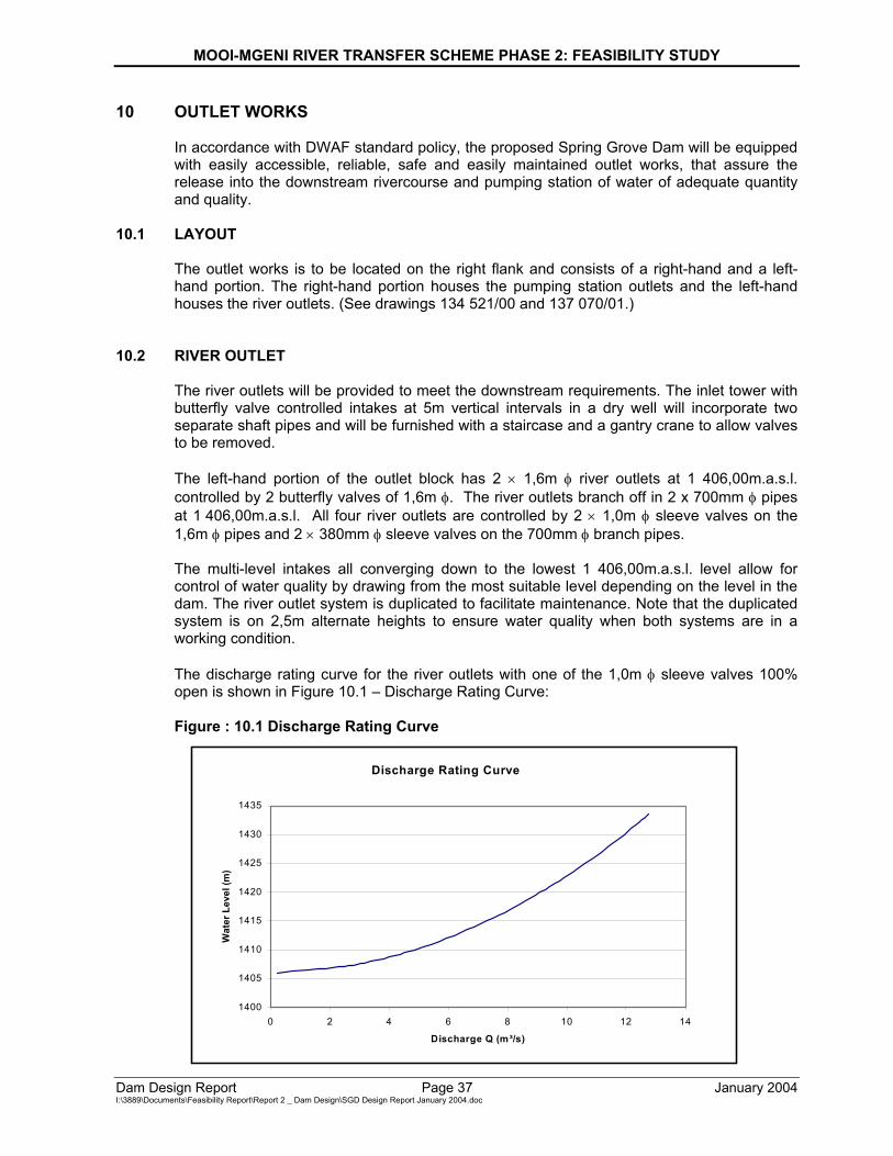
The left-hand portion of the outlet block has 2 × 1,6m φ river outlets at 1 406,00m.a.s.l. controlled by 2 butterfly valves of 1,6m φ. The river outlets branch off in 2 x 700mm φ pipes at 1 406,00m.a.s.l. All four river outlets are controlled by 2 × 1,0m φ sleeve valves on the 1,6m φ pipes and 2 × 380mm φ sleeve valves on the 700mm φ branch pipes.
The multi-level intakes all converging down to the lowest 1 406,00m.a.s.l. level allow for control of water quality by drawing from the most suitable level depending on the level in the dam. The river outlet system is duplicated to facilitate maintenance. Note that the duplicated system is on 2,5m alternate heights to ensure water quality when both systems are in a working condition.
The discharge rating curve for the river outlets with one of the 1,0m φ sleeve valves 100% open is shown in Figure 10.1 – Discharge Rating Curve: Figure : 10.1 Discharge Rating Curve
Discharge Rating Curve
1400
1405
1410
1415
1420
1425
1430
1435
0 2 4 6 8 10 12 14
Discharge Q (m³/s)
Wat
er L
evel
(m)
MOOI-MGENI RIVER TRANSFER SCHEME PHASE 2: FEASIBILITY STUDY
Dam Design Report Page 38 January 2004 I:\3889\Documents\Feasibility Report\Report 2 _ Dam Design\SGD Design Report January 2004.doc
10.3 PUMPING STATION OUTLETS
The right-hand portion of the outlet block has 2 × 1,0m φ pumping station outlets at 1 406,00m.a.s.l controlled by 2 butterfly valves of 1,0m φ.
The multi-level intakes all converging down to the lowest 1 406,00 level allow for control of water quality by drawing from the most suitable level depending on the level in the dam. One single pipe can convey the required 5,5m³/s flow through the pumping station. The pumping station outlet system is duplicated to facilitate maintenance. Note that the duplicated system is on 2,5m alternate heights to ensure water quality when both systems are in a working condition.
10.4 OPERATING RULE FOR RELEASES
When Spring Grove Dam has been constructed, it needs to be able to release sufficient water so that the March freshette of 40m³/s as measured at Mearns Weir can be achieved. The contribution from the Little Mooi River needs to be taken into account so as to limit releases from Spring Grove Dam. The need to construct new gauging stations on the Little Mooi River must be addressed at the implementation stage.

MOOI-MGENI RIVER TRANSFER SCHEME PHASE 2: FEASIBILITY STUDY
Dam Design Report Page 39 January 2004 I:\3889\Documents\Feasibility Report\Report 2 _ Dam Design\SGD Design Report January 2004.doc
11 CONSTRUCTION MATERIALS 11.1 MATERIALS AVAILABILITY
Seven potential borrow areas (areas A to G) were identified for embankment materials within the proposed dam basin during the feasibility level construction materials investigation [15]. These areas are located between 1 to 3,5 km upstream from the proposed dam wall. Five potential borrow areas contain an estimated total of 1 062 000 m3 of impervious material which complies with typical specifications for core material. The remaining two borrow areas contain an estimated total of 832 000 m3 of transition material. Since all the potential borrow areas investigated are located within the proposed dam basin, rehabilitation of these areas should not be a major concern.
Two potential quarry sites for aggregate and rip-rap in dolerite were investigated. Firstly a site on the farm Spring Vale and secondly a disused KwaZulu Natal Provincial Administration (KZNPA) quarry. Both these sites are located within 1,5 km from the proposed dam site. Preliminary calculations for the potential Spring Vale quarry site indicated the availability of approximately 900 000 m3 of useable rock. Overburden volumes are approximately 300 000 m3. For the disused NPA quarry preliminary calculations indicated the availability of 23 000 m3 of upper fine-grained dolerite. Approximately 8 000 m3 of overburden will require removal. Constraints on the development of either quarry options include the proximity of the main Johannesburg - Durban railway line, the R103 road between Rosetta and Nottingham Road, as well as the water transfer pipeline from the Mearns Pumping Station. For the disused NPA quarry a further major limitation is the proximity of residential development.
A locality map, indicating the positions of the above mentioned borrow areas and quarry sites, is included in Annexure C2 of this report.
11.2 CONCRETE
11.2.1 Cementitious Materials
• Cement
Cementitious materials for the concrete will comprise a blend of Portland Cement (PC) and an extender. The extender will either be fly-ash (FA) or granulated ground blast furnace slag (GGBS). The percentage of extender to be used in the concrete mix will be determined by results of the trial mixes conducted during the implementation stage. The PC used in the concrete will comply with the requirements of SABS 471 or ENV197-1 CEM 132,5 or 32,5R.
• Fly-ash
The fly-ash (FA) will comply with the requirements of SABS 1491 – Part 2.
• Slagment
The granulated ground blast furnace slag (GGBS) will comply with the requirements of SABS 1491 – Part 1.
MOOI-MGENI RIVER TRANSFER SCHEME PHASE 2: FEASIBILITY STUDY
Dam Design Report Page 40 January 2004 I:\3889\Documents\Feasibility Report\Report 2 _ Dam Design\SGD Design Report January 2004.doc
Economic considerations will dictate the utilisation of Slagment or Fly-ash.
11.2.2 Fine Aggregate
• Natural
Investigations into the potential quarry site on the farm Spring Vale revealed the absence of sand suitable for use as fine aggregate. Investigations into the disused NPA quarry site revealed that the fine-grained dolerite can be considered suitable. However, developing this quarry only for the fine-grained material was considered impractical, due to the large area requiring development.
• Mechanical produced sand
From the test results obtained, it is evident that crusher sands produced from the dolerite at the Spring Vale quarry will generally satisfy DWAF specifications.
11.2.3 Coarse Aggregate
• Quarries
Five boreholes were drilled at the potential Spring Vale quarry site. The dolerite sill is approximately 33 m thick. Three zones may be recognised, including fine grained horizons associated with the upper and lower contact zones, respectively, separated by a meduim to coarse grained zone. Overburden comprises shallow topsoil underlain by completely weathered or moderately weathered sandstone/siltstone strata. Overburden thickness varies between 3 to 10m. Mineralogical analyses reveal the only potentially deleterious minerals to comprise talc, laumontite and smectite. The smectite content is typically less than 9% but occasionally values up to 14 to 17% were recorded. Samples subjected to slake durability tests showed very little disintegration. Other tests, including absorption, sulphate soundness and crushing strengths, indicate compliance with specifications for coarse aggregate.
The disused KZNPA quarry had previously been investigated by exploratory drilling, while limited testing had also been carried out. Further samples were submitted for mineralogical analyses and durability testing. The dolerite sill here is 28 m thick. Fine-grained zones with thickness between 4 to 9m are associated with the respective upper and lower contacts. The central coarse-grained zone is between 11 to 17m in thickness. Overburden thickness varies between 0,5 and 1,5m. Previous slake durability tests indicated the coarse-grained dolerite was non-durable. The single mineralogical analyses revealed 29% montmorillonite. In contrast the durable fine-grained dolerite contained zero montmorillonite. Recent mineralogical analyses of the upper fine-grained zone revealed low smectite contents of 1 to 2%. Both slake durability tests as well as Brazilian wetting and drying tests confirm this fine-grained dolerite is durable. Previous investigations however concluded that this site was unsuitable as an aggregate source.
• Commercial sources
It seems unlikely that aggregates will need to be supplemented from commercial sources.
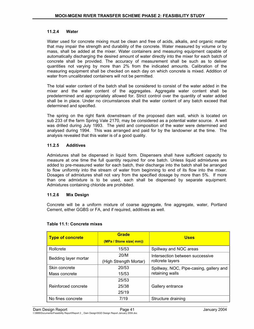
MOOI-MGENI RIVER TRANSFER SCHEME PHASE 2: FEASIBILITY STUDY
Dam Design Report Page 41 January 2004 I:\3889\Documents\Feasibility Report\Report 2 _ Dam Design\SGD Design Report January 2004.doc
11.2.4 Water
Water used for concrete mixing must be clean and free of acids, alkalis, and organic matter that may impair the strength and durability of the concrete. Water measured by volume or by mass, shall be added at the mixer. Water containers and measuring equipment capable of automatically discharging the desired amount of water directly into the mixer for each batch of concrete shall be provided. The accuracy of measurement shall be such as to deliver quantities not varying by more than 2% from the indicated amounts. Calibration of the measuring equipment shall be checked on each day on which concrete is mixed. Addition of water from uncalibrated containers will not be permitted. The total water content of the batch shall be considered to consist of the water added in the mixer and the water content of the aggregates. Aggregate water content shall be predetermined and appropriately allowed for. Strict control over the quantity of water added shall be in place. Under no circumstances shall the water content of any batch exceed that determined and specified. The spring on the right flank downstream of the proposed dam wall, which is located on sub 233 of the farm Spring Vale 2170, may be considered as a potential water source. A well was drilled during July 1993. The yield and composition of the water were determined and analysed during 1994. This was arranged and paid for by the landowner at the time. The analysis revealed that this water is of a good quality.
11.2.5 Additives
Admixtures shall be dispensed in liquid form. Dispensers shall have sufficient capacity to measure at one time the full quantity required for one batch. Unless liquid admixtures are added to pre-measured water for each batch, their discharge into the batch shall be arranged to flow uniformly into the stream of water from beginning to end of its flow into the mixer. Dosages of admixtures shall not vary from the specified dosage by more than 5%. If more than one admixture is to be used, each shall be dispensed by separate equipment. Admixtures containing chloride are prohibited. 11.2.6 Mix Design
Concrete will be a uniform mixture of coarse aggregate, fine aggregate, water, Portland Cement, either GGBS or FA, and if required, additives as well.
Table 11.1: Concrete mixes
Type of concrete Grade (MPa / Stone size( mm))
Uses
Rollcrete 15/53 Spillway and NOC areas
Bedding layer mortar 20/M
(High Strength Mortar) Intersection between successive rollcrete layers
Skin concrete Mass concrete
20/53 15/53
Spillway, NOC, Pipe-casing, gallery and retaining walls
Reinforced concrete 25/53 25/38 25/19
Gallery entrance
No fines concrete 7/19 Structure draining
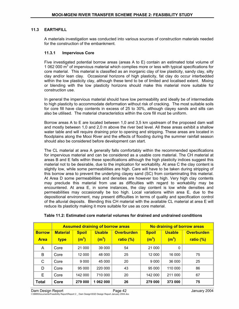
MOOI-MGENI RIVER TRANSFER SCHEME PHASE 2: FEASIBILITY STUDY
Dam Design Report Page 42 January 2004 I:\3889\Documents\Feasibility Report\Report 2 _ Dam Design\SGD Design Report January 2004.doc
11.3 EARTHFILL
A materials investigation was conducted into various sources of construction materials needed for the construction of the embankment. 11.3.1 Impervious Core Five investigated potential borrow areas (areas A to E) contain an estimated total volume of 1 062 000 m3 of impervious material which complies more or less with typical specifications for core material. This material is classified as an inorganic clay of low plasticity, sandy clay, silty clay and/or lean clay. Occasional horizons of high plasticity, fat clay do occur interbedded within the low plasticity clay, although these tend to be of limited and localised extent. Mixing or blending with the low plasticity horizons should make this material more suitable for construction use. In general the impervious material should have low permeability and ideally be of intermediate to high plasticity to accommodate deformation without risk of cracking. The most suitable soils for core fill have clay contents in excess of 25 to 30%, although clayey sands and silts can also be utilised. The material characteristics within the core fill must be uniform. Borrow areas A to E are located between 1,0 and 3,5 km upstream of the proposed dam wall and mostly between 1,0 and 2,0 m above the river bed level. All these areas exhibit a shallow water table and will require draining prior to opening and stripping. These areas are located in floodplains along the Mooi River and the effects of flooding during the summer rainfall season should also be considered before development can start.
The CL material at area A generally falls comfortably within the recommended specifications for impervious material and can be considered as a usable core material. The CH material at areas B and E falls within these specifications although the high plasticity indices suggest this material not to be desirable, due to the implication for workability. At area C the clay content is slightly low, while some permeabilities are high. Care will have to be taken during stripping of this borrow area to prevent the underlying clayey sand (SC) from contaminating this material. At Area D some permeabilities and densities are however too high. Very high clay contents may preclude this material from use as difficulties with regard to workability may be encountered. At area E, in some instances, the clay content is low while densities and permeabilities may occasionally be too high. Local variations within area E, due to the depositional environment, may present difficulties in terms of quality and specification control of the alluvial deposits. Blending this CH material with the available CL material at area E will reduce its plasticity making it more suitable for use as core material. Table 11.2: Estimated core material volumes for drained and undrained conditions
Assumed draining of borrow areas No draining of borrow areas Borrow
Area Material
type Spoil (m3)
Usable (m3)
Overburden ratio (%)
Spoil (m3)
Usable (m3)
Overburden ratio (%)
A Core 21 000 39 000 54 21 000 0
B Core 12 000 48 000 25 12 000 16 000 75
C Core 9 000 45 000 20 9 000 36 000 25
D Core 95 000 220 000 43 95 000 110 000 86
E Core 142 000 710 000 20 142 000 211 000 67
Total Core 279 000 1 062 000 26 279 000 373 000 75
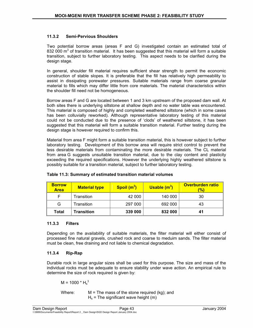
MOOI-MGENI RIVER TRANSFER SCHEME PHASE 2: FEASIBILITY STUDY
Dam Design Report Page 43 January 2004 I:\3889\Documents\Feasibility Report\Report 2 _ Dam Design\SGD Design Report January 2004.doc
11.3.2 Semi-Pervious Shoulders
Two potential borrow areas (areas F and G) investigated contain an estimated total of 832 000 m3 of transition material. It has been suggested that this material will form a suitable transition, subject to further laboratory testing. This aspect needs to be clarified during the design stage. In general, shoulder fill material requires sufficient shear strength to permit the economic construction of stable slopes. It is preferable that the fill has relatively high permeability to assist in dissipating porewater pressures. Suitable materials range from coarse granular material to fills which may differ little from core materials. The material characteristics within the shoulder fill need not be homogeneous. Borrow areas F and G are located between 1 and 3 km upstream of the proposed dam wall. At both sites there is underlying siltstone at shallow depth and no water table was encountered. This material is composed of highly and completed weathered siltstone (which in some cases has been colluvially reworked). Although representative laboratory testing of this material could not be conducted due to the presence of ‘clods’ of weathered siltstone, it has been suggested that this material will form a suitable transition material. Further testing during the design stage is however required to confirm this. Material from area F might form a suitable transition material, this is however subject to further laboratory testing. Development of this borrow area will require strict control to prevent the less desirable materials from contaminating the more desirable materials. The CL material from area G suggests unsuitable transition material, due to the clay content and plasticity exceeding the required specifications. However the underlying highly weathered siltstone is possibly suitable for a transition material, subject to further laboratory testing. Table 11.3: Summary of estimated transition material volumes
Borrow Area Material type Spoil (m3) Usable (m3) Overburden ratio
(%) F Transition 42 000 140 000 30
G Transition 297 000 692 000 43
Total Transition 339 000 832 000 41
11.3.3 Filters
Depending on the availability of suitable materials, the filter material will either consist of processed fine natural gravels, crushed rock and coarse to meduim sands. The filter material must be clean, free draining and not liable to chemical degradation.
11.3.4 Rip-Rap
Durable rock in large angular sizes shall be used for this purpose. The size and mass of the individual rocks must be adequate to ensure stability under wave action. An empirical rule to determine the size of rock required is given by:
M = 1000 * Hs3
Where: M = The mass of the stone required (kg); and
Hs = The significant wave height (m)
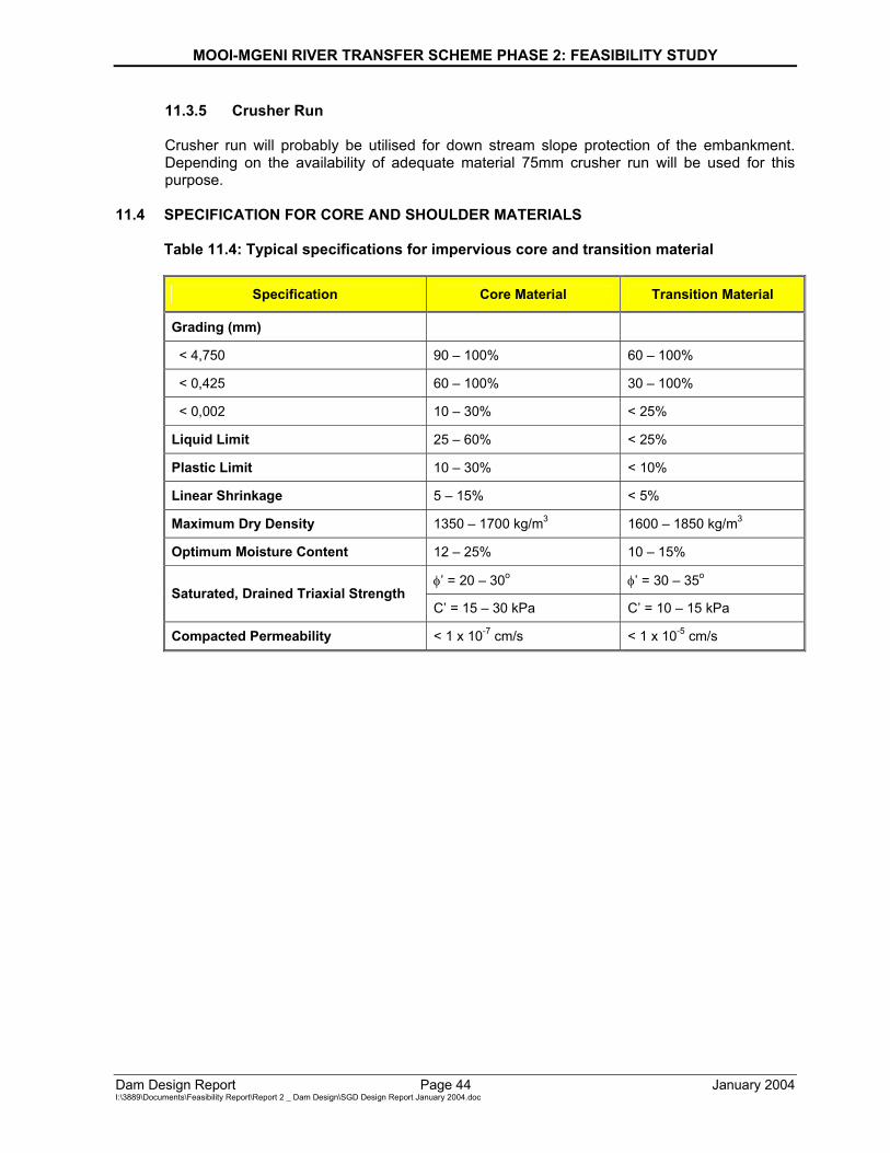
MOOI-MGENI RIVER TRANSFER SCHEME PHASE 2: FEASIBILITY STUDY
Dam Design Report Page 44 January 2004 I:\3889\Documents\Feasibility Report\Report 2 _ Dam Design\SGD Design Report January 2004.doc
11.3.5 Crusher Run
Crusher run will probably be utilised for down stream slope protection of the embankment. Depending on the availability of adequate material 75mm crusher run will be used for this purpose.
11.4 SPECIFICATION FOR CORE AND SHOULDER MATERIALS
Table 11.4: Typical specifications for impervious core and transition material
Specification Core Material Transition Material
Grading (mm)
< 4,750 90 – 100% 60 – 100%
< 0,425 60 – 100% 30 – 100%
< 0,002 10 – 30% < 25%
Liquid Limit 25 – 60% < 25%
Plastic Limit 10 – 30% < 10%
Linear Shrinkage 5 – 15% < 5%
Maximum Dry Density 1350 – 1700 kg/m3 1600 – 1850 kg/m3
Optimum Moisture Content 12 – 25% 10 – 15%
φ’ = 20 – 30o φ’ = 30 – 35o Saturated, Drained Triaxial Strength
C’ = 15 – 30 kPa C’ = 10 – 15 kPa
Compacted Permeability < 1 x 10⁻⁷ cm/s < 1 x 10⁻⁵ cm/s
MOOI-MGENI RIVER TRANSFER SCHEME PHASE 2: FEASIBILITY STUDY
Dam Design Report Page 45 January 2004 I:\3889\Documents\Feasibility Report\Report 2 _ Dam Design\SGD Design Report January 2004.doc
12 MISCELLANEOUS DAM DESIGN ISSUES 12.1 GROUTING
12.1.1 Need for Grouting
The Feasibility Level Foundation Investigation [14] yielded that the rock permeabilities are generally very low and that the majority of the rock mass can be considered to be nearly impervious. Closely jointed and brecciated zones are sites of higher water take and will therefore require grouting to reduce permeability. Contacts between the dolerite and sedimentary strata are generally open and fractured and it is recommended that grouting be attempted to intersect all these contacts. The fault on the left flank is likely to exhibit high permeability. Grouting will be required where lugeon values of 3 are exceeded. Water tests must be conducted over the total length of the rollcrete wall in order to establish whether grouting is necessary.
12.1.2 Curtain Grouting
The objective with curtain grouting will be to form a partial cut-off in order to limit seepage, and to modify the downstream pressure regime. The curtain depth is frequently comparable to the height of the structure. Curtain grouting is common practice for concrete dams, and it was considered for costing purposes. Holes were assumed to be spaced at 2 m intervals, and the depth was assumed to be 75% of the height of the structure in a particular area. Holes were also assumed to be sloped 20o from the vertical towards the upstream face of the dam wall. Curtain grouting was assumed for the full lengths of the right flank non-overspill crest and the spillway, as well as for 50% of the length of the left flank non-overspill crest. The aforementioned assumptions must however be verified during the final design stage. 12.1.3 Consolidation Grouting
The objective with consolidation grouting will be to stiffen and consolidate the rock in the critical contact zone immediately beneath the dam. It will also assist in reducing seepage in the contact zone, where the rock may be more fissured or weathered than at greater depths. Care is required over the grout injection pressures employed in order to avoid disruption, fracturing and the opening up of horizontal fissures. Consolidation grouting is common practice for concrete dams, and it was therefore considered for costing purposes. Primary holes were assumed to be drilled vertically on a 4 m grid spacing from the upstream to the downstream side of the excavation. The secondary holes were assumed to be drilled halfway between the primary holes. The depths of the holes were assumed to be 10% of the height of the structure for the river section, and an average of 5 m for the remainder of the concrete structure in a particular area. These depths were assumed, based on the borehole logs contained in the Feasibility Level Foundation Investigation Report [14]. Consolidation grouting was assumed for the full lengths of the right flank non-overspill crest and the spillway, as well as for 75% of the length of the left flank non-overspill crest. The aforementioned assumptions must however be verified during the final design stage.
MOOI-MGENI RIVER TRANSFER SCHEME PHASE 2: FEASIBILITY STUDY
Dam Design Report Page 46 January 2004 I:\3889\Documents\Feasibility Report\Report 2 _ Dam Design\SGD Design Report January 2004.doc
12.1.4 Grouting Specifications
The standard grouting specifications of the Department of Water Affairs and Forestry, DWA 0510 will be specified, and apply to all grouting work during construction.
12.2 DRAINAGE
The objective with drainage is to effect foundation uplift relief by a line of drainage holes, in the gallery, located closely downstream of the grout curtain. Drainage is common practise for concrete dams, and it was therefore considered for costing purposes. It was assumed that drainage holes, diameter 102 mm, were drilled from the gallery to approximately 50% of the vertical depth of the curtain grout holes in a particular area. Spacing of the drainage holes was assumed to be at 3 m centres. The aforementioned assumptions must however be verified during the final design stage.
12.3 GALLERY
A low level inspection gallery is proposed for the bulk of the concrete section in order to collect seepage inflow from the uplift relief drains. The gallery will also serve to provide access to instrumentation, internal discharge valves and pipework. It is proposed that the gallery have a total inside width and height of at least 2,5 and 3 m respectively, with 1,75 m high vertical walls and the roof to be formed by means of precasted concrete arches. An arch in the form of a half circle, with an inside radius of 1,25 m, is proposed. A minimum concrete thickness of 1,5 m is proposed between the rock foundation and the gallery drain. A minimum concrete thickness of 5 m is proposed between the gallery and the upstream face of the structure. A 300 mm wide drainage channel is proposed, together with a sump and outlet pipe, in order to drain seepage inflow from the uplift relief drains. A Parshall Flume is proposed inside the gallery in order to measure seepage. Location markers are proposed inside the gallery for monitoring and inspection purposes. All electrical wiring installed inside the gallery will be safe and well secured. Security gates are proposed at the gallery entrances for safety and security purposes.
12.4 HANDRAILS
It is proposed that the handrails to be used are similar to those in use at existing DWAF Dams. It is likely that the handrails will also form part of the lightening protection system.
MOOI-MGENI RIVER TRANSFER SCHEME PHASE 2: FEASIBILITY STUDY
Dam Design Report Page 47 January 2004 I:\3889\Documents\Feasibility Report\Report 2 _ Dam Design\SGD Design Report January 2004.doc
13 CONSTRUCTION 13.1 PROGRAMME
A proposed construction programme is contained in Annexure E of this report. This programme will however be likely to change during the final design stage as well as due to the foreseen budget allocation for construction purposes.
13.2 CONCRETE CONSTRUCTION
13.2.1 Roller Compacted Concrete
For construction below the adjacent natural ground level, a series of ramps will have to be cut into the sides of the excavation. When construction has commenced above the adjacent natural ground level, access can be obtained via left flank non-overspill crest or via constructed ramps on the upstream side of the constructed rollcrete. These ramps will however have to be maintained and increased as construction progresses. Sufficient turning space for construction equipment and trucks must be provided for. After excavation all loose material and rocks must be identified and removed, whereafter the rock surface must be washed by means of an air and water jet. After washing, the rock surface must be covered with a 20 mm thick bedding layer consisting of a mortar mix. Sudden steps of 300 mm or more must be smoothed out by using a filler concrete, with the same mix proportions as for the skin concrete. This is necessary, as compaction of rollcrete in these areas will otherwise be impossible. All of the above mentioned actions should be performed in pre-defined areas of the foundation surface.
Rollcrete will be mixed on site and transported by means of dumpers to the dam wall. After the rollcrete is dumped in place, it will have to be spread by means of a dozer and then the rollcrete must be compacted. The desired rollcrete thickness after compaction must be 250 mm per layer. Rollcreting must be done in horizontal longitudinal layers. A crossfall, in the order of 250 mm, towards the upstream face should also be considered in order to enhance shear resistance between consecutive layers. After a layer has been placed, the total surface area of the layer must be greencut before the rollcrete sets too hard. This must be done within 12 hours after the last rollcrete was placed. Greencutting must only be performed at the end of the placement of a layer and not during the placement of a layer. It must also be insured that the following layer of rollcrete is placed before the previous layer has fully set. Before rollcreting of a new layer commences, a mortar-bedding layer must be spread over the surface of the previous layer. This will help against the tendency of turning vehicles dislodging aggregates on the surface of the previous layer. A shutter system will need to be in place for both the upstream and downstream faces. On the downstream face the shutters can be moved and re-erected by hand from the previous to the next step. On the upstream face a hanging platform must be provided in order for the shutters to be moved and re-erected. Proper anchoring and supporting systems must be provided for the shutters. The construction of a test section for rollcrete construction purposes should also be considered, as it might be required. During construction the following tests must be performed daily on the rollcrete: • VB test;
• Cube strength;
MOOI-MGENI RIVER TRANSFER SCHEME PHASE 2: FEASIBILITY STUDY
Dam Design Report Page 48 January 2004 I:\3889\Documents\Feasibility Report\Report 2 _ Dam Design\SGD Design Report January 2004.doc
• Temperature at point of discharge, and
• Compaction of the wall, with a TROXLER.
13.2.2 Skin Concrete
Skin concrete must be transported in mixer trucks to the dam wall. At the start of the placement of a layer of skin concrete, the area where the skin concrete is to be placed must first be covered with a bedding mix. The mixer trucks must discharge the skin concrete, with the aid of its chute, against the shutters. The minimum desired width and thickness, after vibration, are 600 mm and 250 mm respectively. Skin concrete must be placed prior to the placement of a new layer of rollcrete. At the vertical crack formers the skin concrete must be placed wider (approx. 900mm). After discharging the skin concrete, prior to rollcreting, the skin concrete must first be compacted by means of vibrators. It must also be ensured that a proper bond is obtained between the skin concrete and the rollcrete. The placing of skin concrete can be regarded as one of the most critical aspects of the overall rollcreting operation, as this could easily cause a delay. This especially applies when the surface becomes too narrow for multiple vehicles to work in.
13.2.3 Mass Concrete
The conventional concrete specifications, as compiled by the Department of Water Affairs and Forestry, will apply as contained in Annexure F of this report.
13.2.4 Reinforced Concrete
The conventional concrete specifications, as compiled by the Department of Water Affairs and Forestry, will apply as contained in Annexure F of this report.
13.2.5 Drainage Gallery
It is recommended that roof section of the gallery be constructed from pre-cast concrete sections, and covered with skin concrete prior to the placement of rollcrete. The side-walls of the gallery can be constructed from skin concrete. Care must be taken with the anchoring of the shutters prior to rollcreting, especially for the pre-cast roof section.
13.2.6 Ogee Capping
Rollcrete will be placed up to the level where the cap must start. The bulk of the concrete to be used for ogee capping will probably be similar to the skin concrete. It is recommended that finer concrete be used to construct the outer layer of the capping, since this will enhance the finish of the surface area.
13.3 EARTH EMBANKMENT CONSTRUCTION
13.3.1 Impervious Core
The core trench must be excavated after the area for the embankment is cleared and stripped. After the core trench is excavated and inspected the construction of the core can commence. The contact area must be properly prepared according to specifications. These specifications must be finalised during the final design stage, before the start of construction. Normally the
MOOI-MGENI RIVER TRANSFER SCHEME PHASE 2: FEASIBILITY STUDY
Dam Design Report Page 49 January 2004 I:\3889\Documents\Feasibility Report\Report 2 _ Dam Design\SGD Design Report January 2004.doc
preparation of the contact area involves the construction of cut-off’s, ploughing and treatment of the foundation with lime and/or gypsum.
The clay will need to be transported from the borrow area/s with dumpers. Spreading can be done by means of dozers and/or graders depending on the availability of construction equipment. It is recommended that all layers be placed 300 mm thick before being compacted. It is recommended that all clay be placed at optimum moisture plus 3 %. Water must be added to the clay after the clay is spread, the clay must then be ploughed to ensure a uniform moisture content before compaction commences. Should the surface be smooth, after compaction, it must be roughened by means of ploughing before commencing with placement of the next layer. The previous layer must also be watered before the next layer is placed.
Every time when a new texture of clay is obtained from the borrow area/s, the optimum moisture must be determined by means of Proctor tests at the site laboratory. Density and moisture content measurements must also be done at several positions on each layer, before the placement of a following layer can commence. These measurements must be done by means of a nuclear densometer (Troxler or Humbolt). Regular gradings must also be performed in order to ensure that the correct clay is used.
13.3.2 Semi Pervious Shoulders
The construction procedures for the semi pervious shoulders are similar to those for the impervious core. The foundation surface must however be properly prepared and it must be ensured that it is free from any organic materials.
13.3.3 Filters
The fill levels must first be brought up to the level of the blanket drain, whereafter the filter sand can be spread over the required area. Compaction must be accomplished by means of saturating the sand and then by rolling it with a vibratory roller. It is recommended that the chimney drain be constructed by means of trenching. The fill is first completed over the full width whereafter a trench can be excavated by means of a TLB or a backhoe fitted with a 600 mm wide bucket. The trench can then be filled with the filter sand, whereafter the sand must be saturated and compacted. Compaction can be accomplished by means of driving the wheels of a fully loaded dumper on the trench. The positions where the blanket and chimney drains are to be terminated must be established during the final design stage. 13.3.4 Upstream Rip - Rap Slope Protection
The upstream slope must first be prepared by removing all stones and smoothing the surface. After the preparation of the upstream slope a 200 to 300 mm layer of sand can be spread, whereafter a 200 to 300 mm layer of crushed gravel can be spread on the sand. The rip rap can then be dumped on to the surface by means of tippers or any other appropriate construction equipment. The thickness of the rip rap will be in the order of 750 to 1000 mm.
13.3.5 Downstream Crusher Run Slope Protection
The downstream slope must first be prepared by removing all stones and smoothing the surface. After the preparation of the downstream slope a 300 mm layer of 75 mm crusher run can be spread. The crusher run can be dumped on the surface by means of tippers or any other appropriate construction equipment.
MOOI-MGENI RIVER TRANSFER SCHEME PHASE 2: FEASIBILITY STUDY
Dam Design Report Page 50 January 2004 I:\3889\Documents\Feasibility Report\Report 2 _ Dam Design\SGD Design Report January 2004.doc
13.3.6 Toe Drain After the fill has reached the toe drain levels, the toe drain must be constructed. The rock to be used for the toe drain is to be dumped at stockpiles by means of tippers. A front-end loader fitted with a selection bucket must then be used to select the correct grading for the rockfill. The final placing of the rockfill can mainly be done by hand. The gravel can be placed by means of a front-end loader.
13.4 FOUNDATIONS
13.4.1 Foundations for Concrete Sections
Upon completion of the excavations over sections, a detailed survey of the foundation must be compiled. It is recommended that a 2 m grid be used for this purpose. The surface must then be finally cleaned by means of an air and water jet. Clay in the vertical joints, if any, must be removed as deep as possible and replaced with the slush (bedding layer) used on the foundation surface before rollcreting commences. The installation of waterstops, void formers and crack inducers will also be required, the details will however need to be established during the final design stage. The foundation will need to be thoroughly inspected before any concreting and/or rollcreting commences.
13.4.2 Foundation for Earth Embankment
The core trench must be excavated to levels where the material is deemed to be suitable. The feasibility level investigation suggests 5 m, but this must however be confirmed. The approved professional person must approve the excavated foundation, and it must be mapped before embankment construction commences. The excavation of approximately 1 m (stripping) for the semi pervious shoulders must be free from any organic materials (e.g. vegetation).
13.5 BACKFILL
Suitable excavated materials must be stockpiled on the downstream side of the structure for usage as backfill material. The excavation must be done in such a manner to allow for sufficient space between the rollcrete structure and the undisturbed natural soil. This is necessary to ensure that proper construction equipment can be accommodated in order to perform proper back filling. On the downstream side it must be ensured that drainage water is diverted away from the structure. The permeability of the backfill material must also be considered, and must be modified if deemed necessary. A substantial amount of back filling will also be required on the left flank in order to cover a significant portion of the concrete (see drawing Reg. No. 133964/00). It must be ensured that the back filled slope on the left flank is stable. Stabilisation of this slope, if required, will increase the construction costs.
13.6 LABOUR INTENSIVE CONSTRUCTION
Labour intensive construction should be investigated and considered during the final design stage. Areas where labour intensive construction could possibly be considered are: • Earth embankment construction;
• Slope protection;
• Back filling; and
• Finishing and landscaping.
MOOI-MGENI RIVER TRANSFER SCHEME PHASE 2: FEASIBILITY STUDY
Dam Design Report Page 51 January 2004 I:\3889\Documents\Feasibility Report\Report 2 _ Dam Design\SGD Design Report January 2004.doc
Labour intensive construction should however only be considered after detailed studies and cost comparisons have been performed. It is therefore recommended that possible areas where labour intensive construction can probably be utilised, be properly investigated, and that the decision to utilise labour intensive construction be based on the results of these investigations.
13.7 RIVER DIVERSION
It is recommended that the river be diverted via the outlet works. The construction of the 60 m spillway should also be the last portion of the dam to be constructed, during the last dry season of the construction period. The river diversion should be able to accommodate the 1:5 year flood. The final layout of the river diversion and cofferdam must be established during the final design stage. The cofferdam will probably consist of a temporary concrete structure in the river section, whilst the conduit towards the outlet works will be constructed from earth fill. Wing walls must however be provided between the concrete in the river section and the earth fill, as well as between the outlet works and the earth fill. This is to ensure proper bonding between the earth fill and the concrete. Concreting in the river section will most probably be done by means of flow concrete, used for under water construction purposes. Before the flow concrete is placed it must be ensured that a proper foundation is prepared to accommodate the concrete. Extreme care must be taken with the design and construction of the river diversion works during the final design stage.
13.8 BORROW AREAS
According to the feasibility level materials availability investigation report, de-watering of the potential borrow areas will be required before stripping and excavations can commence. According to the above-mentioned investigation all the potential borrow areas are situated upstream of the proposed dam wall and therefore a minimum, if any, landscaping will be required.
13.9 QUARRIES
The potential quarry sites are situated downstream of the proposed dam wall, and landscaping will therefore be required. Removed topsoil will have to be stockpiled for landscaping purposes. During the excavation of the quarry site, it must be ensured that the topsoil side slopes are stable. A ramp will need to be cut in order for the stone to be removed from the quarry. After the required amount of stone has been removed from the quarry, the sides must be sloped to approximately 4 H : 1 V, by using the excavated topsoil. These slopes must be seeded in order to supplement the growth of natural vegetation. The quarry must also be properly fenced and secured in order to minimise the risk to people and animals.
13.10 QUALITY CONTROL
13.10.1 Concrete
The following tests must be performed daily on the rollcrete: • VB test;
• Cube strength;
• Temperature at point of discharge; and
• Compaction on the wall with a TROXLER.
MOOI-MGENI RIVER TRANSFER SCHEME PHASE 2: FEASIBILITY STUDY
Dam Design Report Page 52 January 2004 I:\3889\Documents\Feasibility Report\Report 2 _ Dam Design\SGD Design Report January 2004.doc
The following tests must be performed daily on the conventional concrete: • Slump test; and
• Cube strength.
The following tests must be performed daily in order to adjust the concrete mixes: • Grading analyses at stockpiles, at face where aggregates are obtained for batch plants;
and • Moisture content of the fine aggregates, by means of the spirits method. All scales and water meters must be regularly checked, at least once per week. At least one set of cubes must be taken on each of the apron pours. If a pour should take a full day then at least three sets of cubes must be taken. The following samples must be taken on the rollcrete: • Long term history for every 5000 m3 of rollcrete placed, which includes: 1 x 28 day, 1 x 56
day and 1x 90 day 300 mm cubes. Also 3 x 7 day, 3 x 28 day, 3 x 56 day and 3 x 90 day 150 mm cubes must be made. All these must be obtained from the same batch.
• Short term, each day, which includes: 4 sets of 3 x 7 day and 3 x 28 day 150 mm cubes
for rollcrete as well as 1 x 300 mm cubes rollcrete to be taken at intervals during the day. One 150 mm cube set each of the bedding and skin concrete must be taken. An additional 300 mm cube for the skin concrete must be made once a week. Density tests must be performed in each roller run after 4 passes.
All concrete samples must be taken at the discharge point. The cubes must be made in the site laboratory, and curing of the cubes must be done in heated ponds. All results must be recorded in books, which must be sent to the DWAF’s Materials Laboratory for safekeeping. Regular visual inspections should also be conducted, as an experienced person can detect faults by means of visual inspections. Allowance for absorption water must be made in all the concrete mixes. In rollcrete allowance for evaporation water must also be made. Cores must also be drilled and sent to the DWAF’s Materials Laboratory for the following tests to be conducted: • Permeability;
• Density;
• Compressive strength;
• Young modules;
• Poisson ratio’s;
• Visual inspection, and
• Comments on adhesion of the concrete and foundation.
All the above mentioned must be recorded and summarised in a report by the Materials Laboratory.
MOOI-MGENI RIVER TRANSFER SCHEME PHASE 2: FEASIBILITY STUDY
Dam Design Report Page 53 January 2004 I:\3889\Documents\Feasibility Report\Report 2 _ Dam Design\SGD Design Report January 2004.doc
13.10.2 Earth Fill
The site laboratory must determine the optimum moisture content by means of Proctor tests. This is to be done every time a new texture of clay is obtained from the borrow areas. Density and moisture content must constantly be monitored and tested at several positions on each layer before the placing of the next layer is allowed to commence. Regular gradings will also be required in order to ensure that the correct clay is being used. These tests will apply to all the embankment material to be used in each zone of the embankment.
13.11 BUSH AND SITE CLEARING
The site will need to be cleared of all bushes and other vegetation. The safety and security area near the main wall will need to be de-bushed. Only large trees, posing a threat to the functioning of the dam, should be removed from the dam basin. Trees and bushes to be removed must be identified during the construction phase, in co-operation with Directorate: Social and Ecological Services.
13.12 EXCAVATIONS
13.12.1 Concrete
Excavations for concrete can be accomplished by means of dozers, backhoes and dumpers. In the lower parts, near the river, the dozers will probably be able to push the excavated material out of the excavated area and spread it on to the designated spoil areas beneath the full supply level. When the excavation becomes deep the dozers must stockpile the material to be loaded onto rock dumpers by means of a backhoe. The excavated material must be dumped onto the designated spoil areas. The spoil areas must be sloped with a dozer to minimum slopes of 4 horizontal to 1 vertical. The general standard to be used in determining whether the rock is suitable for founding is when the dozer cannot rip the rock, or having great difficulty in doing so. In places where the width or accessibility is such that a dozer cannot be used, a backhoe must be used to perform the excavation and loading.
Access into the excavation must be arranged by means of a series of ramps to be cut into the sides of the excavation. Explosives may probably be utilised to remove unsuitable rock, if required. The excavation classification must be performed after the excavation is basically completed. The foundation surface must be surveyed and mapped upon completion of the excavation. It must be ensured at all times that the side slopes of deep excavations are stable and safe. These slopes should be supported if deemed necessary.
13.12.2 Earth embankment
Excavations for the earth embankment can be accomplished by means of a backhoe. The excavated material must be loaded on to tippers. Most of this material will probably be used on the roads. Large boulders must be pushed to the downstream side by means of a dozer. The area for the embankment must first be stripped for approximately 1 m. It must be ensured that the exposed soil is free from any vegetation and organic matter. After stripping the core trench can be excavated up to a depth where the material is deemed suitable. The feasibility foundation investigation recommend that the core trench be excavated 5 m deep below the natural ground level. This depth must however be confirmed during the final design and construction stages. The sides of the core trench must be sloped 1:1, and it must be ensured that the sides are stable. The foundation surface must be surveyed and mapped upon completion of the excavation.
MOOI-MGENI RIVER TRANSFER SCHEME PHASE 2: FEASIBILITY STUDY
Dam Design Report Page 54 January 2004 I:\3889\Documents\Feasibility Report\Report 2 _ Dam Design\SGD Design Report January 2004.doc
13.13 LANDSCAPING
The edges of the borrow areas must be rounded off. Boulders on the downstream side must be pushed into heaps and covered with topsoil to form artificial “koppies”. All excavated material must be spread and sloped below the full supply level to a slope of not more than 4 H : 1 V. Plant growth must be re-established. All work areas must first be stripped of topsoil before construction commences. At the end of construction all large concrete blocks must be buried with a minimum cover of 600 mm. The total area must then be covered with topsoil and scarified to ensure mixing of the topsoil with the compacted soil. The excess overburden removed from the quarry area must be pushed over the edge. The quarry area must also be provided with a proper fence, in order to minimise the risk it could pose for people and animals.
MOOI-MGENI RIVER TRANSFER SCHEME PHASE 2: FEASIBILITY STUDY
Dam Design Report Page 55 January 2004 I:\3889\Documents\Feasibility Report\Report 2 _ Dam Design\SGD Design Report January 2004.doc
14 DAM SAFETY ASPECTS 14.1 LEGISLATION
14.1.1 Measures of Control and Responsibility
Dam safety in the Republic of South Africa is implemented and regulated in terms of sections 117 to 123 (Chapter 12) of the National Water Act (Act No. 36 of 1998) as well as the Regulations in Government Notice R.1560 of 25 July 1986. Dam owners, including the State, are liable for their dams and have to comply with the regulations.
14.1.2 Classification
The proposed Spring Grove Dam is classified as a Category III dam. The aforementioned applicable dam safety regulations for Category III dams will therefore apply.
14.1.3 Control Measures for Design, Construction and Operation
The design of a Category III dam must be done under the supervision of an approved professional person (as defined in Section 117 of Act No. 36 of 1998) assisted by a professional team. The design drawings, report and specifications for the construction of the dam must be submitted together with the application for a permit to construct. The design report must include the results of design calculations, and evaluations of data used. The approved professional person has the responsibility to determine appropriate standards for the dam, and the legislation provides for a review of the standards by the Director-General of the Department of Water Affairs and Forestry.
14.1.4 Quality Control
During construction involvement of the approved professional person and his/her professional team is essential to:
• Assure that the dam is constructed according to the specifications;
• Alter the design appropriately, if required; and
• Assure that any “permit conditions” are adhered to.
14.1.5 Closure of River Diversion Works and Permit to Impound
The river diversion works and outlet works may not be closed before a permit to impound has been issued by the Dam Safety Office. Proof is required that satisfactory precautionary procedures exist to deal with a condition that may impact on the safety of the dam during initial impounding and subsequent operations, when an application for the permit to impound is submitted by the dam owner. An operation and maintenance manual (with emergency plans) for the dam must accompany this application.
14.2 INSTRUMENTATION Appropriate instrumentation must be provided in order to monitor the following parameters on a regular basis as required by the applicable regulations:
MOOI-MGENI RIVER TRANSFER SCHEME PHASE 2: FEASIBILITY STUDY
Dam Design Report Page 56 January 2004 I:\3889\Documents\Feasibility Report\Report 2 _ Dam Design\SGD Design Report January 2004.doc
• Seepage; • Pressures; • Relative displacements; • Vibrations; and • Crack widths.
14.3 DAM BREAK ANALYSIS
A dam break analyses will be required in order to assess the hazard potential of the proposed Spring Grove Dam in terms of the potential loss of lives, damage to property and infrastructure as well as economic losses. It is recommended that the following scenarios be analysed during the final design stage: • Failure of the rollcrete structure when the dam is at full supply level on a clear day with no
incoming flood (a sunny day failure); • Failure of the earth embankment when the dam is at full supply level on a clear day with
no incoming flood (a sunny day failure); • Failure of the rollcrete structure when the dam is at high flood level (together with the
incoming design flood hydrograph); • Failure of the earth embankment when the dam is at high flood level (together with the
incoming design flood hydrograph); • Failure of the rollcrete structure when the dam is at safety evaluation flood level (together
with the incoming safety evaluation flood hydrograph); and • Failure of the earth embankment when the dam is at safety evaluation flood level
(together with the incoming safety evaluation flood hydrograph). The dam break flood hydrographs must be routed down stream for an appropriate distance, i.e. up to the point where the flood(s) are contained within the riverbed. The dam break flood lines will be shown on 1:50 000 topographic maps and/or 1:10 000 ortho-photos. Contingency and flood evacuation plans will also be prepared in order to deal with a potential dam break scenario.
14.4 RAPID DRAW DOWN
Proper procedures will be prepared to deal with a rapid draw down scenario. This scenario may occur when a potential failure can be prevented by means of rapid draw down of the dam. This procedure however involves some risk/s for the structure, especially for earth embankments, as well as for the inhabitants downstream of the dam. This scenario will also be addressed in the contingency and flood evacuation plans as part of the Operation and Maintenance Manual to be submitted for the permit to impound.
MOOI-MGENI RIVER TRANSFER SCHEME PHASE 2: FEASIBILITY STUDY
Dam Design Report Page 57 January 2004 I:\3889\Documents\Feasibility Report\Report 2 _ Dam Design\SGD Design Report January 2004.doc
14.5 FLOOD CONTINGENCY PLAN The flood contingency plan for the dam will include the following: • A description of the dam consisting of key information describing the dam, its catchment
and downstream area; • A description of potentially unsafe conditions at the dam, in other words, conditions that
could threaten the integrity of the dam, as well as the means to monitor and react to these conditions;
• Flood operation procedures describing what is expected from the dam operations
personnel during various flood situations; • Flood notification procedures detailing the content of flood warnings, channels for their
communication and the key personnel to be contacted under various emergency scenarios; and
• Inundation maps indicating areas that may be flooded or isolated in the event of a major
flood or dam failure.
14.6 FLOOD EVACUATION PLAN The flood evacuation plan for the dam will include the following:
• Establishment of a system for early identification and evaluation of a flood situation; • Formulation of a procedure for the issuing and distribution of an evacuation warning; • Outlining of a plan for the timeous evacuation of people and assets from the flood plains
as well as for rescue operations; • Establishment of capacity to maintain and manage essential services; and • Formulation of a procedure for reoccupation and economic repair in the post-flood period.
MOOI-MGENI RIVER TRANSFER SCHEME PHASE 2: FEASIBILITY STUDY
Dam Design Report Page 58 January 2004 I:\3889\Documents\Feasibility Report\Report 2 _ Dam Design\SGD Design Report January 2004.doc
15 LAND ACQUISITION 15.1 DWAF POLICY
DWAF policy prescribes that land acquisition for dams be accomplished on the basis of the 1:100 year natural floodline and the 1:100 year flood backwater profile for a proposed dam. In order to apply this policy the following must therefore be determined for the proposed dam:
• The final full supply level; • The natural 1:100 year floodline for the portion of the river to be inundated; • The expected volume of silt to be deposited over a 50 year period in the dam, as well as
the profile thereof; • The 1:100 year backwater profile (1:100 year high flood level) for the proposed dam,
taking the 50 year sediment into account; • The point of no influence of the proposed dam; and • The buffer strip, which is the strip of land between the 1:100 year backwater line and the
purchase line (see par. 16.3).
The purchase line must be determined on the basis of the results of the above mentioned actions.
15.2 BACKWATER PROFILE
Civil Design has determined a preliminary 1:100 year flood backwater profile for the dam, based on a full supply level of 1435m.a.s.l. This study yielded a 1:100 year high flood level of 1436,40m.a.s.l over the main storage area of the dam. It must however be emphasised that the backwater profile is not horizontal, especially in the upper reaches of the dam where it is more or less parallel to the riverbed. The 50-year sediment yield was estimated to be in the order of 3,0 million m3 for feasibility study purposes. For the purposes of this feasibility design it was concluded that this amount of sediment would have no significant impact on the estimated backwater levels. During the final design stage the following must however be done in this regard, based on the final full supply level: • The natural 1:100 year floodline must be determined; • The volume of silt to be deposited over a period of 50 years must be verified; • The silt deposition profile must be established; • The 1: 100 year flood backwater profile must be verified or re-calculated, based on the
final full supply level; • The point of no influence must be determined, on the basis of the natural 1:100 year
floodline as well as the final 1:100 year flood backwater profile; and • The buffer strip must be determined. It must be emphasised that all the above mentioned tasks are specialised, which will require specialised knowledge, experience and skills.
MOOI-MGENI RIVER TRANSFER SCHEME PHASE 2: FEASIBILITY STUDY
Dam Design Report Page 59 January 2004 I:\3889\Documents\Feasibility Report\Report 2 _ Dam Design\SGD Design Report January 2004.doc
15.3 PURCHASE LINE
The purchase line must be determined on the basis of the criteria for the buffer strip. It is long standing policy to add a buffer strip to the calculated high flood level (1:100 year). The following two norms were used to set out the bufferline: • Highly developed areas such as vineyards, orchards, farm buildings, dams and towns:
The bufferline is to be located 0,6 m vertically above the high flood line (1:100 year), but must be a minimum of 15 m horizontally away from this line; and
• Lesser developed areas such as grazing: The bufferline is to be located 1,5 m vertically
above the high flood line (1:100 year) or 45 m horizontally, whichever criterion leads to the largest horizontal distance.
The Department has revised the norms since the initial draft of this report was written. The buffer line is now calculated as the greater of 1,5m vertically above the HFL or 15m horizontally. The aforementioned criteria (buffer strip) is necessary in order to compensate for any uncertainties regarding estimated 1:100 year high flood line. It also ensures that people and property are not severely effected, if at all, during more severe flooding conditions.
15.4 EXPROPRIATION
Section 64 of the National Water Act (Act No. 36 of 1998) will apply. This section of the Act states that:
“(1) The Minister, or a water management institution authorised by the Minister in writing, may expropriate any property for any purpose contemplated in this Act, if that purpose is a public purpose or is in the public interest. (2) Subject to this Act, the Expropriation Act, 1975 (Act No. 63 of 1975), applies to all expropriations in terms of this Act. (3) Where the Minister expropriates any property under this Act, any reference to “Minister'' in the Expropriation Act, 1975, must be construed as being a reference to the Minister. (4) Where any water management institution expropriates property under this Act, any reference to “Minister'' and “State'' in the Expropriation Act, 1975, must be regarded as being a reference to that water management institution.”
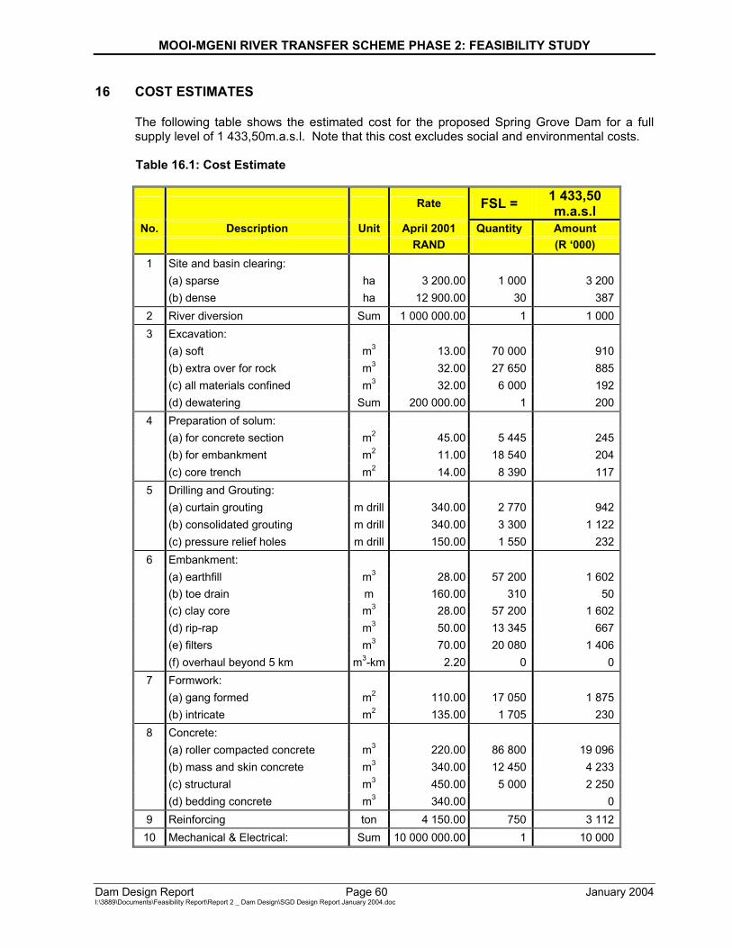
MOOI-MGENI RIVER TRANSFER SCHEME PHASE 2: FEASIBILITY STUDY
Dam Design Report Page 60 January 2004 I:\3889\Documents\Feasibility Report\Report 2 _ Dam Design\SGD Design Report January 2004.doc
16 COST ESTIMATES The following table shows the estimated cost for the proposed Spring Grove Dam for a full supply level of 1 433,50m.a.s.l. Note that this cost excludes social and environmental costs. Table 16.1: Cost Estimate
Rate FSL = 1 433,50 m.a.s.l
No. Description Unit April 2001 Quantity Amount RAND (R ‘000) 1 Site and basin clearing: (a) sparse ha 3 200.00 1 000 3 200 (b) dense ha 12 900.00 30 3872 River diversion Sum 1 000 000.00 1 1 0003 Excavation: (a) soft m3 13.00 70 000 910 (b) extra over for rock m3 32.00 27 650 885 (c) all materials confined m3 32.00 6 000 192 (d) dewatering Sum 200 000.00 1 2004 Preparation of solum: (a) for concrete section m2 45.00 5 445 245 (b) for embankment m2 11.00 18 540 204 (c) core trench m2 14.00 8 390 1175 Drilling and Grouting: (a) curtain grouting m drill 340.00 2 770 942 (b) consolidated grouting m drill 340.00 3 300 1 122 (c) pressure relief holes m drill 150.00 1 550 2326 Embankment: (a) earthfill m3 28.00 57 200 1 602 (b) toe drain m 160.00 310 50 (c) clay core m3 28.00 57 200 1 602 (d) rip-rap m3 50.00 13 345 667 (e) filters m3 70.00 20 080 1 406 (f) overhaul beyond 5 km m3-km 2.20 0 07 Formwork: (a) gang formed m2 110.00 17 050 1 875 (b) intricate m2 135.00 1 705 2308 Concrete: (a) roller compacted concrete m3 220.00 86 800 19 096 (b) mass and skin concrete m3 340.00 12 450 4 233 (c) structural m3 450.00 5 000 2 250 (d) bedding concrete m3 340.00 09 Reinforcing ton 4 150.00 750 3 11210 Mechanical & Electrical: Sum 10 000 000.00 1 10 000
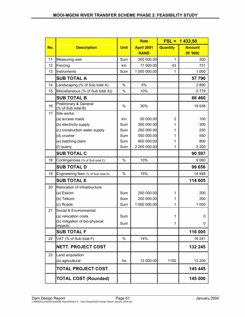
MOOI-MGENI RIVER TRANSFER SCHEME PHASE 2: FEASIBILITY STUDY
Dam Design Report Page 61 January 2004 I:\3889\Documents\Feasibility Report\Report 2 _ Dam Design\SGD Design Report January 2004.doc
Rate FSL = 1 433,50 No. Description Unit April 2001 Quantity Amount
RAND (R ‘000) 11 Measuring weir Sum 300 000.00 1 300 12 Fencing km 17 000.00 43 731 13 Instruments Sum 1 000 000.00 1 1 000
SUB TOTAL A 57 79014 Landscaping (% of Sub total A) % 5% 2 890 15 Miscellaneous (% of Sub total A)) % 10% 5 779
SUB TOTAL B 66 46016 Preliminary & General
(% of Sub total B) % 30% 19 938
17 Site works: (a) access roads km 50 000.00 2 100 (b) electricity supply Sum 300 000.00 1 300 (c) construction water supply Sum 250 000.00 1 250 (d) crusher Sum 550 000.00 1 550 (e) batching plant Sum 800 000.00 1 800
(f) quarry Sum 2 200 000.00 1 2 200
SUB TOTAL C 90 59718 Contingencies (% of Sub total C) % 10% 9 060
SUB TOTAL D 99 65619 Engineering fees (% of Sub total D) % 15% 14 948
SUB TOTAL E 114 60520 Relocation of infrastructure:
(a) Eskom Sum 200 000.00 1 200 (b) Telkom Sum 200 000.00 1 200 (c) Roads Sum 1 000 000.00 1 1 000
21 Social & Environmental: (a) relocation costs Sum 1 0
(b) mitigation of bio-physical impacts Sum 1 0
SUB TOTAL F 116 00522 VAT (% of Sub total F) % 14% 16 241
NETT. PROJECT COST 132 24523 Land acquisition:
(a) agricultural ha 12 000.00 1100 13 200
TOTAL PROJECT COST 145 445
TOTAL COST (Rounded) 145 000
MOOI-MGENI RIVER TRANSFER SCHEME PHASE 2: FEASIBILITY STUDY
Dam Design Report Page 62 January 2004 I:\3889\Documents\Feasibility Report\Report 2 _ Dam Design\SGD Design Report January 2004.doc
17 ENGINEERING ECONOMICS AND FINANCIAL ANALYSIS
A party independent from the Department of Water Affairs and Forestry will perform an Engineering Economics and Financial Analysis (refer to Supporting Report No.6). This analysis will commence as soon as Project Planning have received all the final feasibility study inputs from the various parties involved with this study. This feasibility design is a part of the inputs needed for the above-mentioned analysis.
MOOI-MGENI RIVER TRANSFER SCHEME PHASE 2: FEASIBILITY STUDY
Dam Design Report Page 63 January 2004 I:\3889\Documents\Feasibility Report\Report 2 _ Dam Design\SGD Design Report January 2004.doc
18 CONCLUSIONS AND RECOMMENDATIONS
Three layout options were considered for a full supply level of 1435,00m.a.s.l. The options were compared on the basis of their estimated costs. The study has found that a composite rollcrete gravity / embankment dam to be the optimal solution for the proposed dam site. (Note that the FSL was changed to 1433,50m.a.s.l at a late stage of the feasibility design. These and other calculations have not been redone for the revised FSL and should be taken into account during the final design stage.) The proposed Spring Grove Dam will have an impact on Main Road 27, which links Nottingham Road and Himeville/Sani Pass. The road crosses a tributary of the Mooi River upstream of the proposed dam site by means of one 3,0 × 3,0m box culvert. Only a full supply level of less than 1432,00m.a.s.l. will have no significant impact on the culvert. It was concluded that the road will have to be relocated or raised should the full supply level of the proposed dam stay at 1433,50m.a.s.l. The Inchbrakie Waterfall is located in the Mooi River upstream of the proposed dam site. It was concluded that the full supply level of the dam would have to be significantly lowered if the impact thereof is to be minimised on this waterfall, which in turn can result in the proposed dam being uneconomical. The design needs to be redone at the final design stage. The feasibility design cannot be guaranteed for final construction purposes, and it should only serve as a guideline for the future design team.
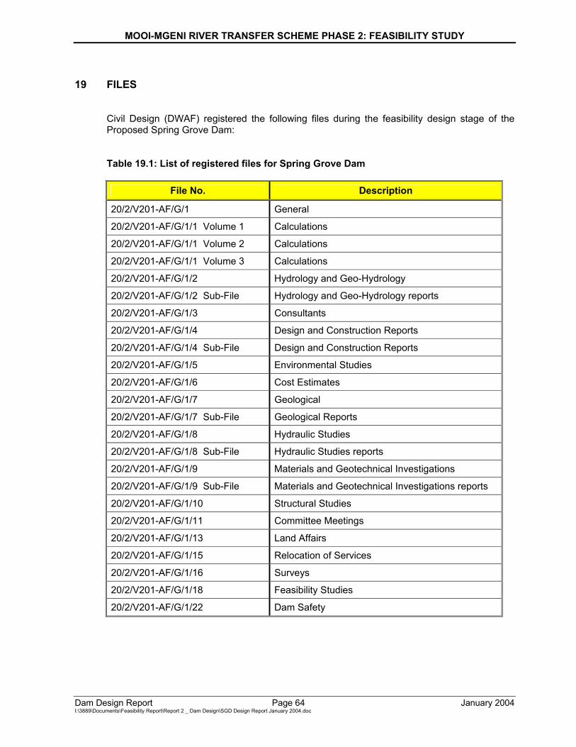
MOOI-MGENI RIVER TRANSFER SCHEME PHASE 2: FEASIBILITY STUDY
Dam Design Report Page 64 January 2004 I:\3889\Documents\Feasibility Report\Report 2 _ Dam Design\SGD Design Report January 2004.doc
19 FILES
Civil Design (DWAF) registered the following files during the feasibility design stage of the Proposed Spring Grove Dam: Table 19.1: List of registered files for Spring Grove Dam
File No. Description
20/2/V201-AF/G/1 General
20/2/V201-AF/G/1/1 Volume 1 Calculations
20/2/V201-AF/G/1/1 Volume 2 Calculations
20/2/V201-AF/G/1/1 Volume 3 Calculations
20/2/V201-AF/G/1/2 Hydrology and Geo-Hydrology
20/2/V201-AF/G/1/2 Sub-File Hydrology and Geo-Hydrology reports
20/2/V201-AF/G/1/3 Consultants
20/2/V201-AF/G/1/4 Design and Construction Reports
20/2/V201-AF/G/1/4 Sub-File Design and Construction Reports
20/2/V201-AF/G/1/5 Environmental Studies
20/2/V201-AF/G/1/6 Cost Estimates
20/2/V201-AF/G/1/7 Geological
20/2/V201-AF/G/1/7 Sub-File Geological Reports
20/2/V201-AF/G/1/8 Hydraulic Studies
20/2/V201-AF/G/1/8 Sub-File Hydraulic Studies reports
20/2/V201-AF/G/1/9 Materials and Geotechnical Investigations
20/2/V201-AF/G/1/9 Sub-File Materials and Geotechnical Investigations reports
20/2/V201-AF/G/1/10 Structural Studies
20/2/V201-AF/G/1/11 Committee Meetings
20/2/V201-AF/G/1/13 Land Affairs
20/2/V201-AF/G/1/15 Relocation of Services
20/2/V201-AF/G/1/16 Surveys
20/2/V201-AF/G/1/18 Feasibility Studies
20/2/V201-AF/G/1/22 Dam Safety
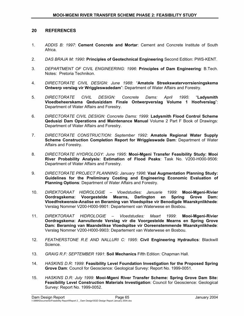
MOOI-MGENI RIVER TRANSFER SCHEME PHASE 2: FEASIBILITY STUDY
Dam Design Report Page 65 January 2004 I:\3889\Documents\Feasibility Report\Report 2 _ Dam Design\SGD Design Report January 2004.doc
20 REFERENCES 1. ADDIS B: 1997: Cement Concrete and Mortar: Cement and Concrete Institute of South
Africa. 2. DAS BRAJA M: 1990: Principles of Geotechnical Engineering Second Edition: PWS-KENT. 3. DEPARTMENT OF CIVIL ENGINEERING: 1996: Principles of Dam Engineering: B.Tech.
Notes: Pretoria Technikon. 4. DIRECTORATE CIVIL DESIGN: June 1988: “Amatole Streekswatervorrsieningskema
Ontwerp verslag vir Wriggleswadedam”: Department of Water Affairs and Forestry. 5. DIRECTORATE CIVIL DESIGN: Concrete Dams: April 1995: “Ladysmith
Vloedbeheerskama Qedusizidam Finale Ontwerpverslag Volume 1 Hoofverslag”: Department of Water Affairs and Forestry.
6. DIRECTORATE CIVIL DESIGN: Concrete Dams: 1999: Ladysmith Flood Control Scheme
Qedusizi Dam Operations and Maintenance Manual Volume 2 Part F Book of Drawings: Department of Water Affairs and Forestry.
7. DIRECTORATE CONSTRUCTION: September 1992: Amatole Regional Water Supply
Scheme Construction Completion Report for Wriggleswade Dam: Department of Water Affairs and Forestry.
8. DIRECTORATE HYDROLOGY: June 1995: Mooi-Mgeni Transfer Feasibility Study: Mooi
River Probability Analysis: Estimation of Flood Peaks: Task No. V200-H000-9506: Department of Water Affairs and Forestry.
9. DIRECTORATE PROJECT PLANNING: January 1996: Vaal Augmentation Planning Study:
Guidelines for the Preliminary Costing and Engineering Economic Evaluation of Planning Options: Department of Water Affairs and Forestry.
10. DIREKTORAAT HIDROLOGIE – Vloedstudies: Januarie 1999: Mooi-Mgeni-Rivier
Oordragskema: Voorgestelde Mearns, Darlington en Spring Grove Dam: Vloedfrekwensie-Analise en Beraming van Vloedspitse vir Benodigde Waarskynlikhede: Verslag Nommer V200-H000-9901: Departement van Waterwese en Bosbou.
11. DIREKTORAAT HIDROLOGIE – Vloedstudies: Maart 1999: Mooi-Mgeni-Rivier
Oordragskema: Aanvullende Verslag vir die Voorgestelde Mearns en Spring Grove Dam: Beraming van Maandelikse Vloedspitse vir Ooreenstemmende Waarskynlikhede: Verslag Nommer V200-H000-9903: Departement van Waterwese en Bosbou.
12. FEATHERSTONE R.E AND NALLURI C: 1995: Civil Engineering Hydraulics: Blackwill
Science. 13. GRAIG R.F: SEPTEMBER 1991: Soil Mechanics Fifth Edition: Chapman Hall. 14. HASKINS D.R: 1999: Feasibility Level Foundation Investigation for the Proposed Spring
Grove Dam: Council for Geoscience: Geological Survey: Report No. 1999-0051. 15. HASKINS D.R: July 1999: Mooi-Mgeni River Transfer Scheme: Spring Grove Dam Site:
Feasibility Level Construction Materials Investigation: Council for Geoscience: Geological Survey: Report No. 1999-0052.
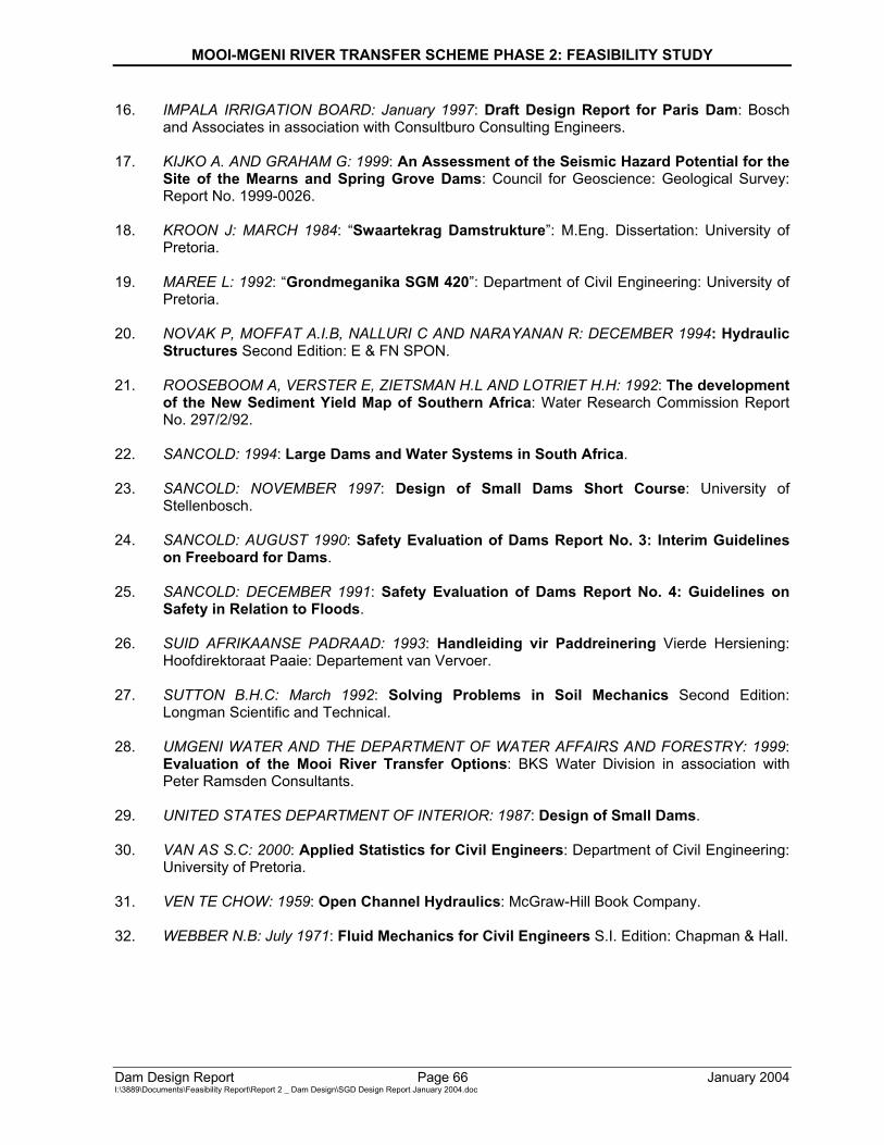
MOOI-MGENI RIVER TRANSFER SCHEME PHASE 2: FEASIBILITY STUDY
Dam Design Report Page 66 January 2004 I:\3889\Documents\Feasibility Report\Report 2 _ Dam Design\SGD Design Report January 2004.doc
16. IMPALA IRRIGATION BOARD: January 1997: Draft Design Report for Paris Dam: Bosch and Associates in association with Consultburo Consulting Engineers.
17. KIJKO A. AND GRAHAM G: 1999: An Assessment of the Seismic Hazard Potential for the
Site of the Mearns and Spring Grove Dams: Council for Geoscience: Geological Survey: Report No. 1999-0026.
18. KROON J: MARCH 1984: “Swaartekrag Damstrukture”: M.Eng. Dissertation: University of
Pretoria. 19. MAREE L: 1992: “Grondmeganika SGM 420”: Department of Civil Engineering: University of
Pretoria. 20. NOVAK P, MOFFAT A.I.B, NALLURI C AND NARAYANAN R: DECEMBER 1994: Hydraulic
Structures Second Edition: E & FN SPON. 21. ROOSEBOOM A, VERSTER E, ZIETSMAN H.L AND LOTRIET H.H: 1992: The development
of the New Sediment Yield Map of Southern Africa: Water Research Commission Report No. 297/2/92.
22. SANCOLD: 1994: Large Dams and Water Systems in South Africa. 23. SANCOLD: NOVEMBER 1997: Design of Small Dams Short Course: University of
Stellenbosch. 24. SANCOLD: AUGUST 1990: Safety Evaluation of Dams Report No. 3: Interim Guidelines
on Freeboard for Dams. 25. SANCOLD: DECEMBER 1991: Safety Evaluation of Dams Report No. 4: Guidelines on
Safety in Relation to Floods. 26. SUID AFRIKAANSE PADRAAD: 1993: Handleiding vir Paddreinering Vierde Hersiening:
Hoofdirektoraat Paaie: Departement van Vervoer. 27. SUTTON B.H.C: March 1992: Solving Problems in Soil Mechanics Second Edition:
Longman Scientific and Technical. 28. UMGENI WATER AND THE DEPARTMENT OF WATER AFFAIRS AND FORESTRY: 1999:
Evaluation of the Mooi River Transfer Options: BKS Water Division in association with Peter Ramsden Consultants.
29. UNITED STATES DEPARTMENT OF INTERIOR: 1987: Design of Small Dams. 30. VAN AS S.C: 2000: Applied Statistics for Civil Engineers: Department of Civil Engineering:
University of Pretoria. 31. VEN TE CHOW: 1959: Open Channel Hydraulics: McGraw-Hill Book Company. 32. WEBBER N.B: July 1971: Fluid Mechanics for Civil Engineers S.I. Edition: Chapman & Hall.
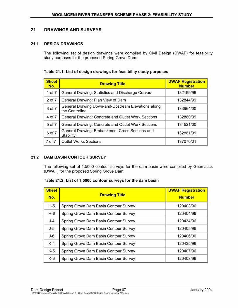
MOOI-MGENI RIVER TRANSFER SCHEME PHASE 2: FEASIBILITY STUDY
Dam Design Report Page 67 January 2004 I:\3889\Documents\Feasibility Report\Report 2 _ Dam Design\SGD Design Report January 2004.doc
21 DRAWINGS AND SURVEYS 21.1 DESIGN DRAWINGS
The following set of design drawings were compiled by Civil Design (DWAF) for feasibility study purposes for the proposed Spring Grove Dam:
Table 21.1: List of design drawings for feasibility study purposes Sheet
No. Drawing Title DWAF Registration Number
1 of 7 General Drawing: Statistics and Discharge Curves 132199/99
2 of 7 General Drawing: Plan View of Dam 132844/99
3 of 7 General Drawing Down-and-Upstream Elevations along the Centreline 133964/00
4 of 7 General Drawing: Concrete and Outlet Work Sections 132880/99
5 of 7 General Drawing: Concrete and Outlet Work Sections 134521/00
6 of 7 General Drawing: Embankment Cross Sections and Stability 132881/99
7 of 7 Outlet Works Sections 137070/01 21.2 DAM BASIN CONTOUR SURVEY
The following set of 1:5000 contour surveys for the dam basin were compiled by Geomatics (DWAF) for the proposed Spring Grove Dam: Table 21.2: List of 1:5000 contour surveys for the dam basin Sheet
No. Drawing Title DWAF Registration
Number
H-5 Spring Grove Dam Basin Contour Survey 120403/96
H-6 Spring Grove Dam Basin Contour Survey 120404/96
J-4 Spring Grove Dam Basin Contour Survey 120434/96
J-5 Spring Grove Dam Basin Contour Survey 120405/96
J-6 Spring Grove Dam Basin Contour Survey 120406/96
K-4 Spring Grove Dam Basin Contour Survey 120435/96
K-5 Spring Grove Dam Basin Contour Survey 120407/96
K-6 Spring Grove Dam Basin Contour Survey 120408/96
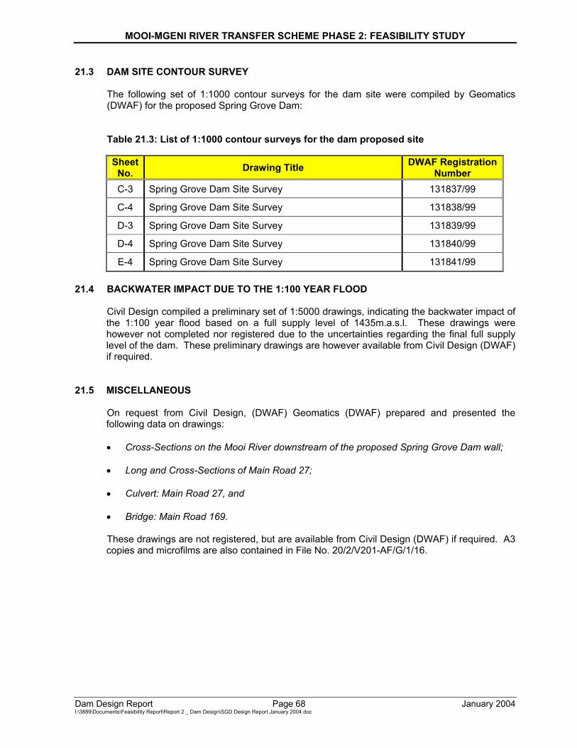
MOOI-MGENI RIVER TRANSFER SCHEME PHASE 2: FEASIBILITY STUDY
Dam Design Report Page 68 January 2004 I:\3889\Documents\Feasibility Report\Report 2 _ Dam Design\SGD Design Report January 2004.doc
21.3 DAM SITE CONTOUR SURVEY
The following set of 1:1000 contour surveys for the dam site were compiled by Geomatics (DWAF) for the proposed Spring Grove Dam: Table 21.3: List of 1:1000 contour surveys for the dam proposed site
Sheet
No. Drawing Title DWAF Registration Number
C-3 Spring Grove Dam Site Survey 131837/99
C-4 Spring Grove Dam Site Survey 131838/99
D-3 Spring Grove Dam Site Survey 131839/99
D-4 Spring Grove Dam Site Survey 131840/99
E-4 Spring Grove Dam Site Survey 131841/99 21.4 BACKWATER IMPACT DUE TO THE 1:100 YEAR FLOOD
Civil Design compiled a preliminary set of 1:5000 drawings, indicating the backwater impact of the 1:100 year flood based on a full supply level of 1435m.a.s.l. These drawings were however not completed nor registered due to the uncertainties regarding the final full supply level of the dam. These preliminary drawings are however available from Civil Design (DWAF) if required.
21.5 MISCELLANEOUS On request from Civil Design, (DWAF) Geomatics (DWAF) prepared and presented the following data on drawings: • Cross-Sections on the Mooi River downstream of the proposed Spring Grove Dam wall; • Long and Cross-Sections of Main Road 27; • Culvert: Main Road 27, and • Bridge: Main Road 169. These drawings are not registered, but are available from Civil Design (DWAF) if required. A3 copies and microfilms are also contained in File No. 20/2/V201-AF/G/1/16.
MOOI-MGENI RIVER TRANSFER SCHEME PHASE 2: FEASIBILITY STUDY
Dam Design Report January 2004 I:\3889\Documents\Feasibility Report\Report 2 _ Dam Design\SGD Design Report January 2004.doc
ANNEXURES A. DAM STATISTICS A-1 A.1 Locality A.2 Structural information A.3 Reservoir information A.4 Hydrology A.5 Outlet works A.6 Area-capacity tables B. RELEVANT MAPS B-1 B.1 Locality B.2 Dam basin contour survey B.3 Dam site contour survey C. RELEVANT DRAWINGS C-1 C.1 Design drawings C.2 Miscellaneous D. REQUEST FROM PROJECT PLANNING (TERMS OF REFERENCE) D-1 E. CONCRETE SPECIFICATIONS E-1 F. CONSTRUCTION PROGRAMME F-1 G. COMMENTS FROM HYDROLOGY REGARDING THE EXTREME G-1 FLOODING CONDITIONS H. COMMENTS BY CIVIL DESIGN ON FEASIBILITY LEVEL DESIGN H-1
MOOI-MGENI RIVER TRANSFER SCHEME PHASE 2: FEASIBILITY STUDY
Dam Design Report January 2004 I:\3889\Documents\Feasibility Report\Report 2 _ Dam Design\SGD Design Report January 2004.doc
A. DAM STATISTICS
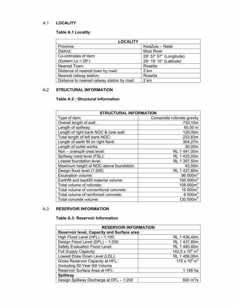
A.1 LOCALITY Table A.1 Locality
LOCALITY Province: KwaZulu – Natal District: Mooi River Co-ordinates of dam: (System Lo = 29°)
29° 57’ 57’’ (Longitude) 29° 19’ 10’’ (Latitude)
Nearest Town: Rosetta Distance of nearest town by road: 2 km Nearest railway station: Rosetta Distance to nearest railway station by road: 2 km
A.2 STRUCTURAL INFORMATION Table A.2 : Structural Information
STRUCTURAL INFORMATION Type of dam: Composite rollcrete gravityOverall length of wall: 733,10mLength of spillway: 60,00 mLength of right bank NOC & core wall: 120,00mTotal length of left bank NOC: 233,83mLength of earth fill on right flank: 304,27mLength of outlet works: 30,00mNon – overspill crest level: RL 1 441,00mSpillway crest level (FSL): RL 1 433,50mLowest foundation level: RL 1 397,50mMaximum height of NOC above foundation: 43,50mDesign flood level (1:200) RL 1 437,80mExcavation volume: 96 000m3
Earthfill and backfill material volume: 195 000m3
Total volume of rollcrete: 108 000m3
Total volume of conventional concrete: 16 000m3
Total volume of reinforced concrete: 6 500m3
Total concrete volume: 130 500m3
A.3 RESERVOIR INFORMATION Table A.3: Reservoir Information
RESERVOIR INFORMATION Reservoir level, Capacity and Surface area: High Flood Level (HFL) – 1:100: RL 1 436,40mDesign Flood Level (DFL) – 1:200: RL 1 437,80mSafety Evaluation Flood Level: RL 1 440,40mFull Supply Capacity: 142,5 x 10⁶ m3
Lowest Draw Down Level (LDL): RL 1 406,00mGross Reservoir Capacity at HFL: (Including 50 Year Silt Volume
170 x 106 m3
Reservoir Surface Area at HFL: 1 146 haSpillway Design Spillway Discharge at DFL – 1:200 600 m3/s
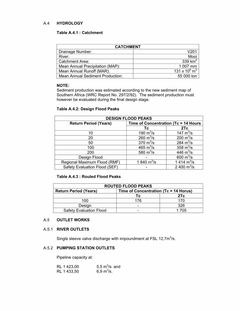
A.4 HYDROLOGY Table A.4.1 : Catchment
CATCHMENT Drainage Number: V201River: MooiCatchment Area: 339 km2
Mean Annual Precipitation (MAP): 1 007 mmMean Annual Runoff (MAR): 131 x 106 m3
Mean Annual Sediment Production: 55 000 ton NOTE:
Sediment production was estimated according to the new sediment map of Southern Africa (WRC Report No. 297/2/92). The sediment production must however be evaluated during the final design stage. Table A.4.2: Design Flood Peaks
DESIGN FLOOD PEAKS Time of Concentration (Tc = 14 HoursReturn Period (Years)
Tc 2Tc 10 190 m3/s 147 m3/s 20 260 m3/s 200 m3/s 50 370 m3/s 284 m3/s
100 465 m3/s 358 m3/s 200 580 m3/s 446 m3/s
Design Flood - 600 m3/s Regional Maximum Flood (RMF) 1 840 m3/s 1 414 m3/s Safety Evaluation Flood (SEF) - 2 400 m3/s
Table A.4.3 : Routed Flood Peaks
ROUTED FLOOD PEAKS Return Period (Years) Time of Concentration (Tc = 14 Horus) Tc 2Tc
100 176 170 Design - 326
Safety Evaluation Flood - 1 705 A.5 OUTLET WORKS A.5.1 RIVER OUTLETS Single sleeve valve discharge with impoundment at FSL 12,7m3/s. A.5.2 PUMPING STATION OUTLETS Pipeline capacity at: RL 1 423,00 5,5 m3/s: and RL 1 433,50 6,9 m3/s.
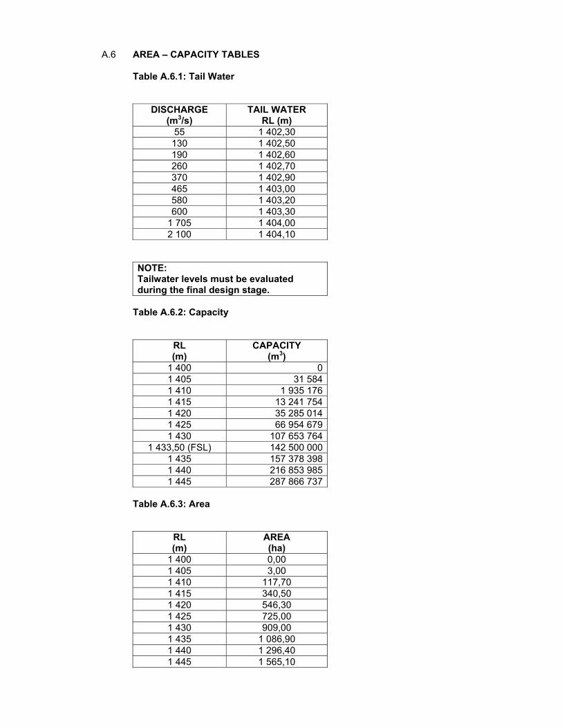
A.6 AREA – CAPACITY TABLES Table A.6.1: Tail Water
DISCHARGE (m3/s)
TAIL WATER RL (m)
55 1 402,30 130 1 402,50 190 1 402,60 260 1 402,70 370 1 402,90 465 1 403,00 580 1 403,20 600 1 403,30
1 705 1 404,00 2 100 1 404,10
NOTE: Tailwater levels must be evaluated during the final design stage.
Table A.6.2: Capacity
RL (m)
CAPACITY (m3)
1 400 01 405 31 5841 410 1 935 1761 415 13 241 7541 420 35 285 0141 425 66 954 6791 430 107 653 764
1 433,50 (FSL) 142 500 0001 435 157 378 3981 440 216 853 9851 445 287 866 737
Table A.6.3: Area
RL (m)
AREA (ha)
1 400 0,00 1 405 3,00 1 410 117,70 1 415 340,50 1 420 546,30 1 425 725,00 1 430 909,00 1 435 1 086,90 1 440 1 296,40 1 445 1 565,10
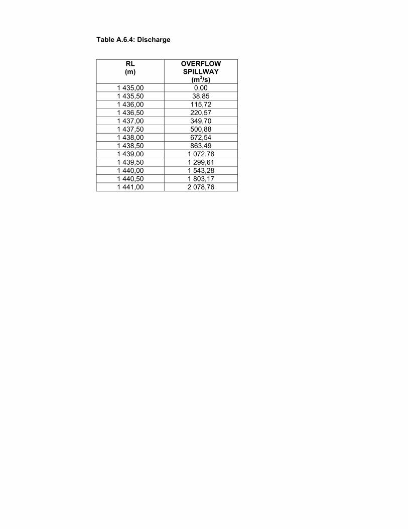
Table A.6.4: Discharge
RL (m)
OVERFLOW SPILLWAY
(m3/s) 1 435,00 0,00 1 435,50 38,85 1 436,00 115,72 1 436,50 220,57 1 437,00 349,70 1 437,50 500,88 1 438,00 672,54 1 438,50 863,49 1 439,00 1 072,78 1 439,50 1 299,61 1 440,00 1 543,28 1 440,50 1 803,17 1 441,00 2 078,76

MOOI-MGENI RIVER TRANSFER SCHEME PHASE 2: FEASIBILITY STUDY
Dam Design Report January 2004 I:\3889\Documents\Feasibility Report\Report 2 _ Dam Design\SGD Design Report January 2004.doc
B. RELEVANT MAPS

MOOI-MGENI RIVER TRANSFER SCHEME PHASE 2: FEASIBILITY STUDY
Dam Design Report January 2004 I:\3889\Documents\Feasibility Report\Report 2 _ Dam Design\SGD Design Report January 2004.doc
B.1 Locality
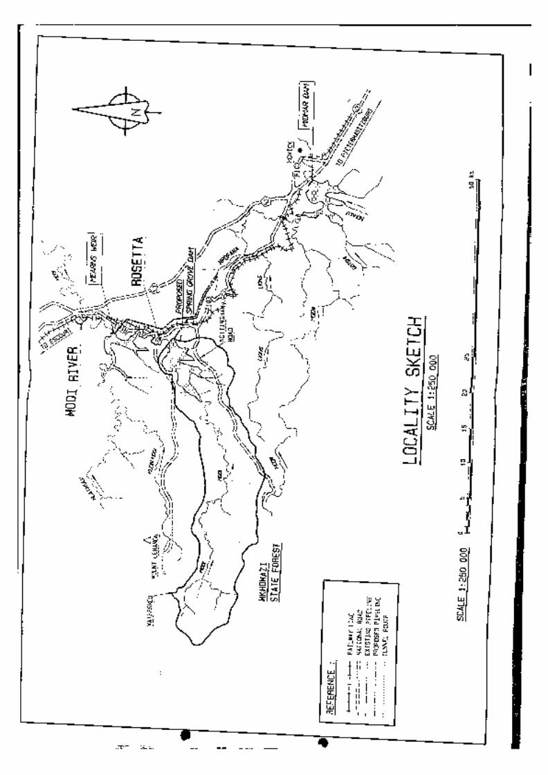
MOOI-MGENI RIVER TRANSFER SCHEME PHASE 2: FEASIBILITY STUDY
Dam Design Report January 2004 I:\3889\Documents\Feasibility Report\Report 2 _ Dam Design\SGD Design Report January 2004.doc
B.2 Dam Basin Contour Survey
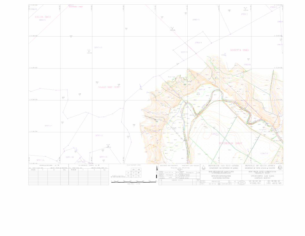
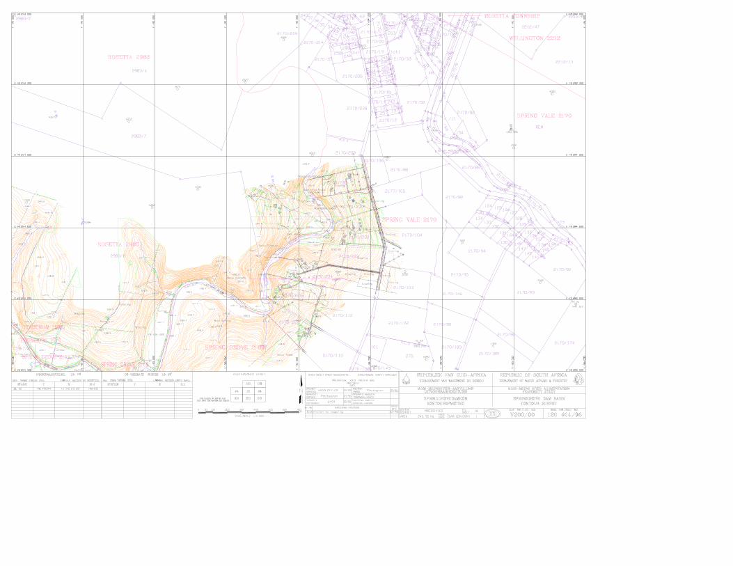
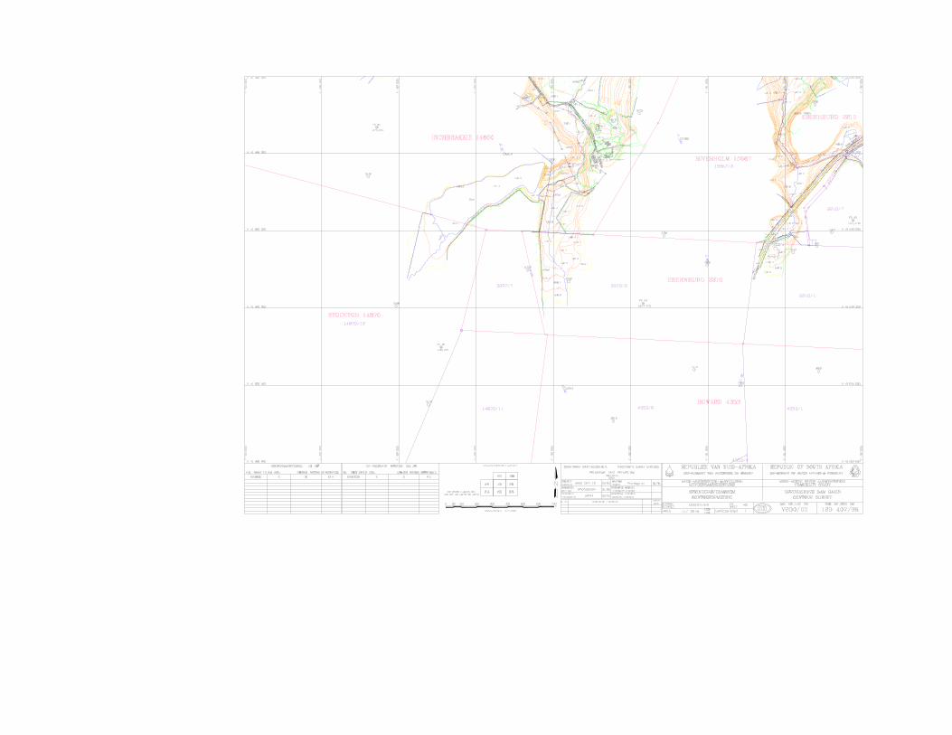
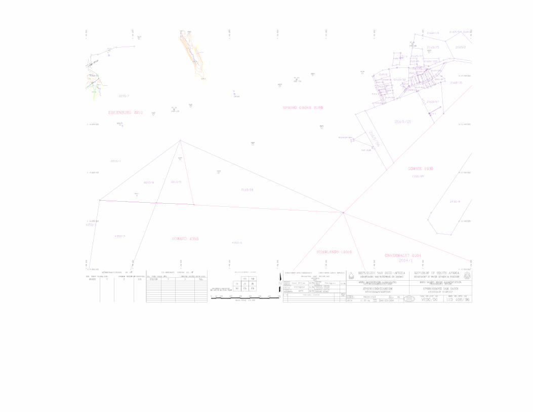
MOOI-MGENI RIVER TRANSFER SCHEME PHASE 2: FEASIBILITY STUDY
Dam Design Report January 2004 I:\3889\Documents\Feasibility Report\Report 2 _ Dam Design\SGD Design Report January 2004.doc
B.3 Dam Site Contour Survey
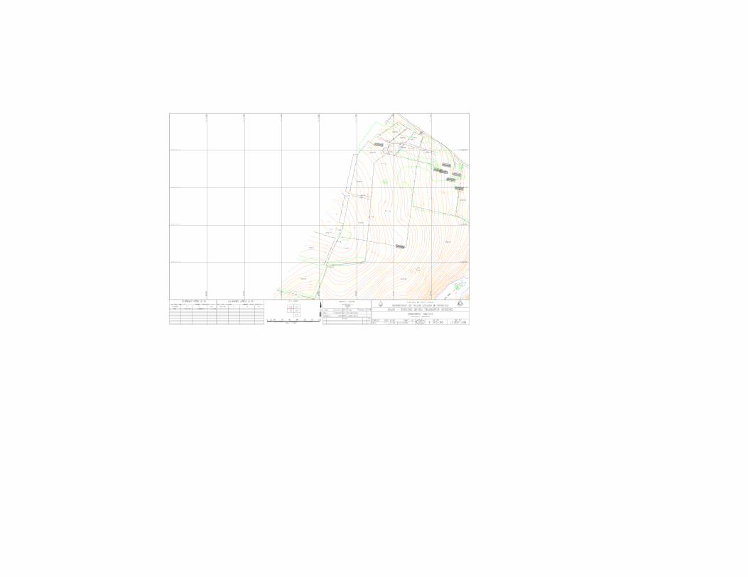

MOOI-MGENI RIVER TRANSFER SCHEME PHASE 2: FEASIBILITY STUDY
Dam Design Report January 2004 I:\3889\Documents\Feasibility Report\Report 2 _ Dam Design\SGD Design Report January 2004.doc
C. RELEVANT DRAWINGS

MOOI-MGENI RIVER TRANSFER SCHEME PHASE 2: FEASIBILITY STUDY
Dam Design Report January 2004 I:\3889\Documents\Feasibility Report\Report 2 _ Dam Design\SGD Design Report January 2004.doc
C.1 Design Drawings
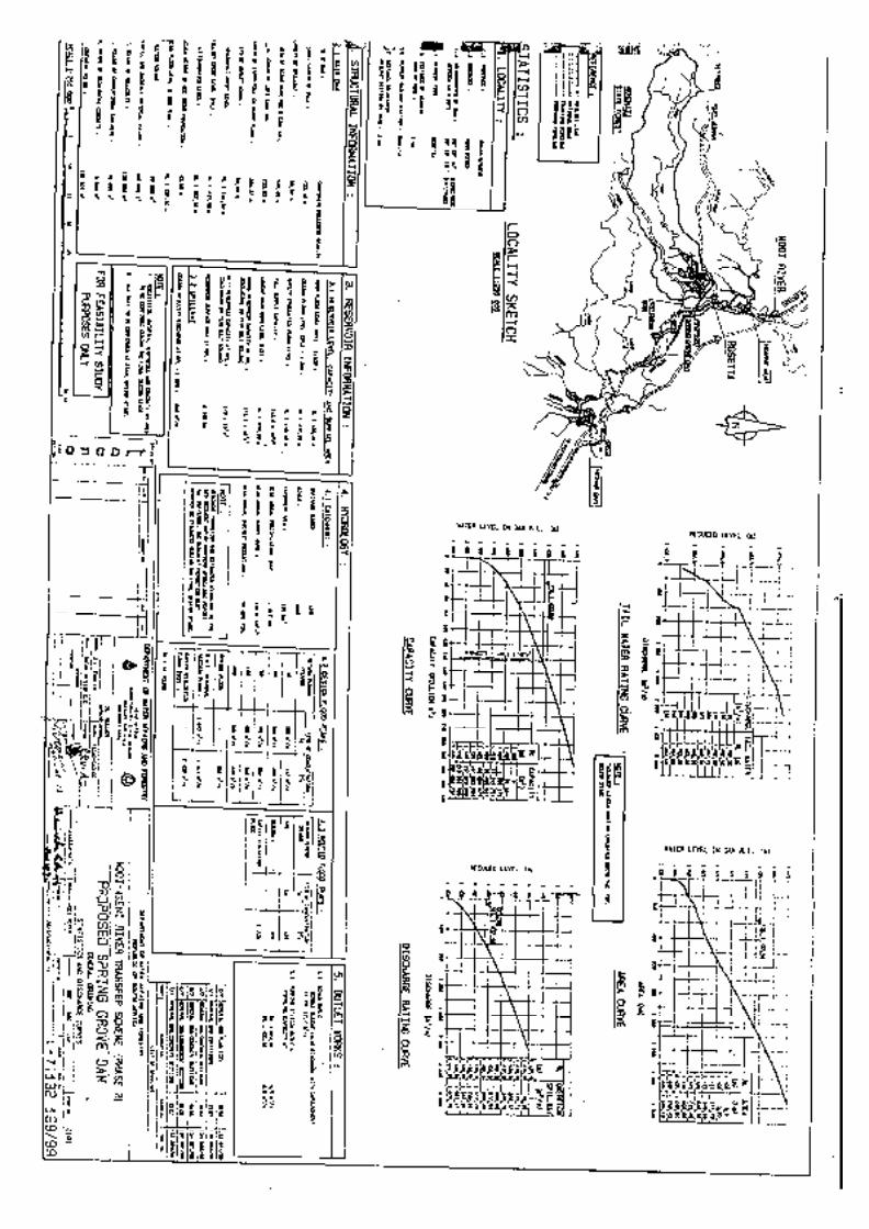
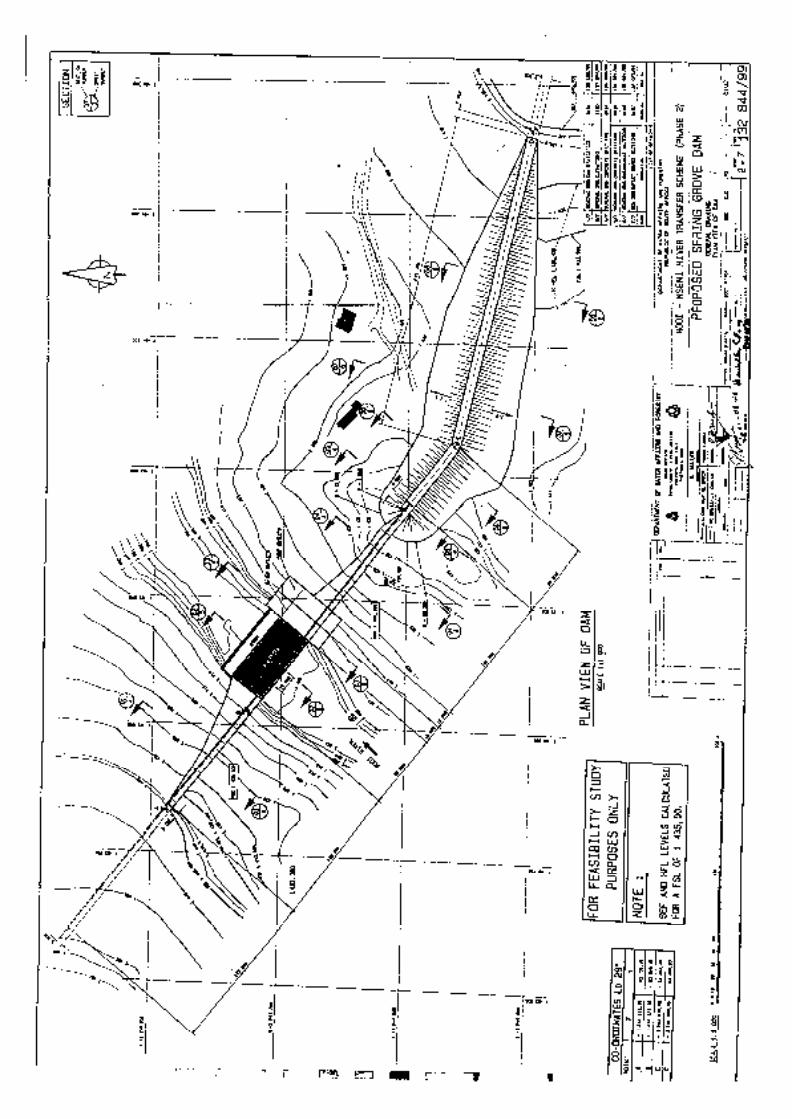
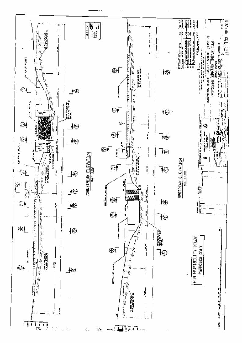
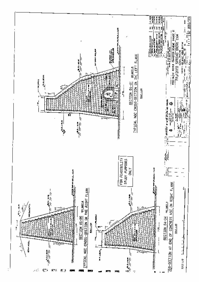
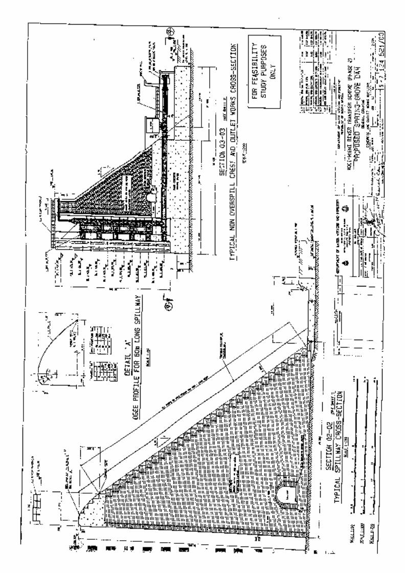
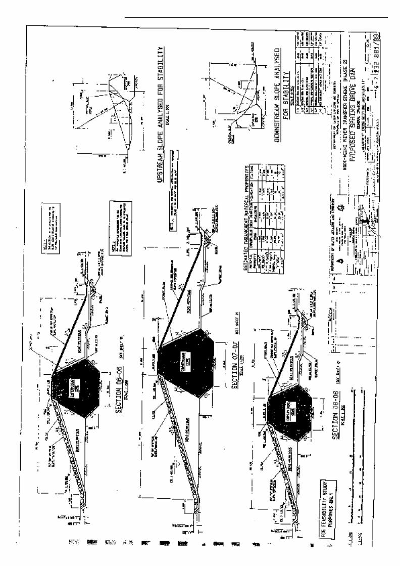
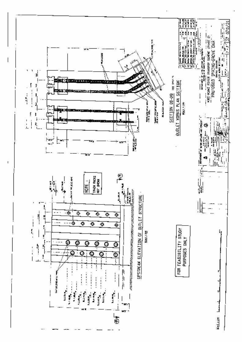
MOOI-MGENI RIVER TRANSFER SCHEME PHASE 2: FEASIBILITY STUDY
Dam Design Report January 2004 I:\3889\Documents\Feasibility Report\Report 2 _ Dam Design\SGD Design Report January 2004.doc
C.2 Miscellaneous
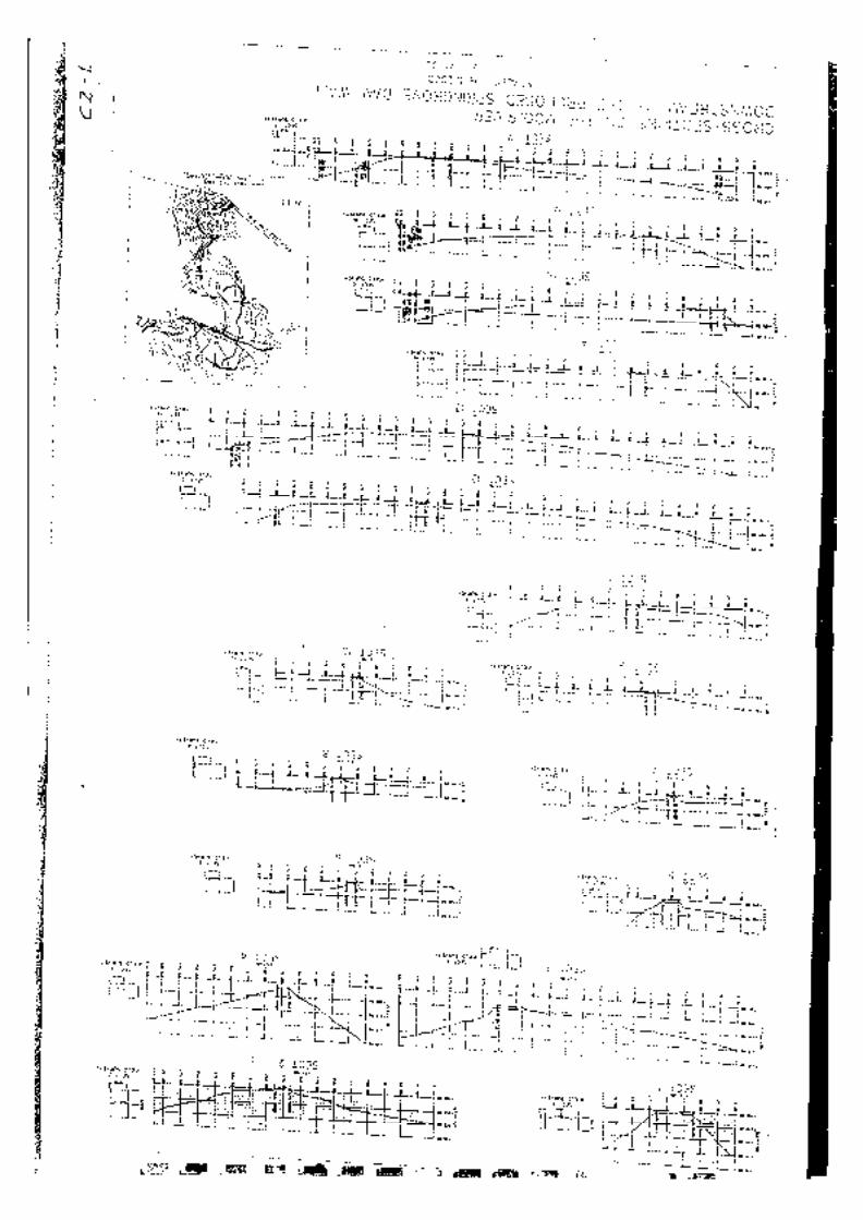
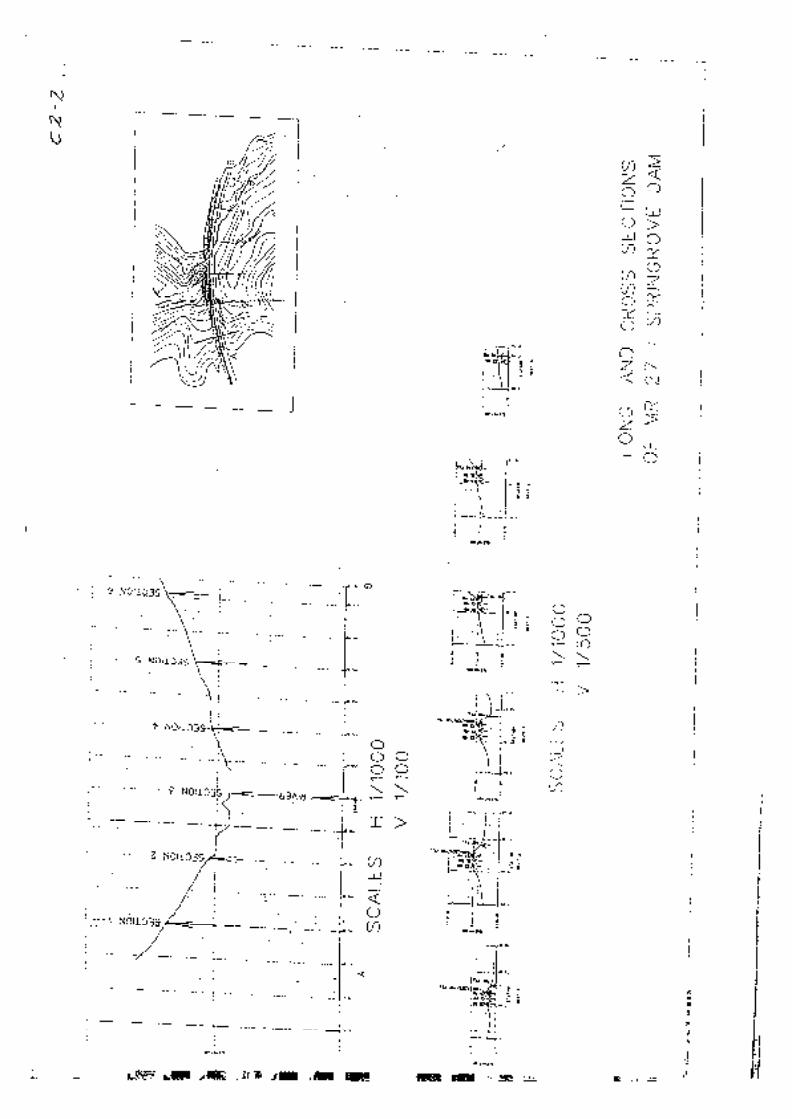
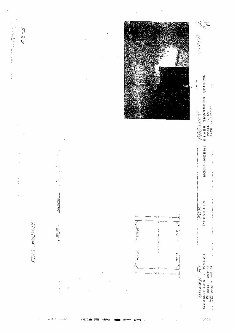
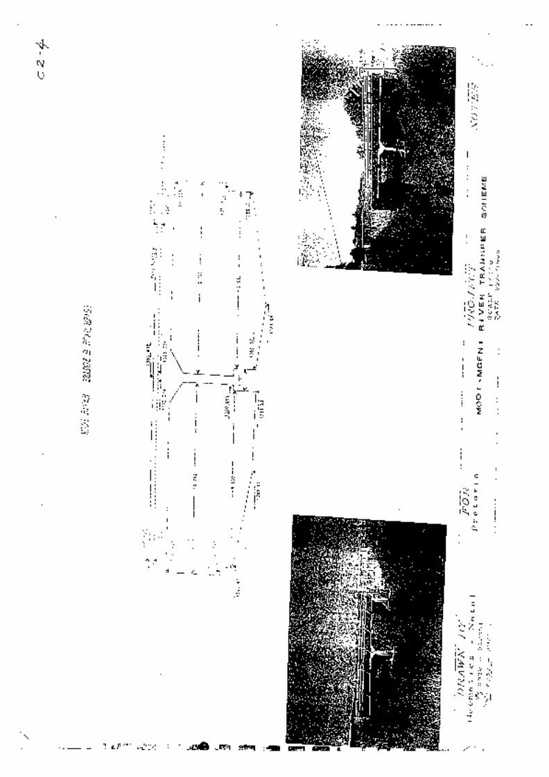
MOOI-MGENI RIVER TRANSFER SCHEME PHASE 2: FEASIBILITY STUDY
Dam Design Report January 2004 I:\3889\Documents\Feasibility Report\Report 2 _ Dam Design\SGD Design Report January 2004.doc
D. REQUEST FROM PROJECT PLANNING TERMS OF REFERENCE
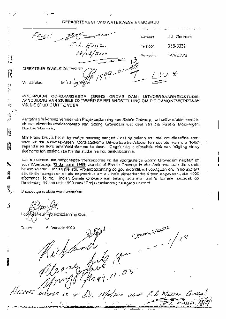
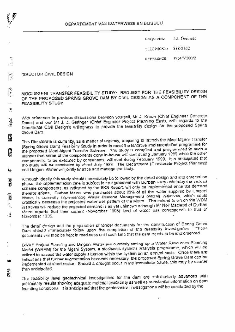
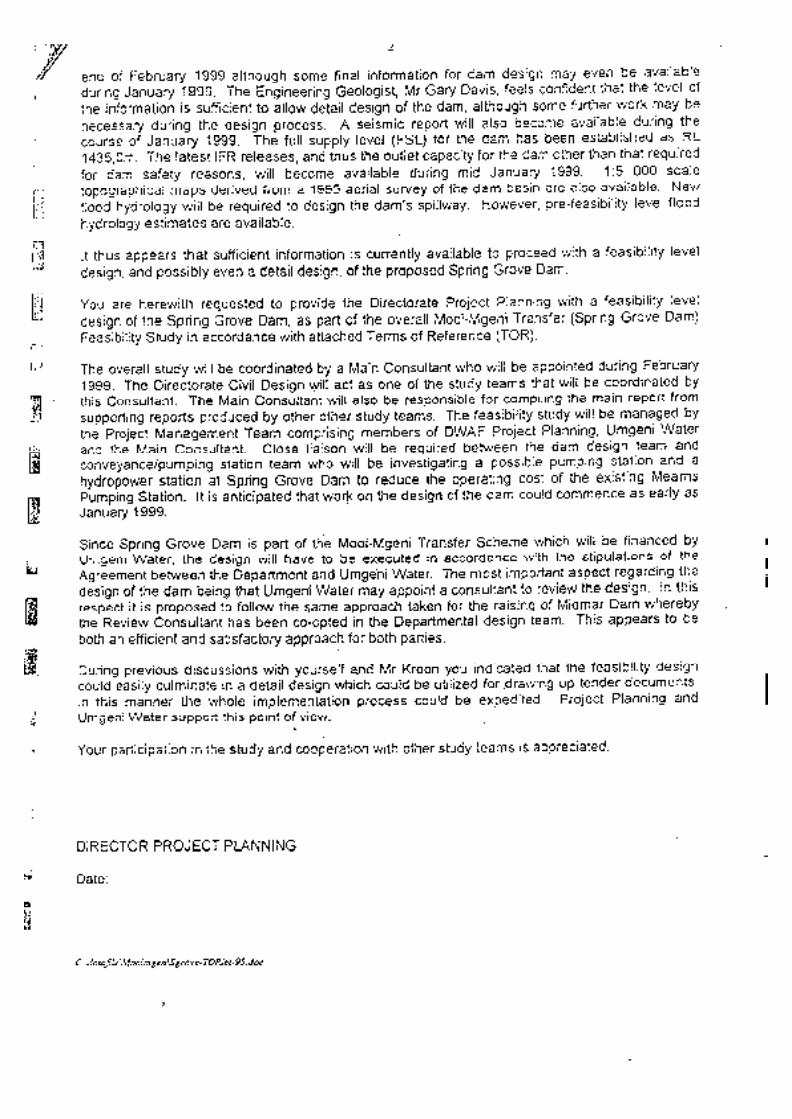
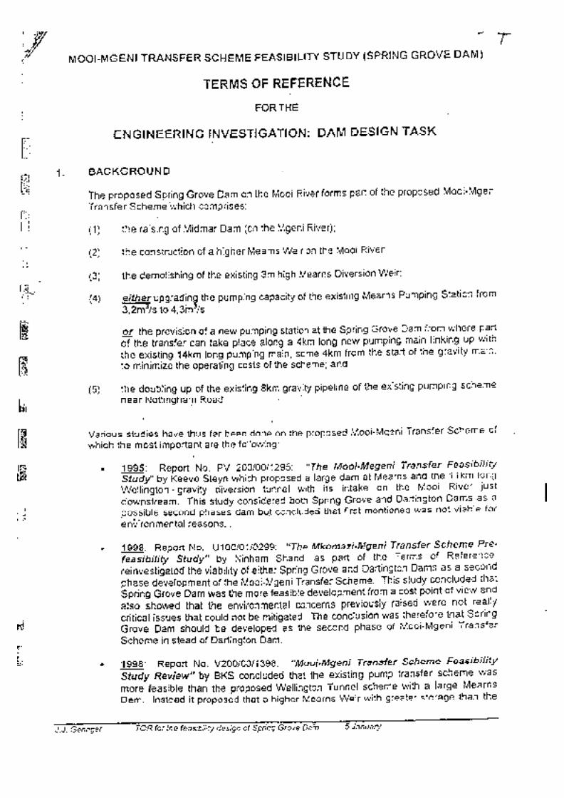
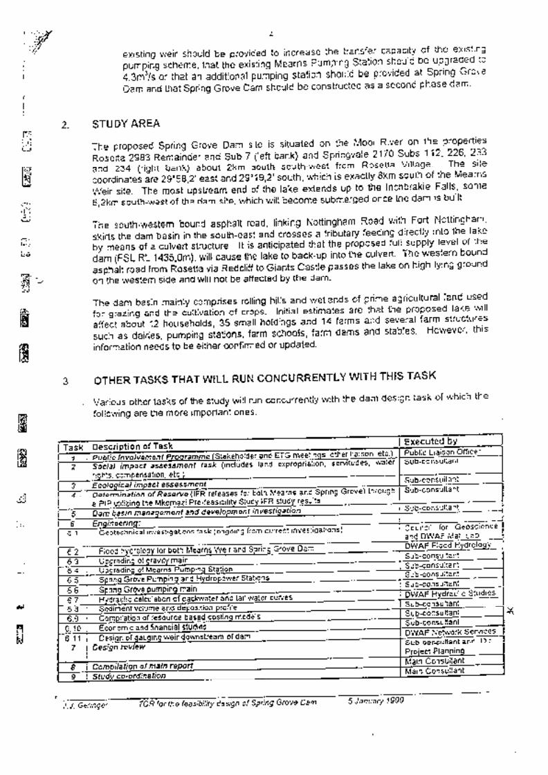
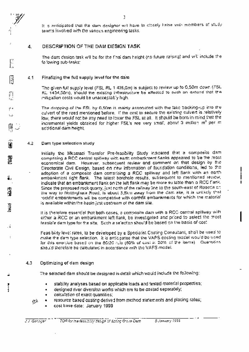
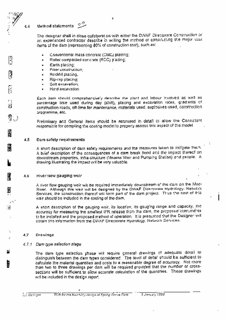
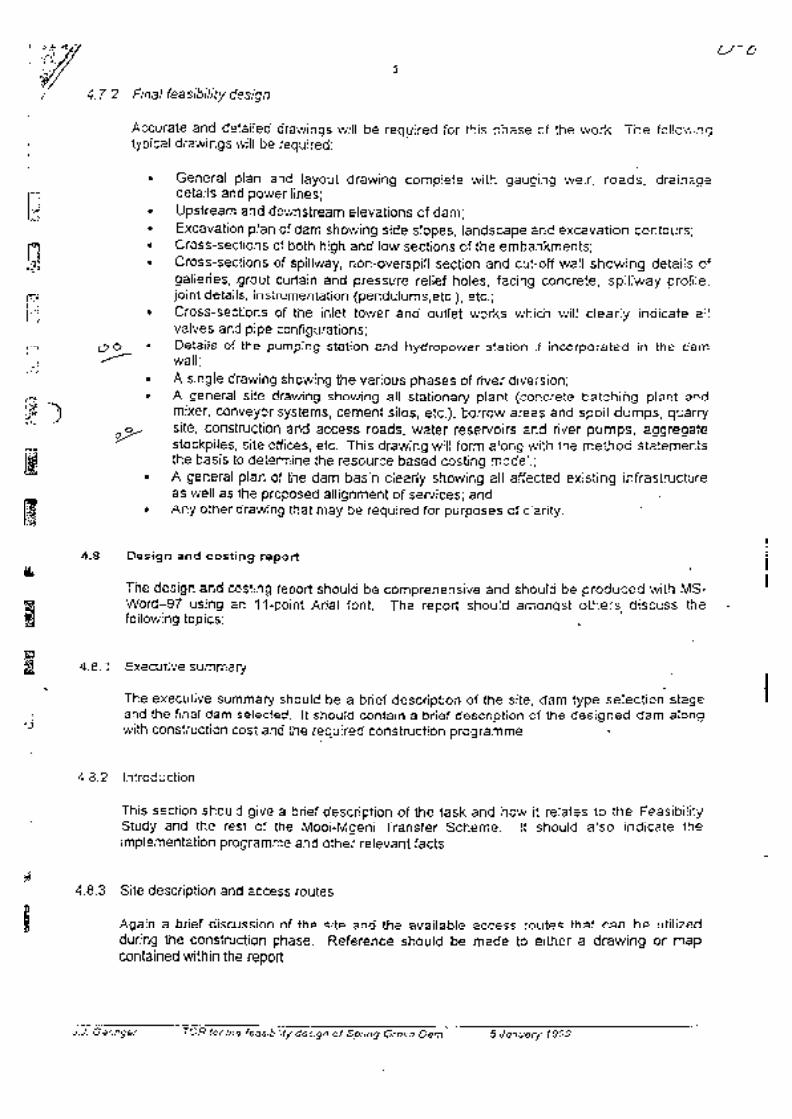
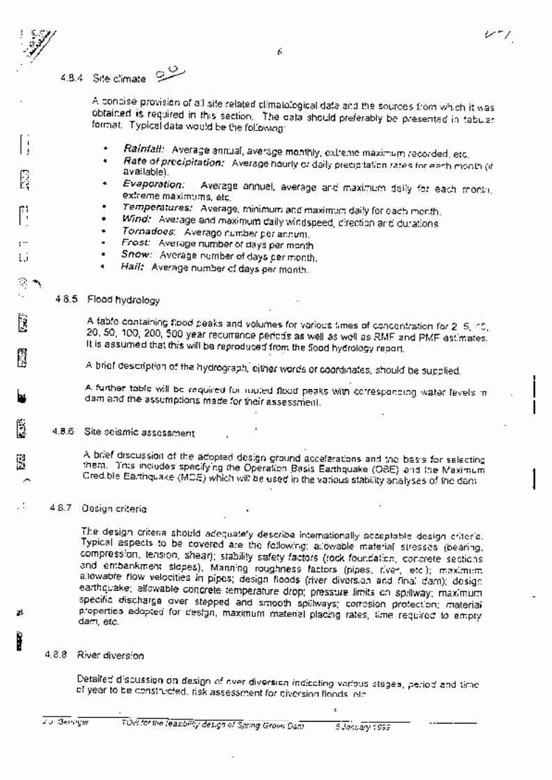
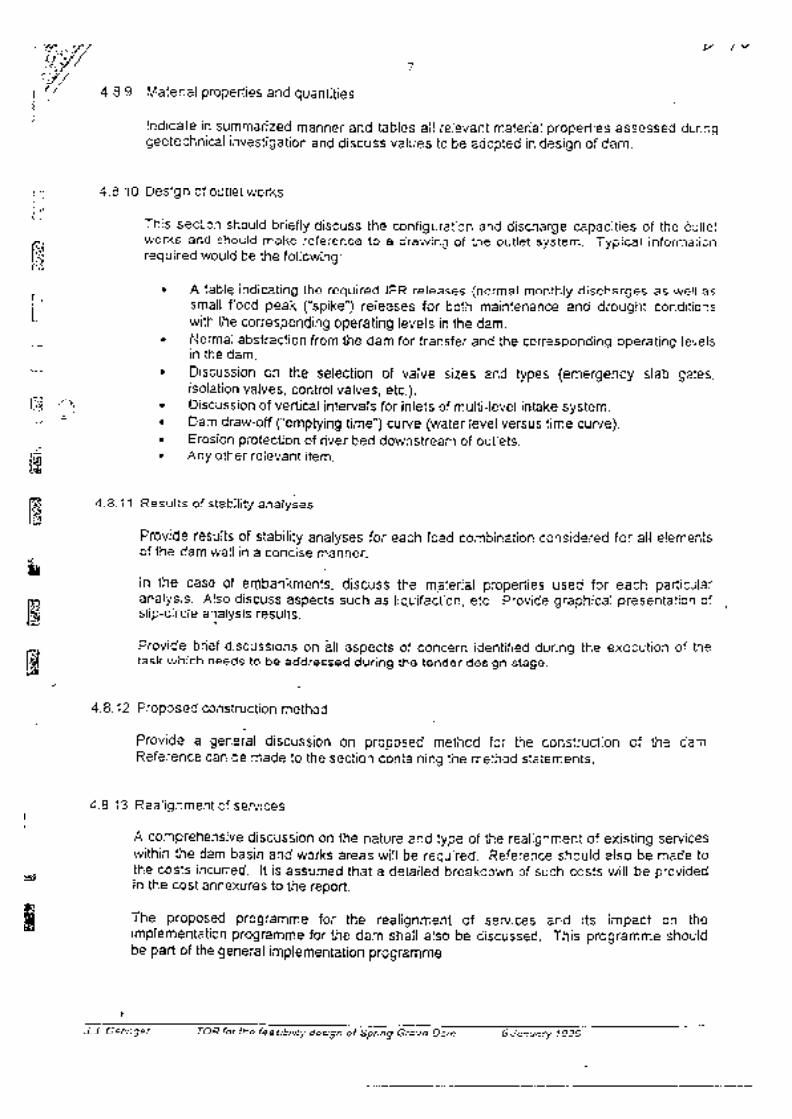


MOOI-MGENI RIVER TRANSFER SCHEME PHASE 2: FEASIBILITY STUDY
Dam Design Report January 2004 I:\3889\Documents\Feasibility Report\Report 2 _ Dam Design\SGD Design Report January 2004.doc
E. CONCRETE SPECIFICATIONS
MOOI-MGENI RIVER TRANSFER SCHEME PHASE 2: FEASIBILITY STUDY
Dam Design Report January 2004 I:\3889\Documents\Feasibility Report\Report 2 _ Dam Design\SGD Design Report January 2004.doc
F. CONSTRUCTION PROGRAMME
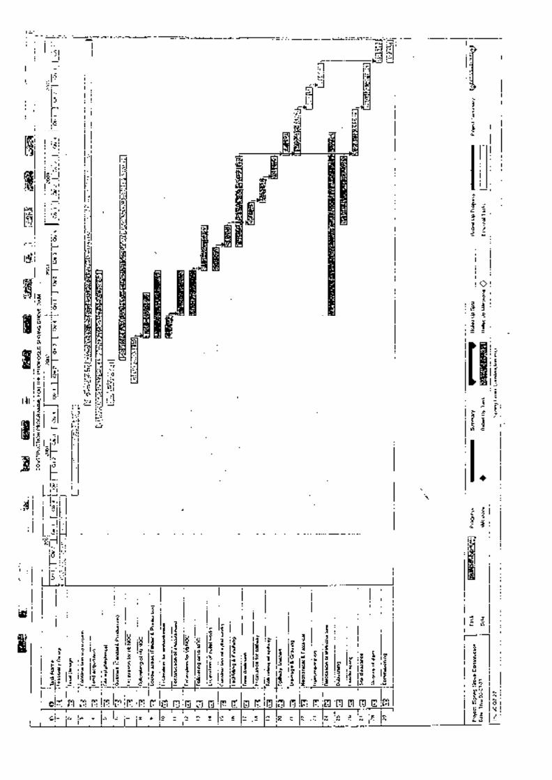

MOOI-MGENI RIVER TRANSFER SCHEME PHASE 2: FEASIBILITY STUDY
Dam Design Report January 2004 I:\3889\Documents\Feasibility Report\Report 2 _ Dam Design\SGD Design Report January 2004.doc
G. COMMENTS FROM HYDROLOGY REGARDING THE EXTREME FLOODING CONDITIONS
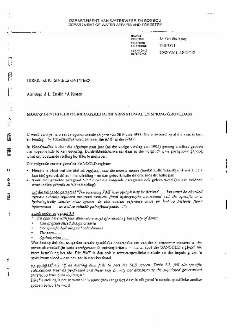

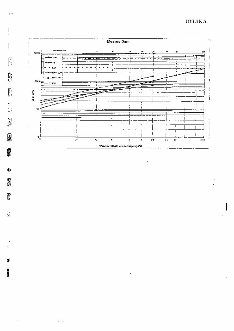
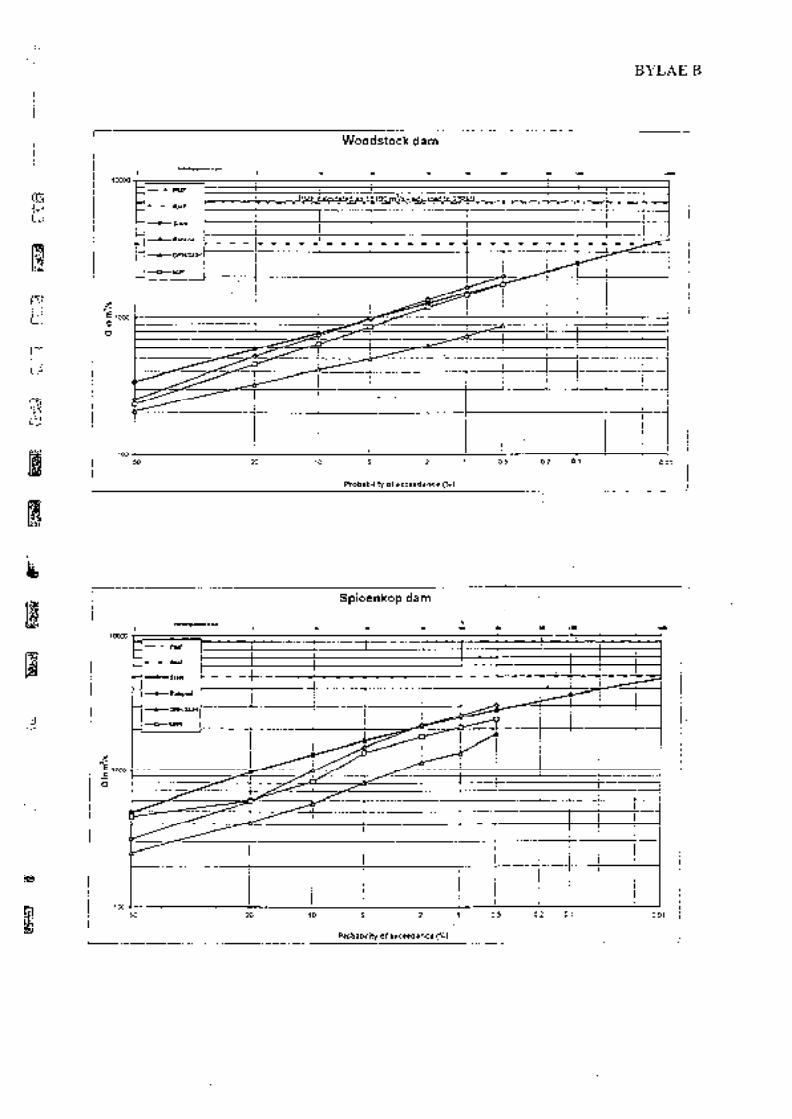
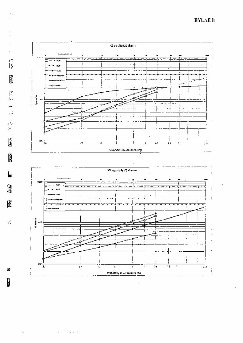
MOOI-MGENI RIVER TRANSFER SCHEME PHASE 2: FEASIBILITY STUDY
Dam Design Report January 2004 I:\3889\Documents\Feasibility Report\Report 2 _ Dam Design\SGD Design Report January 2004.doc
H. COMMENTS BY CIVIL DESIGN ON THE FEASIBILITY LEVEL DESIGN
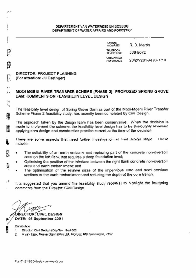


![Supporting Information - Victor Nizetnizetlab.ucsd.edu/Publications/Guani-Abx-Suppl.pdfSupporting Information! ... Wdee Thienphrapa,[b] Quang N. Dam,[b] Victor Nizet,*[b] and Yitzhak](https://img.pdfslide.net/doc/110x75/5ad93da27f8b9ab8378e67b9/supporting-information-victor-information-wdee-thienphrapab-quang-n-damb.jpg)