Embed Size (px)
Citation preview
Supramolecular Organization of Dye Molecules in Zeolite L Channels: Synthesis, Properties and Composite Materials. Pengpeng Caoa, Oleg Khorevb, André Devauxa,*, Lucie Sägesserc, Andreas Kunzmannd, Achim Eckerc, Robert Hänerb, Dominik Brühwilerc,*, Gion Calzaferrib,*, Peter Belsera,* a) Department of Chemistry, University of Fribourg, Chemin du Musée 9, CH-1700 Fribourg, Switzerland. [email protected], [email protected] b) Department of Chemistry and Biochemistry, University of Bern, Freiestrasse 3, CH-3012 Bern, Switzerland. [email protected] c) Institute of Chemistry and Biological Chemistry, Zürich University of Applied Sciences, CH-8820 Wädenswil, Switzerland. d) Optical Additives GmbH, Flurweg 9, CH-3073 Gümligen, Switzerland. ([email protected], [email protected], [email protected], [email protected], [email protected], [email protected], [email protected], [email protected], [email protected], [email protected])
ABSTRACT: Sequential insertion of different dyes into the one-dimensional channels of zeolite L (ZL) leads to supramolecular sandwich structures and allows formation of sophisticated antenna composites for light harvesting, transport, and trapping. We describe the synthesis and properties ranging from the preparation of molecules and hosts to composites, as well as composites embedded in polymer matrices, including 2- and 3-color antenna systems. Perylene diimide dyes (PDIs) are an important class of chromophores and are of great interest for the synthesis of artificial antenna systems. They are especially well suited to advancing our understanding of the structure-transport relationship in ZL because their core fits tightly through the 12-ring channel opening. The substituents at both ends of the PDIs can be varied to a large extent without influencing their electronic absorption and fluores-cence spectra. We compare the intercalation/insertion of 17 PDIs, two terrylenes, and a quaterrylene into ZL and we discuss their interaction with the inner surface of the ZL nanochannels. ZL crystals of about 500 nm in size have been used because they meet the criteria that must be respected for the preparation of antenna composites for light harvesting, transport and trapping. The photo-stability of dyes is considerably improved by inserting them into the ZL channels, as the guests are protected by being confined. Plugging the channel entrances so that the guests cannot escape to the environment is a prerequisite for achieving long term stabil-ity of composites embedded in an organic matrix. We compare successful possibilities for achieving this. Finally, embedding of dye-ZL composites in PMMA polymer matrices, while maintaining optical transparency, is reported. Our results deepen the under-standing and facilitate rational design of advanced dye-zeolite composite materials. We provide powerful tools for further develop-ing and understanding artificial antenna systems, which are among the most fascinating subjects of current photochemistry.
1. INTRODUCTION Molecules slipping through the 0.75 nm wide channel openings of zeolite L (ZL), which widen to 1.2 nm at their largest exten-sion before closing again in a periodic manner, lose much of their freedom of movement. It is essentially reduced to one-dimensional back and forth stumbling if their length approach-es or exceeds that of two unit cells (u.c.). The first conclusion would be that there are no options left for fine tuning character-istic properties of the inserted guests, and hence for influencing the properties of the resulting molecule-ZL composites. Expe-rience, however, tells a different story. The diversity of guest-ZL composites exhibiting a large range of properties is impres-sive.1-14 It emerges from the fact that the variety of molecules that fit into these narrow channels is large, and that the con-finement favors the formation of sandwich type structures (Scheme 1) including the possibility for rational stopcock modification.1,5,11,15-17 Size and morphology of the ZL host crystals can be tuned from about 30 nm to several micrometers, and from elongated to disc shaped.18-23 The composites can be organized into extended ordered structures, thus transferring microscopic qualities to the macroscopic scale.24-29 The lumi-nescence properties of nanosized rare earth ZL composites can be enormously influenced by plugging the channel entrances with an imidazolium based stopcock.17 Substitution of some of the charge-compensating potassium cations by an imidazolium cation can strongly influence the spectral characteristics of pH sensitive dyes.30 A simple covalent modification pattern of the inserted dyes allows not only to control the contact distance between the dyes, so that exciton interaction can be switched on and off,31-34 but also to influence the environment of neigh-boring dyes in a sandwich structure. The interaction of a guest’s functional group with the ZL channel is not well under-
stood. The major exception are the carbonyl groups, which were found to bind to the zeolite extra framework potassium cations and thus to be responsible for dye stabilization in the channels.35 The ZL channels can accommodate more than one type of dyes. They can either be loaded one after another, forming a sandwich dye-ZL composite, or simultaneously, which leads to a composite containing a random dye mixture. This study focuses on the sandwich type structure where the different dyes form distinct domains as the molecules are too large to pass each other inside the channels. This sandwich dye-ZL composite structure has proven to be invaluable for the realization of materials showing efficient Förster resonance energy transfer (FRET)36 antenna characteristics.30,37 We show in Scheme 1C typical patterns, a, b, b’, b’’, and c, that can be realized by inserting dyes into the channels of the hexagonal ZL crystals. Dyes that absorb light at a shorter wavelength are referred to as donors (D) while those that absorb light at a longer wavelength as acceptors (A). A system marked as dye-ZL contains only one kind of dye. A composite containing two dyes will be referred to as dye2,dye1-ZL, where the sequential insertion order is indicated by the ordering of the dye names from right to left. In this case, dye1 would have been inserted before dye2. Crystals of about 500 nm in length and diameter are convenient for many applications and have been chosen because their size meets the criteria that must be respected for the preparation of antenna composites for light harvesting, transport and trapping. They consists of about 67’000 strictly parallel channels each of which is formed by 666 u.c. of 0.75 nm in length. There is space in each channel for a maximum of 333 HR, of 222 DMP, or of about 200 m-DXP molecules (Scheme 2). High dye loadings have been realized in many cases. The maximum occupation numbers are, however, rarely
2
reached, mainly for thermodynamic and kinetic reasons. We distinguish between one-dye, two-dye, and three-dye compo-sites but we will not discuss more complex patterns. Acceptors are distributed randomly inside the crystals in composite b”. Sequential insertion for synthesizing sandwich structure com-posites is simple, in principle. However, finding the right load-ing conditions can be more difficult.37 Perylene-3,4:9,10-tetracarboxylic diimides (PDIs, Table 1) represent classical structure types of colorants that have found tremendous interest in fundamental and industrial research.38
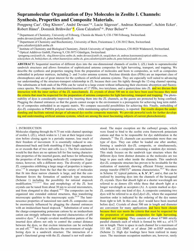
Scheme 1. Synthesis and scheme of dye-ZL composites. (A) Sequential loading strategy leading to antenna systems with the acceptor dyes placed in the middle part of the channels. (B) Schematic view of the hexagonal arrangement of the 1D ZL channels. (C) Schemes of different types of dye-ZL compo-sites. a) D-ZL; b) D,A-ZL sandwich with the acceptor located in the middle part of the host; b’) A,D-ZL sandwich; b’’) ran-
dom(D,A)-ZL; c) D1,D2,A-ZL sandwich. The colors indicate the location of the different dyes. Assembling them in a precise multi-chromophore supramo-lecular scaffold using DNA has been investigated,39 and has recently lead to the discovery of two homo-chromophoric H-aggregates.40 Insertion of PDIs into the channels of ZL in dif-ferent laboratories resulted in a variety of composites with remarkable properties.1,6,8,23,30,31 Most of our PDI-ZL experi-ments have been performed with DXP and tb-DXP. These dyes cannot be inserted at room temperature. Their largest van der Waals diameter is about 0.76 nm and therefore exceeds the 0.72 nm van der Waals diameter of the ZL channel opening.41 Therefore, insertion is performed under vacuum conditions at about 200 °C. At this temperature the breathing vibrational modes of the 12-ring channel entrance of ZL are fully activat-ed42 and the PDIs can slip through. In zeolite nomenclature, a 12-ring consists of 12 T atoms (T = Si, Al) plus 12 bridging oxygen atoms.41,42 Conditions and structural details enhancing or inhibiting the insertion and transport in ZL channels are, however, not well understood. We therefore report a compari-son between 17 differently substituted PDIs, two terrylene diimides (TDI), and a quaterrylene diimide (QDI) (Tables 1 and 2). PDIs are especially well suited for studying the struc-ture-transport relationship of dyes in ZL because their core fits tightly through the 12-ring channel opening and the substitu-ents at both ends of the dyes can be easily varied without sig-nificantly influencing their electronic absorption and fluores-cence spectra. Sequential insertion of different dyes leads to sandwich structures and hence allows formation of sophisticat-ed antenna composites for light harvesting, transport, and trap-ping. In this paper we set out to describe the synthesis of a rationally-designed library of substituted PDIs, TDIs and a QDI and to correlate the substituent type with insertion behav-ior and properties of the resultant composites, including 2- and 3-color antenna systems.
Scheme 2. Upper: comparison of the length of the three dyes, HR (1.5 nm), DMP (2 nm), and m-DXP (2.4 nm), with the u.c. length of ZL. The two yellow vertical lines mark the 1.5 nm length of two u.c.. Lower: illustration of the van der Waals surface of tb-DXP (2.7 nm; upper) and ADE-XP (3.1 nm;
3
lower) with the 12-ring channel opening of ZL. Numbers in parentheses are the van der Waals length of the molecules (see Tables 1 and 2 for structures). It is convenient to describe the loading of a dye-ZL composite in terms of the occupation probability or loading p, which is defined as the ratio between the numbers of occupied sites divided by the total number of sites available. The value of p ranges from 0 for an empty ZL to 1 for a fully loaded one. A site expresses the number of u.c. occupied by a guest. The dye concentration in terms of mol/volume as a function of p is expressed by equation (1) where nS is the number of u.c. that can be occupied by a guest:1 𝑐 𝑝 = 0.752 !
!!(!"#!) (1)
The number in the composite name, such as dye-ZL.31 indi-cates the dye loading p. In a sandwich composite of two dyes, we write dye1,dye2-ZL.05,.12 where .05 refers to dye2 and .12 to dye1. The default 3.6 charge compensating cations per u.c. of ZL, which can be replaced by means of cation exchange, are K+. We often replace some of them by the organic cation IMZ+.43 The name of such composites is e.g. dye1,dye2-ZL.05,.12(0.5IMZ+) which means that 0.5 K+ per u.c. have been replaced by IMZ+. 2. RESULTS AND DISCUSSION 2.1. Synthesis of Dyes. The preparation of the investigated rylene dyes can be divided into the following classes: a) com-mercially available dyes, b) perylene dyes (PDIs), c) terrylene dyes (TDIs) and d) quaterrylene dyes (QDIs); Tables 1 and 2. a) Commercially available dyes. The following commercially available dyes were investigated in the present paper: 2,9-bis(2,6-dimethylphenyl)anthra[2,1,9-def:6,5,10-d'e'f']diiso-quinoline-1,3,8,10(2H,9H) tetra-one (DXP), 2,9-bis(3,5-dimethylphenyl) anthra[2,1,9-def:6,5,10-d'e'f']diisoquinoline-1,3,8,10 (2H,9H)-tetraone (Pigment Red 149, we have used the abbreviation dm-XP), 14H-anthra[2,1,9-mna]thio-xanthen-14-one (Hostasol Red, HR) and 1,4-bis(4-methyl-5-phenyl-oxazol-2-yl)benzene (DMP). b) Perylene dyes (PDIs). Mostly all perylene dyes were pre-pared by applying a simple condensation reaction in which perylene-3,4,9,10-tetracarboxylic dianhydride (1) was treated with appropriate amines in quinoline or imidazole as solvent and zinc acetate as catalyst at 180 0C – 240 oC for several hours under an inert atmosphere, and the yields were in the range of 7% to 95% (Scheme 3). Therefore, the main challenge was the preparation of the corresponding amines.
R NH2 O O
O
O
O
O
N N
O
O
O
O
R R+2 + 2 H2Oa)
1 Scheme 3. General synthesis of perylene dyes. Conditions: Zn(OAc)2, imidazole/quinoline/ diethanolamine, 190 0C – 250 oC, 4 – 48 h, 7% – 95% yield. Some of the investigated amines are commercially available, but by economic reasons, we have prepared it in our laborato-ries. The perylene dyes which were prepared from commercial-ly available amines are the following (in parentheses the reac-tion conditions): DXP (Zn(OAc)2, quinoline, 230 oC, 4 h, 73%), DEXP (Zn(OAc)2, quinoline, 220 oC, 24 h, 47%), DIXP (Zn(OAc)2, imidazole, 140 oC, 24 h, 8%), tb-XP (diethanola-mine, 180 oC, 6 h, 78%), m-DXP (Zn(OAc)2, quinoline, 230 oC, 4 h, 73%), and b-XP (Zn(OAc)2, quinoline, 230 oC, 4 h, 95%).
NH2
NN
O
OO
ONO2
32 dm-DXP
(a) (b)
N N
O
O
O
O
BocHN
NH2
Br B(OH)2
NHBoc
Br
NH2
dmp-DXP
7
5
8
(a) (b) (c)
(d)
4
6
A
C
NH2
O
NH2 NH2
N N
O
O O
O
10 11
b-DXP
(a) (b) (c)
9
B
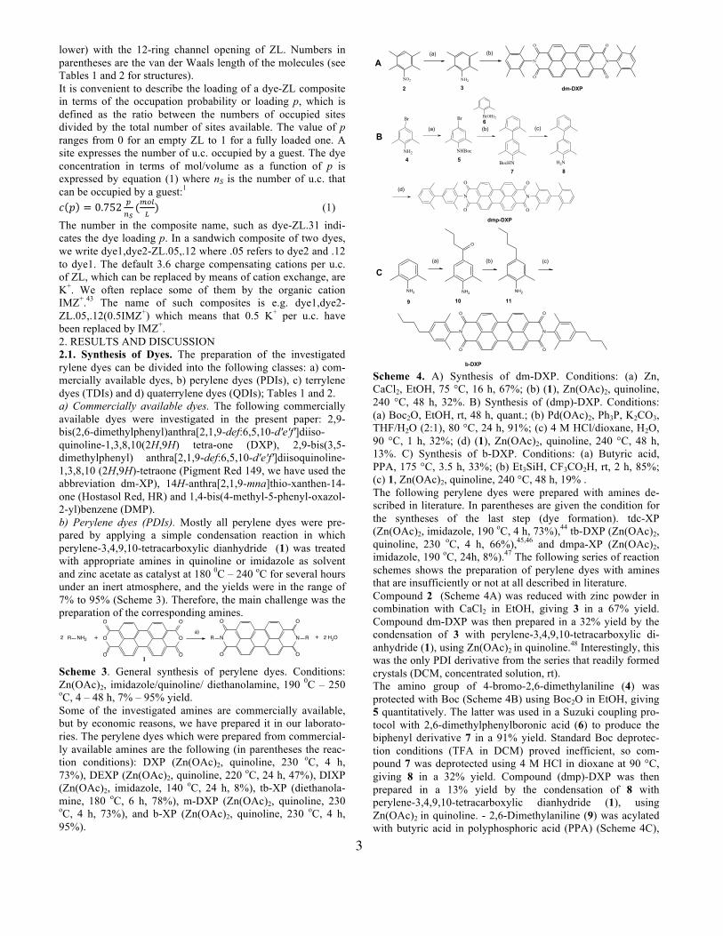
Scheme 4. A) Synthesis of dm-DXP. Conditions: (a) Zn, CaCl2, EtOH, 75 °C, 16 h, 67%; (b) (1), Zn(OAc)2, quinoline, 240 °C, 48 h, 32%. B) Synthesis of (dmp)-DXP. Conditions: (a) Boc2O, EtOH, rt, 48 h, quant.; (b) Pd(OAc)2, Ph3P, K2CO3, THF/H2O (2:1), 80 °C, 24 h, 91%; (c) 4 M HCl/dioxane, H2O, 90 °C, 1 h, 32%; (d) (1), Zn(OAc)2, quinoline, 240 °C, 48 h, 13%. C) Synthesis of b-DXP. Conditions: (a) Butyric acid, PPA, 175 °C, 3.5 h, 33%; (b) Et3SiH, CF3CO2H, rt, 2 h, 85%; (c) 1, Zn(OAc)2, quinoline, 240 °C, 48 h, 19% . The following perylene dyes were prepared with amines de-scribed in literature. In parentheses are given the condition for the syntheses of the last step (dye formation). tdc-XP (Zn(OAc)2, imidazole, 190 oC, 4 h, 73%),44 tb-DXP (Zn(OAc)2, quinoline, 230 oC, 4 h, 66%),45,46 and dmpa-XP (Zn(OAc)2, imidazole, 190 oC, 24h, 8%).47 The following series of reaction schemes shows the preparation of perylene dyes with amines that are insufficiently or not at all described in literature. Compound 2 (Scheme 4A) was reduced with zinc powder in combination with CaCl2 in EtOH, giving 3 in a 67% yield. Compound dm-DXP was then prepared in a 32% yield by the condensation of 3 with perylene-3,4,9,10-tetracarboxylic di-anhydride (1), using Zn(OAc)2 in quinoline.48 Interestingly, this was the only PDI derivative from the series that readily formed crystals (DCM, concentrated solution, rt). The amino group of 4-bromo-2,6-dimethylaniline (4) was protected with Boc (Scheme 4B) using Boc2O in EtOH, giving 5 quantitatively. The latter was used in a Suzuki coupling pro-tocol with 2,6-dimethylphenylboronic acid (6) to produce the biphenyl derivative 7 in a 91% yield. Standard Boc deprotec-tion conditions (TFA in DCM) proved inefficient, so com-pound 7 was deprotected using 4 M HCl in dioxane at 90 °C, giving 8 in a 32% yield. Compound (dmp)-DXP was then prepared in a 13% yield by the condensation of 8 with perylene-3,4,9,10-tetracarboxylic dianhydride (1), using Zn(OAc)2 in quinoline. - 2,6-Dimethylaniline (9) was acylated with butyric acid in polyphosphoric acid (PPA) (Scheme 4C),
4
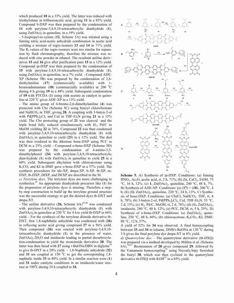
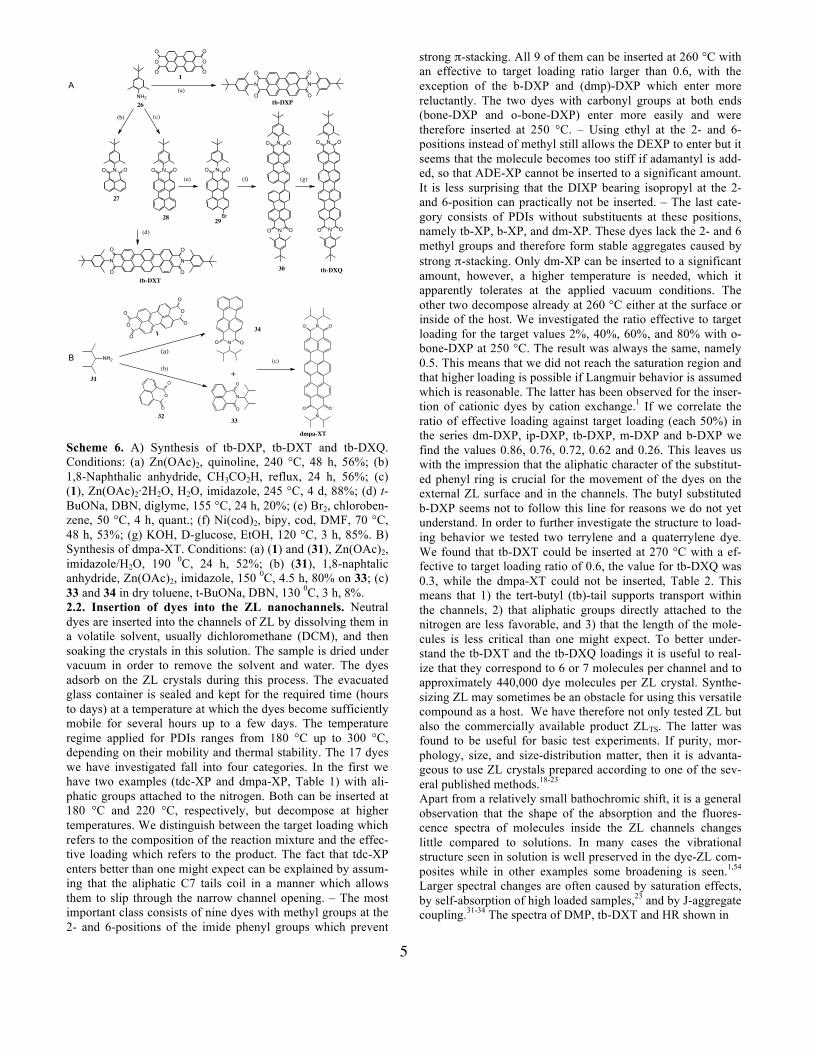
which produced 10 in a 33% yield. The latter was reduced with triethylsilane in trifluoroacetic acid, giving 11 in a 85% yield. Compound b-DXP was then prepared by the condensation of 11 with perylene-3,4,9,10-tetracarboxylic dianhydride (1), using Zn(OAc)2 in quinoline, in a 19% yield. - 5-Isopropyl-m-xylene (12, Scheme 5A) was nitrated using a fuming nitric acid-acetic anhydride combination in acetic acid yielding a mixture of regio-isomers 13 and 14 in 71% yield. The Rf values of the regio-isomers were too similar for separa-tion by flash chromatography, therefore the mixture was re-duced with zinc powder in ethanol. The resultant aniline deriv-atives 15 and 16 give after purification pure 15 in a 12% yield. Compound ip-DXP was then prepared by the condensation of 15 with perylene-3,4,9,10-tetracarboxylic dianhydride (1), using Zn(OAc)2 in quinoline, in a 7% yield. - Compound ADE-XP (Scheme 5B) was prepared by the condensation of 2,6-diethylaniline (17) (commercially available) with 1-bromoadamantane (18) (commercially available) at 200 0C during 4 h giving 19 in a 48% yield. Subsequent condensation of 19 with PTCDA (1) using zink acetate as catalyst in quino-line at 220 0C gives ADE-XP in a 13% yield. - The amino group of 4-bromo-2,6-dimethylaniline (4) was protected with Cbz (Scheme 5C) using benzyl chloroformate and NaHCO3 in THF, giving 20. A coupling with 3-butyn-2-ol with Pd[PPh3]2Cl2 and CuI in THF-Et3N giving 21 in a 15% yield. The Cbz protecting group of 21 was cleaved and the triple bond fully reduced simultaneously with H2, Pd/C in MeOH yielding 22 in 76%. Compound 22 was then condensed with perylene-3,4,9,10-tetracarboxylic dianhydride (1) with Zn(OAc)2 in quinoline to yield (23) in a 12% yield. The diol was then oxidized to the diketone bone-DXP using PCC in DCM in a 25% yield. - Compound o-bone-DXP (Scheme 5D) was prepared by the condensation of 4-amino-3,5-dimethylphenol (24) with perylene-3,4,9,10-tetracarboxylic dian-hydride (1) with Zn(OAc)2 in quinoline to yield 25 in a 60% yield. Subsequent alkylation with chloroacetone using K2CO3 and KI in DMF gave o-bone-DXP in a 57% yield. The synthesis procedures for tdc-XP, dmpa-XP, b-XP, tb-XP, m-DXP, tb-DXP, DIXP, and DEXP are described in the SI. c) Terrylene dyes. The terrylene dyes are more challenging to synthesize.49 An appropriate dianhydride precursor like (1) for the preparation of perylene dyes is missing. Therefore a step-by-step construction to build up the terrylene ground structure was the successful strategy to get the desired dyes tb-DXT and dmpa-XT. - The aniline derivative (26, Scheme 6A)45,46 was condensed with perylene-3,4,9,10-tetracarboxylic dianhydride (1) with Zn(OAc)2 in quinoline at 230 0C for 4 h to yield tb-DXP in 66% yield. - For the synthesis of the terrylene diimide derivative tb-DXT, first 1,8-naphthalic anhydride was condensed with (26) in refluxing acetic acid giving compound 27 in a 56% yield. Then compound (26) was reacted with perylene-3,4,9,10-tetracarboxylic dianhydride (1) in the presence of water, Zn(OAc)2·2H2O and imidazole leading to partial decarboxyla-tion-condensation to yield the monoimide derivative 28. The latter was then fused with 27 using t-BuONa/DBN in diglyme49 to give tb-DXT in a 20% yield. − 1,8-Naphtalic anhydride (32) and 31 are coupled at 150 0C to get the corresponding 1,8-naphtalic imide 33 in 80% yield. In a similar reaction were (1) and 31 under catalytic conditions in an imidazole/water mix-ture at 1900C during 24 h coupled to 34.
Scheme 5. A) Synthesis of ip-DXP. Conditions: (a) fuming HNO3, Ac2O, acetic acid, rt, 2 h, 71%; (b) Zn, CaCl2, EtOH, 75 °C, 16 h, 12%; (c) 1, Zn(OAc)2, quinoline, 240 °C, 48 h, 7%. B) Synthesis of ADE-XP. Conditions: (a) (17) + (18), 200 0C, 4 h; (b) (1), Zn(OAc)2, quinoline, 220 °C, 24 h, 13%. C) Synthe-sis of bone-DXP. Conditions: (a) CbzCl, NaHCO3, THF, rt, 8 h, 78%; (b) 3-butyn-2-ol, Pd[PPh3]2Cl2, CuI, THF-Et3N, 55 °C, 2 d, 15%; (c) H2, Pd/C, MeOH, rt, 2 d, 76%; (d) (1), Zn(OAc)2, imidazole, 240 °C, 48 h, 12%; (e) PCC, DCM, rt, 5 h, 25%. D) Synthesis of o-bone-DXP. Conditions: (a) Zn(OAc)2, quino-line, 250 °C, 48 h, 60%; (b) chloroacetone, K2CO3, KI, DMF, 80 °C, 12 h, 57%. A yield of 52% for 34 was observed. A final homocoupling between 33 and 34 in toluene, DNB/t-BuONa at 130 0C during 3 h gives the final perylene dye dmpa-XT in 8% yield. d) Quaterrylene dye. - The quaterrylene derivative (tb-DXQ) was prepared via a method developed by Müllen et al. (Scheme 6A).50,51 Bromination of 28 gives compound 29, followed by the Yamamoto homocoupling52 using Ni(cod)2/bipy furnished the biaryl 30, which was then cyclized to the quaterrylene derivative tb-DXQ with KOH53 in a 85% yield.
NN
O
OO
O
NO2 NH2
NO2 NH2
ip-DXP
+
13 15
+
16
(a) (b)
(c)
12 14
NH2 Br
H2N O
O OO
OO
NN
O
O
O
O
+ (a)
(b)
ADE-XP
17 18 19
1
NN
O
OO
O
OH
HO
NH2
OH
NHCbz
HO
Br
NHCbz
NN
O
OO
O
O
O
Br
NH2
21 2220
23
bone-DXP
(a) (b) (c) (d)
(e)
4
N
N
O O
OO
OH
OH
O
O
O O
OO
N
N
O O
OO
O
O
O
O
NH2
OH
25
o-bone-DXP(a) (b)
24
1
A
B
C
D
5
NN
O
OO
O
O
O
O
O
O
O
N
O
O
N
O
O
N OO
NO O
N OO
NO O
N OO
Br
N OO
NH2
N OO
26
1
tb-DXP
27
28
tb-DXT
29
30
(a)
(b) (c)
(d)
(e) (f) (g)
tb-DXQ
NH2
O
O
O
O
O
ONO O
N
O
O
O
O
O
N OO
OO
N
31
(a)
(b) +(c)
134
33
dmpa-XT
32
A
B
Scheme 6. A) Synthesis of tb-DXP, tb-DXT and tb-DXQ. Conditions: (a) Zn(OAc)2, quinoline, 240 °C, 48 h, 56%; (b) 1,8-Naphthalic anhydride, CH3CO2H, reflux, 24 h, 56%; (c) (1), Zn(OAc)2·2H2O, H2O, imidazole, 245 °C, 4 d, 88%; (d) t-BuONa, DBN, diglyme, 155 °C, 24 h, 20%; (e) Br2, chloroben-zene, 50 °C, 4 h, quant.; (f) Ni(cod)2, bipy, cod, DMF, 70 °C, 48 h, 53%; (g) KOH, D-glucose, EtOH, 120 °C, 3 h, 85%. B) Synthesis of dmpa-XT. Conditions: (a) (1) and (31), Zn(OAc)2, imidazole/H2O, 190 0C, 24 h, 52%; (b) (31), 1,8-naphtalic anhydride, Zn(OAc)2, imidazole, 150 0C, 4.5 h, 80% on 33; (c) 33 and 34 in dry toluene, t-BuONa, DBN, 130 0C, 3 h, 8%. 2.2. Insertion of dyes into the ZL nanochannels. Neutral dyes are inserted into the channels of ZL by dissolving them in a volatile solvent, usually dichloromethane (DCM), and then soaking the crystals in this solution. The sample is dried under vacuum in order to remove the solvent and water. The dyes adsorb on the ZL crystals during this process. The evacuated glass container is sealed and kept for the required time (hours to days) at a temperature at which the dyes become sufficiently mobile for several hours up to a few days. The temperature regime applied for PDIs ranges from 180 °C up to 300 °C, depending on their mobility and thermal stability. The 17 dyes we have investigated fall into four categories. In the first we have two examples (tdc-XP and dmpa-XP, Table 1) with ali-phatic groups attached to the nitrogen. Both can be inserted at 180 °C and 220 °C, respectively, but decompose at higher temperatures. We distinguish between the target loading which refers to the composition of the reaction mixture and the effec-tive loading which refers to the product. The fact that tdc-XP enters better than one might expect can be explained by assum-ing that the aliphatic C7 tails coil in a manner which allows them to slip through the narrow channel opening. – The most important class consists of nine dyes with methyl groups at the 2- and 6-positions of the imide phenyl groups which prevent
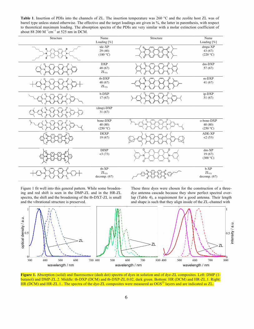
strong π-stacking. All 9 of them can be inserted at 260 °C with an effective to target loading ratio larger than 0.6, with the exception of the b-DXP and (dmp)-DXP which enter more reluctantly. The two dyes with carbonyl groups at both ends (bone-DXP and o-bone-DXP) enter more easily and were therefore inserted at 250 °C. – Using ethyl at the 2- and 6-positions instead of methyl still allows the DEXP to enter but it seems that the molecule becomes too stiff if adamantyl is add-ed, so that ADE-XP cannot be inserted to a significant amount. It is less surprising that the DIXP bearing isopropyl at the 2- and 6-position can practically not be inserted. – The last cate-gory consists of PDIs without substituents at these positions, namely tb-XP, b-XP, and dm-XP. These dyes lack the 2- and 6 methyl groups and therefore form stable aggregates caused by strong π-stacking. Only dm-XP can be inserted to a significant amount, however, a higher temperature is needed, which it apparently tolerates at the applied vacuum conditions. The other two decompose already at 260 °C either at the surface or inside of the host. We investigated the ratio effective to target loading for the target values 2%, 40%, 60%, and 80% with o-bone-DXP at 250 °C. The result was always the same, namely 0.5. This means that we did not reach the saturation region and that higher loading is possible if Langmuir behavior is assumed which is reasonable. The latter has been observed for the inser-tion of cationic dyes by cation exchange.1 If we correlate the ratio of effective loading against target loading (each 50%) in the series dm-DXP, ip-DXP, tb-DXP, m-DXP and b-DXP we find the values 0.86, 0.76, 0.72, 0.62 and 0.26. This leaves us with the impression that the aliphatic character of the substitut-ed phenyl ring is crucial for the movement of the dyes on the external ZL surface and in the channels. The butyl substituted b-DXP seems not to follow this line for reasons we do not yet understand. In order to further investigate the structure to load-ing behavior we tested two terrylene and a quaterrylene dye. We found that tb-DXT could be inserted at 270 °C with a ef-fective to target loading ratio of 0.6, the value for tb-DXQ was 0.3, while the dmpa-XT could not be inserted, Table 2. This means that 1) the tert-butyl (tb)-tail supports transport within the channels, 2) that aliphatic groups directly attached to the nitrogen are less favorable, and 3) that the length of the mole-cules is less critical than one might expect. To better under-stand the tb-DXT and the tb-DXQ loadings it is useful to real-ize that they correspond to 6 or 7 molecules per channel and to approximately 440,000 dye molecules per ZL crystal. Synthe-sizing ZL may sometimes be an obstacle for using this versatile compound as a host. We have therefore not only tested ZL but also the commercially available product ZLTS. The latter was found to be useful for basic test experiments. If purity, mor-phology, size, and size-distribution matter, then it is advanta-geous to use ZL crystals prepared according to one of the sev-eral published methods.18-23 Apart from a relatively small bathochromic shift, it is a general observation that the shape of the absorption and the fluores-cence spectra of molecules inside the ZL channels changes little compared to solutions. In many cases the vibrational structure seen in solution is well preserved in the dye-ZL com-posites while in other examples some broadening is seen.1,54 Larger spectral changes are often caused by saturation effects, by self-absorption of high loaded samples,23 and by J-aggregate coupling.31-34 The spectra of DMP, tb-DXT and HR shown in
6
Figure 1 fit well into this general pattern. While some broaden-ing and red shift is seen in the DMP-ZL and in the HR-ZL spectra, the shift and the broadening of the tb-DXT-ZL is small and the vibrational structure is preserved.
These three dyes were chosen for the construction of a three-dye antenna cascade because they show perfect spectral over-lap (Table 4), a requirement for a good antenna. Their length and shape is such that they align inside of the ZL-channel with
Table 1. Insertion of PDIs into the channels of ZL. The insertion temperature was 260 °C and the zeolite host ZL was of barrel type unless stated otherwise. The effective and the target loadings are given in %, the latter in parenthesis, with respect to theoretical maximum loading. The absorption spectra of the PDIs are very similar with a molar extinction coefficient of about 88 200 M−1cm−1 at 525 nm in DCM.
Structure Name Loading [%]
Structure
Name Loading [%]
tdc-XP 29 (40)
(180 °C)
dmpa-XP 43 (67)
(220 °C)
DXP 48 (67) ZLTS
dm-DXP 57 (67)
tb-DXP 48 (67) ZLTS
m-DXP 41 (67)
b-DXP 17 (67)
ip-DXP 51 (67)
(dmp)-DXP 31 (67)
bone-DXP 40 (80)
(250 °C)
o-bone-DXP 40 (80)
(250 °C)
DEXP 19 (67)
ADE-XP <2 (53)
DIXP <3 (73) N
O
O
N
O
O
dm-XP 19 (67)
(300 °C)
tb-XP ZLTS
decomp. (67)
b-XP ZLTS
decomp. (67)
Figure 1. Absorption (solid) and fluorescence (dash dot) spectra of dyes in solution and of dye-ZL composites. Left: DMP (1-butanol) and DMP-ZL.2. Middle: tb-DXP (DCM) and tb-DXP-ZL.0.02, dark green. Bottom: HR (DCM) and HR-ZL.1. Right: HR (DCM) and HR-ZL.1.. The spectra of the dye-ZL composites were measured as OGS23 layers and are indicated as ZL.
NN
O
O
O
O
N
O
O
N
O
O
O O
O
O
N N
O
O
O
O
7
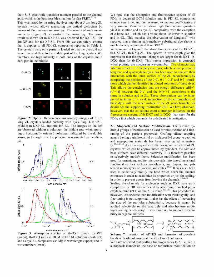
their S0-S1 electronic transition moment parallel to the channel axis, which is the best possible situation for fast FRET.36,55 This was tested by inserting the dyes into about 5 µm long ZL crystals, which allows measuring the optical dichroism by means of fluorescence microscopy. The results of such meas-urements (Figure 2) demonstrate the anisotropy. The same result as shown for m-DXP-ZL was observed for DXP-ZL, for dm-XP and for tdc-XP-ZL. From this we can safely assume that it applies to all PDI-ZL composites reported in Table 1. The crystals were only partially loaded so that the dyes did not have time to diffuse to the middle part of the long crystals. We therefore see high intensity at both ends of the crystals and a dark part in the middle.
Figure 2: Optical fluorescence microscopy images of 5 µm long ZL crystals loaded partially with dyes. Top: DMP-ZL. Middle: m-DXP-ZL. Bottom: HR-ZL. The images on the left are observed without a polarizer, the middle row when apply-ing a horizontally oriented polarizer, indicated by the double arrow, in the right row the polarizer was oriented perpendicu-lar.
Figure 3. Absorption spectra of tb-DXP (blue), tb-DXT (green), tb-DXQ (red) in DCM 5x10⁻⁶ M solutions (dash dot) and as dye-ZL composites (solid); in wavelength (upper) and in wavenumber (lower).
We note that the absorption and fluorescence spectra of all PDIs in degassed DCM solution and in PDI-ZL composites change very little, and the measured extinction coefficients are very similar. Moreover all show high fluorescence quantum yield in solution and as dye-ZL composites, with the exception of o-bone-DXP which has a value about 10 lower in solution and in ZL. This matches the observation of Langhals56 who reported that a similar para-methoxy substituted dye shows a much lower quantum yield than DXP.23 We compare in Figure 3 the absorption spectra of tb-DXP-ZL, tb-DXT-ZL, tb-DXQ-ZL. The spectra in wavelength give the impression that the spectral changes are larger for tb-DXT, tb-DXQ than for tb-DXP. This wrong impression is corrected when plotting the spectra in wavenumber. The characteristic vibronic structure of the perylene dyes, which is also present in terrylene and quaterrylene dyes, has been used to analyze their interaction with the inner surface of the ZL nanochannels by comparing the positions of the 0-0’, 0-1’, 0-2’ and 0-3’ transi-tions which can be identified in diluted solutions of these dyes. This allows the conclusion that the energy difference ΔE[ν’-(ν’+1)] between the 0-ν’ and the 0-(ν’+1) transitions is the same in solution and in ZL. These observations can be inter-preted in terms of a weak interaction of the chromophore of these dyes with the inner surface of the ZL nanochannels; for details see the supporting information (SI). We have observed, however, that the co-cations exert a stronger influence on the fluorescence spectra of tb-DXT and tb-DXQ than seen for the PDIs, a fact which demands for a dedicated investigation. 2.3. Stopcock and Surface Modification. The surface hy-droxyl groups of zeolites can be used for modification and fine-tuning of the particle properties. Grafting silane coupling agents having a trialkoxysilyl or trichlorosilyl group to zeolites and mesoporous materials has been investigated extensive-ly.13,25,57-60 As a consequence of the hexagonal structure of ZL crystals, which can be approximated by cylinders, the coat and base surfaces have different reactivity. It is therefore possible to selectively modify them. Selective modification has been used for organizing zeolite microcrystals into two-dimensional functional entities such as monolayers, multilayers, and pat-terned monolayers on various substrates.24-28 It has also been used to selectively modify the base which bears the channel entrances in order to customize its properties or just for sealing, in order to prevent guests from leaving the channels.1,5,60,61 Sealing the channels for molecules such as DXP, rare earth complexes, or HR was achieved by adsorbing branched poly-ethyleneimine (PEI) on the ZL surface.30,62,63 This procedure is, however, less specific than modification with trialkoxysilyl and fine-tuning is not supported. It also has the effect of increasing the size of the particles substantially, because it cannot be applied selectively on the base only and also because multi-layer coating is necessary. It was found not to support dispersi-bility in organic matrices.
OHOSi
O ONH2
O
SiO O
NH3+H3O
+ZL channel ZL channel
Scheme 7. Insertion of APTES and formation of covalent bonds with silanol groups at the ZL channel entrances. We have observed that grafting trialkoxysilanes to ZL, either in a stopcock manner on the base or for surface modification on
8
the coat, leads to superior properties and makes them more versatile for handling as functional composite particles. Modi-fication of ZL surfaces with trialkoxysilyl agents has been used to synthesize oriented monolayers of zeolite crystals on differ-ent substrates.24-28 We have therefore tested the molecules collected in Table 3 for surface modification. The stopcock modification reaction is explained for APTES in Scheme 7. APTES adsorbs specifically at the basal surface of the ZL crystals at the acidic1,30 channel entrances, which encourages
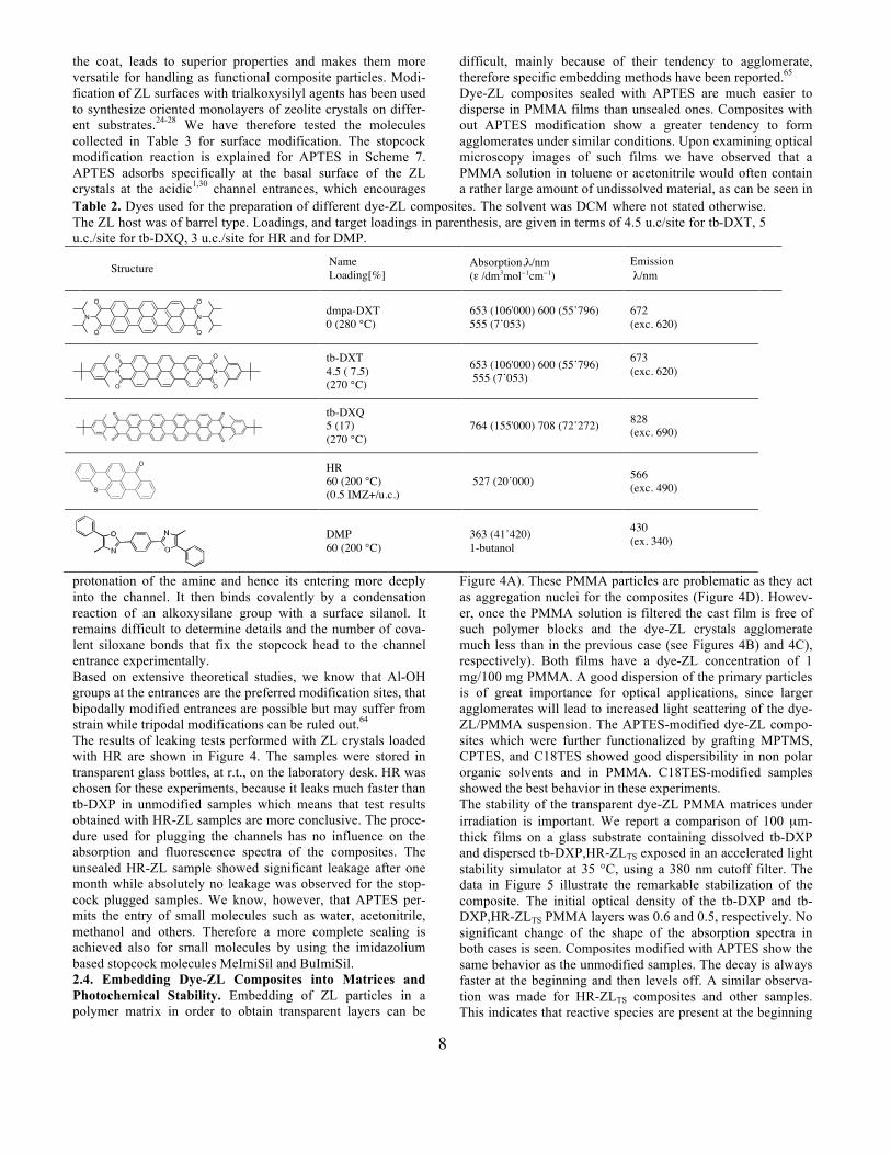
protonation of the amine and hence its entering more deeply into the channel. It then binds covalently by a condensation reaction of an alkoxysilane group with a surface silanol. It remains difficult to determine details and the number of cova-lent siloxane bonds that fix the stopcock head to the channel entrance experimentally. Based on extensive theoretical studies, we know that Al-OH groups at the entrances are the preferred modification sites, that bipodally modified entrances are possible but may suffer from strain while tripodal modifications can be ruled out.64 The results of leaking tests performed with ZL crystals loaded with HR are shown in Figure 4. The samples were stored in transparent glass bottles, at r.t., on the laboratory desk. HR was chosen for these experiments, because it leaks much faster than tb-DXP in unmodified samples which means that test results obtained with HR-ZL samples are more conclusive. The proce-dure used for plugging the channels has no influence on the absorption and fluorescence spectra of the composites. The unsealed HR-ZL sample showed significant leakage after one month while absolutely no leakage was observed for the stop-cock plugged samples. We know, however, that APTES per-mits the entry of small molecules such as water, acetonitrile, methanol and others. Therefore a more complete sealing is achieved also for small molecules by using the imidazolium based stopcock molecules MeImiSil and BuImiSil. 2.4. Embedding Dye-ZL Composites into Matrices and Photochemical Stability. Embedding of ZL particles in a polymer matrix in order to obtain transparent layers can be
difficult, mainly because of their tendency to agglomerate, therefore specific embedding methods have been reported.65 Dye-ZL composites sealed with APTES are much easier to disperse in PMMA films than unsealed ones. Composites with out APTES modification show a greater tendency to form agglomerates under similar conditions. Upon examining optical microscopy images of such films we have observed that a PMMA solution in toluene or acetonitrile would often contain a rather large amount of undissolved material, as can be seen in
Figure 4A). These PMMA particles are problematic as they act as aggregation nuclei for the composites (Figure 4D). Howev-er, once the PMMA solution is filtered the cast film is free of such polymer blocks and the dye-ZL crystals agglomerate much less than in the previous case (see Figures 4B) and 4C), respectively). Both films have a dye-ZL concentration of 1 mg/100 mg PMMA. A good dispersion of the primary particles is of great importance for optical applications, since larger agglomerates will lead to increased light scattering of the dye-ZL/PMMA suspension. The APTES-modified dye-ZL compo-sites which were further functionalized by grafting MPTMS, CPTES, and C18TES showed good dispersibility in non polar organic solvents and in PMMA. C18TES-modified samples showed the best behavior in these experiments. The stability of the transparent dye-ZL PMMA matrices under irradiation is important. We report a comparison of 100 µm-thick films on a glass substrate containing dissolved tb-DXP and dispersed tb-DXP,HR-ZLTS exposed in an accelerated light stability simulator at 35 °C, using a 380 nm cutoff filter. The data in Figure 5 illustrate the remarkable stabilization of the composite. The initial optical density of the tb-DXP and tb-DXP,HR-ZLTS PMMA layers was 0.6 and 0.5, respectively. No significant change of the shape of the absorption spectra in both cases is seen. Composites modified with APTES show the same behavior as the unmodified samples. The decay is always faster at the beginning and then levels off. A similar observa-tion was made for HR-ZLTS composites and other samples. This indicates that reactive species are present at the beginning
Table 2. Dyes used for the preparation of different dye-ZL composites. The solvent was DCM where not stated otherwise. The ZL host was of barrel type. Loadings, and target loadings in parenthesis, are given in terms of 4.5 u.c/site for tb-DXT, 5 u.c./site for tb-DXQ, 3 u.c./site for HR and for DMP.
Structure Name Loading[%]
Absorption,λ/nm (ε /dm3mol−1cm−1)
Emission λ/nm
N
O
OO
O
N
dmpa-DXT 0 (280 °C)
653 (106'000) 600 (55’796) 555 (7’053)
672 (exc. 620)
N
O
O
N
O
O
tb-DXT 4.5 ( 7.5) (270 °C)
653 (106'000) 600 (55’796) 555 (7’053)
673 (exc. 620)
tb-DXQ 5 (17) (270 °C)
764 (155'000) 708 (72’272) 828 (exc. 690)
S
O
HR 60 (200 °C) (0.5 IMZ+/u.c.)
527 (20’000) 566 (exc. 490)
DMP 60 (200 °C)
363 (41’420) 1-butanol
430 (ex. 340)
9
but are gradually used up. The decay rate slows down as a consequence and becomes perhaps controlled by transport kinetics. This is supported by the observation that layers of larger optical density are photochemically more stable. It is necessary to compare samples of similar optical density.
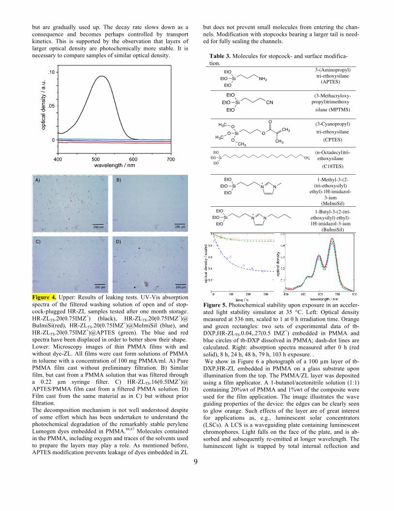
Figure 4. Upper: Results of leaking tests. UV-Vis absorption spectra of the filtered washing solution of open and of stop-cock-plugged HR-ZL samples tested after one month storage. HR-ZLTS.20(0.75IMZ+) (black), HR-ZLTS.20(0.75IMZ+)@ BuImiSi(red), HR-ZLTS.20(0.75IMZ+)@MeImiSil (blue), and HR-ZLTS.20(0.75IMZ+)@APTES (green). The blue and red spectra have been displaced in order to better show their shape. Lower: Microscopy images of thin PMMA films with and without dye-ZL. All films were cast form solutions of PMMA in toluene with a concentration of 100 mg PMMA/ml. A) Pure PMMA film cast without preliminary filtration. B) Similar film, but cast from a PMMA solution that was filtered through a 0.22 µm syringe filter. C) HR-ZLTS.16(0.5IMZ+)@ APTES/PMMA film cast from a filtered PMMA solution. D) Film cast from the same material as in C) but without prior filtration. The decomposition mechanism is not well understood despite of some effort which has been undertaken to understand the photochemical degradation of the remarkably stable perylene Lumogen dyes embedded in PMMA.66,67 Molecules contained in the PMMA, including oxygen and traces of the solvents used to prepare the layers may play a role. As mentioned before, APTES modification prevents leakage of dyes embedded in ZL
but does not prevent small molecules from entering the chan-nels. Modification with stopcocks bearing a larger tail is need-ed for fully sealing the channels.
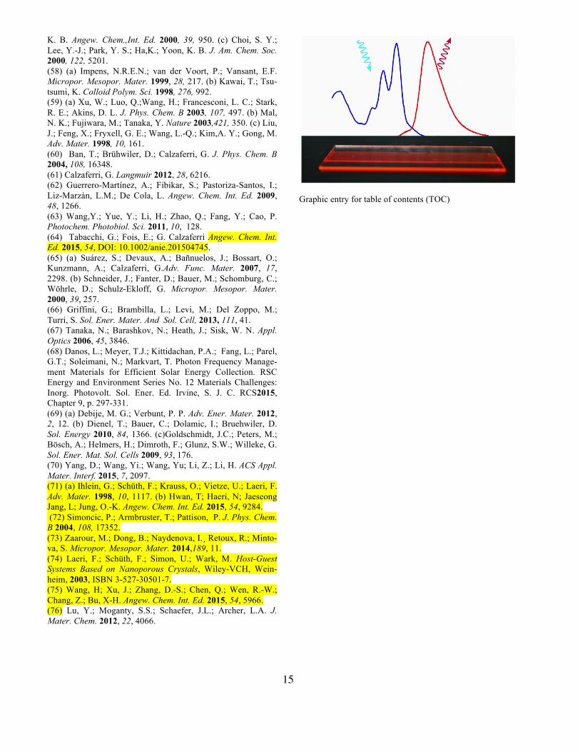
Figure 5. Photochemical stability upon exposure in an acceler-ated light stability simulator at 35 °C. Left: Optical density measured at 536 nm, scaled to 1 at 0 h irradiation time. Orange and green rectangles: two sets of experimental data of tb-DXP,HR-ZLTS.0.04,.27(0.5 IMZ+) embedded in PMMA and blue circles of tb-DXP dissolved in PMMA; dash-dot lines are calculated. Right: absorption spectra measured after 0 h (red solid), 8 h, 24 h, 48 h, 79 h, 103 h exposure. . We show in Figure 6 a photograph of a 100 µm layer of tb-DXP,HR-ZL embedded in PMMA on a glass substrate upon illumination from the top. The PMMA/ZL layer was deposited using a film applicator. A 1-butanol/acetonitrile solution (1:1) containing 20%wt of PMMA and 1%wt of the composite were used for the film application. The image illustrates the wave guiding properties of the device: the edges can be clearly seen to glow orange. Such effects of the layer are of great interest for applications as, e.g., luminescent solar concentrators (LSCs). A LCS is a waveguiding plate containing luminescent chromophores. Light falls on the face of the plate, and is ab-sorbed and subsequently re-emitted at longer wavelength. The luminescent light is trapped by total internal reflection and
Table 3. Molecules for stopcock- and surface modifica-tion.
3-(Aminopropyl) tri-ethoxysilane
(APTES)
(3-Methacryloxy-propyl)trimethoxy
silane (MPTMS)
(3-Cyanopropyl) tri-ethoxysilane
(CPTES)
(n-Octadecyl)tri-ethoxysilane
(C18TES)
1-Methyl-3-(2-(tri-ethoxysilyl)
ethyl)-1H-imidazol-3-ium
(MeImiSil) 1-Butyl-3-(2-(tri-
ethoxysilyl) ethyl)-1H-imidazol-3-ium
(BuImiSil)
Si OOH3C
OH3C O
CH3
OCH2
CH3
SiEtO
EtOEtO
CH3
Si NH2
EtOEtOEtO
Si CNEtO
EtOEtO
SiEtO
EtOEtO
NN
SiEtO
EtOEtO
NN
10
guided to the edges of the plate, where it can be, for example, collected and converted to electricity by a photovoltaic cell.68,69 It has been well understood for many years, that a major energy loss in such a device is caused by the overlap between absorp-tion and emission spectra of the chromophores.69 A way to minimize this loss is to use antenna materials such as described in this report. Absorption and emission spectra are separated by employing a large amount of an absorbing dye, and very little emitting dye. 2.5. Different Organizational Patterns of dye-ZL Compo-sites. The combinations b, b’, and c sketched in Scheme 1 are synthesized using the sequential procedure (A). This can in principle lead to antenna composites for light harvesting and transport.1,23,30 They differ in details of the photophysical prop-erties. System b” can only be synthesized if a temperature regime exists where both dyes can be inserted simultaneously so that a random distribution of the small number of acceptors results. This has so far only been realized for cationic dyes of equal size and shape which can be inserted by ion exchange from aqueous solution.34 Synthesis of b and b’ can also differ because the dyes discussed in this article have to be inserted at elevated temperatures and it is important that the dye that is inserted first survives the temperature regime needed for the insertion of the next one.
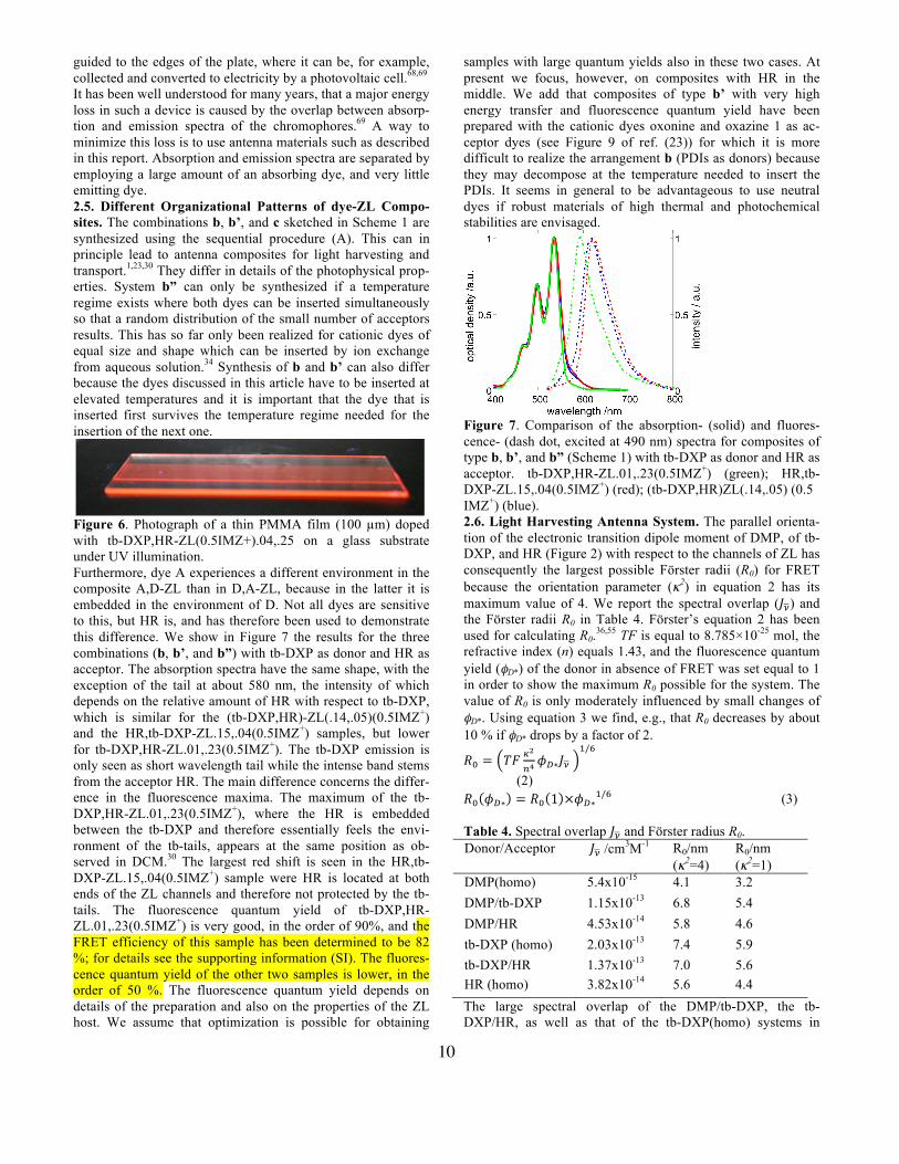
Figure 6. Photograph of a thin PMMA film (100 µm) doped with tb-DXP,HR-ZL(0.5IMZ+).04,.25 on a glass substrate under UV illumination. Furthermore, dye A experiences a different environment in the composite A,D-ZL than in D,A-ZL, because in the latter it is embedded in the environment of D. Not all dyes are sensitive to this, but HR is, and has therefore been used to demonstrate this difference. We show in Figure 7 the results for the three combinations (b, b’, and b”) with tb-DXP as donor and HR as acceptor. The absorption spectra have the same shape, with the exception of the tail at about 580 nm, the intensity of which depends on the relative amount of HR with respect to tb-DXP, which is similar for the (tb-DXP,HR)-ZL(.14,.05)(0.5IMZ+) and the HR,tb-DXP-ZL.15,.04(0.5IMZ+) samples, but lower for tb-DXP,HR-ZL.01,.23(0.5IMZ+). The tb-DXP emission is only seen as short wavelength tail while the intense band stems from the acceptor HR. The main difference concerns the differ-ence in the fluorescence maxima. The maximum of the tb-DXP,HR-ZL.01,.23(0.5IMZ+), where the HR is embedded between the tb-DXP and therefore essentially feels the envi-ronment of the tb-tails, appears at the same position as ob-served in DCM.30 The largest red shift is seen in the HR,tb-DXP-ZL.15,.04(0.5IMZ+) sample were HR is located at both ends of the ZL channels and therefore not protected by the tb-tails. The fluorescence quantum yield of tb-DXP,HR-ZL.01,.23(0.5IMZ+) is very good, in the order of 90%, and the FRET efficiency of this sample has been determined to be 82 %; for details see the supporting information (SI). The fluores-cence quantum yield of the other two samples is lower, in the order of 50 %. The fluorescence quantum yield depends on details of the preparation and also on the properties of the ZL host. We assume that optimization is possible for obtaining
samples with large quantum yields also in these two cases. At present we focus, however, on composites with HR in the middle. We add that composites of type b’ with very high energy transfer and fluorescence quantum yield have been prepared with the cationic dyes oxonine and oxazine 1 as ac-ceptor dyes (see Figure 9 of ref. (23)) for which it is more difficult to realize the arrangement b (PDIs as donors) because they may decompose at the temperature needed to insert the PDIs. It seems in general to be advantageous to use neutral dyes if robust materials of high thermal and photochemical stabilities are envisaged.
Figure 7. Comparison of the absorption- (solid) and fluores-cence- (dash dot, excited at 490 nm) spectra for composites of type b, b’, and b” (Scheme 1) with tb-DXP as donor and HR as acceptor. tb-DXP,HR-ZL.01,.23(0.5IMZ+) (green); HR,tb-DXP-ZL.15,.04(0.5IMZ+) (red); (tb-DXP,HR)ZL(.14,.05) (0.5 IMZ+) (blue). 2.6. Light Harvesting Antenna System. The parallel orienta-tion of the electronic transition dipole moment of DMP, of tb-DXP, and HR (Figure 2) with respect to the channels of ZL has consequently the largest possible Förster radii (R0) for FRET because the orientation parameter (κ2) in equation 2 has its maximum value of 4. We report the spectral overlap (𝐽!) and the Förster radii R0 in Table 4. Förster’s equation 2 has been used for calculating R0.36,55 TF is equal to 8.785×10⁻²⁵ mol, the refractive index (n) equals 1.43, and the fluorescence quantum yield (φD*) of the donor in absence of FRET was set equal to 1 in order to show the maximum R0 possible for the system. The value of R0 is only moderately influenced by small changes of φD*. Using equation 3 we find, e.g., that R0 decreases by about 10 % if φD* drops by a factor of 2.
𝑅! = 𝑇𝐹 !!
!!𝜙!∗𝐽!
!/!
(2) 𝑅! 𝜙!∗ = 𝑅! 1 ×𝜙!∗!/! (3) Table 4. Spectral overlap 𝐽! and Förster radius R0. Donor/Acceptor 𝐽! /cm3M-1 R0/nm
(κ2=4) R0/nm (κ2=1)
DMP(homo) 5.4x10⁻¹⁵ 4.1 3.2 DMP/tb-DXP 1.15x10⁻¹³ 6.8 5.4 DMP/HR 4.53x10⁻¹⁴ 5.8 4.6 tb-DXP (homo) 2.03x10⁻¹³ 7.4 5.9 tb-DXP/HR 1.37x10⁻¹³ 7.0 5.6 HR (homo) 3.82x10⁻¹⁴ 5.6 4.4 The large spectral overlap of the DMP/tb-DXP, the tb-DXP/HR, as well as that of the tb-DXP(homo) systems in
11
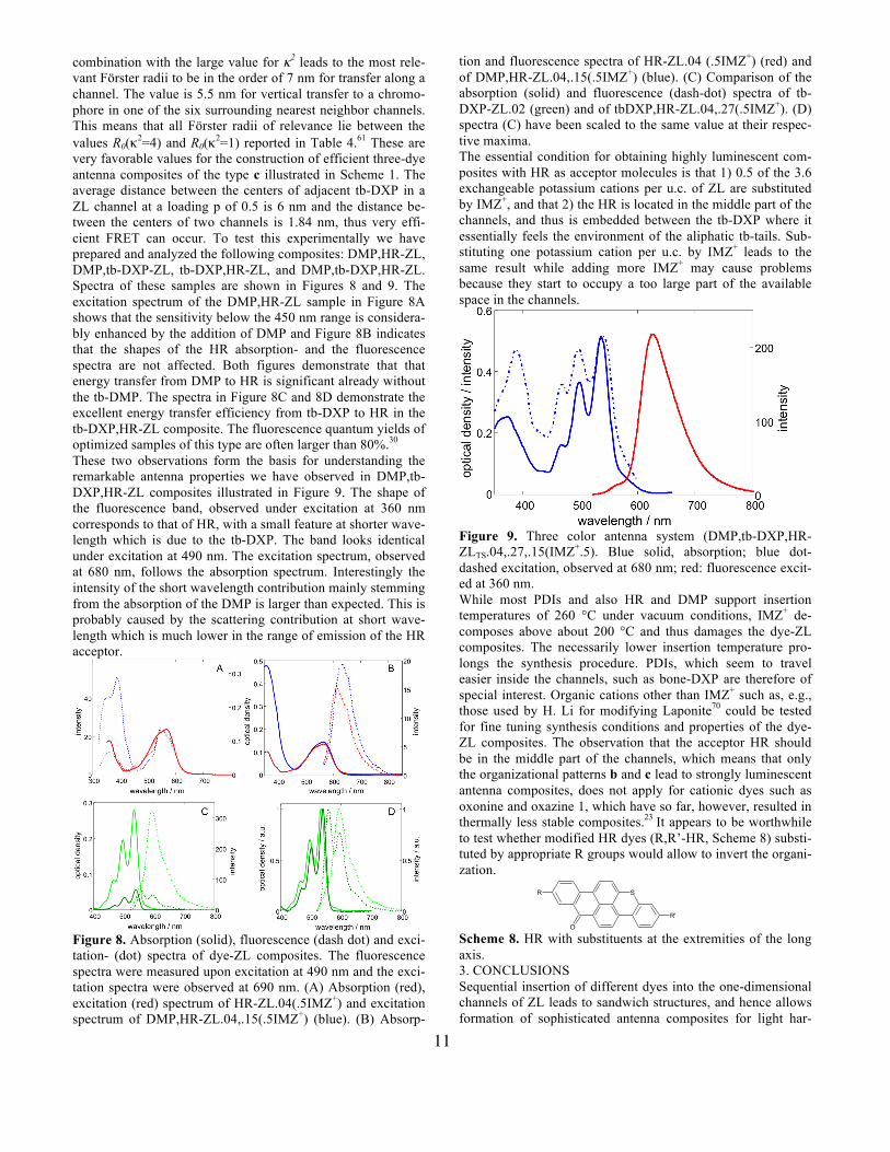
combination with the large value for κ2 leads to the most rele-vant Förster radii to be in the order of 7 nm for transfer along a channel. The value is 5.5 nm for vertical transfer to a chromo-phore in one of the six surrounding nearest neighbor channels. This means that all Förster radii of relevance lie between the values R0(κ2=4) and R0(κ2=1) reported in Table 4.61 These are very favorable values for the construction of efficient three-dye antenna composites of the type c illustrated in Scheme 1. The average distance between the centers of adjacent tb-DXP in a ZL channel at a loading p of 0.5 is 6 nm and the distance be-tween the centers of two channels is 1.84 nm, thus very effi-cient FRET can occur. To test this experimentally we have prepared and analyzed the following composites: DMP,HR-ZL, DMP,tb-DXP-ZL, tb-DXP,HR-ZL, and DMP,tb-DXP,HR-ZL. Spectra of these samples are shown in Figures 8 and 9. The excitation spectrum of the DMP,HR-ZL sample in Figure 8A shows that the sensitivity below the 450 nm range is considera-bly enhanced by the addition of DMP and Figure 8B indicates that the shapes of the HR absorption- and the fluorescence spectra are not affected. Both figures demonstrate that that energy transfer from DMP to HR is significant already without the tb-DMP. The spectra in Figure 8C and 8D demonstrate the excellent energy transfer efficiency from tb-DXP to HR in the tb-DXP,HR-ZL composite. The fluorescence quantum yields of optimized samples of this type are often larger than 80%.30 These two observations form the basis for understanding the remarkable antenna properties we have observed in DMP,tb-DXP,HR-ZL composites illustrated in Figure 9. The shape of the fluorescence band, observed under excitation at 360 nm corresponds to that of HR, with a small feature at shorter wave-length which is due to the tb-DXP. The band looks identical under excitation at 490 nm. The excitation spectrum, observed at 680 nm, follows the absorption spectrum. Interestingly the intensity of the short wavelength contribution mainly stemming from the absorption of the DMP is larger than expected. This is probably caused by the scattering contribution at short wave-length which is much lower in the range of emission of the HR acceptor.
Figure 8. Absorption (solid), fluorescence (dash dot) and exci-tation- (dot) spectra of dye-ZL composites. The fluorescence spectra were measured upon excitation at 490 nm and the exci-tation spectra were observed at 690 nm. (A) Absorption (red), excitation (red) spectrum of HR-ZL.04(.5IMZ+) and excitation spectrum of DMP,HR-ZL.04,.15(.5IMZ+) (blue). (B) Absorp-
tion and fluorescence spectra of HR-ZL.04 (.5IMZ+) (red) and of DMP,HR-ZL.04,.15(.5IMZ+) (blue). (C) Comparison of the absorption (solid) and fluorescence (dash-dot) spectra of tb-DXP-ZL.02 (green) and of tbDXP,HR-ZL.04,.27(.5IMZ+). (D) spectra (C) have been scaled to the same value at their respec-tive maxima. The essential condition for obtaining highly luminescent com-posites with HR as acceptor molecules is that 1) 0.5 of the 3.6 exchangeable potassium cations per u.c. of ZL are substituted by IMZ+, and that 2) the HR is located in the middle part of the channels, and thus is embedded between the tb-DXP where it essentially feels the environment of the aliphatic tb-tails. Sub-stituting one potassium cation per u.c. by IMZ+ leads to the same result while adding more IMZ+ may cause problems because they start to occupy a too large part of the available space in the channels.
Figure 9. Three color antenna system (DMP,tb-DXP,HR-ZLTS.04,.27,.15(IMZ+.5). Blue solid, absorption; blue dot-dashed excitation, observed at 680 nm; red: fluorescence excit-ed at 360 nm. While most PDIs and also HR and DMP support insertion temperatures of 260 °C under vacuum conditions, IMZ+ de-composes above about 200 °C and thus damages the dye-ZL composites. The necessarily lower insertion temperature pro-longs the synthesis procedure. PDIs, which seem to travel easier inside the channels, such as bone-DXP are therefore of special interest. Organic cations other than IMZ+ such as, e.g., those used by H. Li for modifying Laponite70 could be tested for fine tuning synthesis conditions and properties of the dye-ZL composites. The observation that the acceptor HR should be in the middle part of the channels, which means that only the organizational patterns b and c lead to strongly luminescent antenna composites, does not apply for cationic dyes such as oxonine and oxazine 1, which have so far, however, resulted in thermally less stable composites.23 It appears to be worthwhile to test whether modified HR dyes (R,R’-HR, Scheme 8) substi-tuted by appropriate R groups would allow to invert the organi-zation.
Scheme 8. HR with substituents at the extremities of the long axis. 3. CONCLUSIONS Sequential insertion of different dyes into the one-dimensional channels of ZL leads to sandwich structures, and hence allows formation of sophisticated antenna composites for light har-
S
O
R
R'
12
vesting, transport and trapping. The basic concepts of dye alignment in one-dimensional channel systems can in principle be applied to other zeolite framework types such as AlPO4-5 and is also applicable to mesoporous materials.71 Armbruster et al. were able to resolve the crystal structure of such a dye-Mordenite composite72 and Mintova et. al.73 stressed the im-portance of progress in zeolite synthesis to promote advanced applications. More general aspects of host-guest systems based on nanoporous crystals, including inorganic guests, has been reported.74 An important prerequisite for the integration of dye-loaded zeolites into devices, e.g. for light-harvesting, is the availability of strategies for the synthesis of crystals with vari-ous well-defined sizes and aspect ratios. There has been sub-stantial success in the field of tuning the size and aspect ratio of zeolite L crystals.17-22 Furthermore, concepts for closing the channel entrances rely on the surface chemistry of silicates, thereby so far excluding aluminophosphate zeolites such as AlPO4-5. This means that ZL remains so far the only host for which a synthesis strategy as explained in Scheme 1 has been successful. Stopcock chemistry has recently, however, also been applied to MOFs.75 Our synthesis procedures from molecules and host to compo-site materials and composite-polymer matrices, including 2- and 3-color antennas, demonstrate the important flexibility of the strategy for creating a very promising class of composites with tunable spectroscopic and photophysical properties. PDIs are important chromophores for the synthesis of artificial an-tenna systems and have therefore been considered in detail. The final step in the dye synthesis was in general a condensa-tion reaction with a perylene precursor with the appropriate amines under high temperature and catalytic conditions. There-fore, the main challenge was the preparation of the correspond-ing amines which ranges from amines that are insufficiently or not at all described in literature. - Out of the 17 PDIs tested, 11 can be easily inserted into the ZL channels at elevated tempera-tures; two enter more reluctantly, while four cannot be inserted at all. The pattern we have observed improves the phenomeno-logical understanding considerably so that results become more predictable. This enhances the possibilities for designing de-sired functionality so that controlling the substitution pattern of the inserted dyes not only allows monitoring the contact dis-tance between nearest neighbors (so that, e.g., exciton interac-tion can be switched on and off), but also fine-tuning of transport properties and of the nanochannel environment. The fact that composites bearing reasonably good characteristics can be prepared with commercial zeolite underlines the useful-ness of ZL as a host material. However, if purity, morphology, particle size, and particle size distribution matter, then it is advantageous to use well described and reproducible synthetic methods reported by several laboratories for achieving the desired result. Sealing the channel entrances so that the guests cannot exit to the environment is a prerequisite for achieving long term stability of dye-ZL composites. We have shown that a variety of different procedures can be used successfully. Plugging the channels, e.g., by means of APTES is sufficient for sealing the channels against dye leakage. APTES does not, however, prevent small molecules such as acetonitrile, ethanol, water, oxygen, and others from entering and exiting the chan-nels. As result, especially the photochemical stability of the material may be severely affected. Long-term photo-stability is an important issue for LSC devices. Sealing for smaller mole-
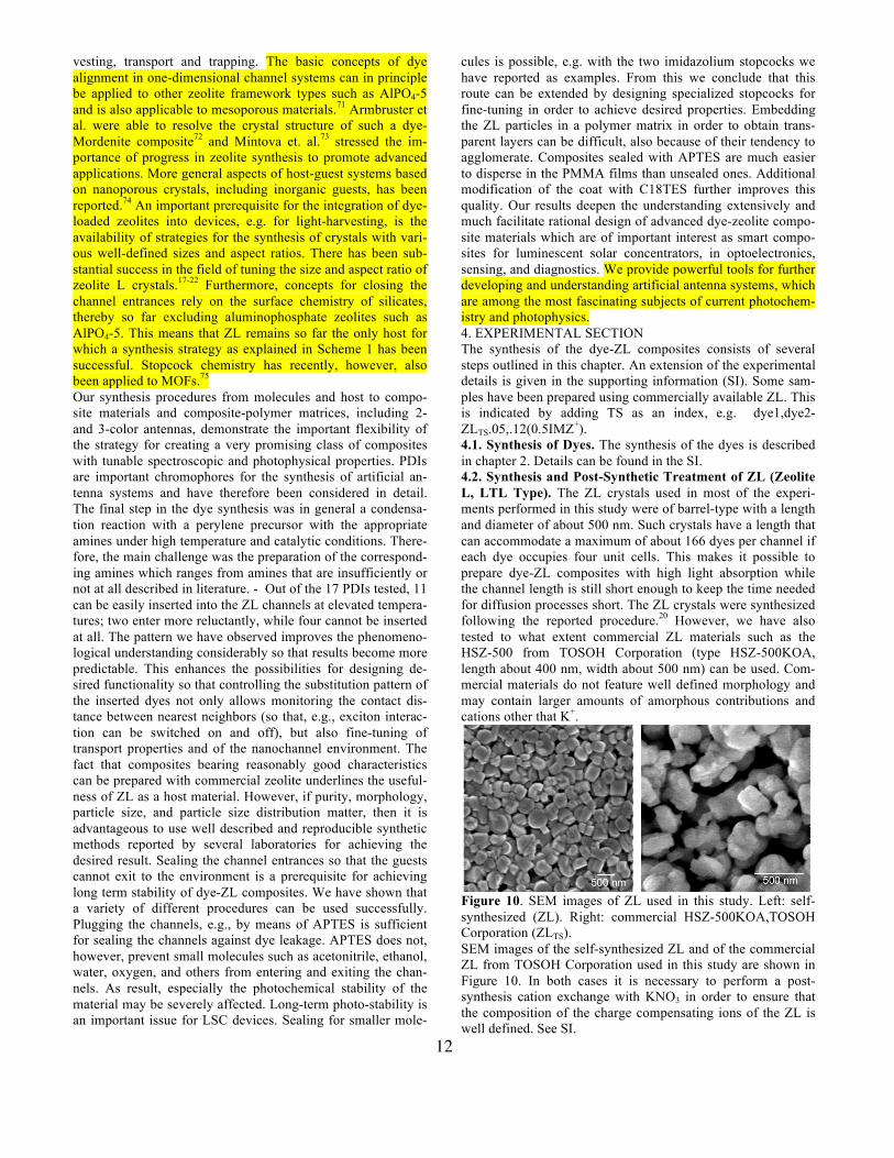
cules is possible, e.g. with the two imidazolium stopcocks we have reported as examples. From this we conclude that this route can be extended by designing specialized stopcocks for fine-tuning in order to achieve desired properties. Embedding the ZL particles in a polymer matrix in order to obtain trans-parent layers can be difficult, also because of their tendency to agglomerate. Composites sealed with APTES are much easier to disperse in the PMMA films than unsealed ones. Additional modification of the coat with C18TES further improves this quality. Our results deepen the understanding extensively and much facilitate rational design of advanced dye-zeolite compo-site materials which are of important interest as smart compo-sites for luminescent solar concentrators, in optoelectronics, sensing, and diagnostics. We provide powerful tools for further developing and understanding artificial antenna systems, which are among the most fascinating subjects of current photochem-istry and photophysics. 4. EXPERIMENTAL SECTION The synthesis of the dye-ZL composites consists of several steps outlined in this chapter. An extension of the experimental details is given in the supporting information (SI). Some sam-ples have been prepared using commercially available ZL. This is indicated by adding TS as an index, e.g. dye1,dye2-ZLTS.05,.12(0.5IMZ+). 4.1. Synthesis of Dyes. The synthesis of the dyes is described in chapter 2. Details can be found in the SI. 4.2. Synthesis and Post-Synthetic Treatment of ZL (Zeolite L, LTL Type). The ZL crystals used in most of the experi-ments performed in this study were of barrel-type with a length and diameter of about 500 nm. Such crystals have a length that can accommodate a maximum of about 166 dyes per channel if each dye occupies four unit cells. This makes it possible to prepare dye-ZL composites with high light absorption while the channel length is still short enough to keep the time needed for diffusion processes short. The ZL crystals were synthesized following the reported procedure.20 However, we have also tested to what extent commercial ZL materials such as the HSZ-500 from TOSOH Corporation (type HSZ-500KOA, length about 400 nm, width about 500 nm) can be used. Com-mercial materials do not feature well defined morphology and may contain larger amounts of amorphous contributions and cations other that K+.
Figure 10. SEM images of ZL used in this study. Left: self-synthesized (ZL). Right: commercial HSZ-500KOA,TOSOH Corporation (ZLTS). SEM images of the self-synthesized ZL and of the commercial ZL from TOSOH Corporation used in this study are shown in Figure 10. In both cases it is necessary to perform a post-synthesis cation exchange with KNO3 in order to ensure that the composition of the charge compensating ions of the ZL is well defined. See SI.
13
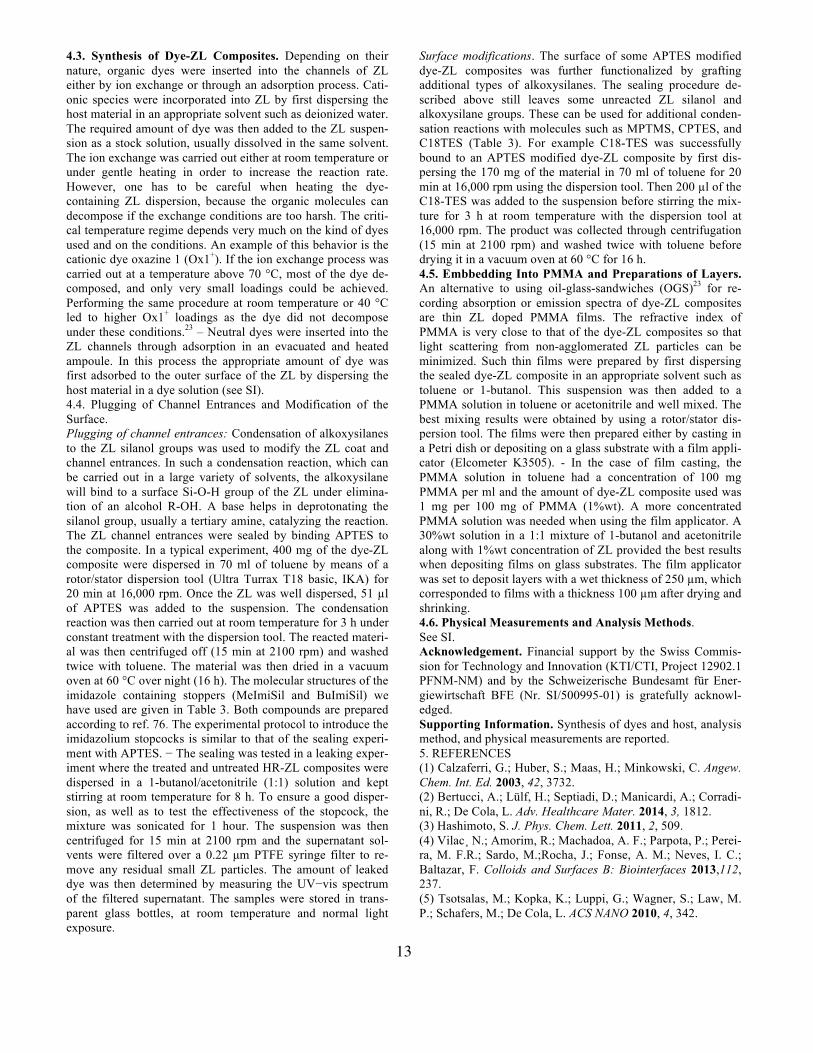
4.3. Synthesis of Dye-ZL Composites. Depending on their nature, organic dyes were inserted into the channels of ZL either by ion exchange or through an adsorption process. Cati-onic species were incorporated into ZL by first dispersing the host material in an appropriate solvent such as deionized water. The required amount of dye was then added to the ZL suspen-sion as a stock solution, usually dissolved in the same solvent. The ion exchange was carried out either at room temperature or under gentle heating in order to increase the reaction rate. However, one has to be careful when heating the dye-containing ZL dispersion, because the organic molecules can decompose if the exchange conditions are too harsh. The criti-cal temperature regime depends very much on the kind of dyes used and on the conditions. An example of this behavior is the cationic dye oxazine 1 (Ox1+). If the ion exchange process was carried out at a temperature above 70 °C, most of the dye de-composed, and only very small loadings could be achieved. Performing the same procedure at room temperature or 40 °C led to higher Ox1+ loadings as the dye did not decompose under these conditions.23 – Neutral dyes were inserted into the ZL channels through adsorption in an evacuated and heated ampoule. In this process the appropriate amount of dye was first adsorbed to the outer surface of the ZL by dispersing the host material in a dye solution (see SI). 4.4. Plugging of Channel Entrances and Modification of the Surface. Plugging of channel entrances: Condensation of alkoxysilanes to the ZL silanol groups was used to modify the ZL coat and channel entrances. In such a condensation reaction, which can be carried out in a large variety of solvents, the alkoxysilane will bind to a surface Si-O-H group of the ZL under elimina-tion of an alcohol R-OH. A base helps in deprotonating the silanol group, usually a tertiary amine, catalyzing the reaction. The ZL channel entrances were sealed by binding APTES to the composite. In a typical experiment, 400 mg of the dye-ZL composite were dispersed in 70 ml of toluene by means of a rotor/stator dispersion tool (Ultra Turrax T18 basic, IKA) for 20 min at 16,000 rpm. Once the ZL was well dispersed, 51 µl of APTES was added to the suspension. The condensation reaction was then carried out at room temperature for 3 h under constant treatment with the dispersion tool. The reacted materi-al was then centrifuged off (15 min at 2100 rpm) and washed twice with toluene. The material was then dried in a vacuum oven at 60 °C over night (16 h). The molecular structures of the imidazole containing stoppers (MeImiSil and BuImiSil) we have used are given in Table 3. Both compounds are prepared according to ref. 76. The experimental protocol to introduce the imidazolium stopcocks is similar to that of the sealing experi-ment with APTES. − The sealing was tested in a leaking exper-iment where the treated and untreated HR-ZL composites were dispersed in a 1-butanol/acetonitrile (1:1) solution and kept stirring at room temperature for 8 h. To ensure a good disper-sion, as well as to test the effectiveness of the stopcock, the mixture was sonicated for 1 hour. The suspension was then centrifuged for 15 min at 2100 rpm and the supernatant sol-vents were filtered over a 0.22 µm PTFE syringe filter to re-move any residual small ZL particles. The amount of leaked dye was then determined by measuring the UV−vis spectrum of the filtered supernatant. The samples were stored in trans-parent glass bottles, at room temperature and normal light exposure.
Surface modifications. The surface of some APTES modified dye-ZL composites was further functionalized by grafting additional types of alkoxysilanes. The sealing procedure de-scribed above still leaves some unreacted ZL silanol and alkoxysilane groups. These can be used for additional conden-sation reactions with molecules such as MPTMS, CPTES, and C18TES (Table 3). For example C18-TES was successfully bound to an APTES modified dye-ZL composite by first dis-persing the 170 mg of the material in 70 ml of toluene for 20 min at 16,000 rpm using the dispersion tool. Then 200 µl of the C18-TES was added to the suspension before stirring the mix-ture for 3 h at room temperature with the dispersion tool at 16,000 rpm. The product was collected through centrifugation (15 min at 2100 rpm) and washed twice with toluene before drying it in a vacuum oven at 60 °C for 16 h. 4.5. Embbedding Into PMMA and Preparations of Layers. An alternative to using oil-glass-sandwiches (OGS)23 for re-cording absorption or emission spectra of dye-ZL composites are thin ZL doped PMMA films. The refractive index of PMMA is very close to that of the dye-ZL composites so that light scattering from non-agglomerated ZL particles can be minimized. Such thin films were prepared by first dispersing the sealed dye-ZL composite in an appropriate solvent such as toluene or 1-butanol. This suspension was then added to a PMMA solution in toluene or acetonitrile and well mixed. The best mixing results were obtained by using a rotor/stator dis-persion tool. The films were then prepared either by casting in a Petri dish or depositing on a glass substrate with a film appli-cator (Elcometer K3505). - In the case of film casting, the PMMA solution in toluene had a concentration of 100 mg PMMA per ml and the amount of dye-ZL composite used was 1 mg per 100 mg of PMMA (1%wt). A more concentrated PMMA solution was needed when using the film applicator. A 30%wt solution in a 1:1 mixture of 1-butanol and acetonitrile along with 1%wt concentration of ZL provided the best results when depositing films on glass substrates. The film applicator was set to deposit layers with a wet thickness of 250 µm, which corresponded to films with a thickness 100 µm after drying and shrinking. 4.6. Physical Measurements and Analysis Methods. See SI. Acknowledgement. Financial support by the Swiss Commis-sion for Technology and Innovation (KTI/CTI, Project 12902.1 PFNM-NM) and by the Schweizerische Bundesamt für Ener-giewirtschaft BFE (Nr. SI/500995-01) is gratefully acknowl-edged. Supporting Information. Synthesis of dyes and host, analysis method, and physical measurements are reported. 5. REFERENCES (1) Calzaferri, G.; Huber, S.; Maas, H.; Minkowski, C. Angew. Chem. Int. Ed. 2003, 42, 3732. (2) Bertucci, A.; Lülf, H.; Septiadi, D.; Manicardi, A.; Corradi-ni, R.; De Cola, L. Adv. Healthcare Mater. 2014, 3, 1812. (3) Hashimoto, S. J. Phys. Chem. Lett. 2011, 2, 509. (4) Vilac¸ N.; Amorim, R.; Machadoa, A. F.; Parpota, P.; Perei-ra, M. F.R.; Sardo, M.;Rocha, J.; Fonse, A. M.; Neves, I. C.; Baltazar, F. Colloids and Surfaces B: Biointerfaces 2013,112, 237. (5) Tsotsalas, M.; Kopka, K.; Luppi, G.; Wagner, S.; Law, M. P.; Schafers, M.; De Cola, L. ACS NANO 2010, 4, 342.
14
(6) Cucinotta, F.; Guenet, A.; Bizzarri, C.; Mróz, W.; Botta, Ch.; Milián-Medina, B.; Gierschner, J.; De Cola, L. ChemPlu-sChem 2014, 79, 45. (7) (a) Mech, A.; Monguzzi, A.; Meinardi,F.; Mezyk, J.; Mac-chi, G.; Tubino R. J. Am. Chem. Soc. 2010, 132, 4574. (b) Cao, P.; Wang, Y.; Li, H.; Yu, X. J. Mater. Chem. 2011, 21, 2709. (c) Wen, T.; Zhang, W.; Hu, X.; He, L.; Li, H. ChemPlusChem 2013, 78, 438. (8) Mahato, R. N.; Lulf, H.; Siekman, M. H.; Kersten, S. P.; Bobbert, P. A.; de Jong, M.; De Cola, L.; van der Wiel, W. G. Science 2013, 341, 257. (9) Gigli, L.; Arletti, R.; Tabacchi, G.; Fois, E.; Vitillo, J.; Martra, G.; Agostini,G.; Quartieri,S; Vezzalini,G. J. Phys. Chem. C 2014, 118, 15732. (10) Schulte, B.; Tsotsalas, M.; Becker, M.; Studer, A.; De Cola, L. Angew. Chem. Int. Ed. 2010, 49, 6881. (11) Beierle, J. M. ; Roswanda, R.; Erne, P. M.; Coleman, A. C.; Browne, W. R.; Feringa, B. L. Part. Part.Syst. Charact. 2013, 30, 273. (12) (a) Hashimoto, S.; Hagiri, M.; Matsubara, N.; Tobita, S. Phys. Chem. Chem. Phys. 2001, 3, 5043. (b) Bussemer, B.; Dreiling, I.; Grummt, U. W.; Mohr, G. J. J. Photochem. Photo-biol., A 2009, 204, 90. (13) Schulz-Ekloff, G.; Wöhrle, D.; van Duffel, B.; Schoonhey R.A.; Micropor. Mesopor. Mater. 2002, 51, 91. (14) Sprung, Ch.; Weckhuysen, B. J. Am. Chem. Soc. 2015, 137, 1916. (15) Bossart, O.; De Cola, L.; Welter, S.; Calzaferri, G. Chem. Eur. J. 2004, 10, 5771. (16) López-Duarte, I.; Dieu, L.Q.; Dolamic, I.; Martínez-Díaz, M. V.; Torres, T.; Calzaferri, G.; Brühwiler, D. Chem. Eur. J. 2011,17, 1855. (17) Li, P.; Wang, Y.; Li, H.; Calzaferri, G. Angew. Chem. Int. Ed. 2014, 53, 2904. (18) Ohsuna, T.; Slater, B.; Gao, F.; Yu, J.; Sakamoto, Y.; Zhu, G.; Terasaki, O.; Vaughan, D.; Qiu, S.; Catlow, C. Chem. Eur. J. 2004, 10, 5031. (19) Larlus, O.; Valtchev, V. P. Chem. Mater. 2004, 16, 3381. (20) Zabala Ruiz, A.; Brühwiler, D.; Ban, T.; Calzaferri, G. Monatshefte für Chemie 2005, 136, 77. (21) Lupulescu, A. I.; Kumar, M.; Rimer, J. D. J. Am. Chem. Soc. 2013, 135, 6608. (22) Ban, T.; Takamura, M.; Morikawa, M.; Ohya, Y. Mater. Chem. Phys. 2013, 137, 1067. (23) Devaux, A.; Calzaferri, G.; Miletto, I.; Cao, P.; Belser, P.; Bru ̈hwiler, D.; Khorev, O.; Ha ̈ner, R.; Kunzmann, A. J. Phys. Chem. C 2013, 117, 23034. (24) Zabala Ruiz, A.; Li, H.; Calzaferri, G. Angew. Chem. Int Ed. 2006, 45, 5282. (25) Yoon, K.B. Acc. Chem. Res. 2007, 40, 29. (26) Cucinotta, F.; Popovic´, Z.; Weiss, E. A.; Whitesides, G. M.; De Cola, L. Adv. Mater. 2009, 21, 1142. (27) Hashimoto, S.; Samata, K.; Shoji, T.; Taira, N.; Tomita, T.; Matsuo, S. Micropor. Mesopor. Mater. 2009, 117, 220. (28) Wang, Y.; Li, H.; Feng, Y.; Zhang, H.; Calzaferri, G.; Ren. T. Angew. Chem. Int. Ed. 2010, 49,1434. (29) Fibikar, S.; Luppi, G.; Martínez-Junza, V.; Clemente-Léon, M.; De Cola, L. ChemPlusChem 2015, 80, 62. (30) Devaux, A. ; Calzaferri, G. ; Belser, P. ; Cao, P. ; Brühwi-ler, D. ; Kunzmann, A. Chem. Mater. 2014, 26, 6878.
(31) Busby, M.; Devaux, A.; Blum, C.; Subramaniam, V.; Calzaferri, G.; De Cola, L. J. Phys. Chem. C 2011, 115, 5974. (32) Calzaferri, G.; Brühwiler, D.; Meng, T.; Dieu, L.Q.; Ma-linovskii, V.L.; Häner, L.; Chem. Eur. J. 2010, 16, 11289. (33) Busby, M.; Blum, C.; Tibben, M.; Fibikar, S.; Calzaferri, G.; Subramaniam, V.; De Cola, L. J. Amer. Chem. Soc. 2008, 130, 10970. (34) Calzaferri, G.; Lutkouskaya, K. Photochem. Photobiol. Sci. 2008, 7, 879. (35) Fois, E.; Tabacchi, G.; Calzaferri, G. J. Phys. Chem. C 2010, 114, 10572. (36) (a) Förster, Th. Naturwissenschaften 1946, 6, 166. (b) Förster, Th. Ann. Physik (Leipzig) 1948, (6) 2, 55. (37) Pauchard, M.; Devaux, A.; Calzaferri G. Chem. Eur. J. 2000, 6, 3456. (38) (a) Weil, T.; Vosch, T.; Hofkens, J.; Peneva, K.; Müllen, K. Angew. Chem. Int. Ed. 2010, 49, 9068. (b) Jänsch, D.; Li, C.; Chen, L.; Wagner, M.; Müllen, K. Angew. Chem. Int. Ed. 2015, 54, 2285. (39) Bittermann, H.; Siegemund, D.; Malinovskii, V. L.; Häner, R. J. Am. Chem. Soc. 2008, 130, 15285. (40) Winiger, C. B.; Langenegger, S. M.; Calzaferri, G.; Häner, R. Angew. Chem. Int. Ed. 2015, 54, 3643. (41) (a) International Zeolite Association, http://www.iza-structure.org. (b) Baerlocher, Ch.; McCusker, L. B.; Olson, D. H.; Atlas of Zeolite Framework Types, 6th revised edition; Elsevier: Amsterdam, 2007. (42) Marcolli, C.; Calzaferri, G. Appl. Organomet. Chem. 1999,13, 213–226. (43) IMZ+: 1-ethyl-3-methyl imidazolium chloride counter ion
. (44) Myahkostupov, M.; Prusakova, V.; Oblinsky, D.G.; Scho-les, G.D.; Castellano, F.N. J. Org. Chem. 2013, 78 (17), 8634. (45) Liu J., Li Y., Li Y., Hu N., J. Appl. Polym. Sci. 2008, 109, 700. (46) Small B. L., Rios R., Fernandez E. R., Gerlach D. L., Halfen J. A., Carney M. J., Organometallics 2010, 29, 6723. (47) Ruchika, M.; Jong Min, L.; Minjung, S.; Piyush, P.; Don-gho, K.; Jeyaraman, S. Chem. Eur. J. 2014, 20, 5776. (48) Langhals H. Chem. Ber. 1985, 118, 4641. (49) Nolde, F.; Qu, J.; Kohl, C.; Pschirer, N. G.; Reuther, E.; Müllen, K. Chem. Eur. J. 2005, 11, 3959. (50) Geerts, Y.; Quante, H.; Platz, H.; Mahrt, R.; Hopmeier, M.; Bohm, A.; Müllen, K. J. Mater. Chem. 1998, 8, 2357. (51) Quante, H.; Müllen, K., Angew. Chem. Int. Ed. 1995, 34, 1323. (52) Yamamoto, T.; Morita, A.; Miyazaki, Y.; Maruyama, T.; Wakayama, H.; Zhou, Z. H.; Nakamura, Y.; Kanbara, T.; Sasa-ki, S.; Kubota, K. Macromolecules 1992, 25, 1214. (53) Bradley, W.; Pexton, F. W. J. Chem. Soc. 1954, 4432. (54) Fois, E.; Tabacchi, G.; Devaux, A.; Belser, P.; Bru ̈hwiler, D.; Calzaferri, G. Langmuir 2013, 29, 9188. (55) Calzaferri, G.; Devaux, A. Supramolecular Photochemis-try: Controlling Photochemical Processes; Ramamurthy, V., Inoue, Y., Eds.; John Wiley & Sons, Hoboken: New Jersey 2011, Chapter 9, 285-387. (56) Rademacher, A.; Märkle, S.; Langhals, H. 1982, 115, 2927. (57) (a) Park, J. S.; Lee, Y.-J.; Yoon, K. B. J. Am. Chem. Soc. 2004, 126, 1934. (b) Kulak, A.; Lee, Y.-J.; Park, Y. S.; Yoon,
N+
N
15
K. B. Angew. Chem.,Int. Ed. 2000, 39, 950. (c) Choi, S. Y.; Lee, Y.-J.; Park, Y. S.; Ha,K.; Yoon, K. B. J. Am. Chem. Soc. 2000, 122, 5201. (58) (a) Impens, N.R.E.N.; van der Voort, P.; Vansant, E.F. Micropor. Mesopor. Mater. 1999, 28, 217. (b) Kawai, T.; Tsu-tsumi, K. Colloid Polym. Sci. 1998, 276, 992. (59) (a) Xu, W.; Luo, Q.;Wang, H.; Francesconi, L. C.; Stark, R. E.; Akins, D. L. J. Phys. Chem. B 2003, 107, 497. (b) Mal, N. K.; Fujiwara, M.; Tanaka, Y. Nature 2003,421, 350. (c) Liu, J.; Feng, X.; Fryxell, G. E.; Wang, L.-Q.; Kim,A. Y.; Gong, M. Adv. Mater. 1998, 10, 161. (60) Ban, T.; Brühwiler, D.; Calzaferri, G. J. Phys. Chem. B 2004, 108, 16348. (61) Calzaferri, G. Langmuir 2012, 28, 6216. (62) Guerrero-Martínez, A.; Fibikar, S.; Pastoriza-Santos, I.; Liz-Marzàn, L.M.; De Cola, L. Angew. Chem. Int. Ed. 2009, 48, 1266. (63) Wang,Y.; Yue, Y.; Li, H.; Zhao, Q.; Fang, Y.; Cao, P. Photochem. Photobiol. Sci. 2011, 10, 128. (64) Tabacchi, G.; Fois, E.; G. Calzaferri Angew. Chem. Int. Ed. 2015, 54, DOI: 10.1002/anie.201504745. (65) (a) Suárez, S.; Devaux, A.; Bañnuelos, J.; Bossart, O.; Kunzmann, A.; Calzaferri, G.Adv. Func. Mater. 2007, 17, 2298. (b) Schneider, J.; Fanter, D.; Bauer, M.; Schomburg, C.; Wöhrle, D.; Schulz-Ekloff, G. Micropor. Mesopor. Mater. 2000, 39, 257. (66) Griffini, G.; Brambilla, L.; Levi, M.; Del Zoppo, M.; Turri, S. Sol. Ener. Mater. And Sol. Cell, 2013, 111, 41. (67) Tanaka, N.; Barashkov, N.; Heath, J.; Sisk, W. N. Appl. Optics 2006, 45, 3846. (68) Danos, L.; Meyer, T.J.; Kittidachan, P.A.; Fang, L.; Parel, G.T.; Soleimani, N.; Markvart, T. Photon Frequency Manage-ment Materials for Efficient Solar Energy Collection. RSC Energy and Environment Series No. 12 Materials Challenges: Inorg. Photovolt. Sol. Ener. Ed. Irvine, S. J. C. RCS2015, Chapter 9, p. 297-331. (69) (a) Debije, M. G.; Verbunt, P. P. Adv. Ener. Mater. 2012, 2, 12. (b) Dienel, T.; Bauer, C.; Dolamic, I.; Bruehwiler, D. Sol. Energy 2010, 84, 1366. (c)Goldschmidt, J.C.; Peters, M.; Bösch, A.; Helmers, H.; Dimroth, F.; Glunz, S.W.; Willeke, G. Sol. Ener. Mat. Sol. Cells 2009, 93, 176. (70) Yang, D.; Wang, Yi.; Wang, Yu; Li, Z.; Li, H. ACS Appl. Mater. Interf. 2015, 7, 2097. (71) (a) Ihlein, G.; Schüth, F.; Krauss, O.; Vietze, U.; Laeri, F. Adv. Mater. 1998, 10, 1117. (b) Hwan, T; Haeri, N; Jaeseong Jang, L; Jung, O.-K. Angew. Chem. Int. Ed. 2015, 54, 9284. (72) Simoncic, P.; Armbruster, T.; Pattison, P. J. Phys. Chem. B 2004, 108, 17352. (73) Zaarour, M.; Dong, B.; Naydenova, I.¸ Retoux, R.; Minto-va, S. Micropor. Mesopor. Mater. 2014,189, 11. (74) Laeri, F.; Schüth, F.; Simon, U.; Wark, M. Host-Guest Systems Based on Nanoporous Crystals, Wiley-VCH, Wein-heim, 2003, ISBN 3-527-30501-7. (75) Wang, H; Xu, J.; Zhang, D.-S.; Chen, Q.; Wen, R.-W.; Chang, Z.; Bu, X-H. Angew. Chem. Int. Ed. 2015, 54, 5966. (76) Lu, Y.; Moganty, S.S.; Schaefer, J.L.; Archer, L.A. J. Mater. Chem. 2012, 22, 4066.
Graphic entry for table of contents (TOC)

16


![Recent advances in functional supramolecular nanostructures ...msleelab.org/activities/papers/2009/[120].pdfsynthetic molecules in aqueous solution, the molecules interact with one](https://img.pdfslide.net/doc/110x75/61279cc7321e5751d01d2c22/recent-advances-in-functional-supramolecular-nanostructures-120pdf-synthetic.jpg)
![7. Supramolecular structures - Acclab h55.it.helsinki.fiknordlun/nanotiede/nanosc7nc.pdf · 7. Supramolecular structures [Poole-Owens 11.5] Supramolecular structures are large molecules](https://img.pdfslide.net/doc/110x75/5f071ded7e708231d41b63bf/7-supramolecular-structures-acclab-h55it-knordlunnanotiedenanosc7ncpdf.jpg)

![Fluorinated azobenzenes as supramolecular halogen-bonding ......halogen bonding was used to assemble molecules, leading to a variety of supramolecular architectures [8-19], as well](https://img.pdfslide.net/doc/110x75/5f98522a6666ea1f3772a60c/fluorinated-azobenzenes-as-supramolecular-halogen-bonding-halogen-bonding.jpg)