Embed Size (px)
Citation preview

TY91 / TY92 Minor Change for CS-23 Aircraft 11 July 2013
Document Control
Title: TY91 / TY92 Minor Change for CS-23 Aircraft
Identifier: SUP/TY92/001
Issue: Issue 1.0
Issue Date: 11 July 2013
Author: Andy Campbell
Authority: Andy Davis
CCB Category: 2
File Name: TY9x Minor Change for CS23 aircraft.doc
Printed on: 07/11/2013 17:17:00

TY91 / TY92 Minor Change for CS-23 Aircraft 11 July 2013 SUP/TY92/001 Issue 1.0
CONTENTS
1. PREFACE ....................................................................................................................................... 1
1.1 PURPOSE.................................................................................................................................... 1
1.2 SCOPE........................................................................................................................................ 1
1.3 CHANGES FROM PREVIOUS ISSUE .............................................................................................. 2
1.4 CHANGES FORECAST ................................................................................................................. 3
1.5 DOCUMENT CROSS-REFERENCES .............................................................................................. 3
1.5.1 Internal Documents .......................................................................................................... 3
1.5.2 External Documents ......................................................................................................... 3
1.5.3 Approval Traceability....................................................................................................... 3
1.6 ABBREVIATION AND ACRONYMS............................................................................................... 3
2. INTRODUCTION .......................................................................................................................... 4
3. CHANGE DETAILS...................................................................................................................... 5
3.1 DESCRIPTION OF CHANGE ......................................................................................................... 5
3.1.1 Stand alone VHF system................................................................................................... 5
3.1.2 Dual VHF system.............................................................................................................. 5
3.2 MECHANICAL DETAILS.............................................................................................................. 5
3.3 CONTINUED AIRWORTHINESS INSTRUCTIONS............................................................................ 6
3.4 INSTALLED EQUIPMENT SUITABILITY........................................................................................ 6
3.4.1 ETSO................................................................................................................................. 6
3.4.2 Environmental .................................................................................................................. 6
3.5 DRAWINGS ................................................................................................................................ 9
3.5.1 Front Panel Cut-out.......................................................................................................... 9
3.5.2 Mounting tray fixing and overall dimensions................................................................. 10
3.6 ELECTRICAL LOAD ANALYSIS ................................................................................................. 10
3.7 TESTING DETAILS.................................................................................................................... 11
3.8 FLIGHT MANUAL/POH AMENDMENTS..................................................................................... 11
3.9 RADIO STATION LICENCE ........................................................................................................ 11
4. PREPERATION........................................................................................................................... 12
4.1 EQUIPMENT AND TOOLS REQUIRED.......................................................................................... 12
4.2 AIRCRAFT VOLTAGE ............................................................................................................... 12
4.3 TC90 LOCATION ..................................................................................................................... 12
4.3.1 Accessibility .................................................................................................................... 12
4.3.2 TC90 Display Visibility .................................................................................................. 12
______________________
Trig Avionics Limited Confidential Page i

TY91 / TY92 Minor Change for CS-23 Aircraft 11 July 2013 SUP/TY92/001 Issue 1.0
______________________
Trig Avionics Limited Confidential ii
4.3.3 Panel Location................................................................................................................ 12
4.4 TY91/92 POSITION.................................................................................................................. 13
4.5 HEADSET CONNECTIONS ......................................................................................................... 13
4.6 PUSH TO TALK (PTT) SWITCHES ............................................................................................. 14
4.7 PRE-TEST EXISTING INSTALLATION......................................................................................... 14
4.8 PROTECTIVE DEVICES .............................................................................................................. 14
4.9 WIRING ................................................................................................................................... 15
4.9.1 Power and Ground ......................................................................................................... 15
4.9.2 Audio Wiring .................................................................................................................. 15
4.9.3 Wire Routing................................................................................................................... 16
4.9.4 Inspect the General Wiring............................................................................................. 16
4.10 VHF ANTENNA ....................................................................................................................... 16
5. ACCOMPLISHMENT INSTRUCTIONS ................................................................................. 18
5.1 TY91/92 INSTALLATION ......................................................................................................... 18
5.1.1 Remove Existing Radio................................................................................................... 18
5.1.2 Installing TY91/92 Radio................................................................................................ 18
5.1.3 Installing the TC90 controller ........................................................................................ 18
5.1.4 Wiring Loom................................................................................................................... 18
5.1.5 Com1/Com2 Switching ................................................................................................... 18
5.2 WIRING DIAGRAMS ................................................................................................................. 19
Figure 1 - Typical TY91/92 System Interconnect ........................................................................... 20
Figure 2 - Dual VHF system using an Audio Panel ....................................................................... 21
Figure 3 - Dual VHF system using a standalone Intercom panel .................................................. 22
5.3 ANTENNA CONNECTION .......................................................................................................... 23
5.4 POST INSTALLATION CHECKS.................................................................................................. 23
5.4.1 Continuity Check ............................................................................................................ 23
5.4.2 Secure Looms.................................................................................................................. 23
5.4.3 Initial Power On ............................................................................................................. 23
5.4.4 Isolation check................................................................................................................ 23
5.4.5 Setup ............................................................................................................................... 23
5.5 TEST........................................................................................................................................ 23
5.5.1 Equipment Function ....................................................................................................... 23
5.5.2 Interference Effects......................................................................................................... 23
5.5.3 Ground Test .................................................................................................................... 24
5.5.4 Flight Test....................................................................................................................... 24
6. COMPLIANCE STATEMENT .................................................................................................. 25

TY91 / TY92 Minor Change for CS-23 Aircraft 11 July 2013 SUP/TY92/001 Issue 1.0
______________________
Trig Avionics Limited Confidential iii
7. APPENDIX 1 ................................................................................................................................ 27
THIS DOCUMENT IS CONFIDENTIAL AND CONTAINS COMMERCIALLY SENSITIVE INFORMATION TO TRIG AVIONICS LTD AND PARTNER COMPANIES. THE CONTENTS OF THIS DOCUMENT ARE TO BE KEPT CONFIDENTIAL AND ARE NOT TO BE DISCLOSED TO THIRD PARTIES WITHOUT THE PRIOR WRITTEN CONSENT OF TRIG AVIONICS LTD.

TY91 / TY92 Minor Change for CS-23 Aircraft 11 July 2013 SUP/TY92/001 Issue 1.0
______________________
Trig Avionics Limited Page 1
1. Preface
1.1 Purpose
To document the Minor Change to replace a Mode A/C transceiver with a Trig Avionics TY91/TY92 Mode S transceiver.
1.2 Scope
This Minor Change applies to unpressurised single engine piston aeroplane.
The applicable aircraft are:
Piper PA-38-112 TCDS USA A18SO
Cessna 150 TCDS 3A19
Cessna 150A TCDS 3A19
Cessna 150B TCDS 3A19
Cessna 150C TCDS 3A19
Cessna 150D TCDS 3A19
Cessna 150E TCDS 3A19
Cessna 150F TCDS 3A19
Cessna 150G TCDS 3A19
Cessna 150H TCDS 3A19
Cessna 150J TCDS 3A19
Cessna 150K TCDS 3A19
Cessna A150K TCDS 3A19
Cessna 150L TCDS 3A19
Cessna A150L TCDS 3A19
Cessna 150M TCDS 3A19
Cessna A150M TCDS 3A19
Cessna 152 TCDS 3A19
Cessna A152 TCDS 3A19
Cessna F150F TCDS A13EU
Cessna F150G TCDS A13EU
Cessna F150H TCDS A13EU
Cessna F150J TCDS A13EU
Cessna F150K TCDS A13EU
Cessna F150L TCDS A13EU
Cessna F150M TCDS A13EU
Cessna F152 TCDS A13EU

TY91 / TY92 Minor Change for CS-23 Aircraft 11 July 2013 SUP/TY92/001 Issue 1.0
______________________
Trig Avionics Limited Page 2
Cessna FA150K TCDS A13EU
Cessna FA150L TCDS A13EU
Cessna FA150M TCDS A13EU
Cessna FA152 TCDS A13EU
Cessna FRA152 TCDS A13EU
Cessna FRA150L TCDS A13EU
Cessna FRA150M TCDS A13EU
American Champion 7AC TCDS A-759
American Champion 7ACA TCDS A-759
American Champion S7AC TCDS A-759
American Champion 7BCM TCDS A-759
American Champion 7CCM TCDS A-759
American Champion S7CCM TCDS A-759
American Champion 7DC TCDS A-759
American Champion S7DC TCDS A-759
American Champion 7EC TCDS A-759
American Champion S7EC TCDS A-759
American Champion 7ECA TCDS A-759
American Champion 7FC TCDS A-759
American Champion 7GC TCDS A-759
American Champion 7GCA TCDS A-759
American Champion 7GCAA TCDS A-759
American Champion 7GCB TCDS A-759
American Champion 7GCBA TCDS A-759
American Champion 7GCBC TCDS A-759
American Champion 7HC TCDS A-759
American Champion 7JC TCDS A-759
American Champion 7KC TCDS A-759
American Champion 7KCAB TCDS A-759
American Champion 8KCAB TCDS A21CE
American Champion 8GCBC TCDS A21CE
This Minor Change applies to both US manufactured and French manufactured aircraft.
1.3 Changes from Previous Issue
None, this is the first issue

TY91 / TY92 Minor Change for CS-23 Aircraft 11 July 2013 SUP/TY92/001 Issue 1.0
______________________
Trig Avionics Limited Page 3
1.4 Changes Forecast
None.
1.5 Document Cross-References
1.5.1 Internal Documents
00839-00 TY91/TY92 Installation Manual Issue AC
00840-00 TY91/TY92 Operating Manual Issue AA
DEV/TY92/006 TY92 Declaration of Design Performance Issue 2.0
DEV/TC90/008 TC90 Declaration of Design Performance Issue 2.0
1.5.2 External Documents
CS-23 (Amdt 3) Certification Specifications for Normal, Utility, Aerobatic, and Commuter Category Aeroplanes
EASA
CAP747 Mandatory Requirements for Airworthiness CAA
ED-23C MOPS for airborne VHF Receiver - Transmitter Eurocae
1.5.3 Approval Traceability
Not applicable
1.6 Abbreviation and Acronyms
The following abbreviations and acronyms are used in this document:
AFM Aircraft Flight Manual
DC Direct Current
DDP Declaration of Design Performance
EASA European Aviation Safety Agency
ETSO European Technical Standards Order
MOPS Minimum Operational Performance Standard
POH Pilots Operating Handbook
PTT Push To Talk
VHF Very High Frequency

TY91 / TY92 Minor Change for CS-23 Aircraft 11 July 2013 SUP/TY92/001 Issue 1.0
______________________
Trig Avionics Limited Page 4
2. Introduction
The TY91/TY92 VHF radio system is an ED-23C compliant class C (25 kHz offset carrier) and class E (8.33 kHz single carrier) VHF radio. The TY91 has a nominal power output of 6 watts, and meets the power output requirements for Class 4 and Class 6. The TY92 has a nominal power output of 16 watts, and meet the power output requirements for Class 3 and Class 5. The TY91/TY92 is certified to ETSO 2C169a, and TSO C169a.
The TY91 and TY92 VHF radios are controlled using a separate front panel controller, called the TC90. This allows the radio to be mounted separately from the instrument panel, and reduces the amount of panel space taken by the VHF radio. The TC90 is certified to ETSO 2C169a, and TSO C169a.
The TY91 runs from either 14 volt nominal or 28 volt nominal DC power supply with no configuration changes required. The TY92 requires 28 volt nominal supply.
This minor change describes the process of installing a TY91 or TY92. The TY91 or TY92 can be installed as a standalone VHF communication system or as part of a dual VHF communications system.

TY91 / TY92 Minor Change for CS-23 Aircraft 11 July 2013 SUP/TY92/001 Issue 1.0
______________________
Trig Avionics Limited Page 5
3. Change Details
3.1 Description of Change
The TY91 or TY92 VHF radio can be fitted as a standalone system or as part of a dual communication system.
3.1.1 Stand alone VHF system
This change involves removing any existing VHF radio and replacing it with a Trig Avionics TY91 or TY92 VHF transceiver.
The processes involved in the change includes pre-testing of the installation; verification of the suitability of the existing power supply wiring; installing the TC90 controller and the TY91/TY92 transceiver; transceiver commissioning; and post-installation testing. These processes are described in detail in the accomplishment instructions in this document.
The existing transceiver mounting tray will need to be removed and a new panel installed to mount the controller or install a blanking panel if a conventional 57mm instrument cut-out will be used. The connectors will need to be replaced. The existing antenna and circuit breaker will be re-used.
If there is no existing VHF transceiver then the processes involved in installing a TY91/92 will include making a new wiring loom, installing headphone and microphone jacks, fitting the TC90 controller to the aircraft panel, installing a new antenna and selecting and fitting an appropriate circuit protective device.
3.1.2 Dual VHF system
This change involves installing the TY91 or TY92 VHF radio as part of a dual VHF transceiver system. The operator will require a method of switching between COM 1 and COM 2 to allow a transmission on either radio. This is most commonly achieved by using an audio panel but some installations may have to install additional switches in the cockpit. A new antenna may also need to be installed.
If the dual system relies on an intercom which is integrated into one of the radios, the microphone switching becomes complicated and further system design will be required. As such, these instructions do not cover this type of installation.
These instructions will only cover dual installations that have either an audio panel or standalone intercom system already installed.
The position of the TC90 must still be located in the aircraft panel where it can be easily read and controlled when the aircraft is being flown by a single person.
3.2 Mechanical Details
The TY91/TY92 uses a TC90 head unit to control the transceiver, it has a combination of knobs and press buttons to change frequencies and control the functions of the unit. The active and standby frequencies are displayed on the screen and icons are displayed on the left hand side to indicate when the radio is transmitting or receiving. The panel location should allow the screen to be visible to the pilot and have easy access to the knobs and buttons.
The TY91/TY92 is compatible with any TSO approved VHF antenna.
The TY91/TY92 combined with the TC90 has a total weight of 440 grams. The effect on weight and balance of the aircraft will be small due to the low weight of the transceiver equipment. After the installation a weight and balance check should be calculated or performed in accordance with the

TY91 / TY92 Minor Change for CS-23 Aircraft 11 July 2013 SUP/TY92/001 Issue 1.0
______________________
Trig Avionics Limited Page 6
manufactures instructions.
3.3 Continued Airworthiness Instructions
Other than for periodic functional checks required by the regulations, the TY91/TY92 VHF transceiver has been designed and manufactured to allow “on condition maintenance”. This means that there are no periodic service requirements necessary to maintain continued airworthiness, and no maintenance is required until the equipment does not properly perform its intended function. When service is required, a complete performance test as detailed in section 5.4 of these instructions should be accomplished following any maintenance action.
3.4 Installed Equipment Suitability
3.4.1 ETSO
The TY91 is certified to ETSO 2C169a and ETSO 2C128
The TY92 is certified to ETSO 2C169a and ETSO 2C128
The TC90 is certified to ETSO 2C169a
3.4.2 Environmental
The environmental testing conducted for the TY91/TY92 and TC90 is appropriate for this installation.
Key aspects of the TY91 and TY92 environmental qualification are summarised here:
DO-160F reference Qualification Applicability
Temperature & Altitude Category A2 and C1 Equipment intended for installation in a partially controlled temperature but pressurised location and installed is a non-pressurised but controlled temperature location.
Loss of Cooling +70C without cooling air Forced air cooling not required.
Temperature Variation Category B For a non temperature controlled or partially temperature controlled internal section of the aircraft.
Humidity Category A Standard humidity environment.
Operational Shock & Crash Safety
Category B type 5 Equipment generally installed in fixed-wing aircraft or helicopters, VLA’s and sailplanes tested for standard operational shock and crash safety.
Vibration Aircraft zone 2; type 3, 4, 5 to category S level M, type 1 (Helicopters) to category U level G
Single engine fixed wing reciprocating or turboprop. Multi engine less than 5700Kg. Helicopters, reciprocating and turbojet engines. Equipment fitted to instrument panel, console or equipment rack.
Magnetic Effect Category Z Equipment and or its connecting cable harness may be mounted within 0.3m of magnetic compass. All verified during ETSO environmental qualification testing.
Power Input Category BX DC equipment intended for use on aircraft electrical system supplied by engine driven alternator or generator, where a battery of significant capacity is on the DC bus at all times.

TY91 / TY92 Minor Change for CS-23 Aircraft 11 July 2013 SUP/TY92/001 Issue 1.0
______________________
Trig Avionics Limited Page 7
Voltage Spike Category B Installation where a lower standard of protection is acceptable.
Audio Susceptibility Category B DC equipment intended for use on aircraft electrical system supplied by engine drive alternator or generator, where a battery of significant capacity is on the DC bus at all times.
Induced Signal Susceptibility
Category AC Equipment intended for operation where interference-free operation is desirable and installed on aircraft whose primary power is constant frequency or DC.
RF Susceptibility Category TT Specified in the HIRF rules; representative of the internal EMI environment from aircraft equipment.
RF Emission Category B Basic emission control.
Key aspects of the TC90 environmental qualification are summarised here:
DO-160F reference Qualification Applicability
Temperature & Altitude Category A4 and C4 Equipment intended for installation in a controlled temperature and pressurized location. Equipment intended for installation in non-pressurised and non- controlled temperature location.
Loss of Cooling +70C without cooling air Forced air cooling not required.
Temperature Variation Category A Equipment external to the aircraft or internal to the aircraft.
Humidity Category A Standard humidity environment.
Operational Shock & Crash Safety
Category B type 5 Equipment generally installed in fixed-wing aircraft or helicopters, tested for standard operational shock and crash safety.
Vibration Aircraft zone 2; type 3, 4, 5 to category S level M, type 1 (Helicopters) to category U level G
Single engine fixed wing reciprocating or turboprop. Multi engine less than 5700Kg. Helicopters, reciprocating and turbojet engines. Equipment fitted to instrument panel, console or equipment rack.
Magnetic Effect Category Z Equipment and or its connecting cable harness may be mounted within 0.3m of magnetic compass. All verified during ETSO environmental qualification testing.
Power Input Category X Equipment identified as Category X – no test required
Voltage Spike Category X Equipment identified as Category X – no test required
Audio Susceptibility Category X Equipment identified as Category X – no test required
Induced Signal Susceptibility
Category BC Equipment intended for operation in systems where interference would be controlled to a tolerable level and is installed on aircraft whose

TY91 / TY92 Minor Change for CS-23 Aircraft 11 July 2013 SUP/TY92/001 Issue 1.0
______________________
Trig Avionics Limited Page 8
primary power is constant frequency or DC.
RF Susceptibility Category TT Specified in the HIRF rules; representative of the internal EMI environment from aircraft equipment.
RF Emission Category M Equipment and interconnected wiring located in areas where apertures are electro-magnetically significant and not directly in view of radio receivers antenna.
In each case the environmental qualification is appropriate to the installation in the instrument panel of a light piston engine aircraft with a DC electrical system.
TY91 / TY92 Minor Change for CS-23 Aircraft 11 July 2013 SUP/TY92/001 Issue 1.0
______________________
Trig Avionics Limited Page 9
3.5 Drawings
3.5.1 Front Panel Cut-out
The front panel controller can be fitted to either the compact mounting hole or a conventional 57mm (2¼ inch) instrument cut-out. The compact mounting is a truncated 58 mm opening; please note that the mounting screws are NOT in the same location for the two options.
All dimensions in millimetres. The drawing is not to scale.
(Drawing A)

TY91 / TY92 Minor Change for CS-23 Aircraft 11 July 2013 SUP/TY92/001 Issue 1.0
______________________
Trig Avionics Limited Page 10
3.5.2 Mounting tray fixing and overall dimensions
All dimensions in millimetres. The drawing is not to scale
(Drawing B)
3.6 Electrical Load Analysis
Existing VHF transceivers draw typically 0.27 Amp up to 1.0 Amp when receiving and 2 Amp up to 6 Amp when transmitting. These figures are based on a 14v DC supply.
The TY91 draws typically 0.2 Amp from a 14v DC power supply in receive, with currents of around 2 Amp when transmitting. On 28V supplies the currents are lower.
The TY92 can only be powered from a 22 to 33v DC power supply and draws typically 0.13 Amp in receive with currents of around 2.5 Amp when transmitting.
Since the current taken by the TY91/TY92 is of similar or less than the transceiver it is replacing, any systems that were properly sized to support an existing transceiver will be adequate to support the TY91/TY92.
On new TY91/92 installations, the wiring and circuit breaker rating to be used are specified in the accomplishment instructions.
On the same basis, it can be concluded that the 30 minute battery requirement of CAP747 GR6 will also be satisfied.
On a dual radio installation the circuit breakers and electrical supply will be separate so that a failure in one radio system will not result in both radio’s failing as per CAP747 GR18.

TY91 / TY92 Minor Change for CS-23 Aircraft 11 July 2013 SUP/TY92/001 Issue 1.0
______________________
Trig Avionics Limited Page 11
3.7 Testing Details
The test procedure is based on the installation test guidelines in ED-23C, the MOPS for airborne VHF transceivers.
3.8 Flight manual/POH Amendments
No AFM amendments are required as part of this Minor Change. A pilot operating booklet is provided (reference 00840-00) with the TY91/TY92 and this should be made available to the flight crew.
3.9 Radio Station Licence
Installation of this transceiver may require a new or updated aircraft radio licence. For UK registered aircraft the change needs to be reported to the Directorate of Airspace Policy on a Form DAP1902. For other European registered aircraft the relevant national authority should be contacted.
TY91 / TY92 Minor Change for CS-23 Aircraft 11 July 2013 SUP/TY92/001 Issue 1.0
______________________
Trig Avionics Limited Page 12
4. Preparation
4.1 Equipment and tools required
You will need an aviation headset, aircraft aluminium, the TY91/TY92 install kit and standard avionics workshop tooling.
4.2 Aircraft Voltage
Ensure the aircraft voltage is correct for the desired radio.
For TY91 radio’s the aircraft voltage must be 11 – 33 volts.
For TY92 radio’s the aircraft voltage must be 22 – 33 volts.
4.3 TC90 Location
4.3.1 Accessibility
Ensure the TC90 controller is installed so that the control knobs and buttons are readily accessible from the pilot’s normal seated position. The operator should have a clear an unobstructed view of the TC90 display.
4.3.2 TC90 Display Visibility
The TC90 LCD has a reflective back and a constant backlight to allow it to be easily read in both direct sunlight and low lighting conditions. The TC90 is recommended to be within a viewing angle of 40 degrees in the vertical plane and 50 degrees in the horizontal plane to ensure the full display can be seen.
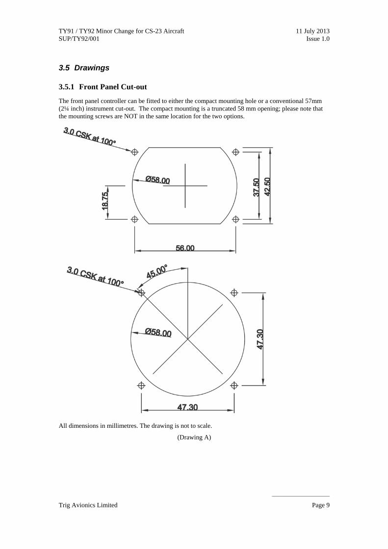
4.3.3 Panel Location
Choose a suitable location for the TC90 controller that meets the following criteria:
The TC90 must be located in a position where it can be operated when the aircraft is being flown by a single person.
If any of the existing displays need to be re-positioned to accommodate the additional TC90, you must ensure that the new positions of these do not contravene CS.23-1321 (arrangement and visibility)
Example location – Left of central column Example Location – Central column

TY91 / TY92 Minor Change for CS-23 Aircraft 11 July 2013 SUP/TY92/001 Issue 1.0
______________________
Trig Avionics Limited Page 13
4.4 TY91/92 Position .4 TY91/92 Position
The TY91/92 remote unit can be installed in any orientation as long as it is secured with the dedicated mounting tray (part number 00667-00). The mounting tray must be secured to a solid piece of structure in a suitable location that meets the following criteria:
The TY91/92 remote unit can be installed in any orientation as long as it is secured with the dedicated mounting tray (part number 00667-00). The mounting tray must be secured to a solid piece of structure in a suitable location that meets the following criteria:
Does not interfere with any primary flying controls. Does not interfere with any primary flying controls.
Will not be subject to any damage or displacement due to person entering/exiting the aircraft. Will not be subject to any damage or displacement due to person entering/exiting the aircraft.
Allows a suitable routing for any interconnecting wiring. Allows a suitable routing for any interconnecting wiring.
Will not be subject to adverse weather conditions such as rain, snow or ice. Will not be subject to adverse weather conditions such as rain, snow or ice.
Example Location – Access Panel
Example Location – Rear bulk head
4.5 Headset Connections
If you are utilising existing headset connections you should check the serviceability as per section 4.7.
If you are installing a new headset connection then you should choose a suitable location that allows a

TY91 / TY92 Minor Change for CS-23 Aircraft 11 July 2013 SUP/TY92/001 Issue 1.0
______________________
Trig Avionics Limited Page 14
headset to be connected easily without the need to extend the headset cables. Traditionally this will be at the bottom of the aircraft panel adjacent to the appropriate seating position.
Typical headset jack position
4.6 Push to Talk (PTT) Switches
If you are utilising the existing PTT switches then you should check the serviceability as per section 4.7.
A new PTT installation should use a momentary push switch mounted on the aircraft yoke.
4.7 Pre-test Existing Installation
If the TY91/TY92 installation is gong to utilise any existing aircraft components such as wiring, coax or antenna then these should be checked for serviceability before proceeding with the installation. Pay particular attention to the following:
Wiring – Ensure that screened cable has been used where appropriate. Using unscreened wiring may lead to unwanted interference from other equipment such as the transponder, strobe lights or ignition system.
Antenna and coax cable – Ensure the antenna, antenna cable and connectors are in good condition and of a suitable type. RG400 is recommended as a minimum for the antenna coax cable and the antenna VSWR should not exceed 3:1. Having an antenna system with a VSWR greater than 3:1 will cause a large drop in output power and severely minimise the range of the radio transmissions.
PTT switches – Ensure the existing PTT switches are in good condition and operating correctly.
Headset connections – Ensure the existing headphone and microphone jacks are in good condition and working correctly.
If there is a problem with the existing installation, changing the radio will not cure this problem and will simply transfer to your new TY921/TY92 installation. It is a good idea to check at this stage and update any wiring to save time and frustration later.
4.8 Protective devices
On a single TY91/92 radio installation the live power supply must be protected by a 5 amp circuit breaker. If you are utilising an existing circuit breaker please refer to section 4.9 for suitability.
For dual radio installations the live power supply to each radio must be protected by separate circuit breakers so that a failure in one radio does not affect the performance of the other radio. This is required as part of CAP 747 GR18.

TY91 / TY92 Minor Change for CS-23 Aircraft 11 July 2013 SUP/TY92/001 Issue 1.0
______________________
Trig Avionics Limited Page 15
5 Amp Circuit breaker
4.9 Wiring
4.9.1 Power and Ground
If you are replacing a radio system with the TY91/TY92 and utilising the same power and ground, check the following:
Verify that the circuit breaker is in satisfactory condition and is rated at 5 Amps.
Note: The circuit breaker rating is determined by the type of wiring used. A higher rated circuit breaker can be used as long as the wire size can handle the current. The circuit breaker must not be less than 5 amps to avoid nuisance tripping. For more information you can refer to FAA AC 43.13-1B [chapter 11]
Ensure the existing live wiring is in good condition and sized correctly. For a 5 Amp circuit breaker, the power and ground wires are recommended to be a minimum of 20 AWG.
Ensure the ground wire is actually connected to ground. It sounds obvious but some installations can rely on the aircraft chassis or mounting trays for a connection to ground, if any of this is disturbed during the installation the ground connection may be broken. You should physically trace the wire to check if it is connected to ground or use a multimeter to perform a connection test.
If the TY91/TY92 is a new installation then you should check there is space in the panel to fit the addition 5 Amp circuit breaker required. All power and ground wires should be of the size and type detailed in the wiring diagrams.
4.9.2 Audio Wiring
Audio wiring is often overlooked and a bad installation can cause constant interference and clicks from other aircraft systems which can cause pilot fatigue. Planning good cable routes and using the correct type of wiring will give a quiet and comfortable radio system.
Every un-shielded wire can act as a small antenna and pick up any stray RF transmissions, routing that RF into your audio system giving the potential for unwanted interference.
Good audio wiring practices to prevent interference:
Use shielded wire on quiet audio lines. There is no limit to the amount of shielded wire you can use but it is expensive and it is not necessary on all wiring. Quiet audio lines such as the

TY91 / TY92 Minor Change for CS-23 Aircraft 11 July 2013 SUP/TY92/001 Issue 1.0
______________________
Trig Avionics Limited Page 16
microphone inputs must be shielded.
Route wiring looms away from high noise environments. Whilst this is not always practical on smaller aircraft, keeping the audio wiring away from ignition wires, engines and transmitting antennas will help reduce the amount of RF exposure.
4.9.3 Wire Routing
Care must be taken to ensure surface damage does not occur to the wires during installation and that all wire looms are appropriately secured to prevent damage during its installed life. Ensure the loom does not chafe on any parts of the aircraft or interfere with any moving parts especially if you are using thin walled insulated wire to save on weight, such as MIL-22759/16, 17, 18 or 19.
4.9.4 Inspect the General Wiring
Inspect any existing wiring for the general condition and gauge. The power wires should be AWG 20 or heavier; the other signal wires carry only light currents and may be any gauge appropriate to the mechanical environment.
4.10 VHF Antenna
If you are utilising an existing antenna:
Trace and identify the existing VHF antenna.
Check the condition of the antenna, including the attachment to the airframe. It is important that the ground plane of the antenna is correctly bonded to the aircraft skin. The antenna should be in a vertical orientation, as clear as possible from other antennae and from airframe obstacles and protrusions, such as landing gear.
The antenna VSWR should be < 2:1 and should not be greater than 3:1 to avoid a degraded output power performance; an inline wattmeter can be used to measure the VSWR. If the VSWR is suspect at this stage the antenna and/or the coax cabling should be checked.
If you are installing a new antenna you should follow the manufacturer’s instructions and pay particular attention to the following:
Ensure the antenna is a 50 Ohm, vertically polarised VHF antenna
A Com 1 antenna should be mounted on the top of the aircraft
A Com 2 antenna can be mounted on the top or the bottom of the aircraft. Mounting on the top of the airframe is preferable and should be about 1 metre from the COM 1 antenna to avoid interference. If mounting on the bottom of the aircraft then a bent whip antenna may be suitable to provide sufficient ground clearance, although signal obstruction from the landing gear or flaps should be taken into account when choosing the antenna location.
Ensure the antenna position is not within:
o 0.6 metres from a GPS antenna
o 1.0 metre from other VHF antenna’s
o As far as practicable from ELT antenna’s which could cause interference on certain frequencies
Try to avoid locating the antenna anywhere near the engine exhaust or ignition system to reduce any interference effects.

TY91 / TY92 Minor Change for CS-23 Aircraft 11 July 2013 SUP/TY92/001 Issue 1.0
______________________
Trig Avionics Limited Page 17
Existing COM1 antenna
Proposed COM2 antenna position
Piper PA38
Com 1 antenna position
Com 2 antenna position
Cessna 150
Proposed COM2 antenna position
Existing COM1 antenna
American Champion

TY91 / TY92 Minor Change for CS-23 Aircraft 11 July 2013 SUP/TY92/001 Issue 1.0
______________________
Trig Avionics Limited Page 18
5. Accomplishment Instructions
5.1 TY91/92 Installation
5.1.1 Remove Existing Radio
If you are replacing an existing VHF radio then this should be removed. Identify any existing wiring that is going to be reused and check for suitability as previously described. Replace any suspect, damaged or unsuitable wiring.
If the TC90 is not going to be used in the same location as the original VHF radio then manufacture a suitable panel from aircraft aluminum to blank the existing VHF transceiver hole.
5.1.2 Installing TY91/92 Radio
Once a suitable radio location has been decided as per section 4.4, secure the mounting tray using suitable screws. Care should be taken to ensure the head of the screw does not sit up and prevent the TY91/92 radio from sitting flush in the mounting tray. You should use an appropriate locking nut or similar to ensure the mounting tray does not come loose during normal aircraft vibrations.
Install the TY91/92 in accordance with the installation manual.
5.1.3 Installing the TC90 controller
Mount the TC90 in a position that the pilot is able to see the screen and operate the unit. The TC90 can be mounted in the ultra compact mounting hole or in a conventional 57mm (2 ¼ inch) instrument cut out; refer to drawing A, in section 3.5.
Install the TC90 in accordance with the installation manual.
5.1.4 Wiring Loom
Manufacture the connectors and wiring looms in accordance with the appropriate wiring diagrams in section 5.2.
The power wires should be AWG 20 or heavier; the other signal wires carry only light currents and may be any gauge appropriate to the mechanical environment.
Shielded wires should be used where indicated in the wiring diagrams as a minimum. Additional shielded wiring can be used if deemed appropriate the particular installation.
Aircraft standard wire should be used for the installation. For example, wire that meets MIL-W-22759/1 to 23, 32 to 35 specifications would be acceptable for this installation. Common wire types include MIL-W-22759/34 or Raychem 55 wire. Shielded wires should be to MIL-W-27500.
5.1.5 Com1/Com2 Switching
If an additional switch is to be installed in the aircraft panel to swap between Com 1 and Com 2 then it should be connected as per the relevant wiring diagram. Ensure the location is easily accessible to the radio operator and the switch positions clearly labelled to indicate which Com is active.

TY91 / TY92 Minor Change for CS-23 Aircraft 11 July 2013 SUP/TY92/001 Issue 1.0
______________________
Trig Avionics Limited Page 19
5.2 Wiring Diagrams
Figure 1 - Standalone TY91/92 System Interconnect ............................................................................20
Figure 2 - Dual VHF system using an Audio Panel ...............................................................................21
Figure 3 - Dual VHF system using a standalone Intercom panel ...........................................................22

TY91 / TY92 Minor Change for CS-23 Aircraft 11 July 2013 SUP/TY92/001 Issue 1.0
______________________
Trig Avionics Limited Page 20
Figure 1 - Typical TY91/92 System Interconnect
TC90
TY91
/TY9
2 VH
F R
adio
Speaker GND
Speaker OUT
TMAP 1A
TMAP 1B
TC90 Power
Power ON
Ground
TMAP 2A
TMAP 2B
TX Interlock
Aux In
Intercom PTT
Reserved
Reserved
Reserved
PTT2
MIC 2 In
Ground
PTT 1
MIC 1 In
Phone Out
Phone Gnd
DC Power
DC Power
Ground
RF
1
2
3
4
12
13
9
7
8
18
20
17
5
6
16
14
21
22
15
23
11
10
24
25
19
Ground
TMAP A
TMAP B
Ground
RS232 Out
RS232 In
Ground
Remote ON
Power In
Ground
Reserved
Step Key
Transfer Key
Reserved
Reserved
1
2
3
4
5
6
7
8
9
10
11
12
13
14
15
PTT 2
PTT1
INTERCOM PTT
SPEAKER
X
PHONE 2
MIC 2
PHONE 1
MIC 1
REMOTE FREQUENCY
STEP (OPTIONAL)
REMOTE FREQUENCY
TRANSFER (OPTIONAL)
X
X X
4
ANTENNA
5A
(+) AIRCRAFT POWER 11 – 33VDC 20 AWG (NOTE 2)
1
2
3
5
1
DC POWER WIRES SHOULD BE A MINIMUM OF 20 AWG
ALL WIRES SHOULD BE 18 – 24 AWG
NOTES:
TMAP LINES 2A AND 2B CONTAIN IDENTICAL DATA AS TMAP 1A AND 1B. WIRED TOGETHER INTERNALLY
TO PERMANENTLY ENABLE THE INTERCOM THIS SHOULD BE CONNECTED DIRECTLY TO GROUND.
AUXILIARY AUDIO INPUT ROUTED TO THE SPEAKER AND HEADPHONE OUTPUTS
(OPTIONAL) RS232 INPUT FROM GPS TO PRELOAD STANDBY/ACTIVE FREQUENCIES
MIC CABLES TO BE WIRED USING A TWISTED SCREENED PAIR WITH THE SCREENING CONNECTED TO GROUND AT THE RADIO END ONLY.
1
2
6
TX INTERLOCK TO BE CONNECTED WHEN INSTALLING A DUAL VHF RADIO SYSTEM.
(-) AIRCRAFT GROUND
X X
7
IF BOTH PTT1 AND PTT2 ARE PRESSED SIMULTANEOUSLY THEN PTT 1 WILL TAKE PRIORITY AND THEREFORE MIC 1 AUDIO WILL BE ROUTED TO THE RADIO.
MIC2 KEY LINE
MIC1 KEY LINE
GROUND WIRES CAN BE LOOPED TOGETHER OUTSIDE THE CONNECTOR. MORE THAN 1 GROUND SHOULD BE PHYSICALLY CONNECTED TO THE
TY91/TY92. 3
3
2
4
5
6
7
THE CIRCUIT BREAKER MUST DEDICATED TO PROTECT A SINGLE RADIO. YOU MUST ENSURE THAT FAILURE OF ONE RADIO DOES NOT AFFECT THE PERFORMANCE OF THE OTHER RADIO IN DUAL RADIO INSTALLATIONS.
8
8

TY91 / TY92 Minor Change for CS-23 Aircraft 11 July 2013 SUP/TY92/001 Issue 1.0
______________________
Trig Avionics Limited Page 21
Figure 2 - Dual VHF system using an Audio Panel
ALL WIRES SHOULD BE 18 – 24 AWG
THESE INPUTS/OUTPUTS ARE DESIGNED FOR A STANDALONE SYSTEM AND SHOULD NOT BE CONNECTED WHEN INTEGRATING THE RADIO WITH AN AUDIO PANEL. MOST AUDIO PANELS WILL HAVE DEDICATED CONNECTIONS FOR THESE FEATURES WHICH SHOULD BE USED INSTEAD.
FOR A DUAL RADIO INSTALLATION CONNECT THE TRANSMIT INTERLOCK TO THE MIC KEY / PTT OF THE OTHER VHF TRANSCEIVER TO MINIMIZE SQUELCH BREAKS ON THE COM.
PTT 1
TX Interlock
Phone Out
Phone Gnd
MIC 1 In
Ground
PTT 1
TX Interlock
Speaker GND
Speaker OUT
MIC 2 In
Intercom PTT
AUX In
11
10
23
22
15
18
1
2
21
17
20
Bendix/King
KMA 24H -70 / -71
KMA 24 KMA 26 KMA 28
P241 J1 (Bottom) P261 P241
PS Engineering
PMA 6000B PAC 24 PMA 8000 PMA 6000 PMA 7000
J1 Bottom J1 (Bottom) P1
Garmin
GMA 347 SL 10 Series SL 15 Series
GMA 340
J3471 P1 Bottom
Audio Panel
Model
Connector
9 / (10)
GND LUG
P (H)
GND LUG
R
V
COM 1 / (COM 2) AUDIO HI
COM 1 / (COM 2) AUDIO LO
COM 1 / (COM 2) MIC AUDIO HI
COM 1 / (COM 2) MIC AUDIO LO
COM 1 MIC KEY
COM 2 MIC KEY
9 / (13)
10 / (14)
11 / (15)
10 / (14)
12
30
7 / (12)
8 / (13)
26 / (32)
8 / (13)
27
33
T / (16)
GND LUG
3 (E)
GND LUG
C
H
9 / (13)
10 / (14)
11 / (15)
GND LUG
12
30
9 / (10)
GND LUG
P (H)
GND LUG
R
V
6 (36)
20 (35)
4 (34)
24
5
21
9 /(10)
GND LUG
P (H)
GND LUG
R
V
4 / (5)
21 / (22)
37 / (39)
GND LUG
38
40
9 /(10)
GND LUG
P (H)
GND LUG
R
V
T / (16)
GND LUG
3 (E)
GND LUG
C
H
NOTES:
1
2
3
TY91/TY92 VHF Radio
(Com 1)
4
15
18
4
Com 2
1
1
3
2
4
THE 500 OHM AUDIO OUTPUTS ARE BALANCED AND THE PHONE GND MUST BE CONNECTED. IF THE AUDIO PANEL DOES NOT HAVE AN AUDIO LO IT SHOULD BE CONNECTED TO A GROUND LUG AT THE AUDIO PANEL.
SCREENED CABLE TO MIL 22750 OR 27500 AND THE SCREEN SHOULD ONLY BE EARTHED AT THE AUDIO PANEL END.

TY91 / TY92 Minor Change for CS-23 Aircraft 11 July 2013 SUP/TY92/001 Issue 1.0
______________________
Trig Avionics Limited Page 22
Figure 3 - Dual VHF system using a standalone Intercom panel
NOTE: When installing the TY91/92 as part of a dual radio installation then you should check the following system design criteria is considered.
COM 1/COM 2 microphone and PTT switching – The radio system must include an ability to switch between the 2 radios. The switches must be labelled in the cockpit to clearly indicate which radio is active.
Radio audio switching – The radio system must have a way of monitoring both radio’s simultaneously. It is advisable to also allow individual switching for both radio’s as shown in the wiring diagram above.
1. ALL WIRES SHOULD BE 18 – 24 AWG
THESE INPUTS/OUTPUTS ARE DESIGNED FOR A STANDALONE SYSTEM AND ARE OPTIONAL WHEN INTEGRATING THE RADIO WITH AN INTERCOM PANEL. SOME INTERCOM SYSTEMS WILL HAVE DEDICATED CONNECTIONS FOR THESE FEATURES WHICH CAN BE USED INSTEAD.
CONNECTING THE TRANSMIT INTERLOCK TO THE MIC KEY / PTT OF THE OTHER VHF TRANSCEIVER MINIMIZES SQUELCH BREAKS ON THE COM.
Phone Out
Phone Gnd
MIC 1 In
Ground
PTT 1
TX Interlock
Speaker GND
Speaker OUT
MIC 2 In
Intercom PTT
AUX In
11
10
23
22
15
18
1
2
21
17
20
HEADPHONE AUDIO
GROUND
MIC AUDIO
RADIO MIC KEY
2
TY91/TY92 VHF Radio
(Com 1)
1
1
2
Phone Out
Phone Gnd
MIC 1 In
Ground
PTT 1
TX Interlock
Com 2
1
2. SCREENED WIRES SHOULD BE TO MIL 22750 OR 27500
3 A TRIPLE POLE- DOUBLE THROW SWITCH MUST BE USED TO ALLOW THE RADIO AUDIO TO BE ROUTED FROM ONE OR BOTH OF THE RADIO’S. A ROTARY SWITCH IS SHOWN HERE BUT A TOGGLE SWITCH COULD ALSO BE USED.
MIC KEY
MIC AUDIO
4
Com 2 Com 1
Intercom Panel
Model
Connector
13
15
12
5
PS Engineering
PM500EX
15 way D-Sub
3 (Blue)
4 (Black)
6 (Brown)
5 (White)
ST400
P2
Sigtronics
14
1
25
12
PM3000
25 way D-Sub
3
Com 2 Com 1 BOTH
PHONE SELECTION
4 A DOUBLE POLE – DOUBLE THROW SWITCH MUST BE USED TO CHANGE THE MIC AND PTT LINE SIMULTANEOUSLY. A ROTARY SWITCH IS SHOWN HERE BUT A TOGGLE SWITCH COULD ALSO BE USED.
MIC SELECTION

TY91 / TY92 Minor Change for CS-23 Aircraft 11 July 2013 SUP/TY92/001 Issue 1.0
______________________
Trig Avionics Limited Page 23
5.3 Antenna Connection
Ensure an existing VHF antenna or new antenna installation has been checked as per section 4.10.
Install the antenna cable as per the TY91/92 installation manual.
5.4 Post Installation Checks
5.4.1 Continuity Check
Perform a continuity check on all the newly installed wiring to ensure the correct connections have been made.
5.4.2 Secure Looms
Ensure all the wiring is suitably secured and does not interfere with any flying controls. Make sure the wiring cannot be damaged or chaffed due to aircraft vibrations.
5.4.3 Initial Power On
Apply power. The TC90 should light up. The TC90 and TY91/92 software versions should be displayed briefly followed by the main operating display.
If the fault message “NO RADIO” is displayed, check the wiring again to make sure everything is connected correctly. Pay particular attention to the TMAP lines and ensure they are not cross connected or have bad connections.
5.4.4 Isolation check
Pull the isolating circuit breaker and ensure the TC90 switches off.
Reset the circuit breaker.
5.4.5 Setup
Enter the setup menu by holding down the “MON” button for at least 5 seconds. Setup each parameter to suit the particular installation and operator preference. Refer to the Installation and Operation manuals for further information on each setup parameter.
5.5 Test
5.5.1 Equipment Function
Verify that the proper mechanical and electrical connections have been made. Operate each of the controls and verify that each performs the intended function. Refer to the Installation manual and Operating manual for further descriptions of each function.
5.5.2 Interference Effects
With the transceiver powered on, operate each of the other electrically operated aircraft systems to determine that no significant interference effects are present.
Monitor the radio with the engine running to ensure no interference is heard across the frequency range. The radio squelch may need to be adjusted to eliminate any unwanted noise.

TY91 / TY92 Minor Change for CS-23 Aircraft 11 July 2013 SUP/TY92/001 Issue 1.0
______________________
Trig Avionics Limited Page 24
5.5.3 Ground Test
Monitor a local VHF communication frequency and verify a clear audio can be head.
Perform a radio check with a local ground station and verify the ground station reports a clear reception.
5.5.4 Flight Test
A flight test is recommended to check the performance of the TY91/92 radio.
Ensure the TC90 display can be read and easily controlled during flight.
Perform a radio check during flight:
Maintain a level flight at an appropriate altitude.
Contact a ground station at a range of least 50 NM and request a radio check.
Ensure the ground station reports a clear reception.
Ensure you have a clear reception of the ground station.

TY91 / TY92 Minor Change for CS-23 Aircraft 11 July 2013 SUP/TY92/001 Issue 1.0
______________________
Trig Avionics Limited Page 25
6. Compliance Statement
CS 23 Amdt 1 Para
Requirement Compliance References
23.1301 (a) Installed equipment to be of a design appropriate to its intended function.
TY91/TY92 is approved under ETSO 2c169a. Review of certification basis in DDP completed.
TY91 DDP.
TY92 DDP.
TC90 DDP.
23.1301 (b) Be labeled as to its identification, function or operating limitations.
All controls are adequately labeled. No limitations are recorded.
ETSO compliance is shown on the product identification label.
TY91/TY92 Installation Manual.
23.1301 (c) Be installed according to specified limitations
Review of environmental testing, deviations and limitations in DDP completed.
TY91 DDP.
TY92 DDP.
TC90 DDP.
23.1301 (d) Function properly when installed.
System tested by ground and flight tests on completion
Section 5.4, Post installation checks
23.1309 (a) System must not adversely affect existing systems
On a single radio installation, this does not integrate with any other system.
On a dual radio system the TY91/92 will integrate with the audio panel, intercom panel or physical switches to allow selection of each COM. These will be tested post-installation
Installation is physically separate from other systems.
EMI tests carried out post-installation.
Section 5.2, Wiring Diagram.
Section 5.4, Post installation checks
23.1351(a) Electrical system capacity
Existing 5 amps circuit breaker used supplying a maximum load of 2.5 amps. Wire gauge 20 appropriate.
New equipment is typical or less than existing VHF equipment being replaced.
Battery endurance is maintained or increased as a result.
Section 3.6, Electrical load analysis
TY91/TY92 Installation Manual.
23.1357 Circuit Protective Devices
Existing circuit breaker used - inspected as part of this Minor Change.
Section 4.8 of accomplishment instructions.
23.1431(a) Environmental conditions must be considered.
Section 3.4.2, review of environmental testing.
TY91 DDP.
TY92 DDP.

TY91 / TY92 Minor Change for CS-23 Aircraft 11 July 2013 SUP/TY92/001 Issue 1.0
______________________
Trig Avionics Limited Page 26
23.1431(b) Not adversely affect simultaneous operation of other radio or electronic systems or units.
EMI tests carried out post-installation. Section 5.4, Post installation checks
23.1529 Instructions for Continued Airworthiness
Other than for periodic functional checks required by the maintenance program, the TY91/TY92 VHF transceiver has been designed and manufactured to allow “on condition maintenance”. This means that there are no periodic service requirements necessary to maintain continued airworthiness, and no maintenance is required until the equipment does not properly perform its intended function.
Section 3.3 Continued Airworthiness Instructions.
CAP747, GR6
Battery duration not less than 30 minutes
New equipment replaces a typical receive load of 0.27 – 1.0A with a load of 0.2A.
New equipment replaces a typical transmit load of 2.0 – 6.0A with a load of 2.0A. (2.5A for TY92)
Battery endurance is maintained or increased as a result.
TY91/TY92 Installation Manual.
CAP747, GR18
Where more than one radio system is installed, no likely single failure (e.g. a fuse or a relay) will result in the loss of all radio systems.
On dual radio installations the power will be supplied via individual circuit breakers for each radio.
Section 5.2, Wiring diagrams
Section 4.8, protective devices

TY91 / TY92 Minor Change for CS-23 Aircraft 11 July 2013 SUP/TY92/001 Issue 1.0
______________________
Trig Avionics Limited Page 27
7. Appendix 1
TY91/TY92 Instructions for Continued Airworthiness
1. Description
This document describes the necessary maintenance requirements and instructions necessary to ensure the continued airworthiness of the aircraft following the embodiment of the Minor Change to add the TY91/TY92 VHF system.
2. Operation
Operating instructions for the Trig Avionics TY91/TY92 VHF transceiver are detailed in the following documents;
00840-00 Operating Manual
00839-00 Installation Manual section Normal Operation
3. Servicing
There are no periodic service requirements necessary to maintain continued airworthiness of the TY91/TY92 Transceiver.
4. Maintenance Instructions
Please refer to your national approved aircraft maintenance program for any periodic functional checks that must be carried out on the transceiver system.
Other than for periodic functional checks required by the regulations, there are no periodic maintenance requirements necessary to maintain continued airworthiness.
If a service is required, a complete performance test as detailed in section 5.4 of these instructions should be accomplished following any maintenance action.
5. Install and Removal Instructions
Please refer to Trig Avionics TY91/TY92 Installation Manual;
00839-00 Installation Manual section Installation
6. Required Tools and Test Equipment
Aviation headset
7. Airworthiness Limitations
There are no Airworthiness Limitations applicable to the Trig Avionics Minor Change to install a TY91/TY92 VHF transceiver.


![TI Histolith Sumpfkalk HR.pdf - Histolith[sup]®[/sup](https://img.pdfslide.net/doc/110x75/622f52821300081672647568/ti-histolith-sumpfkalk-hrpdf-histolithsupsup-.jpg)