Embed Size (px)
Citation preview

Company Confidential
Sur-Gard SG-System III Training
Company Confidential

Introduction
•The SG-System III is a multi-platform digital telephone receiver intended for remote monitoring of commercial fire and burglary systems: •Monitors up to 24/48 telephone lines ( Single and Dual Line cards) •Monitors up to 24 IP communication line cards •Or a combination of the three •Alarm Data can be processed in up to 64 pre-programmed formats (profiles) per line card. •Data is transmitted to an automation software via TCP/IP or RS-232 •Data is transmitted to a printer via the parallel or serial printer ports •Data can be viewed on the LCD screen of the front panel of the physical receiver. •Configurations can be done from a PC via the SG System Console software or locally using the scroll buttons and LCD screen of the receiver. •Each rack can contain 12 SG-DRL3 cards, 12 SG-DRL3E, 12 SG-DRL3-2L or 12 SG-DRL3-IP

Features SG-DRL3/SG-DRL3E/SG-DRL3-2L
• Patented caller Identification (call display) • Patent pending AHS (Automatic Handshake selection) • Patented virtual configurations • Non –volatile RAM on each line card for programming and event buffer • Flash download for software (all line cards + CPM3) • DSP technology • Up to 64 options set (profiles per line card) • Up to 8 different handshakes per profile • Large LCD • All modules function individually • All cards are Hot Swappable • 24 cards maximum per redundant receiver • 512 event memory buffer on each individual line card (768 for DRL3IP) • Real time clock • One parallel printer port, two serial RS-232 ports and 10/100Base T connection per rack • Operator Acknowledge • Programmable serial ports configuration • Continuous verification of the computer-receiver links with the heartbeat function • Fast transmission of multiple alarms to the computer and printer to ensure operator’s quick response • Telephone line supervision • Rack mount in standard 19 inch rack

Features SG-DRL3-IP
•Provides higher line security than conventional dial up panels with the polling feature (Heartbeats) •Quicker transmissions since dialing or handshaking is not required •The control panel is the originator of the signals and as such will be the one requesting the ACK from the central •Network trouble detection is displayed on LCD/Printer and automation software •Static IP for programming of the network Protocols •Data network polling environment for replacement of an existing DVACS network. Meets the 90 second ULC requirement for this option •SIA event descriptors are used when transmitting information to central station from the control panel through the PC Link connection. •A security function communicates to the central station when a module is removed and replaced •The T-LINK accounts table and data encryption keys will be stored in the local data base
NOTE: The SG-DRL3-IP can receive data from all DSC IP communicators. Please see the communicator manuals for compatibility limitations.

Features SG-CPM3 V2.0
•SG-CPM3 programming can be done from SG Console V2.0 •Support all type of line card (SG-DRL3, SG-DRL3E, SG-DRL3-2L, SG-DRL3-IP) •Support two system communication bus baud rates: Low Speed (57600) and High Speed (520000). In a redundancy installation, each shelf can have its own baud rate programming. •Support Split Shelf Mode. In a redundancy installation programmed in split shelf mode, each SG-CPM3 V2.0 will output the signal for his own shelf •The size of AHS table is now 250000 entries, this size can be extend to 500000 entries after purchase of a license key.

Installing The Hardware
(Front)
SG-MLRF3 The metal rack of the SG-System III that incorporates the LCD and BP3.

Installing The Hardware
SG-MLRF3 The metal rack of the SG-System III that incorporates the LCD and BP3.
(Back)

Installing The Hardware
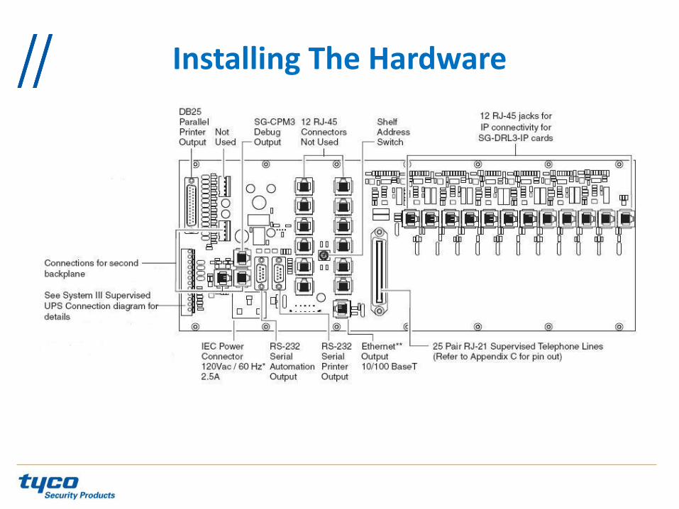
SG-CPM3 This contains the CPU that controls all communication to and from up to 24 line cards, 3 printers, and 2 automation ports

Installing The Hardware
SG-PSU3 The power supply unit that provides power to all modules on the system. *note: A power cord with an IEC connector is required.

Installing The Hardware
SG-DC/DC3 This provides 5 VDC power required for the backplane. A slot exists for a second SG-DC/DC3 voltage converter. In the event of a failure the redundant SG-DC/DC3 can be removed/replaced without powering down the unit.

Installing The Hardware
SG-PSC3 The Power Supply Controller monitors the state of the power and the fan for each SG-MLRF3. It also provides the power for the LCD display on the SG-MLRF3

Installing The Hardware
SG-DRL3 Each SG-DRL3 Line card monitors one telephone line. It stores up to 64 different profiles for data management including 8 different handshaking protocols. Each line card has 512-event buffer , for short term retention of the signals

Installing The Hardware
SG-DRL3E Each SG-DRL3E Line card monitors one telephone line. It stores up to 64 different profiles for data management including 8 different handshaking protocols. Each line card has 512-event buffer , for short term retention of the signals .

Installing The Hardware
SG-DRL3-2L Each SG-DRL3-2L Line card monitors two telephone lines. It stores up to 64 different profiles for data management including 8 different handshaking protocols. Each line card has 512-event buffer , for short term retention of the signals
Note: The green and blue PCB has 100% identical functionality. The blue PCB is a newer hardware revision.

Installing The Hardware
SG-DRL3-IP Each SG-DRL3-IP Line card will monitor up to 1536 DSC IP Communicators. 512 of those IP Communicators can be supervised.

Installing The Hardware
Installing The Hardware

Installing The Hardware
Redundancy Installation

1
2
3
4 5 6 7
8
9
10
1 – Line Monitoring (Phone Line or Network) 2 – Status LED ( or 2nd Line monitoring if DRL3-2L) 3 – Watchdog 4 – AC LED 5 – CPM Status LED 6 – CPM Watchdog 7 – Acknowledge Button 8 – SCROLL Down button 9 – Enter Button 10 – SCROLL Up Button
Installing The Hardware

Operation with Default Programming -Answers incoming calls on the first ring -Send the following handshake order:
1. 2300hz 2. 1400hz 3. Dual tone 4. SIA FSK 5. ITI Modem IIE/IIIa2 6. Modem II
-Receives all communication formats except for 3/2, 3/1 checksum, SKFSK, 4/2 Extended, and 4/2 checksum (enable option 95) -Signals are sent to printer or computer through the serial port COM1 or the Ethernet port (10/100Base T) - If a computer is not connected, need to acknowledge the signals by pressing [ACK] button to silent the buzzer

Virtual Connectivity
-One static IP address per Receiver with associated ports -Each port is used for specific tasks -Configuration management done from the console software is located on port 1024 -The SG Console Software is provided for Microsoft Operating system ( NOT MAC compatible ) -Graphical style menu for configuration management -Additional features are available with the Console software: (Virtual receiver setup storage and configuration wizards)

Automation Input / Output (port 1025)
-Automation communication is provided via port 1025 on the Ethernet connection -Primary port is a Sur-Gard standard output and provides Sur-Gard standard automaton.

Compatibility
Automation software: -MAS -DICE -SIMS II -GENESYS -S.I.S -IBS -MicroKey
Note: the SG Automation protocol is an open document and is available upon request. There are additional automation companies who have fully implemented the protocol.
Automation Protocols
SG-System III receiver send a variety of protocols to report signals to the central station computer via TCP/IP and/or RS-232 port. Complete list of protocols can be provided upon request

Data Byte Protocol
SG-System III uses default configuration to transmit and receive signals on the RS-232 port. Default settings: • 9600 Baud Rate • 1 - start bit • 8 - data bits • 0 - parity • 1 - stop bit structure These parameters are programmable as required.

Acknowledgement of the signal
- The SG-System III requires an acknowledgement signal [ACK] (Hex 06) from automation computer within 4s for each message sent. - Failure to receive [ACK] will result in 3 transmissions of the signal before indicating a communication failure
- During communication fail the receiver will cease transmitting except the heartbeat
- Same thing happens if the receiver receives a [NAK] (Hex 15)
- In case of communication fail with automation computer, the SG-System III can store up to 256 events per line card (line card internal memory)
- Communication is resumed when the first acknowledgement is received on the heartbeat; all buffered information is then transmitted
COM Responses
When the CPM3 sends an event to the computer, it checks for 3 responses: ACK, NAK, or Unknown/No Response - ACK: means the computer got the event successfully
- NAK: means the computer got the message but didn’t understand it . The line card will attempt to send the message 25 time. If after 25 times, it continually gets a NAK, the DLR3 will generate an internal communication error. After 20 NAK, the CPM3 will send an internal communication error event to the printer. Any other response from the computer automation, including no response will cause the CPM3 to attempt to send message again, up to 4 times. - If after 4 attempts the CPM3 get no response or an unknown response, it will assume nothing is connected, generate an alarm and fall to the next active automation port or manual mode.

Automation Absent
-If there is no computer connected, the CPM3 will generate a ‘SG-Serial x Fail’ or ‘SG-TCP/IPx Fail’ trouble -If trouble occurs, the CPM3 will continue to attempt to send a heartbeat signal to the computer until it gets a response.
-The Receiver will make 4 attempts, then wait for the next heartbeat period before making another attempt. The typical heartbeat interval is 30 seconds

Automation Absent
- This signal is used to supervise the communication between the receiver and the computer automation. - It is sent every 30 seconds and is programmable form the receiver. Automation should acknowledge this signal with an [ACK] - It fails to get a response from the automation, the CPM will transmit the heart beat again, up to 4 attempts. - The SG-System III, by default , will output the automation signals via TCP/IP, if TCP/IP fails it switch to Serial Automation port. - If Serial output fails, the CPM3 will switch to manual Mode, all signals will displayed on the LCD and will require a manual acknowledge.

SG-System III SIA Internal Status Output

CPM3 Operation modes
Active Mode: CPM3 communicates properly with Automation Software
Manual Mode: CPM3 doesn't communicate with Automation Software

CPM3 Operation modes
If both CPM3s are present, one will be in Active Mode or Manual Mode and the other one will be on Standby Mode
When a trouble is present in the SG-System III the message ’SYSTEM TROUBLE ‘ will displayed at the bottom of the screen To view the event push the SCROLL UP AND SCROLL DN buttons simultaneously

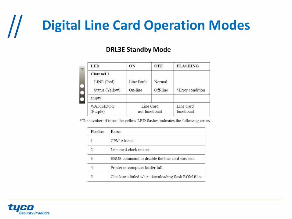
DRL3 Standby Mode
Digital Line Card Operation Modes
DRL3E Standby Mode
Digital Line Card Operation Modes
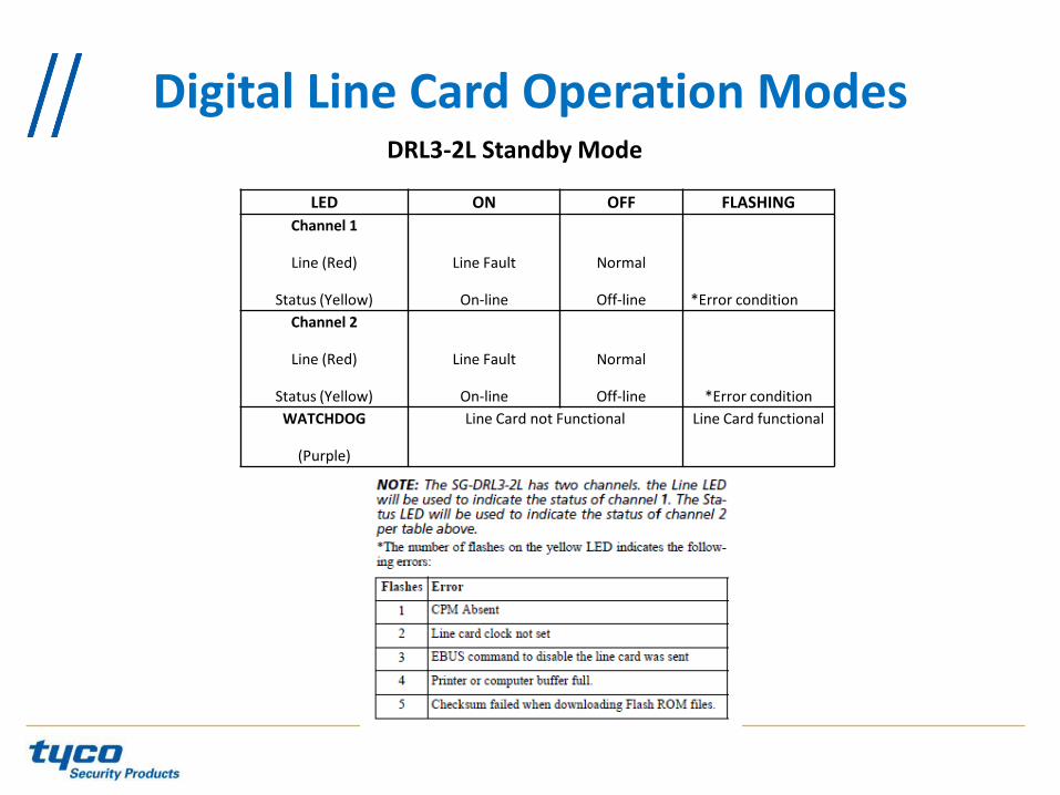
Digital Line Card Operation Modes DRL3-2L Standby Mode
LED ON OFF FLASHING
Channel 1
Line (Red)
Status (Yellow)
Line Fault
On-line
Normal
Off-line
*Error condition
Channel 2
Line (Red)
Status (Yellow)
Line Fault
On-line
Normal
Off-line
*Error condition
WATCHDOG
(Purple)
Line Card not Functional Line Card functional

Digital Line Card Operation Modes
Line Fault The SG-DRL3/SG-DRL3E/SG-DRL3-2L verifies the telephone line voltage. The 'Line Fault' LED (Red) will come ON when the voltage drops below 12VDC. When the line condition returns to normal, the 'Line Fault' LED will be shut OFF. NOTE: Additional line fault operation if Backup Line option is enabled. See Backup Line option (Option 0E) for explanation.

Digital Line Card Operation Modes
SG-CPM3 Error If the line card cannot detect the SG-CPM3 polling, the line card will start buffering incoming calls. Up to 512 alarm messages for the printer and computer will be retained in the line card event buffer. When the event buffer is full, the line card will stop answering calls and the status LED will begin flashing. When the SG-CPM3 Error condition is corrected, the alarm messages in the event buffer will be transmitted to the SG-CPM3 with the corresponding time/date the alarm has been received.

Digital Line Card Operation Modes
SG-DRL3/SG-DRL3E/SG-DRL3-2L Data Reception During data reception, the yellow STATUS LED will turn on. The line card decodes all information received and stores the information in its Event Buffer. When a valid signal is received, the line card sends a kiss-off signal and transmits the decoded alarm signal to the computer and to the printer through the SG-CPM3. The line card will send each message it receives to the printer for review by the system operator. Two messages may be sent to the printer to indicate reception problems: invalid report and communication fail.

Fault Data Message: INVALID REPORT
Digital Line Card Operation Modes
This output for account code '0000' indicates that data has been received, but is not valid (for example, there are unmatched rounds or incorrect parity).

Fault Data Message: COMMUNICATION FAIL
Digital Line Card Operation Modes

SG-DRL3-IP Operation modes Standby Mode

SG-DRL3-IP Operation modes
CPM3 Error

SG-DRL3-IP Operation modes Fault Data Message
Invalid Report

Ethernet Interface
SG-DRL3-IP Operation modes

Supervised Receiver Database
SG-DRL3-IP Operation modes

Programming The CPM3
The SG-CPM3 is programmed using the front LCD screen using the scroll up, scroll down and enter buttons. When the CPM3 IP address is programmed, the rest of programming can be done from the SG System Console V2.0 and Higher.

Step 1: To Enter Programming press the ENTER Key
Step 2: Press ENTER again to choose User 0 • ENTER PASSWORD: USER: 0 PASS: XXXX
Step 3: Scroll UP and Scroll DOWN to change the Password letters and ENTER
to accept it.
The Default Password is CAFE • ENTER PASSWORD: USER: 0 PASS: CAFE
This will take you to the Main Menu
Step 4: Navigate with the Up and Down arrows and make your selection with
Enter. To go back or cancel an entry press the Up and Down together
Programming The CPM3

1) CPM options
Change the options for the CPM3
2) System Functions
Resets the CPM3 and setting the Date and Time for the CPM3
3) Line Card Programming
Change the options for the line cards
4) Exit Programming
Programming The CPM3

CPM3 options
Please see SG-System III Manual v2.0
Programming The CPM3

•The SG-DRL3, SG-DRL3E, SG-DRL3-2L and SG-DRL3-IP are programmed using the SG System Console over the network. •The SG System console connects to the SG-CPM3’s IP address and all programming is sent to the SG-DRL3, SG-DRL3E, SG-DRL3-2L and SG-DRL3-IP via the serial backplane.
Line card Programming
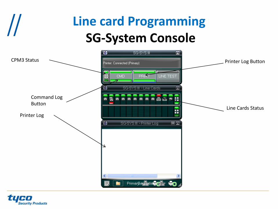
Line card Programming SG-System Console
Command Log Button
Printer Log
Line Cards Status
Printer Log Button CPM3 Status

Line card Programming SG-DRL3/SG-DRL3E/SG-DRL3-2L Programming
1- Right click anywhere on the console
2 - Click on Device Settings

Line card Programming SG-DRL3/SG-DRL3E/SG-DRL3-2L Programming
3- Select the specific line card
4- Select the option #

Line card Programming SG-DRL3/SG-DRL3E/SG-DRL3-2L Programming
1- Select Profile Tab for profile programming
2- Select Profile #

Line card Programming SG-DRL3/SG-DRL3E/SG-DRL3-2L Options
Profiles Introduction The DRL3/DRL3E/DRL3-2L 'virtual receiver' will load unique 'profiles' in order to effectively communicate with control panels. A profile is a set of pre-programmed line card options unique for a particular DNIS number. The 'DNIS' will point to a particular profile, which will then be loaded into the line card before the first handshake is sent. It is essential that the correct option be programmed for a profile in order to correctly communicate with the control panel. Each 'virtual receiver' can have a maximum of 64 profiles. To change the options for a particular profile, the SG-Systems Console software is provided. This software will allow the user/operator to edit the profiles.

Line card Programming SG-DRL3/SG-DRL3E/SG-DRL3-2L Options
Call Processing Flowchart

Line card Programming SG-DRL3/SG-DRL3E/SG-DRL3-2L Options
-Each Profile: Static Options and Dynamic Options -Static Options: the same for all profiles -Dynamic Option: Can be programmed specifically per hunt group, panel type, etc.

Line card Programming SG-DRL3/SG-DRL3E/SG-DRL3-2L Options
Please see SG-System III manual v2.0 for SG-DRL3 and SG-DRL3-2L Options description

ANI and DNIS A PRI-ISDN Provides two features…
• DNIS (Dialled Number Identification Service) – Where the panel is calling too
• DNIS is a 4 or 5 digits identifier of the dialled telephone number
• The SG-System III is able to recognise the DNIS (long distance) or DID (local) number
• A different set of options is loaded depending on which DNIS was received
• ANI (Automatic Number Identification) – Where the panel is calling from (similar to Caller-ID)
• The ANI works together with the Automatic Handshake Selection to provide the right handshake first

ANI and DNIS A PRI-ISDN Provides two features…
665-4494
ANI: 416-665-4494 800-418-7618
DNIS: 7618
DNIS. Where the panel is calling to
ANI. Where the panel is calling from

Programming The SG-System III DNIS Programming
1- Select DNIS Tab
2- Click on New

Programming The SG-System III DNIS Programming
4- Put the desired DNIS #
5- Put the desired profile
3- Select DNIS only or CID/DNIS
6- Click ok

Programming The SG-System III DNIS Programming
7- Click Set

Programming The SG-System III DNIS Programming
1- Select the LineCard #
2- Select the Profile #
3- Program the value field for the specific option#
4- Set the Options

Conventional Handshakes
Handshakes, which one?
HS #1 ? HS #2 ? HS #3 ? HS #4 ? HS #5 ? HS #6 ?
Even if SIA or Contact ID is used, it could take 15 – 20 seconds before the correct handshake is provided. Old Handshakes must come first!
?
Different Formats need Different Handshakes

Conventional Handshakes Which Handshake?
HS #1 = 1 second 2300 Hz
Wait = 4 second
HS #2 = 1 second 1400 Hz
Wait = 4 second
HS #3 = 1 second 2300-1400 Hz
Wait = 4 second
HS #4 = 1 second SIA – “YES”
It will take 16 seconds to the receiver before to send the right Handshake.
Radionics, ITI or Handshake #5-#6 will take longer
?

A Panel is Sending a Signal
665-4494
ANI: 416-665-4494
First Time the Panel Calls to the SG-System III
ANI. Where the panel is calling from
Handshake order in the Profile
• 2300Hz
• 1400 Hz
• Dual-Tone
• SIA
• ITI
AHS – Automatic Handshake Selection
665-4494
ANI: 416-665-4494
800-418-7618
DNIS: 7618
DNIS# Profile
ANI Handshake
416-665-4494 SIA
416-665-4595 99
7618 3
5678 2
How SG-System III takes a call
1. Call comes in 2. ANI received: 416-665-4494 3. DNIS received: 7618 4. Check DNIS table 5. Switch to profile 3 6. Check AHS table 7. Send handshake SIA

The AHS (Automatic Handshake Table) is stored on the SG-CPM3 in volatile memory. New and modified AHS entries that are generated by incoming calls to line cards will be added to the backup CPM3. This operation will happen every 5 minutes. At this time, all entries that are new/modified will be synchronized with the other CPM3. If the two CPM3’s are not able to communicate to each other then the synchronization of the new entries will fail. Note: With the CPM3 V2., the size of the AHS is now 250 000 entries, the customer can purchase a license key to extend the size to 500 000 entries (see CPM3 option 037 and 038). The AHS file from the old console software can be loaded from the SG-Console V2.0 to the new CPM3 V.2, but it will be saved with a new format.
Maintaining The AHS Table

When the SG-Systems Console sets the AHS table to the CPM3 it will be written to flash once the set is complete. The SG-SG-System III will log "AHS Database Full" once the AHS table has reached capacity. The SG-SG-System III will continue to log "AHS Database Full" every day, at midnight, until space in the AHS table is made by deleting entries. The SG Systems Console can be set to make automatic backups of the AHS table. For instructions on how to activate this feature, please see the SG systems Console manual.
Maintaining The AHS Table

Maintaining The AHS Table
Click on Primary CPM3 then select AHS Tab.

Maintaining The AHS Table
Click on Get button
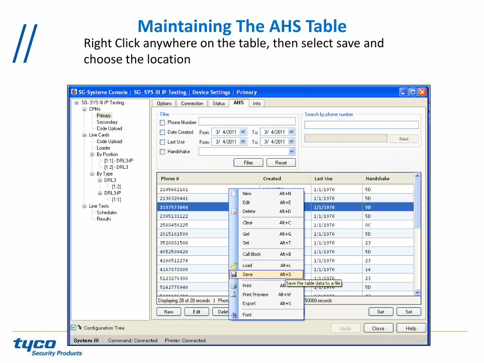
Maintaining The AHS Table Right Click anywhere on the table, then select save and choose the location

Maintaining The AHS Table
Click on CPM3 Secondary
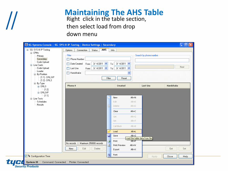
Maintaining The AHS Table Right click in the table section, then select load from drop down menu

Maintaining The AHS Table
Select the file, click open then click on Set button

Line card Programming SG-DRL3-IP Programming
Select IP line card
Select option, put the desired value , then set option

Line card Programming SG-DRL3-IP TLink Table
Select IP line card
Select Account Table 1 Tab Then click on Get

Click on Close
Line card Programming SG-DRL3-IP TLink Table

To manually add account, click on New
Line card Programming SG-DRL3-IP TLink Table

Enter the account # and the encryption key
Line card Programming SG-DRL3-IP TLink Table

Click on Yes
Line card Programming SG-DRL3-IP TLink Table

Click on Close
Line card Programming SG-DRL3-IP TLink Table

Click on Set
Line card Programming SG-DRL3-IP TLink Table

Click on Yes
Line card Programming SG-DRL3-IP TLink Table

Click on Close
Line card Programming SG-DRL3-IP TLink Table

Line card Programming SG-DRL3-IP Options
Please see SG-System III Manual v2.0

There are six different items that have to be upgraded on the SG-System III 1. The SG System Console 2. The SG-CPM3 3. The SG-DRL3 4. The SG-DRL3E 5. The SG-DRL3-2L 6. The SG-DRL3-IP
Upgrading The Receiver

Upgrading The Receiver SG System Console
On the new SG- Console V2.0, there is two components: Server and Client The server:
has to be installed at 1 location, it run as a “True” Server; if customer reboots the computer , the server will start and reconnect automatically.(Make sure the Automatic Reconnect is checked when you create a new configuration)
The Client: Can be installed at multiple locations. A new configuration will be created from a client then all the information will be sent to the server and stored on it. On the client, the admin session, give you access to everything but a user session can be created for limited access only.

Upgrading The Receiver SG System Console
Requirements and Recommendations for the SG System Console V2.0 and Higher
Computers Requirements (Client and Server): - 1 gigahertz (GHz) or faster 32-bit (x86) or 64-bit (x64) processor - 1 gigabyte (GB) RAM (32-bit) or 2 GB RAM (64-bit) - 16 GB available hard disk space (32-bit) or 20 GB (64-bit) - DirectX 9 graphics device with WDDM 1.0 or higher driver
Recommendations: - Run up to 35 different configurations on the same computer - Connect up to 5 Clients to the same receiver (1 Admin + 4 Users)

Upgrading The Receiver SG System Console
The server
Launch the Server Installation

Upgrading The Receiver SG System Console
The server
Accept the terms

Upgrading The Receiver SG System Console
The server
Choose the location

Upgrading The Receiver SG System Console
The server
Confirm the installation, Click Next
Upgrading The Receiver SG System Console
The server
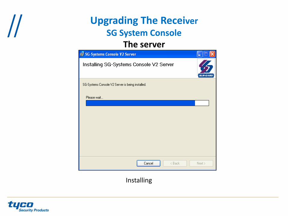
Installing

Upgrading The Receiver SG System Console
The server
Setting of firewall exception, by default the Server port is 9000
Upgrading The Receiver SG System Console
The server
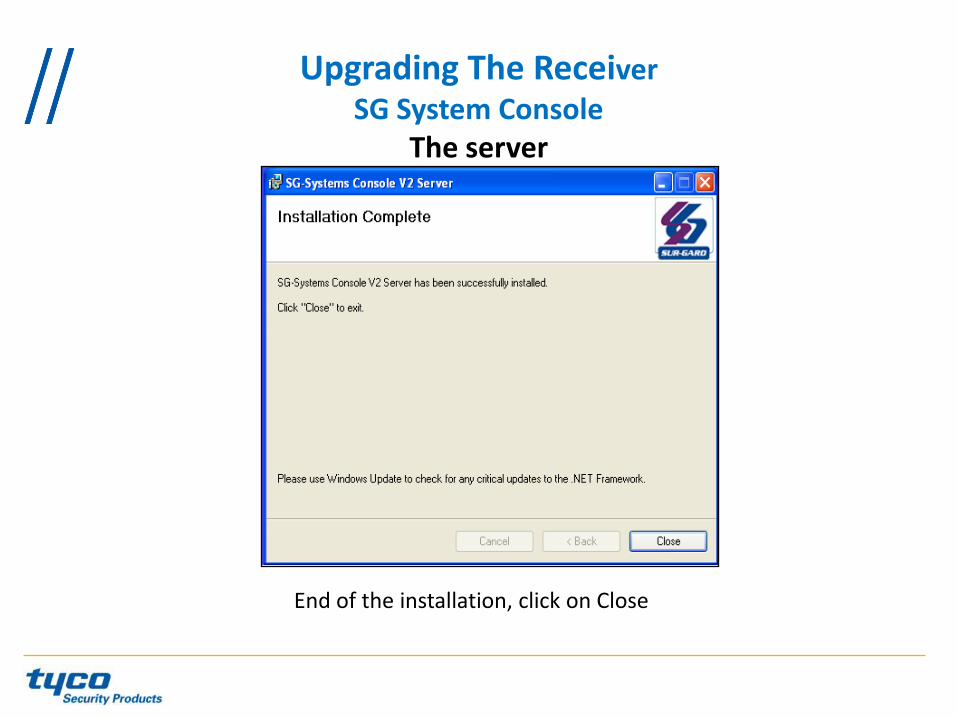
End of the installation, click on Close

Upgrading The Receiver SG System Console
The server
An icon will be added to the desktop
Upgrading The Receiver SG System Console
The server
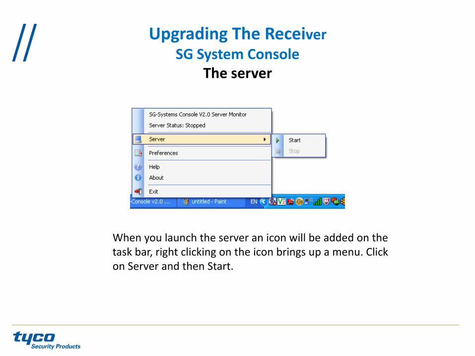
When you launch the server an icon will be added on the task bar, right clicking on the icon brings up a menu. Click on Server and then Start.

Upgrading The Receiver SG System Console
The server
Starting the server displays the above.

Upgrading The Receiver SG System Console
The Client
Launch the client installation
Upgrading The Receiver SG System Console
The Client
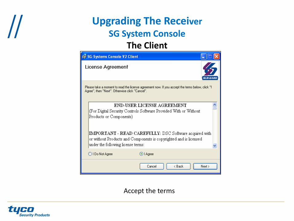
Accept the terms

Upgrading The Receiver SG System Console
The Client
Choose the Location
Upgrading The Receiver SG System Console
The Client
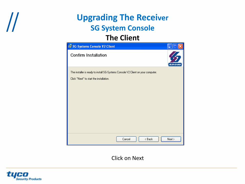
Click on Next

Upgrading The Receiver SG System Console
The Client
Installing

Upgrading The Receiver SG System Console
The Client
End of the Installation click on Close

Upgrading The Receiver SG System Console
The Client
An icon will be added to the desktop
Upgrading The Receiver SG System Console
The Client
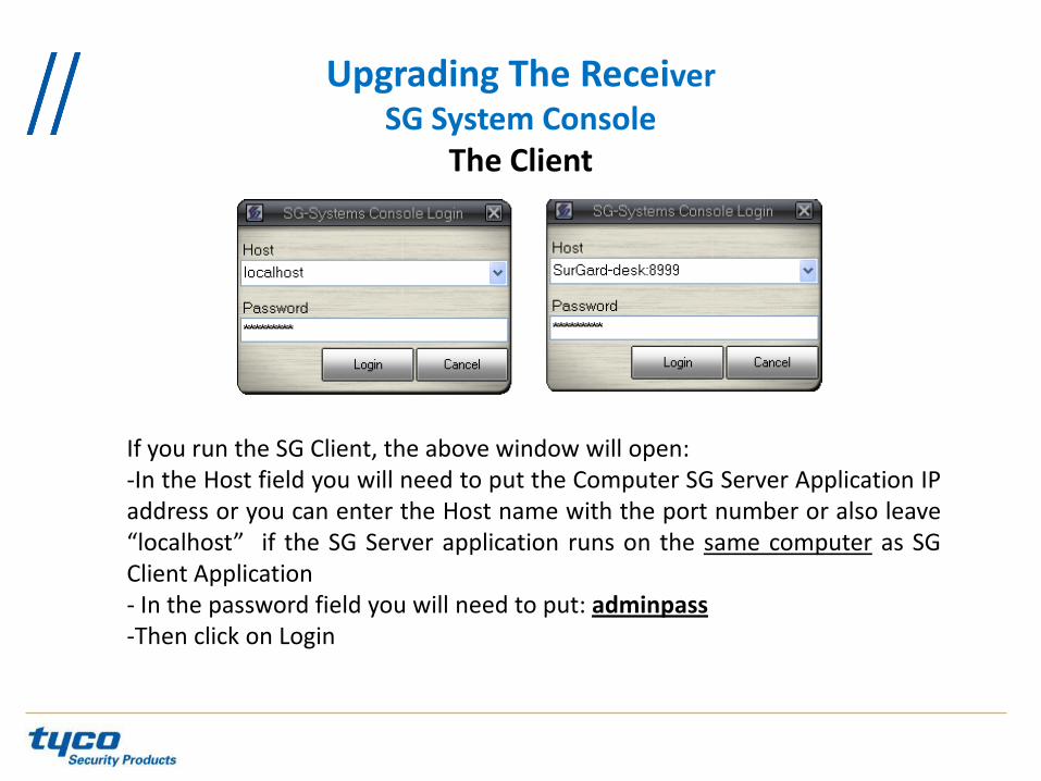
If you run the SG Client, the above window will open: -In the Host field you will need to put the Computer SG Server Application IP address or you can enter the Host name with the port number or also leave “localhost” if the SG Server application runs on the same computer as SG Client Application - In the password field you will need to put: adminpass -Then click on Login

Upgrading The Receiver SG System Console
The Client

Upgrading The Receiver SG System Console
The Client

Upgrading The Receiver SG System Console
The Client
Choose the type of receiver, field the name of the Receiver and make sure you have a check mark on « Automatically connect to receiver on startup »

Upgrading The Receiver SG System Console
The Client
Put the Primary CPM3 IP address

Upgrading The Receiver SG System Console
The Client
Ensure the Enabled option is checked. Then enter the Secondary CPM3 IP address

Upgrading The Receiver SG System Console
The Client
Do a test configuration

Upgrading The Receiver SG System Console
The Client
The Client is disconnected
Upgrading The Receiver SG System Console
The Client
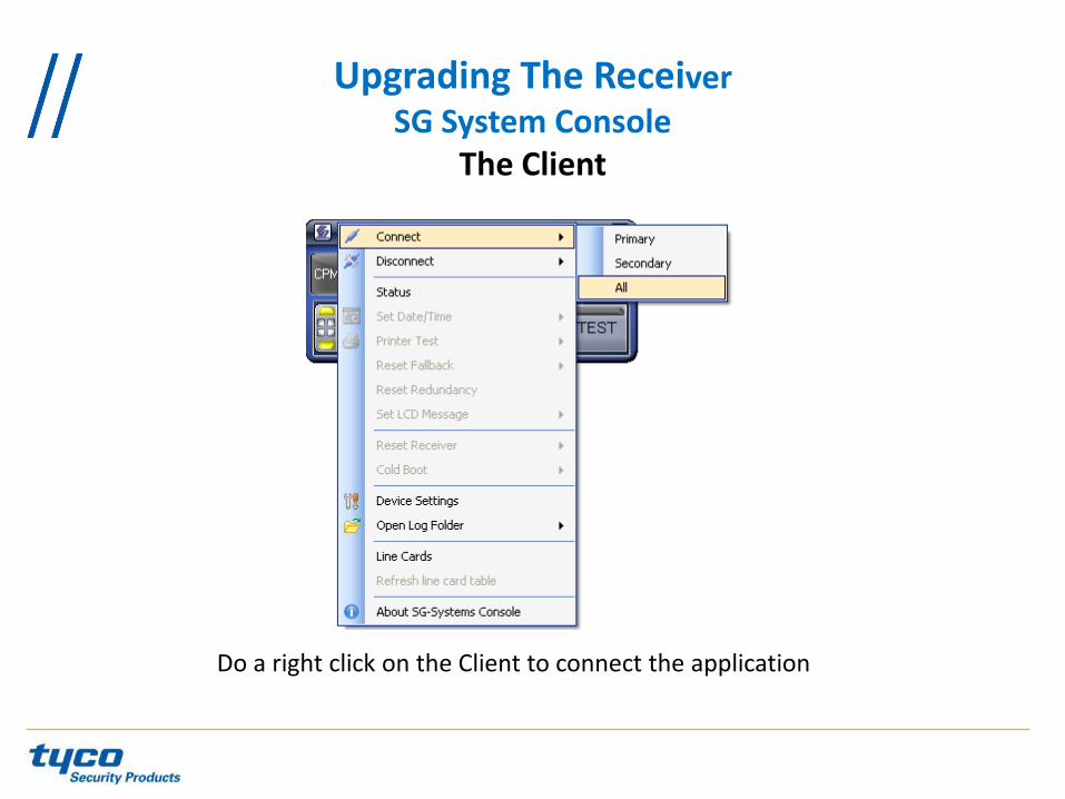
Do a right click on the Client to connect the application

Upgrading The Receiver SG System Console
The Client
The Client is now connected
Upgrading The Receiver SG System Console
The Client
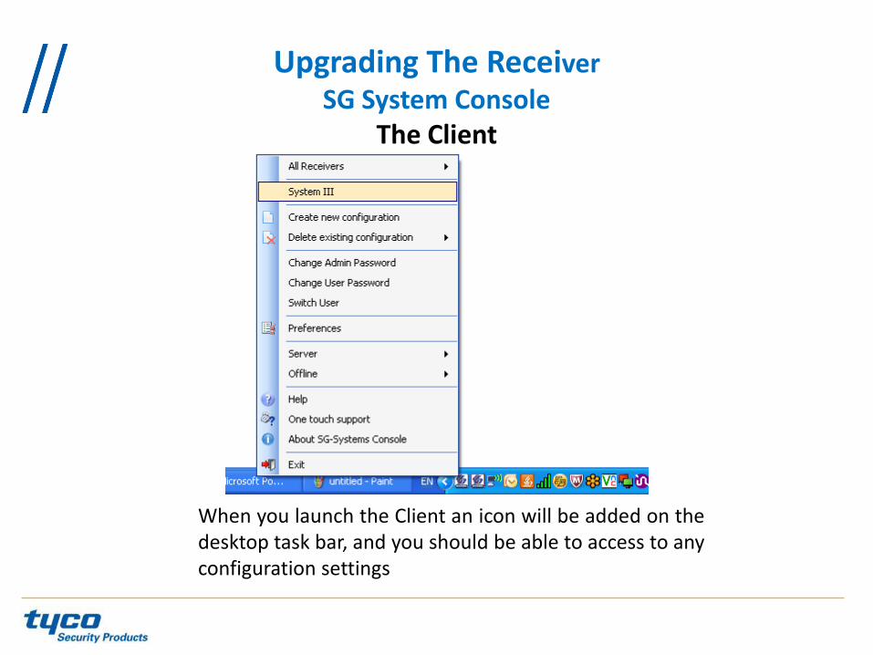
When you launch the Client an icon will be added on the desktop task bar, and you should be able to access to any configuration settings

Note : If you upgrade from a software version below 2.0 to a software version 2.0, the followings are the requirements: •Hardware Requirements: ROHS CPM3 •Software: Bridger File V2.0 and Firmware file v2.0 (encrypted) •CPM3 Upgrade Procedure:
- Upgrade it’s done from the SG-Console V2.0 - Load the Bridger file first, once it’s done load the V2.00 firmware
Upgrading The Receiver SG-CPM3

Upgrading The Receiver SG-CPM3
Select Code Upload in the CPM menu, select the CPM destination (Primary or Secondary), then click code file icon

Upgrading The Receiver SG-CPM3
Click on New
Upgrading The Receiver SG-CPM3
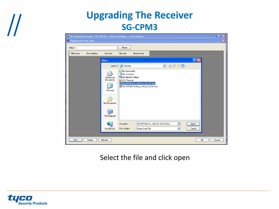
Select the file and click open

Upgrading The Receiver SG-CPM3
Put a description of the file then click on Ok

Upgrading The Receiver SG-CPM3
The file is sent to the server
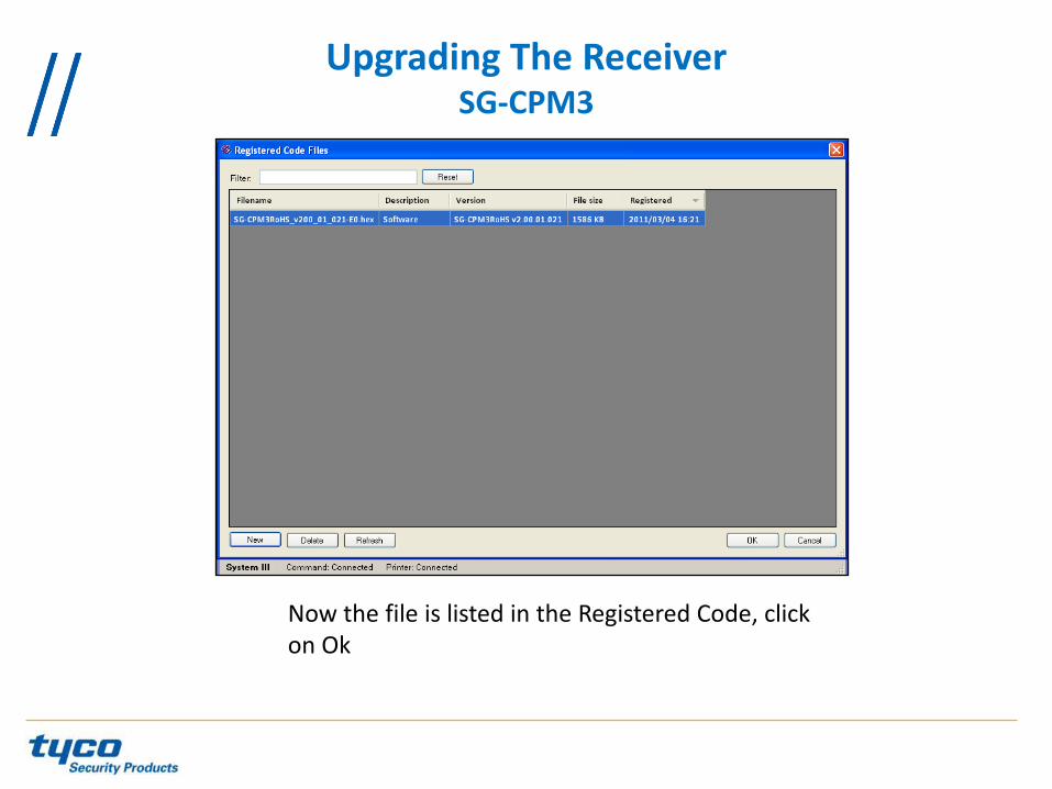
Now the file is listed in the Registered Code, click on Ok
Upgrading The Receiver SG-CPM3

Click on upload to send the software to the CPM3
Upgrading The Receiver SG-CPM3

Upgrading The Receiver Line card Upgrade
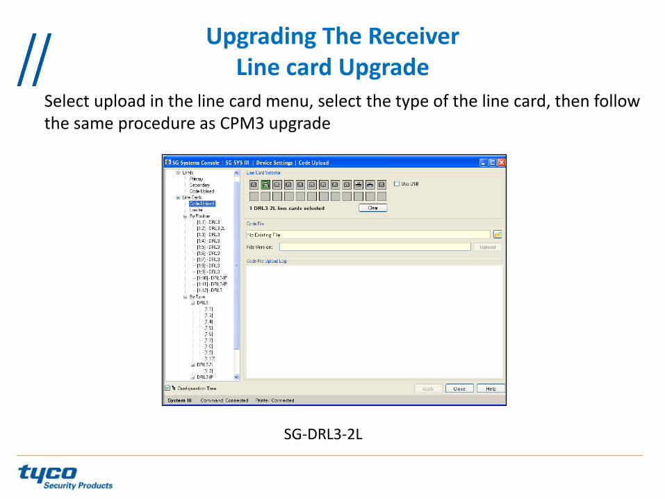
Select upload in the line card menu, select the type of the line card, then follow the same procedure as CPM3 upgrade
SG-DRL3/SG-DRL3E
Upgrading The Receiver Line card Upgrade
Select upload in the line card menu, select the type of the line card, then follow the same procedure as CPM3 upgrade
SG-DRL3-2L

Upgrading The Receiver Line card Upgrade
Select upload in the line card menu, select the type of the line card, then follow the same procedure as CPM3 upgrade
SG-DRL3-IP

Troubleshooting
There are many formats that the SG-System III can receive. Some of those formats will conflict with one another. It is very important when creating your profiles that you know what type of formats you will be receiving. The first thing that should be done is getting a copy of any receiver you will be replacing programming. The most important item is the handshake order.
HS #1 = 1 second 2300 Hz HS #2 = 1 second 1400 Hz HS #3 = 1 second 2300-1400 Hz HS #4 = 1 second SIA
Troubleshooting
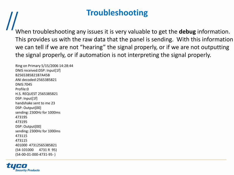
When troubleshooting any issues it is very valuable to get the debug information. This provides us with the raw data that the panel is sending. With this information we can tell if we are not “hearing” the signal properly, or if we are not outputting the signal properly, or if automation is not interpreting the signal properly. Ring on Primary 5/15/2006 14:28:44 DNIS received:DSP: Input[1f] B2565385821B7A45B ANI decoded:2565385821 DNIS:7045 Profile:0 H.S. REQUEST 2565385821 DSP: Input[1f] handshake sent to me 23 DSP: Output[00] sending: 2300Hz for 1000ms 473195 473195 DSP: Output[00] sending: 2300Hz for 1000ms 473115 473115 401000 47312565385821 (54-101000 4731 R 95) (54-00-01-000-4731-95- )

The following options can be used for basic programming settings, for advanced programming, please to refer to the manual.
Basic Programming Setting

Basic Programming Setting Enable Caller ID option (Printer and Automation)
SG-DRL3 options: - Option 12: 01 - Option 13: 01 - Option 14: 01 - Option 20: 01 -Option 27: 0A
SG-DRL3E/SG-DRL3-2L options: - Option 112/212: 01 -Option 113/213: 01 -Option 114/214: 01 -Option 044: 01 (Line card System Option) -Option 127/227: 0A

Basic Programming Setting Enable ANI and DNIS options
Using 4 digits DNIS SG-DRL3 options: - Option 02: 02 - Option 12: 45 - Option 13: 04 - Option 14: 04 - Option 20: 04 - Option 27: 04 SG-DRL3E/SG-DRL3-2L options: - Option 041: 02 (Line card System Option) - Option 112/212: 45 -Option 113/213: 04 -Option 114/214: 04 -Option 044: 04 (Line card System Option) -Option 127/227: 04 CPM3 Options: - Option 10: 4 - Option 11: 4

Using 5 digits DNIS SG-DRL3 options: - Option 02: 0A - Option 12: 46 - Option 13: 04 - Option 14: 04 - Option 20: 04 -Option 27: 05
SG-DRL3E/SG-DRL3-2L options: - Option 041: 0A (Line card System Option) - Option 112/212: 46 - Option 113/213: 04 - Option 114/214: 04 - Option 044: 04 (Line card System Option) - Option 127/227: 05 CPM3 options - Option 10: 5 - Option 11: 5
Basic Programming Setting Enable ANI and DNIS options
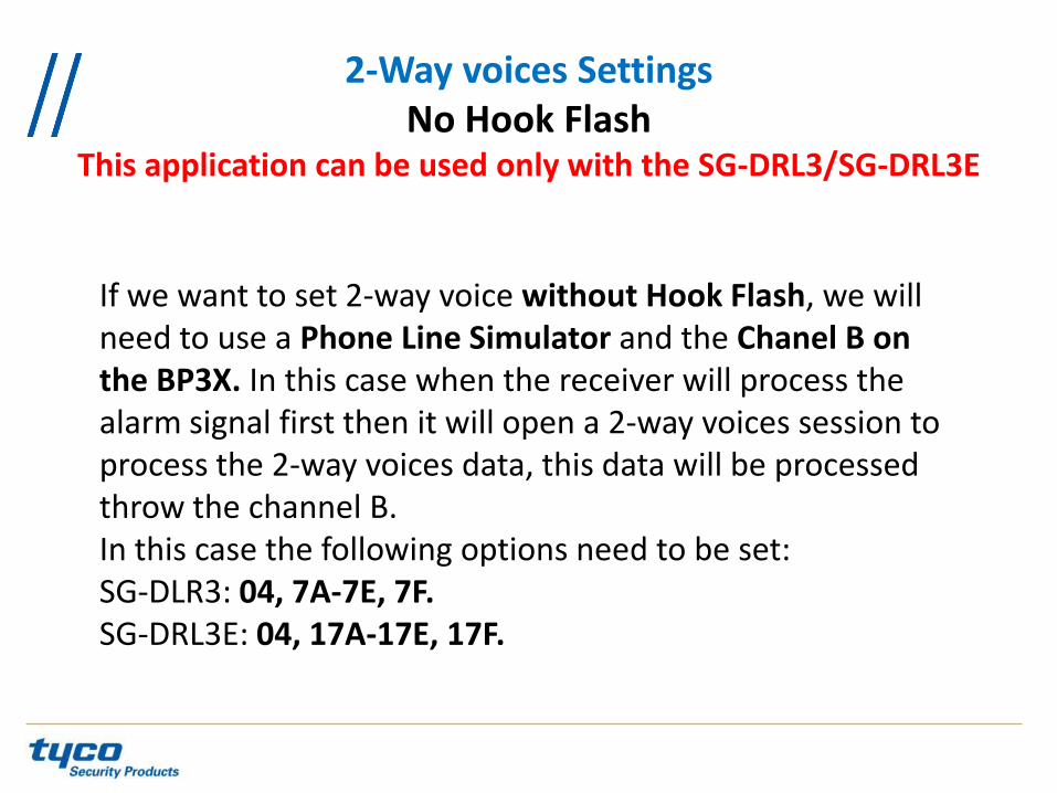
If we want to set 2-way voice without Hook Flash, we will need to use a Phone Line Simulator and the Chanel B on the BP3X. In this case when the receiver will process the alarm signal first then it will open a 2-way voices session to process the 2-way voices data, this data will be processed throw the channel B. In this case the following options need to be set: SG-DLR3: 04, 7A-7E, 7F. SG-DRL3E: 04, 17A-17E, 17F.
2-Way voices Settings No Hook Flash
This application can be used only with the SG-DRL3/SG-DRL3E

If we want to set up 2-way voice With Hook Flash, first we have to make sure the phone system can support the Hook Flash. In this case when the receiver will process the alarm signal first then it will open a 2-way voices session by dialing an extension or a number and then transferring the call to this extension. In this case the following options need to be set on the SG-DRL3:11, 2A, 7A-7E, 7F, A8-AF. SG-DRL3E/SG-DRL3-2L: 111/211, 12A/22A, 17A-17E/217A-27E, 17F/27F, 1A8-1AF/2A8-2AF
2-Way voices Settings With Hook Flash

QUESTIONS & ANSWERS