Embed Size (px)
Citation preview
8/12/2019 Surcharge Calculator
http://slidepdf.com/reader/full/surcharge-calculator 1/7
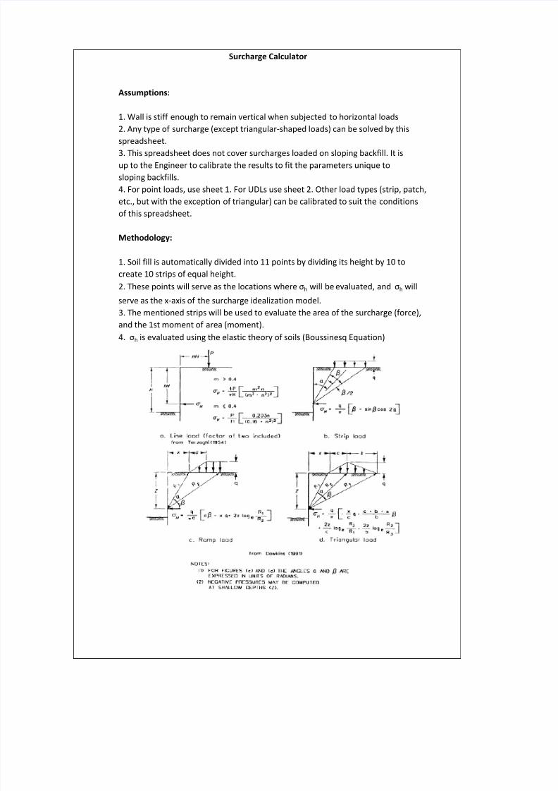
Assumptions:
1. Wall is stiff enough to remain vertical when subjected to horizontal loads2. Any type of surcharge (except triangular-shaped loads) can be solved by this
spreadsheet.3. This spreadsheet does not cover surcharges loaded on sloping backfill. It isup to the Engineer to calibrate the results to fit the parameters unique tosloping backfills.4. For point loads, use sheet 1. For UDLs use sheet 2. Other load types (strip, patch,etc., but with the exception of triangular) can be calibrated to suit the conditionsof this spreadsheet.
Methodology:
1. Soil fill is automatically divided into 11 points by dividing its height by 10 to
create 10 strips of equal height.2. These points will serve as the locations where σh will be evaluated, and σ h will
serve as the x-axis of the surcharge idealization model.3. The mentioned strips will be used to evaluate the area of the surcharge (force),and the 1st moment of area (moment).4. σ h is evaluated using the elastic theory of soils (Boussinesq Equation)
Surcharge Calculator
8/12/2019 Surcharge Calculator
http://slidepdf.com/reader/full/surcharge-calculator 2/7
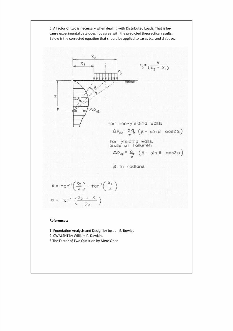
5. A factor of two is necessary when dealing with Distributed Loads. That is be-cause experimental data does not agree with the predicted theorectical results.Below is the corrected equation that should be applied to cases b,c, and d above.
References:
1. Foundation Analysis and Design by Joseph E. Bowles2. CWALSHT by William P. Dawkins3.The Factor of Two Question by Mete Oner
8/12/2019 Surcharge Calculator
http://slidepdf.com/reader/full/surcharge-calculator 3/7
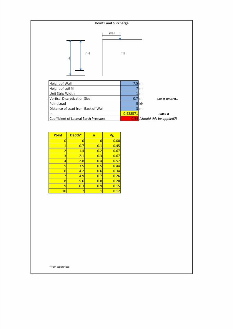
mH
nH fill
H
7.5 m7 m1 m
0.7 m :.set at 10% of H fill
5 kN3 m
0.428571 :.case a0.34 (should this be applied?)
Point Depth* n σ h
0 0 0 0.001 0.7 0.1 0.452 1.4 0.2 0.673 2.1 0.3 0.674 2.8 0.4 0.575 3.5 0.5 0.446 4.2 0.6 0.347 4.9 0.7 0.268 5.6 0.8 0.209 6.3 0.9 0.15
10 7 1 0.12
*from top surface
Point LoadDistance of Load from Back of Wall
mCoefficient of Lateral Earth Pressure
Point Load Surcharge
Height of WallHeight of soil fillUnit Strip WidthVertical Discretization Size
8/12/2019 Surcharge Calculator
http://slidepdf.com/reader/full/surcharge-calculator 4/7
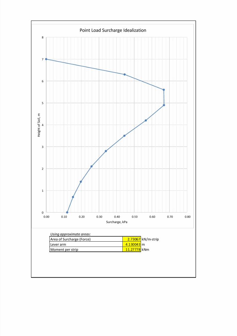
Using approximate areas: 2.73067 kN/m-strip4.130043 m11.27778 kNm
Area of Surcharge (Force)Lever armMoment per strip
0
1
2
3
4
5
6
7
8
0.00 0.10 0.20 0.30 0.40 0.50 0.60 0.70 0.80
H e i g
h t o
f S o i l ,
m
Surcharge, kPa
Point Load Surcharge Idealization
8/12/2019 Surcharge Calculator
http://slidepdf.com/reader/full/surcharge-calculator 5/7
α' β β'α β/2
H σh
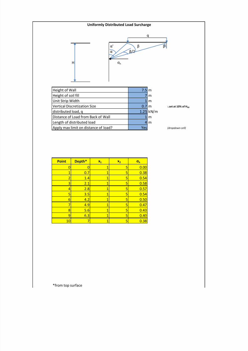
7.5 m7 m1 m
0.7 m :.set at 10% of H fill
1.25 kN/m1 m
4 mYes (dropdown cell)
Point Depth* x1 x2 σ h
0 0 1 5 0.001 0.7 1 5 0.382 1.4 1 5 0.54
3 2.1 1 5 0.584 2.8 1 5 0.575 3.5 1 5 0.546 4.2 1 5 0.507 4.9 1 5 0.478 5.6 1 5 0.439 6.3 1 5 0.40
10 7 1 5 0.38
*from top surface
Uniformly Distributed Load Surcharge
Apply max limit on distance of load?Length of distributed load
q
Height of WallHeight of soil fillUnit Strip WidthVertical Discretization Sizedistributed load, qDistance of Load from Back of Wall
8/12/2019 Surcharge Calculator
http://slidepdf.com/reader/full/surcharge-calculator 6/7
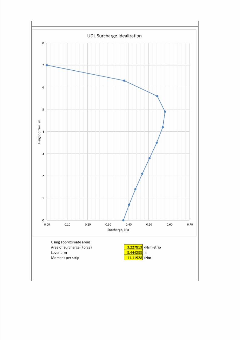
Using approximate areas:Area of Surcharge (Force) 3.227813 kN/m-stripLever arm 3.444833 mMoment per strip 11.11928 kNm
0
1
2
3
4
5
6
7
8
0.00 0.10 0.20 0.30 0.40 0.50 0.60 0.70
H e i g
h t o
f S o i l , m
Surcharge, kPa
UDL Surcharge Idealization

8/12/2019 Surcharge Calculator
http://slidepdf.com/reader/full/surcharge-calculator 7/7