Embed Size (px)
Citation preview
THESIS FOR THE DEGREE OF LICENTIATE ENGINEERING
Surface Characterization of Soft Magnetic Composite
Powder and Compacts
Christos Oikonomou
Department of Materials and Manufacturing Technology
CHALMERS UNIVERSITY OF TECHNOLOGY
Gothenburg, Sweden 2014
II
Surface Characterization of Soft Magnetic Composite Powder and Compacts
CHRISTOS OIKONOMOU
© Christos Oikonomou, 2014
ISSN 1652-8891
No. 95/2014
Department of Materials and Manufacturing Technology
Chalmers University of Technology
SE-412 96 Gothenburg
Sweden
Telephone: ++46(0)31-772 1000
Printed by Chalmers Reproservice
Gothenburg, Sweden 2014

III
“I thank y’all for letting me be here with you.
Whether I know what to say about it or not, it means a lot to me,
and I thank you, okay?”
-SRV

IV
V
Surface Characterization of Soft Magnetic Composite
Powder and Compacts
Christos Oikonomou
Department of Materials and Manufacturing Technology
Chalmers University of Technology
Abstract
Soft Magnetic Composite (SMC) components produced based on traditional Powder Metallurgical
(PM) techniques, are strong candidate materials for electromagnetic applications. Their advantages are
based on profitable and energy efficient production methods, shape complexity realization and
uniquely uniform and isotropic 3D magnetic properties. SMC powder grades consist of individually
encapsulated iron powder particles with an ultra-fine, electrically insulating surface coating.
Component manufacturing procedure involves compaction of the admixed SMC base powder with a
lubricant to a final shape, as well as a subsequent heat-treatment that aims on the relaxation of stresses
induced during the compaction. The concept of SMC is based on taking advantage of the insulating
properties of the surface coating and creating a laminated stack in a powder form. In this manner,
products with comparable or superior magnetic performances can be produced as opposed to the more
traditional laminated steels and ferrites, due to the higher reduction of eddy currents especially at high
frequency applications.
The insulating coating constitutes the paramount feature of the SMC technology. Its morphology,
thickness, cohesion to the powder particles surface and durability during processing, are critical
aspects to the properties of a finished component. Hence, a methodology based on analytical
techniques was developed and implemented on commercially available SMC base powder and
finished components, in order to address these matters for such insulating coatings on a micro-level.
Standard methods previously used for the powder surface characterization have been significantly
modified due to the non-conductive nature of the surface coating. A theoretical model for thickness
determination of the surface layer for powders, based on X-ray photoelectron spectroscopy (XPS)
depth profiling, was further developed and experimentally evaluated. The theoretical results showed
only minor deviations of the order of 3% with the experimental values. The novelty of the latter lies in
its ability to take into account the artifacts imposed to an analysis due to the geometries of the sample
and of the current experimental arrangement.
The surface analysis of the SMC base powder revealed the presence of a uniform, inorganic, iron
phosphate based coating with good overall coverage and coherence to the core. Its chemical depth
profile was evaluated and its thickness was determined by implementing the theoretical model.
Additionally, the thermal stability of the insulating coating of finished SMC components was
investigated under different temperature regimes. The implementation of the previously developed
methodology highlighted the difference of the heat-treatment effect on the interior and exterior regions
of the components in terms of surface chemistry. In this context, increased oxidation was observed in
the area close to the surface of the parts, as opposed to the center, while the analysis also showed that
incomplete de-lubrication is taking place at temperatures below 500°C.
Keywords: X-ray photoelectron spectroscopy (XPS), high resolution scanning electron microscopy
(HR SEM), energy dispersive X-ray spectroscopy (EDX), focused ion beam (FIB),
soft magnetic composites (SMC), powder metallurgy (PM), surface layers, depth
profiling, thickness determination

VI
VII
Preface
This licentiate thesis is based on the work performed at the department of Materials and
Manufacturing Technology at Chalmers University of Technology between January 2011 and
December 2013. The project has been carried out under the supervision of Associate
Professor Eduard Hryha and Professor Lars Nyborg.
This thesis consists of an introductory part followed by the appended technical papers:
Paper I: Evaluation of the thickness and roughness of homogeneous surface layers on
spherical and irregular powder particles
C. Oikonomou, D. Nikas, E. Hryha, L. Nyborg
Early View (Online Version of Record published before inclusion in an issue)
Paper II: Development of methodology for surface analysis of soft magnetic composite
powders
C. Oikonomou, E. Hryha, L. Nyborg
Surface and Interface Analysis
Volume 44, Issue 8, pages 1166–1170, August 2012
Paper III: Effect of Heat Treatment in Air on Surface Composition of Soft Magnetic
Composite Components
C. Oikonomou, R. Oro, E. Hryha, L. Nyborg
Submitted for publication in Materials Science and Engineering: B
The author performed the experimental part of the thesis except the FIB measurements in
Paper I and XRD measurements in Paper III that were carried out by Dr. Yiming Yao and Dr.
Raquel De Oro Calderón respectively. The source code for the computer software that was
developed for the needs of the theoretical model presented in this thesis was written by
Yaroslav Kish. The author wrote the first draft versions of the papers and finalized them in
close collaboration with Professor Lars Nyborg and Associate Professor Eduard Hryha.

VIII
IX
Table of contents
Abstract………………….………..…………………………………………………………..V
Preface…………………………...………………………………………………………….VII
1. Introduction……….……………………………………….……………...……………….1
1.1. Background………………….…………………………………………………………1
1.2. Scope and goal of this study…...………………………….…………………………...2
2. Soft Magnetic materials…………..…………………………..………….………………..3
2.1. Overview……………………………………………….…………...…………………3
2.2. Core loses…...........…………….……………………………………………………..4
2.3. Materials and applications………..…………………………….……………………..4
3. Soft Magnetic Composites………………………………………………………….….…7
3.1. Overview………………………….……………………………………………….…..7
3.2. Insulating coating………..…….…………………………………………….…….…..8
3.3. Processing of SMC materials...………………………………………………………..9
4. Materials and experimental details…………………………………………………….11
4.1. Materials……………………………………………………………………………..11
4.1.1. Pure iron powder……………………………………………………………….11
4.1.2. Somaloy® 500 material…………………………………………………………12
4.2. Analytical techniques………………………………………………………………...12
4.2.1. X-ray Photoelectron Spectroscopy……………………………………………..12
4.2.2. High Resolution Electron Microscopy…………………………………………14
4.2.3. Focused Ion Beam……………………………………………………………...14
4.2.4. X-ray Diffraction…………………………………………………………….…15
5. Results and summary of appended papers…………………………………………….17
5.1. Theoretical model development for layer thickness determination on powder……...17
5.2. Characterization of SMC powder...………………………………………………….21
5.3. Investigation of finished SMC components…….……………………………………23
6. Conclusions……………………………...……………………………………………….29
7. Suggestions for future work…………………………………………………………….31
7.1. Theoretical model development……………………………………………………...31
7.2. SMC analysis………………………………………………………………………...31
8. Acknowledgments……………………………………………………………………….33
9. References……..…………………………………………………………………………35

X
1
1. Introduction
In this section, a brief description of Soft Magnetic Composite materials is given along with
the thesis scope and goals for contributing to this field.
1.1. Background
Energy efficiency strategies have drawn much attention in the last decades, constituting a
major part of the whole sustainable energy development effort. Nowadays, new policies for
energy preservation are being introduced globally along with new legislations that target to
the stabilization and reduction of the total CO2 emissions in energy production, residential and
commercial consumption, transportation and industry [1]. In this context, electromagnetic
applications can prove to be beneficial if one takes into account the possibilities of their
involvement in all of these fields. Power circuits, communication devices, microelectronics,
automotive applications, household appliances and many more categories of contemporary
utilities, all make use of the electromagnetic effect for energy storage and conversion [2].
Related to these phenomena though are energy losses, namely core losses, due to inherent
material properties that reduce the efficiency of the applications by dissipating energy in the
form of heat. Hence, the need for new improved materials for such type of purposes is
constant and basically driven by an outgrowing consumption demand.
Soft magnets comprise the other most important family of ferromagnetic materials, along with
the hard magnets, which are defined by their ease to magnetize and demagnetize even when
subjected to low external magnetic fields. They have been being widely used as core for
inductors and transformers in both DC and AC applications [2, 3]. Typically, steel laminated
structures and ferrites are preferred due to their higher electrical resistivity. This attribute is
essential in reducing the core losses by preventing the circulation of the deleterious induced
eddy currents, especially at higher frequencies. The growth though of fields such as
information technology, high frequency applications and electric motors increase the demand
for more sophisticated technologies, which in turn push towards size reduction and new
complex designs that often test the limits of these more traditional solutions.
Promising alternatives to the latter are iron powdered cores, produced by compaction of
individual electrically insulated powder particles under high pressures into compact solid
forms. The idea behind this concept dates back to the 19th
century, though the advance in
materials science and production techniques have given it a significant boost in the last
decades. These materials, often termed as Soft Magnetic Composites (SMC), are being
manufactured today by conventional powder metallurgical techniques [4, 5]. Their advantages
lie in their isotropic nature and high electrical resistivity, which open up new design
possibilities for weight, energy losses and cost production reductions. Proper material
selection and process treatment are hence important aspects that can further promote the
flexibility of this technology in terms of applications. Therefore, the primary research volume
2
related to the improvement of SMC properties focuses on the development of more exotic and
functional insulating materials, as well as various coating methods [6-8].
Thus, in order to promote this effort, the development of robust analysis methods can be
proven crucial in delivering fundamental knowledge and tools in further understanding the
materials under question.
1.2. Scope and goal of this study
The superior bulk electrical resistivity of SMC products, as compared to their laminated steel
or ferrite counterparts, can be entirely attributed to the insulating material that encapsulates
and separates each individual metal particle. Their electromagnetic performance is much
dependent on the viability and behavior of this coating under different process treatments [9].
It is thus the scope of the present study to investigate the nature of such type of layers, both in
as-received and processed forms. Their morphological, structural and chemical
characterization as well as the assessment and improvement of their treatment are highly
prioritized.
To achieve this, the goal was set initially to develop a methodology based on analytical
techniques that would enable the evaluation of the homogeneity, chemical composition vs
depth and thickness of the insulating coating. To that end, a theoretical model was
additionally developed for surface products thickness determination using surface sensitive
analytical technique and implemented to the material of interest. Finally, heat-treatment was
selected for investigation as the most important process parameter influencing the state of the
insulating coating, and hence the performance of the final SMC product. The effect of the
heat-treatment parameters on the quality of the coating was assessed by means of the
methodology developed.
3
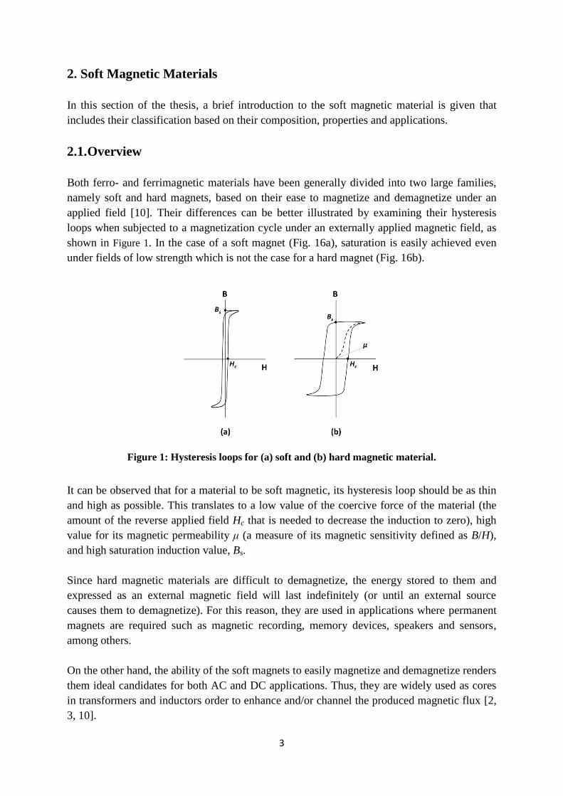
2. Soft Magnetic Materials
In this section of the thesis, a brief introduction to the soft magnetic material is given that
includes their classification based on their composition, properties and applications.
2.1. Overview
Both ferro- and ferrimagnetic materials have been generally divided into two large families,
namely soft and hard magnets, based on their ease to magnetize and demagnetize under an
applied field [10]. Their differences can be better illustrated by examining their hysteresis
loops when subjected to a magnetization cycle under an externally applied magnetic field, as
shown in Figure 1. In the case of a soft magnet (Fig. 16a), saturation is easily achieved even
under fields of low strength which is not the case for a hard magnet (Fig. 16b).
Figure 1: Hysteresis loops for (a) soft and (b) hard magnetic material.
It can be observed that for a material to be soft magnetic, its hysteresis loop should be as thin
and high as possible. This translates to a low value of the coercive force of the material (the
amount of the reverse applied field Hc that is needed to decrease the induction to zero), high
value for its magnetic permeability μ (a measure of its magnetic sensitivity defined as B/H),
and high saturation induction value, Bs.
Since hard magnetic materials are difficult to demagnetize, the energy stored to them and
expressed as an external magnetic field will last indefinitely (or until an external source
causes them to demagnetize). For this reason, they are used in applications where permanent
magnets are required such as magnetic recording, memory devices, speakers and sensors,
among others.
On the other hand, the ability of the soft magnets to easily magnetize and demagnetize renders
them ideal candidates for both AC and DC applications. Thus, they are widely used as cores
in transformers and inductors order to enhance and/or channel the produced magnetic flux [2,
3, 10].
4
2.2. Core losses
The dissipation of energy in a magnetic core during its magnetization and demagnetization
cycle is widely termed as core losses. While these are not of high importance for hard
magnets, they are crucial in the efficiency of soft magnetic applications and can be controlled
with proper material selection [3, 4, 10]. Core losses are generally divided into three
categories, namely hysteresis losses (Ph), eddy current losses (Pe) and residual losses (Pr).
The hysteresis loses originate from the movement of the domain walls back and forth under a
magnetization/demagnetization loop. The presence of impurities, precipitates, imperfections,
grain boundaries and dislocations act as barriers towards this motion and increase those loses.
These can be measured from the internal area of the hysteresis loop and exhibit a linear
relationship with the frequency of the applied field.
The eddy current losses, alternatively named classical eddy current losses, are caused by the
existence of stray electric currents that circulate into the bulk of the material. The subjection
of a magnetic material to a fluctuating magnetic field induces swirling currents in rotating
patterns that eventually dissipate energy in the form of heat. Classical eddy currents are
considered macroscopic and become extremely importance in high frequency applications due
to their squared relationship with the latter.
The residual losses, also called anomalous losses or excess eddy current losses, are dynamic
losses related to the circulation of the eddy currents due to domain wall motion but on the
microscale [11, 12]. These are also material dependent and escalate with increasing
frequency, but their contribution is indirectly measured from the difference of theoretical and
experimental results.
2.3. Materials and applications.
In industrial soft magnetic applications, the ferromagnetic elements Fe, Co and Ni along with
soft ferrites (i.e. ceramic compounds based on iron oxides with the addition of Ni, Zn and/or
Mn), are the most important families of materials. They exist in different alloyed
compositions and produced under various fabrication techniques in order to achieve the best
ratio of performance and cost for a specific application. For example, iron-cobalt alloys are
known as the materials with the highest saturation flux values but also for being very
expensive, as compared to pure iron or iron-phosphorus products which have good induction
values and low cost. Iron-nickel alloys on the other hand have the highest permeabilities while
the iron-silicon system is extensively used for its low coercive force. These materials are
mainly being manufactured either in the form of laminates stacks or as powdered cores
depending on the designed application. In the first case, metal strips produced by different
forming processes are joined together, while in the second case insulated powder particles are
used as base material in finished products via sintering operations or by using various types of
binder substances. In addition to the previous, nowadays the development of iron based
5
magnetic materials in amorphous and nano-crystalline forms by liquid quenching techniques
is favored due to their low coercive force and high resistivity. Soft magnetic materials, as
described earlier, are used typically for core applications in transformers, inductors, actuators,
chokes, filters, sensors, detectors and contractors among others, in order to enhance and/or
channel the produced magnetic flux.
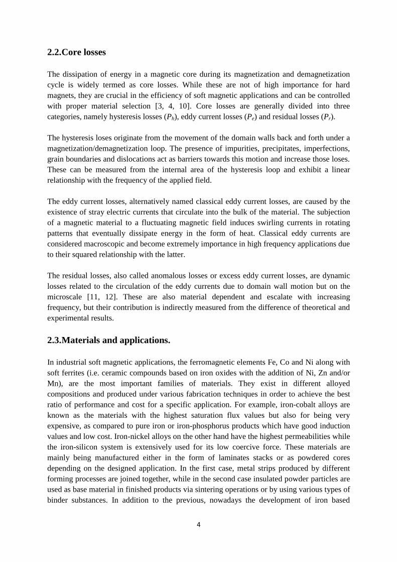
In Table 1 some of the most commonly used soft magnetic materials are mentioned along with
representative production techniques and applications.
Alloys Production
Techniques Properties Applications References
Pure Fe powdered
(SMC/sintered)
good saturation flux
/low cost
filters/pure inductors
/power transformers
/sensors/actuators
/electric motors
[2-4, 13-15]
Fe-P powdered
(sintered)
good saturation
/good mechanical
properties/low cost
pure inductors
/power transformers
/rotary actuators/sensors
[2, 4, 16,
17]
Fe-Si
laminated
/thin tapes
/powdered
(sintered)
good electrical
resistivity
/stability with age
/good mechanical
properties/low cost
pure inductors
/power transformers
/relays/solenoids
[2-4, 14,
16, 17]
Fe-Ni
thin tapes
/powdered
(sintered)
high permeability
/low flux density
/high cost
pure inductors
/power transformers
/actuators/detectors
/sensors/contractors
[2-4, 14,
16, 17]
Fe-Ni-Mo powdered
(sintered)
high permeability
/stability with time
and temperature
/high cost
loading coils/filtering
coils/switching power
supplies
[2, 3, 14]
Fe-Co
laminated
/powdered
(sintered)
high saturation
flux/high cost
actuators/
aerospace motors/
high performance
transformers/filters
[2, 4, 14,
16]
Soft ferrites
laminated
/powdered
(sintered)
high resistivity
/low saturation flux
/low cost
power transformers/filter
inductors/sensors
[2, 3, 14,
16]
Fe-B-Si
laminated
/powdered
high magnetic
permeability
/good saturation flux
/ high resistivity
high frequency aerospace
transformers
[2, 3, 18,
19]
Fe-Co-Si
Fe-Cu-Si
Fe-C-P-B-Si-Mo
Fe-B-Si-Nb
Fe-P-B-Si
Table 1: General classification of soft magnetic materials based on their composition,
production techniques, properties and applications.

6
7
3. Soft magnetic Composites
In this section of the thesis, the concept soft magnetic composite materials is presented along
with information on their processing and treatments.
3.1. Overview
Development of soft magnetic products for electromagnetic applications produced by
conventional powder metallurgical techniques is a continuous growing field [2, 4, 5, 11, 13-
17, 20]. These can be generally divide into two families, the ones produced by sintering of the
base powdered material into finalized components and the ones who do not need sintering but
the bonding is facilitated by the presence of various types of binding materials. In the first
family belong the iron based alloys described in the previous section which are targeted for
DC applications of less than 50Hz, exhibiting high saturation flux and good mechanical
properties [4, 17, 21]. The second family, which is known as Soft Magnetic Composites
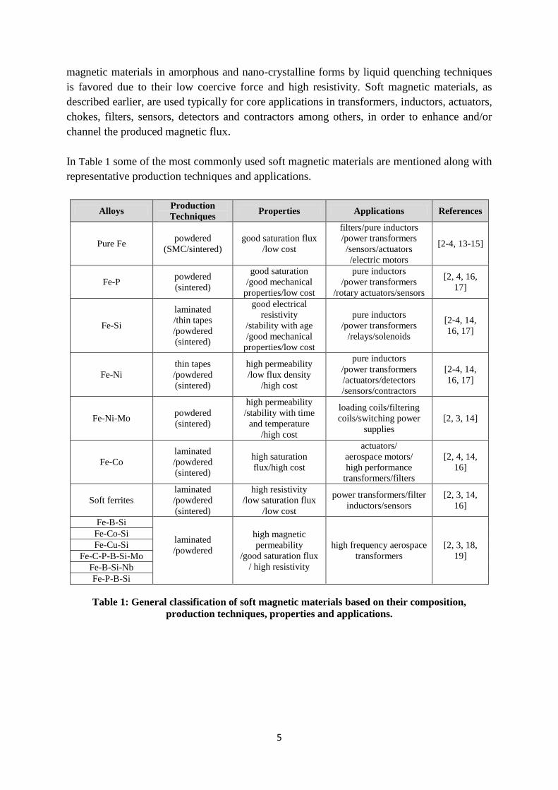
(SMC), considers powdered parts that consist of individually encapsulated pure iron powder
particles with an electrically insulating coating, bonded together in three dimensional
structures (Figure 2) [5, 15, 20].
Figure 2: The SMC concept.
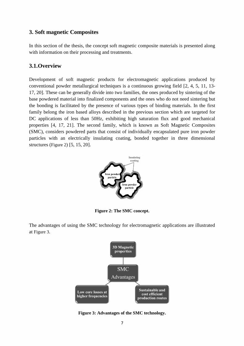
The advantages of using the SMC technology for electromagnetic applications are illustrated
at Figure 3.
Figure 3: Advantages of the SMC technology.
8
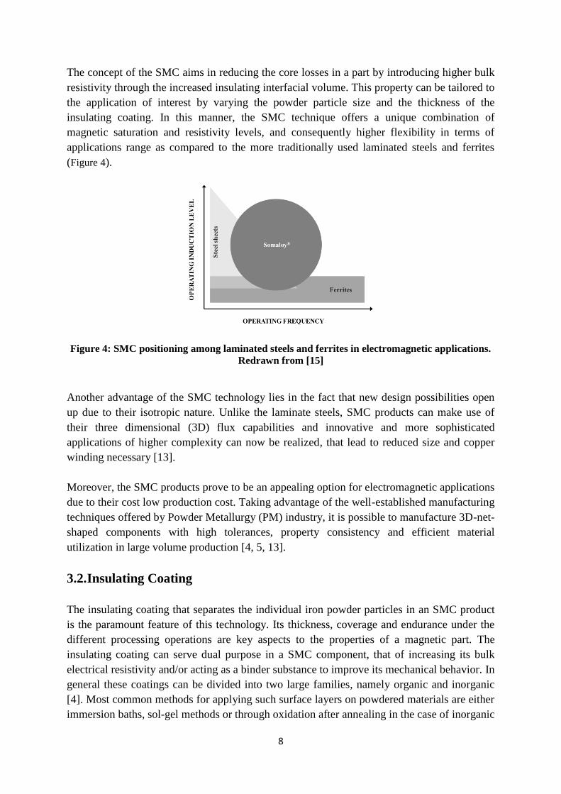
The concept of the SMC aims in reducing the core losses in a part by introducing higher bulk
resistivity through the increased insulating interfacial volume. This property can be tailored to
the application of interest by varying the powder particle size and the thickness of the
insulating coating. In this manner, the SMC technique offers a unique combination of
magnetic saturation and resistivity levels, and consequently higher flexibility in terms of
applications range as compared to the more traditionally used laminated steels and ferrites
(Figure 4).
Figure 4: SMC positioning among laminated steels and ferrites in electromagnetic applications.
Redrawn from [15]
Another advantage of the SMC technology lies in the fact that new design possibilities open
up due to their isotropic nature. Unlike the laminate steels, SMC products can make use of
their three dimensional (3D) flux capabilities and innovative and more sophisticated
applications of higher complexity can now be realized, that lead to reduced size and copper
winding necessary [13].
Moreover, the SMC products prove to be an appealing option for electromagnetic applications
due to their cost low production cost. Taking advantage of the well-established manufacturing
techniques offered by Powder Metallurgy (PM) industry, it is possible to manufacture 3D-net-
shaped components with high tolerances, property consistency and efficient material
utilization in large volume production [4, 5, 13].
3.2. Insulating Coating
The insulating coating that separates the individual iron powder particles in an SMC product
is the paramount feature of this technology. Its thickness, coverage and endurance under the
different processing operations are key aspects to the properties of a magnetic part. The
insulating coating can serve dual purpose in a SMC component, that of increasing its bulk
electrical resistivity and/or acting as a binder substance to improve its mechanical behavior. In
general these coatings can be divided into two large families, namely organic and inorganic
[4]. Most common methods for applying such surface layers on powdered materials are either
immersion baths, sol-gel methods or through oxidation after annealing in the case of inorganic
9
coatings, while dissolving, mixing and drying, or polymerization on the powder’s surface are
the most preferred routes for organic coatings [6-8, 22-25].
The latter have been used extensively in powdered cores and can be divided into
thermosetting and thermoplastic categories [4]. They are preferred due to the fact that they
can act as binder medium and introduce good physical strength to a part, though they cannot
be used in large volumes due to the reduction in permeability that they impose. A significant
drawback for the organic coating usage is their thermal stability, especially for thermosetting
resins, that does not allow an SMC part to be adequately stress relived at sufficient high
enough temperatures for hysteresis losses reduction [23]. On the other hand, thermoplastic
resins offer improved stability but have poorer coverage over the surface of the powder
particles due to the difficulties in handling and processing.
The most common type of inorganic coatings used in the SMC technology are the phosphates
(Zn/Fe/Mn), followed by oxides and sulfates [4]. Phosphatizing is a well establish metal
conversion method and it has been used extensively in the steel industry [26]. Their robust
application methods for large scale volume productions render them ideal for industrial usage.
Phosphate based coatings possess an attractive combination of properties by providing good
electrical insulation, anti-corrosive properties, thermal stability and can be functionalized and
upgraded to more complex and improved structures [7, 8, 24, 25, 27].
3.3. Processing of SMC materials
An SMC part has to go through different processing steps in a production line in order to
acquire its desired final form and properties. It should be understood that the combination of
the base material choice and that of the processing parameters provides with a range of
properties that can be tailored made for a desired application. It is obvious that these two are
linked and the behavior and properties of the selected materials under the different processing
steps will dictate the limits of the technique.
The manufacturing procedure of an SMC part via conventional PM production techniques
starts with the base material selection. In most cases pure iron or a low alloyed iron-based
powders containing Si, Ni, Al or Co and of various particle size distributions, typically
produced by traditional water atomization techniques, are used [4, 5]. These grades are
subsequently coated with the insulating surface layer, mixed with a lubricant and/or binder,
compressed under uniaxial high pressures (up to 800 MPa) at net-shaped bodies and then
subjected to post heat-treatment process, typically below 700°C [4].
The importance of the powder particle size, insulating coating and binder substance to the
properties of an SMC part were mentioned earlier. The effect of lubricant is also important for
the performance of a finished SMC component since it reduces inter-particles and particle to
die wall frictions during compaction process, which can be proven detrimental to the
coating’s quality. The downside though of lubricant usage can be that the by-products
produced during its degradation during the burn-off stage in the post heat-treatment process,

10
could also affect the nature of the coating by creating locally strong reducing atmospheres [9].
Moreover, an increased volume of the lubricant in a part has an inverse effect to its
permeability and maximum flux density [11].
Under compaction process the SMC products are brought close to their final shape in as much
less steps as possible, while at the same time higher density values are targeted which are
essential for acquiring higher induction values. The process though introduces residual
stresses to their bulk as well as high probability of damaging the insulating layer. These
effects reduce the core losses of the component substantially by increasing the hysteresis and
eddy current losses respectively [4, 11]. Different compaction techniques can be applied in
order to get optimal results. These include warm compaction (where both the powder and the
tool are heated), room temperature compaction, controlled die temperature compaction (where
only the tool is heated up), two step compaction and high velocity compaction [4, 28].
To minimize the effect of the cold work imposed on an SMC part during its compaction, and
subsequently to improve its properties, a post heat-treatment is required. Additionally, this
step is required for the curing purposes when a binder is added, usually at lower temperatures
[23]. The stress relief is a time-temperature related phenomenon and in principle, higher
temperature regimes or longer dwelling times are needed for better tuning a component’s
properties. The time-temperature recipe though for a post heat-treatment step, as well as under
which type of atmosphere this should take place, are largely dependent on the viability of the
insulating layer during its process [9, 28]. It is thus crucial in the SMC technology that no
sintering and no reduction of the coating should take place, since that would mean that its
integrity been compromised and higher eddy current losses will achieved.
11
4. Materials and experimental details
For the purpose of materials characterization and modeling development a combination of
complementary spectroscopic and microscopic analytical techniques were used. A detailed
description of the materials under question along with experimental details related to the
implementation of these techniques for such purposes is presented in the current section. The
schema provided below in Figure 5 outlines the experimental procedure followed in this thesis
and the materials used in every step.
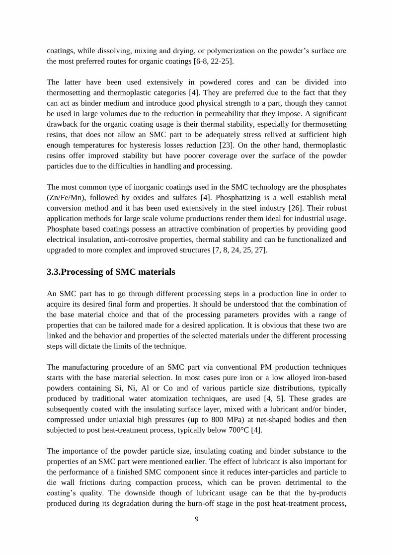
Figure 5: Schema of experimental investigations.
In this study two lines of experiments have been designed in order to reach its goals. In one of
these (depicted to the left hand side of Figure 5), pure iron powder grades were investigated in
Paper I as a base material for the development of the theoretical model for surface products
thickness determination using HR SEM, FIB and XPS techniques. In the other (depicted to
the right hand side of Figure 5), SMC as-received powder and finished components were
analyzed in Papers II and III using HR SEM, EDX and XPS techniques for material
characterization as well as process modeling and optimization purposes.
4.1. Materials
4.1.1. Pure iron powder
Pure iron powder produced by water atomization by Höganäs AB, Sweden, along with gas
atomized iron powder of the same composition from a pilot atomizer were used for the
experimental needs of the theoretical model development in Paper I. These grades have been
12
characterized elsewhere [29] based on their morphology, surface characteristics and
chemistry. The water atomized powder exhibits a characteristic irregular shape as opposed to
the spherical one of the gas atomized, while in both cases it was established that the surface
was covered by a nano-sized homogeneous iron oxide layer. In the present work, both grades
have been subject to further oxidation by heat treatment in air at 300°C prior to their analysis
in order to grow sufficient thick surface oxide extended above the 3λox
limit (where λox
is the
electron mean free path in the oxide layer) needed to implement the depth profiling technique
in the XPS and also beyond the resolution limit of the HR SEM technique. In addition, both
kinds of powder have been sieved down into a particle size fraction of 53-28 μm for
minimizing any shading effects imposed by the sample roughness during the XPS
investigations. The same powder fraction was also examined with focused ion beam (FIB)
and high resolution scanning electron microscopy (HR SEM) for consistency purposes.
4.1.2. Somaloy® 500 material
The available commercial SMC powder grade Somaloy® 500 produced by Höganäs AB,
Sweden, was used as a reference material. It consists of high purity water atomized iron
powder, less than 150 μm in size, as a core structure coated individually with an ultra-thin
inorganic electrically insulating surface layer under a patented process [22]. The powder was
analyzed both in as-received form and in finished SMC components of toroidal shape, having
5x5 mm cross section and outer/internal diameter dimensions of 55mm/45mm respectively.
The production of these parts for the current work included mixing of the SMC powder with
0.5 wt% of the commercial organic lubricant KenolubeTM
, compaction under conventional
uniaxial die pressing at 800 MPa and heat treatment at 400, 500 and 600°C in air for 30 min,
including de-lubrication and stress relief steps.
4.2. Analytical techniques
4.2.1. X-ray Photoelectron Spectroscopy
X-ray Photoelectron Spectroscopy (XPS) is a surface sensitive analytical technique that
provides chemical compositional and chemical state information of the investigated material
from a very small analysis depth of the order of few nanometers into the surface [30, 31].
Combined with ion etching technique it is possible to achieve depth profiling of the sample of
interest. These attributes of XPS as well as its sensitivity to chemical environment changes
(chemical peak shifts) and wide range of type of materials that can be examined makes it very
appealing for surface and interface analysis in material science [32].
This technique has been used extensively for analysis of flat surfaces [31, 32] with an
enormous amount of experimental methods and modeling efforts now available to the
researcher. On the contrary, it has not been so popular for surfaces of specific geometry and
roughness due to the anticipated shading effects from such samples and the subsequent
uncertainties that these bring to the results. Previously, a theoretical model for analyzing
13
spherical particles using depth profiling technique combined with XPS was developed and
experimentally tested by Nyborg et al. [33]. In their study, the effect of the surface geometry
of the sample on the photoelectron intensity, X-ray flux and ion sputter rate was formulated
for a specific experimental arrangement. By doing so, it was possible to evaluate the thickness
of a homogeneous surface layer on a powder sample with a core-shell structure using depth
profiling and by taking into account the normalized intensity of the substrate material at a
certain relative metallic intensity fraction, defined by the relationship of the thickness of the
layer over its attenuation length.
In this thesis, the XPS technique has been further implemented for developing the theoretical
model and also to investigate the surface chemistry of the SMC powder in as-received state
and finished components. In all cases a PHI 5500 (PERKIN ELMER, Eden Prairie,
Minnesota, USA) instrument was used for analysis, equipped with a monochromatic Al Kα
(1486.6 eV) X-ray source under ultra-high vacuum (UHV) conditions (1.3x10⁻¹²
bar). In the
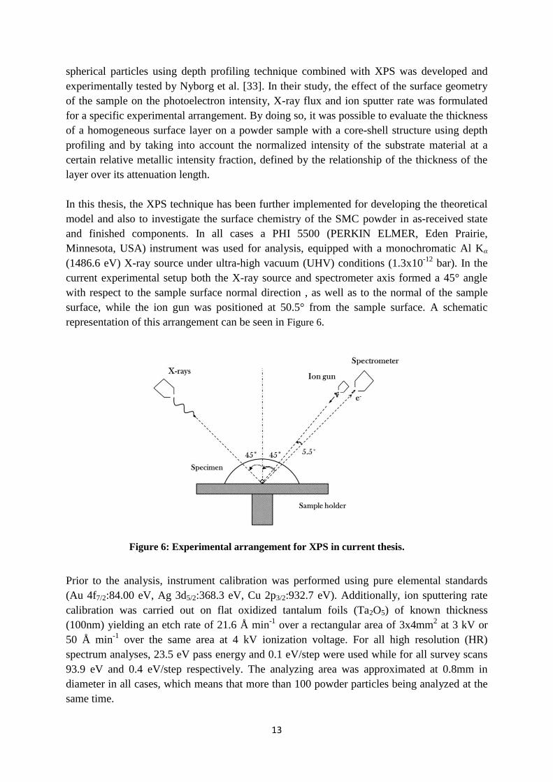
current experimental setup both the X-ray source and spectrometer axis formed a 45° angle
with respect to the sample surface normal direction , as well as to the normal of the sample
surface, while the ion gun was positioned at 50.5° from the sample surface. A schematic
representation of this arrangement can be seen in Figure 6.
Figure 6: Experimental arrangement for XPS in current thesis.
Prior to the analysis, instrument calibration was performed using pure elemental standards
(Au 4f7/2:84.00 eV, Ag 3d5/2:368.3 eV, Cu 2p3/2:932.7 eV). Additionally, ion sputtering rate
calibration was carried out on flat oxidized tantalum foils (Ta2O5) of known thickness
(100nm) yielding an etch rate of 21.6 Å min-1
over a rectangular area of 3x4mm2 at 3 kV or
50 Å min-1
over the same area at 4 kV ionization voltage. For all high resolution (HR)
spectrum analyses, 23.5 eV pass energy and 0.1 eV/step were used while for all survey scans
93.9 eV and 0.4 eV/step respectively. The analyzing area was approximated at 0.8mm in
diameter in all cases, which means that more than 100 powder particles being analyzed at the
same time.
14
The heat-treated SMC components where fractured prior to their analysis and both outer and
center regions of their cross sections were examined. The analyzed powder samples where
loosely mounted on double adhesive conductive carbon tape in order to prevent any further
deformation of the particles and ensure the integrity of the surface layers. The detected carbon
signal was used as a reference value (C1s: 285 eV) for charge compensation purposes. Due to
the high purity of the analyzed materials its presence was attributed to the existence of
adventitious hydrocarbons on the samples surface, both for components and as-received
powder. Charge compensation was performed in all cases using software correction and a low
energy electron charge neutralizer flood gun. In later sputtering depths, where needed, the
signal of the metallic iron was also used as a reference for charge peak shifting correction.
The analysis and curve fitting of the collected spectra was performed with PHI Multipack
software and for this an asymmetric Gaussian-Lorentzian line shape was preferred combined
with Shirley background subtraction.
4.2.2. High Resolution Electron Microscopy
For the needs of surface morphology characterization of both powder samples and
components, high resolution scanning electron microscopy (HR SEM) was implemented
using a LEO Gemini 1550 (CARL ZEISS - LEO electron microscopy, GmbH, Germany)
electron microscope equipped with a field emission gun. An in-lens secondary electron
detector built in the electron column of the microscope was preferred for such type of analysis
due to its high sensitivity at close working distances and low acceleration voltages, providing
superior topographic and material work function related information with high lateral
resolution. Energy dispersive X-ray spectroscopy (EDX) was also utilized as means of
complementary chemical microanalysis in Papers II and III with an INCAEnergy system,
though due to the inherent surface roughness of all samples the results were only evaluated
qualitatively. Calibration for the microanalysis was conducted using elemental standards of
cobalt for 20, 15 and 10 kV and silicon for 5kV. All powder samples were soft pressed into
aluminum plates for HR SEM and EDX analysis while no special preparation was needed for
the fractured surfaces of the components.
4.2.3. Focused Ion Beam
The focus ion beam (FIB) technique in combination with HR SEM were used in Paper I in
order to determine the homogeneity and thickness of the surface layers from both gas and
water atomized powder grades. The synergy of these techniques provides the user with the
opportunity of performing in-depth analysis on sub-surfaces from exposed cross sectional
regions created through a series of cutting and imaging of the material. This is achieved by
having a dual beam system focused on the sample, consisting of an ion beam for sputtering
and electron beam for imaging purposes. In this thesis a FEI Versa 3D DualBeam FIB–SEM
station was used, equipped with a field emission gun (FEG) source and gallium high-current
liquid metal ion source. Prior to the sputtering operations the samples where first gold coated
before they were introduced to the station with an Edwards Sputter coater S150B and
15
subsequently a platinum layer of 2μm thickness was deposited on the site of interest in situ
with an Omniprobe micromanipulator needle in order to protect the surface layer and achieve
a sharp interface. The ion sputtering was carried out with gallium ions of 2 to 30 keV energy
and 27 to 65000 pA beam current until the desired cross sectional surface quality was
acquired. The samples were prepared by soft pressing the powder grades into aluminum plates
similarly to the HR SEM analysis.
4.2.4. X-ray Diffraction
In the present work, the X-ray diffraction was used for phase identification analysis of the
exterior surface of SMC heat treated components at different temperature regimes. The
experimental measurements were carried out using a Bruker D8 ADVANCE diffractometer
equipped with a Cr-Kα source under grazing angle mode at an incident angle of 3 degrees
over a range of 40° < 2θ <140° with 0.05° 2θ/step and 5 sec/step. The penetration depths of
the X-rays for the compounds of interest were calculated with the AbsorbDX V.1.1.4
software.

16
17
5. Results and summary of appended papers
In this section of the thesis the results and a summary of the appended papers are given, along
with key discussion points and some complementary material to better illustrate all of the
above where needed. In Paper I the further development of the existing theoretical model [33]
for estimating the thickness of homogeneous surface layers on substrates of spherical shape
using depth profiling technique with XPS was presented. The model’s formulation was
introduced and its validity was experimentally assessed using XPS on pure iron powder
grades of regular and irregular morphologies. Additional analytical techniques such as FIB –
HR SEM were also implemented for confirmation of the results. In Papers II and III the SMC
as-received powder and finished components, respectively, were analyzed. In the first case a
methodology was developed based on XPS, HR SEM and EDX techniques for chemical,
topological/morphological and depth profiling analysis of such type of insulating layers.
Different sample preparation and charge compensation methods were tested and optimum
conditions for imaging and chemical analysis were established. In the second case, SMC
finished components were investigated using HR SEM, EDX, XPS and XRD techniques. The
effect of the temperature to the different regions of a part and to the thermal stability of the
surface insulating coating was evaluated.
5.1. Theoretical model development for layer thickness determination on
powder
The experimental arrangement influences the result of an XPS depth profiling analysis when
this regards materials of specific geometry and roughness. As opposed to flat surfaces,
inherent shading effects can be introduced and influence the result due to their irregular
morphologies. Additionally, the X-ray flux, photoelectron intensity and ion sputter rate are
not constant locally when probing such type of surface irregularities but exhibit an angle
dependency over the whole analyzed surface area. In particular, this type of dependency of
the ion sputtering rate results in non-homogeneous material removal over the probed area and
the positioning of the ion gun in space in respect to the spectrometer and to the X-ray source
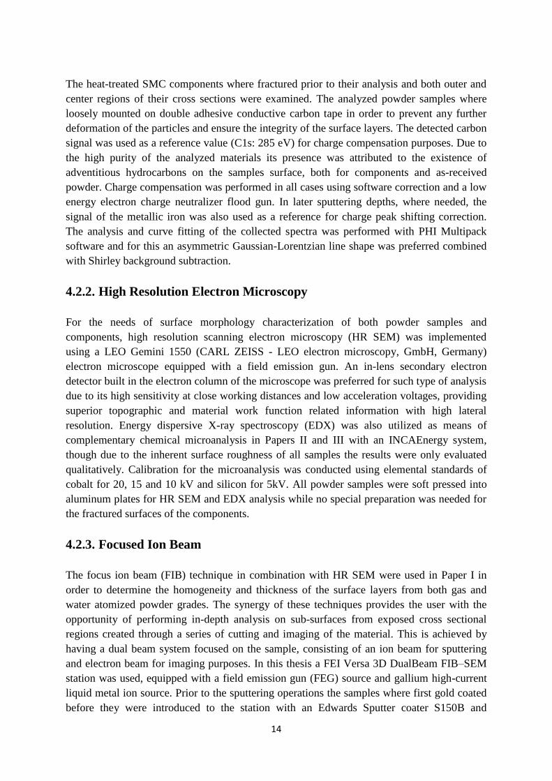
dictates the amount of residual layer that will be analyzed. In Figure 7 an attempt to illustrate
this effect is shown for the case of a spherical core-shell structure (the dashed interior sphere
represents the core while the yellow colored exterior sphere the homogeneous surface layer)
examined with an arbitrary experimental setup. There, the residual surface layer (colored in
orange) that will be measured from the analyzed area (dark shaded region) depends on the
position of the ion gun in the three dimensional space.
18
Figure 7: A schematic illustration of the effect of the incident ion beam angle on the analysis of a
spherical surface with XPS.
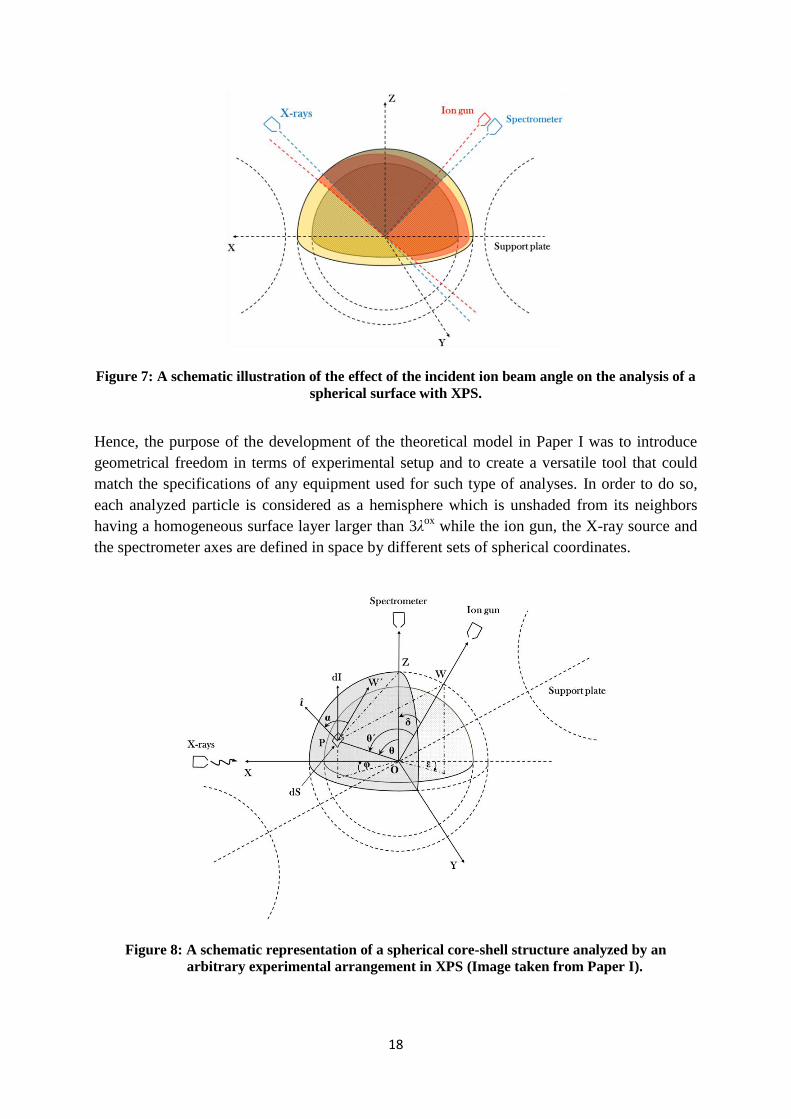
Hence, the purpose of the development of the theoretical model in Paper I was to introduce
geometrical freedom in terms of experimental setup and to create a versatile tool that could
match the specifications of any equipment used for such type of analyses. In order to do so,
each analyzed particle is considered as a hemisphere which is unshaded from its neighbors
having a homogeneous surface layer larger than 3λox
while the ion gun, the X-ray source and
the spectrometer axes are defined in space by different sets of spherical coordinates.
Figure 8: A schematic representation of a spherical core-shell structure analyzed by an
arbitrary experimental arrangement in XPS (Image taken from Paper I).
19
In Figure 8, the spherical coordinates of a random point P on the analyzed area of a particle
surface (shaded area) are depicted as well as the relationships between the X-ray source, the
spectrometer and the ion gun. All these considerations where taken into account in Paper I
and a relationship that defined the recorded intensity at each point of interest was formulated
according to equation (1):
∫ ∫
(1)
The latter, along with a profile for the angle effect on the sputtering rate, were implemented in
order to calculate the residual surface layer (tox
) at every point P of the analyzed area. These
calculations were carried out utilizing an iterative process in a custom developed computer
software for which only the experimental and material dependent parameters mentioned
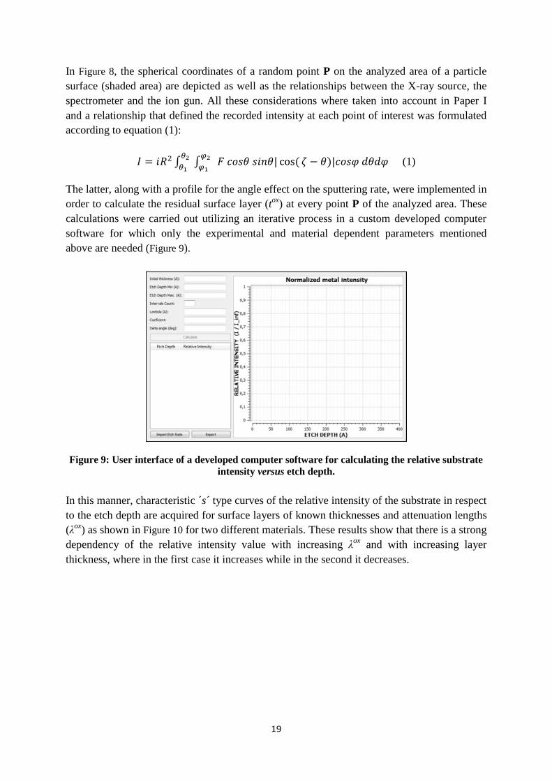
above are needed (Figure 9).
Figure 9: User interface of a developed computer software for calculating the relative substrate
intensity versus etch depth.
In this manner, characteristic ´s´ type curves of the relative intensity of the substrate in respect
to the etch depth are acquired for surface layers of known thicknesses and attenuation lengths
(λox
) as shown in Figure 10 for two different materials. These results show that there is a strong
dependency of the relative intensity value with increasing λox
and with increasing layer
thickness, where in the first case it increases while in the second it decreases.
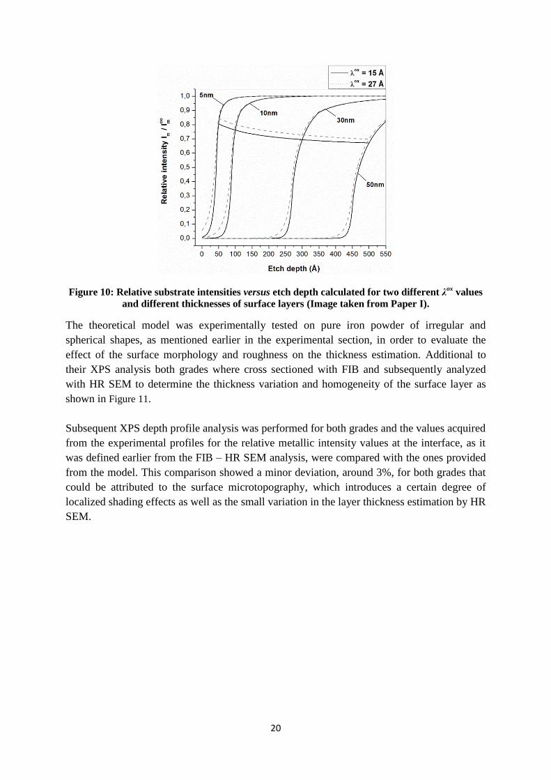
20
Figure 10: Relative substrate intensities versus etch depth calculated for two different λox
values
and different thicknesses of surface layers (Image taken from Paper I).
The theoretical model was experimentally tested on pure iron powder of irregular and
spherical shapes, as mentioned earlier in the experimental section, in order to evaluate the
effect of the surface morphology and roughness on the thickness estimation. Additional to
their XPS analysis both grades where cross sectioned with FIB and subsequently analyzed
with HR SEM to determine the thickness variation and homogeneity of the surface layer as
shown in Figure 11.
Subsequent XPS depth profile analysis was performed for both grades and the values acquired
from the experimental profiles for the relative metallic intensity values at the interface, as it
was defined earlier from the FIB – HR SEM analysis, were compared with the ones provided
from the model. This comparison showed a minor deviation, around 3%, for both grades that
could be attributed to the surface microtopography, which introduces a certain degree of
localized shading effects as well as the small variation in the layer thickness estimation by HR
SEM.
21
Figure 11: Analyzed cross sections of powder particles from both grades with FIB – HR SEM
5.2. Characterization of SMC powder
To characterize the initial state/composition of the insulating coating of the SMC material, a
robust methodology needed to be established based on analytical techniques. Initially, the as-
received SMC powder was investigated with HR SEM and EDX with different experimental
settings in order to determine the optimal conditions for evaluating the coatings morphology,
cohesion and coverage of the surface. A range of acceleration voltages from 5 to 20 kV and
aperture sizes of 30μm or less were tested in Paper II as to efficiently enough reduce the beam
spot size and interaction volume. The results are shown in Figure 12 where it can be observed
that with increasing acceleration voltage, due to the higher energy of the secondary electrons
emitted, the information acquired from the very top surface is significantly less and the
features of the coating are no longer visible. Additionally, regarding the chemical
microanalysis, it is shown that at lower acceleration voltage it is possible to still excite all the
elements present at the surface layer and better distinguish between the core material and the
coating regions. By implementing the above optimum conditions, HR SEM and EDX analysis
revealed the good coverage of the insulating layer over the particles surface, its homogeneity
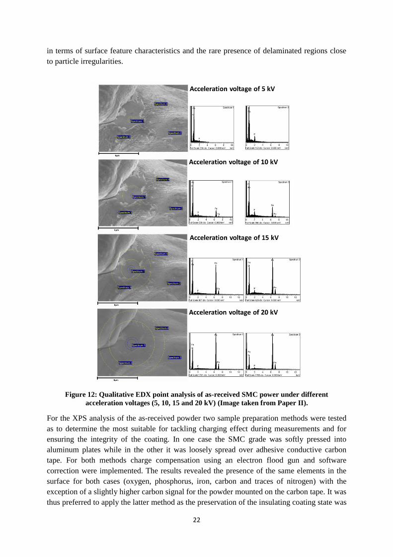
22
in terms of surface feature characteristics and the rare presence of delaminated regions close
to particle irregularities.
Figure 12: Qualitative EDX point analysis of as-received SMC power under different
acceleration voltages (5, 10, 15 and 20 kV) (Image taken from Paper II).
For the XPS analysis of the as-received powder two sample preparation methods were tested
as to determine the most suitable for tackling charging effect during measurements and for
ensuring the integrity of the coating. In one case the SMC grade was softly pressed into
aluminum plates while in the other it was loosely spread over adhesive conductive carbon
tape. For both methods charge compensation using an electron flood gun and software
correction were implemented. The results revealed the presence of the same elements in the
surface for both cases (oxygen, phosphorus, iron, carbon and traces of nitrogen) with the
exception of a slightly higher carbon signal for the powder mounted on the carbon tape. It was
thus preferred to apply the latter method as the preservation of the insulating coating state was
23
much more ensured as no mechanical force was applied on the particles during specimen
preparation. The chemical compositional analysis of the powder with the HR scans showed
that the surface layer consists of ferric and ferrous iron phosphate compounds. The stability of
the phosphorus signal to the sputtering operations indicated its homogeneous nature
throughout coating’s depth. Moreover, the analysis of the oxygen signal after successive ion
sputtering steps exposed a transition from the group to the ompound, which
accounted to the oxide Fe2O3 close to the interface between the matrix and the surface layer.
The implementation of the model for layer thickness determination to the as-received powder
was also performed based on the XPS depth profiling analysis and the thickness evaluation of
the surface layer was estimated based on the normalized signals of its constituent elements
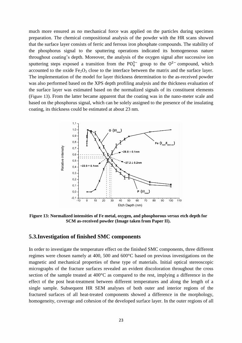
(Figure 13). From the latter became apparent that the coating was in the nano-meter scale and
based on the phosphorus signal, which can be solely assigned to the presence of the insulating
coating, its thickness could be estimated at about 23 nm.
Figure 13: Normalized intensities of Fe metal, oxygen, and phosphorous versus etch depth for
SCM as-received powder (Image taken from Paper II).
5.3. Investigation of finished SMC components
In order to investigate the temperature effect on the finished SMC components, three different
regimes were chosen namely at 400, 500 and 600°C based on previous investigations on the
magnetic and mechanical properties of these type of materials. Initial optical stereoscopic
micrographs of the fracture surfaces revealed an evident discoloration throughout the cross
section of the sample treated at 400°C as compared to the rest, implying a difference in the
effect of the post heat-treatment between different temperatures and along the length of a
single sample. Subsequent HR SEM analyses of both outer and interior regions of the
fractured surfaces of all heat-treated components showed a difference in the morphology,
homogeneity, coverage and cohesion of the developed surface layer. In the outer regions of all
24
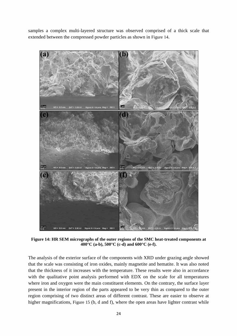
samples a complex multi-layered structure was observed comprised of a thick scale that
extended between the compressed powder particles as shown in Figure 14.
Figure 14: HR SEM micrographs of the outer regions of the SMC heat-treated components at
400°C (a-b), 500°C (c-d) and 600°C (e-f).
The analysis of the exterior surface of the components with XRD under grazing angle showed
that the scale was consisting of iron oxides, mainly magnetite and hematite. It was also noted
that the thickness of it increases with the temperature. These results were also in accordance
with the qualitative point analysis performed with EDX on the scale for all temperatures
where iron and oxygen were the main constituent elements. On the contrary, the surface layer
present in the interior region of the parts appeared to be very thin as compared to the outer
region comprising of two distinct areas of different contrast. These are easier to observe at
higher magnifications, Figure 15 (b, d and f), where the open areas have lighter contrast while
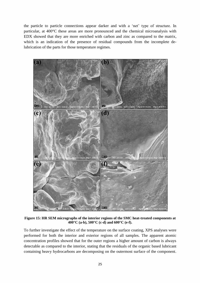
25
the particle to particle connections appear darker and with a ‘net’ type of structure. In
particular, at 400°C these areas are more pronounced and the chemical microanalysis with
EDX showed that they are more enriched with carbon and zinc as compared to the matrix,
which is an indication of the presence of residual compounds from the incomplete de-
lubrication of the parts for those temperature regimes.
Figure 15: HR SEM micrographs of the interior regions of the SMC heat-treated components at
400°C (a-b), 500°C (c-d) and 600°C (e-f).
To further investigate the effect of the temperature on the surface coating, XPS analyses were
performed for both the interior and exterior regions of all samples. The apparent atomic
concentration profiles showed that for the outer regions a higher amount of carbon is always
detectable as compared to the interior, stating that the residuals of the organic based lubricant
containing heavy hydrocarbons are decomposing on the outermost surface of the component.
26
Moreover, the carbon content in the fracture surface of the interior region of the sample
treated at 400°C was also higher as compared to the rest samples, showing that the incomplete
de-lubrication is even more evident at that regime. The HR XPS spectrum analysis of all
surface layers, for both regions, indicated that they consist mainly of a mixture of iron oxides
and iron phosphates of both divalent and trivalent forms. In particular, the oxygen signal
analysis at 400°C showed the oxidation was more pronounced in both regions compared to
the rest samples. This result coupled well with those from the imaging and XRD analysis and
it was concluded that the insufficient closure of the external porosity from the oxide scale
growth at low temperatures lead to the extended oxidation of the component throughout its
cross section.
By further analyzing the HR XPS spectra, a small secondary peak after ion sputtering was
observed for all temperatures in the phosphorus signal. Its presence was not attributed to the
species but to transitional metal phosphides. Theoretical thermodynamic calculations
performed in Paper III supported their existence close to the interfacial region between the
surface layer and the matrix due to the abundance of iron and the low oxygen partial pressure
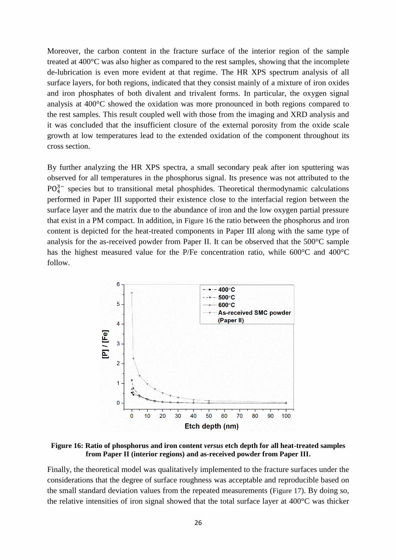
that exist in a PM compact. In addition, in Figure 16 the ratio between the phosphorus and iron
content is depicted for the heat-treated components in Paper III along with the same type of
analysis for the as-received powder from Paper II. It can be observed that the 500°C sample
has the highest measured value for the P/Fe concentration ratio, while 600°C and 400°C
follow.
Figure 16: Ratio of phosphorus and iron content versus etch depth for all heat-treated samples
from Paper II (interior regions) and as-received powder from Paper III.
Finally, the theoretical model was qualitatively implemented to the fracture surfaces under the
considerations that the degree of surface roughness was acceptable and reproducible based on
the small standard deviation values from the repeated measurements (Figure 17). By doing so,
the relative intensities of iron signal showed that the total surface layer at 400°C was thicker
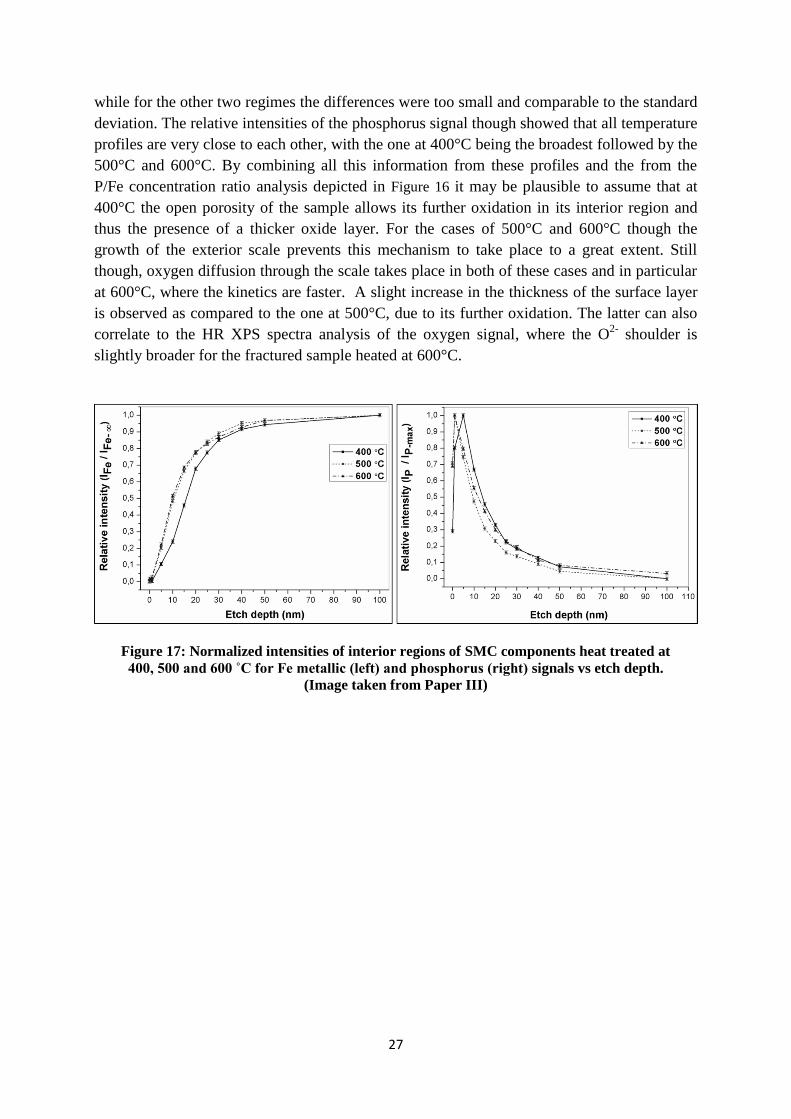
27
while for the other two regimes the differences were too small and comparable to the standard
deviation. The relative intensities of the phosphorus signal though showed that all temperature
profiles are very close to each other, with the one at 400°C being the broadest followed by the
500°C and 600°C. By combining all this information from these profiles and the from the
P/Fe concentration ratio analysis depicted in Figure 16 it may be plausible to assume that at
400°C the open porosity of the sample allows its further oxidation in its interior region and
thus the presence of a thicker oxide layer. For the cases of 500°C and 600°C though the
growth of the exterior scale prevents this mechanism to take place to a great extent. Still
though, oxygen diffusion through the scale takes place in both of these cases and in particular
at 600°C, where the kinetics are faster. A slight increase in the thickness of the surface layer
is observed as compared to the one at 500°C, due to its further oxidation. The latter can also
correlate to the HR XPS spectra analysis of the oxygen signal, where the O2-
shoulder is
slightly broader for the fractured sample heated at 600°C.
Figure 17: Normalized intensities of interior regions of SMC components heat treated at
400, 500 and 600 ˚C for Fe metallic (left) and phosphorus (right) signals vs etch depth.
(Image taken from Paper III)

28
29
6. Conclusions
In the present study, the following concluding remarks can be highlighted:
Theoretical model for thickness evaluation of surface coatings on metal powder
A theoretical model for estimating the thickness of surface layers on particles of spherical
shape using XPS depth profiling technique without any geometrical constraints related to
the experimental arrangement has been developed.
The model was experimentally tested with XPS and validated using XPS and FIB - HR
SEM analytical techniques and the deviation between theoretical and experimental values
was of the order of 3%.
It is possible to apply the model with good agreement for routine measurements on
surfaces of specific geometry and roughness in the range of up to hundred micrometers.
Methodology development for surface analysis of SMC powder
A methodology was developed for the evaluation of the composition, morphology and
thickness of the insulating layer of SMC powder grades.
Optimum conditions for HR SEM and EDX analysis were defined at 5kV acceleration
voltage and low beam current using in-lens secondary electron detector.
Adhesive carbon tape was evaluated as the optimal method for sample preparation for
XPS analysis.
Analysis reveals oxygen, iron, and phosphorous as the main constituents of the insulating
coating.
The surface coating was found to be stable under ion sputtering operations.
Coating thickness evaluation based on the normalized intensities of the metallic iron,
phosphorus and oxygen signals show that it ranges bellow 30nm.
Heat-treatment of SMC components
The effect of temperature on the surface layer morphology, homogeneity, cohesion and
composition was evaluated using XPS, HR SEM, EDX and XRD techniques for SMC
finished components.
For all temperatures two regions, an exterior and an interior, can be distinguished having
significant differences in the degree of oxidation.
For all temperatures the exterior region appears to be considerably oxidized and the
presence of an iron oxide scale that increases in thickness with temperature was confirmed
as the dominant surface constituent.
Analysis of all interior regions revealed the presence of a blend of iron phosphates and
iron oxides both in divalent and trivalent form.
The presence of impurity oxide particulates and iron phosphide precipitates dispersed in
the insulating surface layer were confirmed as a result of the post heat treatment.
HR-SEM, EDX and XPS analyses showed the presence of higher amounts of lubricant
residuals enriched in Zn due to the incomplete de-lubrication process for the interior
region of the sample treated at 400°C.

30
Qualitative implementation of a theoretical model for surface layer thickness
determination based on XPS depth profiling showed for 400°C that the insulating layer is
associated with a broader profile, i.e. more extended presence along the etch depth, which
can be attributed to stronger presence of iron oxides.
31
7. Suggestions for future work
7.1. Theoretical model development
For further experimental validation of the theoretical model, point analysis with the auger
electron spectroscopy (AES), as well as transmission electron microscopy (TEM) and electron
backscatter diffraction (EBSD) on powder particle cross sections can be utilized in order to
fully characterize the materials under investigation and so to eliminate any ambiguities in
regard to their thickness evaluation.
Furthermore, the theoretical model is possible to be extended to surfaces of higher roughness,
e.g. fracture surfaces, and acquire quantitative results. In order to do so, it must be combined
with methods or techniques that provide quantification of roughness on a micro level, e.g.
MeX for SEM, and evaluated experimentally on fully characterized materials with
complementary analytical techniques.
7.2. SMC analysis
Complementary results to the ones acquired from the analysis of the SMC heat-treated
components can yield heat-treatments on the as-received powder alone. By doing so, the
effect the lubricant present can be eliminated and additionally the theoretical model could
provide quantification of the coating’s thickness determination.
Moreover, additional analysis by AES on the fractured surfaces could reveal more
information on the nature of the phosphide phases present as well as information on the
composition and thickness of the coating between particle to particle contacts and open (pore
surface) areas.

32

33
8. Acknowledgments
I would like to thank and express my deepest gratitude and admiration for both my supervisor
Professor Lars Nyborg and co-supervisor Associate Professor Eduard Hryha. I consider
myself very fortunate for having the opportunity to be close and received guidance from two
very intelligent men. I hope that my efforts are showing that you are doing a good job!
Höganäs ΑΒ in Sweden is highly acknowledged for providing with financial support and
materials for this study. In particular, I would like to thank all of the people in the
ElectroMagnetic Applications and especially Dr. Zhou Ye and Dr. Ann-Cathrin Hellsén for
their contribution.
The Swedish Energy Agency and the Chalmersska forskningsfonden are also highly
acknowledged for providing financial support for the needs of this study.
My many thanks to Urban Jelvestam and Dr. Eric Tam for all their help and especially when
XPS was misbehaving (even during weekends!).
Dr. Yiming Yao is highly acknowledged for her contribution and inputs in this work and all
the personnel in the Materials and Manufacturing Department that helped me in any way.
Many special thanks to Dr. Raquel De Oro Calderón for her support and occasional therapy
sessions! This thesis owes her a lot!
Dimitris Nikas for providing a great master thesis, as well as my colleagues Seshendra
Karamchedu and current office roommate Giulio Maistro are all acknowledged for helping
me finishing this project.
I would like to send out my most special thanks and gratitude to my former office roommate
and friend Dr. Dimitris Chasoglou for his genuine support, help and friendship both in and out
of Chalmers!
I would like to express my most sincere gratitude and love for all my friends and colleagues
both in Sweden and in Greece! All of you around me helped more than you can imagine!
Extra special thanks to Amir Malakizadi, Kumar Babu Surreddi, Dr. Ruth Ariño Marine, Esaú
Poblador, Erik Stenvall, Dinesh Mallipeddi, Stefan Cerdegren, Johannes Erik Balatsos,
Christos Doulgerakis, Sofia Poulikidou, Dionisis and Elin Logara!
Last but not least, I would like to dedicate this effort of mine to my family in Greece and
especially my beloved parents Nikolaos and Maria Oikonomou. I am not good enough in
words to express how much I think of you.

34
35
9. References
[1] Energy efficiency and specific CO2 emissions, Retrieved March 27, 2014,
http://www.eea.europa.eu/data-and-maps/indicators/energy-efficiency-and-specific-co2-
emissions
[2] O. Gutfleisch, M.A. Willard, E. Bruck, C.H. Chen, S.G. Sankar, J.P. Liu, Magnetic
materials and devices for the 21st century: stronger, lighter, and more energy efficient,
Advanced materials, 23, 7, (2011) 821-842.
[3] W.T. McLyman, Transformer and Inductor Design Handbook - Fourth Edition, Taylor
and Francis Group, LLC, (2011)
[4] H. Shokrollahi, K. Janghorban, Soft magnetic composite materials (SMCs), Journal of
Materials Processing Technology, Vol. 189, No. 1-3, (2007) 1-12.
[5] M. Persson, P. Jansson, A.G. Jack, B.C. Mecrow, Soft Magnetic Composite Materials -
Use for Electrical Machines, IEEE Conference Publication, No. 412, (1995), 242-246.
[6] H. Bruncková, M. Kabátová, E. Dudrová, The effect of iron phosphate, alumina and silica
coatings on the morphology of carbonyl iron particles, Surface and Interface Analysis, Vol.
42, No. 1, (2010) 13-20.
[7] A.H. Taghvaei, H. Shokrollahi, K. Janghorban, H. Abiri, Eddy current and total power
loss separation in the iron–phosphate–polyepoxy soft magnetic composites, Materials &
Design, Vol. 30, No. 10, (2009) 3989-3995.
[8] S. Wu, A. Sun, W. Xu, Q. Zhang, F. Zhai, P. Logan, A.A. Volinsky, Iron-based soft
magnetic composites with Mn–Zn ferrite nanoparticles coating obtained by sol–gel method,
Journal of Magnetism and Magnetic Materials, Vol. 324, No. 22, (2012) 3899-3905.
[9] P. Jansson, Processing aspects of soft magnetic composites, Proceedings of the Euro
PM2000 Conference Soft Magnetic Materials Workshop, Munich, Germany, (2000), 9-14.
[10] B.D. Cullity, C.D. Graham, Introduction to Magnetic Materials, Second Edition, IEEE
Press, (2009)
[11] H. Skarrie, Design of Powder Core Inductors, Lund University, Sweden, (2001).
[12] Y. Zhang, M.-C. Cheng, P. Pillay, Magnetic Characteristics and Excess Eddy Current
Losses, Proccedings IEEE Industry Applications Society Annual Meeting, (2009), 1-5.
[13] L.O. Hultman, A.G. Jack, Soft Magnetic Composites - Materials and Applications,
Electric Machines and Drives Conference, IEMDC’03, IEEE International, Vol. 1, (2003),
516-522.
[14] ARNOLD Magnetic Technologies, Soft Magnetics Applications Guide, Retrieved March
29, 2014, http://www.arnoldmagnetics.com/Soft_Magnetics_Applications_Guide.aspx
[15] Höganäs AB. Somaloy Technology, Applications, Retrieved March 29, 2014,
http://www.hoganas.com/en/Segments/Somaloy-Technology/Applications/
36
[16] AMES, Soft Magnetic Parts, Retrieved March 29, 2014,
http://www.ames.es/products/1037-2/
[17] K. Narasimhan, F. Hanejko, M.L. Marucci, Soft magnetic material for A.C. applications,
Hoeganes Corporation, Available from
http://www.yunamedia.com/GKNPLCHC.com/KyungHoeganae/TechPapersv2/201.pdf.
[18] O. Larsson, Fe-based Amorphous Powder for Soft-Magnetic Composites, Department of
Materials Science and Engineering, Royal Institute of Technology, Stockholm, Sweden,
Master Thesis, (2013).
[19] C. Suryanarayana, A. Inoue, Iron-based bulk metallic glasses, International Materials
Reviews, Vol. 58, No. 3, (2013) 131-166.
[20] O. Andersson, P. Hofecker, Advances in Soft Magnetic Composites – Materials and
Applications, International Conference on Powder Metallurgy & Particulate Materials,
PowderMet 2009, Las Vegas, Nevada, 2, (2009). ISBN: 978-0-9819496-1-1
[21] GKN Sinter Metals - Soft Magnetic PM,
http://www.gkn.com/sintermetals/capabilities/soft-magnetic-pm/Pages/default.aspx
[22] P. Jansson, Phosphate coated iron powder and method for the manufacturing thereof,
No. US 6,348,265 B1, Feb. 19, (2002)
[23] I. Hemmati, H.R.M. Hosseini, S. Miraghaei, Effect of processing parameters on
electrical,mechanical and magnetic properties of iron-resin soft magnetic composite, Powder
Metallurgy, Vol. 50, (2007) 86-90.
[24] S. Rebeyrat, J.L. Grosseau-Poussard, J.F. Dinhut, P.O. Renault, Oxidation of phosphated
iron powders, Thin Solid Films Vol. 379, No. 1-2, (2000) 139-146.
[25] A.H. Taghvaei, H. Shokrollahi, K. Janghorban, Properties of iron-based soft magnetic
composite with iron phosphate–silane insulation coating, Journal of Alloys and Compounds,
Vol. 481, No. 1-2, (2009) 681-686.
[26] K. Ogle, M. Wolpers, Phosphate Conversion Coatings, Corrosion: Fundamentals,
Testing, and Protection, ASM Handbook, ASM International, Vol. 13A, (2003) 712-719.
[27] R. Balasubramaniam, On the corrosion resistance of the Delhi iron pillar, Corrosion
Science, Vol. 42, (2000) 2103-2129.
[28] Y. Zhou, L. Hultman, L. Kjellen, Production Aspects of SMC Components, Powder
Metallurgy World Congress & Exhibition, Vol. 4, (2004), 552-559.
[29] D. Nikas, Characterization of electrically insulating coatings for soft magnetic
composite materials by means of surface sensitive analytical techniques, Materials and
Manufacturing Department, Chalmers University of Technology, Gothenburg, Sweden, MSc
Thesis, (2013).
[30] C.D. Wagner, W.M. Riggs, L.E. Davis, J.F. Moulder, G.E. Muilenberg, Handbook of X-
ray Photelectron Spectroscopy, Perkin-Elmer Corporations, Physical Electronics, Minesota,
USA, (1979)

37
[31] J.F. Watts, J. Wolstenholme, An introduction to Surface Analysis by XPS and AES, John
Wiley & Sons, Ltd, Chichester, UK, (2005) DOI:10.1002/0470867930
[32] D. Briggs, M.P. Seah, Practical surface analysis: Auger and X-ray photoelectron
spectroscopy, Vol. 1, John Wiley and Sons Ltd, (1990)
[33] L. Nyborg, A. Nylund, I. Olefjord, Thickness determination of oxide layers on
spherically-shaped metal powders by ESCA, Surface and Interface Analysis, Vol. 12, No. 1-
12, (1988) 110-114.

38