Embed Size (px)
Citation preview
THE GEOWEB LOAD SUPPORT SYSTEMTECHNICAL OVERVIEW
PRESTO PRODUCTS COMPANY, P.O. BOX 2399, APPLETON, WISCONSIN, USA 54912-2399Telephone: 920-738-1118 or 800-548-3424 ■ Fax: 920-738-1222
e-mail: [email protected] www.prestogeo.com/
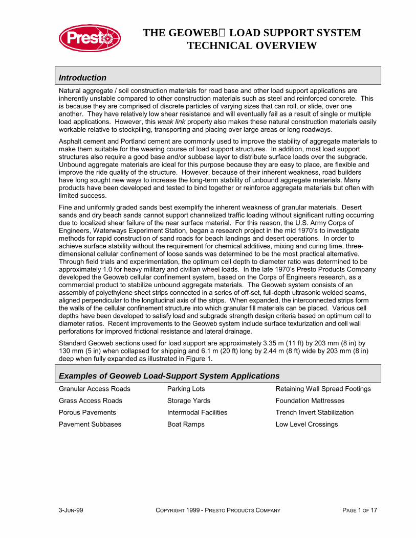
SURFACE
GEOWEB SECTION
INFILL
SUBBASE
GEOTEXTILE
SUBGRADE
UNCONFINED GRANULAR PAVEMENT SYSTEM
AGGREGATE BASE
SUBGRADE
SUBGRADE
AGGREGATE BASE
THE GEOWEB GRANULAR PAVEMENT SYSTEM

THE GEOWEB LOAD SUPPORT SYSTEMTECHNICAL OVERVIEW
ContentsIntroduction.................................................................................................................................................... 1
Examples of Geoweb Load-Support System Applications ............................................................................ 1
Figure 1 Standard Geoweb Sections................................................................................................. 2
Features and Benefits of the Geoweb Cellular Confinement System ........................................................... 2
Identifying Load Support Problems and Geoweb Solutions .......................................................................... 3
Soft Subgrades Problems.......................................................................................................................... 3
Surface Stability Problems......................................................................................................................... 3
Aesthetic / Environmental Problems.......................................................................................................... 3
Geoweb Load Support Systems - The Key Components.............................................................................. 4
Textured Geoweb system.......................................................................................................................... 4
Perforated Geoweb system ....................................................................................................................... 4
Infill materials............................................................................................................................................. 4
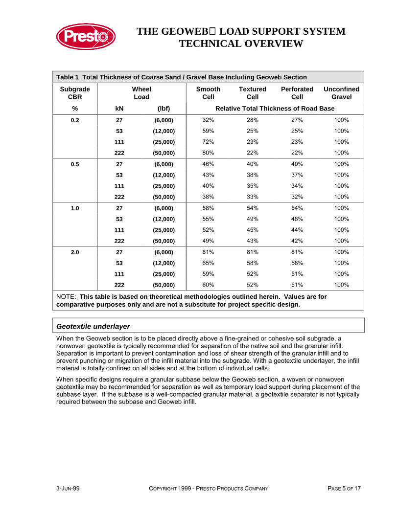
Table 1 Total Thickness of Coarse Sand / Gravel Base Including Geoweb Section ........................ 5
Geotextile underlayer................................................................................................................................. 5
Surface materials....................................................................................................................................... 6
Design Considerations and Methods ............................................................................................................ 6
Flexible Pavements ................................................................................................................................... 6
Figure 2 Flexible Pavement Detail..................................................................................................... 6
Granular Pavements.................................................................................................................................. 7
Figure 3 Granular Pavement Detail ................................................................................................... 7
Spread Footings ........................................................................................................................................ 7
Figure 4 Spread Footing Detail.......................................................................................................... 7
Design Parameters - Granular Pavements ................................................................................................... 7
Wheel Load................................................................................................................................................ 7
Tire Pressure ............................................................................................................................................. 8
Bearing Capacity Coefficient...................................................................................................................... 8
Depth to Top of Geoweb section ............................................................................................................... 8
Subgrade Strength..................................................................................................................................... 8
California Bearing Ratio (CBR) Test ...................................................................................................... 8
Table 2 Unit Loads for Standard Crushed Stone Material................................................................. 8
Standard Penetration Test ..................................................................................................................... 9
Shear Strength Tests ............................................................................................................................. 9
Angle of Internal Friction - Geoweb Infill Material ...................................................................................... 9
Figure 5 Angle of Internal Friction ..................................................................................................... 9
THE GEOWEB LOAD SUPPORT SYSTEMTECHNICAL OVERVIEW
Geoweb Cell Wall/Infill Friction Angle Ratio.............................................................................................10
Table 3 Recommended Peak Friction Angle Ratio..........................................................................10
Design Calculations Granular Pavements ...................................................................................................10
Variable Names........................................................................................................................................11
Calculations..............................................................................................................................................11
Table 4 Correlation of Subgrade Soil Strength Parameters for Cohesive (Fine-Grained) Soils ......12
Table 5 Total Thickness of Coarse Sand / Gravel Base Including Geoweb Section.......................13
Available Tools & Services ..........................................................................................................................15
General Overview.....................................................................................................................................15
Application Overview................................................................................................................................15
Case Histories..........................................................................................................................................15
SPECMaker™..........................................................................................................................................15
Design Package .......................................................................................................................................15
System Component Guideline..............................................................................................................15
Design Input Checklist..........................................................................................................................15
Material Specification ...........................................................................................................................15
CSI Format Specifications....................................................................................................................15
Construction Specifications ..................................................................................................................15
AutoCAD® Drawings .............................................................................................................................15
Technical Overview ..............................................................................................................................15
Construction Package ..............................................................................................................................15
Installation Guideline ............................................................................................................................15
Practical Tips & Suggestions................................................................................................................15
Videos ......................................................................................................................................................15
Solutions for an Unstable World CD ........................................................................................................15
Project Evaluation Service .......................................................................................................................15
Disclaimer ....................................................................................................................................................16
References ..................................................................................................................................................16
THE GEOWEB LOAD SUPPORT SYSTEMTECHNICAL OVERVIEW
3-JUN-99 COPYRIGHT 1999 - PRESTO PRODUCTS COMPANY PAGE 1 OF 17
IntroductionNatural aggregate / soil construction materials for road base and other load support applications areinherently unstable compared to other construction materials such as steel and reinforced concrete. Thisis because they are comprised of discrete particles of varying sizes that can roll, or slide, over oneanother. They have relatively low shear resistance and will eventually fail as a result of single or multipleload applications. However, this weak link property also makes these natural construction materials easilyworkable relative to stockpiling, transporting and placing over large areas or long roadways.
Asphalt cement and Portland cement are commonly used to improve the stability of aggregate materials tomake them suitable for the wearing course of load support structures. In addition, most load supportstructures also require a good base and/or subbase layer to distribute surface loads over the subgrade.Unbound aggregate materials are ideal for this purpose because they are easy to place, are flexible andimprove the ride quality of the structure. However, because of their inherent weakness, road buildershave long sought new ways to increase the long-term stability of unbound aggregate materials. Manyproducts have been developed and tested to bind together or reinforce aggregate materials but often withlimited success.
Fine and uniformly graded sands best exemplify the inherent weakness of granular materials. Desertsands and dry beach sands cannot support channelized traffic loading without significant rutting occurringdue to localized shear failure of the near surface material. For this reason, the U.S. Army Corps ofEngineers, Waterways Experiment Station, began a research project in the mid 1970’s to investigatemethods for rapid construction of sand roads for beach landings and desert operations. In order toachieve surface stability without the requirement for chemical additives, mixing and curing time, three-dimensional cellular confinement of loose sands was determined to be the most practical alternative.Through field trials and experimentation, the optimum cell depth to diameter ratio was determined to beapproximately 1.0 for heavy military and civilian wheel loads. In the late 1970’s Presto Products Companydeveloped the Geoweb cellular confinement system, based on the Corps of Engineers research, as acommercial product to stabilize unbound aggregate materials. The Geoweb system consists of anassembly of polyethylene sheet strips connected in a series of off-set, full-depth ultrasonic welded seams,aligned perpendicular to the longitudinal axis of the strips. When expanded, the interconnected strips formthe walls of the cellular confinement structure into which granular fill materials can be placed. Various celldepths have been developed to satisfy load and subgrade strength design criteria based on optimum cell todiameter ratios. Recent improvements to the Geoweb system include surface texturization and cell wallperforations for improved frictional resistance and lateral drainage.
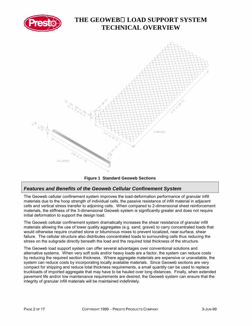
Standard Geoweb sections used for load support are approximately 3.35 m (11 ft) by 203 mm (8 in) by130 mm (5 in) when collapsed for shipping and 6.1 m (20 ft) long by 2.44 m (8 ft) wide by 203 mm (8 in)deep when fully expanded as illustrated in Figure 1.
Examples of Geoweb Load-Support System ApplicationsGranular Access Roads Parking Lots Retaining Wall Spread Footings
Grass Access Roads Storage Yards Foundation Mattresses
Porous Pavements Intermodal Facilities Trench Invert Stabilization
Pavement Subbases Boat Ramps Low Level Crossings
THE GEOWEB LOAD SUPPORT SYSTEMTECHNICAL OVERVIEW
PAGE 2 OF 17 COPYRIGHT 1999 - PRESTO PRODUCTS COMPANY 3-JUN-99
Figure 1 Standard Geoweb Sections
Features and Benefits of the Geoweb Cellular Confinement SystemThe Geoweb cellular confinement system improves the load-deformation performance of granular infillmaterials due to the hoop strength of individual cells, the passive resistance of infill material in adjacentcells and vertical stress transfer to adjoining cells. When compared to 2-dimensional sheet reinforcementmaterials, the stiffness of the 3-dimensional Geoweb system is significantly greater and does not requireinitial deformation to support the design load.
The Geoweb cellular confinement system dramatically increases the shear resistance of granular infillmaterials allowing the use of lower quality aggregates (e.g. sand, gravel) to carry concentrated loads thatwould otherwise require crushed stone or bituminous mixes to prevent localized, near-surface, shearfailure. The cellular structure also distributes concentrated loads to surrounding cells thus reducing thestress on the subgrade directly beneath the load and the required total thickness of the structure.
The Geoweb load support system can offer several advantages over conventional solutions andalternative systems. When very soft soils and/or heavy loads are a factor, the system can reduce costsby reducing the required section thickness. Where aggregate materials are expensive or unavailable, thesystem can reduce costs by incorporating locally available materials. Since Geoweb sections are verycompact for shipping and reduce total thickness requirements, a small quantity can be used to replacetruckloads of imported aggregate that may have to be hauled over long distances. Finally, when extendedpavement life and/or low maintenance requirements are desired, the Geoweb system can ensure that theintegrity of granular infill materials will be maintained indefinitely.
THE GEOWEB LOAD SUPPORT SYSTEMTECHNICAL OVERVIEW
3-JUN-99 COPYRIGHT 1999 - PRESTO PRODUCTS COMPANY PAGE 3 OF 17
Identifying Load Support Problems and Geoweb SolutionsLoad support design problems most commonly arise when:
• soft subgrade soils are encountered,
• surface soils are unstable, (i.e. good quality aggregates are locally unavailable or uneconomical) or,
• there are aesthetic and/or environmental consideration.
To identify load support problems where Geoweb cellular confinement should be considered, the followingquestions should be asked.
Soft Subgrades ProblemsAre there any constraints on undercutting or designing a thick structure? If yes, consider the Geowebcellular confinement system to reduce the section thickness.
Is it impossible to build a stable foundation mattress below the load structure because of a very soft,unstable subgrade condition? If yes, consider the Geoweb cellular confinement system, with a geotextileunderlayer, to bridge over the soft soil and support construction equipment while using a minimumthickness of cover material.
Conventional, non-Geoweb solutions to soft subgrades problems, may include:
• excavation of the soft soil and replacement with imported fill (usually granular),
• chemical stabilization of the subgrade soil, or
• design of a thick, multi-layered structure which may include high quality aggregate materials, asphalticconcrete and/or Portland cement concrete.
Thick pavement structures and/or deep excavation may not always be possible due to existing curbs andburied utilities in existing roads.
Surface Stability ProblemsDo the locally available soils (e.g. sands and gravels) have adequate shear strength to be used as awearing surface for a temporary or low-volume access road? If not, confinement of the local materials inthe Geoweb system should be weighed against the cost of importing higher quality aggregate materials.
Will aggregate degradation and lateral spreading of the pavement base course result in rutting andpremature failure of the pavement structure? If the subgrade is relatively competent, deformation andrutting of the base course is likely to be the cause of maintenance problems and reduce the potential lifeof the pavement structure. Using the Geoweb system to confine the base course will totally restrict lateralmovement that causes rutting and will minimize abrasion and wear on the aggregate infill material.
Few, if any, conventional solutions exist for this problem.
Aesthetic / Environmental ProblemsWould a grass surfaced, low volume access road for maintenance vehicles be more aesthetically pleasingthan a gravel or asphalt concrete surfaced pavement? If yes, the Geoweb cellular confinement systeminfilled with an aggregate/topsoil mix and vegetated is an attractive solution.
Is a porous pavement required for groundwater regeneration? If yes, the Geoweb cellular confinementsystem infilled with porous stone should definitely be considered. However, without confinement, porousaggregates are inherently unstable as surface materials.
THE GEOWEB LOAD SUPPORT SYSTEMTECHNICAL OVERVIEW
PAGE 4 OF 17 COPYRIGHT 1999 - PRESTO PRODUCTS COMPANY 3-JUN-99
Geoweb Load Support Systems - The Key Components
Textured Geoweb systemEngineered surface-textured polyethylene strips used in manufacturing Geoweb sections improve thefrictional interaction between the Geoweb cell walls and granular infill materials. The increase in cell-wall /infill-interface friction provides structural benefits in certain Geoweb applications.
In load support applications, the higher cell wall/infill interface friction increases the resistance to verticaldeformation of the infill soil relative to the cellular structure. Therefore, a more efficient transfer of verticalstress is provided to the surrounding cells. The result is a further reduction in vertical stress on the subgradecompared to a smooth walled geocell. For certain combinations of wheel loads and infill material properties,the surface texture makes it possible to further reduce the total required thickness of granular pavement oversmooth-walled geocells.
Results of small and large scale shear box tests on sand and stone materials with textured Geowebmaterials have demonstrated that Peak Coefficient Ratios (i.e. peak interface friction coefficient of texturedGeoweb sections divided by the peak interface friction coefficient of granular infill soil in-isolation) varied from0.63 (crushed stone materials) to 0.81 (coarse sand materials) compared to 0.64 (crushed stone materials)and 0.61 (coarse sand materials) with smooth Geoweb materials. Note that texturization does not increasethe interface friction with some crushed stone infills. The Peak Coefficient Ratio should not be confused withthe Peak Friction Angle Ratio defined in the section titled Geoweb Cell Wall/Infill Friction Angle Ratio.
Perforated Geoweb systemSimilar tests using sand and stone materials with the perforated Geoweb material demonstrated that theinterface frictional characteristics are similar, or in some cases better, than those with surface texturedGeoweb cells. Specifically, the Peak Coefficient Ratios of perforated Geoweb materials with crushed stoneand coarse sand infills were found to be 0.75 and 0.89 respectively.
The latter test results indicate that perforated cell walls can be as effective as textured cell walls in increasingthe interface friction. Therefore, the structural capacity of the perforated Geoweb load support system withcertain sand/gravel infills is more effective than the textured Geoweb system. Since perforations also offerthe advantage of lateral drainage, which is particularly useful over impermeable subgrades, the perforatedGeoweb system is the recommended choice for many pavement applications. Refer to Table 1 for anillustration of the significance of the performance advantage using textured and perforated cell wall type.
Infill materialsInfill materials for Geoweb load support applications should always be predominately granular with amaximum particle size of 50 mm (2 in). For best performance, the fines fraction (i.e. material passing the#200 sieve - 75 µm) should not be greater than 10%. Soils with greater than 10% fines have lowpermeability and lose strength dramatically when they become wet. Pure granular materials are notaffected by moisture fluctuations but are not as stable as granular materials with 5% - 10% fines. A smallfraction of fines will increase stability by reducing the voids ratio and binding the soil.
The Geoweb cellular confinement system is effective in increasing the stability of lower quality granularinfill materials such as poorly graded sands and gravels. With cellular confinement, poor quality granularinfills can be used as the surface or near-surface material of access roads where driving speeds arerelatively slow and ride quality is not a major concern. Higher quality aggregates are recommended forgranular surfaced pavements where traffic speeds are higher and a smoother riding surface is required.Good quality aggregates typically include well graded crushed stones or gravels with a maximum particlesize of 40 mm (1.5 in) and less than 8%, by weight, passing the #200 sieve. For long-term durability, thecoarse fraction of the aggregate should have a Los Angeles Abrasion test wear less than 50%. The finesfraction (i.e. passing the #200 sieve) should not be greater than two-thirds of the fraction passing the #40sieve and the fraction passing the #40 sieve should have a liquid limit no greater than 25%. The plasticityindex should be less than 6%.
THE GEOWEB LOAD SUPPORT SYSTEMTECHNICAL OVERVIEW
3-JUN-99 COPYRIGHT 1999 - PRESTO PRODUCTS COMPANY PAGE 5 OF 17
Table 1 Total Thickness of Coarse Sand / Gravel Base Including Geoweb Section
SubgradeCBR
WheelLoad
SmoothCell
TexturedCell
PerforatedCell
UnconfinedGravel
% kN (lbf) Relative Total Thickness of Road Base0.2 27 (6,000) 32% 28% 27% 100%
53 (12,000) 59% 25% 25% 100%
111 (25,000) 72% 23% 23% 100%
222 (50,000) 80% 22% 22% 100%
0.5 27 (6,000) 46% 40% 40% 100%
53 (12,000) 43% 38% 37% 100%
111 (25,000) 40% 35% 34% 100%
222 (50,000) 38% 33% 32% 100%
1.0 27 (6,000) 58% 54% 54% 100%
53 (12,000) 55% 49% 48% 100%
111 (25,000) 52% 45% 44% 100%
222 (50,000) 49% 43% 42% 100%
2.0 27 (6,000) 81% 81% 81% 100%
53 (12,000) 65% 58% 58% 100%
111 (25,000) 59% 52% 51% 100%
222 (50,000) 60% 52% 51% 100%
NOTE: This table is based on theoretical methodologies outlined herein. Values are forcomparative purposes only and are not a substitute for project specific design.
Geotextile underlayerWhen the Geoweb section is to be placed directly above a fine-grained or cohesive soil subgrade, anonwoven geotextile is typically recommended for separation of the native soil and the granular infill.Separation is important to prevent contamination and loss of shear strength of the granular infill and toprevent punching or migration of the infill material into the subgrade. With a geotextile underlayer, the infillmaterial is totally confined on all sides and at the bottom of individual cells.
When specific designs require a granular subbase below the Geoweb section, a woven or nonwovengeotextile may be recommended for separation as well as temporary load support during placement of thesubbase layer. If the subbase is a well-compacted granular material, a geotextile separator is not typicallyrequired between the subbase and Geoweb infill.
THE GEOWEB LOAD SUPPORT SYSTEMTECHNICAL OVERVIEW
PAGE 6 OF 17 COPYRIGHT 1999 - PRESTO PRODUCTS COMPANY 3-JUN-99
Surface materialsIn order to prevent trafficking directly on top of the Geoweb cell walls, it is generally recommended toplace a minimum 50 mm (2 in) of granular cover (i.e. overtopping) above the Geoweb cell walls. Thesurface material should be dense-graded crushed stone that is resistant to surface rutting. If trafficvolumes are high, a bituminous surface treatment can increase the stability of the riding surface.
If an asphalt concrete base or surface layer is to be placed over the infilled Geoweb base, the depth ofgranular cover above the cell walls should be at least 25 mm (1 in) to allow for minor consolidation of theinfill material and to insulate the polyethylene from direct contact with the hot mix asphalt concrete.
Design Considerations and MethodsThere is no single design method that encompasses the full range of Geoweb load support applications. Atheoretical design method, based on empirically derived design methods for unpaved roads over soft soils,has been developed for the Geoweb granular pavement system. Design methods for flexible pavements,spread footings, and granular pavements with unstable infill soils have yet to be developed. However, it wasthis latter function for which Geoweb was originally invented and developed and has proven effective,particularly with sand infill materials.
Recent results of large scale triaxial compression testing of the Geoweb cell infilled with granular materialsdemonstrate that the Geoweb system imparts an apparent cohesion of approximately 150 kPa (3000 psf) tothe confined material. This effective cohesion is in addition to the natural frictional shear strength of thegranular material. Presto is currently using this information to develop bearing-capacity design proceduresfor Geoweb load support structures that takes into account the additional shear strength provided by theapparent cohesion. These design procedures will apply to large spread footing and granular pavementapplications with poor-quality infill materials.
A discussion of currently available design procedures follows for Geoweb granular pavement systems andthe design approaches used for other Geoweb load support applications.
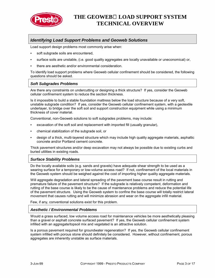
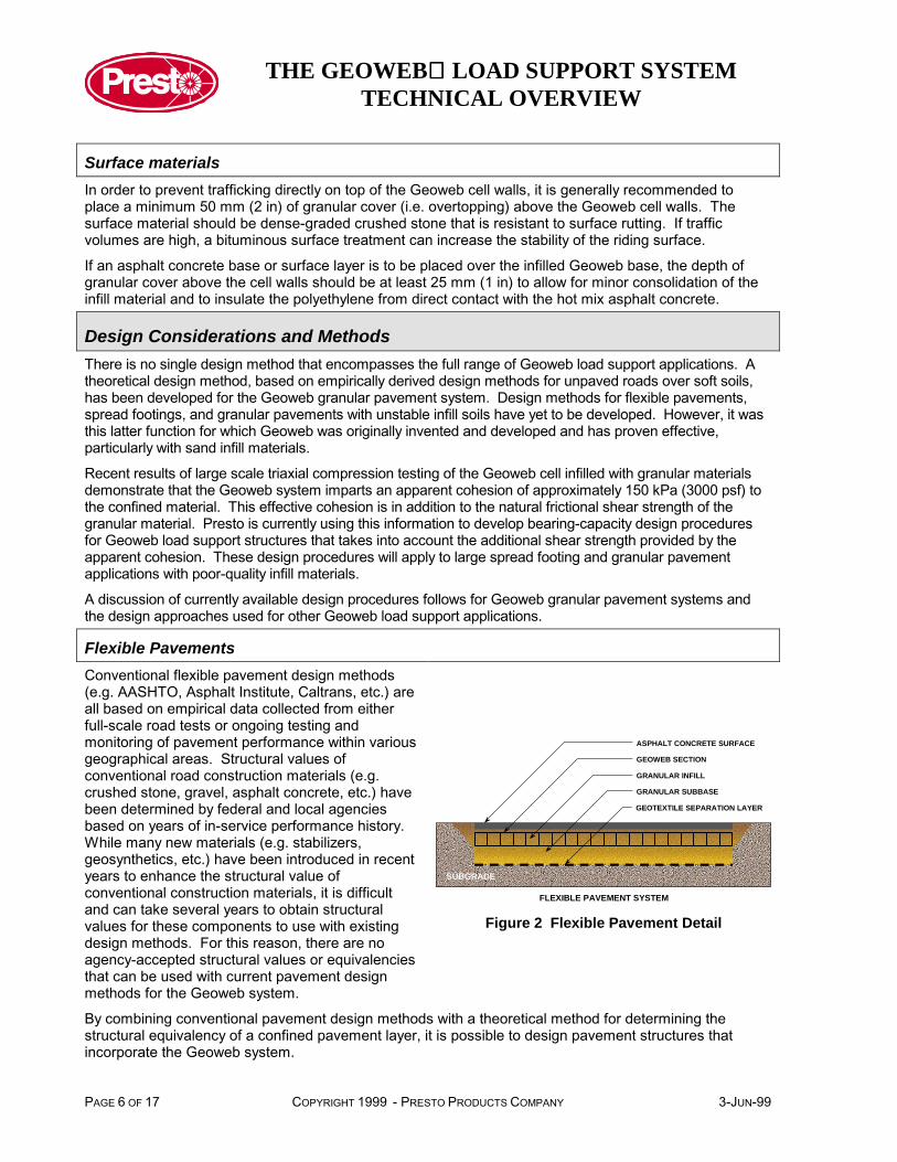
Flexible PavementsConventional flexible pavement design methods(e.g. AASHTO, Asphalt Institute, Caltrans, etc.) areall based on empirical data collected from eitherfull-scale road tests or ongoing testing andmonitoring of pavement performance within variousgeographical areas. Structural values ofconventional road construction materials (e.g.crushed stone, gravel, asphalt concrete, etc.) havebeen determined by federal and local agenciesbased on years of in-service performance history.While many new materials (e.g. stabilizers,geosynthetics, etc.) have been introduced in recentyears to enhance the structural value ofconventional construction materials, it is difficultand can take several years to obtain structuralvalues for these components to use with existingdesign methods. For this reason, there are noagency-accepted structural values or equivalenciesthat can be used with current pavement designmethods for the Geoweb system.
SUBGRADE
FLEXIBLE PAVEMENT SYSTEM
ASPHALT CONCRETE SURFACE
GEOWEB SECTION
GRANULAR INFILL
GRANULAR SUBBASE
GEOTEXTILE SEPARATION LAYER
Figure 2 Flexible Pavement Detail
By combining conventional pavement design methods with a theoretical method for determining thestructural equivalency of a confined pavement layer, it is possible to design pavement structures thatincorporate the Geoweb system.
THE GEOWEB LOAD SUPPORT SYSTEMTECHNICAL OVERVIEW
3-JUN-99 COPYRIGHT 1999 - PRESTO PRODUCTS COMPANY PAGE 7 OF 17
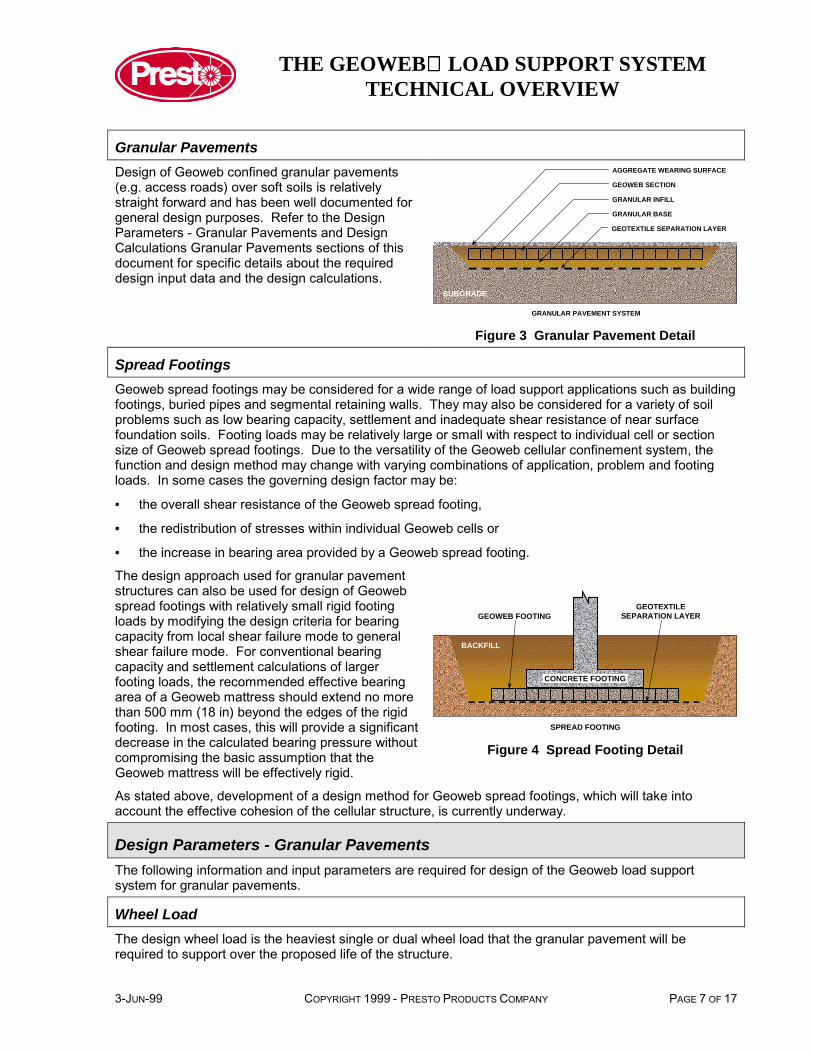
Granular PavementsDesign of Geoweb confined granular pavements(e.g. access roads) over soft soils is relativelystraight forward and has been well documented forgeneral design purposes. Refer to the DesignParameters - Granular Pavements and DesignCalculations Granular Pavements sections of thisdocument for specific details about the requireddesign input data and the design calculations.
SUBGRADE
GRANULAR PAVEMENT SYSTEM
AGGREGATE WEARING SURFACE
GEOWEB SECTION
GRANULAR INFILL
GRANULAR BASE
GEOTEXTILE SEPARATION LAYER
Figure 3 Granular Pavement Detail
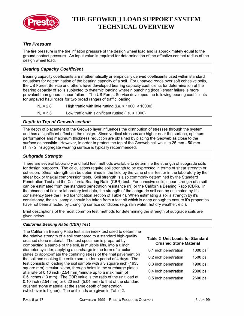
Spread FootingsGeoweb spread footings may be considered for a wide range of load support applications such as buildingfootings, buried pipes and segmental retaining walls. They may also be considered for a variety of soilproblems such as low bearing capacity, settlement and inadequate shear resistance of near surfacefoundation soils. Footing loads may be relatively large or small with respect to individual cell or sectionsize of Geoweb spread footings. Due to the versatility of the Geoweb cellular confinement system, thefunction and design method may change with varying combinations of application, problem and footingloads. In some cases the governing design factor may be:
• the overall shear resistance of the Geoweb spread footing,
• the redistribution of stresses within individual Geoweb cells or
• the increase in bearing area provided by a Geoweb spread footing.
The design approach used for granular pavementstructures can also be used for design of Geowebspread footings with relatively small rigid footingloads by modifying the design criteria for bearingcapacity from local shear failure mode to generalshear failure mode. For conventional bearingcapacity and settlement calculations of largerfooting loads, the recommended effective bearingarea of a Geoweb mattress should extend no morethan 500 mm (18 in) beyond the edges of the rigidfooting. In most cases, this will provide a significantdecrease in the calculated bearing pressure withoutcompromising the basic assumption that theGeoweb mattress will be effectively rigid.
SPREAD FOOTING
CONCRETE FOOTING
BACKFILL
GEOTEXTILESEPARATION LAYERGEOWEB FOOTING
Figure 4 Spread Footing Detail
As stated above, development of a design method for Geoweb spread footings, which will take intoaccount the effective cohesion of the cellular structure, is currently underway.
Design Parameters - Granular PavementsThe following information and input parameters are required for design of the Geoweb load supportsystem for granular pavements.
Wheel LoadThe design wheel load is the heaviest single or dual wheel load that the granular pavement will berequired to support over the proposed life of the structure.
THE GEOWEB LOAD SUPPORT SYSTEMTECHNICAL OVERVIEW
PAGE 8 OF 17 COPYRIGHT 1999 - PRESTO PRODUCTS COMPANY 3-JUN-99
Tire PressureThe tire pressure is the tire inflation pressure of the design wheel load and is approximately equal to theground contact pressure. An input value is required for determination of the effective contact radius of thedesign wheel load.
Bearing Capacity CoefficientBearing capacity coefficients are mathematically or empirically derived coefficients used within standardequations for determination of the bearing capacity of a soil. For unpaved roads over soft cohesive soils,the US Forest Service and others have developed bearing capacity coefficients for determination of thebearing capacity of soils subjected to dynamic loading wherein punching (local) shear failure is moreprevalent than general shear failure. The US Forest Service developed the following bearing coefficientsfor unpaved haul roads for two broad ranges of traffic loading.
Nc = 2.8 High traffic with little rutting (i.e. > 1000, < 10000)
Nc = 3.3 Low traffic with significant rutting (i.e. < 1000)
Depth to Top of Geoweb sectionThe depth of placement of the Geoweb layer influences the distribution of stresses through the systemand has a significant effect on the design. Since vertical stresses are higher near the surface, optimumperformance and maximum thickness reduction are obtained by placing the Geoweb as close to thesurface as possible. However, in order to protect the top of the Geoweb cell walls, a 25 mm - 50 mm(1 in - 2 in) aggregate wearing surface is typically recommended.
Subgrade StrengthThere are several laboratory and field test methods available to determine the strength of subgrade soilsfor design purposes. The calculations require soil strength to be expressed in terms of shear strength orcohesion. Shear strength can be determined in the field by the vane shear test or in the laboratory by theshear box or triaxial compression tests. Soil strength is also commonly determined by the StandardPenetration Test and the California Bearing Ratio (CBR) test. For cohesive soils, shear strength of a soilcan be estimated from the standard penetration resistance (N) or the California Bearing Ratio (CBR). Inthe absence of field or laboratory test data, the strength of the subgrade soil can be estimated by it’sconsistency (see the Field Identification section of Table 4). When estimating a soil’s strength by it’sconsistency, the soil sample should be taken from a test pit which is deep enough to ensure it’s propertieshave not been affected by changing surface conditions (e.g. rain water, hot dry weather, etc.).
Brief descriptions of the most common test methods for determining the strength of subgrade soils aregiven below.
California Bearing Ratio (CBR) Test
Table 2 Unit Loads for StandardCrushed Stone Material
0.1 inch penetration 1000 psi
0.2 inch penetration 1500 psi
0.3 inch penetration 1900 psi
0.4 inch penetration 2300 psi
The California Bearing Ratio test is an index test used to determinethe relative strength of a soil compared to a standard high-qualitycrushed stone material. The test specimen is prepared bycompacting a sample of the soil, in multiple lifts, into a 6 inchdiameter cylinder, applying a surcharge in the form of circularplates to approximate the confining stress of the final pavement onthe soil and soaking the entire sample for a period of 4 days. Thetest consists of loading the soil sample with a 3 square inch (1935square mm) circular piston, through holes in the surcharge plates,at a rate of 0.10 inch (2.54 mm)/minute up to a maximum of0.5 inches (13 mm). The CBR value is the ratio of the unit load at0.10 inch (2.54 mm) or 0.20 inch (5.04 mm) to that of the standardcrushed stone material at the same depth of penetration(whichever is higher). The unit loads are given in Table 2.
0.5 inch penetration 2600 psi
THE GEOWEB LOAD SUPPORT SYSTEMTECHNICAL OVERVIEW
3-JUN-99 COPYRIGHT 1999 - PRESTO PRODUCTS COMPANY PAGE 9 OF 17
Standard Penetration Test
The standard penetration test provides an indication of the density, and the angle of internal friction ofcohesionless soils and the shear strength of cohesive soils. The tests consists of driving a split spoonsampler, equipped with a cutting shoe and attached to the end of a drill rod, into a soil by dropping a140 lb (63.6 kg) hammer a distance of 30 inches (0.76 m). A split spoon sampler is a thick-walled steeltube, split lengthwise, used to obtain undisturbed samples of soil from drill holes. The number of blowsrequired for each 6 inches (150 mm) of penetration of the split spoon sampler is recorded. The standardpenetration resistance is the sum of the blows for the second and third increments of 6 inches (150 mm)and is termed N in blows/ft (blows/300 mm).
Shear Strength Tests
The shear strength of a soil is the stress at which the soil fails in shear. It can be calculated by dividingthe shear force at which a soil fails by the cross-sectional area of shear or, if the cohesion and angle ofinternal friction are known, by the general Coulomb equation.
s = c + σ tan φ
where c is the soil’s cohesion (i.e. interparticle attraction) expressed in terms of force per unit area
σ is the overburden or surcharge pressure in terms of force per unit area
φ is the soil’s angle of internal friction (i.e. resistance to interparticle slip) in degrees
Granular soils do not have cohesion and therefore shear strength is governed by overburden pressurethat explains why granular pavement surface materials are inherently unstable. Undrained cohesive soils(e.g. soft and saturated clays) do not have internal friction and therefore shear strength is governed bycohesion that can vary with moisture content. Drained cohesive soils can have both cohesion and internalfriction.
The shear strength of granular soils can be measured in a laboratory by the shear box test. Cohesion andthe angle of internal friction of cohesive soils can be measured in a laboratory for drained and undrainedconditions by triaxial compression tests. In the field, shear strength can be measured by the field vaneshear test. Refer to a textbook on soil mechanics or geotechnical engineering for more information aboutthe shear strength of soils and test methods.
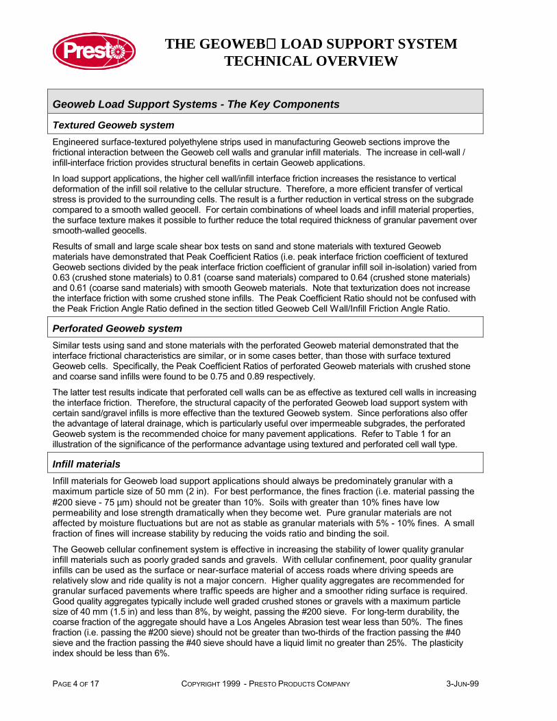
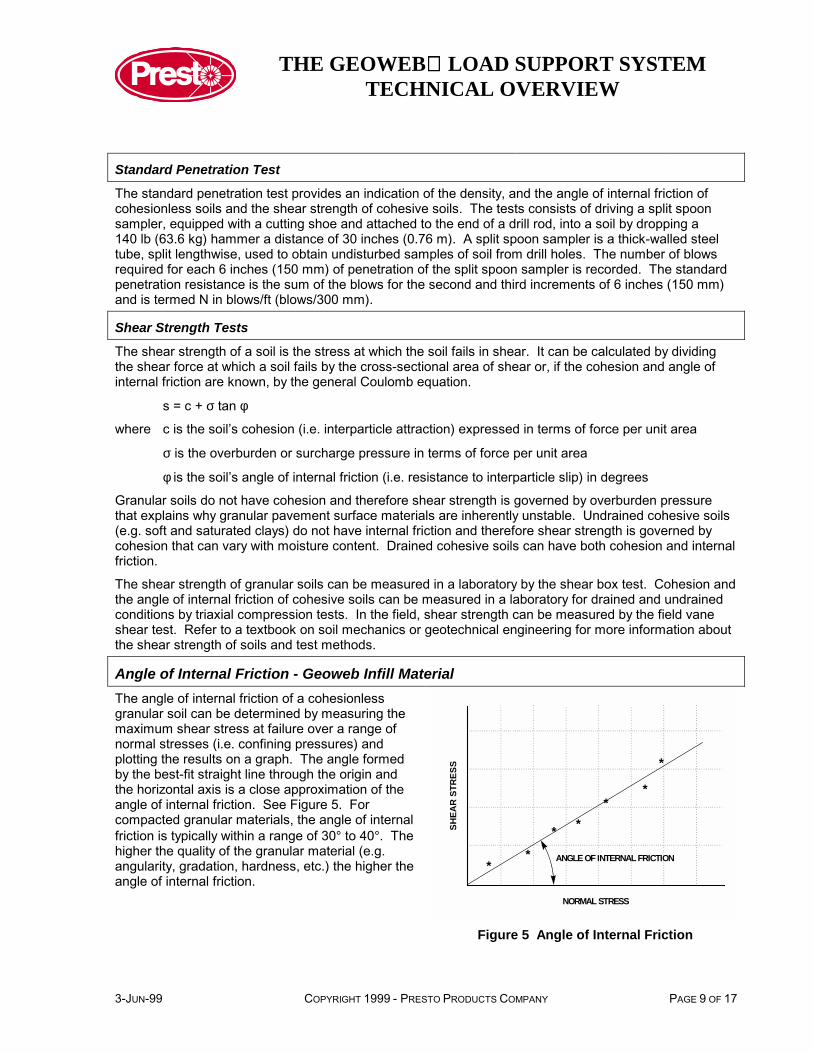
Angle of Internal Friction - Geoweb Infill MaterialThe angle of internal friction of a cohesionlessgranular soil can be determined by measuring themaximum shear stress at failure over a range ofnormal stresses (i.e. confining pressures) andplotting the results on a graph. The angle formedby the best-fit straight line through the origin andthe horizontal axis is a close approximation of theangle of internal friction. See Figure 5. Forcompacted granular materials, the angle of internalfriction is typically within a range of 30° to 40°. Thehigher the quality of the granular material (e.g.angularity, gradation, hardness, etc.) the higher theangle of internal friction.
NORMAL STRESS
SHEA
R S
TRES
S
**
* **
*
*
ANGLE OF INTERNAL FRICTION
Figure 5 Angle of Internal Friction
THE GEOWEB LOAD SUPPORT SYSTEMTECHNICAL OVERVIEW
PAGE 10 OF 17 COPYRIGHT 1999 - PRESTO PRODUCTS COMPANY 3-JUN-99
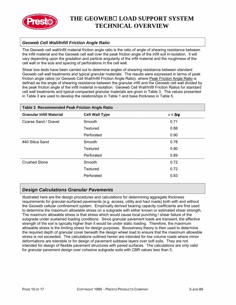
Geoweb Cell Wall/Infill Friction Angle RatioThe Geoweb cell wall/infill material friction angle ratio is the ratio of angle of shearing resistance betweenthe infill material and the Geoweb cell wall over the peak friction angle of the infill soil in-isolation. It willvary depending upon the gradation and particle angularity of the infill material and the roughness of thecell wall or the size and spacing of perforations in the cell wall.
Shear box tests have been carried out to determine angles of shearing resistance between standardGeoweb cell wall treatments and typical granular materials. The results were expressed in terms of peakfriction angle ratios (or Geoweb Cell Wall/Infill Friction Angle Ratio), where Peak Friction Angle Ratio isdefined as the angle of shearing resistance between the granular infill and the Geoweb cell wall divided bythe peak friction angle of the infill material in-isolation. Geoweb Cell Wall/Infill Friction Ratios for standardcell wall treatments and typical compacted granular materials are given in Table 3. The values presentedin Table 3 are used to develop the relationships in Table 1 and base thickness in Table 5.
Table 3 Recommended Peak Friction Angle Ratio
Granular Infill Material Cell Wall Type r = δδδδ/φφφφ
Coarse Sand / Gravel Smooth 0.71
Textured 0.88
Perforated 0.90
#40 Silica Sand Smooth 0.78
Textured 0.90
Perforated 0.89
Crushed Stone Smooth 0.72
Textured 0.72
Perforated 0.83
Design Calculations Granular PavementsIllustrated here are the design procedures and calculations for determining aggregate thicknessrequirements for granular-surfaced pavements (e.g. access, utility and haul roads) both with and withoutthe Geoweb cellular confinement system. Empirically derived bearing capacity coefficients are first usedto determine the maximum allowable stress on a subgrade with either known or estimated shear strength.The maximum allowable stress is that stress which would cause local punching / shear failure of thesubgrade under sustained loading conditions. Since granular pavement loads are transient, the effectivestrength of the soil is typically higher than it would be under static loading. Therefore, the maximumallowable stress is the limiting stress for design purposes. Boussinesq theory is then used to determinethe required depth of granular cover beneath the design wheel load to ensure that the maximum allowablestress is not exceeded. The calculations outlined herein are intended for low volume roads where minordeformations are tolerable or for design of pavement subbase layers over soft soils. They are notintended for design of flexible pavement structures with paved surfaces. The calculations are only validfor granular pavement design over cohesive subgrade soils with CBR values less than 5.
THE GEOWEB LOAD SUPPORT SYSTEMTECHNICAL OVERVIEW
3-JUN-99 COPYRIGHT 1999 - PRESTO PRODUCTS COMPANY PAGE 11 OF 17
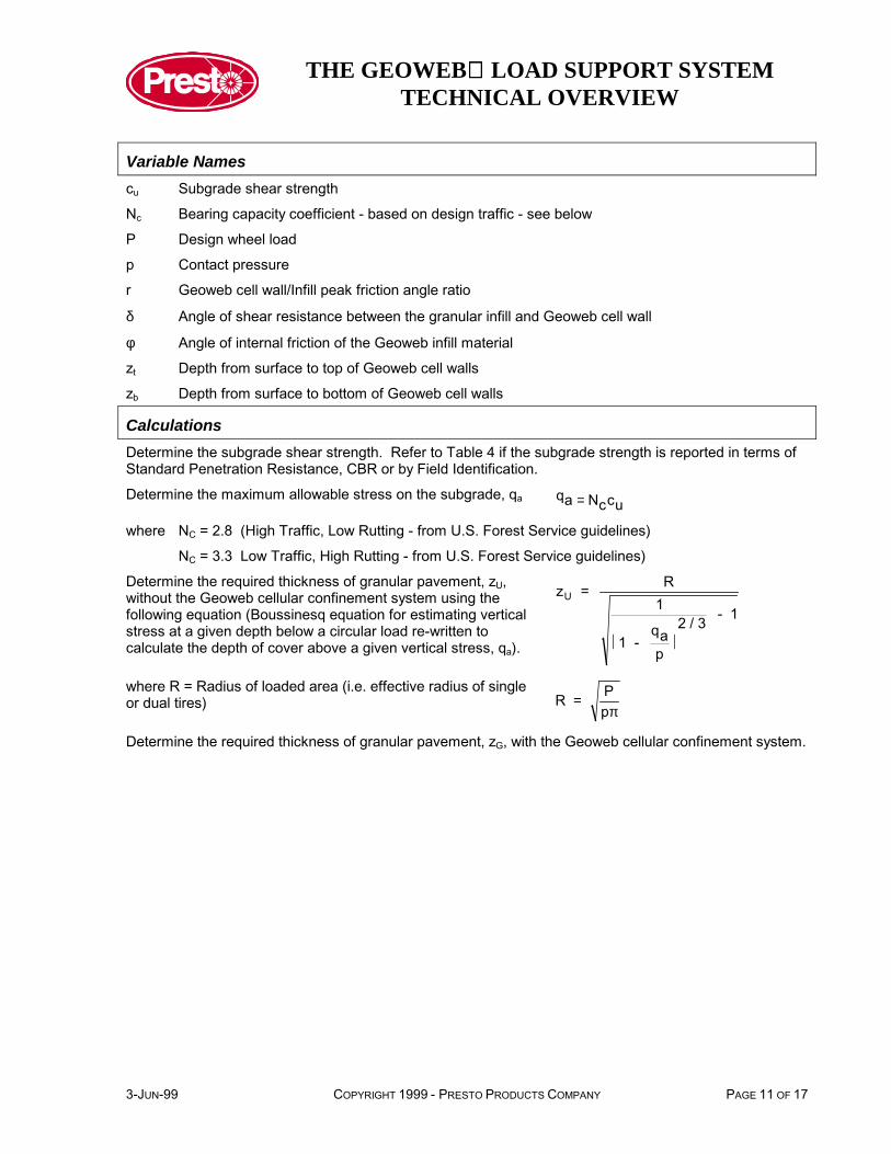
Variable Namescu Subgrade shear strength
Nc Bearing capacity coefficient - based on design traffic - see below
P Design wheel load
p Contact pressure
r Geoweb cell wall/Infill peak friction angle ratio
δ Angle of shear resistance between the granular infill and Geoweb cell wall
φ Angle of internal friction of the Geoweb infill material
zt Depth from surface to top of Geoweb cell walls
zb Depth from surface to bottom of Geoweb cell walls
CalculationsDetermine the subgrade shear strength. Refer to Table 4 if the subgrade strength is reported in terms ofStandard Penetration Resistance, CBR or by Field Identification.
Determine the maximum allowable stress on the subgrade, qa qa Nccu=
where NC = 2.8 (High Traffic, Low Rutting - from U.S. Forest Service guidelines)
NC = 3.3 Low Traffic, High Rutting - from U.S. Forest Service guidelines)
Determine the required thickness of granular pavement, zU,without the Geoweb cellular confinement system using thefollowing equation (Boussinesq equation for estimating verticalstress at a given depth below a circular load re-written tocalculate the depth of cover above a given vertical stress, qa).
z = R1
2 / 31 - aq
p
- 1U
� �
where R = Radius of loaded area (i.e. effective radius of singleor dual tires) R = P
pπ
Determine the required thickness of granular pavement, zG, with the Geoweb cellular confinement system.

THE GEOWEB LOAD SUPPORT SYSTEMTECHNICAL OVERVIEW
PAGE 12 OF 17 COPYRIGHT 1999 - PRESTO PRODUCTS COMPANY 3-JUN-99
Table 4 Correlation of Subgrade Soil Strength Parameters for Cohesive (Fine-Grained) Soils
CaliforniaBearing Ratio
UndrainedShear Strength
StandardPenetrationResistance
Field Identification
CBR (%) cu kPa (psi) SPT (blows/ft)
< 0.4 < 11.7(1.7)
< 2 Very soft (extruded between fingers whensqueezed)
0.4 - 0.8 11.7 - 24.1(1.7) - (3.5)
2 - 4 Soft (molded by light finger pressure)
0.8 - 1.6 24.1 - 47.6(3.5) - (6.9)
4 - 8 Medium (molded by strong finger pressure)
1.6 - 3.2 47.6 - 95.8(6.9) - (13.9)
8 - 15 Stiff (readily indented by thumb but penetratedwith great effort)
3.2 - 6.4 95.8 - 191(13.9) - (27.7)
15 - 30 Very stiff (readily indented by thumbnail)
> 6.4 > 191(27.7)
> 30 Hard (indented with difficulty by thumbnail)
The total required thickness of granular pavement with the Geoweb cellular confinement system is afunction of the Geoweb cell depth, the depth of placement below the applied load, the wheel load and tirepressure and the infill material properties. Surface stress (i.e. wheel load contact pressure) is distributedboth vertically and horizontally through the Geoweb cellular structure. Horizontal stresses, in turn, areconverted into vertical resisting stresses along the cell walls thus reducing the total vertical stress directlybeneath the center of the loaded area. The total resisting stress provided by the Geoweb cell structure iscalculated and added to the maximum allowable stress on the subgrade for determination of the totalrequired thickness of granular pavement with the Geoweb cellular confinement system.
The first step is to select the Geoweb section placement depth, zt within the granular pavement structure.Since vertical stresses are higher near the surface, optimum performance and maximum thicknessreduction are obtained by placing the Geoweb as close to the surface as possible. However, to protect thetop of the Geoweb cell walls, a 25 mm to 50 mm (1 in to 2 in) aggregate wearing surface is typicallyrecommended.
After selecting a trial depth of placement, calculate the verticalstress, σvt, at the top of the Geoweb section using the followingequation.
σ vt p 1 1
1 Rz
2
32
t
= −
+ � �
�
�
������
�������
�
�
�������
Next, calculate the vertical stress, σvb, at the bottom of theGeoweb section. The bottom depth, zb, is the top depth, zt, plusthe thickness (or depth) of the Geoweb section.
σ vb p 1 1
1 Rz
2
32
b
= −
+ � �
�
�
������
�������
�
�
�������
THE GEOWEB LOAD SUPPORT SYSTEMTECHNICAL OVERVIEW
3-JUN-99 COPYRIGHT 1999 - PRESTO PRODUCTS COMPANY PAGE 13 OF 17
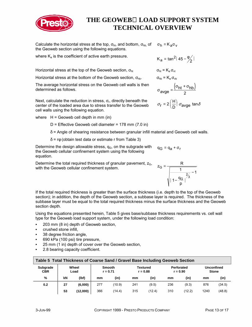
Calculate the horizontal stress at the top, σht, and bottom, σhb, ofthe Geoweb section using the following equations.
σ σh a vK=
where Ka is the coefficient of active earth pressure. Ka = −� �tan2 45 2φ
Horizontal stress at the top of the Geoweb section, σht σht = Ka σvt
Horizontal stress at the bottom of the Geoweb section, σhb. σhb = Ka σvb
The average horizontal stress on the Geoweb cell walls is thendetermined as follows. ( )
σσ σ
avgeht hb
2=
+
Next, calculate the reduction in stress, σr, directly beneath thecenter of the loaded area due to stress transfer to the Geowebcell walls using the following equation.
σ σ δr 2 HD avge tan= �
��
��
where H = Geoweb cell depth in mm (in)
D = Effective Geoweb cell diameter = 178 mm (7.0 in)
δ = Angle of shearing resistance between granular infill material and Geoweb cell walls.
δ = rφ (obtain test data or estimate r from Table 3)
Determine the design allowable stress, qG, on the subgrade withthe Geoweb cellular confinement system using the followingequation.
q qG a r= + σ
Determine the total required thickness of granular pavement, zG,with the Geoweb cellular confinement system. z R
1
1 qp
1G
G2
3
=
−� �
−
If the total required thickness is greater than the surface thickness (i.e. depth to the top of the Geowebsection); in addition, the depth of the Geoweb section, a subbase layer is required. The thickness of thesubbase layer must be equal to the total required thickness minus the surface thickness and the Geowebsection depth.
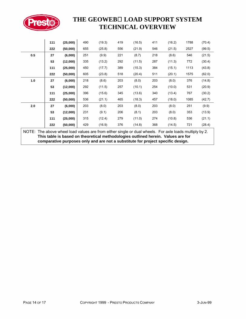
Using the equations presented herein, Table 5 gives base/subbase thickness requirements vs. cell walltype for the Geoweb load support system, under the following load condition:• 203 mm (8 in) depth of Geoweb section,• crushed stone infill,• 38 degree friction angle,• 690 kPa (100 psi) tire pressure,• 25 mm (1 in) depth of cover over the Geoweb section,• 2.8 bearing capacity coefficient.
Table 5 Total Thickness of Coarse Sand / Gravel Base Including Geoweb SectionSubgrade
CBRWheelLoad
Smoothr = 0.71
Texturedr = 0.88
Perforatedr = 0.90
UnconfinedStone
% kN (lbf) mm (in) mm (in) mm (in) mm (in)
0.2 27 (6,000) 277 (10.9) 241 (9.5) 236 (9.3) 876 (34.5)
53 (12,000) 366 (14.4) 315 (12.4) 310 (12.2) 1240 (48.8)
THE GEOWEB LOAD SUPPORT SYSTEMTECHNICAL OVERVIEW
PAGE 14 OF 17 COPYRIGHT 1999 - PRESTO PRODUCTS COMPANY 3-JUN-99
111 (25,000) 490 (19.3) 419 (16.5) 411 (16.2) 1788 (70.4)
222 (50,000) 655 (25.8) 556 (21.9) 546 (21.5) 2527 (99.5)
0.5 27 (6,000) 251 (9.9) 221 (8.7) 218 (8.6) 546 (21.5)
53 (12,000) 335 (13.2) 292 (11.5) 287 (11.3) 772 (30.4)
111 (25,000) 450 (17.7) 389 (15.3) 384 (15.1) 1113 (43.8)
222 (50,000) 605 (23.8) 518 (20.4) 511 (20.1) 1575 (62.0)
1.0 27 (6,000) 218 (8.6) 203 (8.0) 203 (8.0) 376 (14.8)
53 (12,000) 292 (11.5) 257 (10.1) 254 (10.0) 531 (20.9)
111 (25,000) 396 (15.6) 345 (13.6) 340 (13.4) 767 (30.2)
222 (50,000) 536 (21.1) 465 (18.3) 457 (18.0) 1085 (42.7)
2.0 27 (6,000) 203 (8.0) 203 (8.0) 203 (8.0) 251 (9.9)
53 (12,000) 231 (9.1) 206 (8.1) 203 (8.0) 353 (13.9)
111 (25,000) 315 (12.4) 279 (11.0) 274 (10.8) 536 (21.1)
222 (50,000) 429 (16.9) 376 (14.8) 368 (14.5) 721 (28.4)
NOTE: The above wheel load values are from either single or dual wheels. For axle loads multiply by 2.This table is based on theoretical methodologies outlined herein. Values are forcomparative purposes only and are not a substitute for project specific design.
THE GEOWEB LOAD SUPPORT SYSTEMTECHNICAL OVERVIEW
3-JUN-99 COPYRIGHT 1999 - PRESTO PRODUCTS COMPANY PAGE 15 OF 17
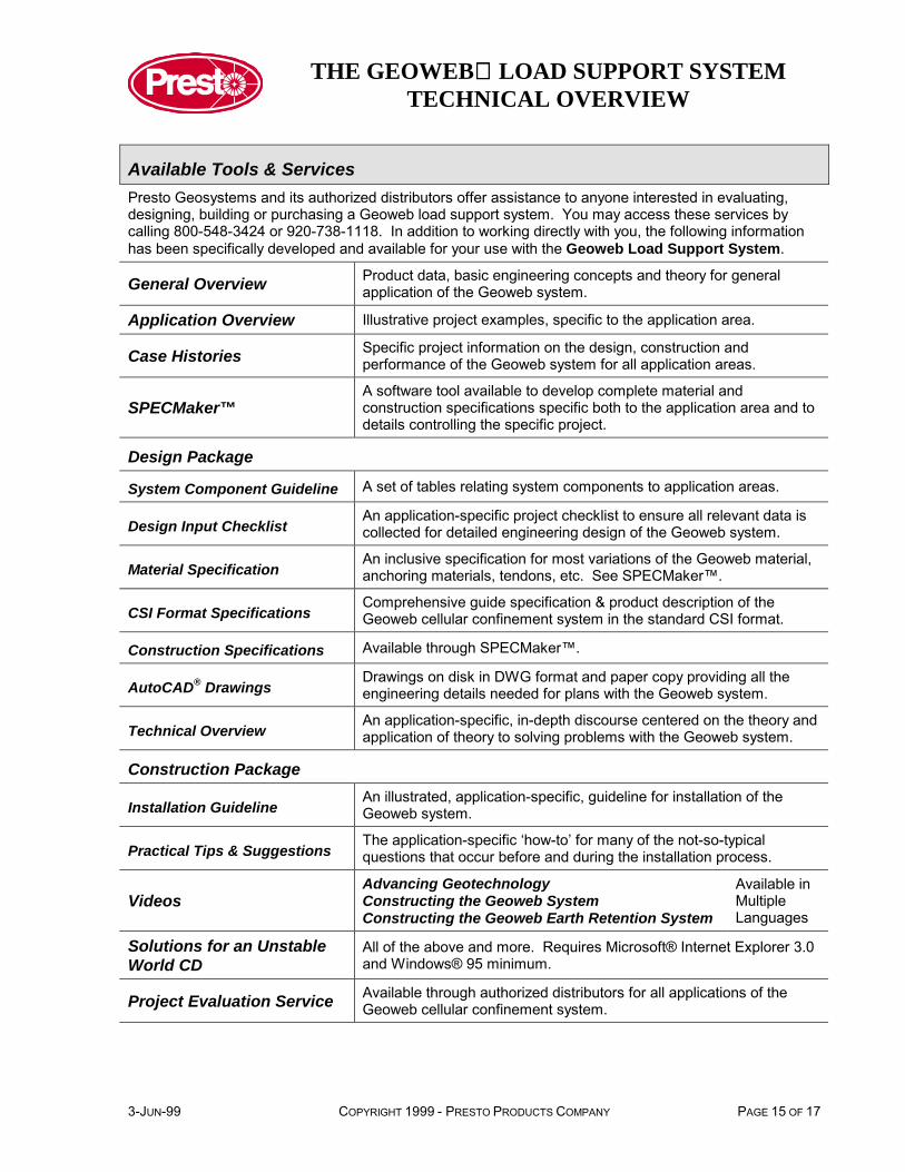
Available Tools & ServicesPresto Geosystems and its authorized distributors offer assistance to anyone interested in evaluating,designing, building or purchasing a Geoweb load support system. You may access these services bycalling 800-548-3424 or 920-738-1118. In addition to working directly with you, the following informationhas been specifically developed and available for your use with the Geoweb Load Support System.
General Overview Product data, basic engineering concepts and theory for generalapplication of the Geoweb system.
Application Overview Illustrative project examples, specific to the application area.
Case Histories Specific project information on the design, construction andperformance of the Geoweb system for all application areas.
SPECMaker™A software tool available to develop complete material andconstruction specifications specific both to the application area and todetails controlling the specific project.
Design Package
System Component Guideline A set of tables relating system components to application areas.
Design Input ChecklistAn application-specific project checklist to ensure all relevant data iscollected for detailed engineering design of the Geoweb system.
Material SpecificationAn inclusive specification for most variations of the Geoweb material,anchoring materials, tendons, etc. See SPECMaker™.
CSI Format SpecificationsComprehensive guide specification & product description of theGeoweb cellular confinement system in the standard CSI format.
Construction Specifications Available through SPECMaker™.
AutoCAD® DrawingsDrawings on disk in DWG format and paper copy providing all theengineering details needed for plans with the Geoweb system.
Technical OverviewAn application-specific, in-depth discourse centered on the theory andapplication of theory to solving problems with the Geoweb system.
Construction Package
Installation GuidelineAn illustrated, application-specific, guideline for installation of theGeoweb system.
Practical Tips & SuggestionsThe application-specific ‘how-to’ for many of the not-so-typicalquestions that occur before and during the installation process.
VideosAdvancing GeotechnologyConstructing the Geoweb SystemConstructing the Geoweb Earth Retention System
Available inMultipleLanguages
Solutions for an UnstableWorld CD
All of the above and more. Requires Microsoft® Internet Explorer 3.0and Windows® 95 minimum.
Project Evaluation Service Available through authorized distributors for all applications of theGeoweb cellular confinement system.
THE GEOWEB LOAD SUPPORT SYSTEMTECHNICAL OVERVIEW
PAGE 16 OF 17 COPYRIGHT 1999 - PRESTO PRODUCTS COMPANY 3-JUN-99
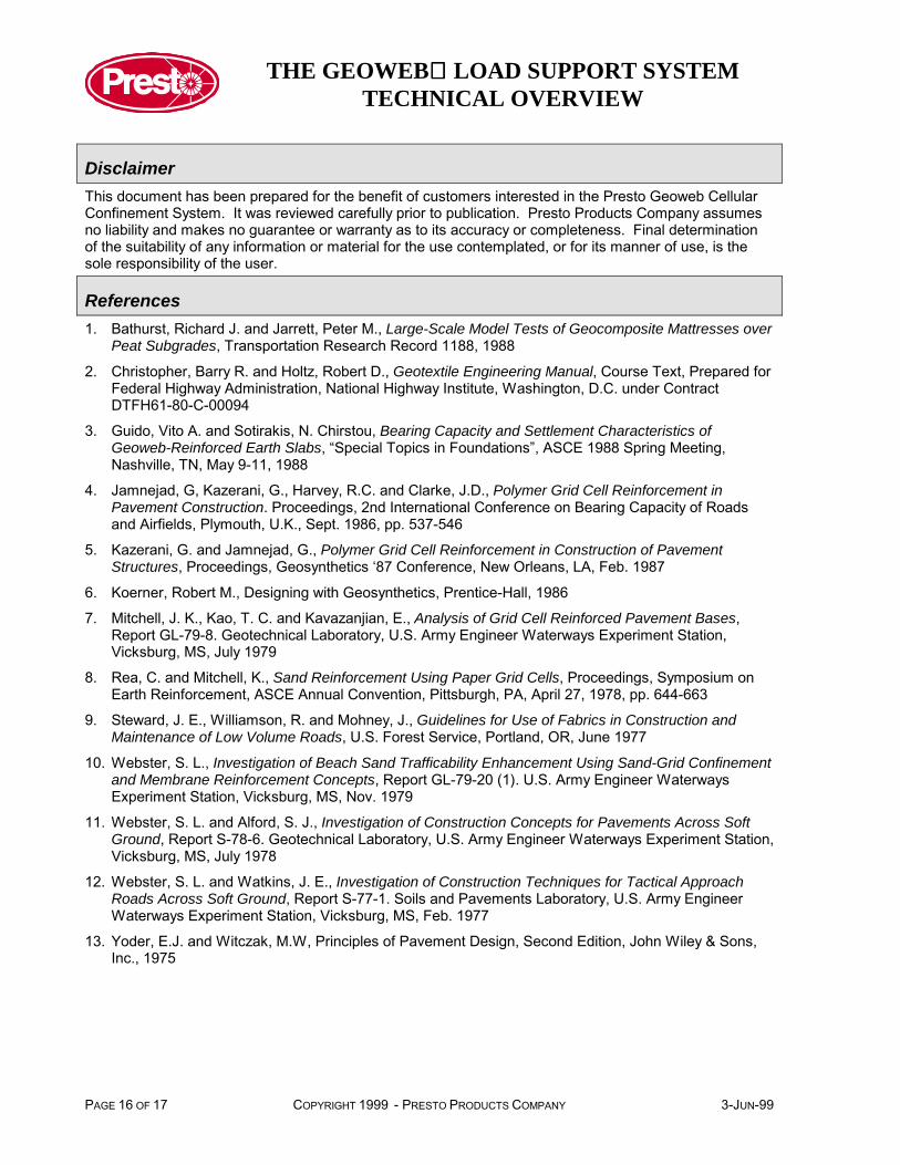
DisclaimerThis document has been prepared for the benefit of customers interested in the Presto Geoweb CellularConfinement System. It was reviewed carefully prior to publication. Presto Products Company assumesno liability and makes no guarantee or warranty as to its accuracy or completeness. Final determinationof the suitability of any information or material for the use contemplated, or for its manner of use, is thesole responsibility of the user.
References1. Bathurst, Richard J. and Jarrett, Peter M., Large-Scale Model Tests of Geocomposite Mattresses over
Peat Subgrades, Transportation Research Record 1188, 1988
2. Christopher, Barry R. and Holtz, Robert D., Geotextile Engineering Manual, Course Text, Prepared forFederal Highway Administration, National Highway Institute, Washington, D.C. under ContractDTFH61-80-C-00094
3. Guido, Vito A. and Sotirakis, N. Chirstou, Bearing Capacity and Settlement Characteristics ofGeoweb-Reinforced Earth Slabs, “Special Topics in Foundations”, ASCE 1988 Spring Meeting,Nashville, TN, May 9-11, 1988
4. Jamnejad, G, Kazerani, G., Harvey, R.C. and Clarke, J.D., Polymer Grid Cell Reinforcement inPavement Construction. Proceedings, 2nd International Conference on Bearing Capacity of Roadsand Airfields, Plymouth, U.K., Sept. 1986, pp. 537-546
5. Kazerani, G. and Jamnejad, G., Polymer Grid Cell Reinforcement in Construction of PavementStructures, Proceedings, Geosynthetics ‘87 Conference, New Orleans, LA, Feb. 1987
6. Koerner, Robert M., Designing with Geosynthetics, Prentice-Hall, 1986
7. Mitchell, J. K., Kao, T. C. and Kavazanjian, E., Analysis of Grid Cell Reinforced Pavement Bases,Report GL-79-8. Geotechnical Laboratory, U.S. Army Engineer Waterways Experiment Station,Vicksburg, MS, July 1979
8. Rea, C. and Mitchell, K., Sand Reinforcement Using Paper Grid Cells, Proceedings, Symposium onEarth Reinforcement, ASCE Annual Convention, Pittsburgh, PA, April 27, 1978, pp. 644-663
9. Steward, J. E., Williamson, R. and Mohney, J., Guidelines for Use of Fabrics in Construction andMaintenance of Low Volume Roads, U.S. Forest Service, Portland, OR, June 1977
10. Webster, S. L., Investigation of Beach Sand Trafficability Enhancement Using Sand-Grid Confinementand Membrane Reinforcement Concepts, Report GL-79-20 (1). U.S. Army Engineer WaterwaysExperiment Station, Vicksburg, MS, Nov. 1979
11. Webster, S. L. and Alford, S. J., Investigation of Construction Concepts for Pavements Across SoftGround, Report S-78-6. Geotechnical Laboratory, U.S. Army Engineer Waterways Experiment Station,Vicksburg, MS, July 1978
12. Webster, S. L. and Watkins, J. E., Investigation of Construction Techniques for Tactical ApproachRoads Across Soft Ground, Report S-77-1. Soils and Pavements Laboratory, U.S. Army EngineerWaterways Experiment Station, Vicksburg, MS, Feb. 1977
13. Yoder, E.J. and Witczak, M.W, Principles of Pavement Design, Second Edition, John Wiley & Sons,Inc., 1975