Embed Size (px)
Citation preview
Surface Manipulation Using a Paper Sculpture Metaphor
Glenn McCordDept. of Computer Science
University of AucklandAuckland, New Zealand
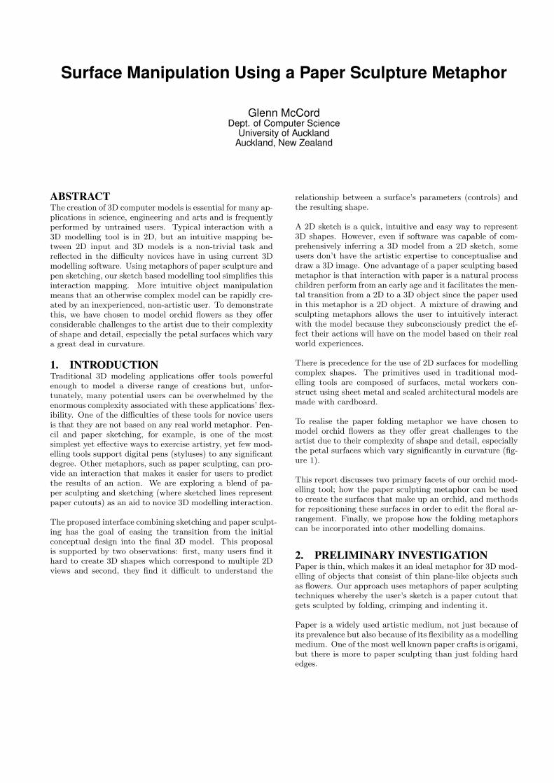
ABSTRACTThe creation of 3D computer models is essential for many ap-plications in science, engineering and arts and is frequentlyperformed by untrained users. Typical interaction with a3D modelling tool is in 2D, but an intuitive mapping be-tween 2D input and 3D models is a non-trivial task andreflected in the difficulty novices have in using current 3Dmodelling software. Using metaphors of paper sculpture andpen sketching, our sketch based modelling tool simplifies thisinteraction mapping. More intuitive object manipulationmeans that an otherwise complex model can be rapidly cre-ated by an inexperienced, non-artistic user. To demonstratethis, we have chosen to model orchid flowers as they offerconsiderable challenges to the artist due to their complexityof shape and detail, especially the petal surfaces which varya great deal in curvature.
1. INTRODUCTIONTraditional 3D modeling applications offer tools powerfulenough to model a diverse range of creations but, unfor-tunately, many potential users can be overwhelmed by theenormous complexity associated with these applications’ flex-ibility. One of the difficulties of these tools for novice usersis that they are not based on any real world metaphor. Pen-cil and paper sketching, for example, is one of the mostsimplest yet effective ways to exercise artistry, yet few mod-elling tools support digital pens (styluses) to any significantdegree. Other metaphors, such as paper sculpting, can pro-vide an interaction that makes it easier for users to predictthe results of an action. We are exploring a blend of pa-per sculpting and sketching (where sketched lines representpaper cutouts) as an aid to novice 3D modelling interaction.
The proposed interface combining sketching and paper sculpt-ing has the goal of easing the transition from the initialconceptual design into the final 3D model. This proposalis supported by two observations: first, many users find ithard to create 3D shapes which correspond to multiple 2Dviews and second, they find it difficult to understand the
relationship between a surface’s parameters (controls) andthe resulting shape.
A 2D sketch is a quick, intuitive and easy way to represent3D shapes. However, even if software was capable of com-prehensively inferring a 3D model from a 2D sketch, someusers don’t have the artistic expertise to conceptualise anddraw a 3D image. One advantage of a paper sculpting basedmetaphor is that interaction with paper is a natural processchildren perform from an early age and it facilitates the men-tal transition from a 2D to a 3D object since the paper usedin this metaphor is a 2D object. A mixture of drawing andsculpting metaphors allows the user to intuitively interactwith the model because they subconsciously predict the ef-fect their actions will have on the model based on their realworld experiences.
There is precedence for the use of 2D surfaces for modellingcomplex shapes. The primitives used in traditional mod-elling tools are composed of surfaces, metal workers con-struct using sheet metal and scaled architectural models aremade with cardboard.
To realise the paper folding metaphor we have chosen tomodel orchid flowers as they offer great challenges to theartist due to their complexity of shape and detail, especiallythe petal surfaces which vary significantly in curvature (fig-ure 1).
This report discusses two primary facets of our orchid mod-elling tool; how the paper sculpting metaphor can be usedto create the surfaces that make up an orchid, and methodsfor repositioning these surfaces in order to edit the floral ar-rangement. Finally, we propose how the folding metaphorscan be incorporated into other modelling domains.
2. PRELIMINARY INVESTIGATIONPaper is thin, which makes it an ideal metaphor for 3D mod-elling of objects that consist of thin plane-like objects suchas flowers. Our approach uses metaphors of paper sculptingtechniques whereby the user’s sketch is a paper cutout thatgets sculpted by folding, crimping and indenting it.
Paper is a widely used artistic medium, not just because ofits prevalence but also because of its flexibility as a modellingmedium. One of the most well known paper crafts is origami,but there is more to paper sculpting than just folding hardedges.

Figure 1: A screenshot of an orchid flower constructed withour modelling tool.
Paper can be cut, torn either with or against the grain,creased along either a straight or curved line, coiled/rolled,cut to form textured patterns by utilizing light sources, joinedtogether using tabbing, layered in relief, crimped (formingcurves by cutting the paper and then folding it in on itself),impressing the paper and by curling edges [10]. All of thesecan serve as metaphors for virtual modelling.
2.1 The Limitations of SketchingHand drawn sketches are a useful way of quickly conceptual-ising an object but using sketches as a means of generating3D objects on a computer has several complications. Ofmost significance is that there is no depth information; a 2Dsketch has infinitely many 3D interpretations but our realworld experiences allow us to interpret the 3D information.However, there are many instances where our 2D to 3D per-ception breaks down, such as the artwork Waterfall, 1961by Maurits Cornelis Escher.
The software must either infer depth information by someof the visual clues and/or provide the user with a means ofmanipulating the depth information. Sketching is complexin that it is not just a simple silhouette; combinations ofoutlines represent object silhouettes, overlapping lines indi-cate 3D depth and shading depicts shadows and highlightsfrom lighting on a 3D object.
Generally, sketching in software applications restrict the userto draw either like a child, with simple interpretations ofobjects, or like an architect by using structured lines.
2.2 Preliminary User StudyBefore implementing a paper sculpture styled solution, weconducted an informal usability test to determine what typeof sketching techniques could be used to assist in the mod-elling process. The participants comprised of twelve com-puter science and software engineering students and staffwith varying drawing ability.
Each participant was given an A4 collage of thirteen pho-tographs of different types of orchids at different orientations
Sketching Techniques Used (%)Sketched (multistroke) outlines 50%Shading 42%Surface contour lines (i.e. petal veins) 58%Foreground object drawn first 50%Mixed f/b-ground order but f-ground non-overlapping 42%Mixed f/b-ground order 8%
Table 1: A summary of different sketching techniques usedby participants in the preliminary user study.
(figure 2). The participants were then asked to draw an or-chid, using the collage as a guide, keeping in mind the stepsthey took to draw the orchid.
From this study we wanted to determine what steps weretaken to draw an orchid, such as the order the orchid compo-nents (petals, sepals, labellum, etc.) were drawn, and whatdrawing techniques were used, such as shading and multi-stroke silhouettes. Particular drawing strategies could thenbe investigated for inclusion into our sketch based orchidmodelling interface.
Some of the observations are tabulated in table 1. Most par-ticipants drew object silhouettes with multiple pen/pencilstrokes but less than half used shading. The most commonstrategy was to draw the foreground orchid parts first andbackground parts last. If non foreground parts were drawnfirst then they tended to not overlap the pen strokes thatmade up the orchid parts behind it. We suspect that usersmay draw differently on a digital medium so we proposethat a similar sketching study be conducted with a digitalmedium using either a mouse or a digital pen/stylus.
The most important observation was that there was greatvariation in the way the participants drew the orchid flowers.We believe such variation in drawing styles make it verydifficult to develop a ‘one size fits all’ sketch based orchidmodelling interface that will be able to satisfy the desiresof all users. The sketched orchids from this user study areshown in figure 3.
2.3 Paper Folding User StudyThe diversity of drawing styles by the participants in thepreliminary user study demonstrated the difficulty in creat-ing a sketch based interface for the purpose of 3D modelling.To test how intuitive paper folding would be to assist a userin modelling in 3D, we conducted an additional experimentto prove a theory that geometric properties aide the user inpredicting fold behaviour. As will be discussed further insection 5, we theorised that paper tends to fold about anaxis between two concave areas in a surface silhouette.
Our small informal user study comprised of only six partic-ipants because it soon became clear what the benefits andchallenges of paper folding were. Participants were givenfive different paper cutouts and asked to predict about whichaxis the paper would fold if picked up from a certain point.Each cutout was marked with three points from which theuser would lift the paper (figure 4) and as the paper waslifted higher, the participants were asked to apply force inthe direction indicated by the arrows. These arrows rep-

Figure 2: This collage of orchid photographs was given to the participants of the preliminary user test as a reference.

Figure 3: This collage of sketches from the preliminary user test shows how diverse the participant’s drawing styles are.

Percentage of Correct Predictions (instances of)Type A 88% (7)Type B 70% (5)Type C 100% (3)
Table 2: A summary of results from the paper folding userstudy.
resented the direction the paper tended toward when liftedand was used to discourage participants from forcing thepaper in alternative directions.
Each point can be categorised as one of three types depend-ing on their position within the surface.
Type A Points that are in areas to the outside of the cutoutthat are isolated to their own foldable area as definedin section 5. This area must be smaller than the restof the cutout.
Type B Points that are in areas that form a ‘C’ or ‘S’ likecurve.
Type C Points that are in any other area not defined aseither type A or B. This is generally in the middleof a cut out by being between a Type A or B point.Alternatively, it could be in an area that is large com-parative to the rest of the cutout.
For each point lifted, the users’ prediction as to the axisabout which the paper would fold was marked correct orincorrect accordingly. Table 2 summarises the results in re-lation to the type of points that were lifted. It was observedthat folding the paper from type A points was much easierto predict than the other points, especially on surfaces withhigh-curvature.
The most common comment by the participants was “it de-pends on how you fold it.” This reflected the fact that foldingthe paper with a high arc placed the fold axis closer to theaxis defined in section 5, whereas a tight/small arc placedthe axis much closer to the lifting point.
Another observation was made in regards to the thicknessand weight of paper. The theory set out in section 5 as-sumes an ideal were the paper is infinitely thin and of rea-sonable weight. However, thicker paper has a tendency tofold further away from the point of the paper being lifted sois sometimes in conflict with the proposed fold axes.
Paper weight also affects folding. When the centre of gravityof the area being folded in not adjacent to the proposed foldaxis, the actual fold axis is twisted diagonally. This is agravitational force versus tension force scenario.
This user study showed that it is possible to ‘over engineer’the paper folding metaphor. The consequence though maybe that users will not comprehend the physics behind it,thus making the interaction counter intuitive. The positiveresults for type A points supports the theory in section 5.
3. RELATED WORKFrom our preliminary investigation we determined that ourorchid modeller draws on work from four main areas of re-search: sketch based modelling, surface deformation, shaperecognition and flower modelling.
3.1 Sketch-based ModellingSketch-based tools have been explored for a number of 3Dmodelling domains such as transformation from sketch tostructured CAD projects. SKETCH [21] was an early re-search project that turned a conceptualised sketch into adigitised 3D scene. It exploits the ease of design affordedby sketching and the ability to change viewing angles withthe 3D digital medium. 3D primitives are constructed withbasic pen strokes which are then extended to basic 3D ob-jects. Complex objects are constructed using a combinationof primitives.
Other research uses constraints offered by the perspectiveor orthographic viewing angles [11]. This allows users toactually sketch the model isometrically and have the systemguess the hidden sides of the object by using symmetry. Thismeans the object can be drawn more realistically instead ofusing interpreted gestures.
A common strategy for creating free form 3D objects fromsketch input is to create simple objects and then either com-bine or deform them into other shapes. Igarashi’s Teddyapplication created a 3D object by inflating 2D sketchesbased on the width of the 2D object [6]. With a combi-nation of cutting gestures and combining objects together,it is possible to create complex, inflated (blobby) shapes.Further research projects using similar inflation metaphorsjoin objects smoothly together and afford shape alterationsby re-sketching parts of the silhouette [12] or by inferring3D geometry by interpreting overlapping sketch lines [13].
Other authors [16], [5] have shown that complex 3D objectscan be edited using stylus strokes that retrace an object’ssilhouette. The modification of a model’s silhouette subse-quently rescales it so that it remaps itself to the new silhou-ette.
3.2 Flower ModellingThe sketch-based modelling tools reviewed in the previoussubsection are well suited for geometric objects with largeplanar areas such as plants and flowers. Leaf and petal sur-faces have their own unique challenges such as their highdetail, variation in curvature and overall layout.
One of the earliest plant modelling tools was an algorithmicapproach by Prusinkiewicz and Lindenmayer whereby plantstructures are constructed using rule based logic [19]. Thisabstract, bottom up approach is, however, non-intuitive anddifficult to control without extensive experience, so alterna-tive sketch-based modelling of plants has been explored [15],[1]. Constraints can help with automatically creating a 3Dstructure, such as the assumption that branches seek to beas far away from their neighbour branches as possible [18].Ijiri et. al. have shown that an effective way of creating a re-alistic flower is to sketch and then edit each individual flowercomponent (petals, flower head etc), and then combine themtogether to form the complete flower model [8].

Figure 4: These five cutouts were used for the user study defined in section 2.3. The points that the user lifted the paper atare labelled by their type (A, B, C). The arrows represent the direction the user was to apply force once the paper was liftedat the designated points.
In order to make the flower modelling process more an artis-tic exercise, it has also been shown that a user can sketcha plant in its entirety, and then have each of its sketchedcomponents replaced with 3D equivalents [7].
Although petal like surfaces can be created from the Teddy‘blobs’ by creating the blob and then cutting it like a potatochip, it deviates too far from what would be intuitive to auser. The flower modellers by Ijiri et. al. offer a muchbetter alternative but their petals are restricted to a silhou-ette that doesn’t form large concavities; ideally a user cansketch a petal of arbitrary shape. Another limitation is thatpetal curvature can only be altered by a series of modifyingstrokes that displace the vertices. We believe that there aremore intuitive ways of modifying the curvature of petal-likesurfaces.
3.3 Surfaces and Shape TheoryThe petal surfaces modelled in [8] and [7] are constructedwith b-spline surfaces which, although very smooth, providea representation that is mathematically complex and havea multitude of parameters. In contrast a Delaunay triangu-lated surface can be reshaped by any tool which modifies thepoint set representing it and the new triangulation is alwaysunique not matter what order the point set is processed. Lo-cal details can be easily added by adding additional pointsand retriangulating it. In addition local details can be en-forced by adding constraints. A defining characteristic ofthe Delaunay triangulation is that its triangles will have thehighest possible aspect ratio [2].
Marr and Nishihara’s research into shape recognition [14]has proven useful for numerous domains such as 3D dia-gramming [9]. Of most relevance to our research is the ob-servation of how people recognise shapes as a compositionof smaller subparts. Conversely, a larger object can thenbe divided into subparts by identifying concave sections ofa silhouette. The shape recognition strategies used in [14]are useful for modelling purposes because this is how usersintuitively identifying relevant subsegments of 3D objects,including sub areas of individual surfaces.
4. PAPER SCULPTURE INTERACTIONMany of the paper sculpting techniques mentioned in sec-tion 2 can be applied to surface manipulation to facilitatepredictable user interaction. The primary techniques are theability to cut, curve and crease paper so we have exploredhow these metaphors can be used for manipulating surfaceson the computer.
Besides the inherent difficulties with managing 3D objectsin a 2D space, there is also the problem of working with asingle mouse cursor. We are essentially paper sculpting withone hand. With one hand, we have to take a piece of paper,cut it to shape and then sculpt it by adjusting its curvature.By blending the sketching and paper sculpting metaphorstogether, simple interaction is achieved.
Here is an example of how the user could create a petal of anorchid. First the user draws the outline of the petal. The re-gion enclosed by the sketch can be interpreted as a flat objectcut out of a sheet of paper. Immediately the software gen-erates and displays the cutout as a surface. The user selectspart of the surface with the mouse cursor and drags/pulls atit. As a result, the selected subpart will fold about an axisformed depending on the geometry of the cutout (figure 5).
5. GEOMETRYThe user requires an intuitive way to fold their originalshape. There are two generalized ways of achieving this:
1. The user defines a fold axis about which a sub partof the surface will fold about. This would be theequivalent of creasing paper and then folding aboutthe crease.
2. The software infers fold axes about which areas of thesurface can fold about.
Both of these ideas are perfectly valid for paper sculpting.We can achieve the first technique by creasing the paper,thus creating an artificial axis about which the two areas

Figure 5: This selection of images shows how the curvature of a real orchid petal (left) can be represented with paper (centre)and with a digital model that uses paper folding properties.
Figure 6: Lines between concavities in the surface are thefold axes of the surface.
can rotate about; creasing doesn’t have to be restricted toa straight line either. The second technique takes advan-tage of a 2D geometric property that defines these foldableaxes automatically. Halverston [4] determined that silhou-ettes are especially important in recognising objects, madeevident when children draw the most salient silhouette ofobjects such as animals. By taking such a silhouette, Marrand Nishihara [14] noted that the concave sections of ob-jects define the subparts of an object. Figure 7 (taken from[9]) demonstrates how the body parts of a donkey can beidentified from the concavities in the silhouette.
This observation can be applied to identifying foldable areasof arbitrary surfaces. As can be seen in figure 6, the axesabout which they fold is defined by a line that joins oneconcave curve to the other.
These geometric properties can be applied to paper sculp-ture. By picking up the paper from one of the subparts ofthe object, the subpart then naturally curves about the axisdefined by the concave points of the silhouette that definethat subpart (figure 5). The ability for the user to relate tothis object subdivision and paper style folding is the basisfor the interaction strategy used in our orchid modeller.
Figure 8: The triangulation strategy used by“Teddy”definesdifferent triangles as Terminal (T), Sleeve (S) or Junction (J)depending on how many sides are shared with the silhouette[6].
6. IMPLEMENTATIONThe implementation of our flower modeller comprises of threemain parts. First, the user’s sketch input (paper cutout) isturned into a surface. Then, this surface is analysed foraxes about which certain areas of the surface would foldabout, allowing the result of a user’s interaction to be pre-dictable. Finally, by providing the user with the ability tocreate multiple surfaces that can be folded and repositioned,orchid flowers can be modelled.
6.1 Delaunay TriangulationWe have used Delaunay triangulation to both create thesurfaces and to identify foldable axes. Its usefulness is bestdemonstrated in Igarahi’s ‘Teddy’ application, which is oneof the most well known research projects for creating 3Dmodels using sketch input [6]. The “Teddy” tool defines 3Dshapes from 2D sketches by triangulating a closed sketchedcurve and computing a skeleton from it. The vertices of thesketched curve are then rotated around the skeleton, result-ing in a 3D shape whose projection is the original sketch.During the process of constructing the skeleton the trian-gles that make up the triangulation are defined as eithera terminal, sleeve or junction triangle where each triangletype has either one, two or no shared edges to the silhouetterespectively (see figure 8).
The Delaunay triangulation is an efficient way of triangu-

Figure 7: This image from [9] shows how Marr and Nishihara used concavity in a silhouette to isolate body parts of a donkey.We have adapted this technique to identify foldable areas of a surface.
lating a static set of vertices that ensures that the resultingtriangles have the highest possible aspect ratio [2]. It isthese properties that make the Delaunay triangulation anideal method for calculating the primary fold axes of thesurface because the fold axes are the same as the edges ofsome of the triangles. As discussed in section 5, these foldlines are the lines that join two concave points on a sur-face silhouette and are usually represented by edges from ajunction triangle.
The Delaunay triangulation also allows the user to generatesurfaces of arbitrary shape. By using NURBS or b-splinesurfaces as in [8] and [7], the user is restricted to surfaceswhose silhouette cannot have significant concave areas. Al-though b-spline surfaces afford very smooth curvature, webelieve arbitrary surface shapes are more important in or-der to increase the versatility of the modeller.
6.2 Identifying Foldable AreasDetermining the foldable areas of a surface that the user caninteract with first requires finding the fold axes. Each axisis then used to identify areas of the surface that correspondto them. However, this in turn requires the triangulatedsurface to be ‘pruned’ of triangles that would otherwise formfoldable areas that would be too small to be folded. The leftover triangles are then analysed for fold axes.
To achieve the pruning we use a simplified version of the‘Teddy’ pruning method [6]. Whereas the Teddy applica-tion uses Delaunay triangulation for finding the skeleton ofa surface, we have used it to discover fold axes. However,both require a means of ‘pruning’ the small, insignificanttriangles that result from the triangulation. For the Teddyapplication this is useful for ensuring that there are no tinybones in the skeleton, for surface folding it is important forensuring that no insignificantly small foldable areas are iden-tified.
Firstly all the triangles that make up the surface are clas-sified as either terminal, sleeve or junction. Then, for eachof the terminal triangles, we traverse through all the neigh-bouring triangles until a junction triangle is reached. Notethat the nature of the triangulated sketch means that thetraversal will never branch until a junction triangle is reached;on reaching the junction triangle, the traversal stops.
The shared edge between the junction triangle and the neigh-bouring traversed triangle (which could be sleeve or termi-nal) is a potential foldable axis. If the total area of thetraversed triangles fits within a semi circle whose diameteris the potential foldable axis, then the area is too small andwill not be deemed a foldable area; this is done by exclud-ing these triangles from the fold axis identification step. Anillustration of the pruning process is shown in figure 9.
The remaining triangles are then utilised to find the foldaxes by using a traversal process similar to figure 11. Firstthe triangles have to be reclassified because the exclusionof the pruned triangles alter the silhouette. From a termi-nal triangle, we traverse through each neighbouring triangle,branching at junction triangles as required, until we reachanother terminal triangle (end point). During this traversal,foldable axes are identified using the following criteria:
• The axis is a junction triangle edge that is between ajunction triangle and a terminal triangle 11(b).
• The axis is the shortest non-silhouette triangle edgebetween two junction triangles 11(c)
Using the original (non-pruned) set of triangles, each axisacts as a divider that separates the surface into two foldableareas. ‘Picking up’ one side of the surface will fold it aboutthe other side along the respective axis. Determining whattriangles are to what side of a fold axis is achieved by takingan end point of an axis and then following the silhouettearound until the other side of the axis is met. The axis andsilhouette segment form a perimeter that encircles a subsetof triangles (figure 11(e)). This subset is one foldable areaand the remaining triangles form the other. Note that afoldable area is a reference to a part of the surface and isnot a surface in its own right.
It is common for a foldable area (‘parent’) to contain smallerfoldable areas (‘children’). When the above strategy is ap-plied to each axis, there are multiple overlapping foldableareas. However, if rendered according to size, smallest ontop, when the user interacts with the surface, the smallestfoldable area under their mouse cursor will be selected. Itwill be this area that will fold about its corresponding axis.

(a)
(b)
Figure 9: 9(a) shows a selection of triangles that will bepruned because they fall within the semi circle of the neigh-bouring junction triangle. 9(b) however, will become a fold-able area.
Figure 10: A surface with no calculated fold axes has adefault fold axis about the Z axis pictured.
Unfortunately this is also a limitation in that if the userwishes to fold a parent foldable area then the user must se-lect a point that is not within a child foldable area. Thisreduces the amount of surface area that the user can select.
It is possible for a surface to have no predetermined foldaxes and therefore no foldable area. For this case we set thefold axis to be the line orthogonal to the vector that extendsfrom the origin to the point on the surface that is furthestfrom the origin (figure 10). Attempting to fold the surfacewill therefore fold the entire surface about this axis.
6.3 Stroke PreprocessingBefore effective surface triangulation can take place, theuser’s stroke input must be processed by ensuring that inputpoints are evenly spaced and relatively smooth. This can beachieved by line simplification and by controlling the inputresolution.
One of the problems with our Delaunay algorithm is thatthree points in a line can sometimes result in an infinitelyflat triangle that then leads to overlapping triangles. Therisk of this occurring was reduced by simplifying the user’spen stroke points using a line simplification algorithm [17].This greatly reduced the number of points along the sameline, but was able to preserve the user’s original stroke.
User input via pen strokes does not produce a perfectlysmooth line and accepting too many points at close intervalsresults in a stroke comprising lots of small zigzags. This af-fects not only the smoothness of the silhouette but also thetriangulation because it will create lots of small trianglestoward the edge of the surface, adding to processing time.We controlled the resolution by making the inputted strokepoints equidistant apart. It can be argued that the usermay wish to create a highly zigzagged surface silhouette butbecause we are modelling orchid petals, which are generallysmooth, we have made this assumption.
More complex shapes create complications and are outlinedas follows:

• Sometimes the pruning algorithm eliminates all thejunction triangles. However, there is usually at leastone pre-pruning junction triangle that is larger andshaped closer to an equilateral. The shortest edge ofthis triangle is the significant fold axis. Note that sizeand closeness to being equilateral is a property of mostof the junction triangles.
• If the width of a surface is consistent or has only onelocal maxima, then there will be no junction trianglesor silhouette concavities and therefore won’t be ableto use the geometric properties discussed in section 5.In this case we use the method represented by figure10.
• A surface in the shape of a letter ‘S’ or ‘U’ does havesilhouette concavities and should be able to fold aboutcertain points. However, its triangulation often doesn’tresult in junction triangles and can’t be used by ouralgorithm to find appropriate fold axes. Because suchshapes don’t exist in orchid flowers, it has been ignoredfor now. Note that it was this shape that participantshad the most difficulty with in the preliminary userstudy.
6.4 FoldingA foldable area can appear folded by rotating every vertex ofthe foldable area about the fold axis. The user can controlthis angle by clicking and dragging the foldable area withthe mouse cursor.
We have currently implemented a simple folding mechanismwhereby a mouse-drag to the left will fold the surface to-wards the user and a mouse-drag to the right will fold thesurface away from the user. The angle the surface folds isrelated to the cursor displacement.
This angle represents the maximum angle the foldable areawill fold about its axis because, in order to look like a paperfold and not a rigid cardboard fold, this angle can’t be thesame for all vertices. Instead, each vertex is rotated by anangle proportional to the distance it is from the fold axis(when of infinite length). For example, a vertex that is faraway from the fold axis will rotate a greater angle than avertex that is very close. The result is a fold that resemblesa flexible piece of paper.
We have used a linear equation for determining the angle avertex will fold about the axis. If d = distance from axis,dmax = max distance of any vertex from axis and amax =max angle, then:
Angle = d/dmax ∗ amax (1)
This method does not preserve surface area and greater an-gles stretch the surface, however, it was rarely noticed in theuser tests. Solutions are discussed in section 9.
As will be discussed in the user study in section 7, the left toright method of folding is non-intuitive and was intended tobe a temporary implementation. Ideally, the direction the
mouse cursor is dragged should be orthogonal to the foldaxis (when projected into screen coordinates) so that theuser can fold the surface in the direction they wish it to go.
6.5 Folding OptionsAs observed from the user testing discussed in section 2.3,the nature of the fold can be influenced by the folder/user.If the fold arc is kept very low (figure 12(a)), the fold canbe kept very flat. Alternatively a higher arc can produce amuch rounder fold (figure 12(b)).
Equation 1 can be extended by using additional parametersto affect the height of the arc.
Additionally, the flexibility of the paper can be adjusted byadjusting the dependence the fold angle has on the distanceto the fold axis. The more similar the angles are to eachother, regardless of distance to the fold axis, the more thefold will appear like a rigid piece of cardboard.
The other extreme would be to apply a sagging effect due togravity. However, this becomes counter intuitive as the usermust comprehend the physics involved. These are all validfeatures that needn’t be available by default.
As observed in the initial paper folding user study discussedin section 2.3, paper will continue to fold if forced beyonda certain point. This means that if a child foldable area isfolded beyond a certain ‘critical angle’ when using a highfolding arc, then the paper will start to fold further downthe surface. However, we believe that this may be anotherexample of over-engineering the folding interaction and thesame effect could be achieved with a user defined fold axis.
6.6 Level of DetailIt is necessary to add interior vertices to a foldable regionas this will not only ensure smoother folding but will alsobe useful for surface manipulation tools other than folding.Such tools are discussed in section 9.
Extra vertices are created while the surface is still 2D bylaying out a vertex ‘mesh’ on top of the surface silhouettewhereby each point in the mesh is equal distant apart. Allthe vertices that fall outside of the silhouette are excludedand the remaining vertices, including the vertices of the sil-houette, are re-triangulated using the Delaunay triangula-tion.
7. DIGITAL FOLDING USER STUDYTo test the effectiveness of the folding component of ourorchid modelling tool, we conducted a usability study. Par-ticipants were given five simple folding exercises to do andthen given three questions in order to evaluate their experi-ence with the tool.
The first two exercises were training exercises to introducethe user to the application. For each one, the user was givena paper cutout of an arbitrary shape and asked to fold it.They were then shown the digital paper cutout equivalentand asked to interact with it by selecting areas with themouse cursor and trying to fold it in much the same way asthe paper version.

(a) The triangulated surface with theconcavities indicated.
(b) Traversal starts at a terminal trian-gle. The first fold axis is found when ajunction triangle is reached.
(c) The traversal branches. One fold axiswill be the junction edge that is the sameside as a terminal triangle. The otheraxis will be the shortest edge between thestarting junction triangle and the nextjunction. triangle.
(d) The traversal discovers two further foldaxes; junction edges that are on the sameside as a terminal triangle.
(e) The green outlines represent the overlapping foldableareas.
Figure 11: This series of images demonstrate the surface traversal used to determine fold axes and foldable areas.

(a) (b)
Figure 12: Paper folding can also take into account the folding arc. A low folding arc (12(a)) forces the actual fold axis furtheraway.
For the final three exercises, the user was given an imageof different orchid flowers and asked to model the labellumpart of it. They were given a digital paper cutout versionof the labellum as if it were spread out flat and then askedto fold it into shape using what they had learnt in the firsttwo exercises.
On completion of the exercises, the participants were giventhree questions to answer. Answers were given on a scale of1 to 10 where 10 corresponds to strongly agree:
• The folding tool was easy to use
• The folding tool allowed you to create satisfactory re-sults
• The folding tool was fun to use
7.1 Results and ObservationsTwo factors were found to reduce the ease of use; the mouse-drag direction for folding, and incorrect shading on the sur-faces.
At this stage we have implemented a folding technique wherebythe user selects a foldable area and folds it by mouse-draggingthe cursor to the left or right although subsequents updateswill have the mouse-drag direction orthogonal to the foldaxis. The user tests made it clear that this was an impor-tant improvement as every participant tried to mouse-dragin the orthogonal direction despite being informed of thecontrols.
Another source of confusion was the lack of realtime shad-ing updates. As the surface is folded, the normals constantlychange, but recalculating them at every frame is computa-tionally expensive. The consequence of updating the shad-ing on a mouse-release (after folding has finished), was areduction in visual feedback of the surface position whilebeing folded. Also, with the surfaces being only one colour
Level of Agreement (%)The folding tool was easy to use 70%The folding tool facilitated satisfactory results 67%The tool was fun to use 82%
Table 3: A summary of results from the usability study ofour application.
(no textures) it was difficult to determine if the surface hadbeen folded in front or behind.
There was another difficultly with the folding interaction inthat the fold often went in the opposite direction than ex-pected. A user would expect that if they were to select anarea and then drag the cursor, that the fold will be in thedirection of the cursor. But does the surface fold upwards infront of the surface or does it fold down behind the surface?For example, if the user was to select the surface in figure13(b) with the cursor, one could reason that a mouse-dragin the left-down direction could fold the surface to form fig-ure 13(b) or figure 13(c). Alternative folding strategies arediscussed in section 7.2.
There was a desire for greater control of the surface foldingwhen the surfaces did not fold where expected. Amongstthe requests was the ability to define custom foldable axis(as if folding about a crease in the paper) and the ability totwist the paper or at least fold slightly off line to the foldaxis.
Satisfaction with the results were related to the ease of use,especially in the desire to be able to fold the surfaces further.What was surprising though, was how much entertainmentvalue their was with the tool. As can be seen by figure 14,some participants were keen to experiment with their ownsurfaces. The results from the user study is shown in table3.

(a) (b)
(c)
Figure 13: These three images demonstrate the challenges of folding a 3D object with a 2D interface. Folding each surface bymouse-dragging in a left-down direction for example, will intuitively result in opposite fold directions to each other.

Figure 14: One participant enjoyed using the tool enoughto be compelled to model the Starship Enterprise. Unfortu-nately hard folding wasn’t used.
7.2 Alternative Folding StrategiesIn the user study discussed in section 7 it was observed thatparticipants preferred to fold the surfaces by dragging themouse cursor orthogonally to the fold axis. Unfortunatelybecause we had only a limited folding implementation, theparticipants couldn’t test how folding orthogonally couldalso have some issues associated with it.
If a surface can be folded a full 180◦in both directions, therehas to be a point where the fold ceases to be in the fore-ground and begins to move behind the surface into the back-ground. One solution is to base the fold direction on bothcursor direction and the orientation of the surface within theworld. An interactive folding dilemma is demonstrated infigure 13. If the user wishes to fold the surface of figure 13(a)away from them, then a mouse-drag in the right-up diagonaldirection would form figure 13(b). One might expect thata mouse-drag continuation in the right-up direction wouldcontinue to fold the surface; however, when looking at aright-up mouse-drag direction in figure 13(c), the user wouldprobably expect the surface to fold in the opposite direction.This implies that there is a point at which the surface willstop folding if the cursor is only dragged in one direction. Apossible implementation to address this could either requirethe user to reselect the surface and mouse-drag in the newdirection, or require the user to change their cursor path inmid drag.
Our preliminary user study showed that a user induced effectthat could be applied to paper folding, was controlling thearc height of the fold. A low fold arc keeps the the actualfold axis further away from the proposed fold axis and keepsthe folded paper low, a high arc does the opposite.
One of the shortcomings of our folding implementation isthat it doesn’t capture fold arc information. A possible al-ternative though, would be to capture the angle of the foldby projecting the screen coordinates of the pre and postdrag positions of the mouse cursor onto a plane that passesthrough the foldable area as in figure 15. By forming vec-tors between each point and the centre of the fold axis, theangle of the fold can be found. Capturing the start and endpositions of the mouse-drag could infer information aboutthe height of the folding arc as discussed in section 6.5.
8. ORCHID MODELLING INTERACTION
Figure 15: An alternative approach to determining the foldangle by projecting the mouse coordinates into an XY-plane.
Before discussing the modelling strategy, this section pro-vides an introduction into the anatomy of an orchid. Thestructure is generally three outer sepals, three inner petalsand a single large column [3].
Sepals The glorified remains of the flower bud. There isusually a dorsal (top) sepal and two lateral sepals
Petals Three petals of which two flank a large and flam-boyant petal called the lip or labellum
Column Unlike other flowers, both the male and femalereproductive organs (stamen and pistil) are combinedinto a single column (gynostemium)
Operculum The Column is located under the Operculumbut it isn’t visible on many species of orchid.
Tepal A name that refers to both petals and sepals.
Orchid flowers are bilaterally symmetrical (left and righthalf are symmetrical) and will bend so that the labellum ispointing downwards (except for those rare species where thelabellum points straight up). A typical orchid flower can beseen in figure 16 although one of the common variations hasthe lateral sepals fused together.
At this stage, our application only has a means for creatingpetals, sepals and specific types of labellum; the bilateralsymmetry must be enforced by the user. A library of flowercomponents that can be added to the model and a meansfor auto-arranging tepal spacing as in [7] and [8] respectively,would be ideal.
8.1 Floral StructureOne of the problems with the flower modeling technique in[8] is that by drawing each individual flower component in-dividually, the user loses an appreciation of how all the com-ponents relate to each other. For example, if the user was

Figure 16: This photograph specifies the prominent parts of an orchid flower
to create a petal and a sepal in isolation to each other, theuser would lose an appreciation of scale and orientation; howmuch larger or smaller the petal is from the sepal and howwell it relates to the rest of the flower. Ideally the user candraw the flower in its entirety as if drawing a flower on apiece of paper.
[7] assists by allowing the user to draw plants and their flow-ers all in one complete sketch. The user then replaces eachsketched 2D plant component with a 3D equivalent. Thebenefit of this approach is that the user can ensure thatthe 3D model preserves the scale and orientation of the 2Dsketch that it is replacing.
The floral arrangement (of petals and sepals etc.) can bemodified in [8] using a 2D representation and in [7] by di-rectly interacting with the 3D objects.
Our approach is to generate the 3D model of the flowercomponents as soon as the initial sketch is drawn. These 3Dcomponents can then be directly interacted with by movingthem about the floral structure or by curving and foldingthem.
We exploit the flower modelling domain by assuming thatall petals and sepals are anchored to the flower head. Be-cause the user’s stroke is unlikely to anchor to the flower,the sketch and subsequent 3D model can be ‘snapped’ tothe centre. This domain knowledge is leveraged when edit-ing the floral arrangement because flower components willalways have an end anchored to the flower head. This assistsin altering the position of the petals, sepals and labellum be-cause they can be rotated about this anchor point.
8.2 Onion SkinningAs observed in user tests discussed in section 2.3, partici-pants tend to sketch in layers by drawing foreground objectsfirst and background objects last.
We propose a modelling method whereby the user drawseach of the orchid components (petals, sepals, labellum) asa separate layer. When drawing components of a particularlayer, the other layers become transparent, bringing focus tothe current layer. This way the user can easily distinguishbetween the different components types but still appreciatehow the active components relate to the rest of the orchidflower (figure 17).
This could be beneficial for editing features such as auto-matic spacing of components within a layer, or modifyingstrokes that affect all the components of a particular layer.All editing effects would be in context with the rest of theflower.
8.3 Tepal RepositioningThe repositioning of orchid tepals after they have been drawncan be achieved by the user by selecting and dragging thetarget tepal with the mouse cursor. We have implementeda virtual trackball approach [20] for the rotation, allowingtepals to be rotated to any angle about the flower head (ori-gin). We suspect though, that this flexibility is difficult tocontrol because it depends on an object’s orientation; sorather than being able to rotate it on six axes (anchoredat the origin) we suggest it may be better to exclude theability to ‘twist’ it. Note that this isn’t a corkscrew effectbut a width-wise rotation. A four button control, either viakeyboard or the GUI, could be a suitable alternative to thesemi-unintuitive mouse controlled virtual trackball. How-

Figure 17: This series of images show how the onion skinning approach can be used to model an orchid. It separates eachlayer, making other layers transparent in order to bring focus to the current layer.

ever, this should remain as a ‘power feature’ for experiencedusers.
The virtual trackball utilises the domain specific assumptionthat the petals are attached to the flower head and thusrotate about it. Also required is the ability to ‘snap’ theuser’s tepals to the flower head in the event of them not beingable to draw it exactly in the correct spot. This requires asimple translation of the tepal by a vector formed betweenthe origin and the closest point on the tepal.
9. DISCUSSIONBy adopting shape recognition theory and a paper sculptingmetaphor, we believe we can facilitate the task of creatingand manipulating the flat surfaces required by 3D flowermodels. However, there are still some points that should beaddressed with regards to expanding the functionality andhighlighting some of the issues with the interaction strate-gies. Once resolved, there is potential for paper sculptingtechniques to be useful in other modelling applications.
Our usability studies suggested that a paper folding interfaceoffered an approach that was not just easy to use but en-joyable. Currently our tool facilitates the ability to ‘cutout’a surface, fold it about automatically generated axes andrearrange to orchid floral structure using domain specificknowledge.
There are a number of extensions that can be implementedto enhance the application. The most important one, asidentified in the user study of section 7, is a means for theuser to define their own fold axis. This would be the equiv-alent of creasing paper and then folding it about the crease,even if that crease is curved. However, there is a questionof whether this extra level of control would marginalise theexisting automatically generated foldable areas. We suspectnot as there is often a need to separate simple controls from‘power features.’ What would be more valuable in this re-gard, is a refinement in the way the fold axes are determined.
Section 3 mentions research that incorporates many differentcurving strategies. By increasing the level of detail as dis-cussed in section 6.6, curving strategies that involve displac-ing the surface vertices can be used. Localised and globalcurvature modifications to a surface are used to good effectin [8] and [7] where inputted pen strokes depict curvaturechanges. For subtle curvature that cannot be achieved byvertex displacement, bump maps would provide an effectivesolution.
Additional curvature modifications have a flow on effect thataffects the ability to fold the surface further. For example,take a piece of A4 paper and curve it in the length-wisedirection like a sine wave oscillation. It would now be in-credibly difficult to fold the paper along an axis that extendslength-wise. However, in many instances, it is impossible toflatten out orchid petals, especially the labellum, withoutsplitting it. Real orchid petals can form a curvature that isvery difficult to sculpt with paper unless one was to ‘collapse’the paper by crumpling it or by using multiple tiny zigzag-like folds. Modelling such orchid surfaces would thereforebreak the paper sculpting metaphor because simple paperfolds maintain surface area. This demonstrates the need to
be able to ‘do the impossible’ and allow for non paper-likefolding so that the surface can take a shape that reflectsthat of many orchid labellums. With our current implemen-tation the fold axis is a straight line, so the possibility of acurved axis that follows the curvature of the surface shouldbe investigated.
Such observations suggest it is not necessary to be too con-cerned with surface area preservation. However, too greaterwarping does detract from the intuitiveness of the interface.Our current rotation implementation stretches the foldablearea and becomes quite noticeable for angles beyond 90◦.Divergence free surface deformation and incompressible ma-terials need to be further researched.
The paper folding metaphor may be useful for domains be-yond orchid modelling. However, because such models arelikely to be more complex it would be unreasonable to ex-pect the user to first conceptualise the model as a flattenedout piece of paper. Instead many simpler surfaces could be‘glued’ together like in the Teddy application. Another tech-nique may be to keep retracing the silhouette like in [16] and[5] to make the surfaces progressively larger.
10. CONCLUSIONWe have shown that paper sculpting is a promising metaphorto assist in the creation and manipulation of complex sur-faces such as those used in flower modelling. By utilizinggeometric properties and the sculpting qualities of paper,it is possible to make a more intuitive 2D to 3D mapping.Traditional 3D modelling tools are complex so such tech-niques are important to assist both novice and expert usersto rapidly create complex models.
We have implemented the cutting and folding metaphors butthere are a multitude of other paper sculpting techniquesthat can enrich the user interaction possibilities. As sug-gested by the user tests, the ability to define fold axes is thenext most important addition.

Figure 18: Cardboard like folds can be used to constructobjects such as boxes and pyramids
Figure 19: Two orchid flowers that were modelled using ourtool.
11. REFERENCES[1] Fabricio Anastacio, Mario Costa Sousa, Faramarz
Samavati, and Joaquim A. Jorge. Modeling plantstructures using concept sketches. In NPAR ’06:Proceedings of the 4th international symposium onNon-photorealistic animation and rendering, pages105–113, New York, NY, USA, 2006. ACM Press.
[2] Paul Bourke. Triangulate. Retreived 2007 fromhttp://local.wasp.uwa.edu.au/~pbourke/papers/
triangulate/index.html.
[3] Linda Fortner. Anatomy of an orchid flower. Retreived2007 from http://www.orchidlady.com/pages/
encyclopedia/orchid\_flower\_anatomy.html.
[4] J. Halverston. The first pictures, perceptualfoundations of paleolithic art. Perception, 21:389–404,1992.
[5] Jing Hua and Hong Qin. Free-form deformations viasketching and manipulating scalar fields. In SM ’03:Proceedings of the eighth ACM symposium on Solidmodeling and applications, pages 328–333, New York,NY, USA, 2003. ACM Press.
[6] Takeo Igarashi, Satoshi Matsuoka, and HidehikoTanaka. Teddy: a sketching interface for 3d freeformdesign. In SIGGRAPH ’99: Proceedings of the 26thannual conference on Computer graphics andinteractive techniques, pages 409–416, New York, NY,USA, 1999. ACM Press/Addison-Wesley PublishingCo.
[7] T. Ijiri, S. Owada, and T. Igarashi. Seamlessintegration of initial sketching and subsequent detailediting in flower modeling. Computer Graphics Forum,25(3):617–624, 2005.
[8] Takashi Ijiri, Shigeru Owada, Makoto Okabe, andTakeo Igarashi. Floral diagrams and inflorescences:interactive flower modeling using botanical structuralconstraints. ACM Trans. Graph., 24(3):720–726, 2005.
[9] Pourang Irani and Colin Ware. Diagramminginformation structures using 3d perceptual primitives.ACM Trans. Comput.-Hum. Interact., 10(1):1–19,2003.
[10] Paul Jackson. The Art and Craft of Paper Sculpture.Apple Press, 1996. Quarto Publishing Plc.
[11] Levent Burak Kara, Chris M. D’Eramo, and KenjiShimada. Pen-based styling design of 3d geometryusing concept sketches and template models. In SPM’06: Proceedings of the 2006 ACM symposium on Solidand physical modeling, pages 149–160, New York, NY,USA, 2006. ACM Press.
[12] O. Karpenko, J. Hughes, and R. Raskar. Free-formsketching with variational implicit surfaces. ComputerGraphics Forum, 21(3):585–594, 2002.
[13] Olga A. Karpenko and John F. Hughes. Smoothsketch:3d free-form shapes from complex sketches. ACMTransactions on Graphics, 25(3):589–598, July 2006.
[14] D. Marr and H. K. Nishihara. Representation andRecognition of the Spatial Organization ofThree-Dimensional Images. Proceedings of the RoyalSociety of London, Series B, 200:269–294, 1978.
[15] Lars Mundermann, Peter MacMurchy, JurajPivovarov, and Przemyslaw Prusinkiewicz. Modelinglobed leaves. Computer Graphics International, pages60–65, 2003.
[16] Andrew Nealen, Olga Sorkine, Marc Alexa, and DanielCohen-Or. A sketch-based interface fordetail-preserving mesh editing. In SIGGRAPH ’05:ACM SIGGRAPH 2005 Papers, pages 1142–1147,New York, NY, USA, 2005. ACM Press.
[17] Department of Geomatics: The Univeristy ofMelbourne. Line simplification algorithms. Retrieved2007 from http://www.sli.unimelb.edu.au/gisweb/
LGmodule/LGSimplification.htm.
[18] Makoto Okabe, Shigeru Owada, and Takeo Igarashi.Interactive design of botanical trees using freehandsketches and example-based editing. In SIGGRAPH’06: ACM SIGGRAPH 2006 Courses, page 18, NewYork, NY, USA, 2006. ACM Press.
[19] P. Prusinkiewicz and A. Lindenmayer. The algorithmicbeauty of plants. Springer-Verlag, New York, 1990.
[20] Burkhard Wuensche. Department of computer science.Retreived 2007 from http://www.cs.auckland.ac.
nz/compsci372s1c/burkhardLectures/.
[21] Robert C. Zeleznik, Kenneth P. Herndon, and John F.Hughes. Sketch: an interface for sketching 3d scenes.In SIGGRAPH ’06: ACM SIGGRAPH 2006 Courses,page 9, New York, NY, USA, 2006. ACM Press.


![[POSTER] Remote Welding Robot Manipulation Using Multi ...hvrl.ics.keio.ac.jp/paper/pdf/international_Conference/2015/ISMAR2015_Hiroi.pdf[POSTER] Remote Welding Robot Manipulation](https://img.pdfslide.net/doc/110x75/6109ee4bb82e6c2fc87241ef/poster-remote-welding-robot-manipulation-using-multi-hvrlicskeioacjppaperpdfinternationalconference2015ismar2015hiroipdf.jpg)