Embed Size (px)
DESCRIPTION
INTRODUCTION TO OPEN PIT MINING - 2 -BASIC BENCH GEOMETRY - 3 -DEVELOPMENT OF ACCESS ROAD: (ORE ACCESS;) - 7 -DEVELOPMENT OF ACCESS ROAD: (ramps) - 9 -THE PIT EXPANSION PROCESS - 10 -DETERMINATION OF THE MINIMUM OPERATING ROOM REQUIRED FOR PARALLEL CUTS - 13 -CUT SEQUENCINGS: - 17 -PIT SLOPE GEOMETRY - 19 -INTRODUCING RAMP IN PIT SLOPE GEOMETRY - 20 -INTER-RAMP SLOPE ANGLES AFTER RAMP INCLUDED - 21 -INTRODUCING WORKING BENCHES IN PIT SLOPE GEOMETRY - 23 -INTER-RAMP SLOPE ANGLES AFTER WORKING BENCH INCLUDED - 24 -PLANNAR FAILURE - 25 -Slope design chart for plane failure including various safety factors (Hoek, 1970a) - 31 -CIRCULAR FAILURE - 33 -STRIPPING RATIO - 38 -DETERMINATION OF “SR” BY AREA METHOD - 41 -ORE GRADE ESTIMATION - 48 -ORE RESERVE ESTIMATION - 51 -Calculation Of Thickness Of Ore In A Drill Hole - 54 -Calculation Of Reserves Using Weight Age Average Thickness: - 54 -
Citation preview

SURFACE MINE DESIGNAND PRACTICE
Engr. Izhar Mithal Jiskani
Department of Mining Engineering,Mehran University of Engineering & Technology
Jamshoro, Sindh

SURFACE MINE DESIGN AND PRACTICE
GEOMETRICAL CONSIDERATIONS
INTRODUCTION TO OPEN PIT MINING
The ore deposits being mined by open pit techniques today vary considerably in size,
shape, orientation and depth below surface. The initial surface topographies can vary
from mountain tops to valley floor. In spite of this there are a number of geometry based
design and planning considerations fundamental to them all.
The ore body is mined from top to the down in the series of horizontal layers of uniform
thickness called benches and after a sufficient floor area has been exposed, mining to the
next layer can begin. The process continues until the bottom bench elevation is reached
and the final pit outline achieved. To access different bench a road or ramp must be
created. The width and steepness of this road or ramp depends upon the type of
equipment to be accommodated. Stable slopes must be created and maintained during the
creation and operation of the pit.
Slope angle is an important geometrical parameter which has a significant economic
impact. Open pit mining is very highly mechanized. Each piece of mining machinery has
an associated geometry both related to its own physical size, but also with the space it
requires to operate efficiently. There is a complementary set of drilling, loading and
hauling equipment which requires a certain amount of working space. This space
requirement is taken into account when dimensioning the so called working benches.
From both operating and economic view points certain volumes must or should at least be
removed before others. These volumes have a certain minimum size and an optimum size.
Engr. Izhar Mithal Jiskani 2

SURFACE MINE DESIGN AND PRACTICE
BASIC BENCH GEOMETRYThe basic extraction component is an open pit mine is the “bench”. Bench – nomenclature
is shown in Figure 1.
Fig.1: Bench Nomenclature
FACE: It is an exposed area from where the overburden or mineral/ore is extracted.
CREST: highest point of the face.
TOE: lowest point the face.
BENCH: the step or floor accommodating the mine machinery.
BENCH HEIGHT: each bench has an upper and lower surface separated by a distance
“H” equal to the bench height. The bench height is determined by the size of mining
equipment and formation of the area.
The loose/soft rocks allows, bench height up to shovel reach.
In hard and very strong rock, bench height is usually 10-40 meters.
BENCH SLOPE: the bench slope or the bench face angle is the inclined plane of the
bench made an angle with the horizontal. Or the average angle that a face makes with the
horizontal. The exposed sub-vertical surfaces are known as bench faces. The bench faces
are described by the toe. The crest and he bench face angle ‘ ’. The bench face angle
can vary considerably with rock characteristics, face orientation and the blasting
practices. In most hard rock pits it varies from about 55O to 80O. A typical initial design
Engr. Izhar Mithal Jiskani 3
SURFACE MINE DESIGN AND PRACTICE
value might be 65O. This should be used with care as the bench face angle can have a
major effect on the overall slope angle.
BENCH FLOOR: The exposed bench lower surface is called as the bench floor.
BENCH WIDTH: The bench width is the distance between the crest and toe measured
along the upper surface.
BANK WIDTH: It is the horizontal projection of the bench face.
There are several types of benches; a working bench is that one which is in process of
being mined. The width being extracted from the working bench is called the cut. The
width of working bench WB is defined as the distance from the crest of the bench floor to
the new toe position after the cut has been extracted as shown in figure 2. After the cut
has been removed, a safety bench or catch bench of width SB remains.
The purpose of leaving safety benches is to:
a) collect the material which slides down from the benches above; and to
b) stop the downward progress of the boulders.
During primary extraction, a safety bench is generally left on every level. The width of
safety bench SB varies with bench height “H”. Generally the width of the safety bench is
of the order of the bench height. At the end of mine life, the safety benches are
sometimes reduced to a width of about of the bench height.
In addition to leaving the safety benches berms (piles) of broken materials are often
constructed along the crest. These serve the function of forming a ditch between the berm
and the toe of the slope to catch falling rocks.
A safety berm is also left along the outer edge of the bench to prevent trucks and other
machines from backing over. It serves much the same function as a guard rail on bridges
and elevated highways. Normally the pile has a height greater than or equal to the tire
radius. The berm slope is taken to be about 35O, i.e. also called the angle of repose.
The steps which are followed when considering bench geometry are:
i) Deposit characteristics (total tonnage, grade distribution, value etc) dictate a
certain geometrical approach and production strategy.
Engr. Izhar Mithal Jiskani 4

SURFACE MINE DESIGN AND PRACTICE
ii) The production strategy yields daily ore-waste production rates, selective
mining and blending requirements, numbers of working places.
iii) The production requirements leads to a certain equipment set (fleet type and
size).
iv) Each equipment set has a certain optimum associated geometry.
v) Each piece of equipment in the set has an associated operating geometry.
vi) A range of suitable bench geometries results.
vii) Consequences regarding stripping ratios, operating v/s capital costs, slope
stability aspects etc are evaluated.
viii) The best of the various alternatives is selected.
In the past, when the rail bound equipments were being extensively used, great attention
was paid to bench geometry. Today highly mobile rubber tired/crawler mounted
equipments has reduced the detailed evaluation requirements some-what.
Fig. 2: Working Bench
Engr. Izhar Mithal Jiskani 5

SURFACE MINE DESIGN AND PRACTICE
Fig. 2a: Functions of a catch bench
Engr. Izhar Mithal Jiskani 6

SURFACE MINE DESIGN AND PRACTICE
DEVELOPMENT OF ACCESS ROAD: (ORE ACCESS;)
In mining literature, going the initial knowledge about the physical access to the Ore body
is of great importance. For this, the question arises that: “How does one actually begin the
process of Mining?” Obliviously the approach depends upon the topography of the
surrounding ground. To introduce the topic, it is assumed that the ground surface is flat.
The overlying vegetation has been removed as has the soil/sand/gravel overburden. In this
case it will be assumed that the ore body is 700 feet in diameter, 40feet thick, flat dipping
and is exposed by removing the soil overburden. The ore is hard so that drilling and
blasting is required. The bench mining situation is shown in figure: 3.
Figure 3: Geometry of the ore body
A vertical digging face must be established in the ore body before major production can
begin. Further more a “ramp” must be created to allow truck and loader access. A drop
cut is used to create the vertical breaking face and the ramp access at the same time.
To access the Ore body, the “ramp” shown in figure: 4 will be driven it has an 8% grade
and a width of 65 feet.
Although not generally the case, the walls will be assumed vertical. To reach the 40ft
desired depth, the ramp in horizontal projection will be 500ft in length.
Figure 4: Ramp access for example ore body
Engr. Izhar Mithal Jiskani 7

SURFACE MINE DESIGN AND PRACTICE
The volume of access road or ramp volume is the volume of the waste rock mined in
excavating the ramp.
:. Ramp volume = Ramp width (Rw) × Area of ∆abc.
Ramp volume (V) =
:. Volume of Ramp = V= 50 H2/g × Rw; (ft3)
Example # 01:-
Determine the volume of Ore body by waste rock to develop access road at the
slope of 8%. Depth of cylindrical Ore body is 30 feet and diameter 500 ft, width of ramp
is 65 feet.
Data:Slope = g = 8%Depth = H = 30 feetDiameter = d= 500 feetWidth of ramp = Rw = 65 feet
Solution:as V = Volume of ramp
and V = 50 × × Rw
V = 50 × =
V = 365625 ft3 Ans
.
Example # 02:-Repeat example # 01 for Depth (H) = 40 ft and Ramp width (Rw) = 60 ft.
Solution: - V = 50 × × Rw
V = 50 ×
V = 600000 ft3 Ans
Engr. Izhar Mithal Jiskani 8

SURFACE MINE DESIGN AND PRACTICE
DEVELOPMENT OF ACCESS ROAD: (ramps)
i) In waste rock (Fig. 5a)
. ii) Ramp in ore body (Fig. 5b)
.iii) Ramp starting in waste and ending in ore (Fig. 5c)
Engr. Izhar Mithal Jiskani 9

SURFACE MINE DESIGN AND PRACTICE
Engr. Izhar Mithal Jiskani 10

SURFACE MINE DESIGN AND PRACTICE
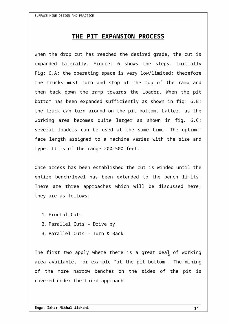
THE PIT EXPANSION PROCESS
When the drop cut has reached the desired grade, the cut is expanded laterally. Figure: 6
shows the steps. Initially Fig: 6.A; the operating space is very low/limited; therefore the
trucks must turn and stop at the top of the ramp and then back down the ramp towards the
loader. When the pit bottom has been expanded sufficiently as shown in fig: 6.B; the
truck can turn around on the pit bottom. Latter, as the working area becomes quite larger
as shown in fig. 6.C; several loaders can be used at the same time. The optimum face
length assigned to a machine varies with the size and type. It is of the range 200-500 feet.
Once access has been established the cut is winded until the entire bench/level has been
extended to the bench limits. There are three approaches which will be discussed here;
they are as follows:
1. Frontal Cuts
2. Parallel Cuts – Drive by
3. Parallel Cuts – Turn & Back
The first two apply where there is a great deal of working area available, for example “at
the pit bottom”. The mining of the more narrow benches on the sides of the pit is covered
under the third approach.
Figure: 6 AStep I
Engr. Izhar Mithal Jiskani 11

SURFACE MINE DESIGN AND PRACTICE
Figure: 6 BStep II
.
Figure: 6 CStep III
Figure 6: Detailed steps in the development of a new production level
FRONTAL CUTS:The frontal cut is shown diagrammatically in figure – 7.
The shovel faces the bench face and begins digging forward straight ahead and to the
side. A niche is cut in the bank wall. For the case shown, double spotting of the trucks is
used. The shovel first loads to the left and when the truck is full he proceeds to the other
truck on the right. The swing angle varies from 1100 (maximum) to an angle of 100
(minimum). The average swing angle is about 600; hence the loading operation is quite
effective. There must be room for trucks to position them around the shovel. The shovel
Engr. Izhar Mithal Jiskani 12

SURFACE MINE DESIGN AND PRACTICE
penetrates to the point that the face. It then moves parallel to itself and takes another
frontal cut as shown in fig: 7.1;
With a long face and sufficient bench width, more than one shovel can work the same
face, as shown in fig. 7.2.
1. DRIVE BY CUTS :- (parallel cuts-drive by)
Another possibility when the mine geometry allows is the parallel cut with drive by. This
is diagrammatically shown in figure 8. The shovel moves across and parallel to the
digging face. For this case bench access for the haul units must be available from both the
directions. It is highly efficient for both the trucks and the loader. Although the average
swing angle is greater than for the frontal cut, the trucks do not have to back up to the
shovel and the spotting is simplified.
2. TURN AND BACK:- (Parallel cuts-turn and back)
The expansion of the pit at the upper levels is generally accomplished by using parallel
cuts. Due to space limitations there is only access to the ramp from one side of the shovel.
This means that the trucks approach the shovel from the rear. Then, they stop, turn, and
back into the load position.
Sometimes there is a room for double spotting of the trucks (fig: 9.1) but sometimes for
only single spotting as shown in figure 9.2.
Engr. Izhar Mithal Jiskani 13
SURFACE MINE DESIGN AND PRACTICE
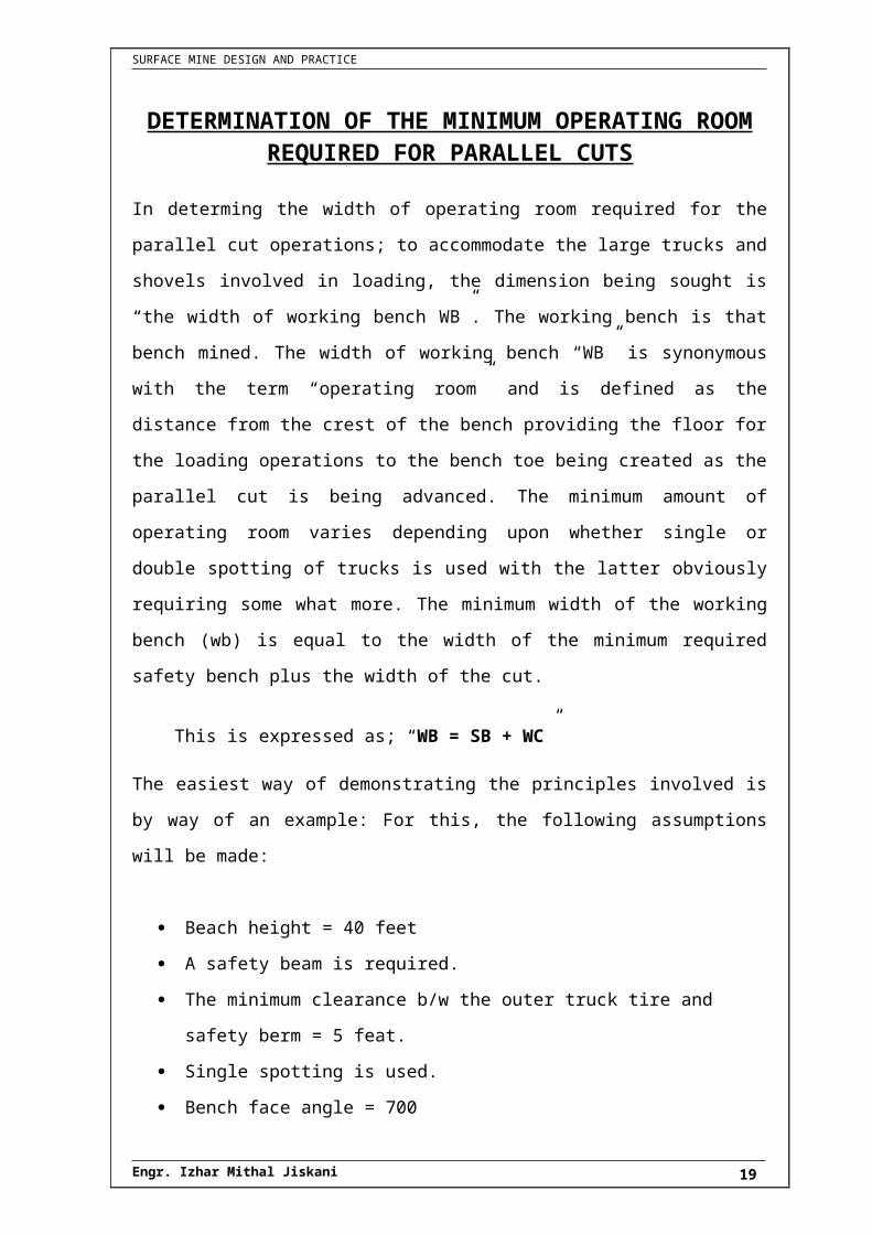
DETERMINATION OF THE MINIMUM OPERATING ROOM REQUIRED FOR PARALLEL CUTS
In determing the width of operating room required for the parallel cut operations; to
accommodate the large trucks and shovels involved in loading, the dimension being
sought is “the width of working bench WB”. The working bench is that bench mined. The
width of working bench “WB” is synonymous with the term “operating room” and is
defined as the distance from the crest of the bench providing the floor for the loading
operations to the bench toe being created as the parallel cut is being advanced. The
minimum amount of operating room varies depending upon whether single or double
spotting of trucks is used with the latter obviously requiring some what more. The
minimum width of the working bench (wb) is equal to the width of the minimum required
safety bench plus the width of the cut.
This is expressed as; “WB = SB + WC”
The easiest way of demonstrating the principles involved is by way of an example: For
this, the following assumptions will be made:
Beach height = 40 feet
A safety beam is required.
The minimum clearance b/w the outer truck tire and safety berm = 5 feat.
Single spotting is used.
Bench face angle = 700
Loading is done with a 9yd3 Shovel.
Haulage is done by 85 ton capacity Trucks.
Truck width = 16 feet
Tire Rolling radius = 4 feat.
The general arrangement of working bench (in x-sectional view) is shown in figure 10.
Engr. Izhar Mithal Jiskani 14

SURFACE MINE DESIGN AND PRACTICE
Figure 10:
.Figure 10.1: Simplified representation of berm.
kl
The design shows that:-
Working bench width = 102 feet
Cut width = 60 feet
Safety bench width = 42 feet.
The basic calculations (justifications) behind these calculations are presented as follows.
Engr. Izhar Mithal Jiskani 15
SURFACE MINE DESIGN AND PRACTICE
Step # 01:- Highest of the berm should be at least same as the radius of the
truck tire, i.e.; = 4 feet.
Step # 02:- The distance b/w the crept and centre line of the truck = Tc = 21:
Width of Berm = 8 feet.
Clearance distance b/w safety berm and the wheels of truck = 5 feet
and; the total width of truck = 16 feet.
Step # 03:- The distance b/w the centre line of the Shovel and centre line of the
truck is also called as “Dumping radius” denoted by B; B = 45.5
feet.
Step # 03b:- The Maximum duping height (A) is more than sufficient to clear
the truck;
A = 28 feet.
Step # 03c:- Distance b/w the centre line of Shovel and toe = G ;
G= 35.5 feet
Step # 04:- The desired working bench dimensions become ;
Total minimum width of working bench = WB = TC +B+G;
:. WB = 21 feet + 45.5 feet + 35.5 feet.
WB = 102 feet
Note: All the parameters and /or dimensions used above, depends upon the size of the
machinery which is used.
WIDTH OF CUT :- (Wc)
The corresponding width of cut is:-
WC = 0.90 × 2 × G = 0.90 × 2 × 35.5 feet
WC = 63.9 feet
Engr. Izhar Mithal Jiskani 16

SURFACE MINE DESIGN AND PRACTICE
Note: This is applied to the width of the pile of broken material. Therefore, to allow for
swell and throw of the material during blasting. The design cut width should be less than
this value. Thus a value of 60 feet has been assumed.
WIDTH OF SAFETY BENCH :- (SB)
Knowing the width of working bench, and width of cut, the resulting safety bench has a
width of; SB = WB – WC ;
:. SB = 102-60 = 42 feet.
SB = 42 feet.
Note: This is of the order of the bench height (40ft) which is a rule of thumb, sometimes
employed.
Engr. Izhar Mithal Jiskani 17
SURFACE MINE DESIGN AND PRACTICE
CUT SEQUENCINGS:
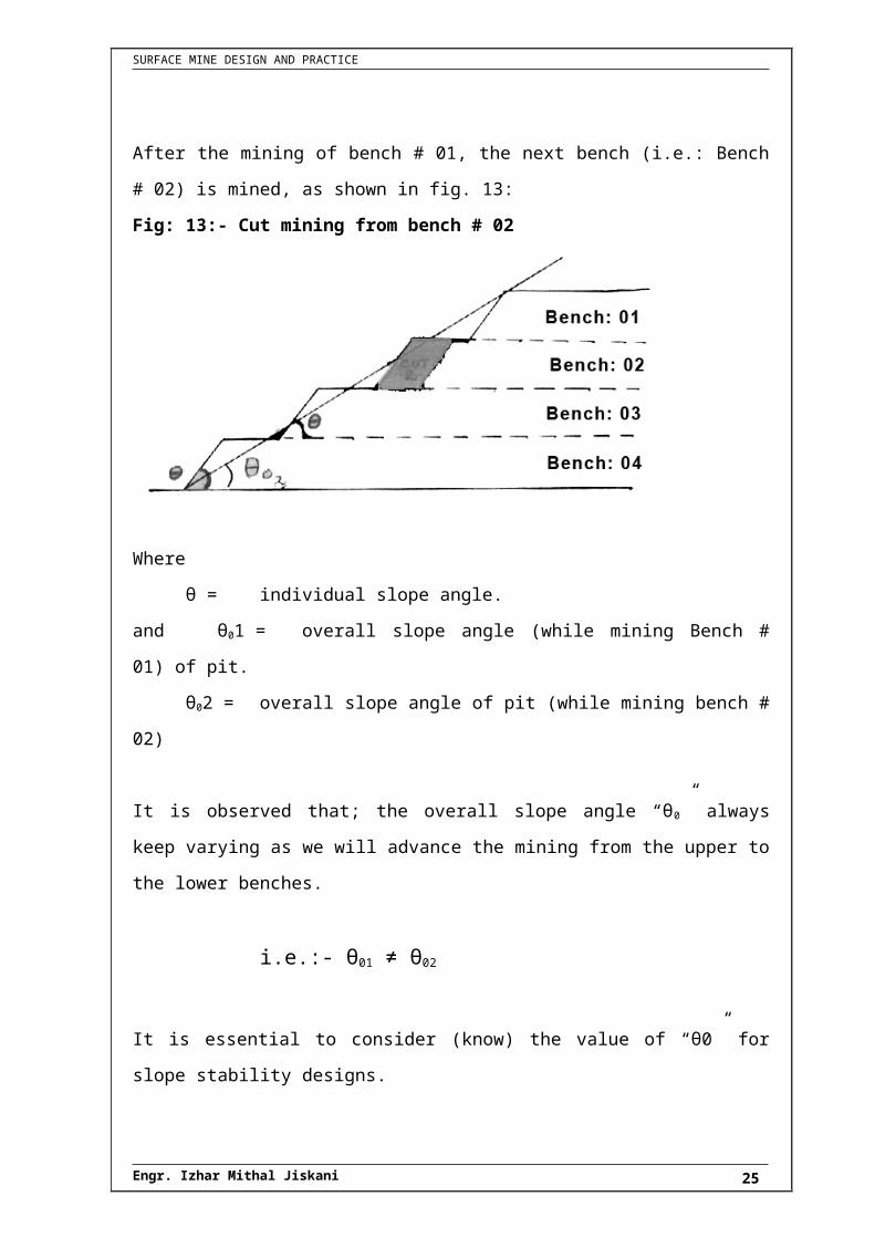
Let us consider a pit consisting of four benches as shown in fig: 11
Fig. 11: Initial Geometry of the pit:
After the initial geometry of the bench is completed; the mining of first bench is started as
shown in figure: 12.
Fig. 12: Mining of bench # 01
The above figure shows that while performing the cut mining operation of bench # 01, the
overall slope angle was “θ01”.
After the mining of bench # 01, the next bench (i.e.: Bench # 02) is mined, as shown in
fig. 13:
Engr. Izhar Mithal Jiskani 18
SURFACE MINE DESIGN AND PRACTICE
Fig: 13:- Cut mining from bench # 02
Where
θ = individual slope angle.
and θ01 = overall slope angle (while mining Bench # 01) of pit.
θ02 = overall slope angle of pit (while mining bench # 02)
It is observed that; the overall slope angle “θ0” always keep varying as we will advance
the mining from the upper to the lower benches.
i.e.:- θ01 ≠ θ02
It is essential to consider (know) the value of “θ0” for slope stability designs.
Engr. Izhar Mithal Jiskani 19

SURFACE MINE DESIGN AND PRACTICE
PIT SLOPE GEOMETRY
There are a number of “slopes” which enter into “pit design”. Care is taken so that there is
no confusion as to how they are calculated and what they mean. One slope has already
been introduced. That is the ‘bench face angle” (shown in figure). It is defined as the
angle made with the horizontal of the line connecting the Toe to the crest “this def:” will
be maintained through this piece of literature.
Now consider the slope consisting of “5” such benches (shown in figure). The angle made
with the horizontal of the line connecting the lowest most toes to the upper most crests is
defined as the overall pit slope.
Height of each bench = y = 50 feet.
Horizontal distance = x = 35 feet
Distance under slope = x’ =?
Bench face angle = 750 = θ
:.
Since we have 5 benches,
i.e.: - 5 slopes, X= (4*x) + (5*x’).
X = (4 x 35) + (5 x 13.4) = 140 + 67 X = 207’
Y = 5 x 50 Y = 250’
:. Overall pit slope angle = θ overall
207
250 tan
x
y tanθ 11
overall
Ooverall 0.45 θ
Engr. Izhar Mithal Jiskani 20

SURFACE MINE DESIGN AND PRACTICE
INTRODUCING RAMP IN PIT SLOPE GEOMETRY
An access ramp with a width of 100 feet; introduced at the half way up bench 3, the
overall pit slope becomes;
x
y tanθ 1
overall
where, Y = 250’
100' tan75
5x50 4x35 X and
O
:. X = 307 feet.
O1overall 39.18
307
250tanθ
Ooverall 39.2θ
It can be seen that the presence of the ramp n a give section has an enormous impact on
the overall slope angle.
Fig. 15: Overall slope angle with ramp included.
Engr. Izhar Mithal Jiskani 21

SURFACE MINE DESIGN AND PRACTICE
INTER-RAMP SLOPE ANGLES AFTER RAMP INCLUDED
The ramp breaks the overall slope angles “ overall” into 2 portions as shown in following
figure; each of these 2 portions can be described by slope angles. These angles are called
as “the Inter ramp (Between the ramps)” angles.
Figure 16: Inter ramp slope angles after ramp included
The inter-ramp wall height is 125 ft for each segment. Generally the inter ramp wall
heights and angles for different slope segments would not be the same. From a slope
stability view point each inter-ramp segment would be examined separately.
Engr. Izhar Mithal Jiskani 22

SURFACE MINE DESIGN AND PRACTICE
INTRODUCING WORKING BENCHES IN PIT SLOPE GEOMETRY
While active mining is underway, some working benches are included in the overall
slope. The fig. ; shows a working bench 125ft in width included as bench 2.
The overall slope angle “ overall” now becomes;
Fig. 17: Overall slope angle with working bench included
Engr. Izhar Mithal Jiskani 23

SURFACE MINE DESIGN AND PRACTICE
INTER-RAMP SLOPE ANGLES AFTER WORKING BENCH INCLUDED
The working bench is treated in the same way as a ramp in terms of interrupting the slope.
Therefore from following figure, two inter-ramp angles are shown:-
As; Y = 250 – 50 = 200 feet and
As; for the above inter ramp angles, the inter ramp heights are,
H1= 50’ and H2 = 2’
Fig. 18: Inter-ramp slope angles after working bench included
Engr. Izhar Mithal Jiskani 24
SURFACE MINE DESIGN AND PRACTICE
PLANNAR FAILURE
Fig. 19: Perspective
view of plannar
failure.
Fig. 20: Dimensions and forces in a rock slope with a potential failure plane.
As figure 20 shows the dimensions and forces in a rock slope with potential failure plane.
The Mohr-coulomb failure criterion has been used.
The following definitions apply:
i= average slope angle from horizontal in degrees,
ß = the angle of discontinuity from the horizontal (degrees),
W =block weight;
Engr. Izhar Mithal Jiskani 25

SURFACE MINE DESIGN AND PRACTICE
R = resisting force;
C = cohesion,
φ =friction angle.
Wcosß= normal force
Wsinß= driving force
A= Area of the failure plane.
The factor of safety ‘F’ is defined by the following equation:
sliding induce to tendingForce
slidingresist toavailable force TotalF
For the case shown in Fig:”20”
βWsin
tanφβ WcoscAF
If there is water present then;
VβWsin
tanφtU-β WcoscAF
where,
U= water pressure along potential failure surface,
= friction angle (affected by water),
V= force along potential sliding plane.
Engr. Izhar Mithal Jiskani 26

SURFACE MINE DESIGN AND PRACTICE
Example # 01:-The average planned slope angle i = 700, the orientation of the potential failure plane ß =
500 and the friction angle φ = 300. The thickness of he plane is 1ft; the cohesion is 1600
lb/ft3. The unit weight of the rock is 160 lb/ft3, and height of the wall is 100ft.
Sol:-
force Sliding
force frictionalS.F
tanφWcosβcA force Frictional
Fig. 21 (a)
Fig. 21 (b)
B
CAb
sin
sinsin
2
1 2
(a)
A
CBa
sin
sinsin
2
1 2
(b)
C
CAc
sin
sinsin
2
1 2
(c)
as, bb
HB
100sin
Engr. Izhar Mithal Jiskani 27

SURFACE MINE DESIGN AND PRACTICE
or130.54feet
0.766
100
sin50
100b
0
Putting the above value in eqn (a).
2
0
002
62.2375
279.09396.0
262.0692.17040
2
1110sin
50sin20sin54.130
2
1
ft
(V) Volume of (triangle ABC) sliding block = thickness of sliding block
1ft2375.62 31ft2375.62V
(W) Weight of sliding block is = volume × unit weight
s380099.2lbW
160lb/ft2375.62γVW 3
As
Wsinβ
WcosβcosβcAF
A= Area of the failure plane, and
A= length of failure plane × thickness
A= b × 1ft= 130.54ft × 1ft
A= 130.54ft2
1.2F291172.88
349838.4F
291172.88
0.577244323.05130.541600F
0.577Tan30Tanφ
1600lb/ftc
b291172.88lsin50380099.2Wsinβ
b244323.05lcos50380099.2Wcosβ
0
2
0
Engr. Izhar Mithal Jiskani 28

SURFACE MINE DESIGN AND PRACTICE
By using “graphical simplification” of the S.F;
10Y
/1600100160Y
γγH/function height slope Y
40Xor
400function angle SlopeX
30505070φββiX2
22
Now by using slope design chart for plane
failure the safety factor for X= 40 and Y= 10
is;
S.F = 1.6
Engr. Izhar Mithal Jiskani 29

SURFACE MINE DESIGN AND PRACTICE
Example 02:
Determine the limiting pit slope angle (i) using the following data:
i. Inclination of failure plane 0β50
ii. Angle of internal friction 0φ35
iii. Cohesion = 3mkg7800C
iv.3mtons2.5γ
v. Height of slope = 150m
Solution:
48.07Y7.8
375
7800
1502.5
c
γHY
From the slope design chart, at Y=48 and S.F = 1.0, X=18
:. We know that iX 2
75013i2355050i218
Now, squaring both sides
0
0
22
4.55
4.5560
3324
3324300032460
300060324
750154324
75015218
i
i
i
i
i
i
Engr. Izhar Mithal Jiskani 30

SURFACE MINE DESIGN AND PRACTICE
Slope design chart for plane failure including various safety factors (Hoek, 1970a)
Engr. Izhar Mithal Jiskani 31

SURFACE MINE DESIGN AND PRACTICE
Example 03:
Determine the height of slope using the following data.
i. Slope angle 065i
ii. Inclination of failure plane 0β50
iii. Angle of internal friction 053
iv. Cohesion27800c mkg
v. Unit wt: of rock 3m2.5tγ ;
vi. Safety factor = S.F = 1.4;
Sol:
0
2
22
30X
15225521515
35505065φββiX
By using the graph of “slope design chart for plane failure including various safety
factors”
At 1.4 S.F and30X 0
The value of Y=16
:. As ,
c
HY
49.92mH
49.92m2.5
780016
γ
cYH
Engr. Izhar Mithal Jiskani 32

SURFACE MINE DESIGN AND PRACTICE
CIRCULAR FAILURE
Fig. 22 (a):
Plane failure in rock with highly
ordered structure, such as state
.
Fig. 22 (b): Free body diagram
As we know that;
dwMw0.;McMw
0ΣM
Engr. Izhar Mithal Jiskani 33

SURFACE MINE DESIGN AND PRACTICE
length of Arc ‘AB’ in fig:22(b); Rθ
Area of Arc ‘AB’= length × thickness
[For simplicity, here we have considered the value of thickness of Arc as Unit]
Area of Arc ‘AB’ = 1Rθ
Mc = (Area of Arc) × (cohesion) × (R)
θCRMc
RCRθ2
as, Mw+Mc= 0
wd
θCRS.For
θCRwd
0θCRwd
2
2
2
If the portion is in equilibrium state,
it is stable, and will not slip down.
Engr. Izhar Mithal Jiskani 34

SURFACE MINE DESIGN AND PRACTICE
Example: A cutting in saturated clay inclined at a slope of 1 vertical and 1.5 horizontal and has a
vertical height of 10.0 m. the bulk unit weight of soil is 18.5 KN/m3 and its un-drained
cohesion is 40 KN/m2. Determine the safety factor against immediate shear failure along
the slip circle as shown in figure.
Figure 23
Soln:
1 vertical Slope
1.5 horizontal Slope
2
3
mKN40C
mKN18.5λ
From fig: 23, consider “ afo Δ ” to find out ‘ 1θ ’
01
11
16.7θ
16.7m
5mTanθ
According to Pythagoras theorem,
17.43mR
303.9R
303.0278.92516.75R
BaseperpHyp222
222
1φ ?; since given slope of cutting plane “ad” is 1 vertical and 1.5 horizontal;
Thus,0
1
11
33,7φ
1.5
1Tanφ
from figure 23; it is clear that:
Engr. Izhar Mithal Jiskani 35

SURFACE MINE DESIGN AND PRACTICE
0
0000
110
39.6φ
39.616.733.790
θφ90φ
Now we consider right angled “oec”
22.6φ
67.490180φ
67.4θ
0.384cosθ
17.43
6.7cosθ
3
003
02
12
2
From obe Δ we get 2 , as follows,
0
00
000
0
00011
0
03
003
00021
03
02
12
56.3Ψ
123.7180Ψ
39.684.1180φθ180Ψ
84.1φ
16.733.790θφ90φ as
123.71φ56.3180φ
22.633.7180φφ180φ
22.6φ17.43
6.7sinφ
Area of sinΨ
sinφsinθR
2
1ΔΔaod 2
1
21
0
002
1
115.85mΔ
56.3sin
39.6sin84.1sin17.43
2
1Δ
In order to find the area of bcd , we must know any one side of bcd . Let’s find “DB”
for sake of ease.
sinΨ
R
sinφ
OD and ODRDB
Engr. Izhar Mithal Jiskani 36

SURFACE MINE DESIGN AND PRACTICE
2
2
1
3222
0
0
4.77mΔ
sinφ
sinφsinφ4.07
2
1Δ
4.07mDB13.3617.43DB
13.36m56.3sin
39.6sin17.43
sinΨ
RsinφOD
Now area of polygon oabc=Ap
2120.62mAp
(as) Area of sector
0
2
1802
1 Raoc
2
0
0
222.86mAs
180
π84.117.43
2
1As
Now, Area of slip mass (A)= As-Ap
2102.24mA
120.62222.86A
Volume of slip mass= 1102.24tAV
3102.24mV
Weight of slip mass= γVW
1.44S.F
6.541891.44180
π80.117.4340S.F
Wd
θCRS.F
1891.44KNW
18.5102.24W
002
2
Engr. Izhar Mithal Jiskani 37

SURFACE MINE DESIGN AND PRACTICE
STRIPPING RATIO
Figure 24 (a)
Vm = Vol. of mining
Vc = Vol. of cone
VT = Vol. of truncated portion
:. Vm = Vc- VT
Fig. 24 (b)
Engr. Izhar Mithal Jiskani 38

SURFACE MINE DESIGN AND PRACTICE
As we know that;
Vol: of cone=hπr
3
1 2
And Vol: of cylinder = hπr 2
:. Volume of circular ore body; Vo
Vo= hπr 2……… (1)
Volume of (small) truncated tip of cone; VT
Δhπr3
1V 2
T …… (2) (:.) Height of small cone is ∆h). and γtanθΔh
as height of big cone, is Hc;
and
or
:. Vol: of bigger cone, Vc
(3) γtanθhπR3
1Vcor
Δhhπr3
1HcπR
3
1Vc
2
22
:. Mined Vol: TC VVVm
(4) Δh πr3
1Hπr
3
1V 2
c2
m
Vol: of waste: 0mw VVV
Where, Vol: of Ore hπrV 2
0
:. Vol: of waste (5) VVV 0mw
:. Stripping Ratio
3
3
m ore. of :Vol
m wasteof :VolSR
(6) V
VSR
0
wor 0
w
W
WSR
Engr. Izhar Mithal Jiskani 39

SURFACE MINE DESIGN AND PRACTICE
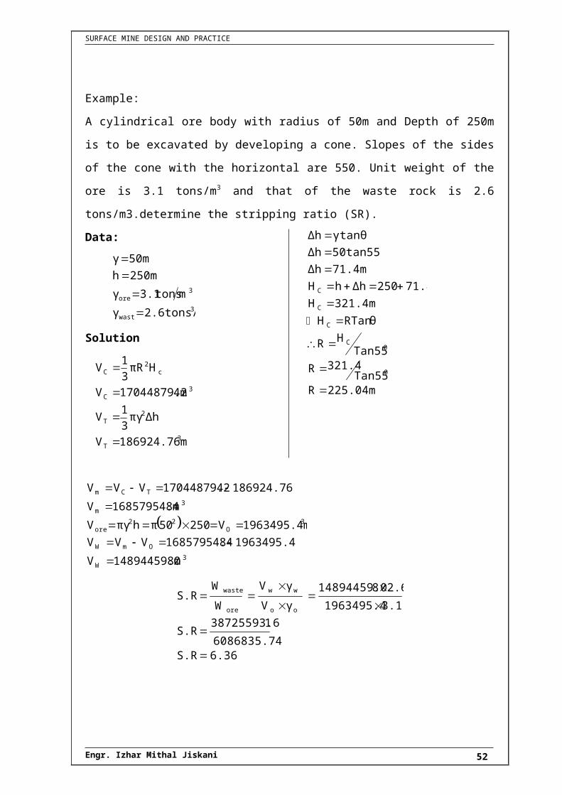
Example:
A cylindrical ore body with radius of 50m and Depth of 250m is to be excavated by
developing a cone. Slopes of the sides of the cone with the horizontal are 550. Unit
weight of the ore is 3.1 tons/m3 and that of the waste rock is 2.6 tons/m3.determine the
stripping ratio (SR).
Data:
3wast
3ore
2.6tons/mγ
mtons3.1γ
250mh
50mγ
Solution
3T
2T
3C
c2
C
186924.76mV
Δhπγ3
1V
4m17044879.2V
HπR3
1V
225.04mRTan55
321.4R
Tan55HR
RTan θH
321.4mH
71.4250ΔhhH
71.4mΔh
50tan55Δh
γtanθΔh
0
0C
C
C
C
3W
OmW
3O
22ore
3m
TCm
8m14894459.0V
1963495.4816857954.4VVV
1963495.4mV25050πhπγV
8m16857954.4V
186924.76417044879.2VVV
6.36S.R6086835.74
138725593.6S.R
3.11963495.4
2.6814894459.0
γV
γV
W
WS.R
oo
ww
ore
waste
Engr. Izhar Mithal Jiskani 40

SURFACE MINE DESIGN AND PRACTICE
DETERMINATION OF “SR” BY AREA METHOD
Ao =Area of sections (i), (ii) and (iii)
Area of Sec: (i) =
21250ft50502
1
Area of Sec: (ii) =20ft50050100
Area of Sec: (iii) =20ft1500501100
2
O
O
27500ftA
150005000212502A
0.36S.R
0.36275000
10000
Ao
AwS.R
10000ftAw
50005000AwAwAw
AwAw since
5000ft1001002
1Aw
2
21
21
21
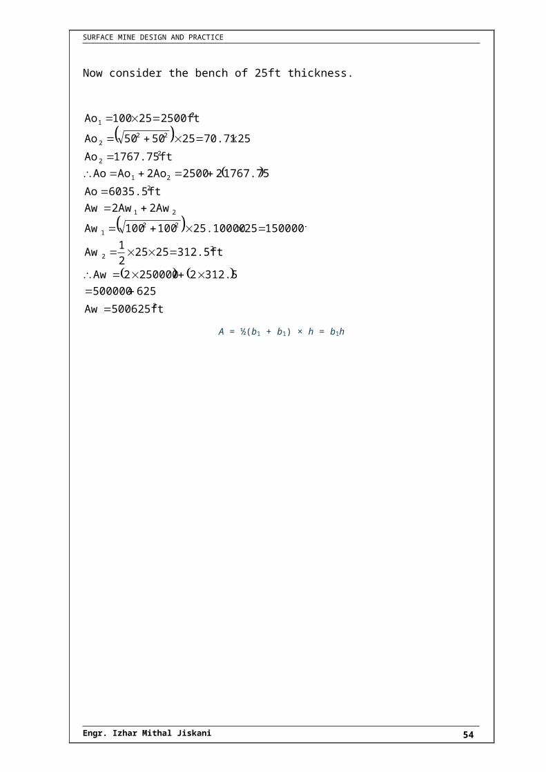
Now consider the bench of 25ft thickness.
Engr. Izhar Mithal Jiskani 41

SURFACE MINE DESIGN AND PRACTICE
2
22
221
21
2
21
22
222
21
500625ftAw
625500000
312.522500002Aw
312.5ft25252
1Aw
150000ft2525.10000100100Aw
2Aw2AwAw
6035.5ftAo
1767.75225002AoAoAo
1767.75ftAo
2570.71255050Ao
2500ft25100Ao
A = ½(b1 + b1) × h = b1h
Engr. Izhar Mithal Jiskani 42

SURFACE MINE DESIGN AND PRACTICE
PIT LIMITS
The minable material becomes that lying
within the pit boundaries. A vertical section
taken through such a pit is shown in figure
A:
The size and shape of the pit depends upon
economic factors and design/production
constraints.
With an increase in price, the pit would expand in size assuming all other factors
remained constant.
The “pit” existing at the end of mining is called the “final pit” or the ultimate pit. In b/w
the birth and death of an open pit mine, there are a series of intermediate pits. This
includes a series of procedures based upon:
Hand Methods,
Computer Methods, and
Computer assisted hand methods
The above mentioned methods are used for developing the pit limits. Within the pit
materials of differing values are found. Economics criteria are applied to assign
destination for these materials based on their value (i.e. mill, waste dump, loach dump,
stock pile etc). Once the pit limits have been determined and rules established for
classifying the in pit materials, then the ore reserves (tonnage and grade) can be
calculated.
The Net Value Calculation:-
The term cut-off grade refers to the “grades” for which the destination of pit material
changes. It should be noted that “grades” were used rather than “grade” since there may
be several possible – destinations. The simplest case is that in which there are two
destinations: the mill or the waste dump. One cut of grade is needed for many operations
today; there are many possible destinations: the mill or leach dump and the waste dump.
Engr. Izhar Mithal Jiskani 43

SURFACE MINE DESIGN AND PRACTICE
Each of the decisions:-
Mill or leach?
Leach or waste?
requires a cut-off grade.
Cut-off Grade:-
The grade at which the mineral resources can’t longer be processed at a profit.
Break-even cut-off grade:-
The grade at which the net value is zero; is called Break-even cut-off grade.
Determination of pit limits, on the basis of net value:
Example:
Determine the pit limits of an open pit mine as shown in figure: setting price of 1m3 of
Ore is US$ 1.9 and mining cost of 1m3 of waste is US$ 1.0.
Sol:
For Strip # 01:-
Vol: of ore (Strip 1) 3
1
1
6.25mVo
11.255Vo
Vol: of waste (Strip 1)
3
1
1
8.74mVw
1.251.252
111.256.364Vw
Engr. Izhar Mithal Jiskani 44

SURFACE MINE DESIGN AND PRACTICE
1.4
Vo
Vw (S.R) Ins S.R
Ins1
1
Value of ore = Vo1* Selling price of 1/m3 of ore
= dollars 11.875US ore of Value
1.96.25
Cost of mining of waste =
1.08.74
waste1m ofcost Mining Vw 31
Cost of mining of waste = 8.74 US dollars
Net value = value – cost
= 11.875 – 8.74
N.V = 3.14 US $. → for strip # 01
Calculate for strip, 2, 3 and 4.
For Strip #02:-
32
2
6.25mVo
11.255Vo ore, of Vol.
3
2
22
10.3mVw
1.252111.256.614Vw waste,of Vol.
dollars 1.58USN.V
10.311.875costValueN.V
1.656.25
10.3
Vo
Vw (ins) SR
$ 10.3US110.3 wastemining ofCost
$ 11.875USore of Vol.
1.96.251.9Vo ore of Vol.
2
2
2
For Strip# 03
1.9ins S.R 6.2511.86ins S.R
11.86mVw
1.252111.258.864Vw
6.25mVo
33
23
33
Engr. Izhar Mithal Jiskani 45

SURFACE MINE DESIGN AND PRACTICE
dollars US0.015N.V
11.86-11.875N.V
dollars US11.86111.86 wasteofCost
dollars US11.8751.96.25ore of Value
For Strip # 04:-
dollars -1.55USN.V
13.424-11.875 N.V
$ 11.8751.96.25 ore of ePrice/valu
$ 13.424113.424 wastemining ofCost
2.146.25
13.424
Vo
VwInsS.R
13.424mVw
0.7812512.6425Vw
1.252111.2510.114Vw
6.25Vo
4
4
34
4
24
4
As can be seen that the net value changes from (+) to (-) as the pit is expanded, sometimes the N. V become zero, so that this pit position is termed as “Break-even”, which is the location of final pit wall.
Now for overall volume of waste we have;
dollars US68.8N.V
49.00-117.8 (overall) value-N
dollars US49.00149 wasteofcost mining overall
dollars US117.81.962ore of valueoverall
0.80.796249
VoVwratio strippig overall
62more of : voloverall
1m12.549.5
15521159.9 ore of : voloverall &
49m wasteof : voloverall
1 thickness49m
9.99.92
1Δw
3
3
2
Engr. Izhar Mithal Jiskani 46

SURFACE MINE DESIGN AND PRACTICE
Example
Copper ore is milled to produce a copper concentrate. This mill concentrate is slipped and
transported to a smatter and the resulting blister copper is eventually refined.
In this example, the following data will be assumed.
Mill recovery rate = 80%
Mill concentrate grade = 20%
Smelting loss = 10 lbs/st of concentrate
Refining loss = 5 lbs/st of blister copper.
The ore is containing 0.55%, All the costs and revenues will be calculated in terms of 1
ton of ore. Note that ore short ton= 2000 lbs .
Solution:-
Step # 01:- Complete the amount of saleable copper (lb/s per st of ore)
a) Contained copper (cc) is :-
11.00lbs100
0.55 * 2000lb/st cc
b) Copper recovered by mill (RM/st of ore)
8.8lbs100
8011lbsRM
c) Concentration ratio (r):- the ratio of concentration is defined as
45.45r
45.458.8
400
8.8
100202000r
ore ofst recovered/ cu"" of lbs
econcentrat ofcu/st of lbsr
d) Copper recovered by smelter :- (R.S)
As, smelting loss = 10 lbs/st of concentrate.\
Economic Block Models:-
The block model representation of ore bodies rather than section representation and the
storage of the information on high speed computers have offered some new possibilities
in open pit mines.
Engr. Izhar Mithal Jiskani 47

SURFACE MINE DESIGN AND PRACTICE
ORE GRADE ESTIMATIONby the constant distance weighting techniques
a) Inverse Distance Techniques:-
The formula to calculate the ore grade by inverse distance technique is :
dii
digi
Σ
Σn
1i
n
1i
Where,
gi= given grade of ore at a point.
g= estimated grade of ore.
di= distance b/w known point and point of estimation.
Example:
Calculate the estimated grade of ore at point “C”, using inverse distance technique.
Known grades of an ore at points C1-C6 ore shown in fig: [in brackets]
Sol:
Engr. Izhar Mithal Jiskani 48

SURFACE MINE DESIGN AND PRACTICE
First let’s estimate the value of distances d1, d2...d6 by using Pythogona’s theorem.
316.23md100000300100d
223.6md50000100200d
282.84md80000200200d
223.6md50000200100d
316.23md100000100300d
282.84md8000200200d
622
6
522
5
422
4
322
3
222
2
122
1
As we know that;
1
6
6
2
1
1
1
6
6
2
2
1
1
104.484g0.0223
0.0100g
316.231
223.61
282.841
223.61
316.231
282.841
316.23
0.644
223.6
0.023
282.84
1.365
223.6
0.258
316.23
0.165
282.84
0.409
g
ddd
dg
dg
dg
g
:. The estimated grade of ore =g
g = 0.45 %
b) Inverse Distance Squared weighting Technique:-
Using this technique, the grade of ore is found, by using following equations.
2
n
1i
2
n
1i
di
1di
gi
g
Σ
Σ
Using the data of previous example; calculate the grade of ore by squared weighting
technique.
Engr. Izhar Mithal Jiskani 49

SURFACE MINE DESIGN AND PRACTICE
22
66
2255
2244
2233
2222
2211
9m100001.412d ---------- 316.23md
49996.96md ---------- 223.6md
m79998.4656d ---------- 282.84md
49996.96md ---------- 223.6md
9m100001.412d ---------- 316.23md
m79998.4656d ---------- 282.84md
0.422%g108.5003
103.5885g
d1
d1
d1
d1
dg
dg
d
g
d
g
g
5
5
26
25
22
21
26
62
5
52
2
22
1
1
Engr. Izhar Mithal Jiskani 50

SURFACE MINE DESIGN AND PRACTICE
ORE RESERVE ESTIMATIONby Triangular Method
From above figure:
Area of rectangle abcd= 3213 yyxx
Area of 12121 yyxx
2
1ΔA
Area of 32232 yyxx
2
1ΔA
Area of 31133 yyxx
2
1ΔA
Area of 321 ΔAΔAΔA- abcd of Area ΔA
1
yyxx
yyxx
yyxx
2
1yyxx
3113
3223
1213
3213
Example:Calculate the above of ΔA by using ore reserve estimation:
Easting (x)m Northing (y)m
1100 1200
1500 1200
1100 800
Solution:-
Let
Engr. Izhar Mithal Jiskani 51
SURFACE MINE DESIGN AND PRACTICE
mym
mym
mym
800,1100x
1200,1500x
1200,1100x
33
22
11
From given table.
And we know that;
311332
2332133213 yyxxyy
xxyyxx
2
1yyxxA
280,000mA
1600002
1
01600002
10
8001200110011008001200
150011001200120011001100
2
1800120011001100A
OR
280,000mΔA
16000021
4004002
1
hb2
1ΔA
Engr. Izhar Mithal Jiskani 52

SURFACE MINE DESIGN AND PRACTICE
Example:
Calculate the ore reserves in area, as shown in following figure. Density of the ore is
given as 2.5 tons/m3
Solution:-As we know that:
2
321
145000mΔA
205000350000
300500213004002
120070021700500
ΔAΔAΔA - abcd of AreaΔA
Average thickness of ore = 3321 CCC
4mt
4m3
12
2
453t
:av
:av
Vol: of ore in Triangular area= :avtΔA
Vol. of ore = 145000×4mVol. of ore = 580000m3.;. Ore reserves = 580000×2.5
Ore reserves = 1450000
Engr. Izhar Mithal Jiskani 53
SURFACE MINE DESIGN AND PRACTICE
Calculation Of Thickness Of Ore In A Drill HoleLength of “t”ore body (m)
Grade (%)“g”
Length × grade(t×g)
0.6t1 0.59g1 11gt
1.4t 2 0.48g 2 22gt
1.4t 3 0.6g 3 33gt
4.1t 4 0.56g 4 44gt
1.3t 5 0.32g 5 55gt
:. Average thickness = (tav:)
(1)------- ti
tigi
Σ
Σn
1i
n
1i
0.503m t6.1
3.066 t
1.31.41.41.40.6
0.321.30.561.40.61.40.481.40.590.6 t
:av
:av
:av
Calculation Of Reserves Using Weight Age Average Thickness:
Calculate the reserves of ore shown in above fig: having a density of 1.35 tons/m3 by
using the weight age average thickness, when; t1=40m, t2=60m, t3=50m
Solution: the weight age average thickness is calculated as:
Engr. Izhar Mithal Jiskani 54

SURFACE MINE DESIGN AND PRACTICE
0
1
00031
02
000213
00011
02
112
01
111
0
11
332211
w
55.49θ
82.8741.64180φφ180θ
82.8756.3126.56φφθ
41.6426.5668.2φφθ
56.31φ
1.5tan400600
500800tanφ
26.56φ
0.5tan400600
300500tanφ
68.2
2.5tan200400
300800tanφ
:fig above from
(1) 360
θtθtθt
t
Substitute the values of t1, t2, t3, θ 1, θ 2, θ 3 in equation 1
3
152.3 tw
360
9138.5
tw
360
82.87) x (50 55.49) x (60 41.64) x (40
tw
tw = 50.77 m
∆ A = Area of abcd – [∆A1, ∆A2, ∆A3]
∆ A = (400 x 500) – [ (½ x 500 x 200) + (½ x 300 x 200) + (½ x 400 x 200) ]
∆ A = 200000 – 120000
∆ A = 80000 m2
Volume of A = A x tw = 80000 x 50.77
:. Volume of A = 4061600 m3
:. Ore reserves = Volume x density
= 4061600 m3 x 1.35 t/m3
= 5483160 tons
Engr. Izhar Mithal Jiskani 55

SURFACE MINE DESIGN AND PRACTICE
Example:
In a level terrain, determine the max height of high wall that dragline can strip without re-
handling, using the following data:
Dumping radius =(Rd)= 47m,
Outside diameter of tub = (Et) = 11m,
Spoil angle of repose ( ) =370
High wall angle = ( φ ) = 8740
Pit width =(w) = 15m
Sean thickness = (T) = 1.22 m
Swelling factor = (Ps) = 30 %
Solution:
As we know that
Rd = Re + So
.: Re = Rd – So -------> 1 and So = 0.75 Et.
Re = 47 – (0.75 Et)
Re = 47 – (0.75 ×11)
Re = 47 – 8.25
Re = 38.75 m
18.2H2.012
36.62H
2.1338.752.012H
2.132.0121H38.75
1.6193.7481.7251H0.287H
1.222.8251.3H1.3270.287H
1.22tan374
15
100
301Hcot37Hcot7438.75
Ttanθ4
W
100
Ps1HcotθHcotφRe
000
Engr. Izhar Mithal Jiskani 56