Embed Size (px)
Citation preview
z Computer Graphics, 26,2, July 1992
Surface Modeling withOriented Particle Systems
Richard Szeliskit and David Tonnesen$
tlligltal EquipmentCorp.,Cambridge Research Lab, One Kendall Square, Bldg. 700, Cambridge, MA 02139
lDept.of Computer Science, University of Toronto, Toronto, Canada M5S 1A4
AbstractSplines and deformable surface models are widely used in computergraphics to describe free-form surfaces. These methods require
manual preprocessing to discretize the surface into patches and to
specify their connectivity. We present a new model of elastic sur-faces based on interacting particle systems, which, unlike previoustechniques, can be used to sptiL join, or extend surfaces withoutthe need for manual intervention. The particles we use have long-range attraction forces and short-range repulsion forces and followNewtonian dynamics, much tiie recent computational models offluids and solids. To enable our particles to model surface elementsinstead of point masses or volume elements, we add an orientationto each particle’s state. We devise new interaction potentials for
our oriented particles which favor locally planar or spherical ar-rangements. We atso develop techniques for adding new particlesautomatically, which enables our surfaces to stretch and grow. Wedemonstrate the application of our new particle system to modefingsurfaces in 3-D and the interpolation of 3-D point sets.
Keywords: Surface interpolation, particle systems, physically-based modeling, oriented particles, self-organizing systems, sim-ulation.CR Categories and Subject Descriptors: 1.3.5 [Computer Graph-ics]: Computational Geometry and Object Modeling — Curve, sur-jace, solid, and object represe~adons; 1.3.7 [Computer Graphics]:Three-Dimensional Graphics and Realism — Animation.
1 IntroductionThe modeling of free-form surfaces is one of thecentraf issuesof computer graphics. Spline models [3, 8] and deformablesurface models [25] have been very successful in creatingand animating such surfaces. However, these methods ei-ther require the discretization of the surface into patches (forspline surfaces) or the specification of local connectivity (for
spring-mass systems). These steps can involve a significantamount of manual preprocessing before the surface modelcan be used.
For shape design and rapid prototyping applications, werequire a highly interactive system which does not force thedesigner to think about the underlying representation or belimited by its choice [18]. For example, we require the basic
Permission [u copy without fee all or part nf this material is grantedprnvided that the copies are not made or distributed for directcommercial advantage. the ACM copyright nntice and the title of thepublication and its date appear. and notice is given tha[ copying is bypermission of the Asstxiatinn for Cnmputing Machinery. To copyotherwise, or tn republlsh, requires a fee and/or spxitic permission.
abilities to join severrd surfaces together, to split surfacesalong arbitrary lines, or to extend existing surfaces, withoutspecifying exact connectivity. For scientific visualization,
data interpretation, and robotics applications, we require a
modeling system that can interpolate a set of scattered 3-D
data without knowing the topology of the ‘surface. To con-struct such a system, we will keep the ideas of deformationenergies from elastic surface models, but use interacting par-ticles to build our surfaces.
Particle systems have been used in computer graphics
by Reeves [16] and Sims [21] to model natural phenomena
such as fire and waterfalls. In these models, particles moveunder the influence of force fields and constraints but donot interact with each other. More recent particle systems
borrow ideas from molecular dynamics to model liquids andsolids [12, 26, 29]. In these models, which have sphericallysymmetric potentiaf fields, particles arrange themselves intovolumes rather than surfaces.
In this paper, we develop orienfedparlicles, which over-
come this natural tendency to form solids and prefer to formsurfaces instead. Each particle has a local coordinate frame
which is updated during the simulation [171. We de-
sign new interaction potentials which favor locally planar orlocally spherical arrangements of particles. These interac-tion potentials are used in conjunction with more traditionallong-range attraction forces and short-range repulsion forceswhich control the average inter-particle spacing.
Our new surface model thus shares characteristics of
both deformable surface models and particle systems. Liketraditional spline models, it can be used to model free-formsurfaces and to smoothly interpolate sparse data. Like in-
teracting particle models of solids and liquids, our surfacescan be split, joined, or extended without the need for re-pararneterization or manual intervention. We can thus useour new technique as a tool for modeling a wider range ofsurface shapes.
The remainder of the paper is organized as follows.
In Section 2 we review traditional splines and deformable
surface models, as well as particle systems and the poten-tial functions traditionally used in molecular dynamics. InSection 3 we present our new oriented particle model and
the new interaction potentials which favor locally planar andlocally spherical arrangements. Section 4 presents the dy -
!(1199~ ACM-O-8979 1-479- I /92/007/0185 sol.50 185
—
SIGGRAPH ’92 Chicago, July 26-31, 1992
namics (equations of motion) associated with our interacting
particle system and discusses numerical time integration andcomplexity issues. Section 5 discusses alternative renderingtechniques for particles and surfaces. In Section 6 we presentsimple shaping operations for surfaces built out of pwticles.In Section 7 we show how to extend existing surfaces by
adding new particles, and how to use this approach to auto-matically fit surfaces to 3-D point collections. In Section 8 we
discuss applications of our system to geometric modeling.
2 BackgroundOur new surface modeling technique is based on two pre-viously separate areas of computer graphics, namely de-formable surface models and particle systems. Below, wepresent a brief review of these two fields.
2.1 Deformable Surface Models
Traditional spline techniques [3,8] model an object’s surface
as a collection of piecewise-polynomial patches, with appro-priate continuity constraints between the patches to achievethe desired degree of smoothness. Within a particular patch,the surface’s shape can be expressed using a superposition ofbasis functions
S(u], IQ) = ~ vil?i(ul, IQ)i
(1)
where S(U1, W) are the 3D coordinates of the surface asa function of the underlying parameters (u1, %), vi are thecontrol vertices, and B~(U1,W) are the piecewise polynomialbasis functions. The surface shape can then be adjusted byinteractively positioning the control vertices or by directlymanipulating points on the surface [2].
Elastically deformable surface models [25] also startwith a parametric representation for the surface S(U1, w).To define the dynamics of the surface, Terzopoulos ef al.[25] use weighted combinations of different tensor (stretching
and bending) measures to define a simplified deformationenergy which controls the elastic restoring forces for thesurface. Additional forces to model gravity, external springconstraints, viscous drag, and collisions with impenetrable
objects can then be added.To simulate the deformable surface, these analytic equa-
tions are discretized using either finite element or finite dif-ference methods. This results in a set of coupled differential
equations governing the temporat evolution of the set of con-trol points. Physically-based surface models can be thoughtof as adding temporal dynamics and elastic forces to an oth-erwise inert spline model. They can also be thought of as
a collection of point masses connected with a set of finite-length springs [26].
Physically-based surface models have been used to
model a wide variety of materials, including cloth [30, 6],
membranes [25], and paper [24]. Viscoelasticity, plasticity,
and fracture have been incorporated to widen the range ofmodeled phenomena [24].
186
------- ------T
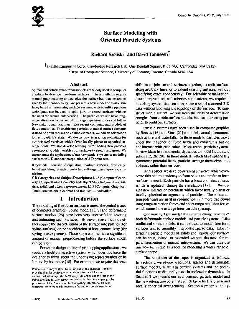
Figure 1: Lennard-Jones type function, ~(r) = B/r” –A/rm. The solid line shows the potentiaJ function ~(r),and the dashed line shows the force function ~(r) =– $~(r).
The main drawback of both splines and deformable sur-face models is that the rough shape of the object must beknown or specified in advance [27]. For spline models, this
means discretizing the surface into a collection of patcheswith appropriate continuity conditions, which is generally adifficult problem [1 1]. For deformable surface models, wecan bypass the patch formation stage by specifying the lo-cation and interconnectivity of the point masses in the finiteelement approximation. In either case, defining the modeltopology in advance remains a tedious process. Furthermore,it severely limits the flexibility of a given surface model.
2.2 Particle Systems
Particle systems consist of a large number of point masses
(particles) moving under the influence of extemat forces suchas gravity, vortex fields, and collisions with stationary obsta-cles. Each particle is represented by its position, velocity,acceleration, mass, and other attributes such as color. Theensemble of particles moves according to Newton’s laws ofmotion. Particle systems built from non-interacting parti-
cles have been used to realistically model a range of naturalphenomena including fire [16] and waterfalls [21]. Interact-ing (oriented) particles have been used to simulate flocks of
“boids” [17].Ideas from molecular dynamics have been used to de-
velop models of deformable materials using collections ofinteracting particles [26, 12, 29]. In these models, long-range attraction forces and short-range repulsion forces con-trol the dynamics of the system. Typically, these forces arederived from an intermolecular potential function such as theLennard-Jones function 4U shown in Figure 1. The force f;j
attracting a molecule to its neighbor is computed from thederivative of the potential function
fi~ = –Vrk(llrijll)j (2)
where r;j = Pj – pi is the vwtor distance betwtxm molecules
z and j (Figure 2).Physical systems whose dynamics are governed by po-
tential functions and damping will evolve towards lower en-ergy states. When extemrd forces are insignificant, molecules
Computer Graphics, 26,2, July 1992
t
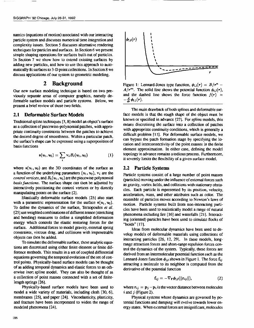
k(Pi, R)
Figure 2: Global and local coordinate frames. The globalinterparticle distance rij is computed from the global coor-dinates pi ttnd Pj of particles i ~d j. The lod distance dijis computed from rij and the rotation matrix I&.
will arrange themselves into closely packed structures tominimize their total energy. For circularly symmetric po-
tential energy functions in 2-D, the molecules will arrange
themselves into hexagonal orderings. In 3-D, the moleculeswill arrange themselves into hexagonally ordered 2-D lay-ers, and therefore make good models of deformable solids[29]. When external forces become huger or internal particleforces smaller, the behavior resembles that of viscous fluids[26, 12]. More sophisticated models of molecular dynamics
are used in simulations of physics and chemistry [10]; how-ever, these are designed for high accuracy and are usually too
slow for animation or modeling applications.
3 Oriented ParticlesWhile particle systems are much more flexible than de-formable surface models in arranging themselves into ar-bitrary shapes and topologies, they do suffer from one majordrawback: in the absence of external forces and constraints,3-D particle systems prefer to arrange themselves into solidsrather than surfaces. To overcome this limitation, we in-
troduce a new distributed model of surface shape which wecall orienled particles, in which each particle represents asmall surface element (which we could call a “surfel”). Inaddition to having a position, an oriented particle also has itsown local coordinate frame, which adds three new degreesof freedom to each particle’s state.
To force oriented particles to group themselves into
surface-like arrangements, we devise a collection of newpotential functions. These potential functions can be derivedfrom the deformation energies of local triangular patches us-
ing finite element analysis [23].Each oriented particle defines both a normal vector (z
in Figure 2) and a local tangent plane to the surface (definedby the local z and y vectors). More formally, we write thestate of each particle as (pi, I&), where pi is the particle’sposition and Ri is a 3 x 3 rotation matrix which defines the
orientation of its local coordinate frame (relative to the globalframe (X, Y, Z)). The third column of R is the local normal
Pi rij Pj Pi rij P]
(a) co-planarity (b) co-normality
L-Yn;Pi rij Pj
(c) co-circularity
Figure 3: The three oriented particle interaction potentials.
The open circles and thin arrows indicate a possible new
position or orientation for the second particle which wouldlead to a null potential.
valor 11~.For surfaces whose rest (minimum energy) configura-
tions are flat planes, we would expect neighboring particlesto lie in each other’s tangent planes. We can express thisco-planarity condition as
h(ni, rij) = (ni - rij)2#(l/rij 11), (3)
i.e., the energy is proportional to the dot product betweenthe surface normal and the vector to the neighboring particle(13gure 3a). The weighting function t(r) is a monotonedecreasing function used to limit the range of inter-particleinteractions.
The co-planarity condition does not control the “twist”in the surface between two particles. To limit this, we intro-
duce a co-normality potential
~N(ni~nj~rij)= [Ini- ‘j[lzt(lkijll), (4)
which attempts to line up neighboring normals, much likeinteracting magnetic dipoles (Figure 3b),
An alternative to surfaces which prefer zero curvature(local planarity) are surfaces which favor constant curvatures.This can be enforced with a co-circularity potential
k(ni, %,rij) = ((ni + ‘j) “‘ij)’+(llrijll) (5)
which is zero when normals are antisymmetrical with respectto the vector joining two particles (Figure 3c). This is thenatural configuration for surface normals on a sphere.
The above potentials can also be written in term of a par-
ticle’s local coordinates, e.g., by replacing the interparticledistance rij by
dij = Rt~lrij = R~l(Pj – pi), (6)
187
SIGGRAPH ’92 Chicago, July 26-31, 1992
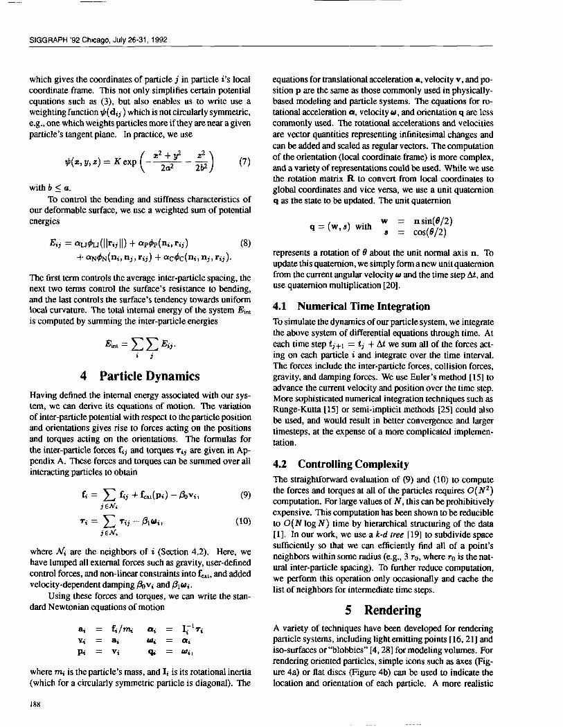
which gives the coordinates of particle j in particle i’s locatcoordinate frame. This not only simplifies certain potentiatequations such as (3), but also enables us to write use aweighting function #(dij ) which is not circularly symmetric,e.g., one which weights particles more if they are near a given
particle’s tangent plane. In practice, we use
( Zz+y= z=#(22, y,z) = Kexp –— – —
2a2 2~)
(7)
with b < u.
To control the bending and stiffness characteristics ofour deformable surface, we use a weighted sum of potentiatenergies
E1j = ~U~U(Ilrajll) + ~p~p(ni, rij) (8)
+ ~N#N(na> nj, rij ) + W+c(ni,nj,rij).
The first term controls the average inter-particle spacing, thenext two terms control the surface’s resistance to bending,and the last controls the surface’s tendency towards uniformlocal curvature. The total internal energy of the system Etitis computed by summing the inter-particle energies
Ekt = ~~Eij.ij
4 Particle Dynamics
Having defined the internal energy associated with our sys-tem, we can derive its equations of motion. The variationof inter-particle potential with respect to the particle positionand orientations gives rise to forces acting on the positionsand torques acting on the orientations. The formulas for
the inter-particle forces fij and torques Tij are given in Ap-pendix A. These forces and torques can be summed over allinteracting particles to obtain
f; = ~ fij + f~~~(pa) – fiVij (9)j CJVi
‘i= ~ Tij ‘~l~i) (lo)
j EN;
where Afl are the neighbors of i (Section 4.2). Here, wehave lumped all external forces such as gravity, user-definedcontrol forces, and non-linear constraints into fe,l, and addedvelocity-dependent damping &vi and ~l~i.
Using these forces and torques, we can write the stan-dard Newtonian equations of motion
at = fi/~ Ui = I,~17i
%= ai ~=~~
~=vi % = Wij
where rni is the particle’s mass, and Ii is its rotationat inertia(which for a circularly symmetric particle is diagonal). The
188
equations for translational acceleration a, velocity v, and po-sition p are the same as those commonly used in physically-based modeling and particle systems. The equations for ro-tational acceleration a, velocity w, and orientation q are lesscommonly used. The rotational accelerations and velocities
are vector quantities representing infinitesimal changes and
can be added and scaled as regular vectors. The computation
of the orientation (local coordinate frame) is more complex,and a variety of representations could be used. While we usethe rotation matrix R to convert from local coordinates toglobal coordinates and vice versa, we use a unit quatemionq as the state to be updated. The unit quatemion
q = (w,s) with ~= n sin(t?/2)
= cos(e/2)
represents a rotation of 0 about the unit normal axis n. To
update this quatemion, we simply forma new unit quatemionfrom the current angular velocity w and the time step At, anduse quatemion multiplication [20],
4.1 Numerical Time Integration
To simulate the dynamics of our particle system, we integratethe above system of differential equations through time. At
each time step tj+l = tj + At we sum W of the forces act-ing on each particle i and integrate over the time interval.The forces include the inter-particle forces, collision forces,gravity, and damping forces. We use Euler’s method [15] toadvance the current velocity and position over the time step.More sophisticated numerical integration techniques such asRunge-Kutta [15] or semi-implicit methods [25] could also
be used, and would result in better convergence and largertimesteps, at the expense of a more complicated implemen-
tation.
4.2 Controlling Complexity
The straightforward evaluation of (9) and (10) to computethe forces and torques at atl of the particles requires 0(iV2)computation. For large values of N, this can be prohibitivelyexpensive. This computation has been shown to be reducibleto O(N log N) time by hierarchical structuring of the data[1]. In our work, we use a k-d tree [19] to subdivide space
sufficiently so that we can efficiently find all of a point’sneighbors within some radius (e.g., 3 To, where Tois the nat-ural inter-particle spacing). To further reduce computation,we perform this operation only occasionally and cache thelist of neighbors for intermediate time steps.
5 RenderingA variety of techniques have km developed for renderingparticle systems, including light emitting points [16, 21] andiso-surfaces or “blobbies” [4, 28] for modeling volumes. Forrendering oriented particles, simple icons such as axes (Fig-
ure 4a) or flat discs (Figure 4b) can be used to indicate thelocation and orientation of each particle. A more realistic
Computer Graphics, 26, 2, July 1992
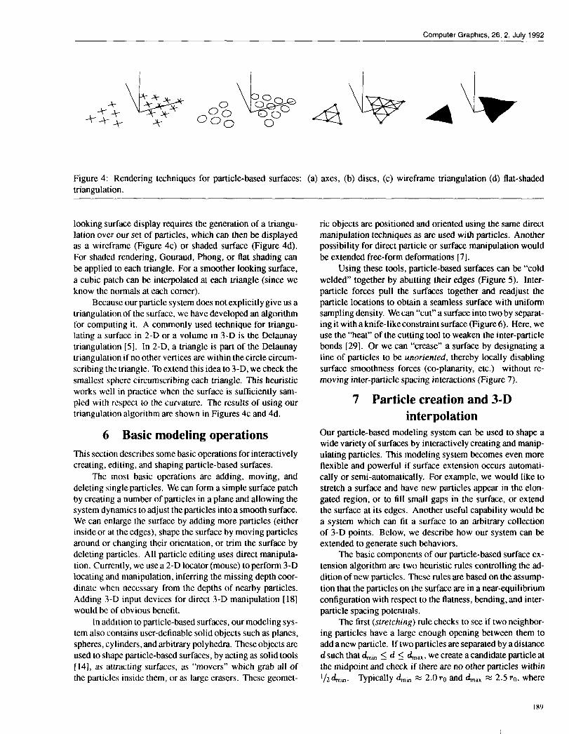
Figure 4: Rendering techniques for particle-based surfaces: (a) axes, (b) discs, (c) wireframe triangulation (d) flat-shaded
triangulation.
looking surface display requires the generation of a triangu-lation over our set of particles, which can then be displayedas a wireframe (Figure 4c) or shaded surface (Figure 4d).For shaded rendering, Gouraud, Phong, or flat shading can
be applied to each triangle. For a smoother looking surface,
a cubic patch can be interpolated at each triangle (since weknow the normals at each comer).
Because our particle system does not explicitly give us a
triangulation of the surface, we have developed an algorithmfor computing it. A commonly used technique for triangu-lating a surface in 2-D or a volume in 3-D is the Delaunay
triangulation [5]. In 2-D, a triangle is part of the Delaunaytriangulation if no other vertices are within the circle circum-scribing the triarrglc. To extend this idea to 3-D, we check the
smallest sphere circumscribing each triangle. This heuristicworks well in practice when the surface is sufficiently sam-pled with respect to the curvature. The results of using ourtriangulation algorithm arc shown in Figures 4C and 4d.
6 Basic modeling operationsThis section describes some basic operations for interactively
creating, editing, and shaping particle-based surfaces.
The most basic operations are adding, moving, and
deleting single particles. We can forma simple surface patchby creating a number of particles in a plane and allowing thesystem dynamics to adjust the particles into a smooth surface.We can enlarge the surface by adding more particles (eitherinside or at the edges), shape the surface by moving particles
around or changing their orientation, or trim the surface bydeleting particles. All particle editing uses direct manipula-
tion. Currently, we use a 2-D locator (mouse) to perform 3-Dlocating and manipulation, inferring the missing depth coor-
dinate when necessary from the depths of nearby particles.Adding 3-D input devices for direct 3-D manipulation [18]
would bc of obvious benefit.
In addition to particle-based surfaces, our modeling sys-tem also contains user-definable solid objects such as planes,
spheres, cylinders, and arbitrary polyhedra. These objects areused to shape particle-based surfaces, by acting as solid tools[14], as attracting surfaces, as “movers” which grab all of
the particles inside them, or as large erasers. These geomet-
ric objects are positioned and oriented using the same directmanipulation techniques as are used with particles. Anotherpossibility for direct particle or surface manipulation would
be extended free-form deformations [7].
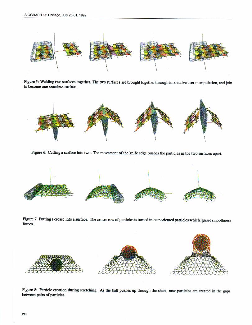
Using these tools, particle-based surfaces can be “coldwelded” together by abutting their edges (Figure 5). Inter-
particle forces pull the surfaces together and readjust theparticle locations to obtain a seamless surface with uniformsampling density. We can “cut” a surface into two by separat-ing it with a knife-like constraint surface (Figure 6). Here, weuse the “heat” of the cutting tool to weaken the inter-particlebonds [29]. Or we can “crease” a surface by designating aline of particles to be unorien[ed, thereby locally disablingsurface smoothness forces (co-phmarit y, etc.) without re-
moving inter-particle spacing interactions (Figure 7).
7 Particle creation and 3-Dinterpolation
Our particle-based modeling system can be used to shape awide variety of surfaces by interactively creating and manip-ulating particles. This modeling system becomes even moreflexible and powerful if surface extension occurs automati-
cally or semi-automatically. For example, we would like tostretch a surface and have new particles appear in the elon-gated region, or to till small gaps in the surface, or extendthe surface at its edges. Another useful capability would bea system which can fit a surface to an arbitrary collectionof 3-D points. Below, we describe how our system can beextended to generate such behaviors.
The basic components of our particle-based surface ex-
tension algorithm are two heuristic rules controlling the ad-dition of new particles. These rules are based on the assump-
tion that the particles on the surface are in a near-equilibriumconfiguration with respect to the flatness, bending, and inter-particle spacing potentials.
The first (stretching) rule checks to see if two neighbor-ing particles have a large enough opening between them toadd anew particle. If lwo particles are separated by a distanced such that +~ ~ d g &,X, we create a candidate particle at
the midpoint and check if there are no other particles within
l/zo&~. Vpically Lm = 2.0 TO and A.. x 2.5 TO, where
189
SIGGRAPH ‘92 Chicago, July 26-31, 1992
Figure 5: Welding two surfaces together. The two surfaces are brought together through interactive user manipulation, and join to become one seamless surface.
Figure 6: Cutting a surface into two. The movement of the knife edge pushes the particles in the two surfaces apart.
- -
L ‘:
.
Figure 7: Putting a crease into a surface. The center row of particles is turned into unoriented particles which ignore smoothness
forces.
Figure 8: Particle creation during stretching. As the ball pushes up through the sheet, new particles are created in the gaps between pairs of particles.
190
Computer Graphics, 26, 2, .IuIY1992
r. is the natural inter-particle spacing. An exampleof thisstretchingrule in action is shown in Figure 8, where a ballpushing against a sheet stretches it to the point where newparticles are added.
The second (growing) rule allows particles to be addedin all directions with respect to a particle’s local z-y plane.The rule is generalized to allow a minimum and maximumnumber of neighbors and to limit growth in regions of few
neighboring particles, such as at the edge of a surface. The
rule counts the number of immediate neighbors n~ to seeif it falls within a valid range ~~ ~ rtN < ~~X, It also
computes the angles between successive neighbors AO~ =
~i+l – Oa using the particle’s locat coordinate frame, andchecks if these fall within a suitable range 6~ti ~ A6a s &,X.If these conditions are met, one or more particles are createdin the gap. In generat, a sheet at equilibrium will have interior
particles with six neighbors spaced 60° apart while edgeparticles will have four neighbors with one pair of neighbors
180° apart.
With these two rules, we can automatically build a sur-face from collections of 3-D points. We create particles ateach sample location and fix their positions and orientations.We then start filling in gaps by growing particles away fromisolated points and edges, After a rough surface approxima-tion is complete we can release the originat sampled particles
to smooth the final surface thereby eliminating excessivenoise. If the set of data points is reasonably distributed, this
approach will result in a smooth continuous closed surface(Figure 9). The fitted surface is not limited to a particular
topology, unlike previous 3-D surface fitting models such as[25, 13].
We can also fit surfaces to data that does not originatefrom closed surfaces, such as stereo range data [9, 22]. Sim-ply growing particles away from the sample points poses
several problems. For example, if we allow growth in alldirections, the surface may grow indefinitely at the edges,whereas if we limit the growth at edges, we may not be ableto fill in certain gaps. Instead, we apply the stretching heuris-tic to effectively interpolate the surface between the samplepoints (Figure 10). When the surface being reconstructed hasholes or gaps, we can control the size of gaps that are filledin by limiting the search range. This is evident in Figure10, where the cheek and neck regions have few samples andwere therefore not reconstructed. We could have easily filledin these regions by using a larger search range.
8 Geometric Modeling Applications
The particle-based surface models we have presented can beused in a wide range of geometric modeling and animationapplications. These include applications which have beenpreviously demonstrated with physically-based deformable
surface models, such as cloth draping [30, 25, 6], plastic
surface deformations [24], and tearing [24].
Using our surface model as an interactive design toolwe can spray collections of points into space to form elastic
sheets, shape them under interactive user control, and thenfreeze them into the desired final configuration. We can cre-
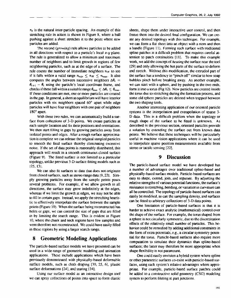
ate any desired topology with this technique. For example,we can form a flat sheet into an object with a stem and thena handle (Figure 11). Forming such surface with traditional
spline patches is a difficult problem that requires careful at-tention to patch continuities [11]. To make this example
work, we add the concept of heating the surface near the tool[29] and only allowing the hot parts of the surface to deform
and stretch. Without this modification, the extruded part of
the surface has a tendency to “pinch off” similar to how soapbubbles pinch before breaking away. As another example,we can start with a sphere, and by pushing in the two ends,form it into a torus (Fig 12). New particles are created insidethe torus due to stretching during the formation process, andsome old sphere particles are deleted when trapped betweenthe two shaping tools.
Another interesting application of our oriented particle
systems is the interpolation and extrapolation of sparse 3-D data. This is a difficult problem when the topology orrough shape of the surface to be fitted is unknown. Asdescribed in the previous section, oriented particles providea solution by extending the surface out from known datapoints. We believe that these techniques will be particularlyuseful in machine vision applications where it can be used
to interpolate sparse position measurements available fromstereo or tactile sensing [22],
9 Discussion
The particle-based surface model we have developed hasa number of advantages over traditional spline-based andphysically-based surface models. Particle-based surfaces areeasy to shape, extend, join, and separate. By adjusting therelative strengths of various potential functions, the surface’sresistance to stretching, bending, or variation in curvature can
atl be controlled. The topology of particle-based surfaces caneasily be modified, as can the sampling density, and surfacescan be fitted to arbitrary collections of 3-D data points.
One limitation of particle-based surfaces is that it isharder to achieve exact anatytic (mathematical) control overthe shape of the surface. For example, the torus shaped from
a sphere is not circularly symmetric, due to the discretizationeffects of the relatively small number of particles. This be-haviorcould be remedied by adding additional constraints in
the form of extra potentials, e.g., a circular symmetry poten-
tial for the torus. Particle-based surfaces also require morecomputation to simulate their dynamics than spline-basedsurfaces; the latter may therefore be more appropriate whenshape flexibility is not paramount.
One could easily envision a hybrid system where splineor other parametric surfaces co-exist with particle-based sur-faces, using each system’s relative advantages where appro-priate. For example, particle-based surface patches could
be added to a constructive solid geometry (CSG) modeling
system to perform fileting at part junctions.
191
SIGGRAPH ‘92 Chicago, July 26-31, 1992
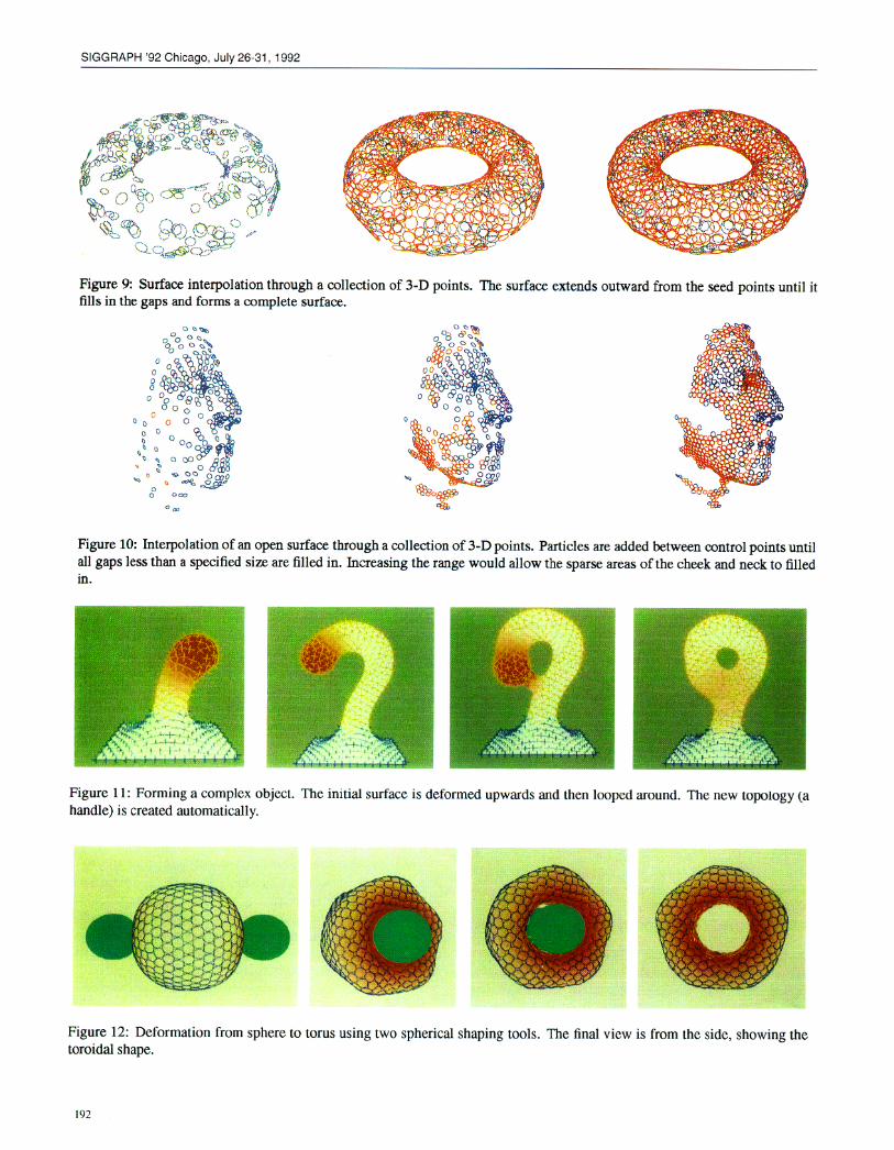
Figure 9: Surface interpolation through a collection of 3-D points. The surface extends outward from the seed points until it fills in the gaps and forms a complete surface.
Figure 10: Interpolation of an open surface through a collection of 3-D points. Particles are added between control points until all gaps less than a specified size are filled in. Increasing the range would allow the suarse areas of the cheek and neck to filled
L
Figure 11: Forming a complex object. The initial surface is deformed upwards and then looped around. The new topology (a handle) is created automatically.
Figure 12: Deformation from sphere to toroidal shape.
torus using two spherical shaping tools. The final view is from the side, showing the
Computer Graphics, 26,2, July 1992
In future work, we plan to apply particle-based surfaces
to iso-surfaces in volumetric data sets. When combined withthe stretching heuristic for particle creation and an inflationforce, this model would behave in a manner similar to thegeometrically deformed models (GDM) of [13]. We couldextend this idea by tracking a volumetric data set through
time by deforming the particle surface from one frame to thenext.
In another application, we could distribute the particles
over the surface of a CAD model and allow the particles tochange position and orientation while remaining on the sur-face of the model, thereby creating a uniform triangulation ofthe surface. Figure 10 shows how this can be achieved, evenwithout the presence of the CAD model surface to attract the
particles. A curvature-dependent adaptive meshing of the
surface could also be obtained by locally adjusting the pre-ferred inter-particle spacing. This would be very useful for
efficiently rendering parametric surfaces such as NURBS.
10 ConclusionIn this paper, we have developed a particle-based model ofdeformable surfaces. Our new model, which is based onoriented particles with new interaction potentials, has char-acteristics of both physically-based surface models and ofparticle systems. It can be used to model smooth, elastic,moldable surfaces, like traditional splines, and it allows for
arbitrary interactions and topologies, like particle systems.A potential drawback of our technique is the lack of precisecontrol over the mathematical form of the surface, which maybe important in engineering applications.
Like previous deformable surface models, our newparticle-based surfaces can simulate cloth, elastic and plasticfilms, and other deformable surfaces. The ability to grow newparticles gives these model more fluid-like properties whichextend the range of interactions. For example, the surfacescan be joined and cut at arbitrary locations. These charac-teristics make particle-based surfaces a powerful new toolfor the interactive construction and modeling of free-formsurfaces.
Oriented particles can also be used to automatically fita surface to sparse 3-D data even when the topology of thesurface is unknown. Both open and closed surfaces can be re-constructed, either with or without holes. The reconstructedmodel can be used as the starting point to interactively createanew shape and then animated within a virtual environment.Thus oriented particle systems providea convenient interface
between surface reconstruction in computer vision, freeformmodeling in computer graphics, and animation.
References[1]
[2]
Appel, Andrew. An Efficient Algorithm for Many-bodySimulations. SIAM J. Sci. Stat. Comput., 6(l), 1985.
Bartels, Richard. H. and Beatty, John. C. A Techniquefor the Direct Manipulation of SplineCurves. In Graph-ics Interface ’89, pages 33–39, June 1989.
[3]
[4]
[5]
[6]
[7]
[8]
[9]
[10]
[11]
[12]
[13]
[14]
[15]
Bartels, Richard. H., Beatty, John. C., and Barsky,Brian. A. An introduction 10Splinesfor use in ComputerGraphics and Geometric Modeling. Morgan Kauf-mann Publishers, Los Altos, California, 1987.
Blinn, James F. A Generalization of Algebraic SurfaceDrawing. ACM Transactions on Graphics, 1(3):235-256, July 1982.
Boissonat, J.-D, Representing 2D and 3D Shapes with
the Ddaunay Triangulation. In Seventh InternationalConference on Pauern Recognition (ICPR’84), pages745–748, Montreal, Canada, July 1984.
Breen, David E., House, Donald H., and Getto,Phillip H. A Particle-Based Computational Model ofCloth Draping Behavior. In Patrikalakis, N. M., editor,
Scientijlc Visualization of Physical Phenomena, pages113–1 34. Springer-Verlag, New York, 1991.
Coquillart, Sabine. Extended Free-Form Deformations:A Sculpturing Tool for 3D Geometric Modeling. Com-puter Graphics (SIGGRAPH 90), 24(4):187-196, Au-gust 1990.
Farin, Gerald. E. Curves and Surfaces for ComputerAided Geometric Design: A Practical Guide. AcademicPress, Boston, Massachusetts, 2nd edition, 1990.
Fua, Pascat and Sander, Peter. Reconstructing Sur-
faces from Unstructured 3D Points. In Second Euro-
pean Conference on Computer Vision (ECCV’ 92), Sta.Margherita, Italy, May 1992. Springer-Verlag.
Hockney, Roger W. and Eastwood, James W. ComputerSimulation using Particles. McGraw-Hill Inc., NewYork, 1988.
Loop, Charles and DeRose, Tony. Generalized B-spline
Surfaces of Arbitrary Topology. Computer Graphics(S[GGRAPH’90), 24(4):347-356, August 1990.
Miller, Gavin and Pearce, Andrew. Globular Dynamics:A Conntxted Particle System for Animating VkcousFluids. In SIGGRAPH ’89, Course 30 noles: Topicsin Physically-based Modeling, pages R 1- R23. SIG-GRAPH, August 1989. Boston, Massachusetts.
Miller, James V., Brcxm, David E., Lorensen,
William E., O’Bara, Robert M., and Wozny, Michael J.
Geometrically Deformed Models: A Method of Ex-
tracting Closed Geometric Models from Volume Data.Computer Graphics (SIGGRAPH91), 25(4):217-226,July 1991.
Platt, John C. and Barr, Alan H. Constraint Meth-
ods for Flexible Models. Computer Graphics (SIG-GRAPH’88), 22(4):279-288, August 1988.
Press, William H., Flannery, Brian P., Teukolsky,
Saul A., and Vetteding, William T. Numerical Recipesin C: The Art of Scientific Compuling. Cambridge Uni-versity Press, Cambridge, England, 1988.
I93
SIGGRAPH ’92 Chicago, July 26-31, 1992
[16]
[17]
[18]
[19]
[20]
[21]
[22]
[23]
[24]
[25]
[26]
[27]
[28]
[29]
I94
Reeves, William. T. Particle Systems—A Technique forModeling a Class of Fuzzy Objects. ACM Transactionsof Graphics, 2(2):9 1–108, April 1983.
Reynolds, Craig. W. Ftocks, Herds, and Schools: A
Distributed Behavioral Model. Compuler Graphics(SIGGRAPH87), 21(4):25-34, hlly 1987.
Sachs, Emanuel, Roberts, Andrew, and Stoops, David.3-Draw: A Tool for Designing 3D Shapes. IEEE Com-puter Graphics & Applications, 11(6): 18–26, Novem-ber 1991.
Samet, Hanan. The Design andAnalysis of SpalialDataStructures. Addison-Wesley, Reading, Massachusetts,1989.
Shoemake, Ken. Animating Rotation with Quater-nion Curves. Computer Graphics (SIGGRAPH85),19(3):245-2540, July 1985.
Sims, Karl. Particle Animation and Rendering UsingData Parallel Computation. Computer Graphics (SIG-
GRAPH90), 24(4):405+13, August 1990.
Szeliski, Richard. Shape from Rotation. In IEEE Com-puter Society Conference on Computer Vision and Pat-tern Recognition (CVPR’91), pages 625-630, Maui,Hawaii, June 1991. IEEE Computer Society Press.
Szeliski, Richmd and Tonnesen, David. Surface Mod-eling with Oriented Particle Systems. Technical Report91/14, Digitat Equipment Corporation, Cambridge Re-search Lab, December 1991.
Terzopoulos, Demetri and Fleischer, Kurt. Modeling
Inelastic Deformations: Visoelasticity, Plasticity, Frac-ture. Computer Graphics (SIGGRAPH’88), 22(4):269–278, August 1988.
Terzopmdos, Demetri, Platt, John, Barr, Alan, andFleischer, Kurt. Elastically deformable models. Com-
puter Graphics (S1GGRAPH87), 21(4):205-214, July1987.
Terzopoulos, Demetri, Platt, John, and Fleischer, Kurt.From Goop to Glop: Heating and Melting DeformableModels. In Proceedings Graphics Inte~ace, pages 219-226. Graphics Interface, June 1989.
Terzopoulos, Demetri, Witkin, Andrew, and Kass,Michael. Symmetry-S&king Models and 3D ObjectReconstruction. International Journal of Computer Vi-sion, 1(3):21 l–221,0ctober 1987.
Tonnesen, David. Ray-tracing Implicit Surfaces Re-
sulting from the Summation of Bounded PolynomialFunctions. Technical Report TR-89003, Rensselaer De-
sign Research Center, Rensselaer Polytechnic Institute,Troy, New York, 1989.
Tonnesen, David. Modeling Liquids and Solids using
Thermal Particles. In Graphics [nterface ‘91, pages255-262, 1991.
[30] Weil, Jerry. The Synthesis of Cloth Objects. ComputerGraphics (SIGGRAPH’86), 20(4):49–54, August 1986.
A Computation of internal forcesTo compute the internal inter-particle forces and torques, we
compute the variation of inter-particle potentials with respectto particle positions and orientations. We can compute theseforces and torques using the equations
f = –VP~ and Vp(p. v) = vr= –VW~ and Vw(n. v)=nxv
where u is the incremental change in orientation R, i.e.,lianxw.
Applying these equations to the four internal potentials,we obtain
f~(r~j) n ‘fiij &(llrijll)
fp(I’ii, r;j) = –lli(ni “rij)+(llrijll)
- ~ij(rli . rij)2 %$ ’(llrijll)
~P(ni, rij) = rij x ni(ni “rij)~(llrijll) = rij x fp
fN(Ilijlljjrij) = ‘fiijllni - njllz%$’(llrijll)
‘N(ni~nj, rij) = ‘i x ‘j ~(llrij[l)
fi(nilnj>rij) = ‘ni((ni + nj) “ rij)d(llrijll)
– Fij((lli + nj) .rij)z@’(llrijll)
~c(nitnj, rij) = rij X fc
where tij is the unit vtxtor along rij. These forces have thefollowing simple physical interpretations.
The co-planarity potential gives rise to a force parallel tothe particle normat and proportional to the distance betweenthe neighboring particle and the local tangent plane. Thesecond term in the force, which can often be ignored, arisesfrom the gradient of the spatial weighting function. The crossproduct of this force with the inter-particle vector produces a
torque on the particle. The co-normality potential produces
a torque proportional to the cross-product of the two particlenormrds, which acts to Iign up the normals. The co-circularityforce is similar to the co-planarity force, except that the local
tangent plane is defined from the average of the two normalvectors.
To compute the total inter-particle force and torque fromatl three potentials, we use the formulas
fa = ~ 2~~f~(rij) + ~p(fp(ni, rij) – fp(nj, rji))
j~tii
+ 2~NfP(Ili, Ilj, rij) + 2~cf&(ni, nj} rij)
‘i= ~ adni,rij)jEN;
+ 2~N~p(ni, nj, rij ) + 2W~c(ni, nj, rij)