Embed Size (px)
Citation preview
© KEMET Electronics Corporation • P.O. Box 5928 • Greenville, SC 29606 (864) 963-6300 • www.kemet.com F3082_LDB • 7/31/2014 1One world. One KEMET
Benefits
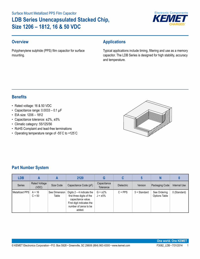
• Rated voltage: 16 & 50 VDC• Capacitance range: 0.0033 – 0.1 µF• EIA size: 1206 – 1812• Capacitance tolerance: ±2%, ±5%• Climatic category: 55/125/56• RoHS Complaint and lead-free terminations• Operatingtemperaturerangeof-55˚Cto+125˚C
Overview
Polyphenylenesulphide(PPS)filmcapacitorforsurfacemounting.
Applications
Typicalapplicationsincludetiming,filteringanduseasamemorycapacitor. The LDB Series is designed for high stability, accuracy and temperature.
Surface Mount Metallized PPS Film Capacitor
LDB Series Unencapsulated Stacked Chip, Size 1206 – 1812, 16 & 50 VDC
Part Number System
LDB A A 2120 G C 5 N 0
Series Rated Voltage (VDC) Size Code Capacitance Code (pF) Capacitance
Tolerance Dielectric Version Packaging Code Internal Use
Metallized PPS A = 16 C = 50
See Dimension Table
Digits 2 – 4 indicate the firstthreedigitsofthe
capacitance value. First digit indicates the number of zeros to be
added.
G = ±2% J = ±5%
C = PPS 5 = Standard See Ordering Options Table
0 (Standard)
© KEMET Electronics Corporation • P.O. Box 5928 • Greenville, SC 29606 (864) 963-6300 • www.kemet.com F3082_LDB • 7/31/2014 2
Surface Mount Metallized PPS Film Capacitors LDB Series Unencapsulated Stacked Chip, Size 1206 – 1812, 16 & 50 VDC
Ordering Options Table
Packaging Type Packaging Code
Standard Packaging OptionsTape & Reel (Standard Reel) N
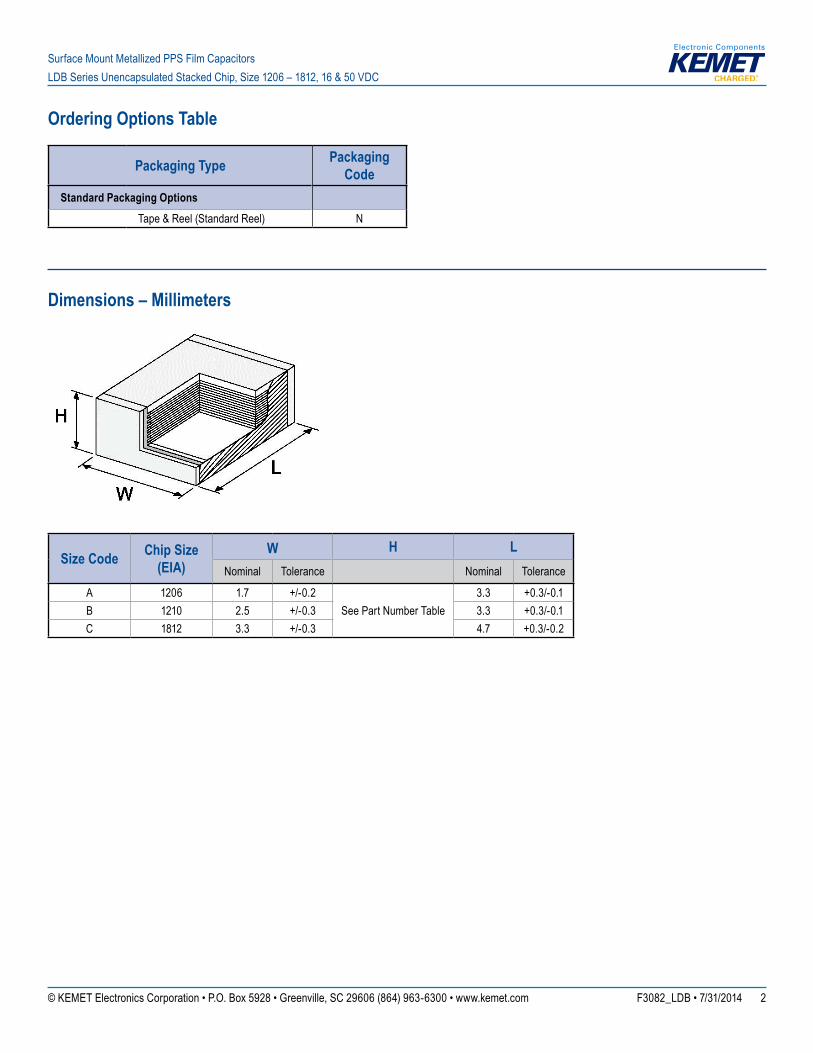
Dimensions – Millimeters
Size Code Chip Size (EIA)
W H LNominal Tolerance Nominal Tolerance
A 1206 1.7 +/-0.2See Part Number Table
3.3 +0.3/-0.1B 1210 2.5 +/-0.3 3.3 +0.3/-0.1C 1812 3.3 +/-0.3 4.7 +0.3/-0.2
© KEMET Electronics Corporation • P.O. Box 5928 • Greenville, SC 29606 (864) 963-6300 • www.kemet.com F3082_LDB • 7/31/2014 3
Surface Mount Metallized PPS Film Capacitors LDB Series Unencapsulated Stacked Chip, Size 1206 – 1812, 16 & 50 VDC
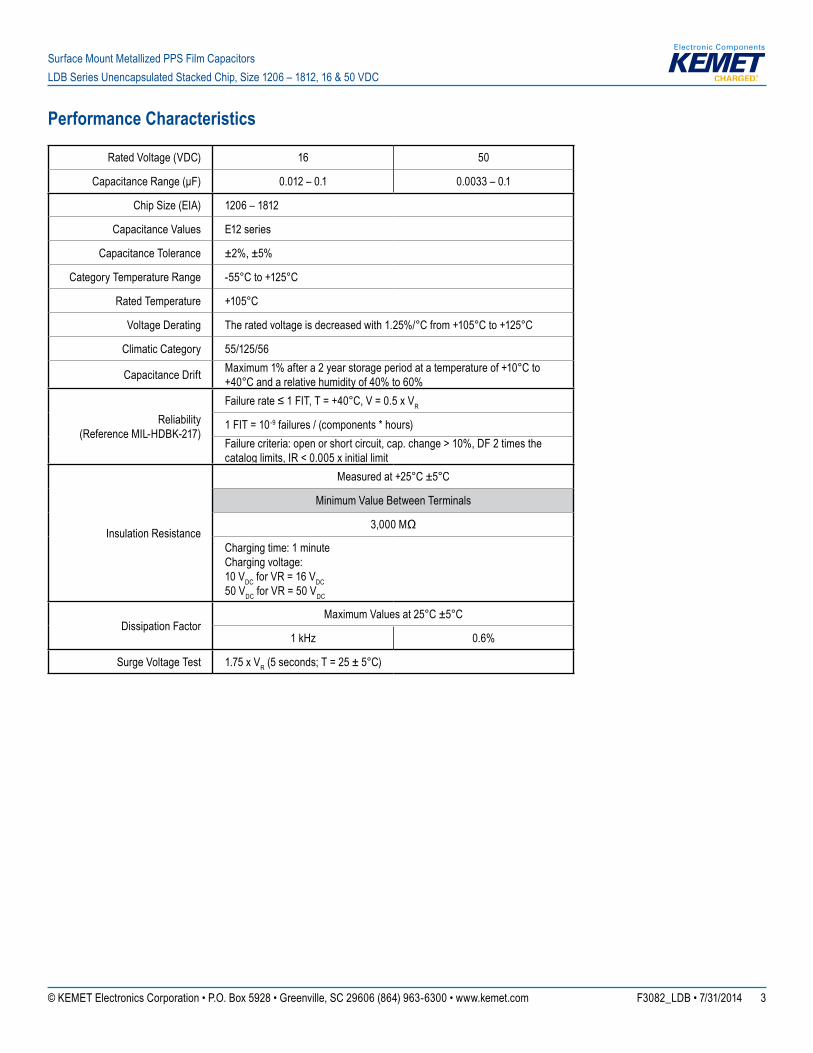
Performance Characteristics
Rated Voltage (VDC) 16 50
CapacitanceRange(μF) 0.012 – 0.1 0.0033 – 0.1
Chip Size (EIA) 1206 – 1812
Capacitance Values E12 series
Capacitance Tolerance ±2%, ±5%
Category Temperature Range -55°Cto+125°C
Rated Temperature +105°C
Voltage Derating Theratedvoltageisdecreasedwith1.25%/°Cfrom+105°Cto+125°C
Climatic Category 55/125/56
Capacitance Drift Maximum1%aftera2yearstorageperiodatatemperatureof+10°Cto+40°Candarelativehumidityof40%to60%
Reliability(Reference MIL-HDBK-217)
Failurerate≤1FIT,T=+40°C,V=0.5xVR
1 FIT = 10-9 failures / (components * hours)Failure criteria: open or short circuit, cap. change > 10%, DF 2 times the catalog limits, IR < 0.005 x initial limit
Insulation Resistance
Measuredat+25°C±5°C
Minimum Value Between Terminals
3,000MΩ
Charging time: 1 minuteCharging voltage:10 VDC for VR = 16 VDC50 VDC for VR = 50 VDC
Dissipation FactorMaximum Values at 25°C ±5°C
1 kHz 0.6%
Surge Voltage Test 1.75 x VR (5 seconds; T = 25 ± 5°C)
© KEMET Electronics Corporation • P.O. Box 5928 • Greenville, SC 29606 (864) 963-6300 • www.kemet.com F3082_LDB • 7/31/2014 4
Surface Mount Metallized PPS Film Capacitors LDB Series Unencapsulated Stacked Chip, Size 1206 – 1812, 16 & 50 VDC
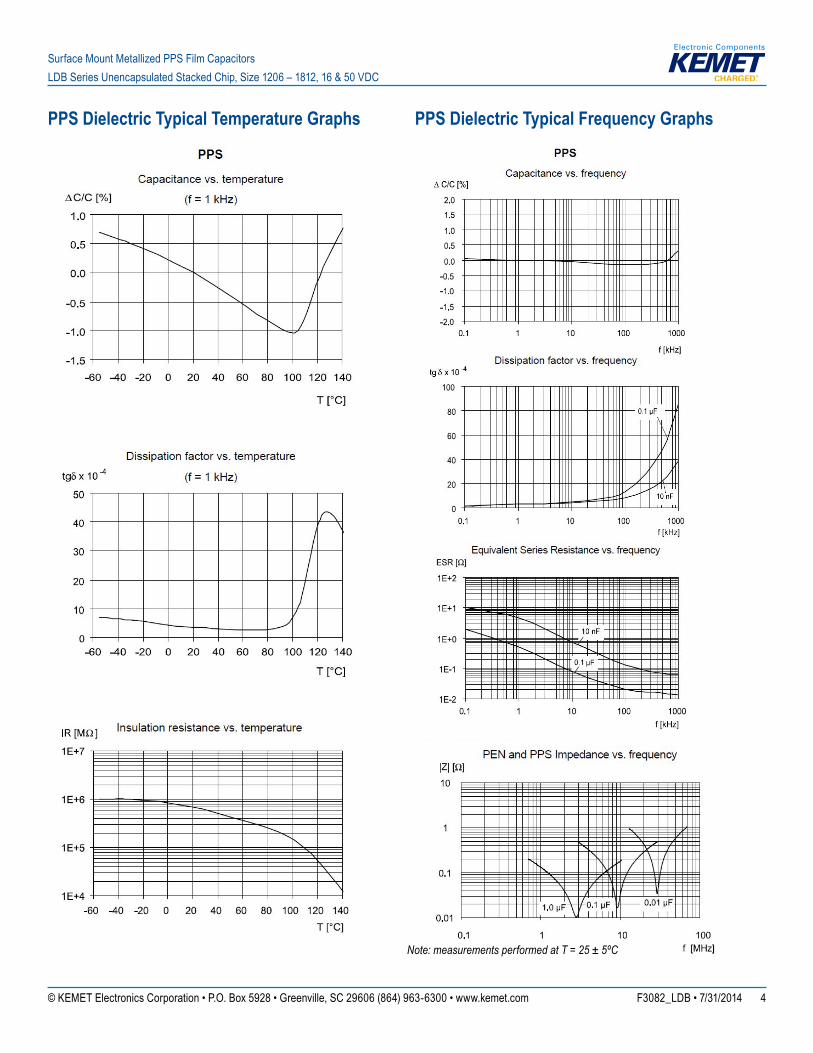
PPS Dielectric Typical Temperature Graphs PPS Dielectric Typical Frequency Graphs
Note: measurements performed at T = 25 ± 5ºC
© KEMET Electronics Corporation • P.O. Box 5928 • Greenville, SC 29606 (864) 963-6300 • www.kemet.com F3082_LDB • 7/31/2014 5
Surface Mount Metallized PPS Film Capacitors LDB Series Unencapsulated Stacked Chip, Size 1206 – 1812, 16 & 50 VDC
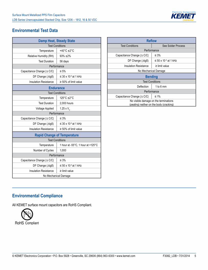
Environmental Test Data
Damp Heat, Steady StateTest Conditions
Temperature +40°C±2°CRelative Humidity (RH) 93% ±2%
Test Duration 56 daysPerformance
CapacitanceChange|∆C/C| ≤5%DFChange(∆tgδ) ≤30x10-4 at 1 kHz
Insulation Resistance ≥50%oflimitvalue
EnduranceTest Conditions
Temperature 125°C ±2°CTest Duration 2,000 hours
Voltage Applied 1.25 x VC
PerformanceCapacitanceChange|∆C/C| ≤3%
DFChange(∆tgδ) ≤30x10-4 at 1 kHzInsulation Resistance ≥50%oflimitvalue
Rapid Change of TemperatureTest Conditions
Temperature 1hourat-55°C,1hourat+125°CNumber of Cycles 1,000
PerformanceCapacitanceChange|∆C/C| ≤3%
DFChange(∆tgδ) ≤50x10-4 at 1 kHzInsulation Resistance ≥limitvalue
No Mechanical Damage
ReflowTest Conditions See Solder Process
PerformanceCapacitanceChange|∆C/C| ≤3%
DFChange(∆tgδ) ≤50x10-4 at 1 kHzInsulation Resistance ≥limitvalue
No Mechanical Damage
BendingTest Conditions
Deflection 1 to 6 mmPerformance
CapacitanceChange|∆C/C| ≤1%No visible damage on the terminations (pealing) neither on the body (cracking)
Environmental Compliance
All KEMET surface mount capacitors are RoHS Compliant.
© KEMET Electronics Corporation • P.O. Box 5928 • Greenville, SC 29606 (864) 963-6300 • www.kemet.com F3082_LDB • 7/31/2014 6
Surface Mount Metallized PPS Film Capacitors LDB Series Unencapsulated Stacked Chip, Size 1206 – 1812, 16 & 50 VDC
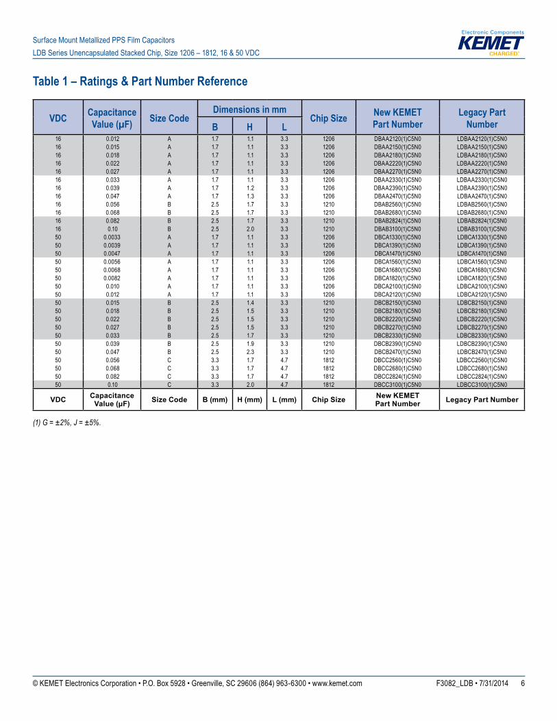
Table 1 – Ratings & Part Number Reference
VDC Capacitance Value (µF) Size Code
Dimensions in mmChip Size New KEMET
Part NumberLegacy Part
NumberB H L16 0.012 A 1.7 1.1 3.3 1206 DBAA2120(1)C5N0 LDBAA2120(1)C5N016 0.015 A 1.7 1.1 3.3 1206 DBAA2150(1)C5N0 LDBAA2150(1)C5N016 0.018 A 1.7 1.1 3.3 1206 DBAA2180(1)C5N0 LDBAA2180(1)C5N016 0.022 A 1.7 1.1 3.3 1206 DBAA2220(1)C5N0 LDBAA2220(1)C5N016 0.027 A 1.7 1.1 3.3 1206 DBAA2270(1)C5N0 LDBAA2270(1)C5N016 0.033 A 1.7 1.1 3.3 1206 DBAA2330(1)C5N0 LDBAA2330(1)C5N016 0.039 A 1.7 1.2 3.3 1206 DBAA2390(1)C5N0 LDBAA2390(1)C5N016 0.047 A 1.7 1.3 3.3 1206 DBAA2470(1)C5N0 LDBAA2470(1)C5N016 0.056 B 2.5 1.7 3.3 1210 DBAB2560(1)C5N0 LDBAB2560(1)C5N016 0.068 B 2.5 1.7 3.3 1210 DBAB2680(1)C5N0 LDBAB2680(1)C5N016 0.082 B 2.5 1.7 3.3 1210 DBAB2824(1)C5N0 LDBAB2824(1)C5N016 0.10 B 2.5 2.0 3.3 1210 DBAB3100(1)C5N0 LDBAB3100(1)C5N050 0.0033 A 1.7 1.1 3.3 1206 DBCA1330(1)C5N0 LDBCA1330(1)C5N050 0.0039 A 1.7 1.1 3.3 1206 DBCA1390(1)C5N0 LDBCA1390(1)C5N050 0.0047 A 1.7 1.1 3.3 1206 DBCA1470(1)C5N0 LDBCA1470(1)C5N050 0.0056 A 1.7 1.1 3.3 1206 DBCA1560(1)C5N0 LDBCA1560(1)C5N050 0.0068 A 1.7 1.1 3.3 1206 DBCA1680(1)C5N0 LDBCA1680(1)C5N050 0.0082 A 1.7 1.1 3.3 1206 DBCA1820(1)C5N0 LDBCA1820(1)C5N050 0.010 A 1.7 1.1 3.3 1206 DBCA2100(1)C5N0 LDBCA2100(1)C5N050 0.012 A 1.7 1.1 3.3 1206 DBCA2120(1)C5N0 LDBCA2120(1)C5N050 0.015 B 2.5 1.4 3.3 1210 DBCB2150(1)C5N0 LDBCB2150(1)C5N050 0.018 B 2.5 1.5 3.3 1210 DBCB2180(1)C5N0 LDBCB2180(1)C5N050 0.022 B 2.5 1.5 3.3 1210 DBCB2220(1)C5N0 LDBCB2220(1)C5N050 0.027 B 2.5 1.5 3.3 1210 DBCB2270(1)C5N0 LDBCB2270(1)C5N050 0.033 B 2.5 1.7 3.3 1210 DBCB2330(1)C5N0 LDBCB2330(1)C5N050 0.039 B 2.5 1.9 3.3 1210 DBCB2390(1)C5N0 LDBCB2390(1)C5N050 0.047 B 2.5 2.3 3.3 1210 DBCB2470(1)C5N0 LDBCB2470(1)C5N050 0.056 C 3.3 1.7 4.7 1812 DBCC2560(1)C5N0 LDBCC2560(1)C5N050 0.068 C 3.3 1.7 4.7 1812 DBCC2680(1)C5N0 LDBCC2680(1)C5N050 0.082 C 3.3 1.7 4.7 1812 DBCC2824(1)C5N0 LDBCC2824(1)C5N050 0.10 C 3.3 2.0 4.7 1812 DBCC3100(1)C5N0 LDBCC3100(1)C5N0
VDC Capacitance Value (µF) Size Code B (mm) H (mm) L (mm) Chip Size New KEMET
Part Number Legacy Part Number
(1) G = ±2%, J = ±5%.
© KEMET Electronics Corporation • P.O. Box 5928 • Greenville, SC 29606 (864) 963-6300 • www.kemet.com F3082_LDB • 7/31/2014 7
Surface Mount Metallized PPS Film Capacitors LDB Series Unencapsulated Stacked Chip, Size 1206 – 1812, 16 & 50 VDC
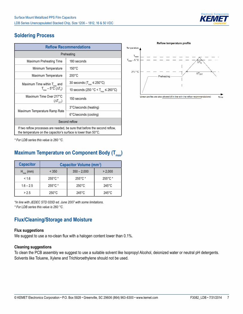
Soldering Process
Reflow RecommendationsPreheating
Maximum Preheating Time 180 seconds
Minimum Temperature 150°C
Maximum Temperature 200°C
Maximum Time within Tmax and Tmax–5°C(∆T5)
30 seconds (Tmax≤250°C)
10 seconds (250 °C < Tmax≤260°C)
Maximum Time Over 217°C (∆T217)
150 seconds
Maximum Temperature Ramp Rate3°C/seconds (heating)
6°C/seconds (cooling)
Secondreflow
Iftworeflowprocessesareneeded,besurethatbeforethesecondreflow,the temperature on the capacitor’s surface is lower than 50°C.
* For LDB series this value is 260 °C.
Maximum Temperature on Component Body (Tmax)
Capacitor Capacitor Volume (mm3)Hmax (mm) < 350 350 – 2,000 > 2,000
< 1.6 255°C * 255°C * 255°C *
1.6 – 2.5 255°C * 250°C 245°C
> 2.5 250°C 245°C 245°C
*In line with JEDEC STD 020D ed. June 2007 with some limitations.* For LDB series this value is 260 °C.
Flux/Cleaning/Storage and Moisture
Flux suggestionsWesuggesttouseano-cleanfluxwithahalogencontentlowerthan0.1%.
Cleaning suggestionsTo clean the PCB assembly we suggest to use a suitable solvent like Isopropyl Alcohol, deionized water or neutral pH detergents. Solvents like Toluene, Xylene and Trichloroethylene should not be used.
© KEMET Electronics Corporation • P.O. Box 5928 • Greenville, SC 29606 (864) 963-6300 • www.kemet.com F3082_LDB • 7/31/2014 8
Surface Mount Metallized PPS Film Capacitors LDB Series Unencapsulated Stacked Chip, Size 1206 – 1812, 16 & 50 VDC
Flux/Cleaning/Storage and Moisture cont'd
Storage and moisture recommendationsKEMET SMD Film Capacitors are supplied in a MBB (Moisture Barrier Bag) Class 1. We can guarantee a 24 months shelf life (temperature≤40°C/relativehumidity≤90%).AftertheMBBhasbeenopened,componentsmaystayinareaswithcontrolledtemperatureandhumidity(temperature≤30°C/relativehumidity≤60%)for168hours(ratedvoltage≤100VDC)or696hours(ratedvoltage > 100 VDC). For longer periods of time and/or higher temperature and/or higher relative humidity values, it is absolutely necessary to protect the components against humidity. If the reel inside the MBB is partially used, KEMET recommends to re-use the same MBB or to avoid areas without controlled temperature and humidity (see above). If the above conditions are not respected, componentsrequireabaking(minimumtime:48hoursat55±5°C)beforethereflow.
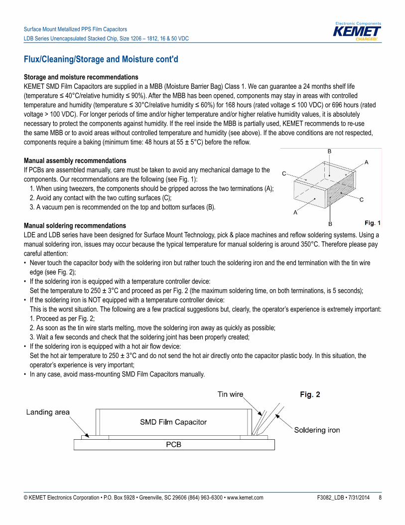
Manual assembly recommendationsIf PCBs are assembled manually, care must be taken to avoid any mechanical damage to the components. Our recommendations are the following (see Fig. 1): 1. When using tweezers, the components should be gripped across the two terminations (A); 2. Avoid any contact with the two cutting surfaces (C); 3. A vacuum pen is recommended on the top and bottom surfaces (B).
Manual soldering recommendationsLDEandLDBserieshavebeendesignedforSurfaceMountTechnology,pick&placemachinesandreflowsolderingsystems.Usingamanual soldering iron, issues may occur because the typical temperature for manual soldering is around 350°C. Therefore please pay careful attention:• Never touch the capacitor body with the soldering iron but rather touch the soldering iron and the end termination with the tin wire
edge (see Fig. 2);• If the soldering iron is equipped with a temperature controller device: Set the temperature to 250 ± 3°C and proceed as per Fig. 2 (the maximum soldering time, on both terminations, is 5 seconds);• If the soldering iron is NOT equipped with a temperature controller device: This is the worst situation. The following are a few practical suggestions but, clearly, the operator’s experience is extremely important: 1. Proceed as per Fig. 2; 2. As soon as the tin wire starts melting, move the soldering iron away as quickly as possible; 3. Wait a few seconds and check that the soldering joint has been properly created;• Ifthesolderingironisequippedwithahotairflowdevice: Set the hot air temperature to 250 ± 3°C and do not send the hot air directly onto the capacitor plastic body. In this situation, the
operator’s experience is very important;• In any case, avoid mass-mounting SMD Film Capacitors manually.
© KEMET Electronics Corporation • P.O. Box 5928 • Greenville, SC 29606 (864) 963-6300 • www.kemet.com F3082_LDB • 7/31/2014 9
Surface Mount Metallized PPS Film Capacitors LDB Series Unencapsulated Stacked Chip, Size 1206 – 1812, 16 & 50 VDC
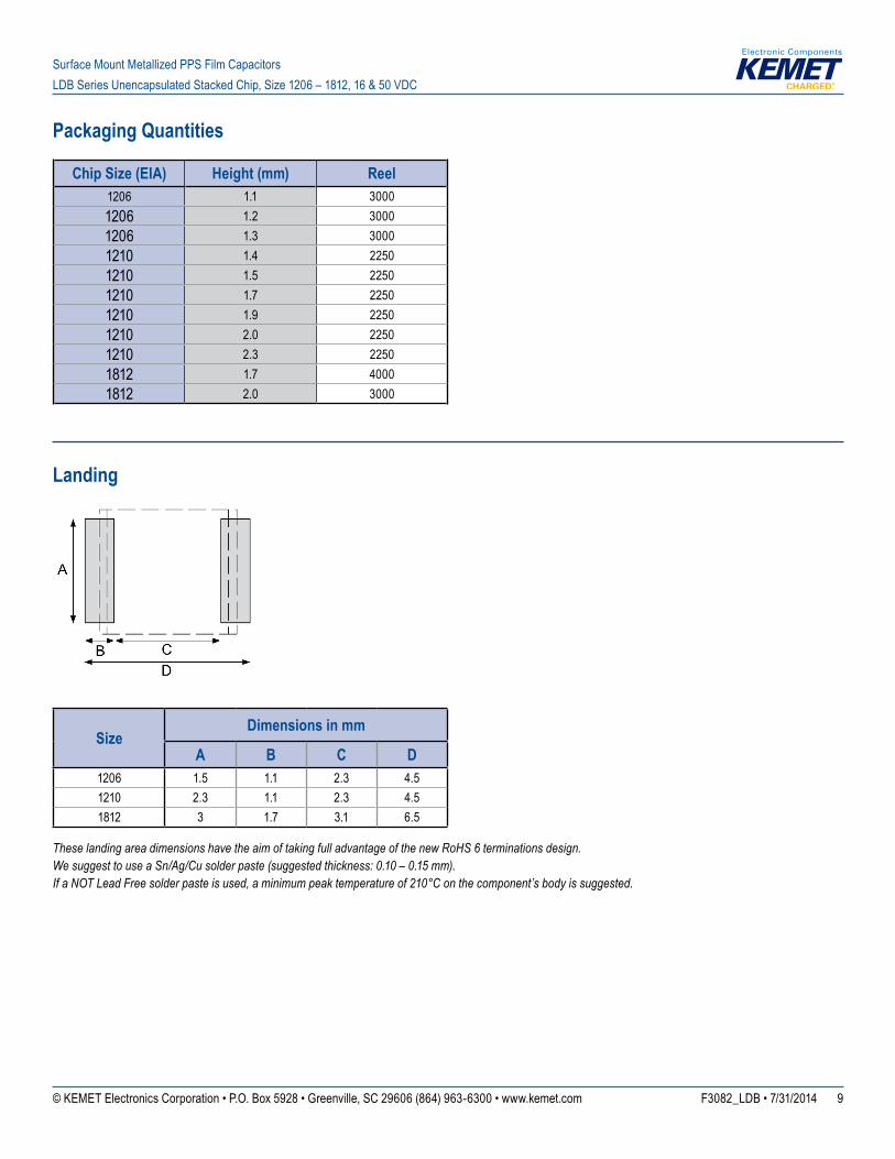
Packaging Quantities
Chip Size (EIA) Height (mm) Reel1206 1.1 30001206 1.2 30001206 1.3 30001210 1.4 22501210 1.5 22501210 1.7 22501210 1.9 22501210 2.0 22501210 2.3 22501812 1.7 40001812 2.0 3000
Landing
SizeDimensions in mm
A B C D1206 1.5 1.1 2.3 4.51210 2.3 1.1 2.3 4.51812 3 1.7 3.1 6.5
These landing area dimensions have the aim of taking full advantage of the new RoHS 6 terminations design.We suggest to use a Sn/Ag/Cu solder paste (suggested thickness: 0.10 – 0.15 mm).If a NOT Lead Free solder paste is used, a minimum peak temperature of 210°C on the component’s body is suggested.
© KEMET Electronics Corporation • P.O. Box 5928 • Greenville, SC 29606 (864) 963-6300 • www.kemet.com F3082_LDB • 7/31/2014 10
Surface Mount Metallized PPS Film Capacitors LDB Series Unencapsulated Stacked Chip, Size 1206 – 1812, 16 & 50 VDC
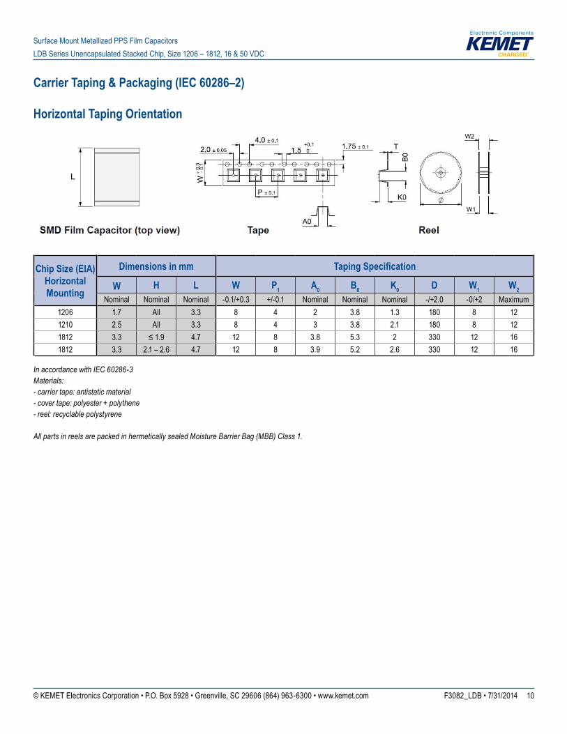
Carrier Taping & Packaging (IEC 60286–2)
Horizontal Taping Orientation
Chip Size (EIA)Horizontal Mounting
Dimensions in mm Taping Specification
W H L W P1 A0 B0 K0 D W1 W2Nominal Nominal Nominal -0.1/+0.3 +/-0.1 Nominal Nominal Nominal -/+2.0 -0/+2 Maximum
1206 1.7 All 3.3 8 4 2 3.8 1.3 180 8 121210 2.5 All 3.3 8 4 3 3.8 2.1 180 8 121812 3.3 ≤1.9 4.7 12 8 3.8 5.3 2 330 12 161812 3.3 2.1 – 2.6 4.7 12 8 3.9 5.2 2.6 330 12 16
In accordance with IEC 60286-3Materials: - carrier tape: antistatic material - cover tape: polyester + polythene - reel: recyclable polystyrene All parts in reels are packed in hermetically sealed Moisture Barrier Bag (MBB) Class 1.
© KEMET Electronics Corporation • P.O. Box 5928 • Greenville, SC 29606 (864) 963-6300 • www.kemet.com F3082_LDB • 7/31/2014 11
Surface Mount Metallized PPS Film Capacitors LDB Series Unencapsulated Stacked Chip, Size 1206 – 1812, 16 & 50 VDC
KEMET Corporation World Headquarters
2835 KEMET WaySimpsonville, SC 29681
Mailing Address:P.O. Box 5928 Greenville, SC 29606
www.kemet.com Tel: 864-963-6300 Fax: 864-963-6521
Corporate Offi cesFort Lauderdale, FLTel: 954-766-2800
North America
SoutheastLake Mary, FLTel: 407-855-8886
NortheastWilmington, MATel: 978-658-1663
CentralNovi, MITel: 248-306-9353
WestMilpitas, CATel: 408-433-9950
Mexico Guadalajara, Jalisco Tel: 52-33-3123-2141
Europe
Southern EuropeParis, FranceTel: 33-1-4646-1006
Sasso Marconi, ItalyTel: 39-051-939111
Central EuropeLandsberg, Germany Tel: 49-8191-3350800
Kamen, GermanyTel: 49-2307-438110
Northern EuropeBishop’s Stortford, United Kingdom Tel: 44-1279-460122
Espoo, FinlandTel: 358-9-5406-5000
Asia
Northeast AsiaHong KongTel: 852-2305-1168
Shenzhen, ChinaTel: 86-755-2518-1306
Beijing, ChinaTel: 86-10-5829-1711
Shanghai, ChinaTel: 86-21-6447-0707
Taipei, TaiwanTel: 886-2-27528585
Southeast AsiaSingaporeTel: 65-6586-1900
Penang, MalaysiaTel: 60-4-6430200
Bangalore, IndiaTel: 91-806-53-76817
Note: KEMET reserves the right to modify minor details of internal and external construction at any time in the interest of product improvement. KEMET does not assume any responsibility for infringement that might result from the use of KEMET Capacitors in potential circuit designs. KEMET is a registered trademark of KEMET Electronics Corporation.
© KEMET Electronics Corporation • P.O. Box 5928 • Greenville, SC 29606 (864) 963-6300 • www.kemet.com F3082_LDB • 7/31/2014 12
Surface Mount Metallized PPS Film Capacitors LDB Series Unencapsulated Stacked Chip, Size 1206 – 1812, 16 & 50 VDC
DisclaimerAllproductspecifications,statements,informationanddata(collectively,the“Information”)inthisdatasheetaresubjecttochange.Thecustomerisresponsibleforcheckingandverifying the extent to which the Information contained in this publication is applicable to an order at the time the order is placed.
All Information given herein is believed to be accurate and reliable, but it is presented without guarantee, warranty, or responsibility of any kind, expressed or implied.
StatementsofsuitabilityforcertainapplicationsarebasedonKEMETElectronicsCorporation’s(“KEMET”)knowledgeoftypicaloperatingconditionsforsuchapplications,butarenotintendedtoconstitute–andKEMETspecificallydisclaims–anywarrantyconcerningsuitabilityforaspecificcustomerapplicationoruse.TheInformationisintendedforuseonlyby customers who have the requisite experience and capability to determine the correct products for their application. Any technical advice inferred from this Information or otherwise provided by KEMET with reference to the use of KEMET’s products is given gratis, and KEMET assumes no obligation or liability for the advice given or results obtained.
Although KEMET designs and manufactures its products to the most stringent quality and safety standards, given the current state of the art, isolated component failures may still occur. Accordingly, customer applications which require a high degree of reliability or safety should employ suitable designs or other safeguards (such as installation of protective circuitry or redundancies) in order to ensure that the failure of an electrical component does not result in a risk of personal injury or property damage.
Although all product–related warnings, cautions and notes must be observed, the customer should not assume that all safety measures are indicted or that other measures may not be required.


![[Ldb] -lei_nº_9.394_de_20_de_dezembro_de_1996](https://img.pdfslide.net/doc/110x75/557ccdf0d8b42a43438b505f/ldb-leino9394de20dedezembrode1996.jpg)