Embed Size (px)
Citation preview
Journal for Technology of Plasticity, Vol. 40 (2015), Number 1
*Corresponding author’s email: [email protected]
SURFACE SHEET’S MORPHOLOGY DURING ITS DIVISION USING CONVENTIONAL AND UNCONVENTIONAL TECHNOLOGIES
Milan Dvořák*, Milan Kalivoda, Karel Osička, Kateřina Mouralová, Martin Slaný
Institute of Manufacturing Technology, Faculty of Mechanical Engineering, Brno University of Technology, Czech Republic
ABSTRACT
This article discusses the morphology of the sheared surface of the steel sheet samples from corrosion resistant material. The following technology to treat one of the cut edges was milling technology. As a comparative technology wire method EDM (Electrical Discharge Machining) cutting was chosen. The surface morphology was compared after the operation of bending with different bending radius. Bends were performed on a special fixture with the possibility of setting bend radius step by step. Key words: corrosion resistant steel sheet, shearing, bending, surface morphology, wire electrical discharge machining 1. INTRODUCTION In industrial conditions during the processing of stainless sheet metal a number of minor defects may appear, such as a problem of the status of cut edges and their possible changes after bending process. Particularly this fact is highlighted if these individual parts are built into more complex assemblies, like in case of components of the exhaust pipe system for an upper middle class cars, where the condition of sheared edges may affect the resistance to corrosion [1,2,5,6,8]. 2. PARAMETERS OF THE SHEET FOR EXPERIMENT The material used in experiments was a corrosion resistant sheet ČSN ISO 1.4301(EN 10027-2), X5CrNi18-10 [3], thickness of 1.5mm with following characteristics:
14
Journal for Technology of Plasticity, Vol. 40 (2015), Number 1
• Tensile Strength Rm = 490 to 686 MPa, • Yield Point Re= 186 MPa, • Ductility A50 = 37 to 45 %, • Tensile Modulus E = 199000 MPa.
The material composition is shown in table 1.
Table 1 - Chemical Composition of Materials ČSN ISO 1.4301 Element C Si Mn Cr Mo Ni Other
Weight % ≤0,07 ≤1 ≤2 17,0 - 19,0 - 8,5 - 10,5 -
3. METAL SHEARING The technology and process parameters of shearing corrosion-resistant material is influenced by the direction of the fibres of the sheet workpiece. If fibre orientation after sheet rolling is not know (no evidence from the manufacturer), procedure for determining the direction of the fibres is a difficult task. The theoretical formula for calculating the shearing forces on sheets in table shear with straight blades is given by expression (1), but obtained results may differ significantly from actual (practical) values..
s psF n S τ= ⋅ ⋅ (1) where:
Fs [N] - cutting power n- factor dulling of the cutting tool (about 1.2) S [mm2] - shear area ��� [MPa] - shear strength
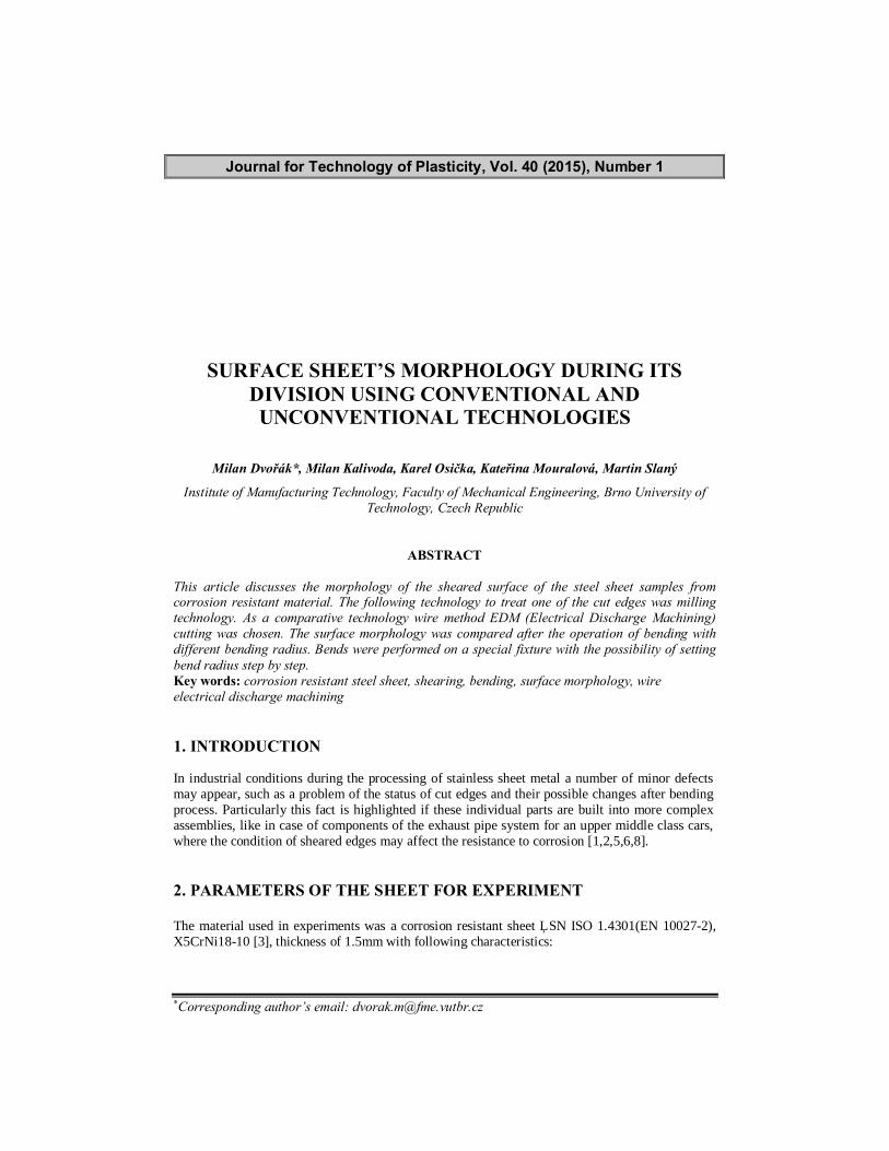
The shearing process of a sheet begins with elastic deformation and continues with plastic deformation. After achieving the tensile strength of the material, local plastic deformation takes place resulting in local yielding of material (Fig. 1). Very soon first (initial) cracks occur which are then spread leading to material fracture (separation). The maximum shear stress is acting on the cutting edges of the punch and die. Shearing process is considered as plane deformation, but this assumption is not exactly correct. Stress state scheme is similar to the processes of bulk forming and stress amount varies in dependence of the sheet thickness (shearing zone). Having this in mid, the improved equation for calculating shear force has the following form: ( ) sins mF R L s x α= ⋅ ⋅ − ⋅ (2) where:
Fs [N] - cutting force, Rm [MPa] - ultimate tensile strength, L [mm] - cutting length, s [mm] - thickness of sheet metal, x [mm] - punch penetration depth into the material. α [°] - angle of inclination of cutting edges in the contact punch.
15
Journal for Technology of Plasticity, Vol. 40 (2015), Number 1
Metal cutting method significantly affects the final quality of the surface. It can be said that this influence is revealed primarily by changing the surface quality and therefore these changes should be evaluated, for example by monitoring surface integrity. Integrity of the surface is the image of the conditions in which an area is formed. It is also necessary to consider effects of individual technological methods on the resulting quality of the machined surface. These must be assessed in relation to the functional requirements for the entire product. Currently, there is no defined a clear method that could evaluate the new constructed area in a comprehensive manner in terms of its integrity and hence, the most reliable evaluation of the integrity of the surface is still the proper operation of the device. In the case that it is necessary to predict behaviour of the surface integrity, it is necessary to use a combination of individual variables measuring surface roughness and visual display. Partial disadvantage of this approach can be a subjective view of the individual results [8,10,11].
Fig.1 - Focal point for plastic deformation
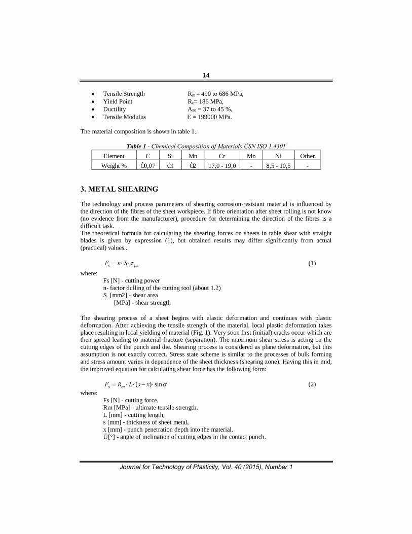
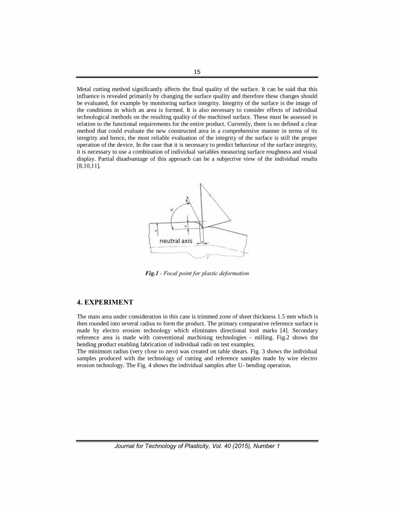
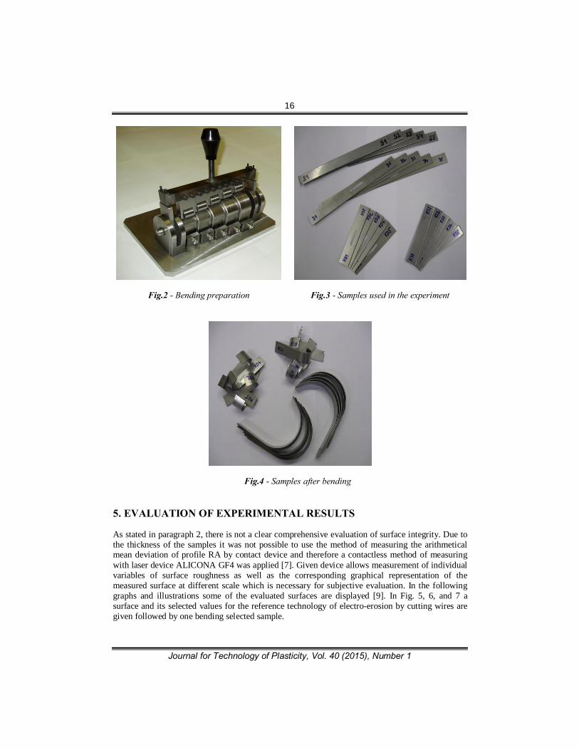
4. EXPERIMENT The main area under consideration in this case is trimmed zone of sheet thickness 1.5 mm which is then rounded into several radius to form the product. The primary comparative reference surface is made by electro erosion technology which eliminates directional tool marks [4]. Secondary reference area is made with conventional machining technologies - milling. Fig.2 shows the bending product enabling fabrication of individual radii on test examples. The minimum radius (very close to zero) was created on table shears. Fig. 3 shows the individual samples produced with the technology of cutting and reference samples made by wire electro erosion technology. The Fig. 4 shows the individual samples after U- bending operation.
16
Journal for Technology of Plasticity, Vol. 40 (2015), Number 1
Fig.2 - Bending preparation
Fig.3 - Samples used in the experiment
Fig.4 - Samples after bending
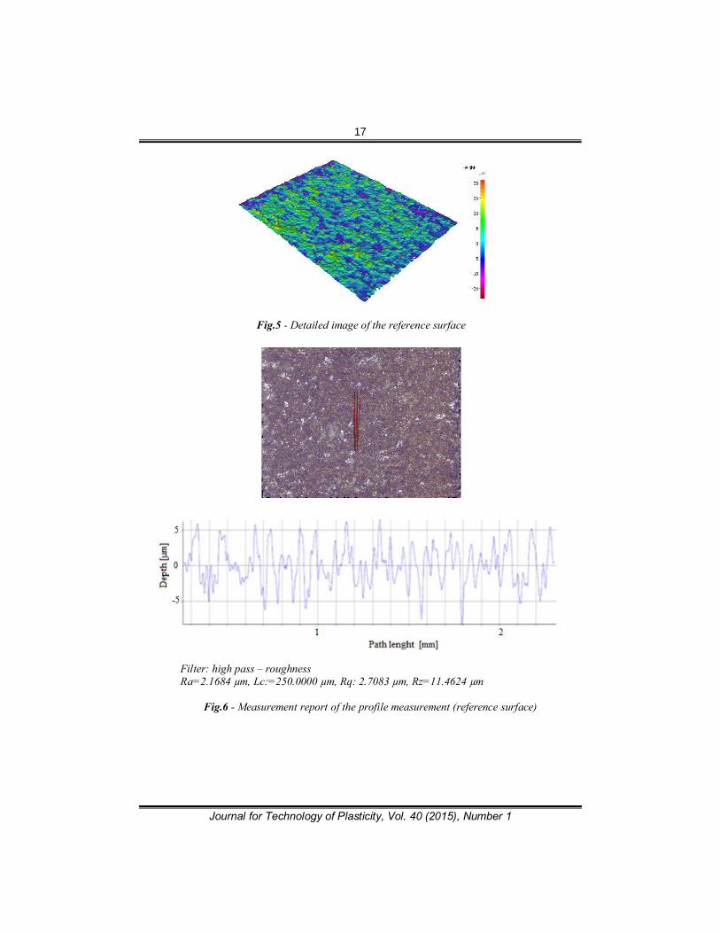
5. EVALUATION OF EXPERIMENTAL RESULTS As stated in paragraph 2, there is not a clear comprehensive evaluation of surface integrity. Due to the thickness of the samples it was not possible to use the method of measuring the arithmetical mean deviation of profile RA by contact device and therefore a contactless method of measuring with laser device ALICONA GF4 was applied [7]. Given device allows measurement of individual variables of surface roughness as well as the corresponding graphical representation of the measured surface at different scale which is necessary for subjective evaluation. In the following graphs and illustrations some of the evaluated surfaces are displayed [9]. In Fig. 5, 6, and 7 a surface and its selected values for the reference technology of electro-erosion by cutting wires are given followed by one bending selected sample.
17
Journal for Technology of Plasticity, Vol. 40 (2015), Number 1
Fig.5 - Detailed image of the reference surface
Filter: high pass – roughness Ra=2.1684 µm, Lc:=250.0000 µm, Rq: 2.7083 µm, Rz=11.4624 µm
Fig.6 - Measurement report of the profile measurement (reference surface)
18
Journal for Technology of Plasticity, Vol. 40 (2015), Number 1
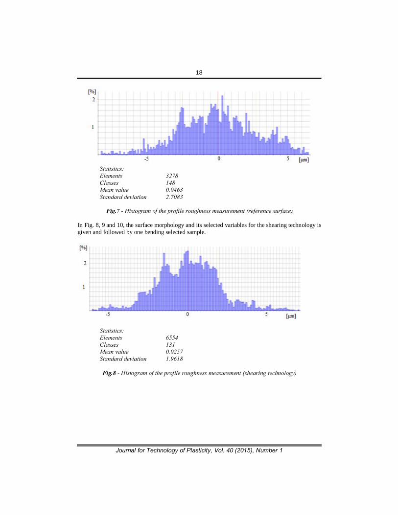
Statistics: Elements 3278 Classes 148 Mean value 0.0463 Standard deviation 2.7083
Fig.7 - Histogram of the profile roughness measurement (reference surface)
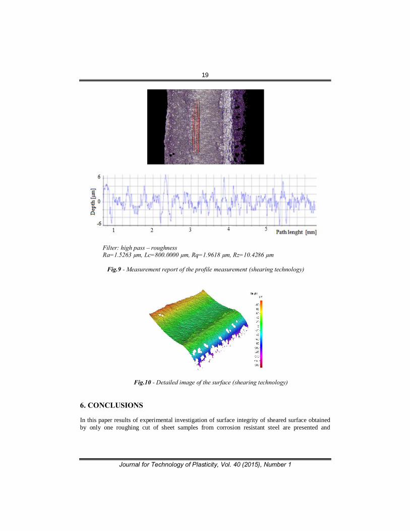
In Fig. 8, 9 and 10, the surface morphology and its selected variables for the shearing technology is given and followed by one bending selected sample.
Statistics: Elements 6554 Classes 131 Mean value 0.0257 Standard deviation 1.9618
Fig.8 - Histogram of the profile roughness measurement (shearing technology)
19
Journal for Technology of Plasticity, Vol. 40 (2015), Number 1
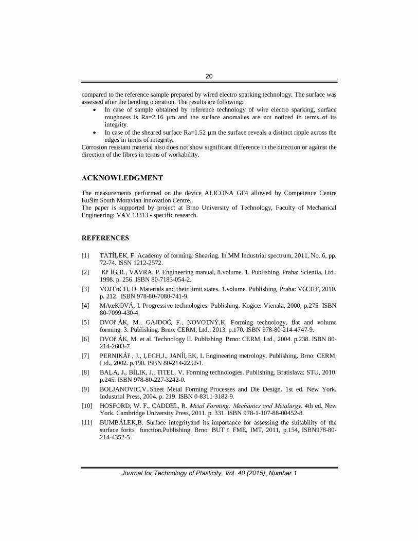
Filter: high pass – roughness Ra=1.5263 µm, Lc=800.0000 µm, Rq=1.9618 µm, Rz=10.4286 µm
Fig.9 - Measurement report of the profile measurement (shearing technology)
Fig.10 - Detailed image of the surface (shearing technology) 6. CONCLUSIONS In this paper results of experimental investigation of surface integrity of sheared surface obtained by only one roughing cut of sheet samples from corrosion resistant steel are presented and
20
Journal for Technology of Plasticity, Vol. 40 (2015), Number 1
compared to the reference sample prepared by wired electro sparking technology. The surface was assessed after the bending operation. The results are following:
• In case of sample obtained by reference technology of wire electro sparking, surface roughness is Ra=2.16 µm and the surface anomalies are not noticed in terms of its integrity.
• In case of the sheared surface Ra=1.52 µm the surface reveals a distinct ripple across the edges in terms of integrity.
Corrosion resistant material also does not show significant difference in the direction or against the direction of the fibres in terms of workability. ACKNOWLEDGMENT The measurements performed on the device ALICONA GF4 allowed by Competence Centre Kuřim South Moravian Innovation Centre. The paper is supported by project at Brno University of Technology, Faculty of Mechanical Engineering: VAV 13313 - specific research. REFERENCES [1] TATÍČEK, F. Academy of forming: Shearing. In MM Industrial spectrum, 2011, No. 6, pp.
72-74. ISSN 1212-2572. [2] KŘÍŽ, R., VÁVRA, P. Engineering manual, 8.volume. 1. Publishing. Praha: Scientia, Ltd.,
1998. p. 256. ISBN 80-7183-054-2. [3] VOJTĚCH, D. Materials and their limit states. 1.volume. Publishing. Praha: VŠCHT, 2010.
p. 212. ISBN 978-80-7080-741-9. [4] MAŇKOVÁ, I. Progressive technologies. Publishing. Košice: Vienala, 2000, p.275. ISBN
80-7099-430-4. [5] DVOŘÁK, M., GAJDOŠ, F., NOVOTNÝ,K. Forming technology, flat and volume
forming. 3. Publishing. Brno: CERM, Ltd., 2013. p.170. ISBN 978-80-214-4747-9. [6] DVOŘÁK, M. et al. Technology II. Publishing. Brno: CERM, Ltd., 2004. p.238. ISBN 80-
214-2683-7. [7] PERNIKÁŘ, J., ČECH,J., JANÍČEK, L Engineering metrology. Publishing. Brno: CERM,
Ltd., 2002. p.190. ISBN 80-214-2252-1. [8] BAČA, J., BÍLIK, J., TITEL, V. Forming technologies. Publishing. Bratislava: STU, 2010.
p.245. ISBN 978-80-227-3242-0. [9] BOLJANOVIC,V..Sheet Metal Forming Processes and Die Design. 1st ed. New York.
Industrial Press, 2004. p. 219. ISBN 0-8311-3182-9. [10] HOSFORD, W. F., CADDEL, R. Metal Forming: Mechanics and Metalurgy. 4th ed. New
York. Cambridge University Press, 2011. p. 331. ISBN 978-1-107-88-00452-8. [11] BUMBÁLEK,B. Surface integrityand its importance for assessing the suitability of the
surface forits function.Publishing. Brno: BUT – FME, IMT, 2011, p.154, ISBN978-80-214-4352-5.
21
Journal for Technology of Plasticity, Vol. 40 (2015), Number 1
MORFOLOGIJA REZNE IVICE LIMA DOBIJENA KONVENCIONALNIM I NEKONVENCIONALNIM
TEHNOLOGIJAMA
Milan Dvořák*, Milan Kalivoda, Karel Osička, Kateřina Mouralová, Martin Slaný
Institute of Manufacturing Technology, Faculty of Mechanical Engineering, Brno University of Technology, Czech Republic
REZIME
U ovom radu vršena su morfološka ispitivanja rezne ivice uzoraka od nerđajućeg lima dobijenih odsecanjem na makazama sa pravim paralelnim noževima. Kao sledeća tehnologija za obradu reznih ivica korišćena je tehnologija glodanja. Kao komparativna tehnologija usvojena je elektro-erozivna obrada žicom. Morfologije površina poređene su nakon operacije savijanja sa različitim radijusima. Savijeni elementi dobijeni su pomoću specijalnog alata koji je omogućavao fino podešavanje radijusa savijanja. Key words: nerđajući čelik, sečenje, savijanje, morfologija površina, elektro-erozivna obrada