Embed Size (px)
Citation preview

2
• Introduction
• Modelling
• Results
• Conclusions
Agenda

3
Introduction
4
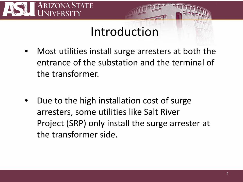
Introduction• Most utilities install surge arresters at both the
entrance of the substation and the terminal of the transformer.
• Due to the high installation cost of surge arresters, some utilities like Salt River Project (SRP) only install the surge arrester at the transformer side.

5
IntroductionTwo major concerns:
• Critical point • maximum recommended length of the transmission
line before an arrester needs to be applied
• Performance for different surge arrester configurations

6
IntroductionDefinition of critical pointLightning strokes are applied at different distances from the entrance point. The corresponding lightning stroke location of the maximum voltage at the entrance of the substation or the terminal of the transformer is defined as the critical point.
X ZY
7
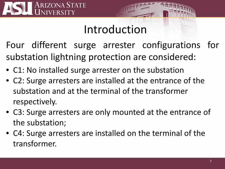
IntroductionFour different surge arrester configurations forsubstation lightning protection are considered:• C1: No installed surge arrester on the substation • C2: Surge arresters are installed at the entrance of the
substation and at the terminal of the transformer respectively.
• C3: Surge arresters are only mounted at the entrance of the substation;
• C4: Surge arresters are installed on the terminal of the transformer.

8
Modelling
9
Modelling Fast front transient model for :
• a practical SRP 500-230 kV substation (with realfield data)
• a few spans of the 230kV transmission line
This Model is developed using PSCAD 4.6.0.
SRP denotes Salt River Project which is a utility located in Arizona.

10
Modelling Simulation procedures :Step 1. Model 230kV transmission line and the connected substation in PSCAD using the field data.Step 2. Changing the distance from the lightning stroke location to the entrance of the substation. Step 3. repeating step (2) for different protection configurations.
X ZY
0 200 400 600 800 1000
100
200
300
400
500
600
700
(d) C4- One surge arreste r on Point Z
Peak
volta
ge a
mpli
tude
(kV)
Distance to Point X (m)
UY-phase A UY-phase B
UY-phase C UZ-phase A UZ-phase B UZ-phase C

11
Results

12
C2 : surge arresters are installed at both the entrance of thesubstation and the terminal of the transformer.
0 40 80 120 160
0
200
400
0 40 80 120 160
0
200
400
0 40 80 120 1600
200
400
600
0 40 80 120 1600
200
400
600
0 40 80 120 160
0
6
12
18
0 40 80 120 160
0
6
12
18
(iii) (iii)
(ii) (ii)
(i)
Vol
tage
(kV
)
T ime (µs)
Phase A Phase B Phase C
Vol
tage
(kV
)
Time (µs)
Phase A Phase B Phase C
(b) Terminal of the transformer
Ene
rgy
(kJ)
Time (µs)
Phase A Phase B Phase C
(a) Entrance of the substation
(i)
Ene
rgy
(kJ)
Time (µs)
Phase A Phase B Phase C
Cur
rent
(kA
)
T ime (µs)
Phase A Phase B Phase C
Cur
ren
t (kA
)
Time (µs)
Phase A Phase B Phase C
Arrester Voltage
Arrester Energy duties
Arrester Current
Direct stroke — Phase B is hit by the lightning stroke
Lightning stroke distance = 20m

13
Voltage-distance curves X ZY
• The voltages on phase A and phase C are far less than the voltage on phase B.
Critical Point
0 200 400 600 800 1000
200
400600800
100012001400
16001800
0 200 400 600 800 1000
100
200
300
400
500
600
700
0 200 400 600 800 1000
100
200
300
400
500
600
700
800
0 200 400 600 800 1000
100
200
300
400
500
600
700
Peak
vol
tage
am
plitu
de (k
V)
Distance to Point X (m)
UY-phase A UY-phase B
UY-phase C UZ -phase A UZ -phase B UZ -phase C
Pea
k vo
ltage
am
plitu
de (k
V)
Distance to Point X (m)
UY-phase A UY-phase B UY-phase C
UZ-phase A UZ-phase B UZ-phase C
Peak
vol
tage
am
plitu
de (k
V)
Distance to Point X (m)
UY-phase A UY-phase B UY-phase C UZ-phase A UZ-phase B
UZ-phase C
(b) C2- Two surge arreste r on both Point Y and Z
(c) C3- One surge ar rester on Point Y (d) C4- One surge arreste r on Point Z
(a) C1-No installed surge arreste r
Pea
k vo
ltage
am
plitu
de (k
V)
Distance to Point X (m)
UY-phase A UY-phase B
UY-phase C UZ-phase A UZ-phase B UZ-phase C
• Most critical points are the closest point to the line entrance of the substation
14
Results
28%
183%
31% 25%
194%
27% 19%
73%
19% 12%
71%
15%
15%
70%
15% 12%
85%
14% 16%
79%
16% 12%
70%
15%
UA,Y UB,Y UC,Y UA,Z UB,Z UC,Z
0
40
80
120
160
200
Um
ax
/ B
IL (%
)
CP=920 m
CP=160m
CP=920mCP=700m
CP=20 m
CP=840mCP=2 0M
CP=20m
CP=20mCP=20m
CP=20m
CP=20m
CP=2 0m
CP=20m
CP=20mCP=20m
CP=20m
CP=20mCP=20m
CP=20m
CP=20mCP=20m
CP=20m
CP=20 m
UA,Y UB,Y UC,Y UA,Z UB,Z UC,Z
0
20
40
60
80
Um
ax
/ B
IL (%
)
UA,Y UB,Y UC,Y UA,Z UB,Z UC,Z
0
20
40
60
80
Um
ax
/ B
IL (
%)
(a) C1 (b) C2
(c) C3 (d) C4UA,Y UB,Y UC,Y UA,Z UB,Z UC,Z
0
20
40
60
80
Um
ax /
BIL
(%
)
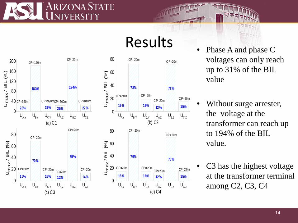
• Phase A and phase C voltages can only reach up to 31% of the BIL value
• Without surge arrester, the voltage at the transformer can reach up to 194% of the BIL value.
• C3 has the highest voltageat the transformer terminalamong C2, C3, C4

15
Voltage-distance curve for Phase B
0 100 200 300 400 500 600 700 800 900 1000300
600
900
1,200
1,500
1,800
UY-C1 UZ-C1 U
Y-C2
UZ-C2
UY-C3
UZ-C3 U
Y-C4
UZ-C4
Distance to Point X (m)
Pea
k vo
ltage
am
plitu
de (k
V) 50 100 150 200 250 300
400
500
600
700
800
P2
P1
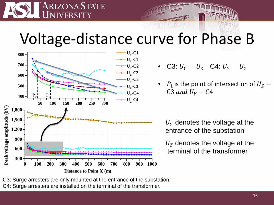
• C3: 𝑈𝑈𝑌𝑌 < 𝑈𝑈𝑍𝑍 C4: 𝑈𝑈𝑌𝑌 > 𝑈𝑈𝑍𝑍
𝑈𝑈𝑌𝑌 - voltage at theentrance of the substation𝑈𝑈𝑍𝑍 - voltage at theterminal of the transformer
C3: Surge arresters are only mounted at the entrance of the substation;C4: Surge arresters are installed on the terminal of the transformer.
16
Voltage-distance curve for Phase B
0 100 200 300 400 500 600 700 800 900 1000300
600
900
1,200
1,500
1,800
UY-C1 UZ-C1 U
Y-C2
UZ-C2
UY-C3
UZ-C3 U
Y-C4
UZ-C4
Distance to Point X (m)
Pea
k vo
ltage
am
plitu
de (k
V) 50 100 150 200 250 300
400
500
600
700
800
P2
P1
• C3: 𝑈𝑈𝑌𝑌 < 𝑈𝑈𝑍𝑍 C4: 𝑈𝑈𝑌𝑌 > 𝑈𝑈𝑍𝑍
• 𝑃𝑃1 is the point of intersection of 𝑈𝑈𝑍𝑍 −C3 𝑎𝑎𝑎𝑎𝑎𝑎 𝑈𝑈𝑌𝑌 − 𝐶𝐶𝐶
𝑈𝑈𝑌𝑌 denotes the voltage at theentrance of the substation
𝑈𝑈𝑍𝑍 denotes the voltage at theterminal of the transformer
C3: Surge arresters are only mounted at the entrance of the substation;C4: Surge arresters are installed on the terminal of the transformer.

17
Voltage-distance curve for Phase B
0 100 200 300 400 500 600 700 800 900 1000300
600
900
1,200
1,500
1,800
UY-C1 UZ-C1 U
Y-C2
UZ-C2
UY-C3
UZ-C3 U
Y-C4
UZ-C4
Distance to Point X (m)
Pea
k vo
ltage
am
plitu
de (k
V) 50 100 150 200 250 300
400
500
600
700
800
P2
P1
• C3: 𝑈𝑈𝑌𝑌 < 𝑈𝑈𝑍𝑍 C4: 𝑈𝑈𝑌𝑌 > 𝑈𝑈𝑍𝑍
• 𝑃𝑃1 is the point of intersection of 𝑈𝑈𝑍𝑍 −C3 𝑎𝑎𝑎𝑎𝑎𝑎 𝑈𝑈𝑌𝑌 − 𝐶𝐶𝐶
• 𝑃𝑃2 is the point of intersection of 𝑈𝑈𝑍𝑍 −C3 𝑎𝑎𝑎𝑎𝑎𝑎 𝑈𝑈𝑍𝑍 − 𝐶𝐶𝐶
C3: Surge arresters are only mounted at the entrance of the substation;C4: Surge arresters are installed on the terminal of the transformer.
𝑈𝑈𝑌𝑌 denotes the voltage at theentrance of the substation
𝑈𝑈𝑍𝑍 denotes the voltage at theterminal of the transformer
18
Voltage-distance curve for Phase B
0 100 200 300 400 500 600 700 800 900 1000300
600
900
1,200
1,500
1,800
UY-C1 UZ-C1 U
Y-C2
UZ-C2
UY-C3
UZ-C3 U
Y-C4
UZ-C4
Distance to Point X (m)
Pea
k vo
ltage
am
plitu
de (k
V) 50 100 150 200 250 300
400
500
600
700
800
P2
P1
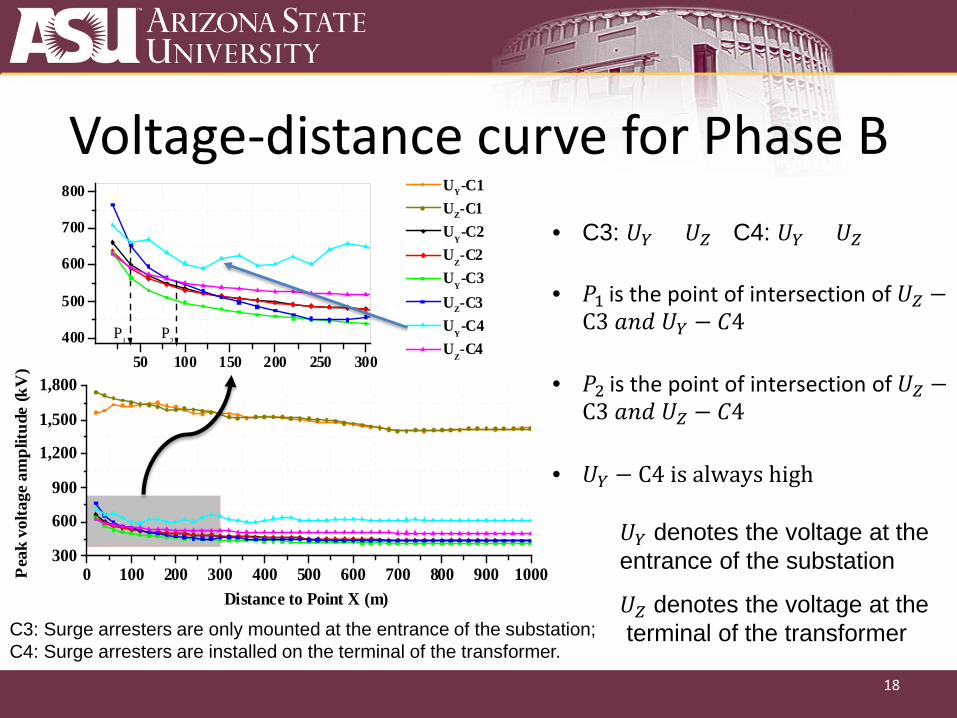
• C3: 𝑈𝑈𝑌𝑌 < 𝑈𝑈𝑍𝑍 C4: 𝑈𝑈𝑌𝑌 > 𝑈𝑈𝑍𝑍
• 𝑈𝑈𝑌𝑌 − C𝐶 is always high
• 𝑃𝑃1 is the point of intersection of 𝑈𝑈𝑍𝑍 −C3 𝑎𝑎𝑎𝑎𝑎𝑎 𝑈𝑈𝑌𝑌 − 𝐶𝐶𝐶
• 𝑃𝑃2 is the point of intersection of 𝑈𝑈𝑍𝑍 −C3 𝑎𝑎𝑎𝑎𝑎𝑎 𝑈𝑈𝑍𝑍 − 𝐶𝐶𝐶
C3: Surge arresters are only mounted at the entrance of the substation;C4: Surge arresters are installed on the terminal of the transformer.
𝑈𝑈𝑌𝑌 denotes the voltage at theentrance of the substation
𝑈𝑈𝑍𝑍 denotes the voltage at theterminal of the transformer

19
Conclusions
20
• The voltage distance curve provides a good visual depiction of thesimulation results.
• For most cases, the overvoltage increases when the distance fromthe lightning stroke location to the line entrance of the substationdecreases. Critical points are typically close to the line entrance ofthe substation.
• Installing surge arresters either on the entrance of the substation orat the terminal of the transformer are sufficient for lightingprotection
• Installing surge arrester only at the terminal of the transformer in the SRP 500-230kV substation is proved to be both adequate and efficient with respect to the lightning performance.
Conclusions