Embed Size (px)
Citation preview
PDHonline Course E288 (2 PDH)
Surge Protection SystemsPerformance and Evaluation
2012
Instructor: Bijan Ghayour, PE
PDH Online | PDH Center5272 Meadow Estates Drive
Fairfax, VA 22030-6658Phone & Fax: 703-988-0088
www.PDHonline.orgwww.PDHcenter.com
An Approved Continuing Education Provider
www.PDHcenter.com PDH Course E288 www.PDHonline.org
TABLE OF CONTENETS
SECTION Page
A. Introduction………………………………………………………………......... 3 B. Surge Protection Design……………………………………………………...... 4 C. Surge Protection Installation…………………………………………………... 6 D. Special Requirements for Fire Alarm, Communications and Related Systems.. 10 E. Surge Protection Performance and Evaluation Criteria………………………... 11
Appendix A- Surge Protection Let-Through by Excessive Lead Length………… A-1
© Bijan Ghayour P.E. Page 2 of 21
www.PDHcenter.com PDH Course E288 www.PDHonline.org
A. INTRODUCTION 1. Surge protection should be considered as part of the overall facility design criteria.
The extent to which surge protection will be required depends on the facility’s mission and the facility occupant’s reliability target. Surge protection should be applied to the following types of facilities:
a. Medical treatment facilities.
b. Petroleum, oil, and lubricant storage and dispensing facilities.
c. Critical utility plants and systems
d. Communication facilities and telephone exchanges.
e. Fire stations, including fire alarm, fire control, and radio equipment
f. Critical computer automatic data processing facilities.
g. Air traffic control towers.
h. Security and Security lighting systems.
i. Television systems
j. Coaxial cable systems
k. Intercom systems
l. Electronic equipment data lines
2. Electrical power to the above equipment should be protected against surge transients
in accordance with the criteria presented in this course.
3. Surge protection should be considered for all types of facilities located in the following areas:
a. In regions with a high lightning strike probability (refer to IEEE C62.41, IEEE Recommended Practice on Surge Voltages in Low Voltage AC Power Circuits)
b. Near commercial utility systems with routine substation capacitor switching. 4. The design criteria in this course apply to permanently installed, hard-wired surge
protectors and should not be applied to smaller plug-in type surge protectors, although the principles of surge protection are similar, regardless of the size and location of the surge protector. Specific end-use equipment might still warrant a small plug-in type surge protector even if the facility is protected in accordance with the criteria of this course.
© Bijan Ghayour P.E. Page 3 of 21
5. Point-of-use only surge protection (smaller plug-in types) can be applied by the facility occupant for those facilities with little or no critical equipment. Examples of these types of facilities include residential housing, barracks, warehouses, and other
www.PDHcenter.com PDH Course E288 www.PDHonline.org
facilities in which equipment damage by surge transients will not interfere with the facility’s mission.
6. This materials presented in this course does not apply to electromagnetic interference
(EMI) filters installed on, or connected to, 600 V or lower potential circuits and listed in accordance with UL 1283, Electromagnetic Interference Filters.
B. SURGE PROTECTION DESIGN 1. Parallel Versus Series Protection
a. Surge protectors within the scope of this course should normally be of the parallel type rather than the series type.
b. Parallel surge protectors are connected in parallel with the circuit and operate when a transient voltage exceeds a preset limit. Parallel surge protectors have little interaction with the circuit under normal conditions.
c. Series surge protectors are connected in series with the circuit and must be capable of carrying the circuit’s full load current. Also, loss of the series surge protector will mean loss of power to all downstream equipment. For this reason, series surge protectors are usually used only to protect individual loads and usually include some level of filtering also.
2. Multiple Layer Protection Design
© Bijan Ghayour P.E. Page 4 of 21
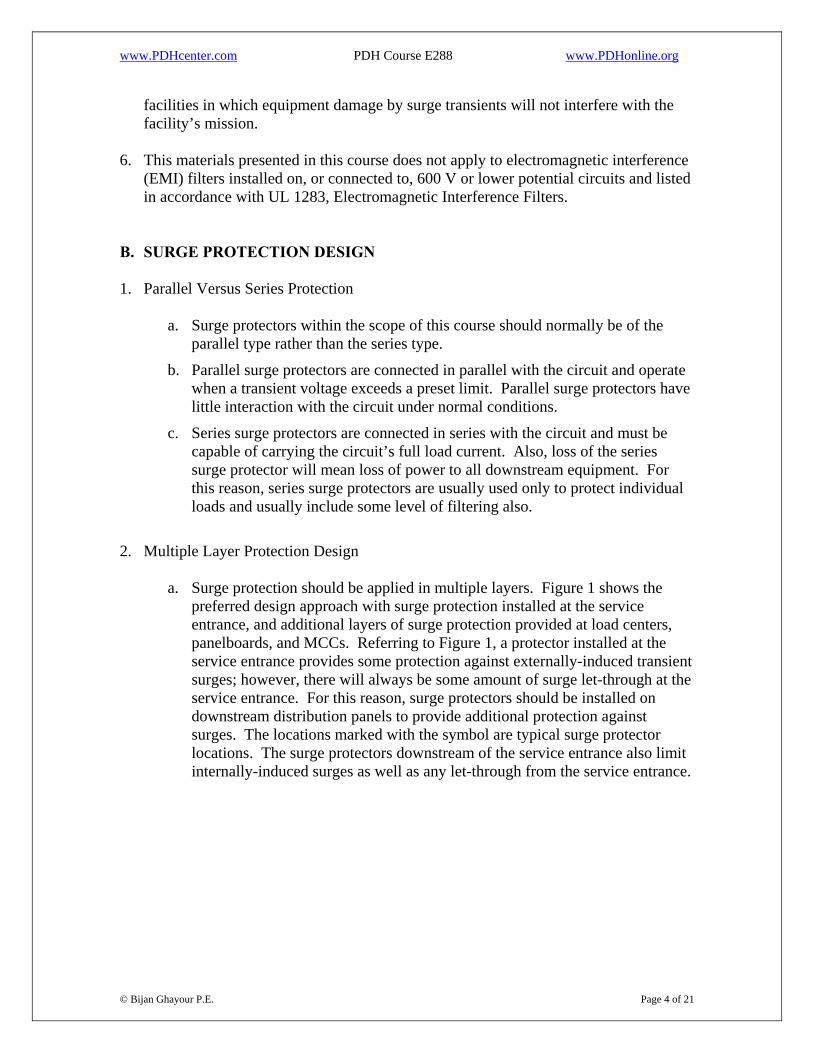
a. Surge protection should be applied in multiple layers. Figure 1 shows the preferred design approach with surge protection installed at the service entrance, and additional layers of surge protection provided at load centers, panelboards, and MCCs. Referring to Figure 1, a protector installed at the service entrance provides some protection against externally-induced transient surges; however, there will always be some amount of surge let-through at the service entrance. For this reason, surge protectors should be installed on downstream distribution panels to provide additional protection against surges. The locations marked with the symbol are typical surge protector locations. The surge protectors downstream of the service entrance also limit internally-induced surges as well as any let-through from the service entrance.
www.PDHcenter.com PDH Course E288 www.PDHonline.org
Figure 1. Simplified Facility Layout
b. Critical loads downstream of the distribution panels should have an additional level of surge protection as shown above. Switching loads such as MCCs should have surge protection to limit the transmission of switching transients to the rest of the facility. It is not necessary to install a surge protector on every panelboard in the facility; the selection of which panelboards should have surge protection depends on the importance of the loads served by each panelboard. HVAC equipment usually contain electronic controls that are sensitive to surges. Lighting electronic ballasts often are equipped with internal surge protection; however, once installed, there is often no easy method of confirming that the internal protection is either present or functional.
c. The surge protector at the service entrance must have a minimum surge current rating of 80,000 amperes per phase or per protection mode. Downstream surge protectors must have a minimum surge current rating of 40,000 amperes per phase or per protection mode. Refer to Section E for additional equipment ratings.
d. By the arrangement shown in Figure 1, protection is provided within the facility for both internally and externally induced transient surges. Proper operation of this cascaded design requires that the installation criteria specified in Section C are met. For example, excessive lead length on a surge protector could mean that it would never respond to a surge event; the other surge protectors would respond first.
e. Point-of-use (plug-in type) surge protectors should be used to protect specific critical equipment that plugs into wall receptacles.
© Bijan Ghayour P.E. Page 5 of 21
www.PDHcenter.com PDH Course E288 www.PDHonline.org
C. SURGE PROTECTION INSTALLATION 1. Minimizing Lead Length for Parallel Surge Protectors.
a. Lead length refers to the length of conductor between the circuit connection and the surge protector, and is the critical installation attribute for parallel-type surge protectors. For typical installations, the lead conductor has negligible resistance, but a significant inductance when subjected to a high frequency surge transient. This inductance can develop a substantial voltage drop under surge conditions, thereby proportionately increasing the let-through voltage. Refer to Appendix A for an example calculation of the lead length effect.
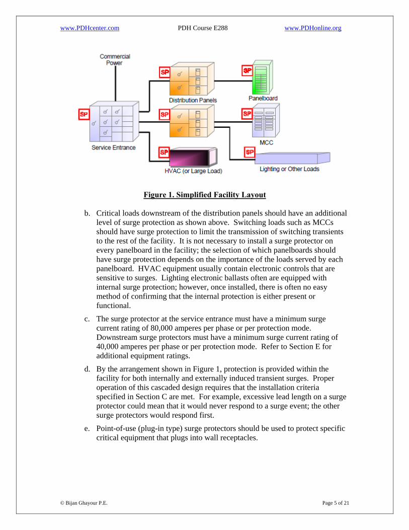
b. Some lead length is unavoidable in an installation; however, every effort should be made to minimize the lead length and associated inductance. Figures 2 and 3 show examples of optimal installations in which the lead conductors are less than 1 foot in length. Notice that the leads have been connected to the circuit breaker panel without making any high-inductance coils or sharp bends in the conductors.
Figure 2. Optimal Installation of Surge Protector Leads – First Example
© Bijan Ghayour P.E. Page 6 of 21
www.PDHcenter.com PDH Course E288 www.PDHonline.org
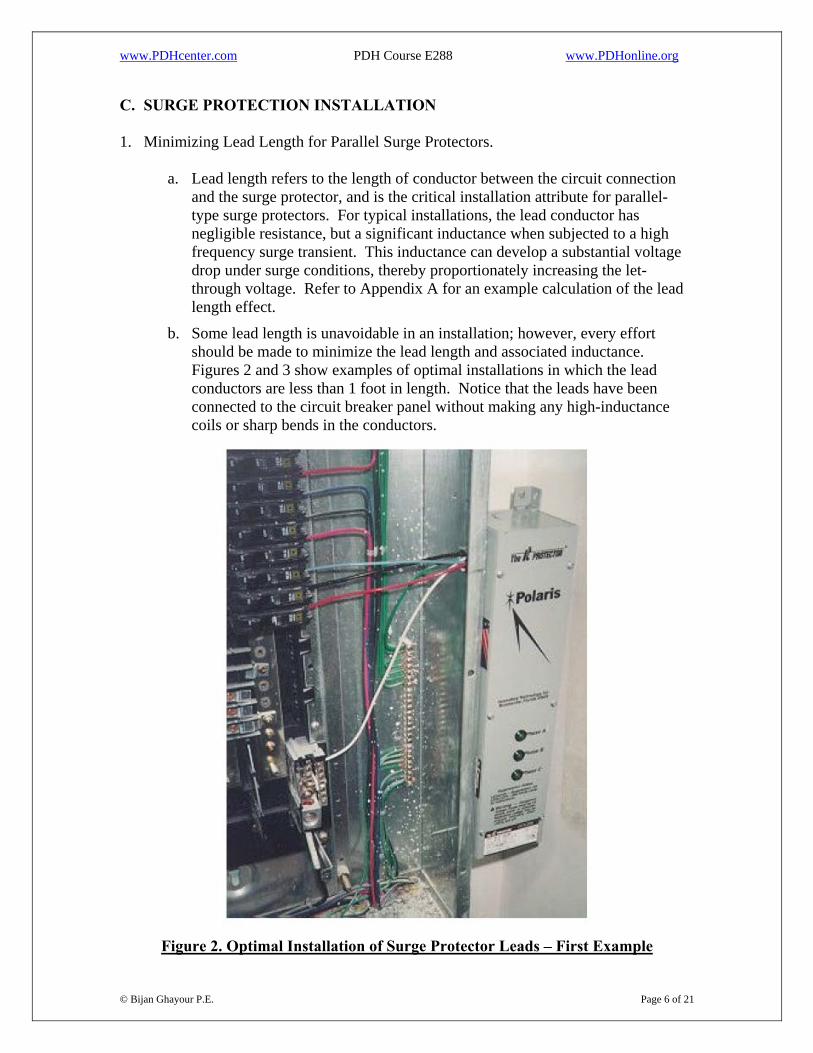
Figure 3. Optimal Installation of Surge Protector Leads – Second Example
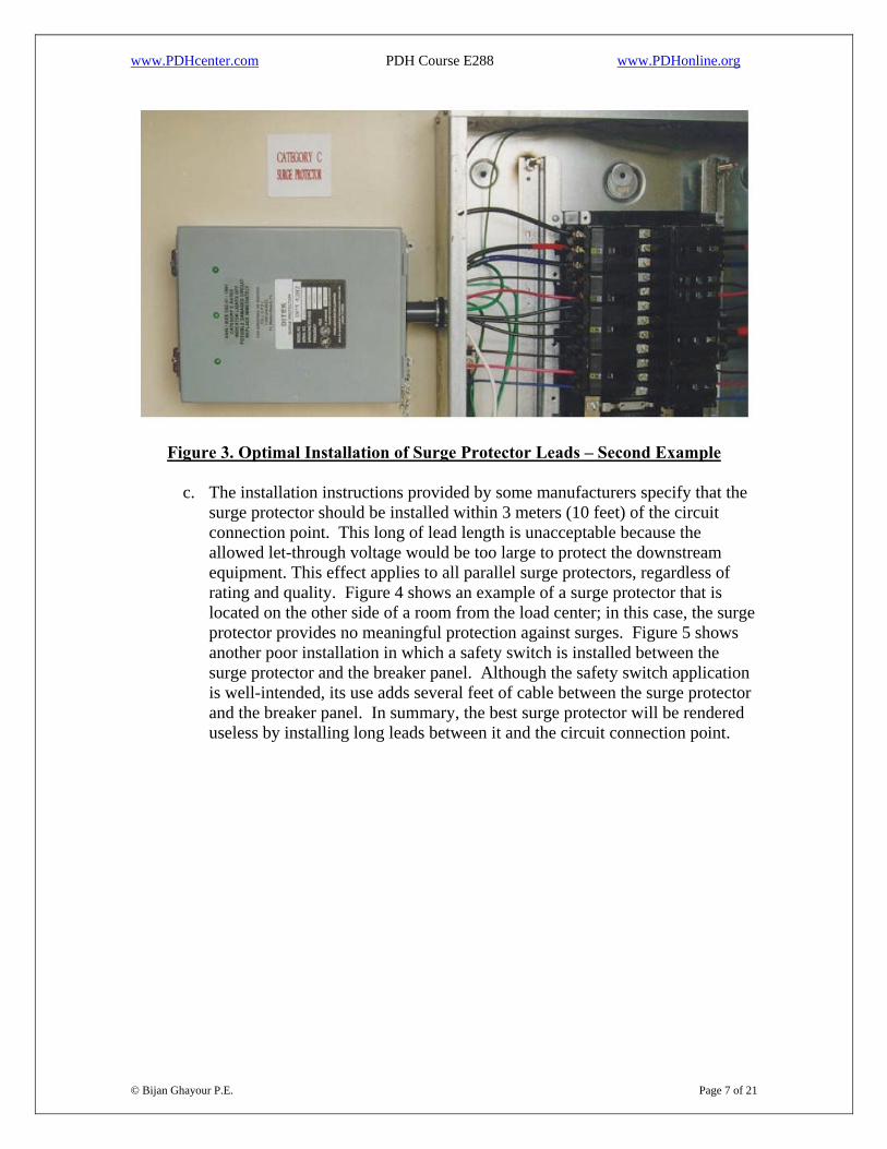
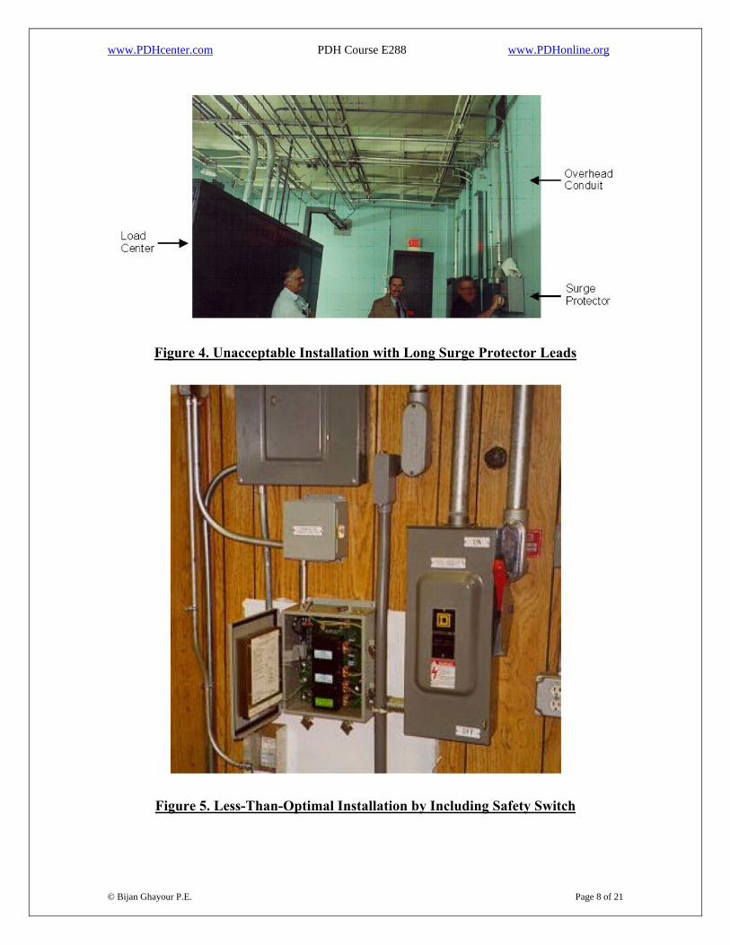
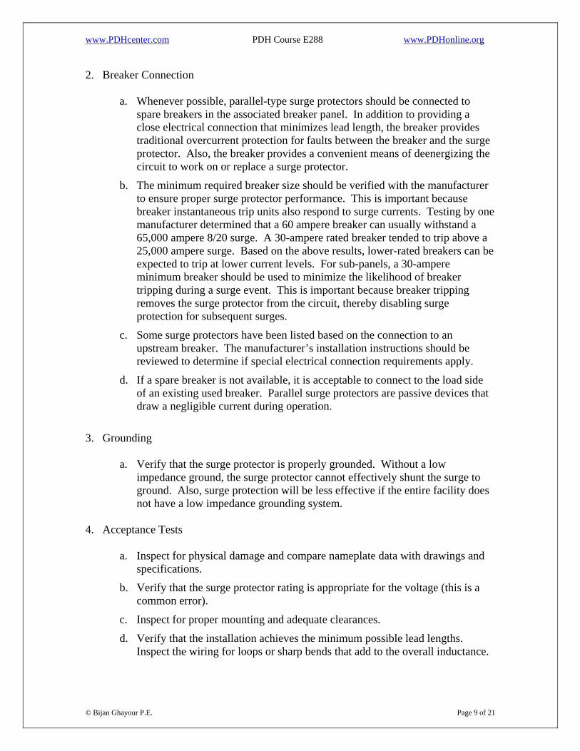
c. The installation instructions provided by some manufacturers specify that the surge protector should be installed within 3 meters (10 feet) of the circuit connection point. This long of lead length is unacceptable because the allowed let-through voltage would be too large to protect the downstream equipment. This effect applies to all parallel surge protectors, regardless of rating and quality. Figure 4 shows an example of a surge protector that is located on the other side of a room from the load center; in this case, the surge protector provides no meaningful protection against surges. Figure 5 shows another poor installation in which a safety switch is installed between the surge protector and the breaker panel. Although the safety switch application is well-intended, its use adds several feet of cable between the surge protector and the breaker panel. In summary, the best surge protector will be rendered useless by installing long leads between it and the circuit connection point.
© Bijan Ghayour P.E. Page 7 of 21
www.PDHcenter.com PDH Course E288 www.PDHonline.org
Figure 4. Unacceptable Installation with Long Surge Protector Leads
Figure 5. Less-Than-Optimal Installation by Including Safety Switch
© Bijan Ghayour P.E. Page 8 of 21
www.PDHcenter.com PDH Course E288 www.PDHonline.org
2. Breaker Connection
a. Whenever possible, parallel-type surge protectors should be connected to spare breakers in the associated breaker panel. In addition to providing a close electrical connection that minimizes lead length, the breaker provides traditional overcurrent protection for faults between the breaker and the surge protector. Also, the breaker provides a convenient means of deenergizing the circuit to work on or replace a surge protector.
b. The minimum required breaker size should be verified with the manufacturer to ensure proper surge protector performance. This is important because breaker instantaneous trip units also respond to surge currents. Testing by one manufacturer determined that a 60 ampere breaker can usually withstand a 65,000 ampere 8/20 surge. A 30-ampere rated breaker tended to trip above a 25,000 ampere surge. Based on the above results, lower-rated breakers can be expected to trip at lower current levels. For sub-panels, a 30-ampere minimum breaker should be used to minimize the likelihood of breaker tripping during a surge event. This is important because breaker tripping removes the surge protector from the circuit, thereby disabling surge protection for subsequent surges.
c. Some surge protectors have been listed based on the connection to an upstream breaker. The manufacturer’s installation instructions should be reviewed to determine if special electrical connection requirements apply.
d. If a spare breaker is not available, it is acceptable to connect to the load side of an existing used breaker. Parallel surge protectors are passive devices that draw a negligible current during operation.
3. Grounding
a. Verify that the surge protector is properly grounded. Without a low impedance ground, the surge protector cannot effectively shunt the surge to ground. Also, surge protection will be less effective if the entire facility does not have a low impedance grounding system.
4. Acceptance Tests
a. Inspect for physical damage and compare nameplate data with drawings and specifications.
b. Verify that the surge protector rating is appropriate for the voltage (this is a common error).
c. Inspect for proper mounting and adequate clearances.
© Bijan Ghayour P.E. Page 9 of 21
d. Verify that the installation achieves the minimum possible lead lengths. Inspect the wiring for loops or sharp bends that add to the overall inductance.
www.PDHcenter.com PDH Course E288 www.PDHonline.org
e. Check tightness of connections by using a calibrated torque wrench. Refer to the manufacturer’s instructions or Table 10-1 of International Electrical Testing Association (NETA) ATS, Acceptance Testing Specifications for Electrical Power Distribution Equipment and Systems, for the recommended torque.
f. Check the ground lead on each device for individual attachment to the ground bus or ground electrode.
g. Perform insulation resistance tests in accordance with the manufacturer’s instructions.
h. For surge protectors with visual indications of proper operation (indicating lights), verify that the surge protector displays normal operating characteristics.
i. Record the date of installation.
5. Periodic Maintenance
a. Ensure periodic maintenance is assigned to perform checks of installed surge protectors in accordance with Section 7.19 of NETA MTS, Maintenance Testing Specifications for Electrical Power Distribution Equipment and Systems.
D. SPECIAL REQUIREMENTS FOR FIRE ALARM, COMMUNICATIONS AND RELATED SYSTEMS.
1. Ensure surge protection equipment used for communications and related systems is
listed with UL 497A, Standard for Secondary Protectors for Communication Circuits, or UL 497B, Standard for Protectors for Data Communication and Fire Alarm Circuits, as applicable.
2. Ensure that the telephone communication interface circuit protection is listed to UL 497A and it provides a minimum surge current rating of 9,000 amperes. Ensure that the central office telephone line protection is listed to UL 497A and it has multi-stage protection with a minimum surge current rating of 4,000 amperes.
3. Ensure that the intercom circuit protection is listed to UL 497A and it provides a minimum surge current rating of 9,000 amperes. Protection should be provided on points of entry and exit from separate buildings.
4. Fire alarm and security alarm system loops and addressable circuits that enter or leave separate buildings should have a minimum of 9,000 amperes surge current rating. Ensure the protection is listed to UL 497A for data communications and UL 497B for annunciation.
© Bijan Ghayour P.E. Page 10 of 21
5. Coaxial lines should be protected at points of entry and exit from separate buildings. Single stage gas discharge protectors can be used for less critical circuits. Multistage protectors utilizing a gas discharge protector with solid-state secondary stages should be used to obtain lower let-through voltages for more critical equipment.
www.PDHcenter.com PDH Course E288 www.PDHonline.org
E. SURGE PROTECTOR PERFORMANCE AND EVALUATION CRITERIA 1. Summary
a. The most important surge protector performance and evaluation characteristics are: 1. Listing in accordance with UL 1449, Standard for Transient Voltage Surge
Suppressors, Second Edition (paragraph E-2.a) 2. UL 1449 surge suppression rating (paragraph E-2.b) 3. Maximum continuous overvoltage rating (paragraph E-2.c) 4. Maximum surge current rating (paragraph E-2.d) 5. Repeated surge current withstand capability (paragraph E-2.e) 6. Modes of protection (paragraph E-2.f) 7. Internal fusing characteristics (paragraph E-2.g) 8. Installation capability (paragraph E-2.h) 9. Warranty (paragraph E-2.i)
10. Price (paragraph E-2.j)
b. Paragraphs E-2.a through E-2.j discuss each of the above performance attributes. Paragraphs E-3.a through E-3.b discuss other commonly advertised performance characteristics that are not as important to consider.
2. Important Surge Protection Attributes
a. UL 1449 Listing
1. UL 1449 listing is a fundamental requirement for all procured surge protectors for use in electrical distribution systems.
© Bijan Ghayour P.E. Page 11 of 21
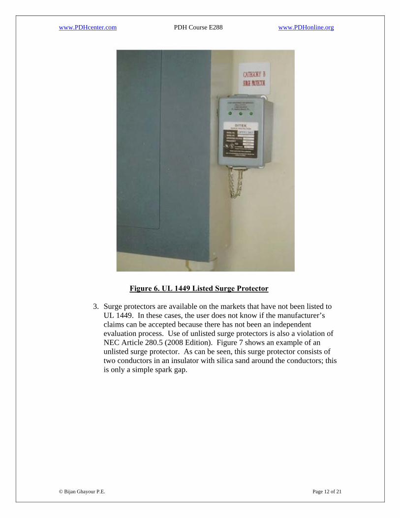
2. The UL 1449 listing process primarily ensures that the surge protector has passed a variety of safety tests. In particular, the UL 1449 fail-safe requirements are intended to address metal oxide varistor (MOV) degradation modes in which an MOV at end of life can conduct continuously, causing overheating. The surge suppression tests listed in UL 1449 are not necessarily representative of actual surges that might be encountered, but UL 1449 listing ensures the surge protector has passed some basic level of qualification. Figure 6 shows a typical listed surge protector properly installed adjacent to a panelboard.
www.PDHcenter.com PDH Course E288 www.PDHonline.org
Figure 6. UL 1449 Listed Surge Protector
© Bijan Ghayour P.E. Page 12 of 21
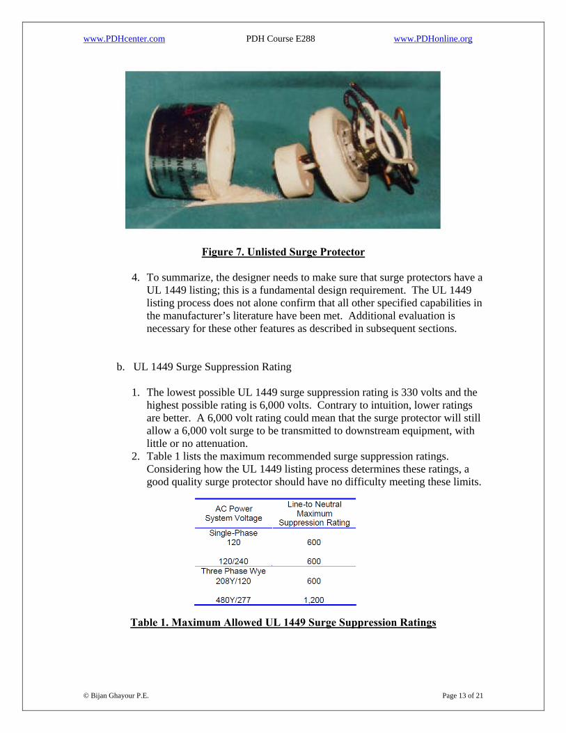
3. Surge protectors are available on the markets that have not been listed to UL 1449. In these cases, the user does not know if the manufacturer’s claims can be accepted because there has not been an independent evaluation process. Use of unlisted surge protectors is also a violation of NEC Article 280.5 (2008 Edition). Figure 7 shows an example of an unlisted surge protector. As can be seen, this surge protector consists of two conductors in an insulator with silica sand around the conductors; this is only a simple spark gap.
www.PDHcenter.com PDH Course E288 www.PDHonline.org
Figure 7. Unlisted Surge Protector
4. To summarize, the designer needs to make sure that surge protectors have a UL 1449 listing; this is a fundamental design requirement. The UL 1449 listing process does not alone confirm that all other specified capabilities in the manufacturer’s literature have been met. Additional evaluation is necessary for these other features as described in subsequent sections.
b. UL 1449 Surge Suppression Rating
1. The lowest possible UL 1449 surge suppression rating is 330 volts and the highest possible rating is 6,000 volts. Contrary to intuition, lower ratings are better. A 6,000 volt rating could mean that the surge protector will still allow a 6,000 volt surge to be transmitted to downstream equipment, with little or no attenuation.
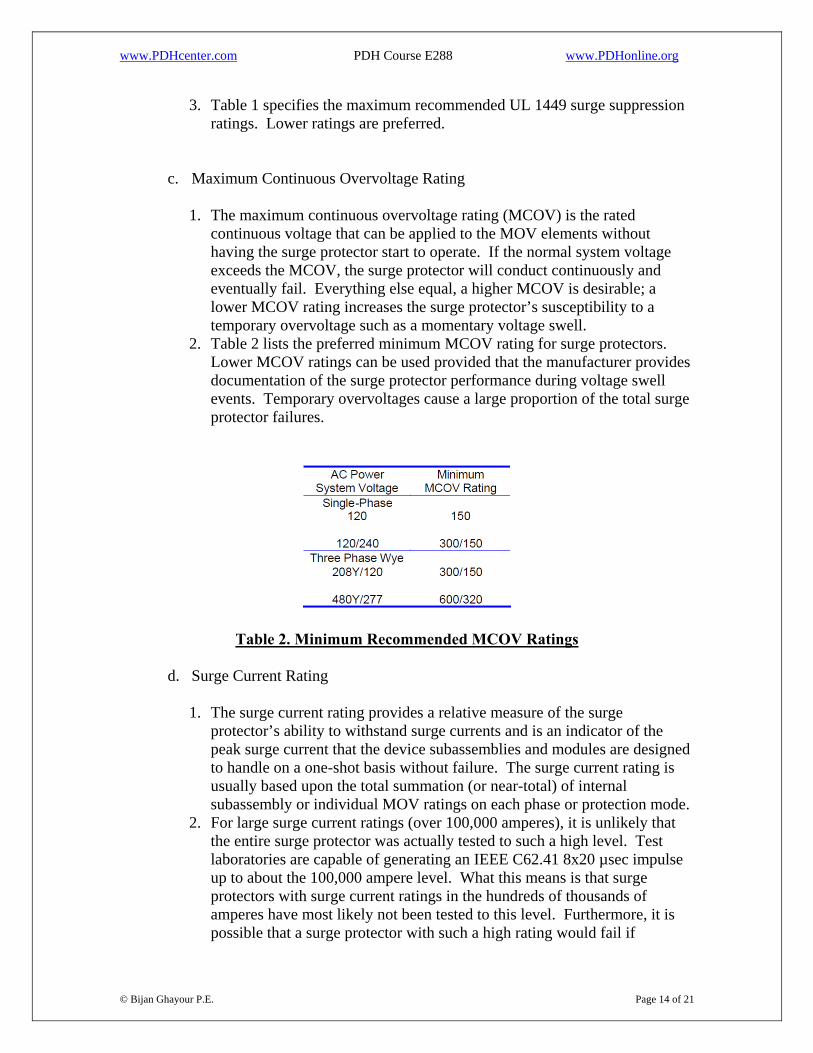
2. Table 1 lists the maximum recommended surge suppression ratings. Considering how the UL 1449 listing process determines these ratings, a good quality surge protector should have no difficulty meeting these limits.
Table 1. Maximum Allowed UL 1449 Surge Suppression Ratings
© Bijan Ghayour P.E. Page 13 of 21
www.PDHcenter.com PDH Course E288 www.PDHonline.org
3. Table 1 specifies the maximum recommended UL 1449 surge suppression ratings. Lower ratings are preferred.
c. Maximum Continuous Overvoltage Rating
1. The maximum continuous overvoltage rating (MCOV) is the rated continuous voltage that can be applied to the MOV elements without having the surge protector start to operate. If the normal system voltage exceeds the MCOV, the surge protector will conduct continuously and eventually fail. Everything else equal, a higher MCOV is desirable; a lower MCOV rating increases the surge protector’s susceptibility to a temporary overvoltage such as a momentary voltage swell.
2. Table 2 lists the preferred minimum MCOV rating for surge protectors. Lower MCOV ratings can be used provided that the manufacturer provides documentation of the surge protector performance during voltage swell events. Temporary overvoltages cause a large proportion of the total surge protector failures.
Table 2. Minimum Recommended MCOV Ratings
d. Surge Current Rating
1. The surge current rating provides a relative measure of the surge protector’s ability to withstand surge currents and is an indicator of the peak surge current that the device subassemblies and modules are designed to handle on a one-shot basis without failure. The surge current rating is usually based upon the total summation (or near-total) of internal subassembly or individual MOV ratings on each phase or protection mode.
© Bijan Ghayour P.E. Page 14 of 21
2. For large surge current ratings (over 100,000 amperes), it is unlikely that the entire surge protector was actually tested to such a high level. Test laboratories are capable of generating an IEEE C62.41 8x20 µsec impulse up to about the 100,000 ampere level. What this means is that surge protectors with surge current ratings in the hundreds of thousands of amperes have most likely not been tested to this level. Furthermore, it is possible that a surge protector with such a high rating would fail if
www.PDHcenter.com PDH Course E288 www.PDHonline.org
subjected to such a high level; circuit board traces, internal fusing, or connecting wire would probably open under the high transient current. Another point to consider with regard to surge current ratings is that the ratings usually assume equal parallel operation of the MOVs, but the nonlinear behavior of MOVs virtually assures that such precise parallel matching is unachievable.
3. For MOV-based designs, the surge current rating provides a relative measure of the amount of MOV surface area that is available for surge protection. As MOVs are subjected to surge voltages, the MOV grain boundaries degrade with time. By including additional MOVs to obtain a higher surge current rating, the surge protector effectively provides an operating and aging margin. In other words, a higher surge current rating can provide a longer operating life. Surge protectors that are rated for hundreds of thousands of amperes of surge current do not actually expect to experience such a high current level. Instead, the higher rating provides assurance that the surge protector can withstand a number of smaller surges, each of which damages MOV grain boundaries by some amount, without experiencing complete failure of the surge protector. By this approach, the surge protector should have a longer life.
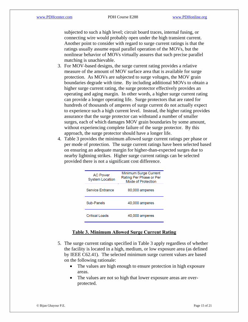
4. Table 3 provides the minimum allowed surge current ratings per phase or per mode of protection. The surge current ratings have been selected based on ensuring an adequate margin for higher-than-expected surges due to nearby lightning strikes. Higher surge current ratings can be selected provided there is not a significant cost difference.
Table 3. Minimum Allowed Surge Current Rating
5. The surge current ratings specified in Table 3 apply regardless of whether the facility is located in a high, medium, or low exposure area (as defined by IEEE C62.41). The selected minimum surge current values are based on the following rationale:
• The values are high enough to ensure protection in high exposure areas.
© Bijan Ghayour P.E. Page 15 of 21
• The values are not so high that lower exposure areas are over-protected.
www.PDHcenter.com PDH Course E288 www.PDHonline.org
• This approach does not force each designer to decide if a given facility is located in a high, medium, or low exposure environment.
e. Repeated Surge Current Withstand Capability
1. The specified surge current ratings are intended to provide an adequate allowance for repeated surges over the life of the surge protector. In addition to the specified surge current ratings, the designer needs to verify that the manufacturer has tested representative surge protectors to the following IEEE C62.41 levels, as a minimum:
2. A minimum of 1,000 operations at ±500 amperes, 100 kilo-Hertz ring wave.
3. A minimum of 1,000 operations at ±3,000 amperes, 8/20 µsec combination wave.
4. A minimum of 40 operations at ±10,000 amperes, 8/20 µsec combination wave.
5. A minimum of 1 operation at ±20,000 amperes, 8/20 µsec combination wave (one in each polarity).
f. Modes of Protection
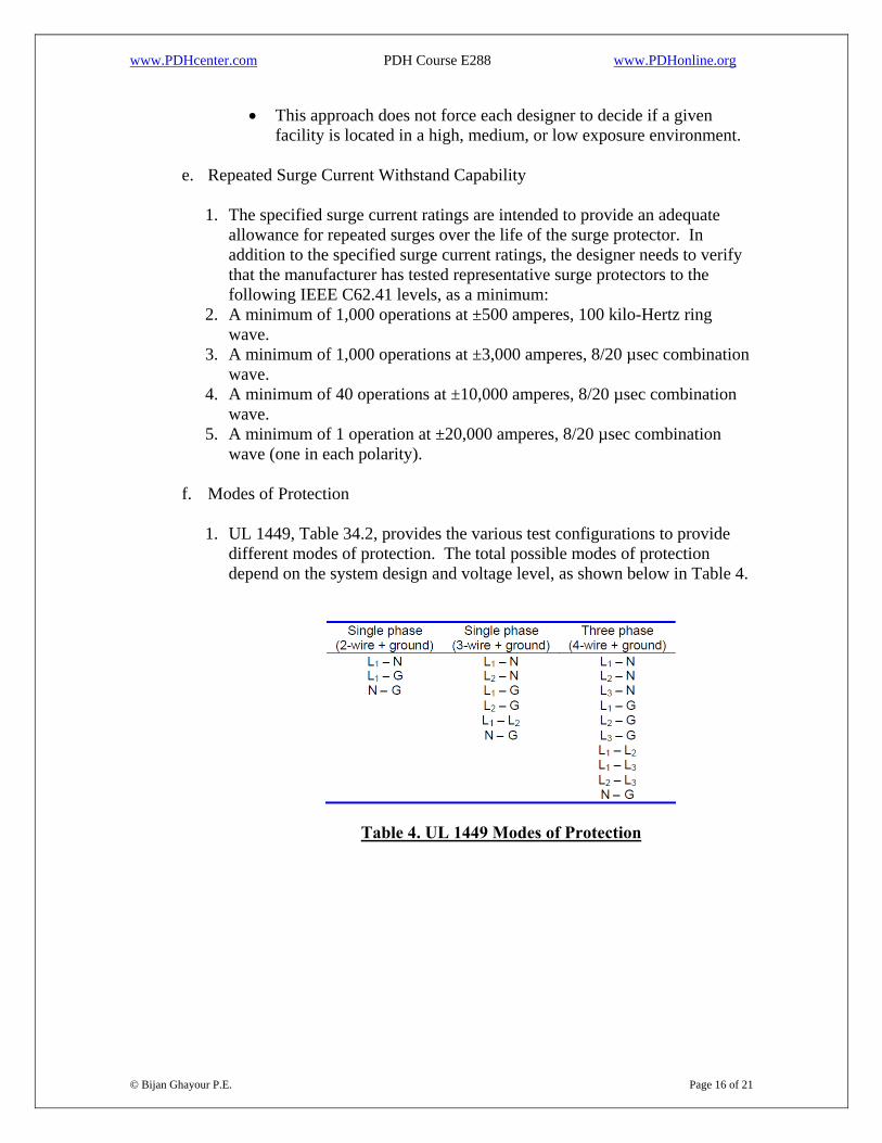
1. UL 1449, Table 34.2, provides the various test configurations to provide
different modes of protection. The total possible modes of protection depend on the system design and voltage level, as shown below in Table 4.
Table 4. UL 1449 Modes of Protection
© Bijan Ghayour P.E. Page 16 of 21
www.PDHcenter.com PDH Course E288 www.PDHonline.org
2. Wye Connections
i. For single phase and three phase wye connected systems, the following modes of protection are recommended: a. Each phase to neutral (L – N) b. Neutral to ground (N – G).
ii. Phase to ground (L – G) protection will be important if the grounding system is of poor quality or in other countries where neutral and ground are not connected. By protecting both the neutral and ground paths, any differences in potential between the two points will still be protected against surge events.
iii. Phase to phase (L – L) protection is not needed for wye-connected systems provided that the other modes of protection are provided.
3. Delta Connections. Provide the following modes of protection:
i. Phase to phase (L-L)
ii. Phase to ground (L-G)
g. Internal Fusing
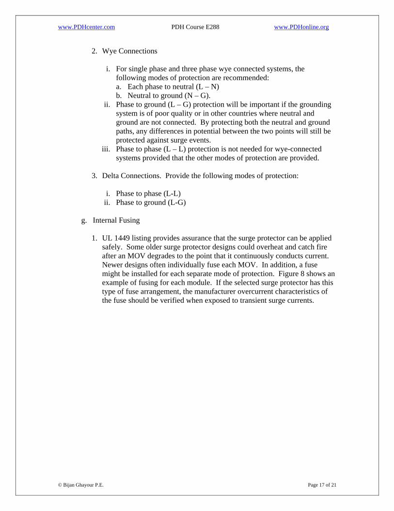
1. UL 1449 listing provides assurance that the surge protector can be applied safely. Some older surge protector designs could overheat and catch fire after an MOV degrades to the point that it continuously conducts current. Newer designs often individually fuse each MOV. In addition, a fuse might be installed for each separate mode of protection. Figure 8 shows an example of fusing for each module. If the selected surge protector has this type of fuse arrangement, the manufacturer overcurrent characteristics of the fuse should be verified when exposed to transient surge currents.
© Bijan Ghayour P.E. Page 17 of 21
www.PDHcenter.com PDH Course E288 www.PDHonline.org
Figure 8. Example of Internally Fused Surge Protector
h. Installation Capability
1. Surge protectors covered by this course should normally be of the parallel type. The surge protector size and installation method are important evaluation considerations. If the surge protector enclosure is over-sized, it might not fit near the required location, thereby causing the lead length of the connecting conductors to be excessive, which increases the let-through voltage.
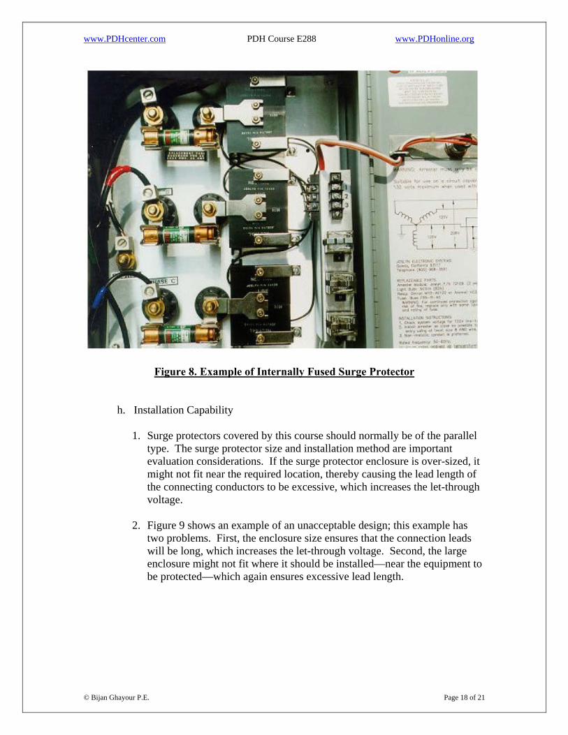
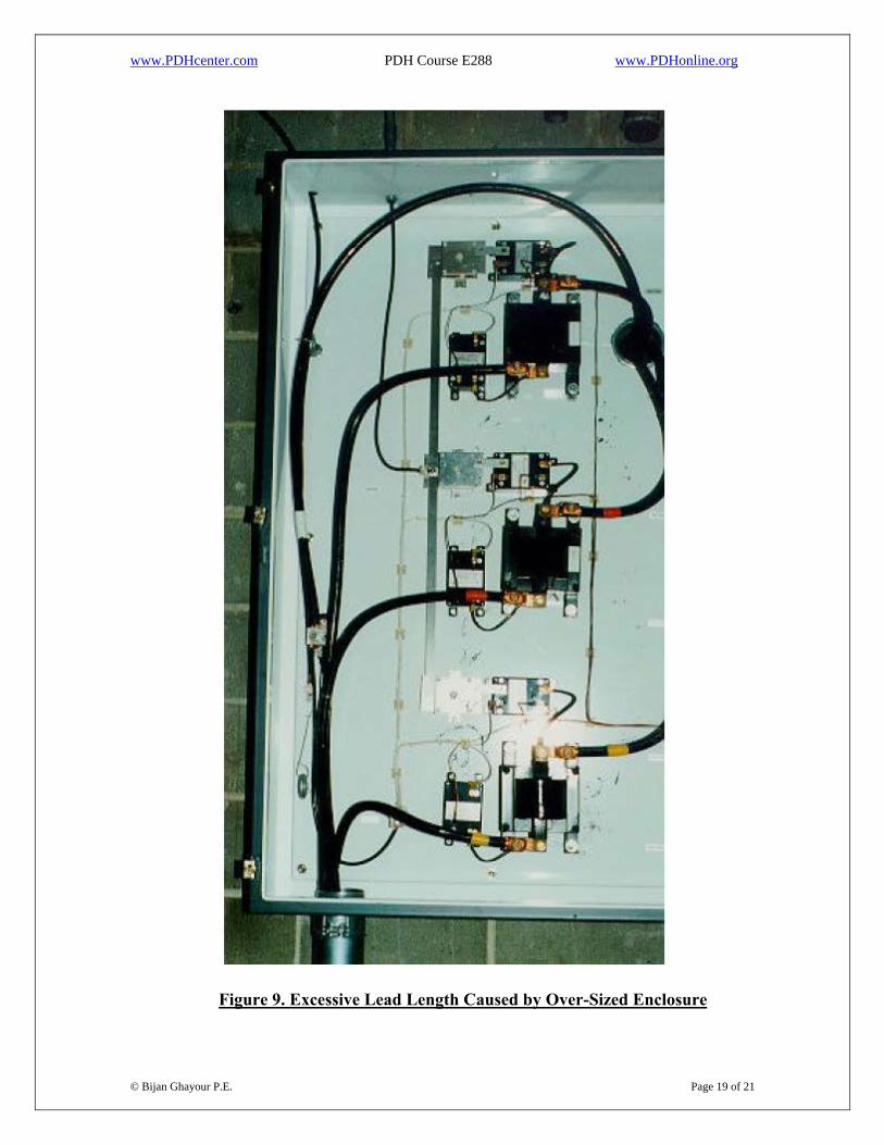
2. Figure 9 shows an example of an unacceptable design; this example has
two problems. First, the enclosure size ensures that the connection leads will be long, which increases the let-through voltage. Second, the large enclosure might not fit where it should be installed—near the equipment to be protected—which again ensures excessive lead length.
© Bijan Ghayour P.E. Page 18 of 21
www.PDHcenter.com PDH Course E288 www.PDHonline.org
Figure 9. Excessive Lead Length Caused by Over-Sized Enclosure
© Bijan Ghayour P.E. Page 19 of 21
www.PDHcenter.com PDH Course E288 www.PDHonline.org
i. Warranty
1. A minimum 5-year full-replacement warranty is recommended. Longer warranty intervals are desirable.
j. Price
1. The previous specification criteria attempt to provide an adequate
minimum level of surge protector performance. Given this approach, the lowest bid can be used provided that the selected supplier confirms the required performance attributes listed in paragraphs E-2.a through E-2.i.
3. Performance Specifications That Are Not Important
a. Introduction
1. The previous section listed the important surge protection attributes. This section discusses performance attributes that either are less important or are possibly misunderstood because of inconsistent terminology in the industry.
b. Clamping Voltage
1. References to clamping voltage should be disregarded unless it can be
confirmed that the meaning is equivalent to let-through voltage as defined in this manual. Depending on its use, the clamping voltage can be the voltage at which the surge protector starts to operate. In this case, the clamping voltage does not provide adequate information regarding the actual let-through voltage. Manufacturers that provide only a clamping voltage might be disguising poor let-through voltages. UL 1449 listing establishes a standardized suppression voltage rating that can be used for evaluation purposes. The UL 1449 suppression voltage rating should be compared to the stated clamping voltage to identify any significant differences. If necessary, the manufacturer needs to provide a copy of the UL listing test file to assure that clamping voltage is not inappropriately stated.
c. Response Time
1. Manufacturers advertise response time but the meaning is not always clear.
Response time is not important; let-through voltage is important. If the surge protector response time is slow, the let-through voltage will be high.
© Bijan Ghayour P.E. Page 20 of 21
www.PDHcenter.com PDH Course E288 www.PDHonline.org
d. Joules Rating
1. The joules rating (sometimes referred to as surge energy capability) is not
an important performance attribute and is frequently misunderstood. If the surge protector is listed to UL 1449 and has demonstrated acceptable operational cycling, the surge protector will have an acceptable energy dissipation capability.
e. Sine Wave Tracking
1. The suppression of the surge voltage throughout the sine wave has been referred to as sine wave tracking and it can provide an added level of protection for sensitive loads. The term sine wave tracking is not used in industry standards, it is not confirmed as an attribute by UL 1449, and its meaning does not appear to have an industry-accepted definition. Sine wave tracking is not considered a design requirement for surge protectors. Manufacturers that market sine wave tracking as a design feature are claiming that the surge protector will provide a certain level of suppression throughout the sine wave. This suppression is usually achieved by installing capacitors. If sine wave tracking is a feature desired by the user, the manufacturer needs to provide certified test data that demonstrates this capability. The test data should include surge applications at different points on the sine wave.
© Bijan Ghayour P.E. Page 21 of 21
www.PDHcenter.com PDH Course E288 www.PDHonline.org
Appendix A
SURGE PROTECTION LET-THROUGH BY EXCESSIVE LEAD LENGTH
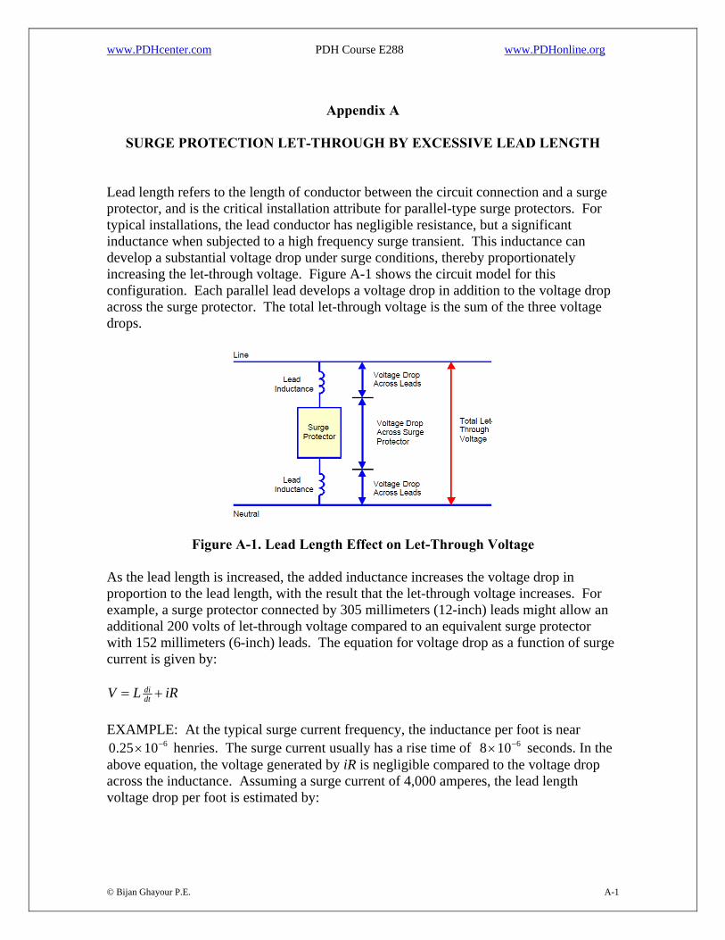
Lead length refers to the length of conductor between the circuit connection and a surge protector, and is the critical installation attribute for parallel-type surge protectors. For typical installations, the lead conductor has negligible resistance, but a significant inductance when subjected to a high frequency surge transient. This inductance can develop a substantial voltage drop under surge conditions, thereby proportionately increasing the let-through voltage. Figure A-1 shows the circuit model for this configuration. Each parallel lead develops a voltage drop in addition to the voltage drop across the surge protector. The total let-through voltage is the sum of the three voltage drops.
Figure A-1. Lead Length Effect on Let-Through Voltage
As the lead length is increased, the added inductance increases the voltage drop in proportion to the lead length, with the result that the let-through voltage increases. For example, a surge protector connected by 305 millimeters (12-inch) leads might allow an additional 200 volts of let-through voltage compared to an equivalent surge protector with 152 millimeters (6-inch) leads. The equation for voltage drop as a function of surge current is given by:
iRLV dtdi +=
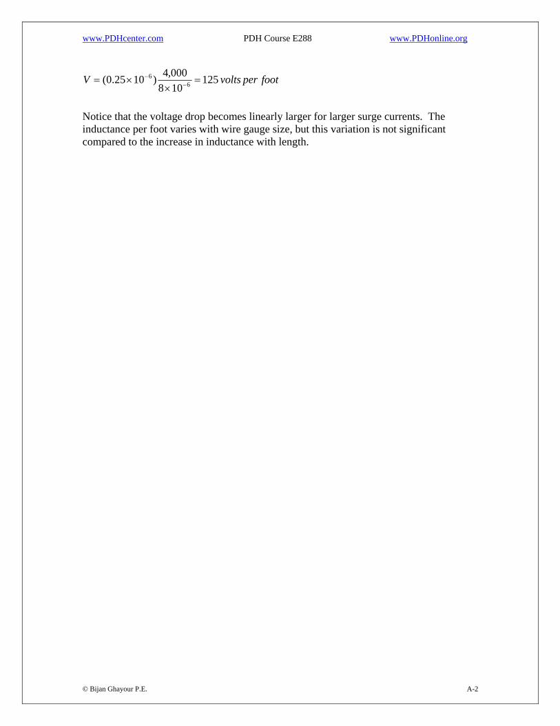
EXAMPLE: At the typical surge current frequency, the inductance per foot is near
henries. The surge current usually has a rise time of seconds. In the above equation, the voltage generated by iR is negligible compared to the voltage drop across the inductance. Assuming a surge current of 4,000 amperes, the lead length voltage drop per foot is estimated by:
61025.0 −× 6108 −×
© Bijan Ghayour P.E. A-1
www.PDHcenter.com PDH Course E288 www.PDHonline.org
footpervoltsV 125108000,4)1025.0( 6
6 =×
×= −−
© Bijan Ghayour P.E. A-2
Notice that the voltage drop becomes linearly larger for larger surge currents. The inductance per foot varies with wire gauge size, but this variation is not significant compared to the increase in inductance with length.