Embed Size (px)
Citation preview
SURGICALMANUAL
2
CONTENTS
1.0 BASIC INFORMATION FOR SURGICAL PROCEDURES 5
2.0 THE NEODENT IMPLANT SYSTEM 5
2.1 Overview 5
2.2 CM Implant 6
2.3 WS 7
2.4 Facility 8
3.0 IMPLANT DESIGNS 9
3.1 Surface 9
3.1.1 Neoporos 9
3.1.2 Acqua 10 3.2 Implant Options 11
3.2.1 Drive CM 11
3.2.2 Titamax CM EX 11
3.2.3 Titamax CM 11
3.2.4 Alvim CM 12
3.2.5 Facility 12
3.2.6 Titamax WS 12
3.3 Options of thread according to the implant design 13
4.0 INDICATIONS AND CONTRAINDICATIONS 15
5.0 PRE-OPERATIVE PLANNING 16
5.1 Implant positioning and peri-implant tissue 16
5.1.1 Mesiodistal Positioning of the implant 17
5.1.1.1 Examples of single tooth gaps 18

3
5.1.1.2 Examples of multiple tooth gaps 19
5.1.2 Buccal-lingual implant position 21
5.1.3 Apical coronal implant position 21
5.2 Planning aids 22
5.2.1 Space Planning Instrument as a diagnosis and help for implant placement 22
5.2.2 Direction Indicator pins for the diagnosis of adjacent bone 23
5.2.3 Surgical drill template or guide 25
5.2.4 X-ray templates 26
5.2.5 Softwares for implant planning 26
6.0 SURGICAL PROCEDURES 27
6.1 Implant bed preparation 27
6.1.1 Basic implant bed preparation 27
6.1.1.1 For conical Alvim and Drive implants 29
6.1.1.2 For cylindrical Titamax implants 30
6.1.1.3 For narrow Facility implants 34
6.1.2. Fine implant bed preparation 37
6.1.2.1. Pilot Drill 37
6.1.2.2. Tap Drill 37
6.1.2.3. Example of fine implant bed preparation 38
6.2. Neodent implant packaging 40
6.1.3 Options for drilling 40
6.3. Placing the implant 43
6.3.1. Place the implants with the contra angle 43
6.3.2. Place the implants by hands 44
6.3.3. Finalize the implant positioning with the wrench 45

4
6.4. Soft tissue management 45
6.4.1 Two stage/ submucosal healing 45
6.4.2 Transmucosal healing: One stage or Immediate loading 49
6.4.2.1. Transmucosal healing: One stage 50
6.5 Overview of the healing abutments 51
6.5.1 Overview of the CM Abutments and corresponding Healing Caps 52
7. HEALING PHASE 54
8. ABUTMENT TRY IN KIT 54
9. PROSTHODONTICS GENERAL GUIDELINES 55
10. NEODENT KITS 57
10.1 Sterilization 57
10.2 Cleaning and care of instruments 57
BIBLIOGRAPHIC REFERENCES 58
1.0 BASIC INFORMATION FOR SURGICAL PROCEDURES
The Modern Implantology era, based over clinical results on osseointegration, was originally published
on English based journals in 1977(1). Since then Dentistry had important changes and the treatment plan
of a patient today usually offer implant retained and/or supported prosthesis as an affordable and reliable
solution. The number of oral implants placed are rapidly increasing over the years(2, 3) and this treatment
concept requires specific skills and knowledge, as the surgeon’s learning curve, that are relevant for the
results(4). Based on this facts the present guide aims to provide to dental practioners and specialists basic
information and steps regarding the planning, surgical procedures and options of treatment.
This guide does not replace the instructions for use (IFU) of each product, which can be found in
our website: www.neodent.com.br.
2.1 Overview
2.0 THE NEODENT IMPLANT SYSTEM
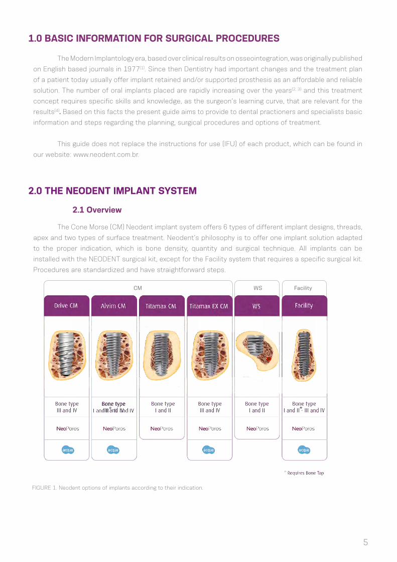
The Cone Morse (CM) Neodent implant system offers 6 types of different implant designs, threads,
apex and two types of surface treatment. Neodent’s philosophy is to offer one implant solution adapted
to the proper indication, which is bone density, quantity and surgical technique. All implants can be
installed with the NEODENT surgical kit, except for the Facility system that requires a specific surgical kit.
Procedures are standardized and have straightforward steps.
FIGURE 1. Neodent options of implants according to their indication.
CM WS Facility
5
6
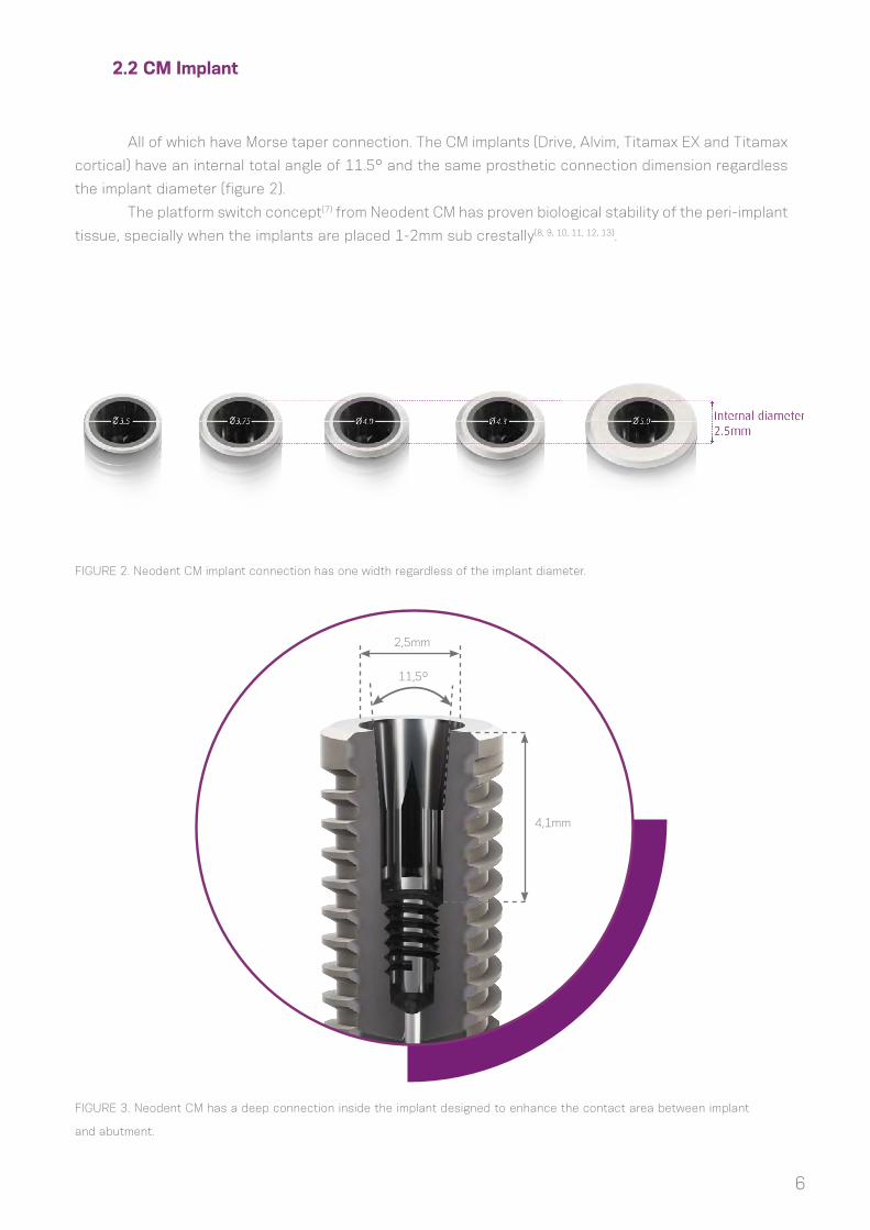
All of which have Morse taper connection. The CM implants (Drive, Alvim, Titamax EX and Titamax
cortical) have an internal total angle of 11.5° and the same prosthetic connection dimension regardless
the implant diameter (figure 2).
The platform switch concept(7) from Neodent CM has proven biological stability of the peri-implant
tissue, specially when the implants are placed 1-2mm sub crestally(8, 9, 10, 11, 12, 13).
FIGURE 2. Neodent CM implant connection has one width regardless of the implant diameter.
FIGURE 3. Neodent CM has a deep connection inside the implant designed to enhance the contact area between implant
and abutment.
2,5mm
11,5º
4,1mm
2.2 CM Implant

7
FIGURE 4. Internal index as a hexagon
created to surgically drive the implant and
to proceed with the implant impression
during the prosthetic phase.
The Neodent conical connection has an internal hexagon as an index in its bottom called Exact.
Exact is used for implant surgical placement and the repositioning of prosthetic parts when working at the
implant level.
WS (short implants) is a complementary line of cone Morse implants, suitable for special areas. WS
Implants also feature an internal angle os 11.5°, but different internal diameter and length. Therefore, a
special line of abutments is required when working with these implants. They are indicated as an alternative
for posterior free ended partially edentulous.
FIGURE 5. WS implant connections are similar and compatible.
3,0mm
2.3 WS

8
FIGURE 6. Facility is the narrowest implant
offered in the system and its abutments are
placed through friction.
TABLE 1. Offer of diameters according to the implant design.
The system has a full portfolio, adapted to the bone density/quality and patients needs.
Facility Implants also have a cone Morse connection, but with an internal angle of 5°. They are
the narrowest implants offered by Neodent and their abutments are placed through friction. Their use is
indicated to the upper lateral incisors and lower incisors areas.
Titamax
Titamax EX
Alvim
Drive
WS
Facility
Implant
Diameter
2.9 3.5 3.75 4.0 4.3 5.0 6.0
TABLE 2. Options of length according to the implant design.
* Available with Neoporos surface
Titamax*
Titamax EX
Alvim
Drive
WS*
Facility
Implant
Lenght
5 6 97 10 12 14 1611 13 15 17 18 1911,58
*
2.4 Facility

3.0 IMPLANT DESIGNS
Neodent CM implants are classified according to their macro design, thread features, apex and
microroughness.
APEX
PROS
THET
ICCO
NNE
CTIO
NIM
PLAN
TBO
DY
CM
Drive Titamax Alvim
AlvimTitamaxDrive
9
FIGURE 7. General feature of the Neodent implants.
Titamax EX
Neodent implants are offered in two types of surface treatment as presented below. The decision
about each surface is driven by the clinical indication.
Neoporos is a special process created for the Neodent implant surface. Firstly the roughness is
obtained through sandblasting, where the size of particles and the pressure are adapted to the implant
design. Posteriorly blasting, the implants are acid etched in specific conditions. Figure 8 represents this
procedure.
3.1 Surface
3.1.1 Neoporos
FIGURE 8. Physical manufacturing process of Neodent Treatment surface
MachinedSa= 0.26 µm
Sand blastedSa= 0.67 µm
Sand blasted + Acid etchedSa= 0.93 µm

10
3.1.2 Acqua
Acqua is a hydrophilic implant with the titanium surface having the valence shell changed.
The physical process from Neoporos is performed over the implants, however Acqua is manufactured
in a especial area of the Neodent production where all implants are packaged and stored in a liquid
environment, avoiding contact with the atmosphere. This isolation results in wettability (presenting
contact angle <5°) and an active physicochemical surface (with positive ions).
Implants with Acqua surface are indicated for implant placement in grafted areas, combined with
grafting procedures, post extraction and sites of poor bone density(17,18).
Surface Comparison
Hydrophobic Surface (conventional). Acqua Hydrophilic Surface.
FIGURE 9. Micro (0.3-1.3 µm) and macro (15-30 µm) structure for Acqua & Neoporos
FIGURE 10. Confocal laser scanning microscopy in the thread region(15).
Oxygen O
Titanium Ti
Nitrogen N
Note: XPS measurements on Neoporos and Acqua Surfaces
Neoporos (Atom%) Acqua (Atom%)
Carbon C
55.9 ± 0.9 59.3 ± 0.2
0.4 ± 0.6 0.6 ± 0.4
21.1 ± 0.7 22.7 ± 0.3
22.7 ± 2.0 15.3 ± 1.0

11
3.2 Implant Options
(1) Offered as Acqua or Neoporos surfaces; (2) Tapered implant with internal
conical body; (3) Cervical conicity with microthreads; (4) Main threads are square
shaped with a 2.2mm thread pitch; (5) Double threaded implant; (6) Reverse cutting
chambers distributed across the implant body; (7) Bottom thread with sharp edge;
(8) Rounded apex; (10) Indicated for bone types III and IV and implant immediate
placement post-extraction; (11) Same prosthetic connections for all diameters; (12)
Implant should be positioned 1-2mm below bone level for better results (8, 9, 10, 11, 12, 13);
(13) Drill speed: 500 - 800 rpm; (14) Implant insertion speed: 30 rpm;
(15) Maximum torque for placement 60 N.cm.
(1) Offered as Acqua or Neoporos surfaces; (2) Parallel wall (cylindrical) implant;
(3) Triangular (or pyramidal) threads with 1.2 mm of thread pitch; (4) Double threaded
implant; (5) Implant apex adaptad to be inserted in a 2.0mm osteotomy; (6) Indicated for
bone types III and IV and for areas with narrow bone areas where under preparation
is indicated; (7) Contra indicated for immediate placement post extraction; (8) Same
prosthetic connection for all implant diameters; (9) The implant cervical diameter is
the same as the body diameter; (10) Implant should be positioned 1-2mm below bone
level for better results (19); (11) Drill speed: 500 - 800 rpm; (12) Implant insertion speed:
30 rpm; (13) Maximum torque for placement 60 N.cm.
(1) Only offered as NeoPoros surface; (2) Parallel wall (cylindrical) implants;
(3) Triangular (or pyramidal) threads with 1.2 mm of thread pitch; (4) Double threaded
implant; (5) Self tapping chambers; (6) Indicated for bone types I and II or grafted
areas as bone block; (6) Same prosthetic connection for all implant diameters; (7) The
implant cervical diameter is the same as the body diameter; (8) Final pilot drills are
highly recommended to be used as the implant should be positioned 1-2mm below
bone level for better results(19); (8) No tap is needed during placement; (9) Osteotomy
drill speed: 800- 1200 rpm; (10) Implant insertion speed: 30 rpm; (10) Maximum torque
for placement 60 N.cm
3.2.1 Drive CM
3.2.2 Titamax CM EX
3.2.3 Titamax CM

12
(1) Offered as Acqua or Neoporos surfaces; (2) Tapered implant; (3) Trapezoidal
threads with 1.2 mm of thread pitch; (4) Double threaded implant; (5) Conical apex with
low active chambers designed to optimize secondary stability; (6) Indicated for bone
types III and IV and implant immediate placement post-extraction; (7) Tap is needed
if indicated for bone types I and II; (8) Same prosthetic connection for all implant
diameters; (9) The implant cervical diameter is the same as the body diameter; (10)
Final pilot drills are highly recommended to be used in bone types I and II; (11) Implant
should be positioned 1-2mm below bone level for better results(19); (12) Drill speed:
800- 1200 rpm for bone type I and II; (13) Drill speed: 500 - 800 rpm for bone type III
and IV; (14) Implant insertion speed: 30 rpm; (15) Maximum torque for placement 60
N.cm.
3.2.4 Alvim CM
(1) Offered as Acqua or Neoporos surfaces; (2) narrow implant with 2.9mm
in diameter with a pure cone Morse frictional lock connection; (3) Double threaded
implant; (4) Recommended for lateral upper incisors and lower incisors; (5) Indicated for
bone types I, II, III and IV; (6) Tap is needed if used in bone types I and II; (7) The implant
cervical diameter is the same as the body diameter; (8) Implant could be positioned
1-2mm below bone level when possible; (9) Requires exclusive instruments and line of
prosthetic components; (10) Drill speed: 500 a 800 rpm; (11) Implant insertion speed:
30 rpm; (12) maximum torque for placement 45 N.cm.
3.2.5 Facility
(1) Only offered with Neoporos surface; (2) Parallel wall (cylindrical); (3) Triangular
(or pyramidal) threads with 0.6 mm of thread pitch; (4) Single threaded implant due
to the short implant length; (5) Apex with self tapping chambers; (6) Indicated for
bone types I and II; (7) Alternative for posterior free ended partially edentulous; (8)
The implant cervical diameter is the same as the body diameter; (9) Final pilot drills
are recommended depending on the implant final positioning; (10) Implant could be
positioned 1 mm below bone level when possible; (11) Requires exclusive instruments
and line of prosthetic components; (12) Pre-mounted fixture; (13) Osteotomy drill
speed : 200 a 300 rpm; (14) Implant insertion speed: 30 rpm; (15) Maximum torque for
placement 60 N.cm
3.2.6 Titamax WS
13
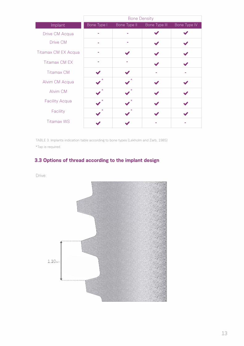
TABLE 3. Implants indication table according to bone types (Lekholm and Zarb, 1985)
*Tap is required.
Drive CM Acqua
Implant
Bone Density
Bone Type I Bone Type II Bone Type III Bone Type IV
Drive CM
Titamax CM EX Acqua
Titamax CM EX
Titamax CM
Alvim CM Acqua
Alvim CM
Facility Acqua
Facility
Titamax WS
* *
-
-
-
- -
-
-
- -
--
* *
* *
* *
3.3 Options of thread according to the implant design
Drive:

14
Alvim:
Titamax:
15
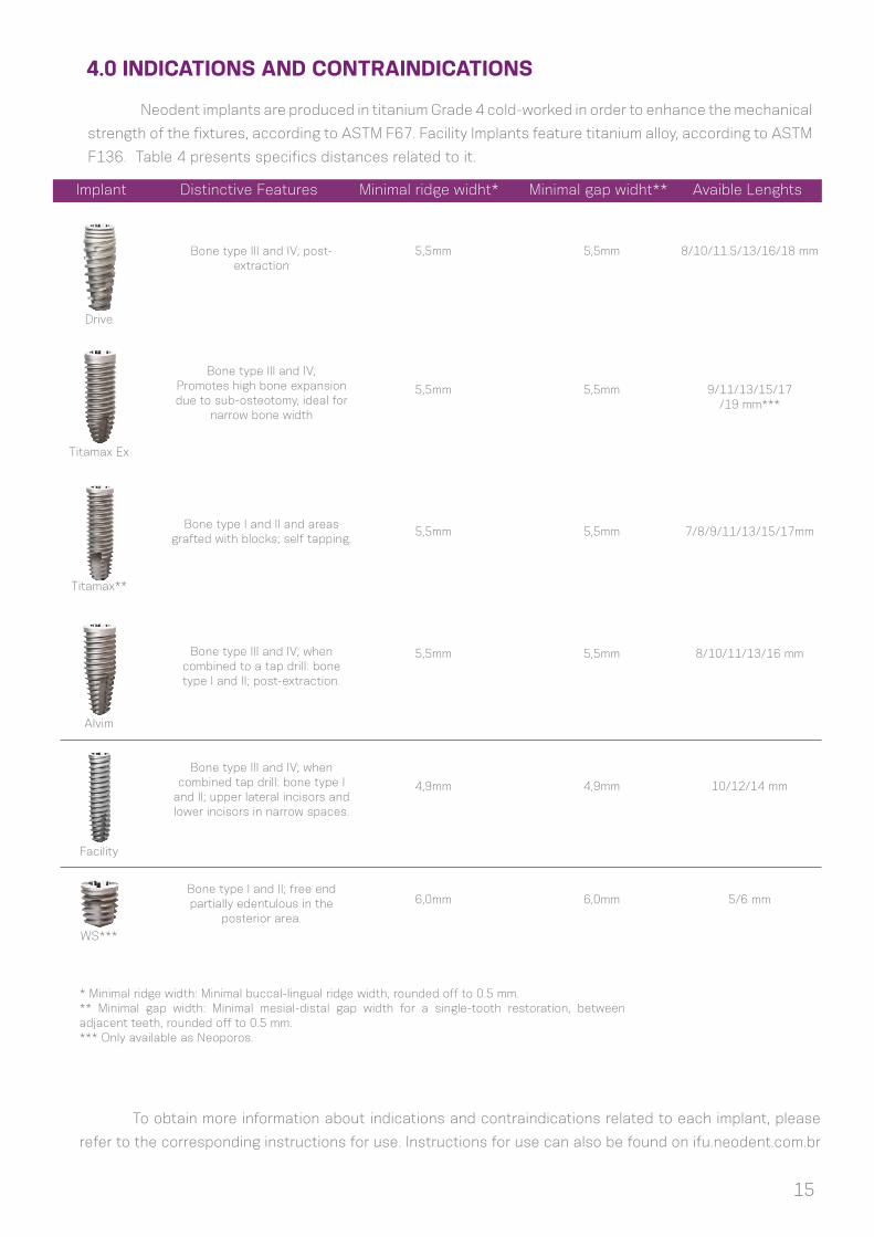
4.0 INDICATIONS AND CONTRAINDICATIONS
Neodent implants are produced in titanium Grade 4 cold-worked in order to enhance the mechanical
strength of the fixtures, according to ASTM F67. Facility Implants feature titanium alloy, according to ASTM
F136. Table 4 presents specifics distances related to it.
To obtain more information about indications and contraindications related to each implant, please
refer to the corresponding instructions for use. Instructions for use can also be found on ifu.neodent.com.br
* Minimal ridge width: Minimal buccal-lingual ridge width, rounded off to 0.5 mm.** Minimal gap width: Minimal mesial-distal gap width for a single-tooth restoration, between adjacent teeth, rounded off to 0.5 mm.*** Only available as Neoporos.
Implant Distinctive Features Minimal ridge widht* Minimal gap widht** Avaible Lenghts
Bone type III and IV; post-extraction
5,5mm
5,5mm
5,5mm
5,5mm
4,9mm
6,0mm
5,5mm 8/10/11.5/13/16/18 mm
5,5mm 9/11/13/15/17/19 mm***
5,5mm 7/8/9/11/13/15/17mm
5,5mm 8/10/11/13/16 mm
4,9mm 10/12/14 mm
6,0mm 5/6 mm
Bone type III and IV;Promotes high bone expansion due to sub-osteotomy, ideal for
narrow bone width
Bone type I and II and areas grafted with blocks; self tapping.
Bone type III and IV; when combined to a tap drill: bone type I and II; post-extraction.
Bone type I and II; free end partially edentulous in the
posterior area.
Bone type III and IV; when combined tap drill: bone type I
and II; upper lateral incisors and lower incisors in narrow spaces.
Drive
Titamax Ex
Titamax**
Alvim
Facility
WS***

16
5.0 PRE-OPERATIVE PLANNING
5.1 Implant positioning and peri-implant tissue
The implant positioning is the key to obtain the correct prosthetic restoration, and is the basis
for the surgical planning. An adequate communication amongst the patient, dentist, surgeon and lab
technician is essential for reaching the desired prosthetic result.
To establish the correct planning, with the correct spatial position, choosing the ideal implant
design (diameter and length), number and distribution of implants, it is recommended to:
- Perform a wax-up on the patient’s study cast;
- Define the edentulous space to be restored;
- Define the type of superstructure;
- Do CT scan and radiographic exams.
The wax-up can then be used to fabricate the radiographic and/or surgical template, and be used
as a temporary restoration. Physiological occlusion is determinant to the implant success in short and long
term. Immediate loading procedures couldn’t be performed in patients with problems in occlusion.
Notes: The implant abutments should always be loaded axially, and the long axis of the implant aligned with the cusps of the opposing teeth. Extreme cusp formation should be avoided, since it may lead to unphysiological overloading.
The diameter, type, position and number of implants should be individually decided for each
patient, taking into account anatomy and the prosthetic space, bad positioned or angled teeth should be
considered and analyzed. The recommendations presented here should be considered as basic guidelines
for correct biological healing, adequate restorations and that the patient may have the conditions for
efficient hygiene of the area. The restoration design has a strong impact over occlusion and hygiene and
it must be taken in consideration.
The final response of the hard and soft tissues is highly influenced by the position of the abutment,
therefore the tri-dimensional positioning of the implant needs to be studied, being these:
• Mesiodistal
• Bucco lingual
• Apical Coronal

17
5.1.1 Mesiodistal Positioning of the implant
The available mesiodistal bone is an important factor when choosing the implant diameter and
quantity. It is the distance between implant to teeth and implant to implant when multiple implants are
required. The reference point is to measure the larger mesiodistal width of the implant, usually in the cervical
area. Generally implants require a minimum of adjacent bone of 1.5mm around it. The distances shown here
are rounded off minimum 0.5mm of bone.
The basic rules to be followed are:
Rule 1
Ideally, the distance of CM implants to
adjacent teeth is at least 1.5mm between
the implant widest portion and the teeth,
both on the mesial and distal aspects.
Rule 2
As implants requires at least 1.5mm of
adjacent bone, the distance to other
implants is minimum 3mm.
18
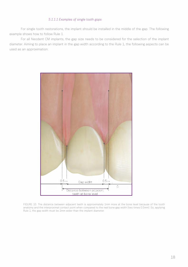
5.1.1.1 Examples of single tooth gaps
For single tooth restorations, the implant should be installed in the middle of the gap. The following
example shows how to follow Rule 1.
For all Neodent CM implants, the gap size needs to be considered for the selection of the implant
diameter. Aiming to place an implant in the gap width according to the Rule 1, the following aspects can be
used as an approximation:
FIGURE 10. The distance between adjacent teeth is approximately 1mm more at the bone level because of the tooth anatomy and the interproximal contact point when compared to the real bone gap width (two times 0.5mm). So, applying Rule 1, the gap width must be 2mm wider than the implant diameter.
19
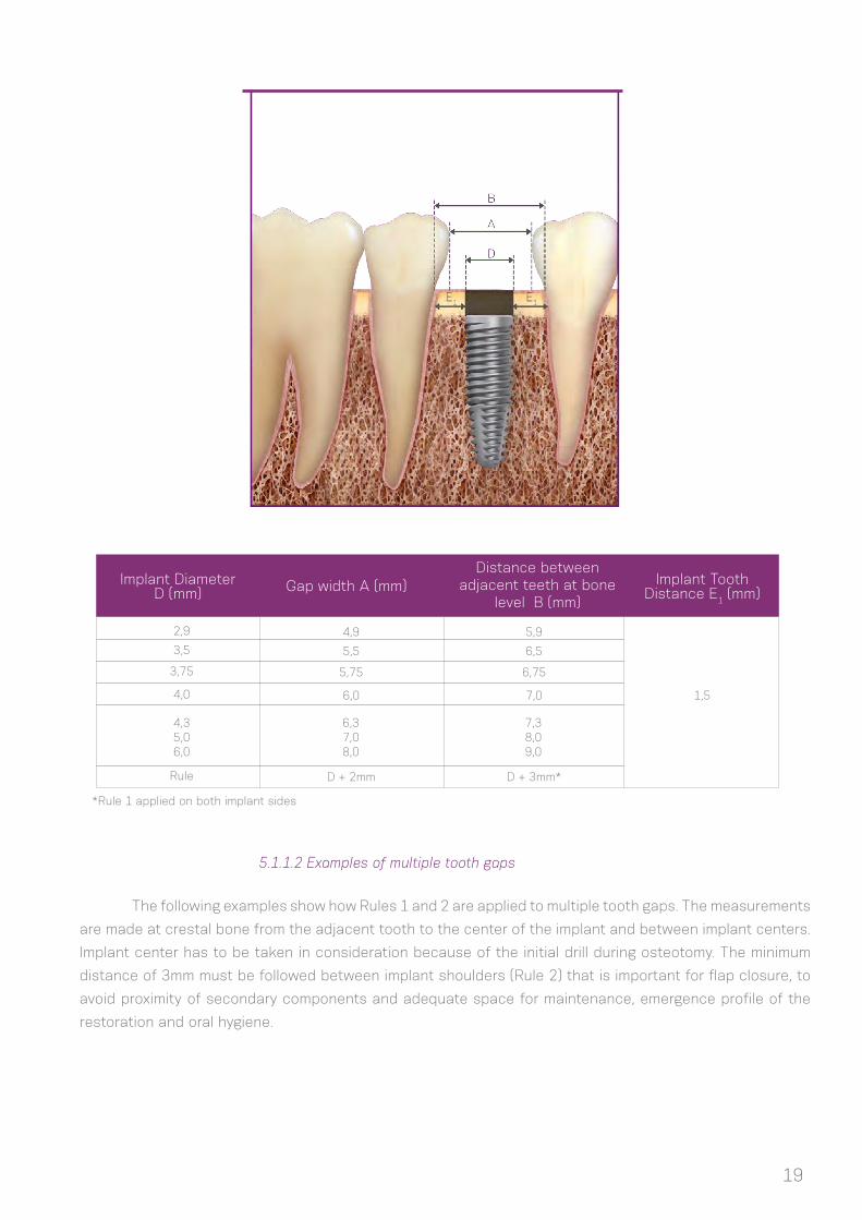
Implant Diameter D (mm)
Implant Tooth Distance E1 (mm)Gap width A (mm)
Distance between adjacent teeth at bone
level B (mm)
4,9
5,5
5,75
6,0
D + 2mm
5,9
6,5
6,75
7,0 1,5
D + 3mm*
2,9
3,5
3,75
4,0
4,35,06,0
6,37,08,0
7,38,09,0
Rule
*Rule 1 applied on both implant sides
5.1.1.2 Examples of multiple tooth gaps
The following examples show how Rules 1 and 2 are applied to multiple tooth gaps. The measurements
are made at crestal bone from the adjacent tooth to the center of the implant and between implant centers.
Implant center has to be taken in consideration because of the initial drill during osteotomy. The minimum
distance of 3mm must be followed between implant shoulders (Rule 2) that is important for flap closure, to
avoid proximity of secondary components and adequate space for maintenance, emergence profile of the
restoration and oral hygiene.

20
Implant Diameter D1 (mm)
Implant Diameter D2 (mm)
A B C L
2,9
3,5
3,75
4,0
4,3
5,0
6,0
2,9
3,5
3,75
4,0
4,3
5,0
6,0
3,0
3,3
3,4
3,5
3,7
4,0
4,5
5,9
6,5
6,8
7,0
7,3
8,0
9,0
3,0
3,3
3,4
3,5
3,7
4,0
4,5
11,8
13
13,5
14
14,6
16
18
Normally clinical cases have different Gaps and then
D1/D2 can be different in order to adapt the implants to every
situation. Looking for a simpler rule, the dentist has to take in
consideration that every implant requires a minimum of 1.5 mm
of adjacent bone, regardless of the implant diameter. So during
the planning it must be considered that independently of the
implant diameter, it is important to have the minimum of 1.5 mm
of mesial and distal peri implant bone.
1,5mm
Implant Tooth Distance E2 (mm)
3,0

21
5.1.2 Buccal-lingual implant position
5.1.3 Apical coronal implant position
The facial and palatal bone layer must be at least 1mm in thickness so as to ensure stable hard and
soft tissue conditions. The minimum buccal-lingual width of each implant diameter is shown in table 4. Within
this limitation, a restoration-driven buccal-lingual implant position and axis should be chosen so that better
restorations are obtained. Also, the surgeon needs to know if the plan is to do a screw or cement-retained
prosthesis.
Caution: Techniques for bone augmentation are highly advisable for ridges where the orofacial bone wall is 1mm
or less or where there is bone missing on one of the sides. These procedures should be conducted only by dentists with
advanced experience in grafted bone regeneration (GBR).
CM Neodent implants were designed for a
2mm sub-crestal positioning in order to optimize
stability of hard and soft tissues and also for better
aesthetic results of the restorations, especially in
the front area(6,7,8,9,10,12).
In a scalloped situation, place the implant
at the bone level according to the inner bone wall,
depending on the clinical case some osteotomy has
to be made as abutments have limits in transmucosal
height. The implant should be fully covered of bone
or grafted with biomaterials to avoid dehisence of
the titanium.
For further information about the implant
positioning, please refer to specific basic literature.
FIGURE11: Example of screw-retained implant positioned (A) and cemented crown (B), where there is access to the retainaly screw.
(A) (B)
22
5.2 Planning aids
5.2.1 Space Planning Instrument as a diagnosis and help for implant placement
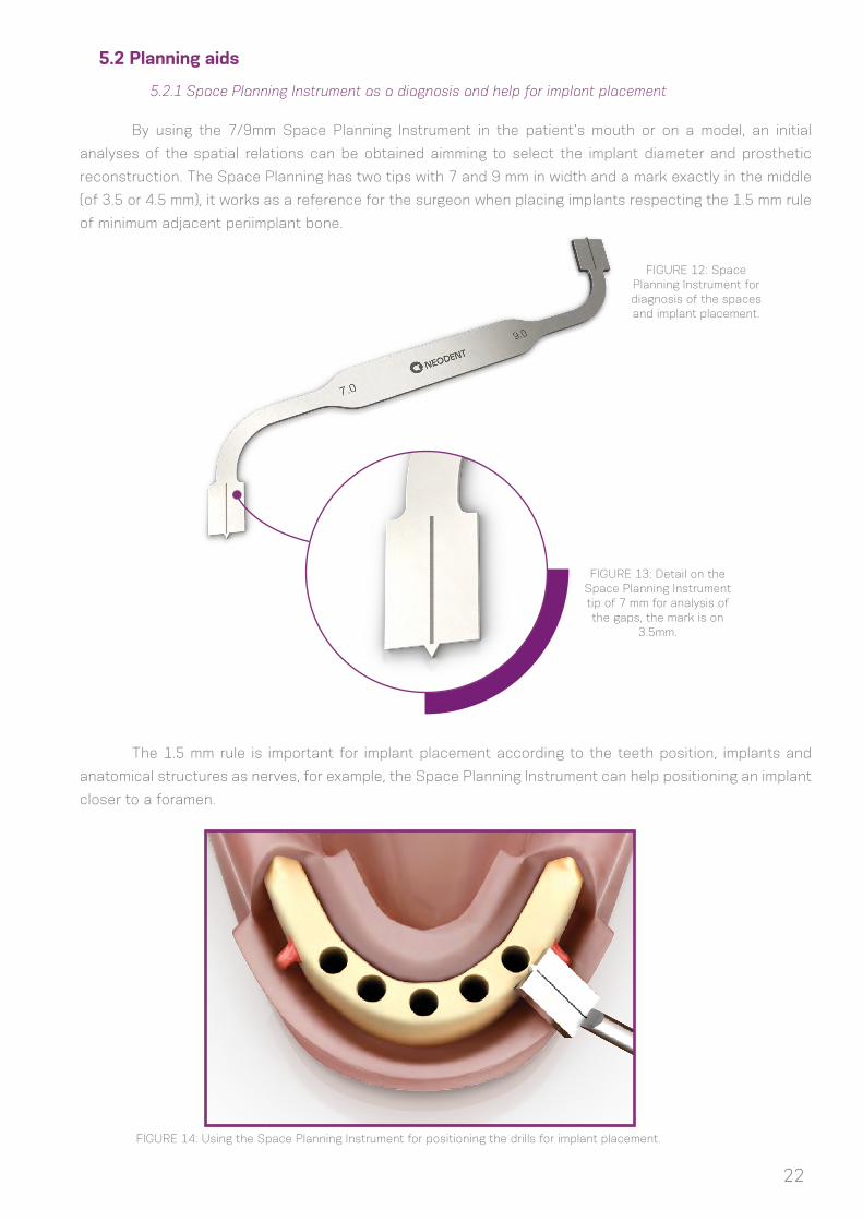
By using the 7/9mm Space Planning Instrument in the patient’s mouth or on a model, an initial
analyses of the spatial relations can be obtained aimming to select the implant diameter and prosthetic
reconstruction. The Space Planning has two tips with 7 and 9 mm in width and a mark exactly in the middle
(of 3.5 or 4.5 mm), it works as a reference for the surgeon when placing implants respecting the 1.5 mm rule
of minimum adjacent periimplant bone.
The 1.5 mm rule is important for implant placement according to the teeth position, implants and
anatomical structures as nerves, for example, the Space Planning Instrument can help positioning an implant
closer to a foramen.
FIGURE 12: Space Planning Instrument for diagnosis of the spaces and implant placement.
FIGURE 13: Detail on the Space Planning Instrument tip of 7 mm for analysis of the gaps, the mark is on
3.5mm.
FIGURE 14: Using the Space Planning Instrument for positioning the drills for implant placement.
23
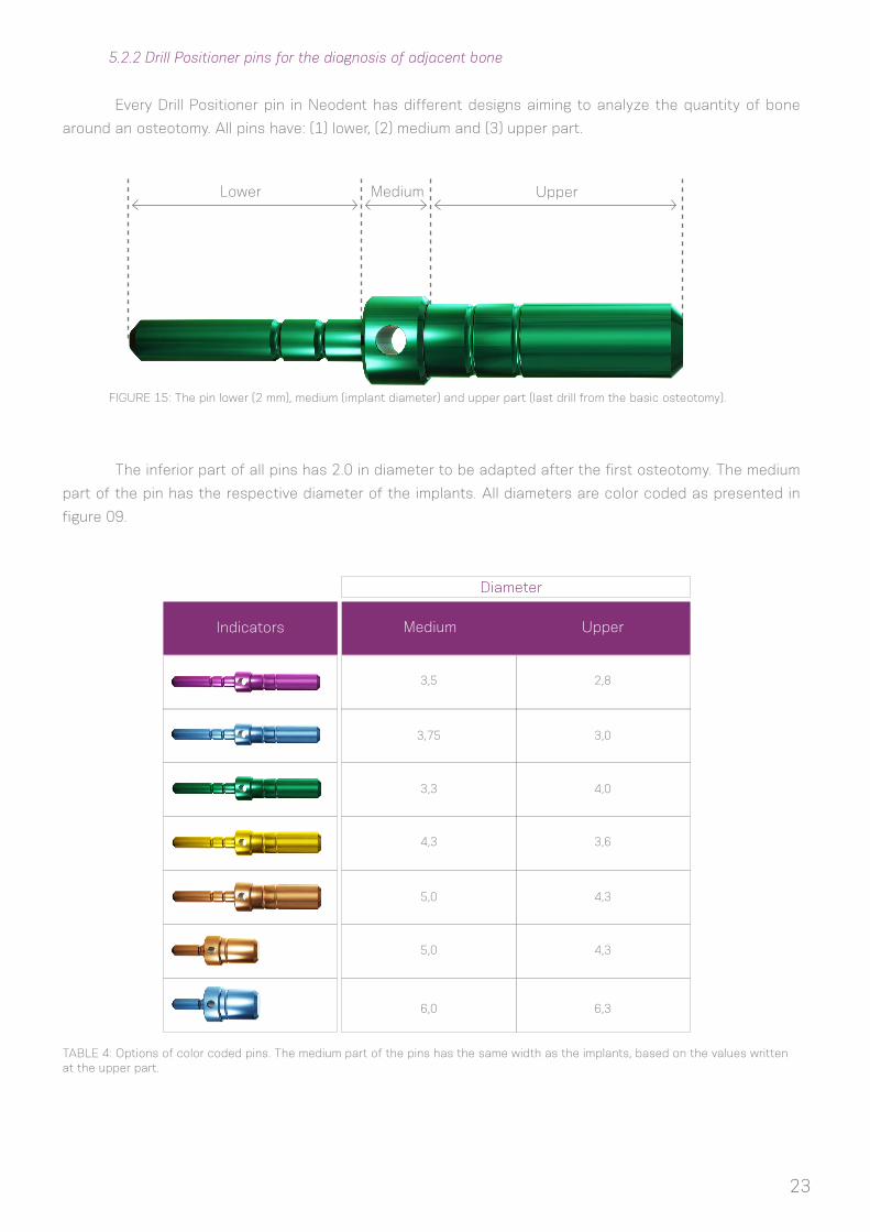
5.2.2 Drill Positioner pins for the diagnosis of adjacent bone
FIGURE 15: The pin lower (2 mm), medium (implant diameter) and upper part (last drill from the basic osteotomy).
TABLE 4: Options of color coded pins. The medium part of the pins has the same width as the implants, based on the values written at the upper part.
Every Drill Positioner pin in Neodent has different designs aiming to analyze the quantity of bone
around an osteotomy. All pins have: (1) lower, (2) medium and (3) upper part.
The inferior part of all pins has 2.0 in diameter to be adapted after the first osteotomy. The medium
part of the pin has the respective diameter of the implants. All diameters are color coded as presented in
figure 09.
Lower UpperMedium
Indicators Medium Upper
3,5
4,3
3,75
5,0
3,3
5,0
6,0
2,8
3,6
3,0
4,3
4,0
4,3
6,3
Diameter
24
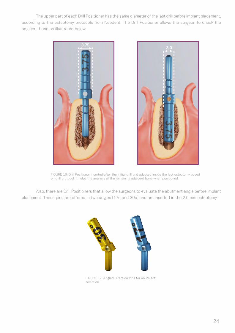
The upper part of each Drill Positioner has the same diameter of the last drill before implant placement,
according to the osteotomy protocols from Neodent. The Drill Positioner allows the surgeon to check the
adjacent bone as illustrated below.
Also, there are Drill Positioners that allow the surgeons to evaluate the abutment angle before implant
placement. These pins are offered in two angles (17o and 30o) and are inserted in the 2.0 mm osteotomy.
FIGURE 16: Drill Positioner inserted after the initial drill and adapted inside the last osteotomy based on drill protocol. It helps the analysis of the remaining adjacent bone when positioned.
FIGURE 17: Angled Direction Pins for abutment selection.
3,753,0
25
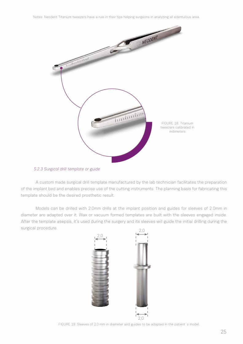
FIGURE 18: Titanium tweezers calibrated in
millimeters
5.2.3 Surgical drill template or guide
A custom made surgical drill template manufactured by the lab technician facilitates the preparation
of the implant bed and enables precise use of the cutting instruments. The planning basis for fabricating this
template should be the desired prosthetic result.
Models can be drilled with 2.0mm drills at the implant position and guides for sleeves of 2.0mm in
diameter are adapted over it. Wax or vacuum formed templates are built with the sleeves engaged inside.
After the template asepsis, it’s used during the surgery and its sleeves will guide the initial drilling during the
surgical procedure.
FIGURE 19: Sleeves of 2.0 mm in diameter and guides to be adapted in the patient`s model.
2,02,0
2,0
Notes: Neodent Titanium tweezers have a rule in their tips helping surgeons in analyzing all edentulous area.
26
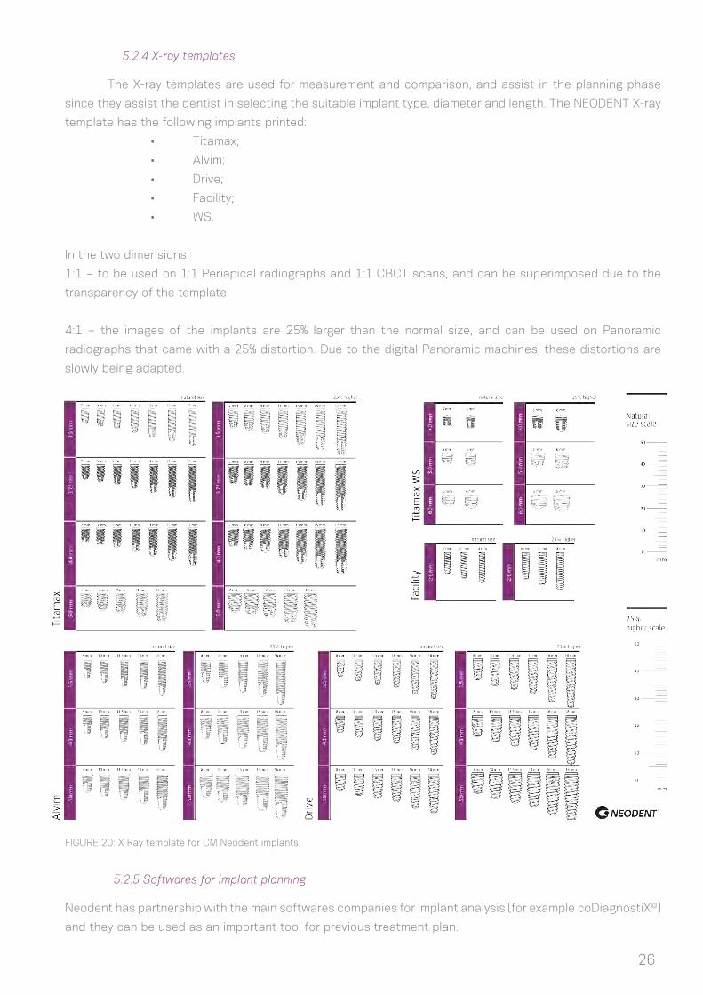
5.2.4 X-ray templates
The X-ray templates are used for measurement and comparison, and assist in the planning phase
since they assist the dentist in selecting the suitable implant type, diameter and length. The NEODENT X-ray
template has the following implants printed:
• Titamax;
• Alvim;
• Drive;
• Facility;
• WS.
In the two dimensions:
1:1 – to be used on 1:1 Periapical radiographs and 1:1 CBCT scans, and can be superimposed due to the
transparency of the template.
4:1 – the images of the implants are 25% larger than the normal size, and can be used on Panoramic
radiographs that came with a 25% distortion. Due to the digital Panoramic machines, these distortions are
slowly being adapted.
FIGURE 20: X Ray template for CM Neodent implants.
5.2.5 Softwares for implant planning
Neodent has partnership with the main softwares companies for implant analysis (for example coDiagnostiX©)
and they can be used as an important tool for previous treatment plan.

27
6.0 SURGICAL PROCEDURES
6.1 Implant bed preparation
Diameter, position and number of implants should be selected taking into account anatomy and
spacial circunstances. The measurements should be in accordance to the basic guidelines.
Basic implant bed preparation involves ridge preparation and twist drilling with water cooling, for
which the diameter and the design (if cylindrical or conical) of the selected implant determine the instruments
to be used.
Fine implant bed preparation involves profile drilling and tapping, for which the type of implant and
bone density determine the instruments to be used.
InstrumentationSteps
1. Basic implant bed preparation
Ridge preparation
Twist drilling
Initial drill
Twist drill 2.0mm; Direction indicator pin; Depth gauge
Drills shape to be defined according to the implant design and drill step by step and diameter according the implant width
Tapping
2. Fine implant bed preparation
Conical or cylindrical drills and profile drilling
Tap for Alvim or Facility in bone type I and II
Note: Titamax, Titamax EX, Alvim, Drive and WS implants can be placed using the same kit, where the Alvim and Drive implants
have conical drills for the implant bed preparation and Titamax and WS also have their specific drills. WS implants of 6.0mm in diameter
request extra drills present at one cassette for WS. The Facility implants have their own instrument kit as well.
6.1.1 Basic implant bed preparation
After opening a flap and exposing the bone, the preparation of the alveolar ridge begins. Once the
position of the implant has been decided previously and with surgical guide aids, the cervical cortical layer is
perforated with the initial drill (step1) and verified visually for its spatial positioning. The indicated rotations
per minutes (rpm) for drilling relies basically on the bone density, where in bone type I and II is applied 800-
1.200 rpm and type III and IV 500-800 rpm. Although short implants WS request a drilling protocol of 200-300
rpm, regardless of the bone density. This initial perforation works as a guide. After this, the 2.0mm twist drill
is used to reach the desired depth for the chosen implant, always remembering to consider the 1-2 mm sub
crestal insertion of the CM implant. Then a next drill is used to prepare the osteotomy following a sequence
according to the implant type and diameter, as chosen in the preoperative planning. All drills are adapted to
contra angles according to the ISO 1797-1 – Dental rotary instruments - Shank.
28
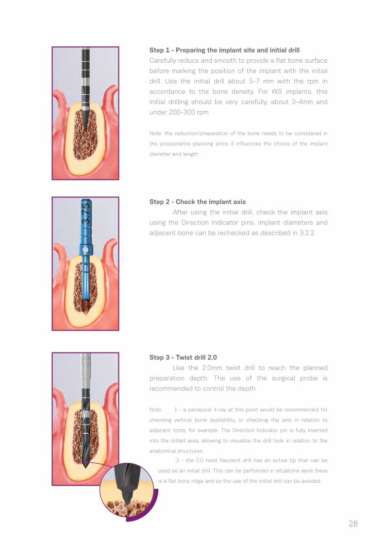
Step 1 - Preparing the implant site and initial drill
Carefully reduce and smooth to provide a flat bone surface
before marking the position of the implant with the initial
drill. Use the initial drill about 5-7 mm with the rpm in
accordance to the bone density. For WS implants, this
initial drilling should be very carefully, about 3-4mm and
under 200-300 rpm.
Note: the reduction/preparation of the bone needs to be considered in
the preoperative planning since it influences the choice of the implant
diameter and length.
Step 3 - Twist drill 2.0
Use the 2.0mm twist drill to reach the planned
preparation depth. The use of the surgical probe is
recommended to control the depth.
Note: 1 - a periapical X-ray at this point would be recommended for
checking vertical bone availability, or checking the axis in relation to
adjacent roots, for example. The Direction Indicator pin is fully inserted
into the drilled area, allowing to visualize the drill hole in relation to the
anatomical structures.
Step 2 - Check the implant axis
After using the initial drill, check the implant axis
using the Direction Indicator pins. Implant diameters and
adjacent bone can be rechecked as described in 3.2.2.
2 - the 2.0 twist Neodent drill has an active tip that can be
used as an initial drill. This can be performed in situations were there
is a flat bone ridge and so the use of the initial drill can be avoided.

29
Step 4 - Conical Drill 3.5
The tip of the tapered drill 3.5 adapts in the 2.0 mm
osteotomy and so the prepared bone guides this drilling.
This is the last basic drill step for the conical implants of
3.5 mm.
Note: an X-ray at this point would be
recommended for analysis of the bone
availability or to check the axis in relation
to adjacent roots. A radiographic pin of
the 3.5 implant is inserted into the drilled
area.
Step 5 - Conical Drill 4.3
The tip of the tapered drill 4.3 adapts in the 3.5 mm
osteotomy, guiding the drilling. This is the last basic drill
step for the conical implants of 4.3
Note: an X-ray at this point would be recommended for analysis of the
bone availability or to check the axis in relation to adjacent roots. A
radiographic pin of the 4.3 implant is inserted into the drilled area.
Step 6 - Conical Drill 5.0
The tip of the tapered drill 5.0 adapts in the 4.3 mm
osteotomy, guiding the drilling. This is the last basic drill
step for the conical implants of 5.0
Note: an X-ray at this point would be recommended for analysis of the
bone availability or to check the axis in relation to adjacent roots. A
radiographic pin of the 5.0 implant is inserted into the drilled area.
6.1.1.1 For conical Alvim and Drive implants
6.1.1.2 For cylindrical Titamax implants
30
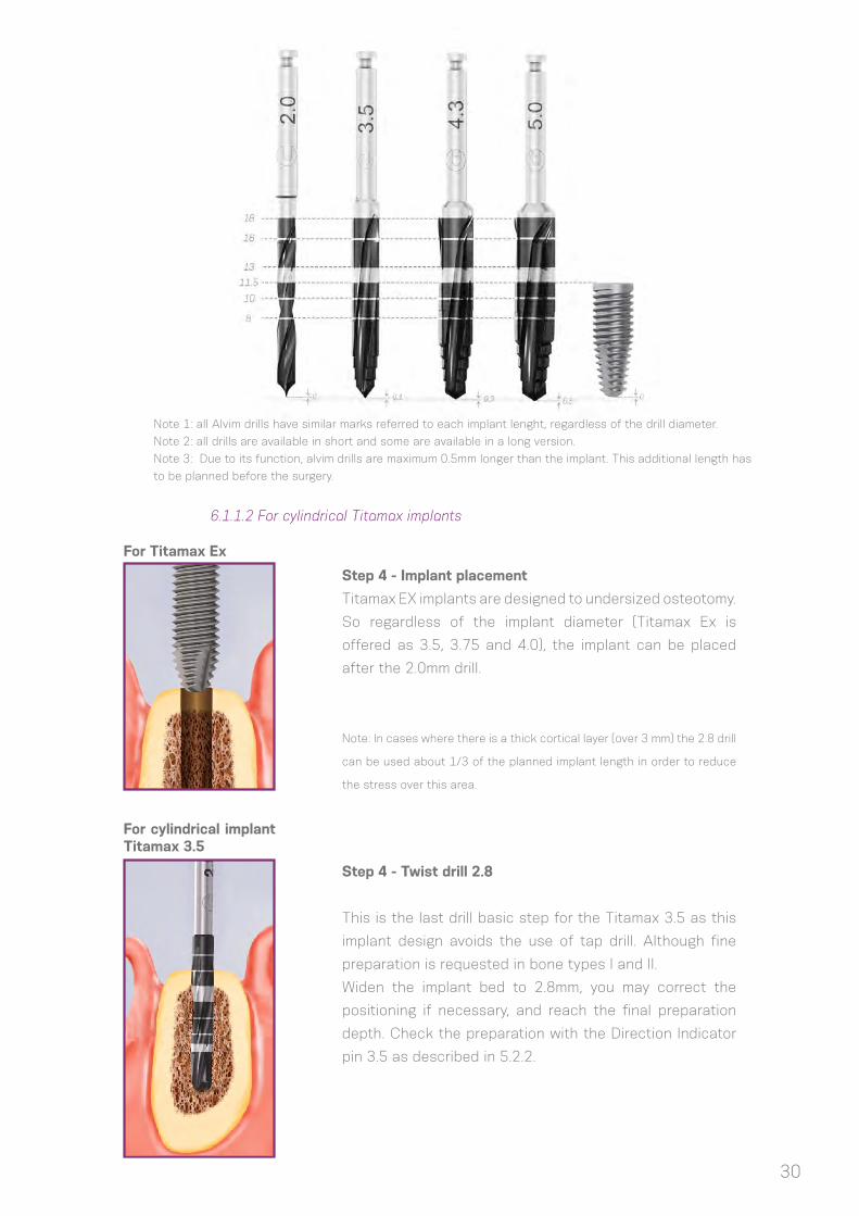
Step 4 - Implant placement
Titamax EX implants are designed to undersized osteotomy.
So regardless of the implant diameter (Titamax Ex is
offered as 3.5, 3.75 and 4.0), the implant can be placed
after the 2.0mm drill.
Note: In cases where there is a thick cortical layer (over 3 mm) the 2.8 drill
can be used about 1/3 of the planned implant length in order to reduce
the stress over this area.
Step 4 - Twist drill 2.8
This is the last drill basic step for the Titamax 3.5 as this
implant design avoids the use of tap drill. Although fine
preparation is requested in bone types I and II.
Widen the implant bed to 2.8mm, you may correct the
positioning if necessary, and reach the final preparation
depth. Check the preparation with the Direction Indicator
pin 3.5 as described in 5.2.2.
For Titamax Ex
For cylindrical implant Titamax 3.5
Note 1: all Alvim drills have similar marks referred to each implant lenght, regardless of the drill diameter.
Note 2: all drills are available in short and some are available in a long version.
Note 3: Due to its function, alvim drills are maximum 0.5mm longer than the implant. This additional length has
to be planned before the surgery.

31
Step 5 - Pilot drill 2/3
Use the 2/3 pilot drill to widen the initial portion of the
implant bed in situations where the drill 3.0 is requested as
a next step. Insert the drill until the mark is reached.
Step 6 - Twist drill 3.0
After the preparation with the pilot 2/3 drill, widen the
whole implant bed to 3.0mm and check with the 3.75
Direction Indicator pin as described in 3.2.2. 3.0 drill can
be used as a last basic step drill or an intermediate drill of
a sequence, depending on the implant diameter chosen to
be placed.
Note: This is the last basic drill step for the Titamax implants of 3.75 mm
as this implant design avoid the use of tap drill. Although fine preparation
is requested in bone types I and II.
Step 7 - Twist drill 3.3
This is the last drill basic step for the Titamax and WS
implants of 4.0mm as these implant designs avoid the
use of tap drill. Although fine preparation is requested in
bone types I and II. Widen the implant bed to 3.3 mm, you
may correct the positioning if necessary, and reach the
final preparation depth. Check the preparation with the
Direction Indicator pin 4.0 as described in 5.2.2.
For cylindrical implants Titamax and WS
For cylindrical implants Titamax and WS
For cylindrical implants Titamax and WS 4.0
32
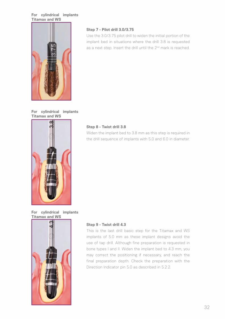
Step 7 - Pilot drill 3.0/3.75
Use the 3.0/3.75 pilot drill to widen the initial portion of the
implant bed in situations where the drill 3.8 is requested
as a next step. Insert the drill until the 2nd mark is reached.
Step 8 - Twist drill 3.8
Widen the implant bed to 3.8 mm as this step is required in
the drill sequence of implants with 5.0 and 6.0 in diameter.
Step 9 - Twist drill 4.3
This is the last drill basic step for the Titamax and WS
implants of 5.0 mm as these implant designs avoid the
use of tap drill. Although fine preparation is requested in
bone types I and II. Widen the implant bed to 4.3 mm, you
may correct the positioning if necessary, and reach the
final preparation depth. Check the preparation with the
Direction Indicator pin 5.0 as described in 5.2.2.
For cylindrical implants Titamax and WS
For cylindrical implants Titamax and WS
For cylindrical implants Titamax and WS

33
Step 10 - Pilot drill 4.3/5.3
Use the 4.3/5.3 pilot drill to widen the initial portion of the
implant bed in situations where the drill 5.3 is requested as
a next step: for implants of 6.0 in diameter. Insert the drill
until the 2nd mark is reached.
Step 11 - Twist drill 5.3
This is the last drill basic step for the WS implants of 6.0 mm
as this implant design avoids the use of tap drill. Although
fine preparation is requested in bone types I and II. Widen
the implant bed to 5.3 mm and reach the final preparation
depth. Check the preparation with the Direction Indicator
pin 6.0 as described in 5.2.2.
For cylindrical implants WS
For cylindrical implants WS
Note: all Twist drills have similar marks referred to each Titamax implant length, regardless of the drill diameter

34
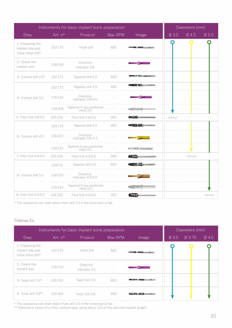
6.1.1.3 For narrow Facility implants
Each Facility implant has one specific drill according to their lengths. Depending on the chosen
implant, each drill has a mark at the bone level or a reference at 2 mm over its length.
The following sequences summarize the use of instruments for the basic bed preparation according
to the implant diameter and type.
Note: all Twist drills have similar marks referred to each Facility implant length.
Note: There are X ray positioners for
checking the Facility implant axis
35
Titamax Ex
* The sequence can start direct from drill 2.0 if the bone bed is flat.
* The sequence can start direct from drill 2.0 if the bone bed is flat.** Optional in cases of a thick cortical layer using about 1/3 of the planned implant length.
Instruments for basic implant bone preparation Diameters (mm)
Step
1 -Preparing the
implant site and
initial initial drill*
3- Twist drill 2.0*
2- Check the
implant axis
4- Twist drill 2.8**
103.170
103.162
128.019
103.163
Direction
indicator 3.5
Twist Drill 2.8
Twist Drill 2.0
Initial Drill 800
800
800
-
Art. n° Product Max RPM Image Ø 3.5 Ø 3.75 Ø 4.0
Instruments for basic implant bone preparation Diameters (mm)
Step
1 -Preparing the
implant site and
initial initial drill*
2- Check the
implant axis
3- Conical drill 2.0*
4- Conical drill 3.5
103.170
103.171
103.172
103.173
103174
129.009
129.013
129.014
128.019
128.022
128.023
128.019
Initial drill
Tapered drill 2.0
Tapered drill 3.5
Tapered drill 4.3
Tapered drill 5.0
Tapered X-ray positionerHelix 3.5
Tapered X-ray positionerHelix 4.3
Tapered X-ray positionerHelix 5.0
Direction Indicator 2.8/3.5
Direction Indicator 3.6/4.3
Direction Indicator 4.3/5.0
Direction
Indicator 2.8
800
800
800
800
800
-
-
-
-
-
-
-
6- Conical drill 4.3
8- Conical drill 5.0
Art. n° Product Max RPM Image Ø 3.5 Ø 4.3 Ø 5.0
- -
-
103.220
103.219
103.216
300
300
300
9- Pilot Drill 4.3/5.0
7- Pilot Drill 3.6/4.3
5- Pilot Drill 2.8/3.5
Pilot Drill 4.3/5.0
Pilot Drill 4.3/5.0
Pilot Drill 2.8/3.5 Optional
Optional
Optional

36
Titamax and WS
* The sequence can start direct from drill 2.0 if the bone bed is flat.
** This is the only Direction Indicator pin for WS implant.
Note: All narrow parts of the drill positioner pin can be used for checking the implant axis as indicated in page 23.
Diameters (mm)
Image
Ø 4.0Ø 3.5 Ø 5.0Ø 3.75 Ø 6.0
-
-
Instruments for basic implant bone preparation
Step
1 -Preparing the
implant site and
initial initial drill*
2- Check the
implant axis
3- Twist drill 2.0*
4- Twist drill 2.8
103.170
103.162
103.163
103.164
128.021
128.022
103.220
103.215
128.025
128.024
103.169
103.221
128.019
103.217
128.020
103.218
103.213
103.166
103.168
103.167
128.019
Initial drill
Direction Indicator 2.8/3.5
Pilot drill4.3/5.0
Pilot drill4.3/5.3
Direction Indicator 5.3/6.0
Direction Indicator 4.3/5.0
Twist Drill 5.3
Pilot drill5.3/6.0
Pilot drill 2/3
Pilot drill3.3/4.0
Direction Indicator 3.3/4.0
Pilot Drill 3.0/3.75
Direction Indicator 3.0/3.75
Direction Indicator 3.6/4.3
Direction
Indicator 2.8
1200
1200
300
1200
1200
1200
1200
300
1200
1200
300
300
-
1200
300
6- Twist Drill 3.0
7- Twist Drill 3.3
Twist Drill 3.3
Twist Drill 3.0
10- Twist Drill 4.3
Twist Drill 4.3
Twist Drill 2.8
Twist Drill 3.8
Twist Drill 2.0
8- Pilot drill 3.3/4.0
9- Twist Drill 3.8
11- Pilot drill 4.3/5.0
12- Pilot drill 4.3/5.3
13- Twist Drill 5.3
14- Pilot drill 5.3/6.0
5- Pilot Drill 2/3
Art. n° Product Max RPM Image
-
-
-
-
-
-
-
-
-
-
-
-
-
- -
- -
-
-
- -
-
**

Facility
* The sequence can start direct from drill 2.0 if the bone bed is flat.
Instruments for basic implant bone preparation Diameters (mm)
Step
1 -Preparing the
implant site and
initial initial drill*
3- Check the
implant length
2- Facility twist
drill 2.0*
4- Facility drill 10
4- Facility drill 12
4- Facility drill 14
103.330
129.016
103.331
103.341
103.342
103.343
Facility Twist
drill 2.0
Facility Drill 14
Facility Drill 12
Facility Drill 10
Facility X Ray
positioner
Facility Initial
Drill800
800
800
800
800
Art. n° Product Max RPM Image
-
-
-
-
Ø 10 Ø 12 Ø 14
37
FIGURE 21: Pilot drill for the fine implant bed preparation. It helps the implant coronal positioning in areas of bone with higher density: if bone level, 1, 2 or 3mm subcrestal. It is not necessity for Drive CM implants.
bone level
1mm subcrestal
2mm subcrestal
3mm subcrestal
FIGURE 22: Tap drills were engineered to be used in bone bed types I and II for Alvim and Facility implants.
6.1.2. Fine implant bed preparation
6.1.2.1. Pilot Drill
6.1.2.2. Tap Drill
The fine bed preparation encompasses (1) pilot drilling and (2) tapping, when needed. Instrumentation
depends on the implant type, the implant diameter and the type of bone. Osteotomy in bone type I and II
requires final pilot drills in because of the final implant positioning. Tap drills are only requested for the use
of Alvim and Facility implants in areas of high bone density.
Pilot drills are used to prepare the implant bed
when widening from one twist drill to another in the basic
drilling procedure. For fine bone preparation, pilot drills help
in positioning the platform of the CM implant according to
the bone bed, if at the bone level, 1, 2 or 3mm subcrestal in
areas of a higher cortical layer is present. So usually they
are only used in bone type I and II and indicated as optional
in bone types III-IV. Drive CM implants don’t request the use
of this drill because of its coronal design. The rpm used for
the pilot drills is maximum 300.
Tapping prepares the bed for a specific thread type. It is a step used
for bone type I and II in order to keep the insertion torque in a desirable range.
The tap drill is available for Alvim and Facility.
Tapping is performed by coupling the tap to the contra angle or
wrench. While for Facility it is indicated to be started by the contra angle and
finalized with the wrench, for Alvim there are two options of use: with the
contra angle handpiece and the WS implant driver (hexagon connection) or
with the torque wrench (WS implant driver for torque wrench – with a hexagon
connection). The rpm should be of 15-30 rpm when using a contra angle and a
slow clockwise rotating movement for the use with wrench, for removing in the
counterclockwise direction. The maximum torque of use should be 60 N.cm for
the Alvim and 45 N.cm for Facility.

38
FIGURE 23. Option for taping with Alvim.
FIGURE 24. Options for taping with Facility. First start with the contra angle and finish with the wrench.
105.002105.001
+
+
+
+
+
105.111
104.050
104.050
111.037111.037
111.035
111.035
Contra-Angle
+
Contra-Angle
+

39
*Optional.** Only in bone type I and II.
Note: Neodent surgical drills can be used about 25 times in bone type III/IV and 20 times in type I/II since conditions of use and indications, as irrigation and rotation, are respected. Regardless of this suggestion of times for use, all drills have to be checked about their sharpening conditions. The cleaning of all drill has to be made one to one, avoiding mechanical contact of the blades during this procedure.
The following table summarizes the use of Pilot and Tap drills for the fine bone preparation.
Facility tap drill can be used in contra angle and wrench.
Instruments for basic implant bone preparation Implants
Art. n° Titamax Alvim Drive Facility WSTitamax ExProduct Max RPM Image
Pilot drill
2.8/3.5
Pilot drill
3.6/4.3
Alvim tap
drill 3.5
Pilot drill
3.0/3.75
Pilot drill
4.3/5.0
Alvim tap
drill 4.3
Pilot drill
3.3/4.0
Pilot drill
5.3/6.0
Alvim tap
drill 5.0
Facility
tap drill
103.216
103.219
111.036
103.217
103.220
111.037
103.218
103.221
111.038
111.035
300 Ø3.5 Ø3.5*
Ø4.0
Ø5.0
- -
- - - -
- -
-- -
- - - --
- -
-- -
- - - --
- -
-- -
- - - -
- -
-- -
- - -
-
Ø5.0* Ø5.0
Ø4.3**
Ø2.9*
Ø3.75
Ø4.3 Ø4.3*
Ø3.5**
Ø5.0**
Ø6.0
300
30
300
300
30
300
300
30
30
Step 1- Pilot Drill
Perform the osteotomy with the conical drills and
depending on the planned level for final implant
positioning (bone level, 1 or 2 mm sub crestal), use the
pilot drill for the implant placement.
Step 2- Tapping the threads in dense bone
Tap the full length of the planned implant with the
Alvim tap drill.
6.1.2.3. Example of fine implant bed preparation
Here follows an example of fine bed preparation for an Alvim implant of ø 4.3 mm and length of 13 mm
placed in bone type I or II, turning the use of taping and pilot drills necessaries. The steps described followed the
basic implant bed preparation (6.1.1.1).
40
6.1.3 Options for drilling
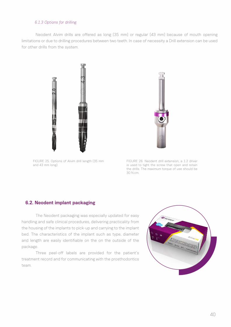
Neodent Alvim drills are offered as long (35 mm) or regular (43 mm) because of mouth opening
limitations or due to drilling procedures between two teeth. In case of necessity a Drill extension can be used
for other drills from the system.
FIGURE 25. Options of Alvim drill length (35 mm and 43 mm long).
FIGURE 26. Neodent drill extension, a 1.2 driver is used to tight the screw that open and retain the drills. The maximum torque of use should be 30 N.cm.
6.2. Neodent implant packaging
The Neodent packaging was especially updated for easy
handling and safe clinical procedures, delivering practicality from
the housing of the implants to pick-up and carrying to the implant
bed. The characteristics of the implant such as type, diameter
and length are easily identifiable on the on the outside of the
package.
Three peel-off labels are provided for the patient’s
treatment record and for communicating with the prosthodontics
team.

41
Instructions on opening the implant package
Step 1
Step 2
Step 3
Step 5
Step 4
Step 6
Open blister and remove the vial, pouring
it onto a sterile area
After breaking the sterility seal in the
blister, hold the package and twist the
cap to open.
Note: for Acqua implants keep the vial upright to prevent the liquid from flowing out
Remove the implant from the tube lifting
the cap, it has the implant attached.
Note: for Acqua implants keep the vial upright to prevent the liquid from flowing out
Capture the implant using the contra
angle hand piece. Grip the stand and
rotate it in order to find the perfect
seating between the drive at the contra
angle and the implant. Make sure that
the implant driver is fully seated into the
implant
While gripping the stand, remove the cap
Transport the implant to the implant bed

42
Instructions on opening the conventional implant package
Step 1
Step 2
Step 3
Step 5
Step 4
Open blister and remove the vial, pouring
it onto a sterile area
After breaking the sterility seal in the
blister, hold the pacakeg and pull the cap
to open
The implant is holded at the tube
Make sure that the implant driver is fully
seated into the implant and take it into
position
Capture the implant using the contra
angle hand piece. Grip the stand and
rotate it in order to find the perfect
seating between the drive at the contra
angle and the implant.

43
6.3. Placing the implant
CM Neodent implant were planned to start placing with the contra angle or by hands and finalize it
with the wrench. The maximum speed recommended in the surgical motors is of 30 rpm and the torque of
45N.cm.
The following instructions present the step by step of how CM Neodent implant is handled with the
contra angle for placement.
6.3.1. Place the implants with the contra angle
Step 1- Adapt the hand piece implant driver
Hold the implant through its blister and attach
the hand piece driver of the CM implant. All
hand pieces drivers present a ring in the active
tip in order to keep the implant stable during
carrying. Implant drivers for torque wrench
don’t have the rubber for keeping implants in
positioning for transport.
Step 2- Place the implant with the contra angle
into the implant bed.
Place the implant into its final positioning with a
maximum torque of 45 N.cm and 30 rpm turning
it clockwise.
Caution: Corrections of the vertical positioning
through reverse rotations during the surgery may
lead to decrease of initial/mechanical stability.

44
Step 3 - Implant final positioning
CM Neodent implants have an internal hexagon index called
Exact. Make sure that the final implant positioning has one
of the dots bucally positioned for prosthetic orientation.
The implant drivers have six dots that coincide with the
six sides of Exact. Position one of the dots on the driver
buccally to ensure optimal placement of CM abutments
indexed with Exact.
AA
Note 1: There are three similar marks at 1mm intervals on the contra angle
and the wrench implant carries. They will guide the depth of the implant
final placement as following: 1st strip to 1 mm subcrestal, 2nd to 2 and the
3rd to 3 mm. Every full turn over the implants will result in: (1) 0.6mm in WS
implants; (2) 2.2 mm Drive implants; (3) 1.4 mm in Alvim; and (3) 1.2 mm for
all the other offered implants.
Note 2: One important difference from the contra angle driver to the wrench
one is that the contra angle driver has a rubber in the tip that keeps the
implant in position. So wrench drivers are not indicated to transport the
implant from the blister to the mouth.
All sequence described below can be repeated
by hands using the Manual implant driver – Contra Angle
(C.A.) instead of the contra angle.
6.3.2. Place the implants by hands
FIGURE 27. Any instrument for contra angle can be adapted in the Manual implant driver –C.A.
CM Implant DriverContra-Angle
CM Implant DriverTorque Wrench - Long
Manual Implant DriverContra-Angle
bone level1mm subcrestal
2mm subcrestal
3mm subcrestal
CM Implant DriverContra-Angle

45
Remove the contra angle driver from the implant and adapt
the driver for the wrench for final implant positioning and
torque measurement. There are 2 options of wrench driver:
long and short. First adapt the driver inside the implants
with the fingers, and then engage the wrench over the
driver. No wrench drivers should be used to transport the
implant from a place to another, because the fixture may
fall. Apply torque until the implant reaches its final position.
All wrenches show the torques of 10/15/20/32/45 and
60N.cm, and torques over 60 N.cm are contra indicated.
Caution: Corrections of the vertical positioning through reverse rotations during the surgery may lead to decrease of initial/mechanical stability.
For submucosal healing (under a closed mucoperiostal flap)
the use of a cover screw is indicated. A second surgical
procedure is required for uncovering the implant and
insertion of the desired secondary component.
The NEODENT system has two cover screws, which are sold
separately and are packed sterile, at implant level and 2.0
mm (above implant shoulder) because of the subcrestal
positioning.
Cover Screw
2mm Cover Screw
6.3.3. Finalize the implant positioning with the wrench
6.4. Soft tissue management
After implantation, the implant is closed with a cover screw or a healing cap (or healing abutment)
to protect the implant. The surgeon can choose between submucosal or transmucosal healing and has
all options available for soft tissue management made possible through a set of secondary healing
components.
6.4.1 Two stage/ submucosal healing
CM Implant DriverTorque Wrench - Long
CM Implant DriverTorque Wrench - Short

46
Step 1- Inserting the cover screw
Ensure that the internal configuration is clean and bloodless.
Pick up the cover screw with the 1,2mm screwdriver, the
perfect fit secures the transport to the implant, and hands
tighten the screw.
Step 2- Close of the flap
Adapt the flaps and suture with tension free sutures.
47
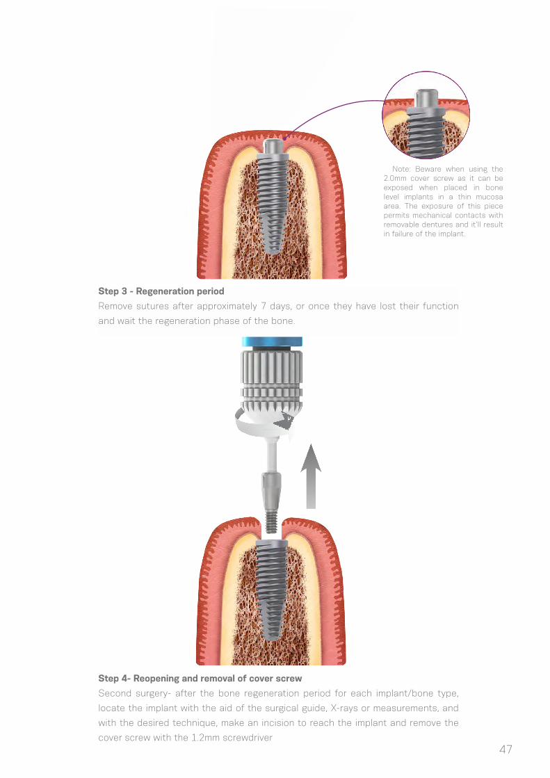
Step 4- Reopening and removal of cover screw
Second surgery- after the bone regeneration period for each implant/bone type,
locate the implant with the aid of the surgical guide, X-rays or measurements, and
with the desired technique, make an incision to reach the implant and remove the
cover screw with the 1.2mm screwdriver
Step 3 - Regeneration period
Remove sutures after approximately 7 days, or once they have lost their function
and wait the regeneration phase of the bone.
Note: Beware when using the 2.0mm cover screw as it can be exposed when placed in bone level implants in a thin mucosa area. The exposure of this piece permits mechanical contacts with removable dentures and it’ll result in failure of the implant.

48
Step 5- Insertion healing abutment
Rinse the exposed internal connection of the implant with
sterile saline solution, insert a healing abutment (or an
abutment if it can be chosen). Adapt the soft tissue and
suture around the component. More info about healing
abutments options can be found at #4.5.
Step 6 - Wound closure
Adapt the soft tissue and suture around the component.
49
A variety of healing caps and abutments are available in the Neodent CM system, shaping the soft-
tissue during transmucosal healing right after implant placement. The components can be for intermediate
use, where they are replaced with the definite abutment in the final restoration phase, or with the definite
abutment with a temporary restoration. This phase can be defined as one stage surgery (if the healing
abutment is chosen after the surgery) or immediate loading (if the proper abutment is chosen).
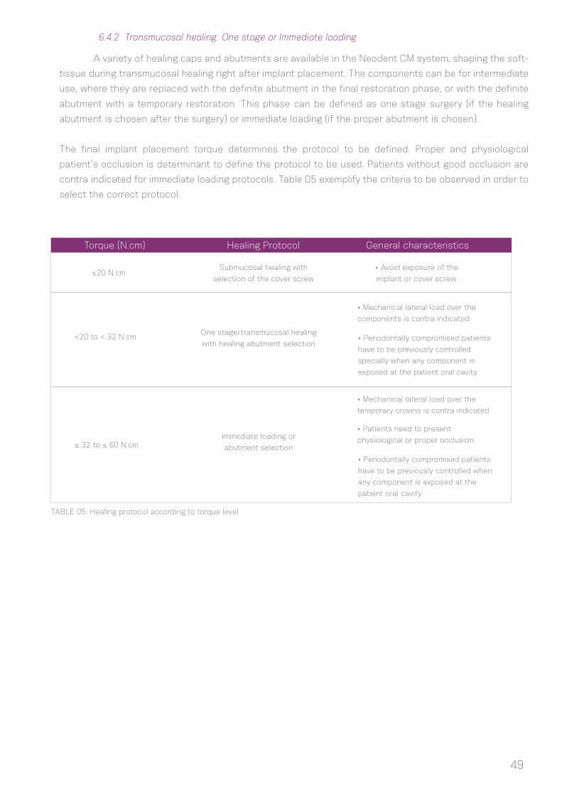
The final implant placement torque determines the protocol to be defined. Proper and physiological
patient’s occlusion is determinant to define the protocol to be used. Patients without good occlusion are
contra indicated for immediate loading protocols. Table 05 exemplify the criteria to be observed in order to
select the correct protocol.
6.4.2 Transmucosal healing: One stage or Immediate loading
TABLE 05: Healing protocol according to torque level
Torque (N.cm) Healing Protocol General characteristics
≤20 N.cm
<20 to < 32 N.cm
≤ 32 to ≤ 60 N.cm
Submucosal healing with
selection of the cover screw
One stage/transmucosal healing
with healing abutment selection
Immediate loading or
abutment selection
• Avoid exposure of the
implant or cover screw.
• Mechanical lateral load over the
components is contra indicated.
• Mechanical lateral load over the
temporary crowns is contra indicated.
• Periodontally compromised patients
have to be previously controlled
specially when any component is
exposed at the patient oral cavity.
• Periodontally compromised patients
have to be previously controlled when
any component is exposed at the
patient oral cavity.
• Patients need to present
physiological or proper occlusion.
50
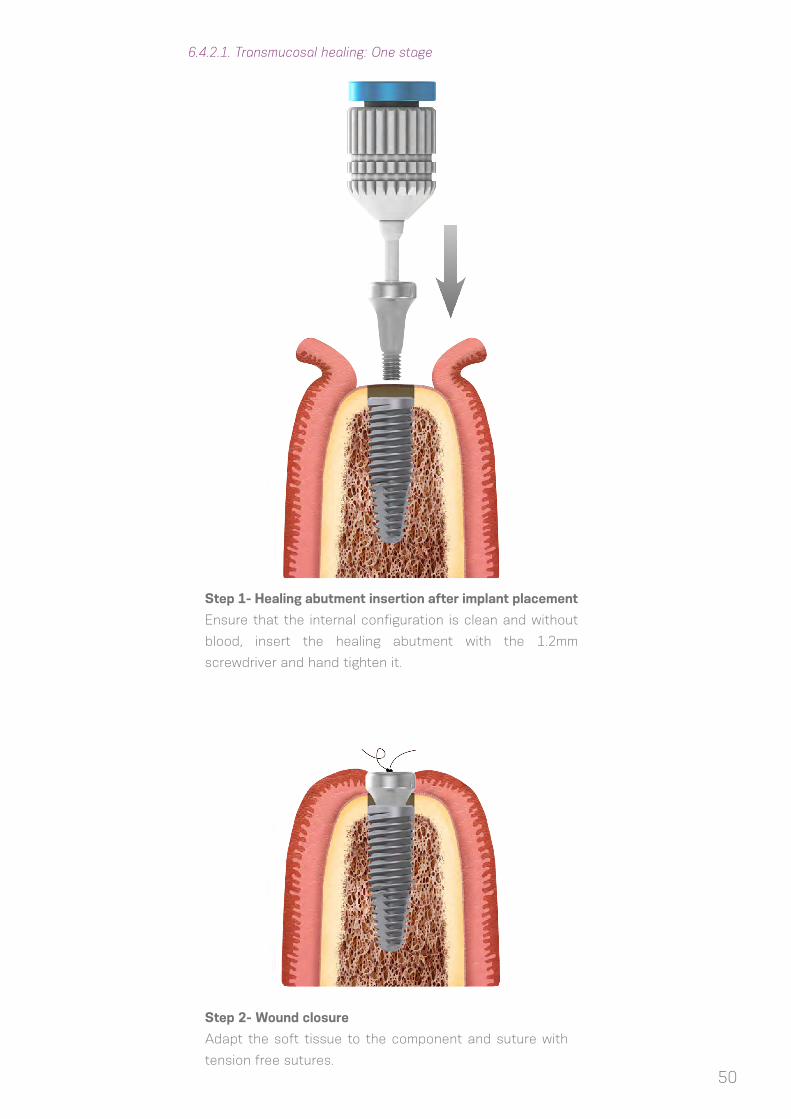
6.4.2.1. Transmucosal healing: One stage
Step 1- Healing abutment insertion after implant placement
Ensure that the internal configuration is clean and without
blood, insert the healing abutment with the 1.2mm
screwdriver and hand tighten it.
Step 2- Wound closure
Adapt the soft tissue to the component and suture with
tension free sutures.

51
6.5 Overview of the healing abutments
The Neodent system has a variety of healing abutments, with different diameters and trasmucosal
heights to suit to the definitive abutment. Therefore the correct choice is of utmost importance to have the
right healing of the soft tissues, with controlled pressure and respect of the biological width.
Basically there are different shapes of CM healing abutments to be adapted to the surgeon
necessities:
Transm
uco
sal H
eig
ht
Ø3.3 Ø4.5
0.8mm 0.8mm
Transmucosal
heigth from 0.8 - 5.5mm
Healing Abutments
Height Measurer
for Facility
4,5mm
2,5mm3,5mm
3,5mm3,5mm
5,5mm5,5mm
1,5mm
1,5mm1,5mm
0,8mm
Height Measurer
for CM
Ø of 3.3 or 4.5
1.5mm 1.5mm
2.5mm 2.5mm
3.5mm 3.5mm
4.5mm 4.5mm
5.5mm
6.5mm
5.5mm
6.5mm
Aiming to select the proper abutment and to check
the measurement of the remaining mucosa for component
selection, there are 3 options of Height Measurer (for CM,
WS and Facility) which are used adapted in the implants
serving as a reference to select the right component.
The height of the components varies from 0.8mm to 6.5mm and should be chosen according to
the gingival height. Since the internal design of the healing abutment is identical to that of the definite
component, if the height of the healing cap was chosen too high, the soft tissue will heal accordingly. If the
height of the definite component is not compatible, let´s say lower, then it will exert a lot of pressure on
the soft tissues and the patient will complain of pain due to compression. Therefore the choice of healing
caps with the same width and transmucosal height are recommended. If the definite component needs to
be changed, then the patient needs to be anesthetized and an adequate timing given for the soft tissue to
readapt.

52
6.5.1 Overview of the CM Abutments and corresponding Healing Caps
All Neodent healing abutments were strategically designed to create the correct emergence profile
adapted to the margin of all abutments in a way it stays 0.9mm under the mucosa.
0,9mm
2,5mmA
butm
ent
Corr
esp
ond
ing
Healin
g A
butm
ent
Transmucosal
Heights
Transmucosal
Heights
Type Pro Peek Abutment
4.5mm 6.0mm
4.5mm 4.5mm
0.8mm
0.8mm 0.8mm
0.8mm
1.5mm
1.5mm 1.5mm
1.5mm
2.5mm
2.5mm 2.5mm
4.5mm
4.5mm 4.5mm
2.5mm
4.5mm
3.5mm
3.5mm 3.5mm
5.5mm
5.5mm 5.5mm
3.5mm
5.5mm
Available Ø
Temporary abutment options
Available Ø

Ab
utm
ent
Corr
esp
ond
ing
Healin
g A
butm
ent
Type Miniconical Microconical CM Abutment EquatorMiniconical(angled and exact)
4.8mm
4.5mm
4.8mm
4.5mm
3.3mm
3.3mm
4.8mm
4.5mm
4.8mm
4.5mm
0.8mm
0.8mm
0.8mm
0.8mm
0.8mm
0.8mm
0.8mm
0.8mm
0.8mm
0.8mm
1.5mm
1.5mm
1.5mm
1.5mm
1.5mm
1.5mm
1.5mm
1.5mm
1.5mm
1.5mm
2.5mm
2.5mm
2.5mm
2.5mm
2.5mm
2.5mm
2.5mm
2.5mm
2.5mm
2.5mm
3.5mm
3.5mm
3.5mm
3.5mm
3.5mm
3.5mm
3.5mm
3.5mm
3.5mm
3.5mm
4.5mm
4.5mm
4.5mm
4.5mm
4.5mm
4.5mm
4.5mm
4.5mm
4.5mm
4.5mm
5.5mm
5.5mm
5.5mm
5.5mm
5.5mm
5.5mm
5.5mm
5.5mm
Available Ø
Screw retained CM options
Available Ø
Transmucosal
Heights
Transmucosal
Heights
Ab
utm
ent
Corr
esp
ond
ing
Healin
g A
butm
ent
TypeCM Anatomic
abutment (and Exact)
CM Anatomic abutment
(and Exact)
Universal Post (straight, angled
and Exact)
Universal Post (straight, angled
and Exact)
3.3mm6.0 mm(buccal)/
5.0 mm (lateral)
4.7 mm(buccal)/
4.3 mm (lateral)4.5mm
4.5mm 4.5mm 3.3mm 4.5mm
0.8mm 0.8mm
0.8mm 0.8mm
1.5mm 1.5mm1.5mm 1.5mm
1.5mm 1.5mm1.5mm 1.5mm
2.5mm 2.5mm2.5mm 2.5mm
2.5mm 2.5mm2.5mm 2.5mm
3.5mm 3.5mm3.5mm 3.5mm
3.5mm 3.5mm3.5mm 3.5mm
4.5mm 4.5mm
4.5mm 4.5mm
5.5mm 5.5mm
5.5mm 5.5mm
Available Ø
Cement retained CM options
Available Ø
Transmucosal
Heights
Transmucosal
Heights
53

54
Ab
utm
ent
Corr
esp
ond
ing
Healin
g A
butm
ent
Type Microconical
Facility Anatomic abutment
Equator
1.5mm
1.5mm
1.5mm
1.5mm
1.5mm
1.5mm
2.5mm
2.5mm
2.5mm
2.5mm
2.5mm
2.5mm
3.5mm
3.5mm
3.5mm
3.5mm
3.5mm
3.5mm
4.5mm
4.5mm
Options for Facility
Transmucosal
Heights
Transmucosal
Heights
Note 1: for Facility, the 1.5mm healing cap is also used as cover screw
Ab
utm
ent
Ab
utm
ent
Corr
esp
ond
ing
Healin
g A
butm
ent
Corr
esp
ond
ing
Healin
g A
butm
ent
Transmucosal
Heights
Transmucosal
Heights
Transmucosal
Heights
Transmucosal
Heights
Note 2: for WS, there is a specific cover screw and healing cap
Type TypeWS MiniConical
WS Universal
Post
WS Abutment
4.8mm 4.5mm4.8mm
4.5mm 4.5mm4.5mm
0.8mm 0.8mm0.8mm
0.8mm 0.8mm0.8mm
1.5mm 1.5mm1.5mm
1.5mm 1.5mm1.5mm
2.5mm 2.5mm2.5mm
2.5mm 2.5mm2.5mm
3.5mm 3.5mm3.5mm
3.5mm 3.5mm3.5mm
Available Ø Available Ø
Screw retained WS options Cement retained WS options
Available Ø Available Ø

7. HEALING PHASE
8. ABUTMENT TRY IN KIT
The Healing protocol relies on:
(1) Final placement torque of the implants or primarily stability measured with the torque wrench;
(2) Type of bone when a minimum of 20 N.cm of torque is reached.
More time is required when low values of torque are achieved, while a faster protocol can be used if
torques are over 20N.cm. Also immediate loading procedures can be applied as described at the table XX
in 6.4.2.
To help choosing healing abutments and prosthetic components, NEODENT has developed a CM
Prosthetic Try in Kit with the main possible combinations of width, transmucosal height, angulation and
interoclusal height. It is a cassette composed with titanium pieces similar to abutments.
Healing phaseSituation
Primarily stability > 20N.cmPrimarily stability ≤ 20N.cm
Good bone quality (Type I and II)
and adequate bone quantity
At least 17 weeks
(close to 4 months)At least 9 weeks (2 months)
At least 18 weeks (4 months) At least 26 weeks (6 months)Cancellous bone quality
(Type III and IV)
55

56
Every component has individual dimensions replicating important references for diagnosis of the spaces.
Once this stage is reached, the definite post or abutment needs to be chosen for the final
restoration. This step can be performed in the healed mucosa (submucosa healing, conventional protocol)
or during surgeries for protocols as one phase/transmucosal healing or immediate loading.
To help in the selection of the components, Neodent offers two aids, the CM height measurer and
the CM Prosthetic Try in Kit. All items are manufactured in titanium and come in a cassette that can be
sterilized and visualized in the X-rays.
The following characteristics must be considered:
a. Single or multiple restoration;
b. Screw-retained or cemented restoration;
c. Interocclusal space, height and width;
d. Gingival height (transmucosal height);
e. Biological width (distance from the component to the bone crest);
f. If there is necessity of the implant angulation correction for the
abutment or if there is parallelism between adjacent components.
The main references are:
A) Diameter;
B) Occlusal height of the prosthetic component;
C) Height Mesuarement;
D) Angle (in Neodent it can be straight, 17° and 30°).
9. PROSTHODONTICS GENERAL GUIDELINES
A
BD
C
C
A
B
Straight Selection Abutment Angled Selection Abutment

57
CM Height Measurer allows the gingival height to be determined.
Example of a negative situation where the
component is collapsing against the bone
crest
Example of the right situation where the
component is respecting the biological
width of the peri-implant soft tissue.
Subcrestal implant positioning results in a certain amount of bone over the implant coronal area
that could collide against components which go adapted over the implants.
The Try in Kit helps in checking if all biological spaces are free, either with direct view during a
surgery or through an x ray periapical exam in healed sites.
58
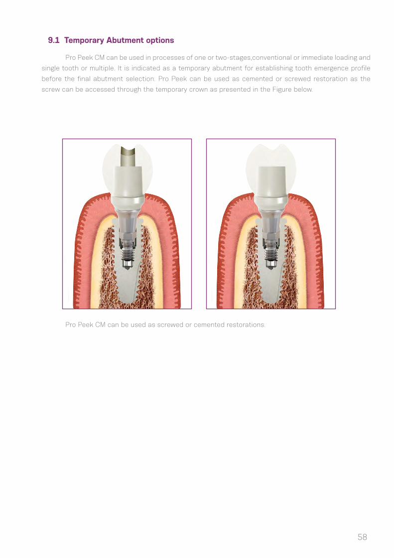
9.1 Temporary Abutment options
Pro Peek CM can be used in processes of one or two-stages,conventional or immediate loading and
single tooth or multiple. It is indicated as a temporary abutment for establishing tooth emergence profile
before the final abutment selection. Pro Peek can be used as cemented or screwed restoration as the
screw can be accessed through the temporary crown as presented in the Figure below.
Pro Peek CM can be used as screwed or cemented restorations.

59
The Neodent kits come in a cassette for organization and sterilization of the instruments. The
cassette is made of a shock-proof thermoplastic polymer, which is suitable for frequent sterilization in the
autoclave.
The Neodent kits should be sterilized the day before or on the day of the procedure. The
recommended is to follow the parameters for autoclave sterilization established by the norm BS EN ISO
17665-1: “Sterilization of health care products. Moist heat. Requirements for the development, validation
and routine control of a sterilization process for medical devices”.
Do not sterilize in dry heat , since the cassette will be damaged.
Validity for sterilization: 7 to 15 days, if stored in a clean dry environment, away from sunlight.
The Neodent kits and instruments should be cleaned thoroughly after each procedure. Do not
leave the instruments in a humid environment for long periods, since they may oxidize.
Step 1- Separate and disassemble the instruments (if this is the indication)
Step 2- Emerge completely in an enzymatic detergent solution (10%-15%)
Step 3- Wash cycle in an ultrasonic washer for 10 minutes
Step 4- Flush in distilled water to completely remove any residues, with the aid of brushes.
Step 5- Dry thoroughly with paper towels and/or compressed air
Step 6- Inspect the instruments to certify that the cleaning process has been effective
Step 7- Select the adequate packaging for the sterilization phase.
Important: do not leave or store the instruments if they are not completely dry, so as to avoid
oxidation. Do not use desincrustation solutions (non-enzymatic), since they may darken and oxidize the
instruments.
The use of enzymatic detergent solutions over 10%, and the inadequate removal of the solution
during the cleaning procedure may also favor oxidation.
10. NEODENT KITS
10.1 Sterilization
10.2 Cleaning and care of instruments
(1) Brånemark PI, Hansson BO, Adell R, Breine U, Lindström J, Hallén O et al Osseointegrated implants in the treatment of the edentulous jaw. Experience from a 10-year period. Scand J Plast Reconstr Surg Suppl. 1977;16:1-132.
(2) Gaviria L, Salcido JP, Guda T, Ong JL. Current trends in dental implants. J Korean Assoc Oral Maxillofac Surg. 2014 Apr;40(2):50-60.;
(3) Gupta A, Dhanraj M, Sivagami G.Status of surface treatment in endosseous implant: a literary overview. Indian J Dent Res. 2010 Jul-Sep;21(3):433-8.
(4) Lambert PM, Morris HF, Ochi S.Positive effect of surgical experience with implants on second-stage implant survival.J Oral Maxillofac Surg. 1997 Dec;55(12 Suppl 5):12-8.
(5) Bernardes SR, da Gloria Chiarello de Mattos M, Hobkirk J, Ribeiro RF.Loss of preload in screwed implant joints as a function of time and tightening/untightening sequences.Int J Oral Maxillofac Implants. 2014 Jan--Feb;29(1):89-96.
(6) Coppedê AR et al. Fracture resistance of the implant-abutment connection in implants with internal hex and internal conical connections under oblique compressive loading: an in vitro study. Int J Prosthodont. 2009 May-Jun;22(3):283-6.
(7) Lazzara RJ & Porter SS. Platform switching: A new concept in implant dentistry for controlling abutment restorative crestal bone levels. Int J Periodontics Restorative Dent 2006;26:9-17.
(8) Martin C, Thomé G, Melo AC, Fontão FN. Peri-implant bone response following immediate implants pla-ced in the esthetic zone and with immediate provisionalization-a case series study. Oral Maxillofac Surg 2015 Jun;19(2):157-63.
(9) Barros RR, Novaes AB Jr, Muglia VA, Lezzi G, Piattelli A.Influence of interimplant distances and place-ment depth on peri-implant bone remodeling of adjacent and immediately loaded Morse cone connection implants: a histomorphometric study in dogs Clin Oral Implants Res. 2010;21(4):371-8.
(10) Castro DS, Araujo MA, Benfatti CA, Araujo Cdos R, Piattelli A, Perrotti V, et al. Comparative histological and histomorphometrical evaluation of marginal bone resorption around external hexagon and Morse cone implants: an experimental study in dogs. Implant Dent 2014;23(3):270-6.
(11) Novaes AB Jr, Barros RR, Muglia VA, Borges GJ.Influence of interimplant distances and placement depth on papilla formation and crestal resorption: a clinical and radiographic study in dogs. J Oral Implantol 2009;35(1):18-27.
(12) Siqueira RAC. Avaliação do índice de sucesso e comportamento dos tecidos periimplantares de implantes cone morse equicrestais ou subcrestais em arcos inferiores.[master’s dissertation on internet].[Curitiba(Brazil)]: ILAPEO; 2013. [cited 28 out 2015] 126p. Available from: http://www.ilapeo.com.br/Monogra-fias_e_Dissertacoes/Dissertacoes_turma2011/Rafael_Amorin_Cavalcanti_de_Siqueira.pdf.
(13) Sotto-Maior BS, Lima Cde A, Senna PM, Camargos Gde V, Del Bel Cury AA. Biomechanical evaluation of subcrestal dental implants with different bone anchorages. Braz Oral Res 2014;28.
(14) dos Anjos CM, Harari ND, Reis RSA, Vidigal Junior GM. Análise in vitro da infiltração bacteriana na interface de pilares protéticos e implantes cone-morse / In vitro analysis of bacterial leakage at the interface between Morse taper implant platform and prosthetic abutments. ImplantNews;8(2):239-243, 2011.
BIBLIOGRAPHIC REFERENCES
60
(15) Sartoretto SC, Alves AT, Resende RF, Calasans-Maia J, Granjeiro JM, Calasans-Maia MD. Early os-seointegration driven by the surface chemistry and wettability of dental implants. J Appl Oral Sci. 2015 May--Jun;23(3):279-87.;
(16) Rupp F, Scheideler L, Eichler M, Geis-Gerstorfer J. Wetting behavior of dental implants. Int J Oral Maxil-lofac Implants. 2011 Nov-Dec; 26(6):1256-66.
(17) da Silveira BM. Análises tomográfica, microtomográfica e histológica entre enxertos em bloco autó-geno e xenógeno nas reconstruções ósseas de maxila. [master’s dissertation on internet].[Curitiba(Brazil)]: ILAPEO; 2013. [cited 15 jun 2014] 133p. Available from: http://www.ilapeo.com.br/biblioteca-detalhe/tomogra-phic-microtomographic-and-histological-analysis-between-grafts-in-autogenous-and-xenogeneic--C162410.html;
(18) Mendonça G, Mendonça BD, Oliveira SL, Araujo AC. Efeitos da diferenciação de células-tronco mesen-quimais humanas sobre superfícies de implantes hidrofílicas. ImplantNews 2013 Nov-Dez 10(6a):111-116.
(19) Glauser R, Portmann M, Ruhstaller P. Initial implant stability using different implant designs and surgi-cal techniques. Appl Osseointeg Res. 2001;2(1):6-8.
(20) da Cunha HA, Francischone CE, Filho HN, de Oliveira RC. A comparison between cutting torque and resonance frequency in the assessment of primary stability and final torque capacity of standard and TiUnite single-tooth implants under immediate loading. Int J Oral Maxillofac Implants. 2004 Jul-Aug;19(4):578-85.
61