Embed Size (px)
Citation preview

l.Q39194 [ 00 --=t L, l 13 \.-\]
DOE/RL-2011-59 Revision 0
Surveillance and Maintenance Plan for the Plutonium Finishing Plant Complex
Prepared for the U.S. Department of Energy Assistant Secretary for Environmental Management
8ENERGY ~~:nd Operations
P.O. Box 550 Richland, Washington 99352
Approved for Public Release; Further Dissemination Unlimited
JUL 2 4 2018 ~ EDMC

DOE/RL-2011-59 Revision 0
Surveillance and Maintenance Plan for the Plutonium Finishing Plant Complex
Date Published June 2016
Prepared for the U.S. Department of Energy Assistant Secretary for Environmental Management
8 ENERGY ~#.:nd Operations
P.O. Box 550 Richland, Washington 99352
Release Approval
APPROVED By Julia Raymer at 8:43 am, Jun 13, 2016
Date
Approved for Public Release; Further Dissemination Unlimited

TRADEMARK DISCLAIMER Reference herein to any spec1f1c commercial product, process, or service by tradename, trademark, manufacturer, or otherwise, does not necessarily constitute or imply its endorsement, recommendation , or favoring by the United States Government or any agency thereof or its contractors or subcontractors.
This report has been reproduced from the best available copy.
Printed in the United States of America
DOE/RL-2011-59 Revision 0

Title
2
DOE/RL-2011 -59, REV. 0
Signature Sheet
Surveillance and Maintenance Plan for the Plutonium Finishing Plant Complex
Ray J. Corey, Assistant Manager for the River and Plateau U.S. Department of Energy, Richland Operations Office
Stephanie Schleif, Nuclear Waste Program Washington State Department of Ecology
iii
<.o{llo/ll a Date

2
3
DOE/RL-2011-59, REV. 0
This page intentionally left blank.
iv

DOE/RL-2011-59, REV. 0
Contents
2 1 Introduction ....................................................................................................................................... 1
3 1.1 History and Background .... .......... .. ....... .... .. .. ....... .. ........ .. ........ ...... .... ... .............. ... ........ .... .. ...... 2
4 1.2 Milestones ... ...................... ...... ............... .. .... .......... ........ .. .. ................. ... ....... ........... .. .. ... ..... .. ... 3
5 1.3 Purpose and Scope .... ....................................... .. .. ............. ........ .. ............... .. ........... ....... ... ... ...... 3
6 1.4 Plan Objectives ............... ............. ....... ...... .... .................... ..... .. ............... .... ... ..... .. ...... ............... 5
7 2 Plutonium Finishing Plant Complex Information .......................................................................... 5
8 2.1 Stage 1 S&M Expected Conditions and Activities ......... ... .... ....... .............................. ............... 6
9 2.2 Stage 2 S&M Expected Conditions .............. .. .......................... ........................ ... .. .. ....... ... .... .... 7
10
11
12
2.2.1 234-52 Plutonium Fabrication Facility ........... ... ... .... .. ...... ... ......... ... ........... .. ... ... ........... 8
2.2.2 291-Z Exhaust Air Filter Stack Building Description ........ ..... .... ....... ... ... .. .. ... .. .. ...... ..... 8
2.2.3 24 1-Z Tank Cells Description ........ .. ................. ..... .... .... .. ... .. ... ... .. ...... ..... ........ .... ........ 10
13 2.3 Stage 2 S&M Activities .. .. ...... ............. .... ... ....... ... .. ........ .... ... .......... ...... .... .. ... ...... .................. . I 0
14 2.4 Stage 2 S&M Routine S&M ........ ..... ... ............................................. .. ..................................... 11
15 2.5 Types of PFP Complex Surveillance and Maintenance .... .. ..... ... .... .. ... ......... ..... ..... .... ..... ... ... . 12
16 2.5.1 General Inspection ................. ....... ......... .. .. .. ..... ....... .. .... .. ... ... .. .... .......... ... ........... ...... .. 12
17 2.5 .2 Maintenance Activities ....... ..... ........ .......................... .... ....... .... ... ............... .... ..... ... ..... 12
18 3 Quality Assurance ................................ ........................................................................... ................ 12
19 4 Training and Qualifications ........................................................................................................... 12
20 5 Environmental Compliance/Protection ................................ ........ ........................... .... .................. 13
21 5 .1 Stage 1 S&M Radiological Air Emissions ... .. .... .... ......... ..... ... ... ........ ........... ... ..................... .. 13
22 5.2 Stage 2 S&M Radiological Air Emi ssions ... .. .. ....... ....... ......... ... ..... ................... ..................... 13
23 5.2.1 Airborne Source Infonnation .......................... .................................. .. ......................... 13
24 5.2.2 Potential Annual Emissions ....................... ......... ..... ... .......... .... ................................... 13
25 5.2.3 Airborne Emission Controls ...... ... ........... ... .... ..... ................. ............................. ........... 14
26 5 .2.4 Airborne Emission Monitoring .... ............ ...... .... .. ... ............ .. ... ...... ...... .... ...... .. ........... . 14
27 5.3 Waste Management .... ... ..... ... ......... ........ ................ .. ............. ..... ..... .. ..... ... .... ... ............... ..... ... 14
28 5.4 Hazardous Material Management ..... .. ... .. ............. ... ...... .... ... .. .... ....... .... ... ........... ...... .. .. ..... .... . 15
29 5.5 Record Keeping and Documentation ... .. ... ... .. ....... .. .... .. ........ ........ ............................. ... ...... ..... 15
30 6 Radiological Controls ...................................................................................................................... 16
31 7 Emergency Management and Preparedness .................................. ............................................... 16
32 8 Health and Safety ................................ ............................. .. ............................................................. 16
33 9 Institutional Controls .................. .................................................................................................... 17
34 10 Safeguards and Security ................................................................................................................. 17
35 11 Schedule ...................................................................................................................................... .. ... 17
36 12 References ........ ................................ ................................................................................................ 17
V

DOE/RL-2011-59, REV. 0
Figures
2 Figure 1. Slabs and Underground Structures in S&M Area ...... .. ... .. .. .... ..... ...... ..... .. .... ............... ... .. ... ... I
3 Figure 2. 234-5Z Pipe Tunnels and Pipe Trenches ........ .... ... .. .. ..... ........... .. .. ........ .... .... .......... ...... ... .. .... 9
4 Figure 3. Cutaway View of the 291 -Z Exhaust Fan and Compressor House ........... ...... .. .. .. .... ... ....... .. 10
5 Figure 4. 241-Z Building Cutaway View ..... .... .. ....... ........ .. .... .. .... ..... ...... .. ..... ... .......... .. ... .... .. .... ... ..... . I I
6 Figure 5. Near-Facility Ambient Air Monitoring (Typical) ...... ............... ..... ..... ... ......... ......... ... .. ... ..... 15
7 Tables
8 Table I . Building Slabs .... ..... .. ............ ... .. ... .. ... ....... ... .. ... .. ........ ...... ..... ......... .. .. .. ..... ............................. 3
9 Table 2. Underground Structures ........ ... ... .... ... .. ... .... ........... ...... ... .. .. ... .... ...... ... ... .... .. ... ..... .... .. .... ....... .. 4
10
vi

ALARA
ARAR
CERCLA
D4
DOE
Ecology
EPA
EPCC
HASP
HEPA
IC
OU
PFP
QA
RAR
RAWP
RCT
Rl/FS
S&M
Tri-Party Agreement
TRU
URMA
WIDS
2
DOE/RL-2011-59, REV. 0
Terms
as low as reasonably achievable
applicable or relevant and appropriate requirement
Comprehensive Environmental Response, Compensation, and Liability Act of 1980
deactivation, decontamination, decommissioning, and demolition
U.S. Department of Energy
Washington State Department of Ecology
U.S. Environmental Protection Agency
end point criteria checklist
health and safety plan
high-efficiency particulate air
institutional control
operable unit
Plutonium Finishing Plant
quality assurance
removal action report
removal action work plan
radiological control technician
remedial investigation/feasibility study
surveillance and maintenance
Hanford Federal Facility Agreement and Consent Order
transuranic
underground radioactive material area
Waste Infonnation Data System
vii

DOE/RL-2011 -59, REV. 0
2 This page intentionally left blank.
vi ii
DOE/RL-2011 -59, REV. 0
1 Introduction
2 This Surveillance and Maintenance (S&M) Plan describes the expected conditions of the Plutonium 3 Finishing Plant (PFP) at the beginning of the S&M phase and the actions necessary to maintain safe and 4 stable conditions, as identified in Tri-Party Agreement Milestone M-83-20 (Ecology et al. , 1989a, 5 Hanford Federal Facility Agreement and Consent Order) and associated end point criteria in 6 HNF-2240 I, Plutonium Finishing Plant (PFP) Complex End Point Criteria, until implementation of 7 future remedial actions. This S&M Plan is being submitted as a primary document to the Washington 8 State Department of Ecology (Ecology) as the lead regulatory agency for S&M. The activities addressed 9 by this S&M plan are applicable to the area within the fence indicated in Figure I .
10
I I
Jr
r-l'/-4'-l--lf-lf--/;f-,/f-Jl'-I--H-H---,ff-,!f------3-Jf-1-H-l7
i ! j -J
f B O ""'~l T LJ ! r ~ J ~1~1 ~ rj~ 2503-Z J
2734- ZK 252-2-1 267Z
0 50' 100' 150' 250'
(APPROXI l.1 ATE)
Figure 1. Slabs and Underground Structures in S&M Area

DOE/RL-2011-59, REV. 0
1.1 History and Background
2 PFP is located on the Central Plateau of the Hanford Site, within the 200 West Area. The PFP Complex 3 included several process and support buildings constructed in 1949 through 1993 that were used to 4 process plutonium solutions or oxides into hockey puck sized plutonium metal "buttons" for shipment to 5 the nation's nuclear weapons production facilities, or the oxide was used to fabricate mixed-oxide reactor 6 fuel. In 1991, the mission changed to plutonium-bearing material stabilization and deactivation and 7 decommissioning. Material stabilization campaigns and the mission for storage of stabilized plutonium 8 materials were completed in December 2009 when the final containers of stored material were shipped 9 from PFP.
10 The Tri-Party Agreement Action Plan (Ecology et al., 1989b, Hanford Federal Facility Agreement and 11 Consent Order Action Plan) identifies the PFP Complex as a key facility. Thus, it is subject to the 12 disposition process of Section 8.0 of the Action Plan. The PFP Complex will be dispositioned under the 13 Comprehensive Environmental Response, Compensation, and Liability Act of 1980 (CERCLA). Potential 14 removal action alternatives for buildings and other structures at the PFP Complex were evaluated in 15 DOE/RL-2004-05, Engineering Evaluation/Cost Analysis for the Plutonium Finishing Plant 16 Above-Grade Structures. The preferred alternative is documented in DOE/RL-2005- 13, Action 17 Memorandum for the Plutonium Finishing Plant Above-Grade Structures Non-Time Critical Removal 18 Action (hereinafter referred to as the Action Memorandum). The selected alternative is demolition of 19 above-grade structures to slab-on-grade, suitable for low cost S&M pending final disposition of the area. 20 Implementation of the selected alternative is described in DOE/RL-20 I 1-03, Removal Action Work Plan 21 for the Deactivation, Decontamination, Decommissioning, and Demolition of the Plutonium Finishing 22 Plant Complex (hereinafter referred to as the removal action work plan [RA WP]).
23 The CERCLA documents cited previously define and make a distinction between the tenns above-grade, 24 sub-grade, and below-grade for the purpose of defining the scope of the removal action. When those 25 tenns are used in this document, it is within the context of the CERCLA documents 1. The tenn 26 underground, as used in this document, encompasses sub-grade and below-grade items and includes 27 building slabs remaining after building demolition.
28 The U.S. Department of Energy (DOE) is the lead agency for CERCLA actions. Ecology is the lead 29 regulatory agency for the removal action and S&M. As part of the completion process of the removal 30 action, the remaining components will be evaluated and assigned to the appropriate operable unit (OU) in 31 accordance with existing Tri-Party Agreement procedures. Dependent on the OU assignment, Ecology or 32 the U.S. Environmental Protection Agency (EPA) may be the lead regulatory agency for final remedial 33 actions at the PFP Complex .
1 The term above-grade in this document refers to items that are above or on the elevation of the surrounding ground (e.g., a building or concrete slab). The term below-grade means below the elevation of the surrounding ground but not completely covered by soil. For example, the basement of a building would be below-grade. The term sub-grade is used when referring on an item that is completely covered by soil or other covering (e.g., a floor slab) that is not readily removed . For example, piping that is buried under a building is considered sub-grade.
2

DOE/RL-2011 -59, REV. 0
1.2 Milestones
2 Tri-Party Agreement Major Milestone M-083-00A, Proposed Tri-Party Agreement Modifications and 3 Ref erence Documents for Plutonium Finishing Plant Transition and Selected Disposition Milestones 4 (M-83-00A) , (Ecology et al. , 1989a, Hanford Federal Facility Agreement and Consent Order) , has three 5 key elements:
6 1. "Completion of all activities necessary to achieve end point criteria established through 7 Milestone M-83-20 for placing the PFP facility in a safe and stable S&M mode."
8 2. "Completion of all activities described in the approved M-83 series interim milestones and 9 target date."
10 3. "Completion of the balance of PFP selected disposition activities pursuant to the final action 11 memoranda and work plans."
12 Upon completion of Milestone M-083-00A, PFP will transition to S&M under this S&M Plan, which was 13 developed in accordance with Target Milestone M-083-24-T0 1.
14 In late 2015 , Ecology and the DOE, Richland Operations Office agreed on removal of slabs for the 15 236-Z and 242-Z Buildings, following removal of the above-grade structures, to reduce potential residual 16 radiological inventory in the PFP Complex area . The RA WP (DOE/RL-2011 -03) and End Point Criteria 17 document (HNF-2240 I) were updated using Tri-Party Agreement change notices (TPA-CN-681 and 18 TPA-CN-682, respectively) to allow this change. Consequently, this plan describes an S&M phase with 19 two distinct stages: an initial stage where post-transition actions , such as slab removal , will take place to 20 reduce hazards further, and a caretaker stage pending final remedial action. These stages are further 21 described in Chapter 2 of this plan .
22 1.3 Purpose and Scope
23 The purpose of this S&M Plan is to identify actions necessary to maintain safe and stable conditions until 24 implementation of future remedial actions. The scope of this plan is limited to S&M of the items listed in 25 Tables I and 2 within the fenced area shown in Figure 1. The east side of the PFP Complex ( outside the 26 fenced area) is the support area. This area contains mobile offices, parking lots, the 2607-WA Septic 27 System (southwest comer of the intersection of 19th Street and Camden Avenue), and the 212-Z Lag 28 Storage Yard. The mobile offices, parking lots, 212-Z lag storage yard, and septic system will remain 29 active for an extended period and are not addressed by this S&M Plan. The 24 l-Z-361 tank, while inside 30 the fence , has been included in the 200-PW-1/3/6 OU remedial action (EPA et al. , 2011 , Record 31 of Decision Hanford 200 Area Superfund Site 200-CW-5 and 200-PW-J, 200-PW-3, and 32 200-PW-6 Operable Units) and, therefore, is not included in this S&M Plan.
33 The scope of this plan may be modified in accordance with the Tri-Party Agreement process for primary 34 document changes as items transition from active to inactive status or transition to coverage under other 35 documents. Activities perfonned according to this S&M Plan will be conducted in accordance with 36 applicable or relevant and appropriate requirements (ARARs) under CERCLA authorization.
Table 1. Building Slabs
Identification Description Identification Description
232-Z Waste Incinerator Facility 267-Z Fire Riser Valve House
234-SZ Plutonium Fabrication Facility 296-Z-3 241-Z Stack
3

DOE/RL-2011-59 , REV. 0
Table 1. Building Slabs
Identification Description Identification Description
234-5ZA Change Room Addition 2721 -Z Emergency Generator Building
234-ZB Clean Special Work Permit
2727-Z Supply Storage Building (Protective Clothing) Storage
234-ZC Barrel Storage 2729-Z Maintenance Storage Building
236-Z Plutonium Reclamation Facility (slab
2731 -Z Plutonium Drum Storage Building to be removed during Stage 1 S&M)
241 -Z Tank Farm Waste Disposal Building Not numbered Construction Forces Buildings
241-ZA Sample Building 2731 -ZA Container Storage Bui lding
2734-ZA, -ZB, 241-ZB Sodium Hydroxide Tank -ZC, -ZD, -ZF, Gas Bottle Storage
-ZG, -ZK
241-ZG Change Facility 2734-ZJ Liquid Nitrogen Storage and Supply
242-Z Waste Treatment Facility (Slab to Be
2734-ZL Hydrogen Fluoride Facility Removed during Stage I S&M)
243-Z Low-Level Waste Treatment Facility 2735-Z Bulk Chemical Storage Tanks
243-ZB Cooling Towers 2736-Z Plutonium Storage Building
252-Z-l E lectrical Substation 2736-ZA Plutonium Storage Ventilation Structure
270-Z Operations and Support Facility 2736-ZB Plutonium Storage Support Facility
2503-Z Electrical Switchyard 2736-ZC Cargo Restraint Transport Dock
2701 -ZA Central Alann Station 2902-Z Water Tower
Table 2. Underground Structures
Structure Identification Name/Description Status During Stage 2 S&M
232-Z Ventilation Duct 232-Z to 291-Z Venti lation Duct Filled with grout
236-Z Ventilation Duct 236-Z to 291 -Z Ventilation Duct Sealed at each end
234-5Z Pipe Tunnels Filled with backfill material
241 -Z Tank Farm Waste Disposal Building Vaults and tanks remain (Section 2.2.3)
241-Z Pipe Trench 241 -Z Pipe Trench Depth ranges from approximately 1.5 m (5 ft) to approximately 2.1 m (7 ft)
241 -Z-RB Retention Basin and Valve Pit Both fi lled with grout
243-ZA Low-Level Waste Storage Tanks
Filled with backfill (tanks removed) Sump
4

DOE/RL-20 11 -59, REV. 0
Table 2. Underground Structures
Structure Identification Name/Description Status During Stage 2 S&M -------I
291-Z Ventilation Fan Building Filled with backfill material
291-Z-l Stack and Monitoring Building Base of stack {elbow) remain. Filled with backfi II material.
2902-Z Valve Pit Filled with grout
2 1.4 Plan Objectives
3 Objectives of the S&M program, as enumerated in DOE G 430.1-2, Implementation Guide for 4 Surveillance and Maintenance during Facility Transition and Disposition, are as follows:
5 • Ensure adequate containment of remaining radioactive and hazardous material.
6 • Provide security control for access to the area and physical safety to surveillance personnel.
7 • Maintain remaining components in a manner that will minimize potential hazards to the public, 8 environment, and surveillance personnel.
9 • Provide a plan for identification and compliance with applicable environmental, safety, health, and IO security requirements .
11 2 Plutonium Finishing Plant Complex Information
12 Information related to the deactivation, decontamination, decommissioning, and demolition (D4) of the 13 PFP Complex will be available to guide activities undertaken during the S&M phase and to support the 14 process for detennining the final CERCLA remedial action. Key documents include the following:
15 • End point criteria checklists (EPCCs)-These checklists identify the actions required to complete D4 16 for specific bui ldings and the PFP Complex area inside the boundary fence to comply with the end 17 point criteria defined in HNF-2240 I . The EPCC documents specify which actions will be completed 18 prior to transition to the S&M phase (pre-transition) and which actions will be completed after 19 transition to the S&M phase (post-transition) . Documentation supporting pre-transition end point 20 completion will be incorporated into EPCC documents upon completion of the relevant pre-transition 21 actions. Similarly, the checklist documents will also incorporate documentation of post-transition 22 actions when completed. The EPCCs for pre-transition will aid the S&M organization during the 23 initial stage of S&M. EPCCs from post-transition will aid the S&M organization during Stage 2 of 24 S&M.
25 • Removal action report (RAR)- This report documents the review described in Section 5. 7 of the 26 RA WP (DOE/RL-2011 -03). The RAR documents the end state of the PFP Complex after D4 and 27 validates that the Action Memorandum (DOE/RL-2005-13) is completed, the S&M Plan is approved, 28 the property is turned over to S&M (for long-tenn care following completion of post-transition 29 actions), and appropriate documents are incorporated into the Administrative Record . Two RARs will 30 be developed, one to document completion of pre-transition actions, followed by another RAR upon 31 completion of post-transition actions.
32 • S&M turnover package- This package is compiled following completion of post-transition actions 33 for use by the S&M organization during the second stage of the S&M phase. It includes essential
5

DOE/RL-2011-59, REV. 0
drawings, available characterization information, location and condition of remaining features, and 2 similar information of particular importance during longer tenn S&M.
3 2.1 Stage 1 S&M Expected Conditions and Activities
4 At the time of transition to S&M, all end point criteria pre-transition actions will have been completed. 5 Documentation verifying completion will be provided in appendices to each of the EPCC documents . 6 A brief summary of expected conditions at the beginning of Stage I S&M follows:
7 • Process and storage facilities, and their supporting ancillary structures, will have been removed to 8 slab on grade.
9 • Areas with residual radioactive contamination will have been placed in a safe and stable condition IO that satisfies underground radioactive material area (URMA) requirements.
I I • Radiological and other required postings (e.g., vehicle exclusion areas and confined spaces) will be 12 in place.
13 • Hazardous materials and transuranic (TRU) wastes will have been removed from accessible I 4 below-grade spaces.
15 • Ventilation ducting will have been isolated and sealed at building boundaries.
I 6 • Buried piping that entered or exited buildings will have been checked for liquids and drained 17 if needed.
18 • Process drains to 243Z/ZA will have been flushed.
19 • The 241 Z RCRA unit will have been clean closed (see Section 2.2.3).
20 • Drain lines, vents, and penetrations will have been isolated and sealed.
2 I • No plutonium that poses a significant security risk or criticality potential will remain in underground 22 systems.
23 • Unattached materials and equipment in below-grade spaces in buildings will have been removed and 24 the space stabilized to prevent release of contamination and structural collapse.
25 • Manhole covers to inactive systems will be isolated or sealed to prevent water intrusion and removal 26 from confined space listing.
27 • PFP Complex electrical supply will be isolated at a point minimizing dead legs.
28 • Septic tanks 2607-Z and 2607-Zl will be backfilled.
29 • Above-grade steam lines will be removed.
30 • Inactive PFP Complex utility poles will be removed.
3 I • TRU waste (e.g., equipment, piping, and ducting) in accessible below-grade spaces will have been 32 removed or decontaminated to the point that remaining equipment, piping, and ducting could be 33 dispositioned as low-level waste.
6

DOE/RL-2011-59, REV. 0
During Stage 1 S&M, slab removal and other EPC post-transition actions will take place. The following 2 is a summary of actions that will be conducted in accordance with the RA WP (DOE/RL-2011-03) .
3 • Remove 242-Z and 236-Z slabs.
4 • Finalize characterization data for remaining tubing, piping, ducting, and drain lines and identify and 5 label those containing contamination.
6 • Remove, fix , and contain any radiological contamination.
7 • Install contamination control caps where required.
8 • Perfonn final radiological survey to document radiological conditions.
9 • Remove miscellaneous above-grade structures and materials.
10 • Remove and dispose of waste and verify/document elimination of waste accumulation areas.
11 • Isolate the PFP Complex water supply at a point minimizing isolation points and dead legs.
12 • Grade soil to promote drainage away from below-grade structures.
13 • Stabilize soil to mitigate dust and erosion.
14 • Provide posting as needed (e.g. , radiological , confined space, vehicle restrictions).
15 • Provide controls to prevent unauthorized access.
16 • Compile documentation for remaining industrial hazards, radiological issues, and hazardous 17 substances.
18 • Develop S&M procedures.
19 • Fulfill remaining RA WP (DOE/RL-2011-03) and End Point Criteria document (HNF-22401) 20 regulatory commitments, and prepare regulatory documentation.
21 2.2 Stage 2 S&M Expected Conditions
22 Following completion of remaining RA WP and end point criteria document requirements, the PFP 23 Complex will transition to Stage 2 S&M (i.e., long-term S&M pending final remediation). All remaining 24 components (structure slabs, underground portions of the original structures, pipelines, tanks, and 25 potentially contaminated soi l below or around the original structures) will be evaluated under the 26 CERCLA process to detennine potential threats to human health and the environment and, if detennined 27 to need further action, assigned to an OU and added to Appendix C of the Tri-Party Agreement Action 28 Plan (Ecology et al. , 1989b ).
29 The area subject to this S&M Plan will be controlled with a continuous chain link fence with locked 30 access points. High mast lights may remain in place. The following active structures and equipment will 31 remain in place and are not covered by this S&M Plan:
32 • 2702-Z cell tower and support building, along with associated active utility poles
33 • 2607-Z-1 sewage lift station and associated main sewer line through the PFP Complex
34 • Groundwater monitoring wel l 299-W 15-42
7

DOE/RL-20 11 -59, REV. 0
Actions taken during Stage 1 S&M will facilitate an S&M program that will require minimal resources to 2 execute. Radioactive contamination will be maintained in URMAs with a robust contamination control 3 cap, where needed, and the area will be graded to promote drainage. Posting and labeling ofremaining 4 hazards will have been completed. Void spaces will have been identified, posted, and stabilized as 5 necessary or backfilled to prevent structural collapse.
6 Table I provides a list of building slabs that are expected to remain, and Table 2 provides a list of 7 underground structures. Figure I provides the location of slabs and underground structures.
8 Slabs and underground structures and components left in place may be covered by one or more 9 contamination control covers, in accordance with the RA WP (DOE/RL-2011-03) and End Point Criteria
IO document (HNF-22401), and will be stabi lized to meet URMA requirements. In the case of232-Z 11 and 236-Z, there are underground ventilation ducts that go to the 291 -Z exhaust facility. 12 The 2704-Z safeguards and security building is not included in this list because there is no slab associated 13 with this building.
14 Underground portions of the 234-52, 241 -Z, and 291-Z Buildings will be left in a configuration such that 15 human entry will not be possible, thus minimizing S&M of these locations. Other significant underground 16 structures in this area include the 232-Z underground ventilation duct, 236-Z underground ventilation 17 duct, 241 -Z-RB retention basin and valve pit, 243 -ZA sump, and 2902-Z valve pit. If not removed with 18 the slab, the piping and exhaust ducts under 236-Z (H-2-29620, Structural Concrete Foundation Plan & 19 Details) would remain in place. The fo llowing subsections provide infonnation about the major 20 underground structures from Table 2. (NOTE: Turnover packages and other documentation, described at 21 the beginning of Chapter 2, will provide additional detail s.)
22 2.2.1 234-SZ Plutonium Fabrication Facility 23 The main plutonium processing facility was 234-5Z. The first floor slab and basement are constructed of 24 reinforced poured concrete. The basement consists of pipe tunnels (Figure 2). Pipe trenches that connect 25 to the pipe tunnels are embedded in the slab and will have been filled with grout prior to transition to 26 S&M. All materials that require disposition as TRU waste will have been removed from the tunnels, and 27 they will be filled with backfill prior to transition to S&M. There will be no access to the pipe tunnels 28 during S&M because the doors will have been sealed, and the tunnels and stairwells will have 29 been backfilled.
30 2.2.2 291-Z Exhaust Air Filter Stack Building Description 31 A cutaway of the 291 -Z exhaust fan and compressor house is shown in Figure 3. Most of 32 the 291-Z Building is underground and will remain in place. Prior to transition to S&M, above-grade 33 ductwork from 234-5Z and the roof of 291-Z will be removed. Segments of the 66 cm (26 in.) vacuum 34 line that require disposition as TRU waste will have been removed. The walls will be removed down to 35 existing grade. Asbestos and other hazardous materials will have been removed, but the fans and other 36 equipment will remain in place. The structure including access stairs will be filled with backfill. The air 37 ducts (plenums) under 291 -Z will not be void filled , but the duct will be filled with backfill at the vertical 38 transition point to the stack after stack removal.
8

.K LEGEND
t • ~
. •--
0 0 m ;o r
"' 0 c.o I L ~~ 4;;;1 9 ll 4.::.1.4 II II 4-2 4- 1 n 1~1 ,-.. 1-2 I I ...... - - - - - n ......
I ()l
~ :::0 m :< 0
2 Figure 2. 234-SZ Pipe Tunnels and Pipe Trenches

Electric Fans
Discharge from 232·2
DOE/RL-2011-59, REV. 0
291-Z-1 Stack
I 2 Figure 3. Cutaway View of the 291-Z Exhaust Fan and Compressor House
3 2.2.3 241-Z Tank Cells Description 4 The 241 -Z Liquid Waste Treatment Facility was a reinforced concrete structure with below-grade vaults 5 and tanks (Figure 4). This facility , which was pennitted under the Resource Conservation and Recovery 6 Act of 1976, was clean closed per the RCRA Closure plan (DOE/RL-96-82) and the above-grade portion 7 of the building was demolished in 2007 . Drain lines that were part of the 241 -Z RCRA unit going to 241 Z 8 have also been clean closed. All drain lines entering 241 Z have been verified empty at 241 Z.
9 The remaining underground structure consists of five separate cells (vaults), each containing a 16,277.3 L l O (4,300 gal) tank. The tanks were cleaned out and stabilized as part of the facility deactivation and closure; 11 HNF-33999, 241-Z As Left Characterization , provides a detailed description of conditions. The cell 12 access hatches are sealed and covered with grout and gravel. The cell for the TK-D6 tank has about 0.6 m 13 (2 ft) of grout in the bottom. The underground cells, tanks, and associated piping remain in place. 14 A concrete contamination control cover was placed over the underground portion of the structure in 2007.
1 s 2.3 Stage 2 S&M Activities
16 Stage 2 S&M will include actions to keep the PFP Complex area in a safe and stable condition pending 17 final remediation. The focus will be on ensuring that contamination control measures remain in place to 18 avoid the spread of contamination, but actions may be taken to reduce hazards further or minimize 19 S&M costs.
10

1
2
DOE/RL-2011 -59, REV. 0
Figure 4. 241 -Z Building Cutaway View
3 Activities associated with future remedial action for the PFP Complex (e.g. , remedial
~11°'J0ll•S9_ID_0 1.i-1
4 investigation/feasibility study [Rl/FS] process) will be conducted under remedial action authority and will 5 not be addressed by this S&M Plan.
6 2.4 Stage 2 S&M Routine S&M
7 Routine S&M will consist of perfonning an annual surveillance of the area , within the scope of this 8 S&M Plan to verify that conditions have not changed, and will address actions necessary to resolve issues 9 as identified. The primary focus will be to perfom1 radiological surveys to ensure that no contamination
IO from URMAs has migrated to the surface. The surveillance will identify indications of changed site 11 conditions, such as subsidence or vegetation changes. Signs or other postings and security features will 12 also be checked to ensure that appropriate controls are in place and remain effective.
13 The primary S&M activity for the PFP Complex is periodic surveillance to ensure that structural integrity 14 and hazardous substance confinement is maintained. The surveillance frequency is annual but may be 15 adjusted later based on actual inspection history. Routine S&M activities will include periodic general 16 inspections, radiological surveys, erosion control, pest control , vegetation and weed control, and 17 specialized inspections (e.g. , covers over underground structures remain sound). Nonroutine activities 18 may include necessary repair work on installed covers. These activities are addressed in the 19 following subsections.
11

DOE/RL-2011 -59, REV. 0
2.5 Types of PFP Complex Surveillance and Maintenance
2 A proper balance of corrective and preventive maintenance is employed to provide confidence that 3 degradation of controls, if any, is identified, corrected and documented. This section summarizes the 4 types of S&M conducted during the Stage 2 S&M phase of the PFP Complex.
5 2.5.1 General Inspection 6 An annual inspection will be conducted to determine how site conditions have changed from the initial 7 site transfer and from the previous inspection. Changes identified during the annual inspection will be 8 evaluated to determine if maintenance or repair activities are necessary. These annual inspections will 9 include the following elements.
10
11
12
13
14
I 5
16
17
18
19
20 21
22
23
24
25
• • • • • • • • • • • • • • • •
Fence condition and access controls
Slab and cover condition
Postings
Evidence of contamination migration
Erosion control
Suspect hazardous materials
Hazardous conditions
Excess combustible materials
Excess equipment or material
Ground subsidence
Housekeeping
Occupational hazards
Previously unidentified hazards
Unidentified or unlabeled containers
Animal or insect intrusion
Vegetation and weed control
26 2.5.2 Maintenance Activities 27 Deficiencies identified during surveillance activities will be evaluated, and corrective maintenance will be 28 planned, implemented, and documented, as needed. Preventive maintenance activities may include, but are 29 not limited to, regular herbicide application, slab resealing, pesticide application, tumbleweed and loose 30 vegetation removal , and fence repair.
31 3 Quality Assurance
32 Activities perfonned during S&M that will require implementation of quality assurance principles and 33 processes (e.g. , inspections, periodic maintenance) will be planned and implemented in a graded 34 approach, based on the potential effect on the environment, safety, health , reliability, and continuity of 35 operations. Quality assurance requirements in effect at the time of perfonnance of the work, and as 36 identified in the Contractor's contract, will be followed.
37 4 Training and Qualifications
38 The company ' s training program wi ll provide workers with the knowledge and skills necessary to execute 39 assigned duties safely. A graded approach is used to ensure that workers receive a level of training
12

DOE/RL-2011-59, REV. 0
commensurate with their responsibility. During Stage I S&M activities, workers will meet the training 2 and qualification requirements outlined in the RA WP (DOE/RL-20 I 1-03). Thereafter, training 3 requirements will be established based on the complexity and risk associated with the work being 4 perfonned. Routine surveillance activities will typically require training in the following areas:
5 • Radiological worker
6 • Site-specific conditions and hazards
7 • Potential emergency conditions and appropriate responses
8 • Waste management
9 • Job-specific duties and responsibilities
10 5 Environmental Compliance/Protection
11 During Stage 1 of the PFP S&M phase, actions will be conducted in accordance with the ARARs and 12 other provisions of the RA WP (DOE/RL-2011-03) . After completion of the post-transition actions and 13 initiation of Stage 2 S&M, enviromnental compliance will transition to CERCLA authority for the 14 investigative phase of the remedial action process. Record keeping and document control will be 15 maintained for all field activities conducted.
16 5.1 Stage 1 S&M Radiological Air Emissions
17 Slab removal (i .e. , 236-Z and 242-Z slabs) presents the most significant potential for radioactive air 18 emissions after slab-on-grade conditions are achieved. Air dispersion modeling will be performed to 19 evaluate potential emissions from slab removal. Other S&M activities, such as excavating and backfilling, 20 have the potential to release radioactive contaminants into the air. Emissions will be kept as low as 21 reasonably achievable (ALARA) and will be appropriately monitored by applying the controls identified 22 in Section 4.3 .1.2 of the RA WP (DOE/RL-2011 -03).
23 5.2 Stage 2 S&M Radiological Air Emissions
24 After slab removal and completion of remaining RA WP and End Point Criteria document requirements, 25 S&M activities at the PFP Complex will have low potential for generating airborne contamination. 26 Building belowgrade spaces (e.g. , basements) will be sealed to preclude entry, and slabs with remaining 27 radiological contamination will be fixed and covered .
28 5.2.1 Airborne Source Information 29 Potential emissions from the PFP Complex would mainly be diffuse and fugitive from the general area. 30 If used during S&M, portable temporary radioactive air emission units would represent point sources.
31 The primary radionuclides of concern are americium-241 and plutonium-238, -239, -240, -241, and -242. 32 Other radioisotopes may be present because of activation products, fission products, and decay products. 33 The remaining contamination associated with PFP demolition will be stabilized in underground spaces 34 or slabs.
35 5.2.2 Potential Annual Emissions 36 Other than site maintenance activities, there are no planned active S&M processes or anticipated 37 disturbances of the remaining radiological material that could cause meaningful emissions. Underground 38 spaces (building basements) left after the current removal action will be sealed, and contamination 39 remaining on building slabs will be fixed and covered with a contamination control cover. Therefore, the 40 PFP Complex will represent a minor emissions area source during Stage 2 S&M. The annual unabated
13

DOE/RL-2011-59, REV. 0
I potential-to-emit and resultant effective dose calculations for the maximally exposed individual from 2 diffuse and fugitive sources associated with Stage 2 S&M is anticipated to be much less than 3 0. I mrem/yr.
4 Activities such as sampling, excavation, or other required intrusive work would need to be evaluated for 5 air emissions and appropriate monitoring and controls, based on the site-specific conditions prior to 6 performing the work.
7 5.2.3 Airborne Emission Controls 8 Based on analysis of the potential emissions and evaluation of available control technologies, the 9 following controls of diffuse and fugitive emissions have been selected for use during S&M activities:
IO • Water will be applied in the most effective method, as needed, for suppression of fugitive emissions 11 and dust.
12 • Radiological surveys (e.g. , smear samples) will be taken of external areas where there is the potential 13 for emissions.
14 • Appropriate controls such as fixatives , covers, containment tents, windscreens, or other controls will 15 be applied, if needed, as determined by the radiological control organization, based on conditions in 16 the area of work.
17 • Fixatives or cover material (e.g., soil , gravel, and plastic) wi11 be applied to exposed and/or disturbed 18 contaminated soils.
19 • Any vacuum cleaners and portable exhausters used for maintenance activities will be equipped with 20 high-efficiency particulate air (HEPA) filters. These systems will be used in a manner consistent with 21 Hanford Site HEPA vacuum and portable exhauster practices for similar maintenance activities , 22 including confinnation surveys of system outlets.
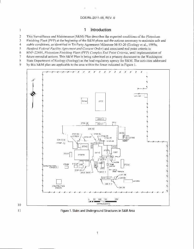
23 5.2.4 Airborne Emission Monitoring 24 Monitoring wi11 be performed via the near-facility ambient air monitoring network, which has an array of 25 monitoring stations near the PFP Complex and throughout the 200 West Area of the Hanford Site 26 (Figure 5). This system will act as indication of changes in emissions at the PFP Complex during Stage 2 27 S&M. The Hanford Site protocol established for emission monitoring includes provisions for data 28 co11ection, sampling frequencies , sample analysis, and data reporting (DOE/RL-91-50, Hanford Site 29 Environmental Monitoring Plan). Emissions will continue to be reported as part of the Hanford Site 30 annual reporting.
31 5.3 Waste Management
32 Wastes generated during slab removal and other post-transition actions during Stage 1 S&M will be 33 managed in accordance with Section 4.2, "Waste Management," and the associated ARARs of the RA WP 34 (DOE/RL-2011-03). Due to the fact that waste sites within the area covered by this S&M plan could be 35 assigned to different OUs, waste generated during Stage 2 S&M will be managed in accordance with the 36 CERCLA decision document covering the waste site generating the waste.
14

DOE/RL-2011 -59, REV. 0
.... - - --o
I
' I T-Plant "'"' g/0
I
..... ...., 0 t.. c..O
I I o'
O Near Facility Ambient 1',r Monitoring Station
t?Z:J Waste Site C, Facility
LJ Former 200 West Operational Area
0 0..25 D.5 0.75 1 km
0 0.25 O.S rrl I
. ~
·o ... I
200Tal. .......... 0
2
0 \ 0
l'-0
(> .... , S-Plant ..... % I o ~ g_,
_1 _,r Q__
Figure 5. Near-Facility Ambient Air Monitoring (TypicaO
3 5.4 Hazardous Material Management
ll200 0
4 Hazardous materials present during Stage I S&M will be managed in accordance with the RA WP.
CHS0¥'102<-0I
5 The amount of hazardous material remaining after transitioning to Stage 2 S&M should be minimal and 6 would consist of those materials described in WIDS site descriptions or be associated with surveillance, 7 maintenance, or site investigation activities . During Stage 2 S&M, these materials would be managed in 8 accordance with Hanford Site standard methods.
9 During both Stage 1 and Stage 2 S&M, applicable requirements for occupational safety, nuclear safety, IO and radiological safety will be implemented for control of potential personnel exposures to hazardous I 1 materials or conditions.
12 Work instructions will integrate occupational safety, nuclear safety, criticality safety, and radiological 13 safety, as applicable, to ensure worker protection.
14 5.5 Record Keeping and Documentation
15 Records generated from S&M activities are managed in accordance with Section 9.4 of the Tri-Party 16 Agreement Action Plan (Ecology et al., 1989b). The End Point Criteria document (HNF-22401) specifies 17 required documentation for turnover to S&M.
15
DOE/RL-2011-59, REV. 0
6 Radiological Controls
2 The radiological controls and protection program reduces the risks to personnel safety and/or health to 3 ALARA levels and ensures adequate protection of workers. The radiological protection program meets 4 the requirements of IO CFR 835 , "Occupational Radiation Protection."
5 Before S&M is performed, the proposed activity will be discussed with the radiological controls 6 organization to determine the scope and necessary radiological survey requirements. Technical 7 assessment documentation may be issued by the radiological controls organization to provide direction 8 concerning the isotopes of concern and any specific survey and/or air sampling requirements. Dependent 9 upon work scope and expected radiological conditions, an ALARA review may be perfonned as well.
10 Radiological control technicians (RCTs) will assess radiological conditions of the work/surveillance area 11 in accordance with standard practices and issued technical assessments, document survey results, and 12 ensure correct radiological postings/boundaries of the area.
13 Based upon the results of the radiological survey, a radiological work plan is issued describing the 14 appropriate personal protective clothing, dosimeter requirements, respiratory protection, and RCT 15 coverage requirements.
16 7 Emergency Management and Preparedness
17 The Emergency Management Program establishes a coordinated emergency response organization 18 capable of planning for, responding to, and recovering from industrial , security, and hazardous material 19 incidents. Emergency action plans identify the capabilities necessary to respond to emergency conditions, 20 provide guidance and instruction for initiating emergency response actions, and serve as a basis for 21 training personnel in emergency actions. An emergency response plan ( or Building Emergency Plan) may 22 continue to be in effect during slab removal but is likely to be discontinued as hazards are reduced and 23 work transitions into Stage 2 S&M. Emergency response actions within the emergency action plan are 24 provided for recognizing incidents and/or abnonnal conditions, initiating protective actions, and making 25 the proper notifications. The emergency action plans are consistent with Hanford Site emergency 26 processes and meet the requirements of state and federal regulations.
27 The potential hazards expected to be present during slab removal may warrant the staging of emergency 28 equipment in support of that activity. Subsequent to slab removal and other post-transition activities, the 29 S&M area of the PFP Complex will be unoccupied. Therefore, no permanent emergency equipment, 30 communication equipment, warning systems, personal protective equipment, or spill control and 31 containment supplies will be located within the fenced S&M area at the PFP Complex.
32 Prior to periodic entries during Stage 2 S&M, personnel will review appropriate procedures and attend 33 pre-job safety meetings. The procedures, emergency plans, and meetings dictate the appropriate 34 emergency equipment to be taken into the work areas and will identify PFP Complex specific hazards, 35 appropriate evacuation routes, and notifications to be made if an accident occurs.
36 8 Health and Safety
3 7 DOE self-implements the requirements of 29 CFR 1910.120, "Occupational Safety and Health 38 Standards," "Hazardous Waste Operations and Emergency Response," under the IO CFR 851 , " Worker 39 Safety and Health Program," regulatory program, which requires a fully developed health and safety 40 program. A health and safety plan (HASP), required under CERCLA, is developed when the decisions 41 and documents (e.g., RI/FS, RA WP, and other documents) are completed for the final disposition of the 42 facility in question. During Stage I S&M, the PFP HASP used during above-grade structure demolition
16

DOE/RL-2011-59, REV. 0
will continue to be used with modifications as necessary to reflect the nature and hazard of the activities 2 perfonned during that stage.
3 The safety and health program requirements for CERCLA work being perfonned on a hazardous waste 4 site are included in 29 CFR 1910.120. However, there is a note at the start of Section b of the standard:
5 "NOTE TO (b) : Safety and health programs developed and implemented to meet other 6 f ederal, state, or local regulations are considered acceptable in meeting this requirement 7 if they cover or are modified to cover the topics required in this paragraph. An additional 8 or separate safety and health program is not required by this paragraph."
9 During Stage 2 S&M, DOE may elect to continue to have a HASP to cover the Stage 2 activities or may IO decide to use this provision to perfonn work under the overall safety and health program. The latter 11 approach is more commonly used for long-term S&M activities with less significant hazards.
12 9 Institutional Controls
13 Institutional controls (ICs) are nonengineered instruments, such as administrative and legal controls, that 14 help minimize the potential for human exposure to contamination and/or protect the integrity of the remedy. 15 The current controlling CERCLA document is an interim removal action. Decisions for I Cs will be 16 documented within the final CERCLA remedial action decision document for the PFP Complex, as needed. 17 Until a final remedy is in place for the PFP Complex, existing access and other controls may be used to 18 minimize human exposure and to contain contaminants.
19 10 Safeguards and Security
20 Subsequent to transition to Stage 2 S&M, the area of the PFP Complex inside the fence (Figure 1) will 21 not be occupied except at those times when periodic S&M activities are occurring. There will be no 22 intrusion alanns or routine security patrols within the perimeter fence of the PFP Complex. Hanford 23 Patrol will provide routine security patrols throughout the 200 West Area, including checks of the 24 PFP Complex area. o specific safeguards and security requirements have been identified for the PFP 25 Complex area during Stage 2 S&M.
26 Access to the Hanford Site is controlled by checkpoints on authorized vehicle access roads . All personnel 27 entering the Hanford Site must display a DOE-issued identification badge. Personnel on the Hanford Site 28 are also subject to random searches. A single fence will remain around portions the PFP Complex with 29 locked access gates controlled by the S&M organization .
30 11 Schedule
31 Pre-transition portions of the removal action are scheduled to be completed by September 30, 2016, per 32 Tri-Party Agreement Milestone M-083-00A (Ecology et al. , 1989a). Transition to Stage 1 S&M will 33 occur upon achievement of a safe and stable condition and completion of other actions required by 34 Milestone M-083-00A. Select removal actions will continue during Stage 1 S&M with completion of 35 removal of the 236-Z and 242-Z slabs and post-transition End Point Criteria document (HNF-2240 I) 36 activities by September 30, 2017, in accordance with the RA WP (DOE/RL-2011-03). The annual S&M 37 surveillance and preventive maintenance will be implemented in appropriate work packages.
38 12 References
39 10 CFR 835, "Occupational Radiation Protection," Code of Federal Regulations. Available at: 40 http://www.gpo.gov/fdsys/pkg/CFR-201O-title10-vo14/xml/CFR-2010-titlel 0-vol4-part835.xml.
17
DOE/RL-2011-59, REV. 0
10 CFR 851, "Worker Safety and Health Program," Code of Federal Regulations. Available at: 2 http: //www.gpo.gov/fdsys/pkg/CFR-2010-title 1O-vo14/xml/CFR-2010-titlel 0-vo14-part851.xml.
3 29 CFR 1910.120, "Occupational Safety and Health Standards," " Hazardous Waste Operations and 4 Emergency Response," Code of Federal Regulations. Available at: 5 http://www.gpo.gov/fdsys/pkg/CFR-201 0-title29-vo16/xml/CFR-20 I 0-title29-vol6-part 191 0.xml.
6 Comprehensive Environmental Response, Compensation, and Liability Act of 1980, 42 USC 9601 , et seq. , 7 Pub. L. I 07-377, December 31, 2002. Available at: http: //epw.senate.gov/cerc1a.pd£
8 DOE G 430.1-2, 1999, implementation Guide for Surveillance and Maintenance during Facility 9 Transition and Disposition, U.S. Department of Energy, Washington, D.C. Available at:
IO https://www.directives.doe.gov/directives-documents/400-series/0430. l -EGuide-2.
11 DOE/RL-91-50, 20 I 5, Hanford Site Environmental Monitoring Plan, Rev. 6A, U.S. Department of 12 Energy, Richland Operations Office, Richland, Washington. Available at: I 3 http://pdw.hanford.gov/arpir/index.cfm/viewDoc?accession= I 503160460.
14 DOE/RL-96-82, 2004, Hanford Facility Dangerous Waste Closure Plan, 241-Z Treatment and Storage 15 Tanks, Rev. I , U.S. Department of Energy, Richland Operations Office, Richland, 16 Washington. Available at: http://pdw.hanford.gov/arpir/pdf.cfm?accession=D44932 l 9.
17 DOE/RL-2004-05, 2004, Engineering Evaluation/Cost Analysis for the Plutonium Finishing Plant 18 Above-Grade Structures , Rev. 1 Reissue, U.S. Department of Energy, Richland Operations 19 Office, Richland, Washington . Availab le at: 20 http://pdw.hanford.gov/arpir/index.cfm/viewDoc?accession=D63097 l 0.
21 DOE/RL-2005-13 , 2005 , Action Memorandum for the Plutonium Finishing Plant Above-Grade 22 Structures Non-Time Critical Removal Action, Rev. 0, U.S. Department of Energy, Richland 23 Operations Office, Richland, Washington. Available at: 24 http://pdw.hanford.gov/arpir/index.cfm/viewDoc?accession=DA009 I 4134.
25 DOE/RL-2011-03 , 2014, Removal Action Work Plan for the Deactivation, Decontamination, 26 Decommissioning, and Demolition o,f the Plutonium Finishing Plant Complex, Rev. 0, 27 U.S . Department of Energy, Richland Operations Office, Richland, Washington . Availab le at: 28 http: //pdw.hanford.gov/arpir/index.cfm/viewDoc?accession=0084836. 29 30 Modified by:
31 TPA-CN-681, 2015, Tri-Party Agreement Change Notice Form: DOEIRL-2011-03, Removal 32 Action Work Plan for the Deactivation, Decontamination, Decommissioning, and Demolition 33 of the Plutonium Finishing Plant Complex, Rev 0, dated November 5, U.S. Department of 34 Energy, Richland Operations Office, U.S. Environmental Protection Agency, and Washington 35 State Department of Ecology, Richland, Washington. Available at: 36 http: //pdw.hanford.gov/arpir/index.cfm/viewDoc?accession=0079500H.
37 TPA-CN-682, 2015 , Tri-Party Agreement Change Notice Form: NMS-16404, Plutonium 38 Finishing Plant (PFP) Complex Endpoint Criteria, Rev. 0, dated November 5, 39 U.S. Department of Energy, Richland Operations Office, U.S . Environmental Protection 40 Agency, and Washington State Department of Ecology, Richland, Washington. Available at : 41 http://pdw.hanford.gov/arpir/index.cfm/viewDoc?accession=0079499H
42
18

DOE/RL-2011 -59, REV. 0
1 Ecology, EPA, and DOE, 1989a, Hanford Federal Facility Agreement and Consent Order, 2 vols., 2 as amended, Washington State Department of Ecology, U.S. Enviromnental Protection 3 Agency, and U.S. Department of Energy, Olympia, Washington. Available at: 4 http://www.hanford.gov/?page=8 l .
5 Ecology, EPA, and DOE, 1989b, Hariford Federal Facility Agreement and Consent Order Action Plan, 6 as amended, Washington State Department of Ecology, U.S. Enviromnental Protection 7 Agency, and U.S. Department of Energy, Olympia, Washington. Available at: 8 http://www.hanford.gov/?page=82.
9 EPA, Ecology, and DOE, 2011 , Record of Decision Hariford 200 Area Superfund Site 200-CW-5 and 10 200-PW-I, 200-PW-3, and 200-PW-6 Operable Units , U.S. Environmental Protection 11 Agency, Washington State Department of Ecology, and U.S. Department of Energy, Olympia, 12 Washington. Available at: 13 http://pdw.hanford.gov/arpir/index.cfm/view Doc?accession=0093644.
14 H-2-29620, 2010, Structural Concrete Foundation Plan & Details, Rev. 6, CH2M HILL Plateau 15 Remediation Company, Richland, Washington.
16 HNF-22401, 2004, Plutonium Finishing Plant (PFP) Complex End Point Criteria, Rev. 0, Fluor Hanford, 17 Inc., Richland, Washington. Available at : 18 http://pdw.hanford.gov/arpir/index.cfm/viewDoc?accession=D6455017. 19 20 Modified by:
21 TPA-CN-682, 2015 , Tri-Party Agreement Change Notice Form: NMS-16404, Plutonium 22 Finishing Plant (PFP) Complex Endpoint Criteria, Rev O [also identified as HNF-22401 , 23 Rev OJ , dated November 5, U.S. Department of Energy, Richland Operations Office, 24 U.S. Enviromnental Protection Agency, and Washington State Department of Ecology, 25 Richland, Washington. Available at: 26 http://pdw.hanford.gov/arpir/index.cfm/viewDoc?accession=0079499H.
27 HNF-33999, 2007, 241-Z As Le.ft Characterization , Rev. 0, Fluor Hanford, Inc., Richland, Washington .
28 M-083 -00A, 2002, Hanford Federal Facility Agreement and Consent Order (Tri-Party Agreement): 29 Proposed Tri-Party Agreement Modifications and Reference Documents for Plutonium 30 Finishing Plant Transition and Selected Disposition Milestones (M-83-00A) , U.S. Department 31 of Energy, Richland Operations Office, U.S . Enviromnental Protection Agency, and 32 Washington State Department of Ecology, Richland, Washington, January 30. Available at: 33 http://pdw.hanford.gov/arpir/index.cfin/viewDoc?accession=D9084946.
34 Resource Conservation and Recovery Act of 1976, 42 USC 6901, et seq. Available at: 35 http://www.epa.gov/regulations/laws/rcra.html.
36
19

DOE/RL-2011-59, REV. 0
2 This page intentionally left blank.
20