Embed Size (px)
Citation preview
Survey on Wireless and Mobile ATM Networks
Tamer Nadeem [email protected]
Raymond Miller [email protected]
Wireless & Mobile ATM Networks
2
Table of Contents:
1 Introduction............................................................................... 3
2 Wireless ATM System Architecture: ...................................... 4 2.1 Service requirements: ..........................................................................4
2.2 Wireless ATM System Model .............................................................5
2.3 Wireless ATM Protocol Architecture..................................................6
3 Wireless ATM Design Issues ................................................... 7 3.1 Radio Access Layer protocols.............................................................7
3.1.1 Radio Physical Layer (PHY) .......................................................................... 7
3.1.2 Medium Access Control (MAC)..................................................................... 8
3.1.3 Data Link Control (DLC).............................................................................. 11
3.1.4 Wireless Control ........................................................................................... 12
3.2 Mobile ATM Protocol Extension......................................................13 3.2.1 Location Management .................................................................................. 13
3.2.1.1 Integrated Scheme.............................................................................................................13
Assigning addresses to MTs: .................................................................................................13
Connection setup: ..................................................................................................................14
Location Update: ...................................................................................................................15
3.2.1.2 Location Management as an External Service...................................................................16
3.2.1.3 PNNI Location Management schemes..............................................................................16
Mobile PNNI Scheme............................................................................................................17
Location Registers (LR) Scheme...........................................................................................18
3.2.2 Handoff (Handover) Control......................................................................... 19
3.2.2.1 Full Re-establishment scheme:..........................................................................................20
3.2.2.2 Path Extension scheme:.....................................................................................................20
3.2.2.3 Partial Path Re-routing (Incremental Re-establish) scheme: .............................................21
Basic Concepts: .....................................................................................................................21
Crossover Switch discovery:..................................................................................................25
Cell Synchronization: ............................................................................................................27
3.2.2.4 Handoff in Multicast Connection: .....................................................................................30
3.2.2.5 Other Handoff schemes: ....................................................................................................31
4 Conclusion and Future Work ................................................33
5 References................................................................................35
Wireless & Mobile ATM Networks
3
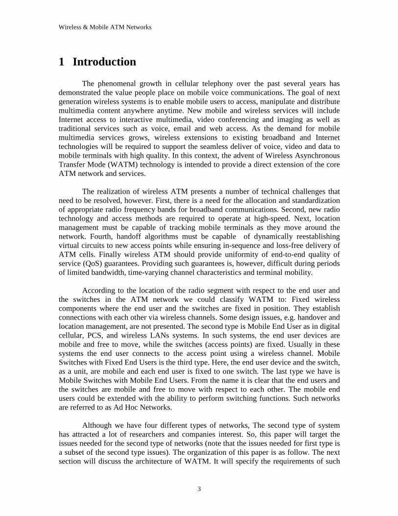
1 Introduction The phenomenal growth in cellular telephony over the past several years has
demonstrated the value people place on mobile voice communications. The goal of next generation wireless systems is to enable mobile users to access, manipulate and distribute multimedia content anywhere anytime. New mobile and wireless services will include Internet access to interactive multimedia, video conferencing and imaging as well as traditional services such as voice, email and web access. As the demand for mobile multimedia services grows, wireless extensions to existing broadband and Internet technologies will be required to support the seamless deliver of voice, video and data to mobile terminals with high quality. In this context, the advent of Wireless Asynchronous Transfer Mode (WATM) technology is intended to provide a direct extension of the core ATM network and services.
The realization of wireless ATM presents a number of technical challenges that
need to be resolved, however. First, there is a need for the allocation and standardization of appropriate radio frequency bands for broadband communications. Second, new radio technology and access methods are required to operate at high-speed. Next, location management must be capable of tracking mobile terminals as they move around the network. Fourth, handoff algorithms must be capable of dynamically reestablishing virtual circuits to new access points while ensuring in-sequence and loss-free delivery of ATM cells. Finally wireless ATM should provide uniformity of end-to-end quality of service (QoS) guarantees. Providing such guarantees is, however, difficult during periods of limited bandwidth, time-varying channel characteristics and terminal mobility.
According to the location of the radio segment with respect to the end user and
the switches in the ATM network we could classify WATM to: Fixed wireless components where the end user and the switches are fixed in position. They establish connections with each other via wireless channels. Some design issues, e.g. handover and location management, are not presented. The second type is Mobile End User as in digital cellular, PCS, and wireless LANs systems. In such systems, the end user devices are mobile and free to move, while the switches (access points) are fixed. Usually in these systems the end user connects to the access point using a wireless channel. Mobile Switches with Fixed End Users is the third type. Here, the end user device and the switch, as a unit, are mobile and each end user is fixed to one switch. The last type we have is Mobile Switches with Mobile End Users. From the name it is clear that the end users and the switches are mobile and free to move with respect to each other. The mobile end users could be extended with the ability to perform switching functions. Such networks are referred to as Ad Hoc Networks.
Although we have four different types of networks, The second type of system
has attracted a lot of researchers and companies interest. So, this paper will target the issues needed for the second type of networks (note that the issues needed for first type is a subset of the second type issues). The organization of this paper is as follow. The next section will discuss the architecture of WATM. It will specify the requirements of such
Wireless & Mobile ATM Networks
4
systems and the models that are used in the current systems. The next section will be dedicated to the design issues in wireless ATM systems. The two main layers needed for the WATM and their sublayers will be discussed here. The discussion of the radio access layer will include the requirements for the physical connection between the mobile users and the access points, the WATM MAC protocols, data link control issues, and the wireless control. The second layer (mobility support layer) will discuss the schemes for location management and handoff control. The QoS issues of WATM are beyond the scope of this paper. The conclusion presents trends and future issues for WATM.
2 Wireless ATM System Architecture:
2.1 Service requirements: The general aim of designing a wireless ATM [1,2] is to provide an integrated
services wireless network that provides extensions of wired ATM network capabilities in a relatively transparent, seamless and efficient manner. This means that the WATM system should support a reasonable range of service classes, bit-rates and quality-of-service (QoS) levels associated with ATM. Of course, it is recognized that there may be a quantitative difference in achievable service characteristics due to fundamental limitations of the radio medium such as: limits on bit-rate, delay, cell-loss, etc., but these can perhaps be kept to a minimum via innovative technical approaches.
WATM must support many services such as text e-mail, client-server data, digital
audio and video/multimedia applications in addition to conventional telephony. These services span a fairly broad range of bit-rate, service class and quality-of-service requirements. As in the B_ISDN’s integrated framework, services may either be connection-oriented (CO) or connectionless (CL). Connection-oriented services include constant bit-rate (CBR) with selectable fixed bandwidth, and variable bit-rate (VBR) with statistically multiplexed bandwidth allocation. Connectionless services include “best effort” or “available bit-rate (ABR)” packet data (similar to that provided by current packet switching networks) as well as high-throughput burst data service for file transfer, etc.
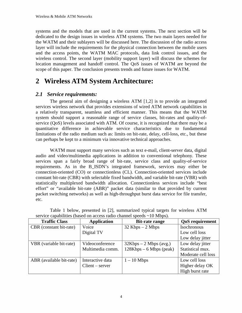
Table 1 below, presented in [2], summarized typical targets for wireless ATM
service capabilities (based on access radio channel speeds ~10 Mbps). Traffic Class Application Bit-rate range QoS requirement
CBR (constant bit-rate) Voice Digital TV
32 Kbps – 2 Mbps Isochronous Low cell loss Low delay jitter
VBR (variable bit-rate) Videoconference Multimedia comm.
32Kbps – 2 Mbps (avg.) 128Kbps – 6 Mbps (peak)
Low delay jitter Statistical mux. Moderate cell loss
ABR (available bit-rate) Interactive data Client – server
1 – 10 Mbps Low cell loss Higher delay OK High burst rate
Wireless & Mobile ATM Networks
5
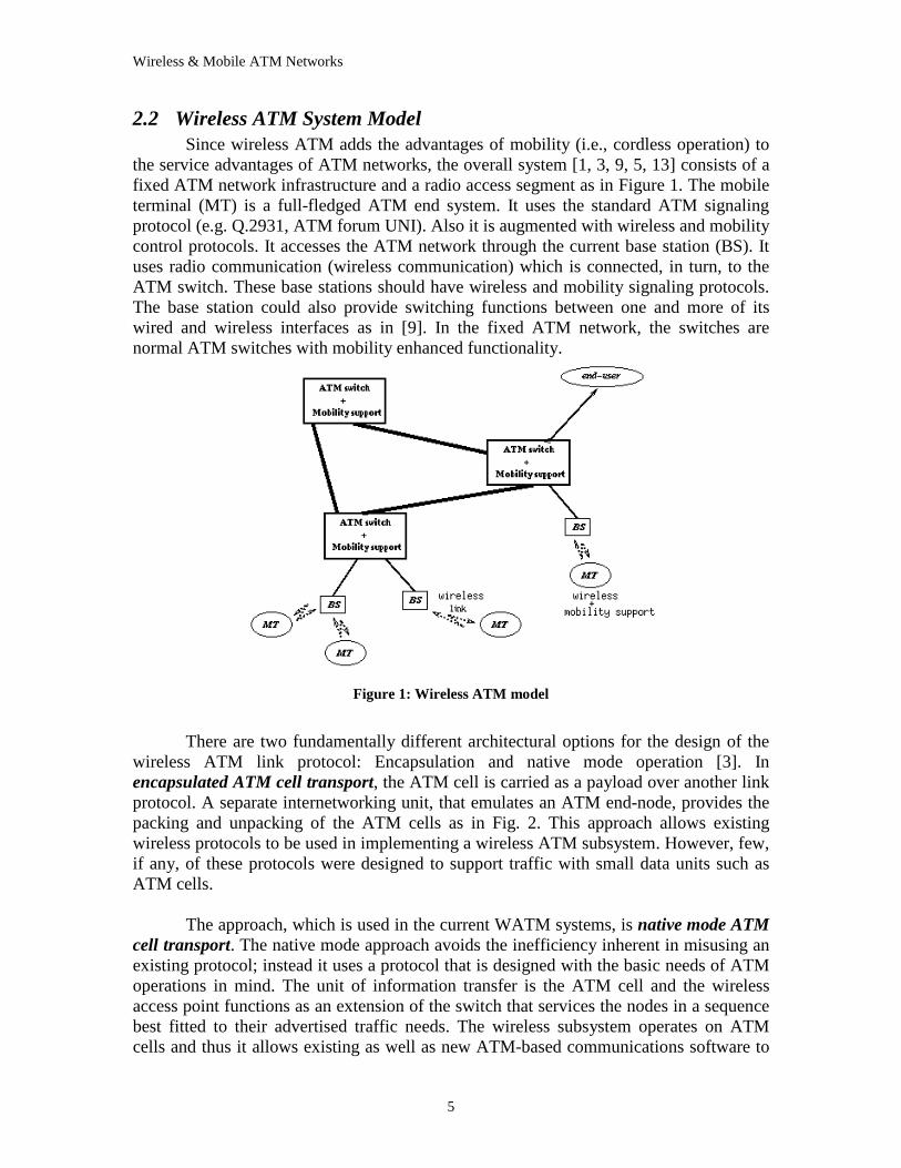
2.2 Wireless ATM System Model Since wireless ATM adds the advantages of mobility (i.e., cordless operation) to
the service advantages of ATM networks, the overall system [1, 3, 9, 5, 13] consists of a fixed ATM network infrastructure and a radio access segment as in Figure 1. The mobile terminal (MT) is a full-fledged ATM end system. It uses the standard ATM signaling protocol (e.g. Q.2931, ATM forum UNI). Also it is augmented with wireless and mobility control protocols. It accesses the ATM network through the current base station (BS). It uses radio communication (wireless communication) which is connected, in turn, to the ATM switch. These base stations should have wireless and mobility signaling protocols. The base station could also provide switching functions between one and more of its wired and wireless interfaces as in [9]. In the fixed ATM network, the switches are normal ATM switches with mobility enhanced functionality.
Figure 1: Wireless ATM model
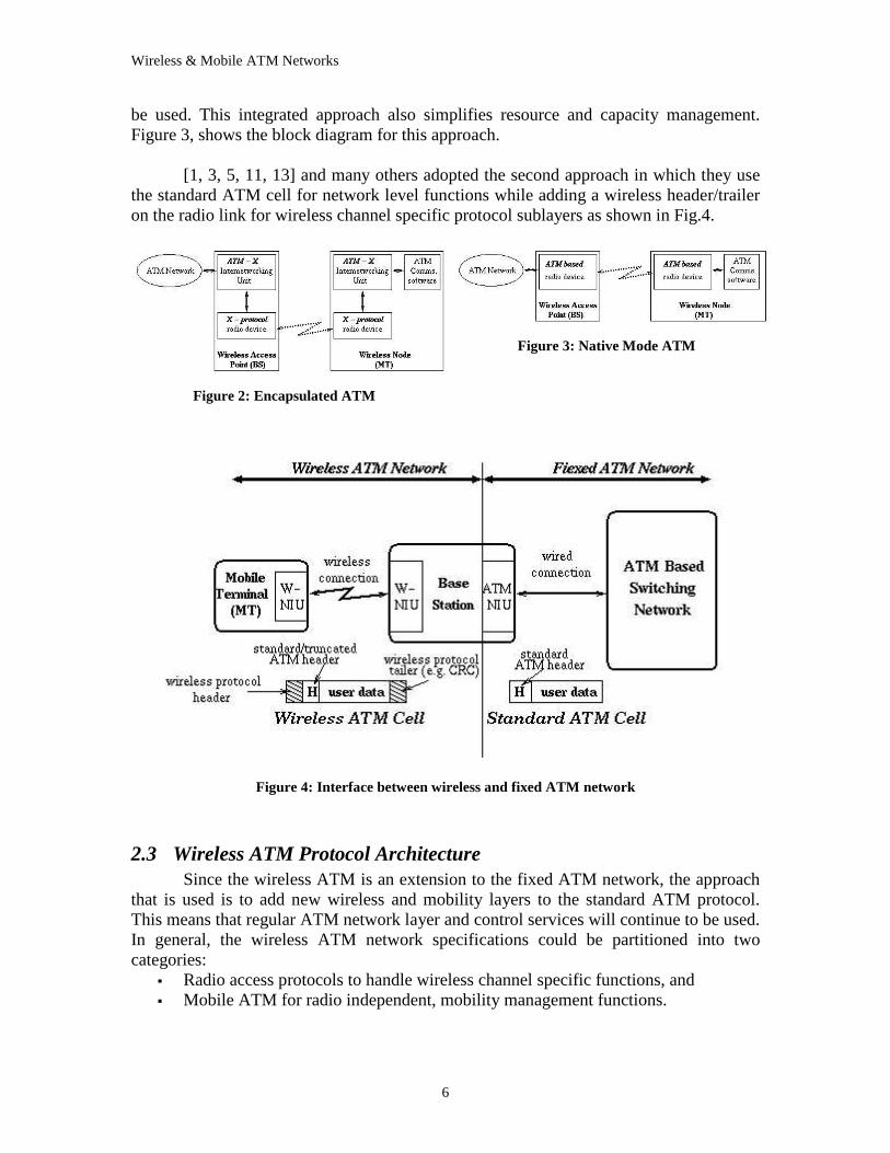
There are two fundamentally different architectural options for the design of the
wireless ATM link protocol: Encapsulation and native mode operation [3]. In encapsulated ATM cell transport, the ATM cell is carried as a payload over another link protocol. A separate internetworking unit, that emulates an ATM end-node, provides the packing and unpacking of the ATM cells as in Fig. 2. This approach allows existing wireless protocols to be used in implementing a wireless ATM subsystem. However, few, if any, of these protocols were designed to support traffic with small data units such as ATM cells.
The approach, which is used in the current WATM systems, is native mode ATM
cell transport. The native mode approach avoids the inefficiency inherent in misusing an existing protocol; instead it uses a protocol that is designed with the basic needs of ATM operations in mind. The unit of information transfer is the ATM cell and the wireless access point functions as an extension of the switch that services the nodes in a sequence best fitted to their advertised traffic needs. The wireless subsystem operates on ATM cells and thus it allows existing as well as new ATM-based communications software to
Wireless & Mobile ATM Networks
6
be used. This integrated approach also simplifies resource and capacity management. Figure 3, shows the block diagram for this approach.
[1, 3, 5, 11, 13] and many others adopted the second approach in which they use
the standard ATM cell for network level functions while adding a wireless header/trailer on the radio link for wireless channel specific protocol sublayers as shown in Fig.4.
Figure 2: Encapsulated ATM
Figure 3: Native M ode ATM
Figure 4: Inter face between wireless and fixed ATM network
2.3 Wireless ATM Protocol Architecture Since the wireless ATM is an extension to the fixed ATM network, the approach
that is used is to add new wireless and mobility layers to the standard ATM protocol. This means that regular ATM network layer and control services will continue to be used. In general, the wireless ATM network specifications could be partitioned into two categories:
�� Radio access protocols to handle wireless channel specific functions, and �� Mobile ATM for radio independent, mobility management functions.
Wireless & Mobile ATM Networks
7
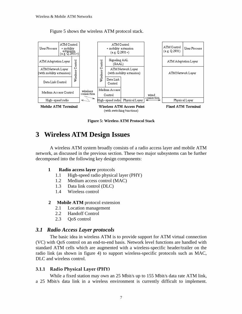
Figure 5 shows the wireless ATM protocol stack.
Figure 5: Wireless ATM Protocol Stack
3 Wireless ATM Design Issues
A wireless ATM system broadly consists of a radio access layer and mobile ATM network, as discussed in the previous section. These two major subsystems can be further decomposed into the following key design components:
1 Radio access layer protocols
1.1 High-speed radio physical layer (PHY) 1.2 Medium access control (MAC) 1.3 Data link control (DLC) 1.4 Wireless control
2 Mobile ATM protocol extension
2.1 Location management 2.2 Handoff Control 2.3 QoS control
3.1 Radio Access Layer protocols The basic idea in wireless ATM is to provide support for ATM virtual connection
(VC) with QoS control on an end-to-end basis. Network level functions are handled with standard ATM cells which are augmented with a wireless-specific header/trailer on the radio link (as shown in figure 4) to support wireless-specific protocols such as MAC, DLC and wireless control.
3.1.1 Radio Physical Layer (PHY) While a fixed station may own an 25 Mbit/s up to 155 Mbit/s data rate ATM link,
a 25 Mbit/s data link in a wireless environment is currently difficult to implement.
Wireless & Mobile ATM Networks
8
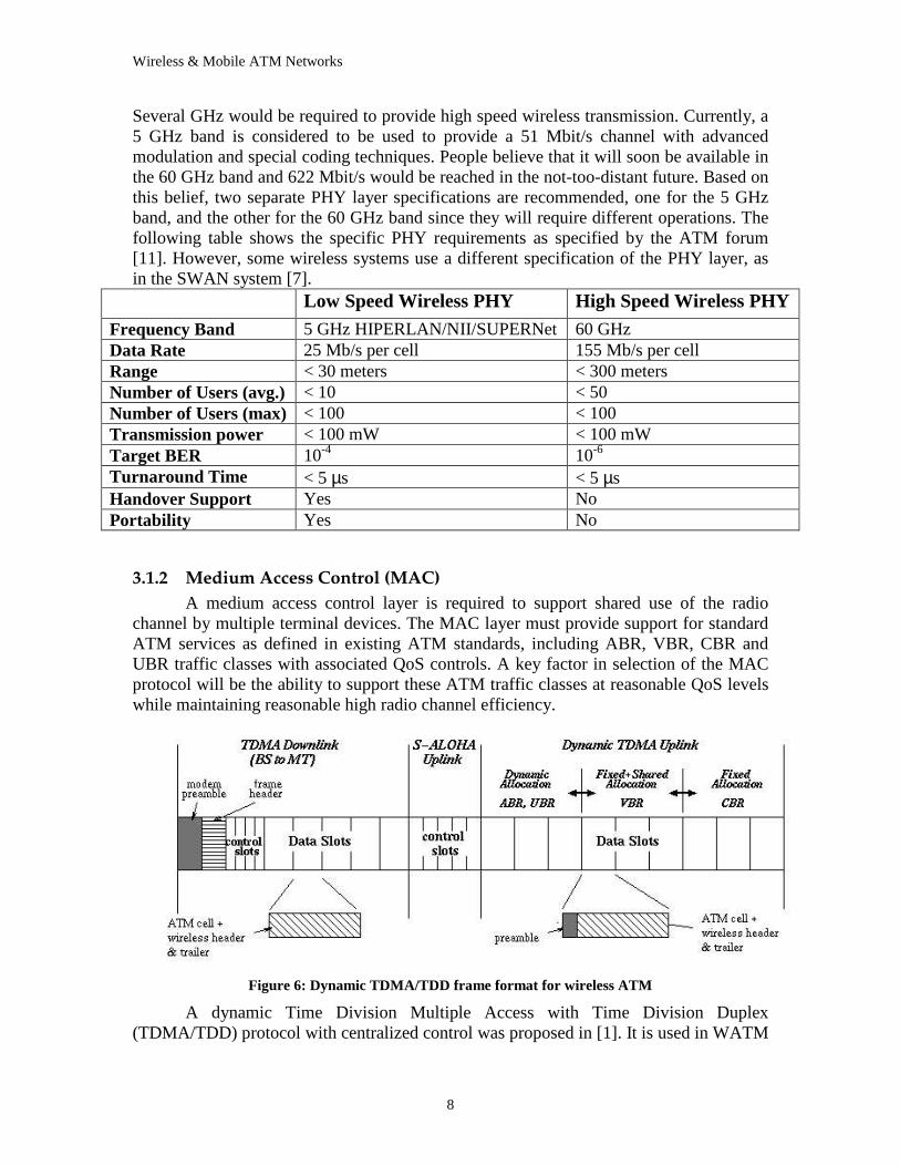
Several GHz would be required to provide high speed wireless transmission. Currently, a 5 GHz band is considered to be used to provide a 51 Mbit/s channel with advanced modulation and special coding techniques. People believe that it will soon be available in the 60 GHz band and 622 Mbit/s would be reached in the not-too-distant future. Based on this belief, two separate PHY layer specifications are recommended, one for the 5 GHz band, and the other for the 60 GHz band since they will require different operations. The following table shows the specific PHY requirements as specified by the ATM forum [11]. However, some wireless systems use a different specification of the PHY layer, as in the SWAN system [7].
Low Speed Wireless PHY High Speed Wireless PHY
Frequency Band 5 GHz HIPERLAN/NII/SUPERNet 60 GHz Data Rate 25 Mb/s per cell 155 Mb/s per cell Range < 30 meters < 300 meters Number of Users (avg.) < 10 < 50 Number of Users (max) < 100 < 100 Transmission power < 100 mW < 100 mW Target BER 10-4 10-6 Turnaround Time < 5 µs < 5 µs Handover Support Yes No Por tability Yes No
3.1.2 Medium Access Control (MAC) A medium access control layer is required to support shared use of the radio
channel by multiple terminal devices. The MAC layer must provide support for standard ATM services as defined in existing ATM standards, including ABR, VBR, CBR and UBR traffic classes with associated QoS controls. A key factor in selection of the MAC protocol will be the ability to support these ATM traffic classes at reasonable QoS levels while maintaining reasonable high radio channel efficiency.
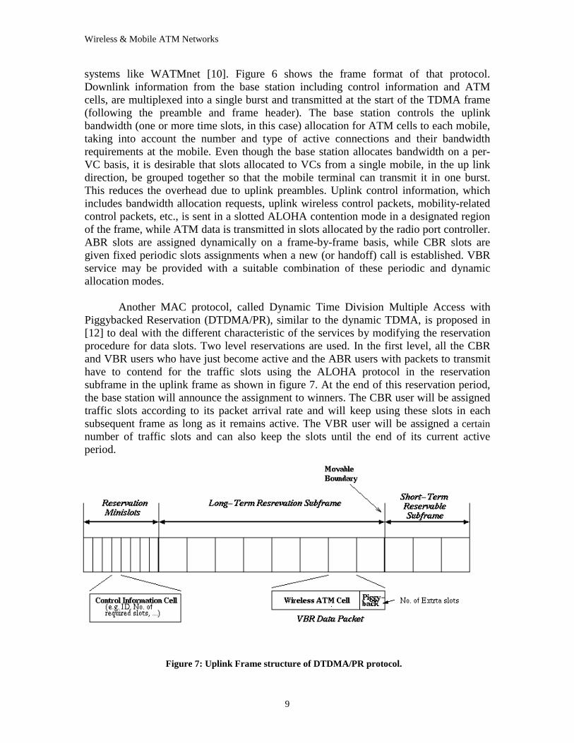
Figure 6: Dynamic TDM A/TDD frame format for wireless ATM
A dynamic Time Division Multiple Access with Time Division Duplex (TDMA/TDD) protocol with centralized control was proposed in [1]. It is used in WATM
Wireless & Mobile ATM Networks
9
systems like WATMnet [10]. Figure 6 shows the frame format of that protocol. Downlink information from the base station including control information and ATM cells, are multiplexed into a single burst and transmitted at the start of the TDMA frame (following the preamble and frame header). The base station controls the uplink bandwidth (one or more time slots, in this case) allocation for ATM cells to each mobile, taking into account the number and type of active connections and their bandwidth requirements at the mobile. Even though the base station allocates bandwidth on a per-VC basis, it is desirable that slots allocated to VCs from a single mobile, in the up link direction, be grouped together so that the mobile terminal can transmit it in one burst. This reduces the overhead due to uplink preambles. Uplink control information, which includes bandwidth allocation requests, uplink wireless control packets, mobility-related control packets, etc., is sent in a slotted ALOHA contention mode in a designated region of the frame, while ATM data is transmitted in slots allocated by the radio port controller. ABR slots are assigned dynamically on a frame-by-frame basis, while CBR slots are given fixed periodic slots assignments when a new (or handoff) call is established. VBR service may be provided with a suitable combination of these periodic and dynamic allocation modes.
Another MAC protocol, called Dynamic Time Division Multiple Access with
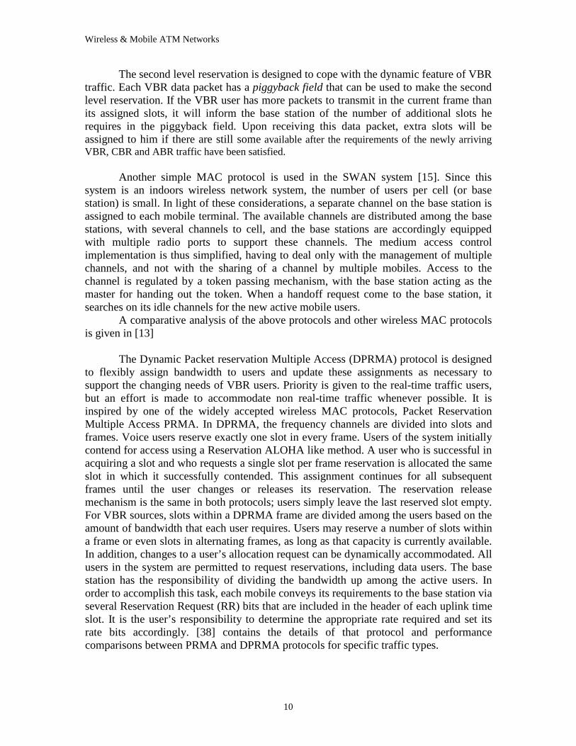
Piggybacked Reservation (DTDMA/PR), similar to the dynamic TDMA, is proposed in [12] to deal with the different characteristic of the services by modifying the reservation procedure for data slots. Two level reservations are used. In the first level, all the CBR and VBR users who have just become active and the ABR users with packets to transmit have to contend for the traffic slots using the ALOHA protocol in the reservation subframe in the uplink frame as shown in figure 7. At the end of this reservation period, the base station will announce the assignment to winners. The CBR user will be assigned traffic slots according to its packet arrival rate and will keep using these slots in each subsequent frame as long as it remains active. The VBR user will be assigned a certain number of traffic slots and can also keep the slots until the end of its current active period.
Figure 7: Uplink Frame structure of DTDM A/PR protocol.
Wireless & Mobile ATM Networks
10
The second level reservation is designed to cope with the dynamic feature of VBR traffic. Each VBR data packet has a piggyback field that can be used to make the second level reservation. If the VBR user has more packets to transmit in the current frame than its assigned slots, it will inform the base station of the number of additional slots he requires in the piggyback field. Upon receiving this data packet, extra slots will be assigned to him if there are still some available after the requirements of the newly arriving VBR, CBR and ABR traffic have been satisfied.
Another simple MAC protocol is used in the SWAN system [15]. Since this
system is an indoors wireless network system, the number of users per cell (or base station) is small. In light of these considerations, a separate channel on the base station is assigned to each mobile terminal. The available channels are distributed among the base stations, with several channels to cell, and the base stations are accordingly equipped with multiple radio ports to support these channels. The medium access control implementation is thus simplified, having to deal only with the management of multiple channels, and not with the sharing of a channel by multiple mobiles. Access to the channel is regulated by a token passing mechanism, with the base station acting as the master for handing out the token. When a handoff request come to the base station, it searches on its idle channels for the new active mobile users.
A comparative analysis of the above protocols and other wireless MAC protocols is given in [13]
The Dynamic Packet reservation Multiple Access (DPRMA) protocol is designed
to flexibly assign bandwidth to users and update these assignments as necessary to support the changing needs of VBR users. Priority is given to the real-time traffic users, but an effort is made to accommodate non real-time traffic whenever possible. It is inspired by one of the widely accepted wireless MAC protocols, Packet Reservation Multiple Access PRMA. In DPRMA, the frequency channels are divided into slots and frames. Voice users reserve exactly one slot in every frame. Users of the system initially contend for access using a Reservation ALOHA like method. A user who is successful in acquiring a slot and who requests a single slot per frame reservation is allocated the same slot in which it successfully contended. This assignment continues for all subsequent frames until the user changes or releases its reservation. The reservation release mechanism is the same in both protocols; users simply leave the last reserved slot empty. For VBR sources, slots within a DPRMA frame are divided among the users based on the amount of bandwidth that each user requires. Users may reserve a number of slots within a frame or even slots in alternating frames, as long as that capacity is currently available. In addition, changes to a user’s allocation request can be dynamically accommodated. All users in the system are permitted to request reservations, including data users. The base station has the responsibility of dividing the bandwidth up among the active users. In order to accomplish this task, each mobile conveys its requirements to the base station via several Reservation Request (RR) bits that are included in the header of each uplink time slot. It is the user’s responsibility to determine the appropriate rate required and set its rate bits accordingly. [38] contains the details of that protocol and performance comparisons between PRMA and DPRMA protocols for specific traffic types.
Wireless & Mobile ATM Networks
11
3.1.3 Data Link Control (DLC) A data link control layer is necessary to mitigate the effect of radio channel errors
before cells are released to the ATM network Layer. Since end-to-end ATM performance is sensitive to cell loss, powerful error control procedures are a requirement for the WATM radio access segment. Available options include error detection/retransmission protocols and forward error correction methods. A unique consideration for wireless ATM is the requirement for relatively low delay jitter for QoS-based service such as VBR and CBR, indicating a possible need for new time-constrained retransmission control procedures.
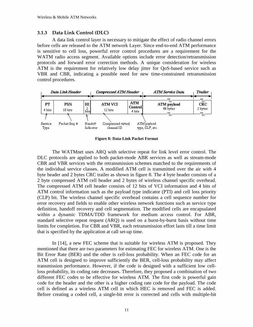
Figure 8: Data-L ink Packet Format
The WATMnet uses ARQ with selective repeat for link level error control. The
DLC protocols are applied to both packet-mode ABR services as well as stream-mode CBR and VBR services with the retransmission schemes matched to the requirements of the individual service classes. A modified ATM cell is transmitted over the air with 4 byte header and 2 bytes CRC trailer as shown in figure 8. The 4 byte header consists of a 2 byte compressed ATM cell header and 2 bytes of wireless channel specific overhead. The compressed ATM cell header consists of 12 bits of VCI information and 4 bits of ATM control information such as the payload type indicator (PTI) and cell loss priority (CLP) bit. The wireless channel specific overhead contains a cell sequence number for error recovery and fields to enable other wireless network functions such as service type definition, handoff recovery and cell segmentation. The modified cells are encapsulated within a dynamic TDMA/TDD framework for medium access control. For ABR, standard selective repeat request (ARQ) is used on a burst-by-burst basis without time limits for completion. For CBR and VBR, each retransmission effort lasts till a time limit that is specified by the application at call set-up time.
In [14], a new FEC scheme that is suitable for wireless ATM is proposed. They
mentioned that there are two parameters for estimating FEC for wireless ATM. One is the Bit Error Rate (BER) and the other is cell-loss probability. When an FEC code for an ATM cell is designed to improve sufficiently the BER, cell-loss probability may affect transmission performance. However, if the code is designed with a sufficient low cell-loss probability, its coding rate decreases. Therefore, they proposed a combination of two different FEC codes to be effective for wireless ATM. The first code is powerful gain code for the header and the other is a higher coding rate code for the payload. The code cell is defined as a wireless ATM cell in which HEC is removed and FEC is added. Before creating a coded cell, a single-bit error is corrected and cells with multiple-bit
Wireless & Mobile ATM Networks
12
errors are discarded. After this, HEC is removed. When errors after the header FEC are detected, the cells are discarded in the radio section. After the wireless section, a new HEC is generated for a wired section.
The SWAN network uses FEC and selective retransmission optionally specified
on a per-VC basis at connection set-up, for link level error control. Synchronous Data Link Control (SDLC) frames are sent over the air with each SDLC frame containing one or more link cells. Link cells are either of type ATMLC defined to carry an encapsulated ATM cell or of type MACSIGLC for MAC-level signaling. All link cells are composed of a fixed 6-byte header, and a body whose contents depend on the type of link cell. The fixed 6 byte header consists of 3 bytes of radio port-id and MAC protocol information and a 3 byte FEC field uses an (8,4) linear code to forward error correct the preceding 3 bytes. The body of the ATMLC contains an encapsulated ATM cell together with link-level error control information (a 2-byte CRC code for VCs using link level retransmission).
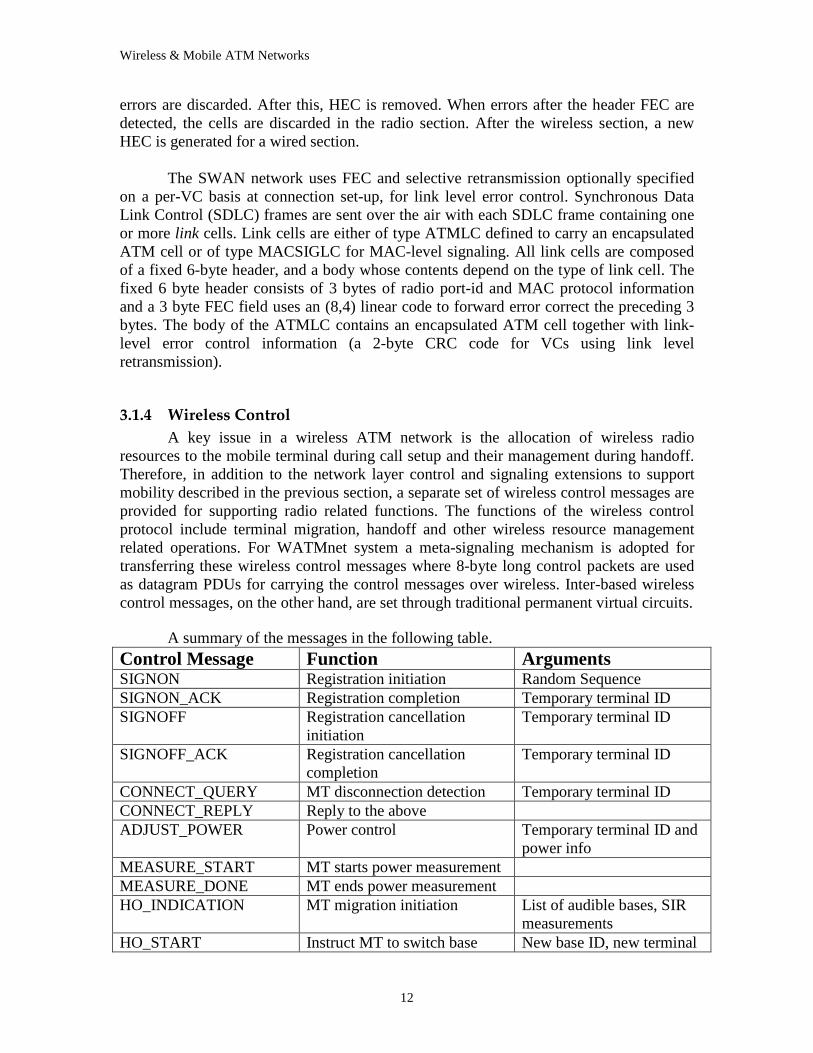
3.1.4 Wireless Control A key issue in a wireless ATM network is the allocation of wireless radio
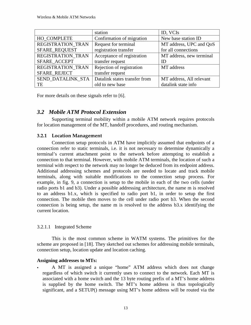
resources to the mobile terminal during call setup and their management during handoff. Therefore, in addition to the network layer control and signaling extensions to support mobility described in the previous section, a separate set of wireless control messages are provided for supporting radio related functions. The functions of the wireless control protocol include terminal migration, handoff and other wireless resource management related operations. For WATMnet system a meta-signaling mechanism is adopted for transferring these wireless control messages where 8-byte long control packets are used as datagram PDUs for carrying the control messages over wireless. Inter-based wireless control messages, on the other hand, are set through traditional permanent virtual circuits.
A summary of the messages in the following table.
Control Message Function Arguments SIGNON Registration initiation Random Sequence SIGNON_ACK Registration completion Temporary terminal ID SIGNOFF Registration cancellation
initiation Temporary terminal ID
SIGNOFF_ACK Registration cancellation completion
Temporary terminal ID
CONNECT_QUERY MT disconnection detection Temporary terminal ID CONNECT_REPLY Reply to the above ADJUST_POWER Power control Temporary terminal ID and
power info MEASURE_START MT starts power measurement MEASURE_DONE MT ends power measurement HO_INDICATION MT migration initiation List of audible bases, SIR
measurements HO_START Instruct MT to switch base New base ID, new terminal
Wireless & Mobile ATM Networks
13
station ID, VCIs HO_COMPLETE Confirmation of migration New base station ID REGISTRATION_TRANSFARE_REQUEST
Request for terminal registration transfer
MT address, UPC and QoS for all connections
REGISTRATION_TRANSFARE_ACCEPT
Acceptance of registration transfer request
MT address, new terminal ID
REGISTRATION_TRANSFARE_REJECT
Rejection of registration transfer request
MT address
SEND_DATALINK_STATE
Datalink states transfer from old to new base
MT address, All relevant datalink state info
For more details on these signals refer to [6].
3.2 Mobile ATM Protocol Extension Supporting terminal mobility within a mobile ATM network requires protocols
for location management of the MT, handoff procedures, and routing mechanism.
3.2.1 Location Management Connection setup protocols in ATM have implicitly assumed that endpoints of a
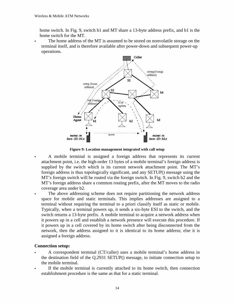
connection refer to static terminals, i.e. it is not necessary to determine dynamically a terminal’s current attachment point to the network before attempting to establish a connection to that terminal. However, with mobile ATM terminals, the location of such a terminal with respect to the network may no longer be deduced from its endpoint address. Additional addressing schemes and protocols are needed to locate and track mobile terminals, along with suitable modifications to the connection setup process. For example, in fig. 9, a connection is setup to the mobile in each of the two cells (under radio ports b1 and b3). Under a possible addressing architecture, the name m is resolved to an address b1.x, which is specified to radio port b1, in order to setup the first connection. The mobile then moves to the cell under radio port b3. When the second connection is being setup, the name m is resolved to the address b3.x identifying the current location.
3.2.1.1 Integrated Scheme
This is the most common scheme in WATM systems. The primitives for the scheme are proposed in [18]. They sketched out schemes for addressing mobile terminals, connection setup, location update and location caching.
Assigning addresses to MTs: �� A MT is assigned a unique “home” ATM address which does not change
regardless of which switch it currently uses to connect to the network. Each MT is associated with a home switch and the 13 byte routing prefix of a MT’s home address is supplied by the home switch. The MT’s home address is thus topologically significant, and a SETUP() message using MT’s home address will be routed via the
Wireless & Mobile ATM Networks
14
home switch. In Fig. 9, switch b1 and MT share a 13-byte address prefix, and b1 is the home switch for the MT.
�� The home address of the MT is assumed to be stored on nonvolatile storage on the terminal itself, and is therefore available after power-down and subsequent power-up operations.
Figure 9: Location management integrated with call setup
�� A mobile terminal is assigned a foreign address that represents its current attachment point, i.e. the high-order 13 bytes of a mobile terminal’s foreign address is supplied by the switch which is its current network attachment point. The MT’s foreign address is thus topologically significant, and any SETUP() message using the MT’s foreign switch will be routed via the foreign switch. In Fig. 9, switch b2 and the MT’s foreign address share a common routing prefix, after the MT moves to the radio coverage area under b2.
�� The above addressing scheme does not require partitioning the network address space for mobile and static terminals. This implies addresses are assigned to a terminal without requiring the terminal to a priori classify itself as static or mobile. Typically, when a terminal powers up, it sends a six-byte ESI to the switch, and the switch returns a 13-byte prefix. A mobile terminal to acquire a network address when it powers up in a cell and establish a network presence will execute this procedure. If it powers up in a cell covered by its home switch after being disconnected from the network, then the address assigned to it is identical to its home address; else it is assigned a foreign address.
Connection setup: �� A correspondent terminal (CT/caller) uses a mobile terminal’s home address in
the destination field of the Q.2931 SETUP() message, to initiate connection setup to the mobile terminal.
�� If the mobile terminal is currently attached to its home switch, then connection establishment procedure is the same as that for a static terminal.
Wireless & Mobile ATM Networks
15
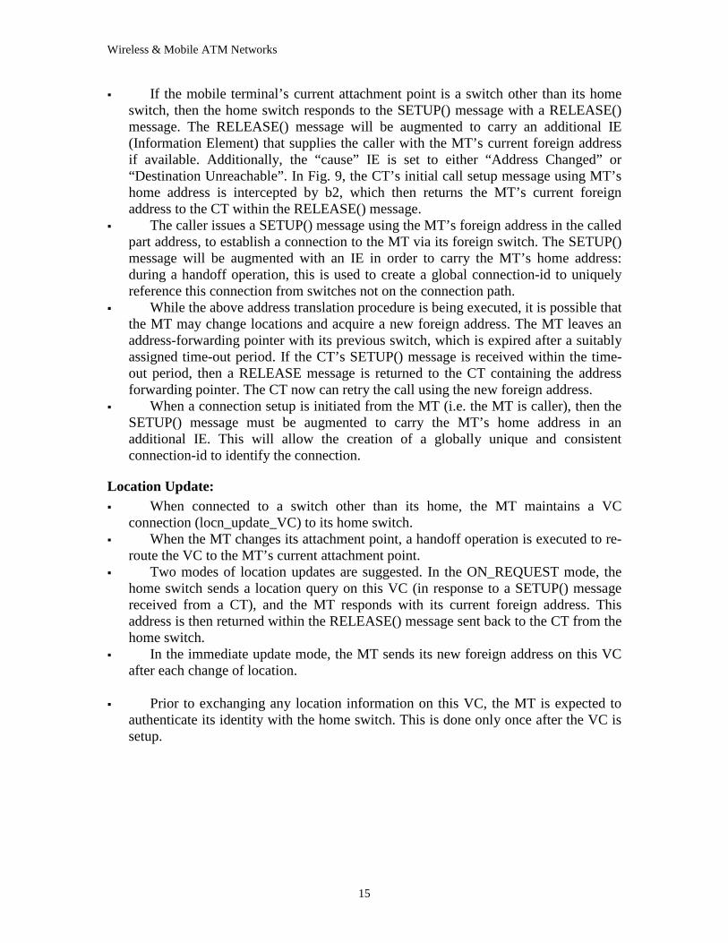
�� If the mobile terminal’s current attachment point is a switch other than its home switch, then the home switch responds to the SETUP() message with a RELEASE() message. The RELEASE() message will be augmented to carry an additional IE (Information Element) that supplies the caller with the MT’s current foreign address if available. Additionally, the “cause” IE is set to either “Address Changed” or “Destination Unreachable” . In Fig. 9, the CT’s initial call setup message using MT’s home address is intercepted by b2, which then returns the MT’s current foreign address to the CT within the RELEASE() message.
�� The caller issues a SETUP() message using the MT’s foreign address in the called part address, to establish a connection to the MT via its foreign switch. The SETUP() message will be augmented with an IE in order to carry the MT’s home address: during a handoff operation, this is used to create a global connection-id to uniquely reference this connection from switches not on the connection path.
�� While the above address translation procedure is being executed, it is possible that the MT may change locations and acquire a new foreign address. The MT leaves an address-forwarding pointer with its previous switch, which is expired after a suitably assigned time-out period. If the CT’s SETUP() message is received within the time-out period, then a RELEASE message is returned to the CT containing the address forwarding pointer. The CT now can retry the call using the new foreign address.
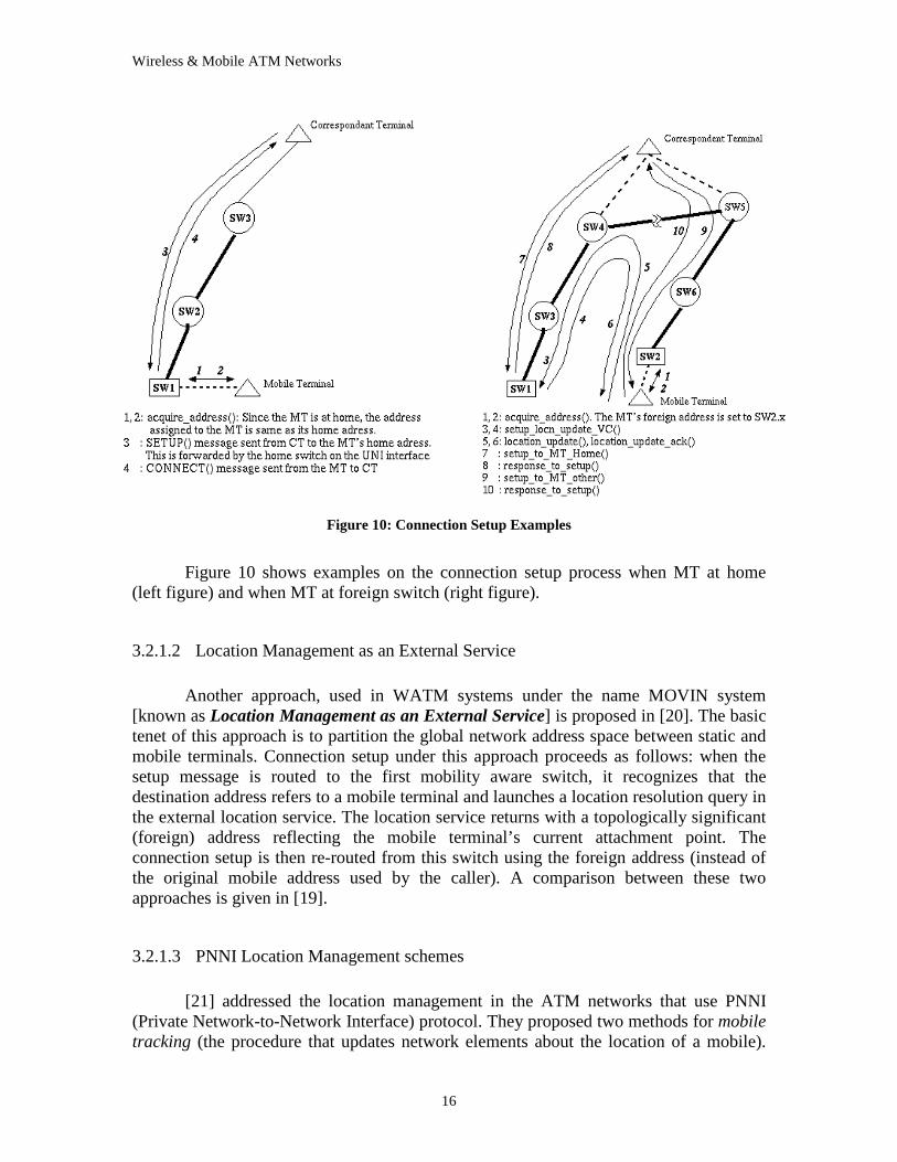
�� When a connection setup is initiated from the MT (i.e. the MT is caller), then the SETUP() message must be augmented to carry the MT’s home address in an additional IE. This will allow the creation of a globally unique and consistent connection-id to identify the connection.
Location Update: �� When connected to a switch other than its home, the MT maintains a VC
connection (locn_update_VC) to its home switch. �� When the MT changes its attachment point, a handoff operation is executed to re-
route the VC to the MT’s current attachment point. �� Two modes of location updates are suggested. In the ON_REQUEST mode, the
home switch sends a location query on this VC (in response to a SETUP() message received from a CT), and the MT responds with its current foreign address. This address is then returned within the RELEASE() message sent back to the CT from the home switch.
�� In the immediate update mode, the MT sends its new foreign address on this VC after each change of location.
�� Prior to exchanging any location information on this VC, the MT is expected to
authenticate its identity with the home switch. This is done only once after the VC is setup.
Wireless & Mobile ATM Networks
16
Figure 10: Connection Setup Examples
Figure 10 shows examples on the connection setup process when MT at home
(left figure) and when MT at foreign switch (right figure).
3.2.1.2 Location Management as an External Service
Another approach, used in WATM systems under the name MOVIN system
[known as Location Management as an External Service] is proposed in [20]. The basic tenet of this approach is to partition the global network address space between static and mobile terminals. Connection setup under this approach proceeds as follows: when the setup message is routed to the first mobility aware switch, it recognizes that the destination address refers to a mobile terminal and launches a location resolution query in the external location service. The location service returns with a topologically significant (foreign) address reflecting the mobile terminal’s current attachment point. The connection setup is then re-routed from this switch using the foreign address (instead of the original mobile address used by the caller). A comparison between these two approaches is given in [19].
3.2.1.3 PNNI Location Management schemes
[21] addressed the location management in the ATM networks that use PNNI
(Private Network-to-Network Interface) protocol. They proposed two methods for mobile tracking (the procedure that updates network elements about the location of a mobile).
Wireless & Mobile ATM Networks
17
And mobile location (the procedure by which a network node, typically the network switch of a calling party, determines the location of the mobile for the delivery for an incoming call).
Mobile PNNI Scheme �� When a connection setup is initiated from the MT (i.e. the MT is caller), then the
SETUP() message must be augmented to carry the MT’s home address in an additional IE. This will allow the creation of a globally unique and consistent connection-id to identify the connection. This approach simply enhances the PNNI routing protocol to handle mobile users. The current PNNI routing protocol specification allows for the exchange of reachability information about endpoints in a limited region of nodes within a Scope (S) within the switch of the moving mobile. There is no explicit mobile location phase prior to connection setup. Instead, connections are setup to mobiles according to the reachability information at the switches. Switches within the region defined by S (relative to the position of each mobile) have the correct reachability information for mobiles. Calls originating from such switches will be routed on the “shortest path” . However, calls originating at switches outside the region defined by S will be routed toward the home switch of the mobile, and subsequently forwarded to the current location of the mobile by using forwarding pointers.
�� Mobile tracking consists of first setting forwarding pointers at the home and old locations (in case of a move) of the mobile. Then a reachability update is sent from the new location to all nodes in the neighborhood of the new location defined by the parameter S, and from the old location to all nodes in the neighborhood of the old location.
�� Mobile locating is implicit with call setup in this scheme. Incoming calls to mobiles originating at nodes within the scope of the current (visiting) location of the mobile will be properly routed to the mobile. The mobile locating cost for such calls is 0. Calls originating at nodes outside this neighborhood will be routed to the home location of the mobile and then forwarded to the current location. Call setups to a mobile that were in progress while a user moves will reach the old location and are forwarded to the new location.
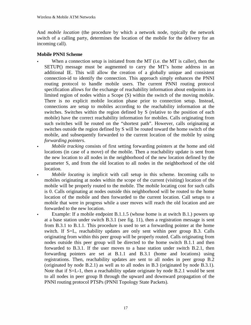
�� Example: If a mobile endpoint B.1.1.5 (whose home is at switch B.1.) powers up at a base station under switch B.3.1 (see fig. 11), then a registration message is sent from B.3.1 to B.1.1. This procedure is used to set a forwarding pointer at the home switch. If S=L, reachability updates are only sent within peer group B.3. Calls originating from within this peer group will be properly routed. Calls originating from nodes outside this peer group will be directed to the home switch B.1.1 and then forwarded to B.3.1. If the user moves to a base station under switch B.2.1, then forwarding pointers are set at B.1.1 and B.3.1 (home and locations) using registrations. Then, reachability updates are sent to all nodes in peer group B.2 (originated by node B.2.1) as well as to all nodes in B.3 (originated by node B.3.1). Note that if S=L-1, then a reachability update originate by node B.2.1 would be sent to all nodes in peer group B through the upward and downward propagation of the PNNI routing protocol PTSPs (PNNI Topology State Packets).
Wireless & Mobile ATM Networks
18
Figure 11: PNNI-based hierarchical ATM network
Location Registers (LR) Scheme �� This approach isolates the effect of mobility from the PNNI routing protocol by
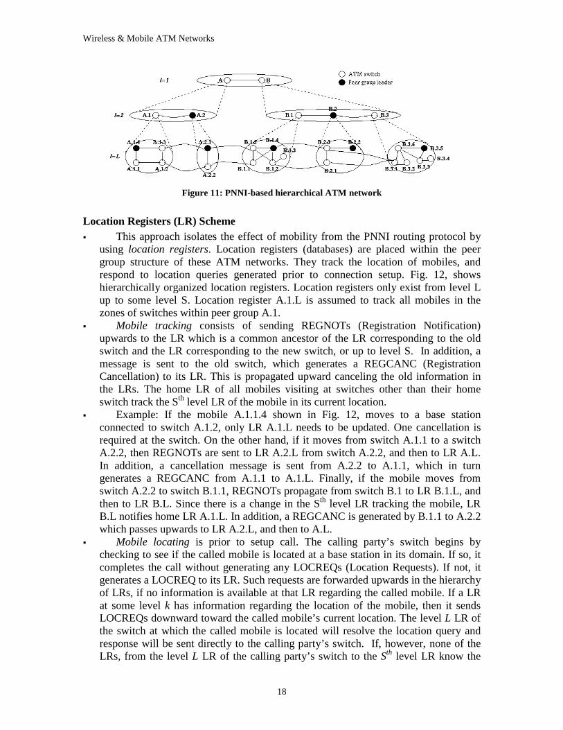
using location registers. Location registers (databases) are placed within the peer group structure of these ATM networks. They track the location of mobiles, and respond to location queries generated prior to connection setup. Fig. 12, shows hierarchically organized location registers. Location registers only exist from level L up to some level S. Location register A.1.L is assumed to track all mobiles in the zones of switches within peer group A.1.
�� Mobile tracking consists of sending REGNOTs (Registration Notification) upwards to the LR which is a common ancestor of the LR corresponding to the old switch and the LR corresponding to the new switch, or up to level S. In addition, a message is sent to the old switch, which generates a REGCANC (Registration Cancellation) to its LR. This is propagated upward canceling the old information in the LRs. The home LR of all mobiles visiting at switches other than their home switch track the Sth level LR of the mobile in its current location.
�� Example: If the mobile A.1.1.4 shown in Fig. 12, moves to a base station connected to switch A.1.2, only LR A.1.L needs to be updated. One cancellation is required at the switch. On the other hand, if it moves from switch A.1.1 to a switch A.2.2, then REGNOTs are sent to LR A.2.L from switch A.2.2, and then to LR A.L. In addition, a cancellation message is sent from A.2.2 to A.1.1, which in turn generates a REGCANC from A.1.1 to A.1.L. Finally, if the mobile moves from switch A.2.2 to switch B.1.1, REGNOTs propagate from switch B.1 to LR B.1.L, and then to LR B.L. Since there is a change in the Sth level LR tracking the mobile, LR B.L notifies home LR A.1.L. In addition, a REGCANC is generated by B.1.1 to A.2.2 which passes upwards to LR A.2.L, and then to A.L.
�� Mobile locating is prior to setup call. The calling party’s switch begins by checking to see if the called mobile is located at a base station in its domain. If so, it completes the call without generating any LOCREQs (Location Requests). If not, it generates a LOCREQ to its LR. Such requests are forwarded upwards in the hierarchy of LRs, if no information is available at that LR regarding the called mobile. If a LR at some level k has information regarding the location of the mobile, then it sends LOCREQs downward toward the called mobile’s current location. The level L LR of the switch at which the called mobile is located will resolve the location query and response will be sent directly to the calling party’s switch. If, however, none of the LRs, from the level L LR of the calling party’s switch to the Sth level LR know the
Wireless & Mobile ATM Networks
19
location of the called mobile, the Sth level LR sends a LOCREQ to the home LR of the called mobile. Since this LR tracks the Sth level LR of its mobiles, it forwards the LOCREQ to the Sth level LR tracking the mobile in its current location. This LR generates downward LOCREQs according to the information it has about the called mobile. Then a response is sent from the LR of the called mobile to the calling party’s switch.
Figure 12: Location Registers ar ranged hierarchically
�� Example: In figure 12, we consider calls that originate from B.2.2.5 and A.2.2.5 targeting A.1.2.3. First, when switch B.2.2 generates a LOCREQ for mobile A.1.2.3 to its location register B.2.L, the latter can immediately respond since A.1.2.3 is located within its region. In the second case, the LOCREQ sent by switch A.1.2 traverses the chain of the LRs, A.2.L and A.L. Since neither of these LRs have information on the location of the called mobile and l=S, A.L sends a LOCREQ to the home LR of the called mobile A.1.L. This LR forwards the LOCREQ to LR B.L. LOCREQs are then sent downward to LR B.2.L where the respond will be sent from.
3.2.2 Handoff (Handover) Control Once a connection has been established between a pair of endpoints, standard
protocols assume that the connection path does not change during the period of a connection lifetime (except due to failures of switches and links). This assumption is invalidated when the endpoint is mobile. The path of the connection for a mobile user needs to be frequently re-setup as the mobile user moves from one cell to another. For example, in figure 9, the connection that was setup to the mobile terminal through b1 is handed-off to b3, so there is a new path connecting S1 to b3 (the old path S1-b1 maybe contained completely or partially in this new path). Handoff protocols (scheme) are necessary to maintain the existing active connections. The main goal is to minimize latency, cell loss and to maintain efficient use of network resources and QoS for the rerouted call.
There are two types of handoff; Intra-switch Handoff and Inter-switch handoff. In
intra-cluster handoff, the end user moves from the zone of current radio port to a zone of another radio port within the same ATM switch. While in the Inter-switch handoff, the
Wireless & Mobile ATM Networks
20
end user moves from the covered zone of the current switch to a zone of a new switch. As we can see, in the first type the handoff process doesn’ t involve any ATM network switching. While in the second type, the handoff process requires rerouting at one or more ATM switches. This type of handoff is considered in this section.
The key issues in the design of efficient handoff protocols (schemes), as
mentioned in [20], are: �� During the process of re-routing an active connection, we need to ensure that,
minimal cells are lost. �� Before a mobile terminal can switch to a new radio port, we need to determine that
the quality of services (QoS) contracts for the existing connection can be met at the new radio port.
�� A mobile terminal may have multiple active connections to one or more terminals when it makes a move. The connections can either be re-routed individually or may be re-routed/extended as a group.
The explanation of the requirements of the handover protocol (e.g. handover latency, QoS, signaling traffic, data integrity, and others) is discussed in [28].
3.2.2.1 Full Re-establishment scheme:
This is the simplest and most intuitive scheme. In this scheme, the base station of the newly visited wireless cell will establish new connections for the mobile endpoint to the destination hosts. This method, however, requires a lot of handover signaling and the destination host has to be involved in the re-establishment of a completely new path. This scheme therefore results in high connection setup latency, poor reuse of network resources and causes severe interruptions to traffic flow.
3.2.2.2 Path Extension scheme:
This scheme consists of extending an active connection from the terminal's current radio port to the next radio port. The idea here is that after handoff, the new connection consists of the existing connection from the source to the old base station followed by an additional sub-path (the extension part) from the old base station to the new base station. For example, in figure 9, the new path will consist of S-b1 (the original path) and b1-b3 (the extension path). This approach offers the advantage that: a) it is simple, b) there is no need to buffer and transfer cells between the old base station and the new one along a separate base-to-base connection (this connection will be used in the later scheme), c) the handoff disruption delay is consequently smaller than the later approach, d) the existing path is maximally reused.
However, the extended path also increases the end-to-end delay and reduces network utilization since the extended path may traverse the same link more than once, i.e. loops may be created. A possible solution, proposed in [20], is to optimize the path lazily after completion of handoff using additional hardware support at switches: as follow:
- "Looping" points (switches) are detected during the path extension process.
Wireless & Mobile ATM Networks
21
- Loops are removed by sending a specially defined OAM cell from a looping point.
- While the OAM cell is traversing the loop, incoming cells on the connection are buffered locally at the looping point, and then forwarded on the optimized path after the loop has been removed.
To reduce the delay, it is not necessary to perform the loop-removal procedure on a per-move basis, and instead could be performed after k moves.
Since the SWAN system is proposed for LAN system which means that most of a
mobile's movement will be within a local domain, they use this approach in their handoff scheme. They detect and eliminate the loop when the same base station appears twice in the path.
3.2.2.3 Partial Path Re-routing (Incremental Re-establish) scheme:
Basic Concepts: This approach is based on removing a part of the existing connection and adding a
new sub-path from the point of detachment, the crossover (handoff) switch. For example, in figure 9, when the mobile terminal moves from b1 to b3, the portion of the existing connection from the handoff switch (S2) to b1 is deleted and a new sub-path from S2 to b3 is spliced in the remainder of the connection (from the source to the handoff switch). The network entities involving in the handoff control process are: 1) Mobile terminal (MT). 2) Corresponding terminal (CT) which is the host at the other end of the connection. In most of cases, it does not notice the handoff control procedure. 3) Original base station (old base station) which covers the area where MT is currently located (in the following we assume that the base stations act also as switches). 4) New base station which covers the area where MT is about to enter. 5) Crossover switch (COS), named also as Handoff switch (HOS) which represent the diverge point of the current path of the connection through the old base station and the new path of the connection through the new base station.
The main steps in the handoff procedure, as proposed in [8], are as follows (assuming there is a group of virtual connections to the moving mobile terminal):
- New base station identification: Both the mobile terminal and the base stations
can coordinate the selection. - Handoff switch (HOS) selection: The handoff switch can be selected based on the
route optimization from multiple connections, and a series of QoS considerations. The easiest selection is the current switch serving the mobile terminal as all connections to the mobile terminal transit this switch. In this case, the scheme will be similar to the path extension scheme.
- New mobile segments establishment: A group of new mobile segments are established together between the HOS and the new base station, and the new base station can allocate the wireless resources for the mobile terminal before actual handoff.
Wireless & Mobile ATM Networks
22
- VC re-routing: The HOS re-routes the connections by connecting the original static segments to the new mobile segments. At the same time, the old base station instructs the mobile terminal to switch to the new base station.
- Cell re-sequencing: The old base station transfers the wireless DLC state information to the new base station. This guarantees the in-sequence delivery of ATM cells. A typical DLC state, as mentioned in [8], includes VCI, traffic class information, transmission and reception tables, outstanding cell sequence numbers and datalink cell buffers.
- Route optimization: Optionally, route optimization can be treated separately from the handoff process, as long as the HOS provides reasonable robustness to avoid obvious loops.
Signaling Modification:
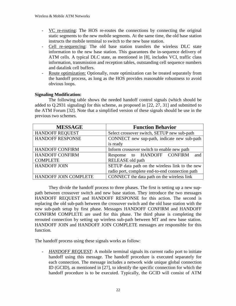
The following table shows the needed handoff control signals (which should be added to Q.2931 signaling) for this scheme, as proposed in [22, 27, 31] and submitted to the ATM Forum [32]. Note that a simplified version of these signals should be use in the previous two schemes.
MESSAGE Function Behavior
HANDOFF REQUEST Select crossover switch, SETUP new sub-path HANDOFF RESPONSE CONNECT new sup-path, indicate new sub-path
is ready HANDOFF CONFIRM Inform crossover switch to enable new path HANDOFF CONFIRM COMPLETE
Response to HANDOFF CONFIRM and RELEASE old path
HANDOFF JOIN SETUP data path on the wireless link to the new radio port, complete end-to-end connection path
HANDOFF JOIN COMPLETE CONNECT the data path on the wireless link They divide the handoff process to three phases. The first is setting up a new sup-
path between crossover switch and new base station. They introduce the two messages HANDOFF REQUEST and HANDOFF RESPONSE for this action. The second is replacing the old sub-path between the crossover switch and the old base station with the new sub-path setup by first phase. Messages HANDOFF CONFIRM and HANDOFF CONFIRM COMPLETE are used for this phase. The third phase is completing the rerouted connection by setting up wireless sub-path between MT and new base station. HANDOFF JOIN and HANDOFF JOIN COMPLETE messages are responsible for this function.
The handoff process using these signals works as follow:
- HANDOFF REQUEST: A mobile terminal signals its current radio port to initiate
handoff using this message. The handoff procedure is executed separately for each connection. The message includes a network wide unique global connection ID (GCID), as mentioned in [27], to identify the specific connection for which the handoff procedure is to be executed. Typically, the GCID will consist of ATM
Wireless & Mobile ATM Networks
23
addresses of both endpoints, plus an additional pair of identifiers (to distinguish multiple connections between the same pair of end points).
- HANDOFF RESPONSE: the current radio port indicates to the mobile terminal that a connection sub-path has been established to the new radio-port. The message includes the connection GCID. During this phase of handoff request and response, the mobile terminal continues to receive and transmit data via its current radio-port.
- HANDOFF CONFIRM: The mobile terminal informs its current radio port that it is ready to switch to the new radio port for the specific connection identified by the GCID. At this time, the mobile terminal stops transmitting cells to its current radio port. The message is propagated up to the crossover switch, which then shifts the data path to the new connection segment.
- HANDOFF COMPLETE: As the HANDOFF CONFIRM message propagates from the COS to the current radio port, the existing connection segment between the COS and the radio port is released. It is then forwarded to the mobile terminal indicating that the mobile terminal may now switch to the new radio port.
- HANDOFF JOIN: Once the mobile terminal has received a HANDOFF CONFIRMATION message for each of its connections, it changes its operating radio frequency to that of the new radio port. For each connection, it then sends a HANDOFF JOIN to the new radio-port to close the loop on the signaling path.
- HANDOFF JOIN COMPLETE: The radio port informs the mobile of the VC number to use on the new link. At this time, the mobile terminal may begin to send/receive cells under the new radio port.
In addition to these messages, some existing hop-by-hop ACK messages are used
for handoff control. CALL PROCEEDING is a response to HANDOFF REQUEST when the new path is being SETUP. CONNECT ACK is a response to HANDOFF RESPONSE (also HANDOFF JOIN COMPLETE) when the new path is being CONNECT. RELEASE COMPLETE is a response to HANDOFF CONFIRMATION COMPLETE when the old path is being RELEASE.
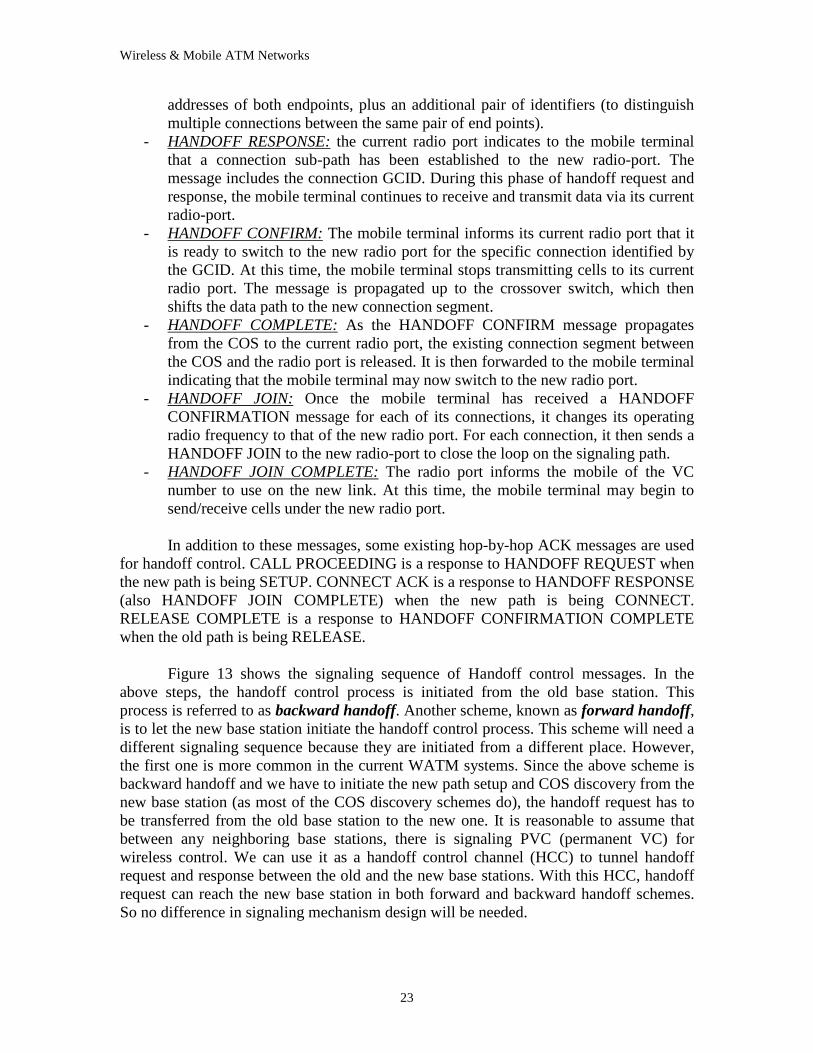
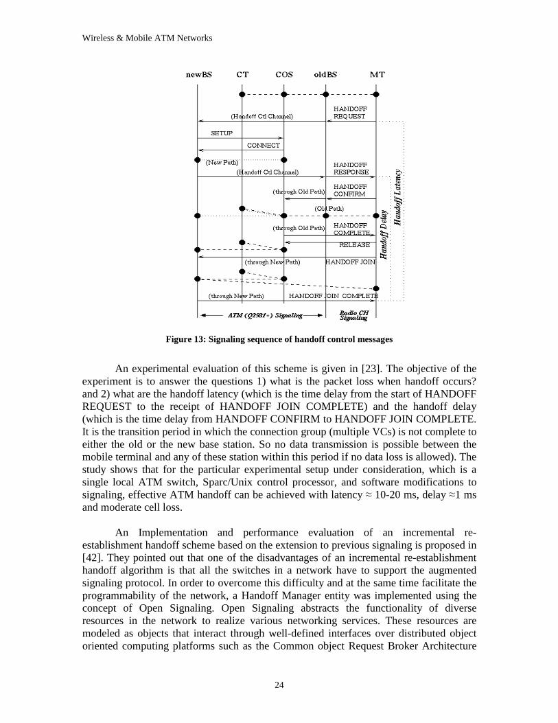
Figure 13 shows the signaling sequence of Handoff control messages. In the
above steps, the handoff control process is initiated from the old base station. This process is referred to as backward handoff. Another scheme, known as forward handoff, is to let the new base station initiate the handoff control process. This scheme will need a different signaling sequence because they are initiated from a different place. However, the first one is more common in the current WATM systems. Since the above scheme is backward handoff and we have to initiate the new path setup and COS discovery from the new base station (as most of the COS discovery schemes do), the handoff request has to be transferred from the old base station to the new one. It is reasonable to assume that between any neighboring base stations, there is signaling PVC (permanent VC) for wireless control. We can use it as a handoff control channel (HCC) to tunnel handoff request and response between the old and the new base stations. With this HCC, handoff request can reach the new base station in both forward and backward handoff schemes. So no difference in signaling mechanism design will be needed.
Wireless & Mobile ATM Networks
24
Figure 13: Signaling sequence of handoff control messages
An experimental evaluation of this scheme is given in [23]. The objective of the
experiment is to answer the questions 1) what is the packet loss when handoff occurs? and 2) what are the handoff latency (which is the time delay from the start of HANDOFF REQUEST to the receipt of HANDOFF JOIN COMPLETE) and the handoff delay (which is the time delay from HANDOFF CONFIRM to HANDOFF JOIN COMPLETE. It is the transition period in which the connection group (multiple VCs) is not complete to either the old or the new base station. So no data transmission is possible between the mobile terminal and any of these station within this period if no data loss is allowed). The study shows that for the particular experimental setup under consideration, which is a single local ATM switch, Sparc/Unix control processor, and software modifications to signaling, effective ATM handoff can be achieved with latency � 10-20 ms, delay �1 ms and moderate cell loss.
An Implementation and performance evaluation of an incremental re-
establishment handoff scheme based on the extension to previous signaling is proposed in [42]. They pointed out that one of the disadvantages of an incremental re-establishment handoff algorithm is that all the switches in a network have to support the augmented signaling protocol. In order to overcome this difficulty and at the same time facilitate the programmability of the network, a Handoff Manager entity was implemented using the concept of Open Signaling. Open Signaling abstracts the functionality of diverse resources in the network to realize various networking services. These resources are modeled as objects that interact through well-defined interfaces over distributed object oriented computing platforms such as the Common object Request Broker Architecture
Wireless & Mobile ATM Networks
25
(CORBA). The Handoff Manager could reside on any node connected to the network while freeing the switches from the additional load of handling handoff requests and responses. The Handoff Manager is modeled as a centralized controller that manages the re-routing and COS selection functions. It receives handoff requests from the BSs via CORBA calls on its methods and processes them according to the handoff algorithm used. It re-routes connections using the Dijkstra’s shortest path algorithm to obtain the optimal routes and also to select the COS. It then communicates with the switches via the Simple Network Management Protocol (SNMP) to map the new routes into their VC routing tables. For the experimental results and more details refer to [42].
Crossover Switch discovery: The selection of COS varies largely because of different performance and
complexity criteria for a handoff control process. The major criterias, as mentioned in [25], are:
1) Protocol Complexity: How much more computing power is required. 2) Handoff latency: Connection setup latency in ATM networks is a function of
many factors, such as signaling protocol overhead, the signal propagation delay, the number of hops, the number of connection request, etc. While the number of connection requests is application dependent, the signaling protocol overhead depends on the connection setup protocol. However the number of hops required to set up the partial path during a handover is crossover switch discovery dependent. So to reduce the connection setup latency we have to reduce the number of hops required to set up the partial path during handovers. End-to-end latency is a function of the route length. If the new route becomes longer after each handover, then the end-to-end latency will be increased.
3) Network resource utilization: During the lifetime of a connection, several links are utilized to support the traffic. Having multiple hops for a connection mean that more links are utilized and this increases the probability of new call blocking and network congestion. In particular, for calls with excessive capacity demands, fewer hops alleviate the overall link utilization. This explains why circuit reuse and shorter new paths are taken into consideration during the crossover switch discovery.
The main purpose of COS discovery is to derive a minimum-hop path from the
new base station (newBS) to the COS, where COS is a node in the original mobile terminal (MT) to corresponding terminal (CT) path. In addition, shorter resultant path and circuit reuse also governs the selection of a COS. To achieve these requirements, COS discovery utilizes network routing information to compute suitable COS. The COS discovery methods proposed in [25] are: - Loose Select discovery: In this COS discovery algorithm, the minimum-hop path from
newBS to CT is computed. This is achieved by querying the location server for
Wireless & Mobile ATM Networks
26
the CT address with the target host address provided by the migrating MT during handovers. The existence of the original MT-to-CT path nodes is not taken into consideration during the COS selection process. If the chosen path from newBS to CT has, however, shared some part of the original path, then the convergence will occur at that point.
- Prior Knowledge discovery: Unlike the above discovery, this method has prior access to information about the nodes in the original MT-to-CT path for convergence. This information can be obtained from the connection server. COS selection is made at the newBS, with each node in the existing path taken as its destination. The minimum-hop routes from newBS to these destinations are then computed and the node with the least hop count among these convergence paths will be chosen as the COS. However, if multiple potential COSs have the same minimum-hop count then the node nearest to the oldBS will be chosen for convergence.
- Prior Path Optimal Resultant discovery: Similar to prior path knowledge discovery, all the possible convergence paths from newBS to the COSs are computed. For each of the newBS, number of hops in the paths computed, it is compared to its old path, i.e. number of hops to oldBS. Only those convergence paths that are equal or shorter than their receptive old partial paths will be valid. Among these valid paths, the minimum-hop convergence path will be chosen. In case of equality we apply the same method in the previous discovery method.
- Distributed hunt discovery: This discovery is distributed in the sense that it requires each node to maintain a list of currently active connections which is updated as a result of connection setup and tear down of its own connections and its immediate neighbor's connections. Since the newBS can not be a COS, it will have to initiate a COS discovery broadcast to discover which nodes residing in the backbone network are possible COSs. Among these possible COSs, the node with least number of hops to newBS will be chosen as the COS. So, this scheme does not need to know where the CT is (since once CX is found, connectivity to the CT is automatically assured) and consultations with the connection or location servers are not necessary.
- Backward tracing discovery: It is a mechanism whereby the newBS triggers the oldBS to invoke a distributed crossover point location process. This crossover location algorithm backtracks along the original MT-to-CT route, one hop at a time, starting from oldBS. Each node along this route will check its routing table to ascertain whether it is the CX. If the node uses the same port to reach both old and new BSs, then the switch one hop in the down-link direction is the COS. This COS then sets up the partial circuits to the new BS.
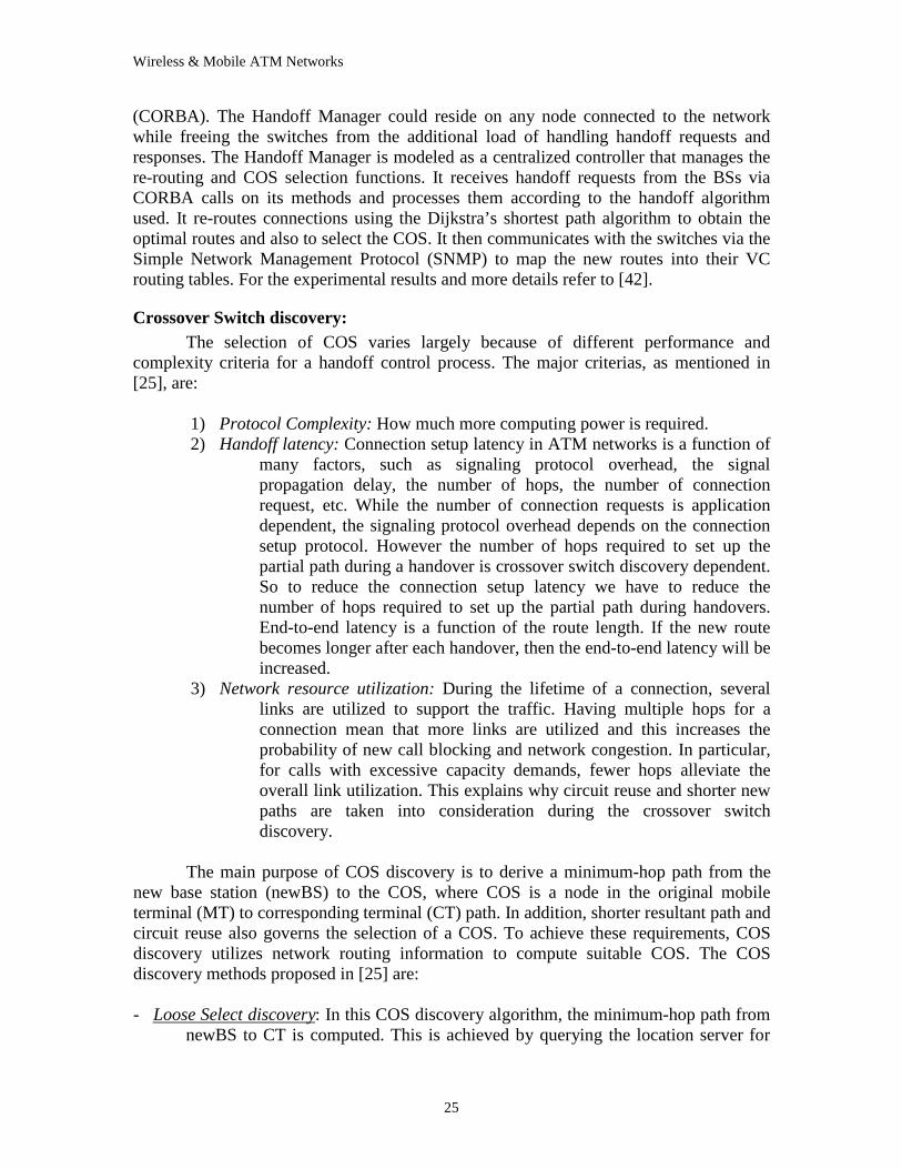
Also [22] summarized other methods (some are similar to the above schemes) to
select COS as shown in figure 14. As we can see, when the scheme complexity is our concern, the Extended-NewPath scheme should be used, which chooses oldBS as the COS regardless to network topology. So there is no need for dynamically computing COS according to the connection's route configuration. For smaller handoff latency, the Minimum-NewPath protocol may be used. It chooses the switch that is closest to the original connection as the COS. However, it is not practical because finding the COS
Wireless & Mobile ATM Networks
27
itself may need much more signaling effort than setting up a new path. An alternative protocol First Diverge can be an approximate approach for the smaller handoff latency. It chooses the COS as the first switch from which CT and newBS are going in different ways. If network resources is the primary criterion, the Last Diverge protocol maybe used. It gives an optimal route for the whole connection. An approximation for this approach is First-Cross-to-CT scheme. Although this method may not give an optimal new path, it is nearly optimal and obviously has less signaling cost. With the consideration of PNNI hierarchical structure, the COS may be chose as Fixed-Anchor within a peer group as a compromise between handoff latency and network resource occupancy. This method comes up with the problem of how to choose the fixed anchors at different levels of peer groups.
Figure 14: Crossover switch (COS) selections for handoff
Cell Synchronization: During changing the path that data should follow in the handover process, cells
could be lost, duplicated, or/and miss ordering. Since the ATM cell doesn't contain any information to detect the duplication or the misordering of the cells, procedures should be proposed to solve this problem. Although, the lost cell will be retransmitted, this cause an overhead in the system. Some methods should propose the solution for that problem.
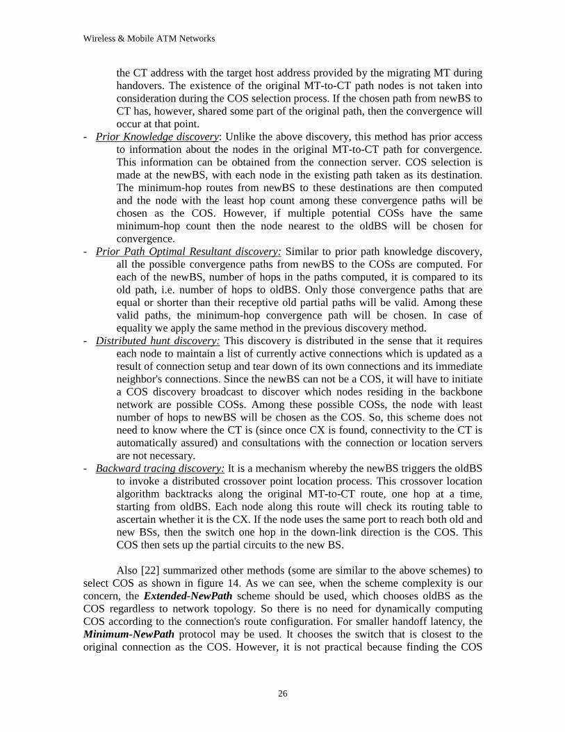
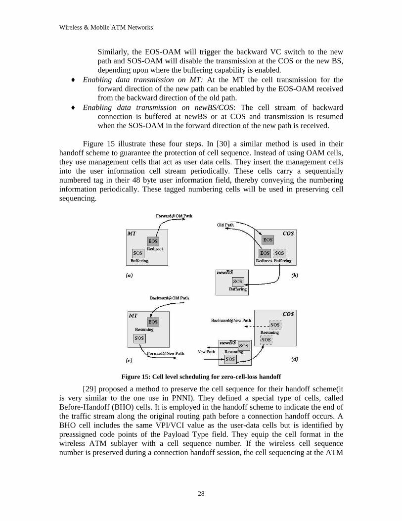
A method for zero-cell-loss is proposed in [24]. They proposed a cell level
scheduling procedure in four steps as follow: ♦ Inserting OAMs and buffering cell stream at MT: At MT the forwarded data
stream is re-directed to the new path by inserting an EOD-OAM and a SOS-OAM. The EOS-OAM will trigger the VC switch to the new path and the SOS-OAM will disable the transmission at MT and buffer the following cells on a specific queue.
♦ Inserting OAMs at COS and buffering data stream at COS or newBS: After the COS receives the EOS cell from the old path in the forwarded direction, an EOS-OAM followed by SOS-OAM is inserted into the backward connection.
Wireless & Mobile ATM Networks
28
Similarly, the EOS-OAM will trigger the backward VC switch to the new path and SOS-OAM will disable the transmission at the COS or the new BS, depending upon where the buffering capability is enabled.
♦ Enabling data transmission on MT: At the MT the cell transmission for the forward direction of the new path can be enabled by the EOS-OAM received from the backward direction of the old path.
♦ Enabling data transmission on newBS/COS: The cell stream of backward connection is buffered at newBS or at COS and transmission is resumed when the SOS-OAM in the forward direction of the new path is received.
Figure 15 illustrate these four steps. In [30] a similar method is used in their
handoff scheme to guarantee the protection of cell sequence. Instead of using OAM cells, they use management cells that act as user data cells. They insert the management cells into the user information cell stream periodically. These cells carry a sequentially numbered tag in their 48 byte user information field, thereby conveying the numbering information periodically. These tagged numbering cells will be used in preserving cell sequencing.
Figure 15: Cell level scheduling for zero-cell-loss handoff
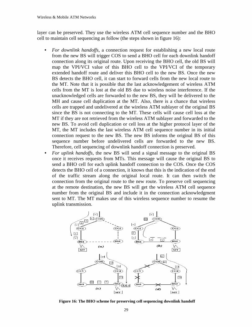
[29] proposed a method to preserve the cell sequence for their handoff scheme(it is very similar to the one use in PNNI). They defined a special type of cells, called Before-Handoff (BHO) cells. It is employed in the handoff scheme to indicate the end of the traffic stream along the original routing path before a connection handoff occurs. A BHO cell includes the same VPI/VCI value as the user-data cells but is identified by preassigned code points of the Payload Type field. They equip the cell format in the wireless ATM sublayer with a cell sequence number. If the wireless cell sequence number is preserved during a connection handoff session, the cell sequencing at the ATM
Wireless & Mobile ATM Networks
29
layer can be preserved. They use the wireless ATM cell sequence number and the BHO cell to maintain cell sequencing as follow (the steps shown in figure 16):
• For downlink handoffs, a connection request for establishing a new local route
from the new BS will trigger COS to send a BHO cell for each downlink handoff connection along its original route. Upon receiving the BHO cell, the old BS will map the VPI/VCI value of this BHO cell to the VPI/VCI of the temporary extended handoff route and deliver this BHO cell to the new BS. Once the new BS detects the BHO cell, it can start to forward cells from the new local route to the MT. Note that it is possible that the last acknowledgement of wireless ATM cells from the MT is lost at the old BS due to wireless noise interference. If the unacknowledged cells are forwarded to the new BS, they will be delivered to the MH and cause cell duplication at the MT. Also, there is a chance that wireless cells are trapped and undelivered at the wireless ATM sublayer of the original BS since the BS is not connecting to the MT. These cells will cause cell loss at the MT if they are not retrieved from the wireless ATM sublayer and forwarded to the new BS. To avoid cell duplication or cell loss at the higher protocol layer of the MT, the MT includes the last wireless ATM cell sequence number in its initial connection request to the new BS. The new BS informs the original BS of this sequence number before undelivered cells are forwarded to the new BS. Therefore, cell sequencing of downlink handoff connection is preserved.
• For uplink handoffs, the new BS will send a signal message to the original BS once it receives requests from MTs. This message will cause the original BS to send a BHO cell for each uplink handoff connection to the COS. Once the COS detects the BHO cell of a connection, it knows that this is the indication of the end of the traffic stream along the original local route. It can then switch the connection from the original route to the new route. To preserve cell sequencing at the remote destination, the new BS will get the wireless ATM cell sequence number from the original BS and include it in the connection acknowledgment sent to MT. The MT makes use of this wireless sequence number to resume the uplink transmission.
Figure 16: The BHO scheme for preserving cell sequencing downlink handoff
Wireless & Mobile ATM Networks
30
3.2.2.4 Handoff in Multicast Connection:
[34] proposed a handover mechanism for multicast connections in ATM LAN systems. They used a variation of the partial re-routing scheme mentioned above. They introduced the concept of distribution point (DP). A DP is an ATM switch that performs a minimum of dualcast action for a multicast connection. ATM cells are duplicated and distributed by the DP to each of the group’s receivers. An enhanced version of the Prior Path discovery algorithm will be use for COS discovery. If COS is not DP, then the connection re-routing (at the COS) is similar to unicast-connection handovers and is achieved via association join and disjoin operation. However, if the chosen COS happens to be DP, then the connection re-routing process comprises of multicast-leave (to prune the old branch of the multicast tree) and multicast-join (to join a new branch to an existing multicast tree) operations. The handover steps are summarized as follow:
• MT sends a hint message to the oldBS when it detects a handover action. Then, oldBS sends an invoke message to newBS to execute the COS discovery algorithm.
• The newBS queries the connection server (in case of centralized connection management), or by sending a query message throughout the LAN (in case of distributed connection management), for a list of all possible COS nodes.
• The newBS proceeds to locate a distribution point which is nearest to the MT. Then the newBS inspects DP’s routing table for the minimum-hop routes from newBS to the nodes in the oldBS–DP path.
• The COS discovery process locates the COS with the minimum-hop path from newBS among all the possible COS’s. Note that the COS must be on the oldBS-DP path.
• newBS establish the new partial path to COS either using connection server(centralized case) or using setup control packets (distributed case). Then it waits the MT to signal a greet message once MT enters the new wireless cell.
• Upon receiving the greet message, newBS sends a redirection message to the COS. To activate the appropriate connection re-routing operations, the COS must first verify it is the DP or not to take the appropriate action as mentioned previously.
• The COS proceeds to relinquish the old partial path. The deletion operation can be performed in parallel with the join and greet acknowledgement messages.
Another protocol to support the handoff process for multicasting connection in PNNI ATM network is proposed in [35]. They limit the scope of research for the leaf movement not the root. They defined an Entry Border Node of a peer group as it is, from the upstream of connection, the first node in the peer group which is on the Point to Multipoint (PMP) connection tree. The main steps in the handoff process as is mentioned in the paper are:
• Resource registration on newBS: A MT registers on the newBS to obtain resources, such as ATM address, signaling PVCs, radio frequency. The MT
Wireless & Mobile ATM Networks
31
may not need a full registration to the newBS as it boots up, but the resources availability must be checked before data connection’s handoff.
• COS discovery: The selection of COS for a PMP connection is very restrictive. A node has be an entry border node whose peer group covers the newBS, in order for the node to be qualified as a COS. There is two ways of signaling for COS discovery, i.e. signaling either from the newBS or from the oldBS. In both cases, the signaling message for COS discovery must pass to an entry border node of the peer group which covers the newBS.
• Adding the NewLeaf: Each leaf is uniquely identified in the PMP tree with an Endpoint Reference for connection trace purposes, when a leaf is added on the tree, and endpoint reference is stored in the nodes from the root to the node that the leaf attached. The endpoint references for a leaf forms a path from the root to the leaf called Leaf’s Path. In order to find the new leaf path, a message is sent toward the newBS containing a Handoff Control information element (HCIE). It is only responsible to establish the path from the COS to the newBS.
• Cell synchronization: In order to avoid cell loss or duplication, an OAM cell called Handoff Cell Synchronization (HOSYN) OAM has been introduced. After the new path for the MT is added from COS to newBS, the (HOSYN) OAM cell is inserted to the input VC on COS. Both the oldBS and the newBS can receive this marker cell. When the newBS receives that cell, it knows a specific mobile terminal is in handoff process. It will buffer the cell stream after HOSYN until a control message is received from the MT.
• Dropping the OldLeaf: When the MT at the oldBS receives the HOSYN, it can send a DROP PARTY request to the root. This message has also a HCIE. The message goes up to the COS or MT’s proxy root, whichever is reached first.
• Completing the new path: The NewLeaf is virtually added at the newBS. A HANDOFF JOIN message is used to release the cell stream buffering on the newBS. MT sends the message to the newBS. Upon receiving the message, the newBS releases all the buffering for the MT, including both point to point, and point to multipoint connections.
3.2.2.5 Other Handoff schemes:
A modified incremental re-establishment scheme, Multicast Join, uses the multicasting feature of ATM switches to allow a new partial path to be branched out from a multicast tree rooted at the COS. In this scheme, the transient period from confirmation of handoff request to the completion of handoff joining, the downlink data is sent to both the old base station and the new base station.
To implement a fast handoff process by avoiding connection re-establishment on handoff, Virtual Tree architecture is proposed [15] and implemented in some LAN systems as in [17]. The basic idea is to allocate a collection of virtual channel connections for each call at setup time, each to be used between the mobile and a base station, for all base stations in the domain. At handoff, the mobile simply picks the appropriate pre-established virtual channel and begins transmission to the new base station. The root,
Wireless & Mobile ATM Networks
32
which all TAM cells in a domain go through, monitors the virtual connection numbers to determine the current base station serving a mobile.
Wireless & Mobile ATM Networks
33
4 Conclusion and Future Work In this paper, the motivations for wireless ATM networks have been mentioned.
The service requirements have also been stated. The general model architecture of wireless ATM has been presented with the possible current variations and the differences between the implemented WATM systems. In the second section of the paper, a survey on the design issues of WATM was given. I showed the new extended layers of the WATM with the functions of each sublayer within these layers. Protocols for radio physical layer, medium access control layer, data link layer, and wireless control layer has been presented as describing the sublayers within the radio access layer. Also, different schemes for location management and handoff control were given in the section that described the mobility extension in ATM network.
There are still other important issues in wireless ATM network systems that
should be considered for further research. For example, when the WATM system is an ATM-based satellite network [36], a new protocol for radio access layer should be proposed to accommodate the system constraints and limitations. Also a few applications dealt with other kinds of ATM switches. For example, in the systems that the ATM switches are mobile and the end users are also mobile or fixed with respect to certain switch as in [37], a different scheme and protocols should be proposed for the mobility extensions of the wireless system. Also wireless ATM QoS needs further consideration and researching.
A new trend for wireless and mobile ATM networks is to enable network entities
to perform adaptive behavior and becoming intelligent, capable of making various decisions with autonomy. Examples of that trend could be found in [39], [40], and [41].
In [39], intelligent agents will be installed in all base stations, mobile stations and ATM switches. Every agent will communicate with its neighboring agents via Operations and Maintenance (OAM) cells. The agent in each base station will observe traffic evolution and provide a better allocation of resources according to its knowledge and rule-based information. The network operation will be dynamic and depend only on the actual traffic conditions. Detected patterns in the traffic evolution through observation will be added to the agent’s knowledge database. Give this learned knowledge, fast decisions with less signaling for identified periodic traffic can be provided. Two applications, the adaptive channel assignment and BER optimization, using these intelligent agents have been studied in that paper.
Another method to integrate intelligent network concepts in mobile ATM networks is proposed in [40]. In this method, intelligent entities are considered as ATM terminals. All their interactions are based on the intelligent network application protocol (INAP) and transported as if they are simple exchanged data. The paper proposed some heuristic solutions, based on intelligent node’s interactions, to implement some complementary services that are essential for ATM network managers and user needs.
The idea of Active (Programmable) Networks has been adapted to ATM mobile network in [41]. That paper discussed the design, implementation, and evaluation of an open programmable mobile network based on distributed object technology called
Wireless & Mobile ATM Networks
34
mobiware that dynamically exploits the intrinsic scalable properties of an adaptive mobile application.
Wireless & Mobile ATM Networks
35
5 References
[1] D. Raychaudhuri, ATM based transport architecture for multiservices wireless personal communication networks, IEEE J. Selected Areas in Communications Oct.(1994)1401-1414
[2] D. Raychaudhuri, Wireless ATM: An enabling technology for multimedia personal communication, Wireless Network 2(1996) 163-171
[3] Geert Awater and Jan Kruys, Wireless ATM - an overview, Mobile Networks and Applications 1(1996)235-243
[4] D. Raychaudhuri, WIRELESS ATM NETWORKS: Architecture, System Design and Prototyping, IEEE Personal Communication Magazine, August(1996)
[5] Stephen Bush and et al, A control and management network for wireless ATM systems, Wireless Networks 3(1997)267-283
[6] Ruixi Yuan, et al, A Signaling and Control Architecture for Mobility Support in Wireless ATM Networks, Mobile Networks and Applications, 1(1996)287-298
[7] P. Agrawal, E. Hyden, et al, SWAN: A Mobile Multimedia Wireless Network, IEEE Personal Communications, April(1996)
[8] D. Raychaudhuri, et al, WATMnet: A Prototype Wireless ATM System for Multimedia Personal Communication, IEEE J. Selected Areas in Communications, Jan(1997)83-95
[9] R. Acharya, Jun Li and D. Raychaudhuri, Mobile ATM: Architecture, Protocols and Implementation, 2nd International IEEE Workshop on Broadband Switching Systems, Dec(1997)
[10] D. Raychaudhuri, Design and Performance of Radio Access Protocols in WATMnet, a Prototype Wireless ATM Networks, ICUPC 97 6th WINLAB Workshop;Proceedings of ICUPC 97 6th Winlab Workshop
[11] D. Gilmuttay, et al, Wireless ATM Radio Access Layer Requirements, ATM Forum/96-1057, August(1996)
[12] X. Qiu, V. Li and Ji-Her Ju, A multiple access scheme for multimedia traffic in wireless ATM, Mobile Networks and Applications 1(1996)259-272
[13] J. Chen, K. Sivalingam and R. Acharya, Comparitive analysis of wireless ATM channel access protocols supporting multimedia traffic, Mobile Networks and Applications 3(1998) 293-306
[14] S. Aikawa, Y. Motoyama and M. Umehira, Error correction and error detection techniques for wireless ATM systems, Wireless Networks 3(1997)285-290
[15] I. Katzela and M.Veeraraghavan, Virtual tree routing protocols for a wireless ATM LAN, Proc. of IEEE ICUPC'96, Sept. 1996
Wireless & Mobile ATM Networks
36
[16] S. Ramanathan and M. Steenstrup, A survey of routing techniques for mobile communications networks, Mobile Networks and Applications 1(1996) 89-104
[17] M. Sun and K. Vastola, MOVIN – A mobile ATM architecture for fast handoff, International Journal on Wireless Information Networks
[18] A. Acharya, J. Li, D. Raychaudhuri, Primitives for Location Management and Handoff in Mobile ATM Networks , ATM Forum/96-1121, Oct. 96
[19] A. Acharya, Comparison of location management schemes for mobile ATM, ATM Forum/96-0161, Feb. 1997
[20] A. Acharya, et al, Handoff and Location Management in Mobile ATM Networks, 3rd International Workshop. on Mobile Multimedia Communications (MoMu-C3), September 1996
[21] M. Veeraraghavan, G. Dommety, et al, Location management in wireless ATM networks, ATM Forum/96-1500, October 1996
[22] J. Li, A. Acharya and D. Raychaudhuri, Signaling mechanisms for handoff control in mobile ATM networks.
[23] J. Li and R. Yuan, Handoff Control in Wireless ATM Networks: An Experimental Study, ICUPC 96 - 5th International Conference on Universal Personal Communications
[24] J. Li, A. Acharya and D. Raychaudhuri, Zero-cell-loss handoff in wireless ATM networks, Proc. of 5th Intl. workshop on Mobile Multimedia Communication, October(1998)
[25] Chai-keong Toh, Crossover switch discovery for wireless ATM LANs, Mobile Networks and Applications 1(1996) 141-165
[26] H. Mitts and et al, Lossless handover for wireless ATM, Mobile Networks and Applications 1(1996) 299-312
[27] A. Acharya, J. Li, B. Rajagopalan, D. Raychaudhuri, Mobility Management in Wireless ATM Networks, IEEE Communications, November (1997)
[28] J. Porter, D. Gilmurrayet al, Wireless ATM Handover Requirements and Issues, ATM Forum, February 1997
[29] H. Lin and H. Hughes, Preserving cell sequence of handoff connections in wireless ATM networks, In Proc. 22nd Conference on Local Computer Networks, November 1997 (LCN ’97)
[30] H. Vogel, Handover switching in mobile ATM networks, EPMCC'97
[31] A. Acharya, J. Li, A. Bakre, D. Raychaudhuri, Design and Prototyping of Location Management and Handoff Protocols for Wireless ATM Networks, ICUPC 97 San Diego CA; Proceedings of ICUPC 97
[32] J. Li, A. Acharya, D. Raychaudhuri, Signaling syntax extensions for handoff control in mobile ATM, ATM Forum/96-1625, Dec. 1996
Wireless & Mobile ATM Networks
37
[33] M. Veeraraghavan, M. Karol and K. Y. Eng, Handoff scheme for mobile ATM networks, ATM Forum/96-1499, Oct. 1996
[34] Chai-Keong Toh, A handover paradigm for wireless ATM LANs, Mobile Computing Systems & Applications, Philadelphia, Feb. 1996
[35] J. Li and A. Acharya, Handoff control for point to multipoint connections in mobile ATM networks, Proc. of IEEE Globecom 1998
[36] A. Hung, M. Montpetit and G. Kesidis, ATM via satellite: A framework and implementationI, Wireless Networks 4(1998) 141-153
[37] Sankar Ray, Network segment mobility in ATM networks, IEEE Communications Magazine, March 1999
[38] D. Dyson, and Z. Haas, A dynamic packet reservation multiple access scheme for wireless ATM, Mobile Networks and Applications 4(1999) 87-99
[39] K. agha, and H. Labiod, MA_WATM: A new approach towards an adaptive wireless ATM network, Mobile Networks and Applications 4(1999) 101-109
[40] N. Boudriga, O. Hassairi, and M. Obaidat, Intelligent Services Integration in Mobile ATM Networks, SAC ‘99 San Antonio, Texas
[41] A. Campbell, M. Kounavis, and R. Liao, Programmable Mobile Networks, Computer Networks and ISDN Systems, Elsevier Science, Vol. 31, No. 7, 1999
[42] M. Ranganath, R. Pillai, L. Seng, and T. Khong, The Implementation and Performance Evaluation of a CORBA-based Handoff Control Scheme for Wireless Mobile ATM Networks, Second IEEE International Workshop on Wireless Mobile ATM Implementations, June 1999