Embed Size (px)
Citation preview
SURVEY PRACTICAL- I
CIVIL ENGINEERING
SUB: CODE-302
_________________________________________________________________
CONTENTS
___________________________________________________________________
S.NO . TITLE PG.NO _________________________________________________________________
1. TRAVERSING
2. INTERSECTION METHODE.
3. TWO POINT PROBLEM
4. THREE POINT PROBLEM
5. STUDY OF LEVELLING
6.DIFFRENTIAL LEVELING I
7. DIFFRENTIAL LEVELING II
8.FLY LEVELING II
9.PROFILE LEVELING
10.CONTOUR LEVELING
12.RECIPROCAL LEVELLING ________________________________________________________________
Instructions.1.
Write observations, tables, diagrams, Specimen calculations
in the blank left side of the journal and others to the right.
TRAVERSING
Aim
To traverse the given area and plot it on drawing sheet
Instruments Used
Plane table with tripod, Tape, Ranging rod,Alidade,Trough compass,U-frame with plumb
bob,sprit level,drawing sheet
Procedure
A,B,C,D and E were the given station reconnaissance survey was done and plane table was set
on station A.The station point was transferred to paper as a and pivoting at a and sighting B a
ray was drawn.The distsnce was measured using tape and point b was marked to the scale.The
plane table was shifted to B and oriented by back sighting at A .The procedure was continued
and all the stations were plotted.The closing error of the traverse was graphically adjusted
Result
The given traverse ABCDE was plotted on sheet using plane table
Radiation Method
Aim:
To find out the area by using radiation method.
Instruments Used
Plane table with tripod, Tape, Ranging rod, Alidade, Trough compass ,U-frame with plumb bob,
sprit level, drawing sheet
Procedure:
1)Select a point P so that all points to be located are visible from it.
2)Set up the table at P and after level it ,clamp the board.
3)Select a point P on the sheet so that it is exactly over the station P on the ground by the use
of U-frame.The point represents on the sheet the instrument station P on the ground.
4)Mark the direction of the magnetic meridian with the help of compass in the top corner of
the sheet.
5)Centering the alidade on p, sight the various points,A,B,C etc and draw rays along the fiducial
edge of alidade lightly with a chisel pointed pencil.
6)Measure the distances PA,AB,AC etc from P to various points with the chain or tape,or by
stadia and plot them to scale along the corresponding rays .Joint the point a,b,c etc to give the
outline of the survey.
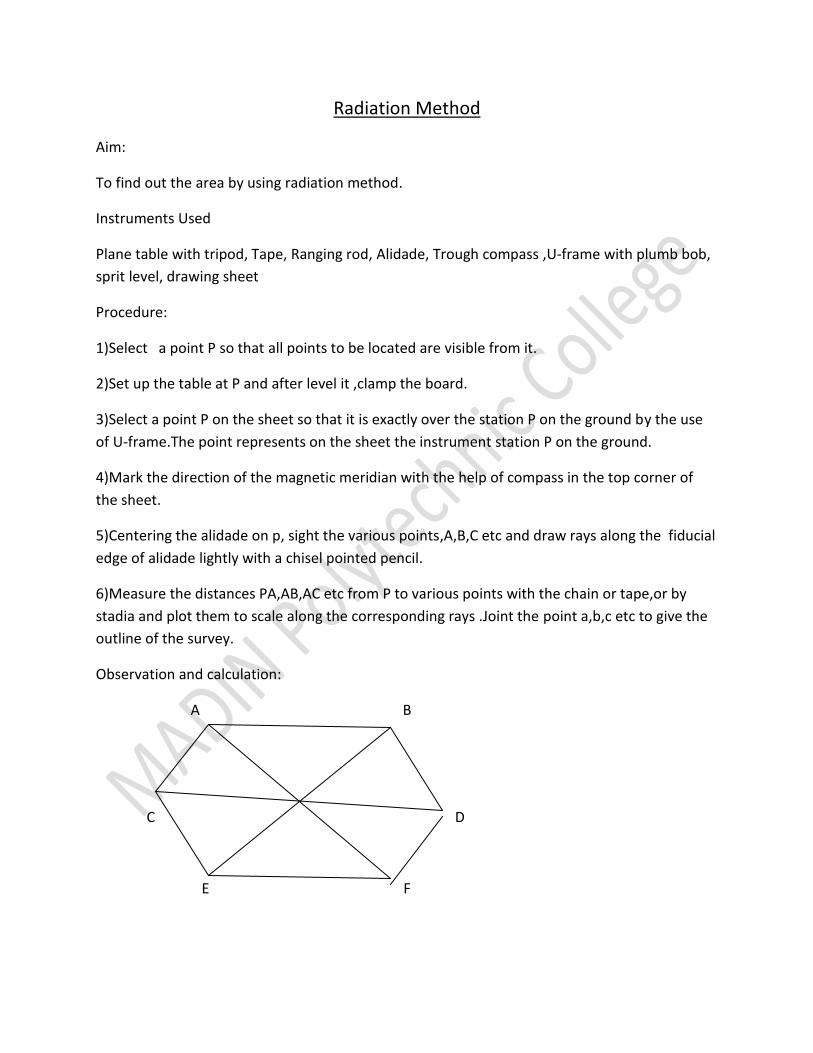
Observation and calculation:
A B
C D
E F

Result:
The total area of the given plot = ………………….. cent
INTERSECTION METHOD
Aim:
To plot the inaccessible distance by intersection method
Instruments Used
Plane table with tripod, Tape, Ranging rod,Alidade,Trough compass,U-frame with plumb
bob,sprit level,drawing sheet
Procedure:
1)Select two points P and Q in a commanding position so that all points to be plotted are visible
from both P and Q.The line joining the station P and Q is known as the base line.
2)With the tablesetup and level at p ,Select a suitable point on the paper so that it is over the
instrument station P on the ground,and mark the direction of the magnetic meridian by eans of
the compass.
3)With the alidade pivoted on the point p,sight the station Q and the objects.A,B,C etc to be
located.,and draw rays along the fiducial edge of the alidade towards Q,A,B,C etc.
4)Measure the distance from P and Q.,accurately with the steel tape and set it off to scale
along the ray drawn to Q thus fixing the position of q on the sheet.
5)Shift the table and set it up at Q .Center the table so that the point q is directly above the
point Q on the ground and level it.
6)Place alidade along qp,and after orienting the table by back sighting on P and clamp it.
7)With the alidade touching q,sight the same object and draw rays.The intersection of these
rays with corresponding rays drawn from p and determine the position of objects A,B,C etc on
the sheet.
Result:
The distance between A and B =……………
TWO POINT PROBLEM
AIM:
To find the required stations by using two point problem.
Apparatus Used:
Plane table with tripod ,Spirit level ,trough compass,U-frame with plumb bob,alidade,ranging
rod,peg,tape etc
Procedure:
Let two points Aand B be the plotted positions on the plane.C is the station over which the
table is to be set up and c is its position on the plane which is required to be located .The
solution of the problem requires two instrument stations.The station is obtained as follows.
1)Choose a suitable auxillary point D, so that the angle CAD and CBD aren’t too acute for good
intersection at A and B.
2)Setup the table at D and level it .Orient the table by compass or by judging ab to be parallel to
AB and clamp it.
3)With the alidade touching a,sight A,and draw a ray through a.Similarly ,with the alidade
against b,sight B and draw a ray through through at d1,which approximately represents the
station D and the orientation is approximately.
4)With the alidade centered on d1 ,sight C and draw a ray d1c1 through d1,estimating the
position of c1.
5)Remove the table and set it up at C with c1over c and level it.Orient the table parallel to its
position at D ,by back sighting on D .To do this ,place the alidade along c and d ,rotate the table
until D is bisected,clamp the table .
6)With the alidade against a,sight A and draw a ray through a,Intersect the line c1d1in C1 .With
the alidade through C1, sight B and draw a ray through C1..This ray will pass through b,provide
the initial orientation of the table at D was correct.But since the orientation at D and also at
C,also constituent was only approximate ,the ray C 1 B will not pass through b.Mark the point
of intersection b1 of C 1 B ,and d1b .The point b1 thus represents B.Hence points ad1c1b1
represents ADCB.But since ab is the true representation of AB ,the error in the initial
orientation is equal to the angle b1ab between the lines ab and ab1.To eliminate the error ,the
table must be rotate through this angle.To do this ,
7)Place the alidade along ab1,and fix a ranging rod P at a great distance from the table in the
line ab1 produced.
8)Place the alidade along ab and turn the table until the ranging rod P is bisected.Clamp the
table ,ab is now parallel to AB and the orientation of the table is correct.
9)To find the true position of C ,center the alidade on a and sight A .Draw a ray through
a.Similarly with alidade touching b,sight B,and draw a ray through b.The intersection of these
two rays gives the true position (c) on the plan of the station ( c) occupied.
Result:
The required instrument station C is occupied by using two point problem.
THREE POINT PROBLEM
Aim:
To locating on the plan of instrument station on the ground by means of observations to three
well defined points whose positions have been already plotted on the plan.
Apparatus Used:
Plane table with tripod ,Spirit level ,trough compass,U-frame with plumb bob,alidade,ranging
rod,peg,tape etc
Procedure:
1)Plot a,b,c, as in the ground.
2)The lengte of ab,bc and ac are given.It forms a triangle.
3)The alidade place along CA .
4)The board rotates till the point A is sighted and the board is clamped.
5)Pivot the alidade on aand sight to b and draw a ray .These two ray will meet at a point d .Then
joint bd,and rotate the board till the point B is sighted and draw a backray.
6)This ray will meet at a point on the line bd,this will be the required station.
Result:
Required instrument station c is located.
STUDY OF LEVELLING
Types of leveling instruments:
The varies types of leveling instruments are
1. Dupy level
2. Y(Wye) level
3. Modern tilting level
4. Automatic level
1. Dumpy level
In dumpy level the telescope rigidly fixed to its support.the main bubble tube and cross bubble
tubes are attached to the top of the telescope.the telescope can be rotated in the horizontal
plane . A foccusing screw provided the telescope enables to bring the image formed by the
objective.The object glass is provided with a ray shade.The levelling had with athree foot screws
enables accurate levelling of the instrument .The instrument may also be provided with a
prismatic compass for observing the bearing of the survey line
2.WYE LEVEL
In wye level the telescope is carried in two vertical Y supports.The wye leve has an advantage
over the dumpy level that the adjustments can be easily tested
3.TILTING LEVEL
Atitlting level is mainly designed for precises levelling work.it has agvantage that due to the
tilting screws levelling can be done much quicker
4.AUTOMATIC LEVEL
The automatic level also designed as self aliging level,which is a recent development it mainly
differs from other levels.That it is not provided with asprit level .As the levelling instrument
levels automatically
TYPES OF LEVELLING STAFFS:
1. Folding type 4m levelling staff
This is made from selected wall seasoned teak wood highly polished and finished. It is made
of two pieces with a joint assembly. The holding staff is of the detachable type, With a locking
device at the back, The staff is joined together in such way that the staff locked 2m length and
also two pieces may be detached from one another well required to facilitate easy handling and
manipulation with one piece the two portion also be locked together and the pieces become
right and striaght The staff has a brass cap at the bottom
Graduation:
The graduations in staffs are machine divided to 200 of the meters, a division equal to 5mm,so
that each part equal to 0.1m is further divided into 20 equal parts by back and white strips so
that 2o of 0.1m work out to .005mm or .5mm
2. Telescope with levelling staff
This is the most common type of levelling staff is used mand is made up of three pieces. The
least count of such levelling staffis 5mmor0.005m.The length of the bottom piece is
1.5m,middle and top piece length is 1.25m.The total length is 4m
3. Aluminium telescopic staff
The is made of special aluminium alloy. It has specialy designed easy locking system pressing
the push bottom .it is very easy to carry
4. Holding of staff
The levelling staff should be fully extended and held verticsly when the reading taken is not
held vertical the reading obtained will be greater then the true reading
COMPONENT PARTS OF LEVELLING INSTRUMENTS:
A levelling instrument essential consits of the following
a. A levelling head with three foot screws which enables to bring the bubble center
b. A telescope that provides line of sight to bisect the distat object
c.A bubble tube to make line of sight horizontal
d.A troipod for supporting the levelling instrument
The telescope of levelling instrument consist of the following
1.A body of the telescope with foccusing arrangement
2.Object lens or objective
3.Eye piece
4.Diaphram
5.The body of telescope and foccusing arrangement vary with the type of Telescope may be
internal or external foccusing type:
External foccusing type
In this case the body consists of two tubes on sliding with in the other the length of the
telescope attern during foccusing,thus effecting the balance of telescope and leading to
displacement of bubble
Internal foccusing type
In internal foccusing telescope the object lens and eyepiece are fixed in position ,the additional
concave lensinside the short tube can be moved between objective lens and diaphram ,the
lenght of the telescope does not after during foccusing and there is no possibility of
displacement of the bubble
1.Object lens
A combination of double convex lens at the front face and a concave lens at the back face is
used. The image formed by the above compound lens is an inverted image
2.Eye piece
The main purpose of eyepiece is to effect the magnification of cross hair of the diaphram, and
the image is formed by the object lens
3.Diaphram
It consists of very fine cross hairs bounded in a brassing fitted inside the bodty of the telescope
.The cross hairs are made of line platinum wires or line atached on glass plate
SIMPLE LEVELLING
Aim :
To determine reduced level of given points by using collimation method
Apparatus Required:
Dumpy level and Levelling staff
Principle:
Height of collimation=Reduced level of bench mark+back sight reading
Reduced level=Height of collimation -intermediate sight/Fore sight
Procedure:
The dumpy level was set up at a point from which all stations A,B,C,D and E were visible.Then
the approximate levelling was done by adjusting the foot screws.A(BS) was taken on bench
mark A reduced level 50.000then the intermediate sights were taken at all sttions b,c,d and
then a fore sight was taken on E then the reduced level at each station were found out by
height of collimation method then check
B.S-F.F=Last R.L-First R.L
Result:
Reduced level of given points wera found by using height of collimation method
DIFFERENTIAL LEVELLING-I
Aim:
To determine the required level of given points A,B,C,D,E and F ,Height collimation method
Apparatus Required:
Dumpy level,Tripod and Levelling staff
Principle:
Height of collimation=Reduced level of bench mark+back sight reading
Reduced level=Height of collimation -intermediate sight/Fore sight
Procedure:
The levelling instrument was placed on the tripod of a convient distance from the station
points A,B,C,D,E and F .A(BS) was taken on bench mark A reduced level 100.000 then the
intermediate sights were taken at all stations B,C,D,E and then a fore sight was taken on F,Then
the instrument was shifted to and levelled at a convient distance from the point E and fore sight
was taken to the last point F
Result:
Reduced level of given points wera found by using height of collimation method
DIFFERENTIAL LEVELLING-II
Aim:
To determine the required level of given points A,B,C, and D ,Rise and fall method
Apparatus Required:
Dumpy level,Tripod and Levelling staff
Principle:
Reduced level=Bench mark+-Rise and fall
staff reading indicates rise or fall according to the reading is smaller or greater the preceding
level
Procedure:
The levelling instrument was placed on the tripod of a convient distance from the station
points A,B,C and D .A(BS) was taken on bench mark A reduced level 100.000 then the
intermediate sights were taken at all stations B,C,D,E and The point A bench mark of reduced
level 50.000.points A and B were intervisible so the instrument was set midway between them
and back sight was taken on A and fore sight was taken on B.Then the instrument was shifted to
new instrument station in such way that B and C were interfore sight was taken to C.The
procedure was repeated for all pod visible.Back sight was taken to the B an
Result:
Reduced level of given points wera found by using height of collimation method
FLY LEVELLING-II
Aim:
To determine the level difference between given station points
Apparatus Required:
Dumpy level,Tripod and Levelling staff
Principle:
Reduced level=Bench mark+-Rise and fall
staff reading indicates rise or fall according to the reading is smaller or greater the preceding
level
Procedure:
The levelling instrument was placed on the tripod and levelled accurately, the station points
A,B and C .The levelling instrument was placed at a convient distance from the station point C
and B,A back sight was taken on C and fore sight was taken on B.The points A and B were not
intervisible in a single set up.the intervisible point A' was taken at a convienient distance from A
and B.The instruments placed between B and A',A back sight was taken to B and for sight was
taken to A',then instrument shifted to a convienient distance from A' and A,A back sight to
A'and fore sight to A was taken
Result:
Level difference between A and B=
Level difference between B and C=
Level difference between C and A=
PROFILE LEVELLING
Aim:
To conduct profile levelling and plot it
Apparatus Required:
Dumpy level,Chain,Tape,Pegs,Cross staff,Ranging rods and flags
Procedure:
First of all a chain was streched through the center of rode points marked at an interwell of 3m
.one point was marked on either sides of the points on center line.the levelling instrument was
setup from which all points are visible A back sight was taken on the bench mark after levelled
the instrument the height of collimation was calculated .Then sights were taken to the of
collimation was calculated .then sights were taken to the points which were marked previously
(points on center line of rode in 3m interwell,one point to right and one point to left at 15m
distance in each 3m chainage)the last point was marked as fore sight,the distance was marked
on distance coloumn as left ,right and center line points and corresponding sight reading were
marked,the reduced level of each points was calculated
Result:
The RL of the points are……………………….
CONTOUR LEVELLING
Aim:
To prepare contour map
Apparatus Required:
Dumpy level with tripod,Alidade,Sprit level,U-frame with plumb bob,Tape,Trough
compass,Drawing sheet,Levelling staff
Procedure:
Plane table was setup at a convienient station(o),Draw radial lines towards the boundary of the
area (ie A,B,C,D and E)by pivoting the alidade at O CHAIN WAS STRECHed to A,marked the
interwells along the radial lines ,placed the levelling instrument at a convienient station such
way that all points wera visible from it,then the levels of various points were founded,marked
the points with same reduced level and interpolated ,then the contour map were plotted
Result:
The contour map prepared.
RECIPROCAL LEVELLING
Aim:
To find the level difference between points
Apparatus Required:
Dumpy level with tripod.Levelling staff,Ranging rod
Principle:
When there is a difficulty in setting the instrument between the points ,we use reciprocal
levelling for finding the level difference between the points
equation
where ha,hb,h'a,h'b are the staff reading
Procedure:
A and B wer the two points ,set up the levelling instrument close to A .a back sight was taken on
A (ha) by looking through the object vane,and a fore sight waa taken on B(hb).then the
instrument was shifted to a new station close to B .Then repeated the process same as at A
.and founded h'a.h'b.the differnce between h'a and h'b and ha and hb was calculated .then the
level difference were calculated by using the formula
Result:
Level differnce between A and B were calculated A is --- higher than B