Embed Size (px)
Citation preview

7/27/2019 Surveys and Ham
http://slidepdf.com/reader/full/surveys-and-ham 1/6
Repeater Site Survey
Site: Sandhamn
System: GSM900

7/27/2019 Surveys and Ham
http://slidepdf.com/reader/full/surveys-and-ham 2/6
Allgon Repeater System Equipment Rev A
Allgon Confidential Proprietary Information. Subject to change without notice.
1.0 Scope
The site is an island called Sandhamn (Sand Harbor). The island is very famous for
it’s marine harbor and is crowded with tourists and boaters during the summer
months. The entire population of the island is about 60, which means during the
winter months the amount of traffic is extremely low.
A repeater site seemed to be a feasible solution considering the financial aspect for a
BTS and the low traffic period during 6 months of wintertime.
The scope was to cover the marine harbor and the surrounding area.
2.0 Site description
The island is quite flat but unfortuantely the marine habor is located behind a hilly,
forest terrain, which causes a shadowed area. The BTS located on the mainland is
situated so that it is not in the line of sight of the marine harbor.
The island has a marine rescue radio communication center located on the hightest
point on the island, which has a suitable tower for their antennas. This tower could
also be used for the repeater site. The tower is located in such a way that the donor
antenna and the mobile antenna could be placed back to back 180°
Fig 1. The tower with bo th antennas
7/27/2019 Surveys and Ham
http://slidepdf.com/reader/full/surveys-and-ham 3/6
Allgon Repeater System Equipment Rev A
Allgon Confidential Proprietary Information. Subject to change without notice.
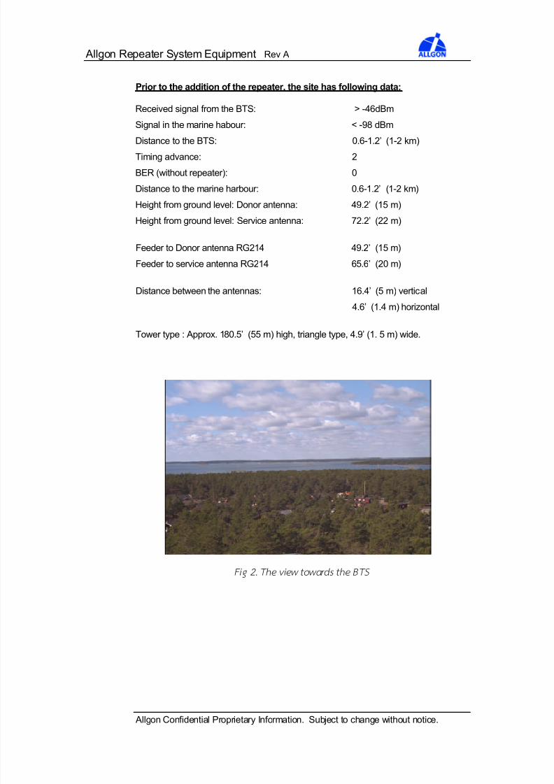
Prior to the addition of the repeater, the site has following data:
Received signal from the BTS: > -46dBm
Signal in the marine habour: < -98 dBm
Distance to the BTS: 0.6-1.2’ (1-2 km)
Timing advance: 2
BER (without repeater): 0
Distance to the marine harbour: 0.6-1.2’ (1-2 km)
Height from ground level: Donor antenna: 49.2’ (15 m)
Height from ground level: Service antenna: 72.2’ (22 m)
Feeder to Donor antenna RG214 49.2’ (15 m)
Feeder to service antenna RG214 65.6’ (20 m)
Distance between the antennas: 16.4’ (5 m) vertical
4.6’ (1.4 m) horizontal
Tower type : Approx. 180.5’ (55 m) high, triangle type, 4.9’ (1. 5 m) wide.
Fig 2. The view towards the BTS
7/27/2019 Surveys and Ham
http://slidepdf.com/reader/full/surveys-and-ham 4/6
Allgon Repeater System Equipment Rev A
Allgon Confidential Proprietary Information. Subject to change without notice.
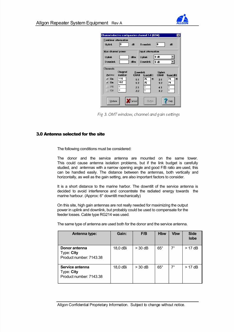
Fig 3. OMT window , channel and g ain settings
3.0 Antenna selected for the site
The following conditions must be considered:
The donor and the service antenna are mounted on the same tower.
This could cause antenna isolation problems, but if the link budget is carefully
studied, and antennas with a narrow opening angle and good F/B ratio are used, this
can be handled easily. The distance between the antennas, both vertically and
horizontally, as well as the gain setting, are also important factors to consider.
It is a short distance to the marine harbor. The downtilt of the service antenna is
decided to avoid interference and concentrate the radiated energy towards the
marine harbour. (Approx: 6° downtilt mechanically)
On this site, high gain antennas are not really needed for maximizing the output
power in uplink and downlink, but probably could be used to compensate for the
feeder losses. Cable type RG214 was used.
The same type of antenna are used both for the donor and the service antenna.
Antenna type: Gain: F/B Hbw Vbw Sidelobe
Donor antenna
Type: City
Product number: 7143.38
18,0 dBi > 30 dB 65° 7° > 17 dB
Service antenna
Type: City
Product number: 7143.38
18,0 dBi > 30 dB 65° 7° > 17 dB
7/27/2019 Surveys and Ham
http://slidepdf.com/reader/full/surveys-and-ham 5/6
Allgon Repeater System Equipment Rev A
Allgon Confidential Proprietary Information. Subject to change without notice.
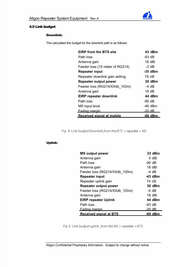
4.0 Link budget
Downlink:
The calculated link budget for the downlink path is as follows:
EIRP from the BTS site 43 dBm
Path loss -93 dB
Antenna gain 18 dBi
Feeder loss (15 meter of RG214) -3 dB
Repeater input -35 dBm
Repeater downlink gain setting 76 dB
Repeater output power 30 dBm
Feeder loss (RG214/XXdb_100m) -4 dB
Antenna gain 18 dB
EIRP repeater downlink 44 dBm
Path loss -90 dB
MS input level -46 dBm
Fading margin -20 dB
Received signal at mobile -66 dBm
Fig. 4. Link bu dget Down link from the BTS > repeater > MS
Uplink:
Fig 5. Link budg et uplink from the MS > repeater > BTS
MS output power 33 dBm
Antenna gain 0 dBi
Path loss -90 dB
Antenna gain 18 dBi
Feeder loss (RG214/XXdb_100m) -4 dB
Repeater input -43 dBm
Repeater uplink gain 74 dB
Repeater output power 30 dBmFeeder loss (RG214/XXdb_100m) -4 dB
Antenna gain 18 dBi
EIRP repeater Uplink 44 dBm
Path loss -93 dB
Fading margin -20 dB
Received signal at BTS -69 dBm
7/27/2019 Surveys and Ham
http://slidepdf.com/reader/full/surveys-and-ham 6/6
Allgon Repeater System Equipment Rev A
Allgon Confidential Proprietary Information. Subject to change without notice.
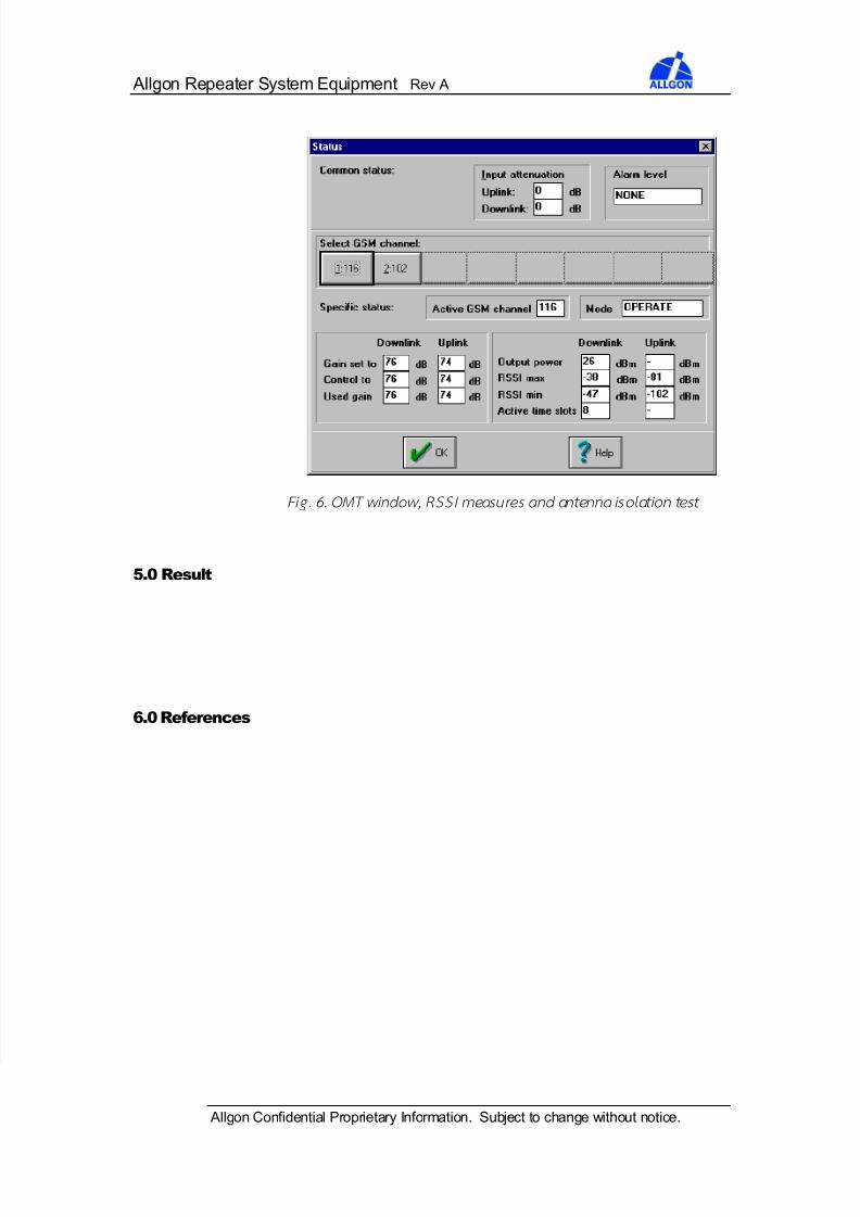
Fig. 6. OMT window , RSSI measures and antenna iso lation test
5.0 Result
6.0 References