Embed Size (px)
Citation preview
Alaska Resources Library & Information Services
Susitna-Watana Hydroelectric Project Document ARLIS Uniform Cover Page
Title:
SuWa 280 Susitna-Watana Hydroelectric Project engineering feasibility report. [Main report] Author(s) – Personal:
Author(s) – Corporate: MWH Americas, Inc. AEA-identified category, if specified: Engineering feasibility report AEA-identified series, if specified: Series (ARLIS-assigned report number): Existing numbers on document:
Susitna-Watana Hydroelectric Project document number 280 13-1421-REP-073114 Report 14-21-REP v0.0 AEA11-022 Published by: Date published:
[Anchorage, Alaska : Alaska Energy Authority, 2014] December 2014 Published for: Date or date range of report: Prepared for Alaska Energy Authority
Volume and/or Part numbers:
Final or Draft status, as indicated: Table of contents, executive summary, sections 1-17 Document type: Pagination:
731 pages in various paginations (main report)
Full report is 2303 pages in various paginations plus 3 plates.
Related work(s): Pages added/changed by ARLIS: Appendix B (SuWa 281-284).
Notes: Three appendices were not released. "Appendix A : Drawings" (listed on pages xxvii to xxxii in the table of contents) is not available. Appendices B1 and B7 are not available. A placeholder page was issued for B1.
A flash drive containing a visualization of all 3-D models accompanies the report and is called "Visualization Susitna-Watana Animation Draft" (see page 25 of Section 1). This flash drive was not received by ARLIS (Alaska Resources Library and Information Services.
All reports in the Susitna-Watana Hydroelectric Project Document series include an ARLIS-produced cover page and an ARLIS-assigned number for uniformity and citability. All reports are posted online at http://www.arlis.org/resources/susitna-watana/
Report
14-21-REP v0.0
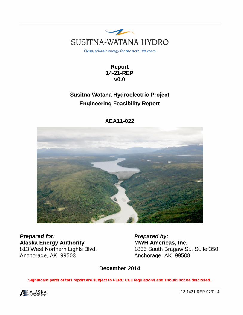
Susitna-Watana Hydroelectric Project
Engineering Feasibility Report
AEA11-022
Prepared for: Prepared by: Alaska Energy Authority MWH Americas, Inc. 813 West Northern Lights Blvd. 1835 South Bragaw St., Suite 350 Anchorage, AK 99503 Anchorage, AK 99508
December 2014
Significant parts of this report are subject to FERC CEII regulations and should not be disclosed.
13-1421-REP-073114

PREFACE
This report has been prepared in accordance with the terms set out in Contract No. AEA-11-022 between the Alaska Energy Authority (AEA) and MWH Americas Inc. (MWH), under task order authorization designated as NTP 13 – Engineering Feasibility Studies. Neither MWH, nor AEA, nor any person acting on any of their behalf, make any warranty, express or implied, or assume any liability with respect to the use of any information, method, or statement contained in this report.
Any recipient of this report, including AEA, any prospective lenders, contractors, or any other stakeholder, by their receipt and use of this report, hereby releases MWH and AEA from any liability for direct, indirect, or consequential loss or damage, whether arising in contract, tort (including negligence), strict liability, or otherwise.
MWH was neither requested to perform, nor has performed, environmental site assessments in connection with the proposed facilities described in this report. Also, MWH was neither requested to, nor has performed, any economic analyses or detailed evaluation of any permits or license requirements other than what is required by the Federal Energy Regulatory Commission (FERC) for a license application.
This report has been prepared for the exclusive use of AEA. Any third party use of the report, or any reliance on or decisions made on the basis of this report will be the responsibility of such third party. This report must be read in its entirety; MWH will not be liable for reliance on excerpts or portions of this report in the abstract.
The content of this report is governed by confidentiality clauses in the contract between MWH and AEA. The contents of this document may not be disclosed to other parties in a manner not consistent with the terms of the confidentiality clauses of that contract.
Some information contained herein is subject to FERC Critical Energy Infrastructure Information (CEII) Regulations and required non-disclosure documentation.


LIST OF PREPARERS
MWH Americas, Inc. Brian Sadden – Project Manager
Michael Bruen – Geology and Geotechnical Exploration
Don Crone – Cost Estimating Specialist
Andrew Frisk – CAD
Kirby Gilbert – FERC Licensing Specialist
John Haapala – Hydrology and Power Operations Engineer
Aled Hughes – Lead Dam Engineer
Dina Hunt – Seismicity Specialist
Farrokh Javanmardi – Finite Element Analysis
Joseph Kovacich - Geotechnical
Julie Stanaszek – Civil Engineer Lead
Sub Consultants Applied Weather Associates – Edward Tomlinson
Electric Power Systems Inc. – David Burlingame
Fugro Consultants, Inc. – Justin Pearce
Golder Associates, Inc. – Robert Dugan
Hanson Alaska, LLC – Michael Pochop
Norm Abrahamson – Independent Consultant, Seismicity
Slater Consulting – Kenneth Slater
Tom Lovas – Energy & Resource Economics
Senior Technical Reviewers MWH – Peter Dickson – Geotechnical
MWH – Peter Donalek – Transmission
MWH – Howard Lee – Hydropower
MWH – Jose Mayen – Electrical
MWH – Glenn Tarbox – Dams
Nuss Engineering, LLC – Larry Nuss – Finite Element Modelling

ALASKA ENERGY AUTHORITY AEA11-022
ENGINEERING FEASIBILITY REPORT
TABLE OF CONTENTS
EXECUTIVE SUMMARY .......................................................................................................ES-1
1. INTRODUCTION ........................................................................................................... 1-1
1.1. Background .......................................................................................................... 1-1
1.2. Summary of Previous Studies .............................................................................. 1-6
1.3. Scope of Current Engineering Work .................................................................... 1-7
1.4. Overview of FERC Licensing Process ................................................................ 1-9
1.5. Status of Environmental Study Program............................................................ 1-11
1.6. Project Description............................................................................................. 1-15
1.6.1. General ............................................................................................. 1-15
1.6.2. Watana Dam and Reservoir ............................................................. 1-16
1.6.3. Powerhouse ...................................................................................... 1-19
1.6.4. Ancillary Facilities ........................................................................... 1-20
1.6.5. Transportation Access ...................................................................... 1-20
1.6.6. Electric Transmission and Interconnection Facilities ...................... 1-22
1.6.7. Project Operations ............................................................................ 1-23
1.6.8. Construction Schedule ..................................................................... 1-24
1.7. Visualization ...................................................................................................... 1-25
1.8. Principal Project Parameters .............................................................................. 1-25
1.9. Board of Consultants Review ............................................................................ 1-30
2. SCOPE OF WORK .......................................................................................................... 2-1
2.1. Evolution of Plan of Study ................................................................................... 2-1
2.2. Hydrology ............................................................................................................ 2-1
2.3. Power Studies....................................................................................................... 2-2
2.4. Geotechnical Exploration and Characterization .................................................. 2-2
2.5. Seismic Studies .................................................................................................... 2-3 2.6. Development of Layout and Design .................................................................... 2-3
2.7. Access .................................................................................................................. 2-4
2.8. Transmission ........................................................................................................ 2-4
Susitna-Watana Hydroelectric Project Alaska Energy Authority FERC Project No. 14241 Page i December 2014
ALASKA ENERGY AUTHORITY AEA11-022
ENGINEERING FEASIBILITY REPORT
2.9. Surveys ................................................................................................................. 2-4
2.10. Site Facilities ........................................................................................................ 2-5
2.11. Construction Cost Estimates and Schedules ........................................................ 2-5
3. PREVIOUS STUDIES..................................................................................................... 3-1
3.1. Early Studies of Hydroelectric Potential.............................................................. 3-1
3.2. U.S. Bureau of Reclamation – 1953 Study .......................................................... 3-2
3.3. U.S. Bureau of Reclamation – 1961 Study .......................................................... 3-2
3.4. Alaska Power Administration – 1974 .................................................................. 3-3
3.5. Kaiser Proposal for Development – 1974 ............................................................ 3-3
3.6. U.S. Army Corps of Engineers – 1975 and 1979 Studies .................................... 3-4
3.7. Alaska Power Authority – Acres / Harza / Ebasco 1980s ................................... 3-4
3.8. Alaska Energy Authority – 2009-2010 ................................................................ 3-6
4. RAILBELT LOAD FORECASTS .................................................................................. 4-1
4.1. Regional Generation Facilities ............................................................................. 4-1
4.2. Regional Transmission Facilities ......................................................................... 4-2
4.3. Regional Electrical Load Requirements .............................................................. 4-3
5. INTEGRATION INTO THE RAILBELT SYSTEM ...................................................... 5-1
5.1. Electric System Studies........................................................................................ 5-1
5.2. Transmission Study Improvements Pre-Watana .................................................. 5-1
5.3. Study Criteria ....................................................................................................... 5-2
5.4. System Study Methodology ................................................................................. 5-2
5.5. Results .................................................................................................................. 5-4
5.6. Future Studies ...................................................................................................... 5-5
5.7. Project Operation and Resource Integration ........................................................ 5-6
5.7.1. Basis of Studies .................................................................................. 5-6
5.7.2. Plant and System Operation Requirements ........................................ 5-8
5.7.3. General Power Plant and Railbelt System Criteria ............................ 5-9
5.7.4. Operating Security Criteria ................................................................ 5-9
5.7.5. Plant Operation and Maintenance .................................................... 5-10
5.7.6. Economic Operation ........................................................................ 5-11
5.7.7. Modeling Exercise and Results ........................................................ 5-11
Susitna-Watana Hydroelectric Project Alaska Energy Authority FERC Project No. 14241 Page ii December 2014
ALASKA ENERGY AUTHORITY AEA11-022
ENGINEERING FEASIBILITY REPORT
5.7.8. 2013 Modeling and Analysis ........................................................... 5-15
5.7.9. Forecast Data and Results for 2013 Analyses.................................. 5-17
5.7.10. Updated Analysis 2014 .................................................................... 5-21
6. SUSITNA BASIN AND DAM SITE CHARACTERISTICS ......................................... 6-1
6.1. Climatology.......................................................................................................... 6-1
6.2. Hydrology ............................................................................................................ 6-4
6.2.1. Hydrologic Record ............................................................................. 6-4
6.2.2. Monthly Flow Frequency and Flow Duration ................................... 6-8
6.2.3. Watana Dam Site Historical Inflows ............................................... 6-14
6.2.4. Flood Frequency .............................................................................. 6-18
6.2.5. Probable Maximum Precipitation / Probable Maximum Flood ....... 6-23
6.2.6. Susitna Watershed Flow Distribution .............................................. 6-23
6.2.7. Hydrologic Change .......................................................................... 6-25
6.3. Geology .............................................................................................................. 6-28
6.3.1. Sources of Information .................................................................... 6-28
6.3.2. Regional Geologic Setting ............................................................... 6-42
6.3.3. Seismic Hazard ................................................................................ 6-61
6.3.4. Site Geology..................................................................................... 6-71
6.3.5. Dam Site Area Fault Rupture Evaluation ...................................... 6-104
6.3.6. Reservoir Geology ......................................................................... 6-115
7. SELECTION OF WATANA GENERAL ARRANGEMENT........................................ 7-1
7.1. Site Topography ................................................................................................... 7-1
7.2. Environmental Considerations ............................................................................. 7-2
7.3. Selection of Reservoir Levels .............................................................................. 7-4
7.4. Selection of the Inflow Design Flood .................................................................. 7-6
7.5. Selection of Installed Capacity ............................................................................ 7-6
7.5.1. Introduction ........................................................................................ 7-6
7.5.2. Future Railbelt Electrical System Reliability / Redundancy Requirements ..................................................................................... 7-8
7.5.3. Selection of Powerhouse Total Installed Capacity ............................ 7-9
7.5.4. Generating Unit Selection and Capacity .......................................... 7-15
Susitna-Watana Hydroelectric Project Alaska Energy Authority FERC Project No. 14241 Page iii December 2014
ALASKA ENERGY AUTHORITY AEA11-022
ENGINEERING FEASIBILITY REPORT
7.5.5. Discussion and Selected Configuration ........................................... 7-23
7.6. Project Configuration Evaluation ...................................................................... 7-25
7.6.1. Dam .................................................................................................. 7-25
7.6.2. Diversion .......................................................................................... 7-28
7.6.3. Spillway ........................................................................................... 7-29
7.6.4. Power Facilities ................................................................................ 7-29
7.6.5. Summary of Comparison and Selection of RCC ............................. 7-30
8. SITE ACCESS PLAN...................................................................................................... 8-1
Background .......................................................................................................... 8-1 8.1.
Objectives ............................................................................................................ 8-2 8.2.
Approach .............................................................................................................. 8-2 8.3.
Corridor Selection and Evaluation ....................................................................... 8-2 8.4.
Description of Basic Plans ................................................................. 8-4 8.4.1.
Evaluation ............................................................................................................ 8-7 8.5.
Evolution of Access Plans ................................................................................. 8-11 8.6.
Access Plan for Estimate ................................................................................... 8-13 8.7.
Bridge at Site...................................................................................................... 8-13 8.8.
Railhead ............................................................................................................. 8-14 8.9.
Previous Studies and Site Selection ................................................. 8-14 8.9.1.
Transportation Methods ................................................................... 8-14 8.9.2.
Railway Cars .................................................................................... 8-15 8.9.3.
Transloading Facility – Cantwell Site.............................................. 8-16 8.9.4.
Railway Construction....................................................................... 8-16 8.9.5.
Gold Creek Site Alternative ............................................................. 8-17 8.9.6.
Chulitna Site Alternative.................................................................. 8-17 8.9.7.
Necessary Modifications to the Railroad ......................................... 8-17 8.9.8.
Other Potential Facilities.................................................................. 8-18 8.9.9.
Airstrip ............................................................................................................... 8-19 8.10.
Previous Siting ................................................................................. 8-19 8.10.1.
Airstrip Criteria ................................................................................ 8-19 8.10.2.
Selected Airport ............................................................................... 8-20 8.10.3.
Susitna-Watana Hydroelectric Project Alaska Energy Authority FERC Project No. 14241 Page iv December 2014
ALASKA ENERGY AUTHORITY AEA11-022
ENGINEERING FEASIBILITY REPORT
Runway Length and Width .............................................................. 8-21 8.10.4.
Approaches ...................................................................................... 8-21 8.10.5.
Runway Ends and Aprons ................................................................ 8-22 8.10.6.
Aircraft Operational Aids ................................................................ 8-23 8.10.7.
Facilities ........................................................................................... 8-23 8.10.8.
Summary .......................................................................................... 8-24 8.10.9.
Unconventional Access ...................................................................................... 8-24 8.11.
Hoverbarge ....................................................................................... 8-25 8.11.1.
CAT Trains ...................................................................................... 8-25 8.11.2.
Air Transport of Heavy Equipment ................................................. 8-25 8.11.3.
9. PROBABLE MAXIMUM PRECIPITATION AND PROBABLE MAXIMUM FLOOD ............................................................................................................................ 9-1
9.1. Introduction .......................................................................................................... 9-1
9.2. Watershed Description ......................................................................................... 9-1
9.3. Historic Floods ..................................................................................................... 9-2
9.4. Hydrologic Model ................................................................................................ 9-3
9.5. Probable Maximum Precipitation ........................................................................ 9-4
9.6. Snowpack ............................................................................................................. 9-6
9.7. Coincident and Antecedent Conditions ............................................................... 9-9
9.8. Probable Maximum Flood Hydrograph ............................................................... 9-9
10. WATANA DEVELOPMENT DESCRIPTION ............................................................ 10-1
10.1. Introduction ........................................................................................................ 10-1
10.1.1. Site Survey and Mapping ................................................................. 10-1
10.1.2. Project General Arrangement .......................................................... 10-2
10.2. Site Facilities ...................................................................................................... 10-3
10.2.1. Location of Facilities ....................................................................... 10-4
10.2.2. Temporary Construction Camp........................................................ 10-5
10.2.3. Contractor Facilities ......................................................................... 10-7
10.2.4. Permanent Village ............................................................................ 10-7
10.2.5. Owner Offices .................................................................................. 10-8
10.2.6. Operators Accommodation .............................................................. 10-8
Susitna-Watana Hydroelectric Project Alaska Energy Authority FERC Project No. 14241 Page v December 2014
ALASKA ENERGY AUTHORITY AEA11-022
ENGINEERING FEASIBILITY REPORT
10.2.7. Water Supply ................................................................................... 10-9
10.2.8. Wastewater Collection and Treatment ........................................... 10-15
10.2.9. Solid Waste Disposal ..................................................................... 10-18
10.2.10. Fire Protection System ................................................................... 10-20
10.3. Geotechnical Design Considerations ............................................................... 10-21
10.3.1. Engineering Geology ..................................................................... 10-21
10.3.2. Construction Materials Sources ..................................................... 10-42
10.3.3. Design and Construction Considerations ....................................... 10-45
10.3.4. Underground Excavations .............................................................. 10-59
10.3.5. Cofferdams ..................................................................................... 10-61
10.3.6. Watana Relict Channel .................................................................. 10-62
10.4. River Diversion ................................................................................................ 10-63
10.4.1. General ........................................................................................... 10-63
10.4.2. Criteria ........................................................................................... 10-63
10.4.3. Analytical Results .......................................................................... 10-65
10.4.4. Operation of Diversion .................................................................. 10-67
10.5. Dam – Layout Development ............................................................................ 10-69
10.5.1. General Methodology .................................................................... 10-69
10.5.2. Pre-application Document (PAD) Dam (Layout 1) ....................... 10-72
10.5.3. Optimization of Dam Configuration .............................................. 10-72
10.5.4. Curved Alignment Analysis ........................................................... 10-77
10.5.5. Analytical Development ................................................................ 10-79
10.5.6. Preliminary Design Criteria – Structural Analyses ........................ 10-80
10.5.7. Two-Dimensional Gravity Analysis .............................................. 10-81
10.5.8. Finite Element Modeling of Dam .................................................. 10-82
10.6. Dam – Preliminary Analysis ............................................................................ 10-83
10.6.1. Initial Dam Configuration (Layout 2) ............................................ 10-83
10.6.2. Revised Dam Configuration (Layout 3) ........................................ 10-99
10.6.3. 2nd Revised Dam Configuration (Layout 4) ............................... 10-114
10.6.4. Sensitivity to Foundation Conditions........................................... 10-129
10.6.5. Discussion on Analysis without Foundation Mass ...................... 10-130
Susitna-Watana Hydroelectric Project Alaska Energy Authority FERC Project No. 14241 Page vi December 2014
ALASKA ENERGY AUTHORITY AEA11-022
ENGINEERING FEASIBILITY REPORT
10.6.6. Modeling of Fluid Structure Interaction ...................................... 10-133
10.7. Dam – Final Modeling including FSI, Foundation Mass and Damping ........ 10-134
10.7.1. Final Dam Layout (Layout 4 – Modified) ................................... 10-134
10.7.2. LS-DYNA Analysis Software...................................................... 10-134
10.7.3. Selection of Time Histories for Final Modeling .......................... 10-137
10.7.4. Methodology of Structural Analysis ............................................ 10-154
10.7.5. Conclusions .................................................................................. 10-175
10.8. RCC Placement .............................................................................................. 10-177
10.8.1. RCC and Aggregate Quantities / Production ............................... 10-177
10.8.2. RCC Placement Sequencing ........................................................ 10-178
10.9. Dam – Thermal Considerations ..................................................................... 10-186
10.9.1. General ......................................................................................... 10-186
10.9.2. Transverse Joints .......................................................................... 10-186
10.9.3. Abutment Temperature ................................................................ 10-187
10.9.4. Insulation Requirements .............................................................. 10-187
10.9.5. Control of Mixing and Placing Temperatures ............................. 10-188
10.9.6. Preliminary Simplified Thermal Analysis ................................... 10-188
10.10. Instrumentation .............................................................................................. 10-196
10.10.1. General ......................................................................................... 10-196
10.10.2. Dam .............................................................................................. 10-197
10.10.3. Rock Slopes and Abutments ........................................................ 10-200
10.10.4. Relict Channel .............................................................................. 10-201
10.11. Freeboard ....................................................................................................... 10-201
10.11.1. Analysis........................................................................................ 10-201
10.11.2. Wind Speed .................................................................................. 10-202
10.11.3. Wave Run Up and Set Up ............................................................ 10-203
10.12. Spillway ......................................................................................................... 10-210
10.12.1. Radial Gates and Operators ......................................................... 10-214
10.12.2. Spillway Bulkheads ..................................................................... 10-215
10.12.3. Spillway Gantry Crane ................................................................. 10-216
10.13. Emergency Release Facilities ........................................................................ 10-216
Susitna-Watana Hydroelectric Project Alaska Energy Authority FERC Project No. 14241 Page vii December 2014
ALASKA ENERGY AUTHORITY AEA11-022
ENGINEERING FEASIBILITY REPORT
10.14. Outlet Facilities .............................................................................................. 10-218
10.14.1. Intake............................................................................................ 10-218
10.14.2. Intake Gate ................................................................................... 10-219
10.14.3. Intake Bulkheads .......................................................................... 10-219
10.14.4. Intake Trashracks ......................................................................... 10-220
10.14.5. Gantry Crane ................................................................................ 10-220
10.14.6. Pipes and Manifold ...................................................................... 10-220
10.14.7. Discharge Structure ...................................................................... 10-220
10.14.8. Fixed-Cone Discharge Valves ..................................................... 10-221
10.14.9. Butterfly Valves ........................................................................... 10-222
10.14.10. Monorail Hoist ............................................................................. 10-223
10.14.11. Bridge Crane ................................................................................ 10-223
10.14.12. Discharge Area............................................................................. 10-223
10.15. Fish Passage Considerations .......................................................................... 10-223
10.16. Power Intake .................................................................................................. 10-223
10.16.1. Intake Gates and Operators .......................................................... 10-224
10.16.2. Intake Bulkheads .......................................................................... 10-225
10.16.3. Intake Shutters ............................................................................. 10-225
10.16.4. Intake Trashracks ......................................................................... 10-226
10.16.5. Intake Gantry Crane ..................................................................... 10-226
10.17. Penstocks........................................................................................................ 10-227
10.18. Powerhouse .................................................................................................... 10-228
10.18.1. General Arrangement ................................................................... 10-228
10.18.2. Turbine Inlet Valve ...................................................................... 10-229
10.19. Turbines ......................................................................................................... 10-230
10.19.1. Turbine Components .................................................................... 10-231
10.19.2. Governing System ........................................................................ 10-232
10.20. Generators ...................................................................................................... 10-232
10.20.1. General ......................................................................................... 10-232
10.20.2. Configuration and Ratings ........................................................... 10-233
10.20.3. Generator Structure ...................................................................... 10-233
Susitna-Watana Hydroelectric Project Alaska Energy Authority FERC Project No. 14241 Page viii December 2014
ALASKA ENERGY AUTHORITY AEA11-022
ENGINEERING FEASIBILITY REPORT
10.21. Exciter ............................................................................................................ 10-238
10.22. Generator Step-up Transformers.................................................................... 10-238
10.22.1. General ......................................................................................... 10-238
10.22.2. Ratings and Characteristics .......................................................... 10-238
10.22.3. Tank ............................................................................................. 10-239
10.22.4. Base .............................................................................................. 10-239
10.22.5. Core Assembly ............................................................................. 10-239
10.22.6. Winding........................................................................................ 10-240
10.22.7. Bushings ....................................................................................... 10-240
10.22.8. Surge Arresters............................................................................. 10-240
10.22.9. Accessories .................................................................................. 10-240
10.22.10. Oil Preservation System ............................................................... 10-241
10.22.11. Cooling System ............................................................................ 10-241
10.23. Unit Protection and Control System .............................................................. 10-241
10.23.1. General ......................................................................................... 10-241
10.23.2. System Configuration .................................................................. 10-242
10.23.3. Unit Control Panel ....................................................................... 10-243
10.23.4. Control Room Operations ............................................................ 10-244
10.23.5. Unit Protection ............................................................................. 10-245
10.23.6. Station Monitoring ....................................................................... 10-246
10.23.7. Instrumentation Cabinet ............................................................... 10-246
10.23.8. Distributed Input / Output ............................................................ 10-247
10.23.9. HMI Terminals............................................................................. 10-247
10.24. Miscellaneous Mechanical Equipment .......................................................... 10-249
10.24.1. Powerhouse Bridge Crane ............................................................ 10-249
10.24.2. Draft Tube Bulkheads .................................................................. 10-249
10.24.3. Draft Tube Gantry Crane ............................................................. 10-250
10.24.4. Station Drainage System .............................................................. 10-250
10.24.5. Unit Dewatering System .............................................................. 10-250
10.24.6. Station Raw Water System .......................................................... 10-250
10.24.7. Compressed Air System ............................................................... 10-251
Susitna-Watana Hydroelectric Project Alaska Energy Authority FERC Project No. 14241 Page ix December 2014
ALASKA ENERGY AUTHORITY AEA11-022
ENGINEERING FEASIBILITY REPORT
10.24.8. HVAC Systems ............................................................................ 10-251
10.24.9. Standby Generator ....................................................................... 10-251
10.25. Accessory Electrical Equipment .................................................................... 10-251
10.25.1. Powerhouse Alternating Current System ..................................... 10-251
10.25.2. Powerhouse DC System ............................................................... 10-251
10.25.3. Powerhouse Lighting ................................................................... 10-252
10.25.4. Powerhouse Grounding System ................................................... 10-252
10.26. Switchyard Structures and Equipment ........................................................... 10-252
10.26.1. Switchyard Arrangement ............................................................. 10-252
10.26.2. Circuit Breakers ........................................................................... 10-253
10.26.3. Instrument Transformers .............................................................. 10-253
10.26.4. Bus, Overhead Lines and Structures ............................................ 10-253
10.26.5. Grounding .................................................................................... 10-254
10.26.6. Control House .............................................................................. 10-254
10.27. Reservoir ........................................................................................................ 10-255
10.27.1. Reservoir Clearing ....................................................................... 10-255
10.28. Relict Channel Treatment .............................................................................. 10-255
10.28.1. Surface Flows............................................................................... 10-255
10.28.2. Subsurface Flows ......................................................................... 10-256
10.28.3. Permafrost .................................................................................... 10-256
10.28.4. Liquefaction ................................................................................. 10-256
10.28.5. Remedial Work Influence on Construction Schedules ................ 10-257
10.28.6. Relict Channel Treatment ............................................................ 10-257
11. TRANSMISSION AND INTERCONNECTION FACILITIES ................................... 11-1
11.1. Electric System Studies...................................................................................... 11-1
11.1.1. General ............................................................................................. 11-1
11.1.2. Transmission Study Assumptions .................................................... 11-1
11.1.3. Study Criteria ................................................................................... 11-2
11.1.4. System Study Methodology ............................................................. 11-4
11.1.5. Results .............................................................................................. 11-6
11.1.6. Future Studies .................................................................................. 11-9
Susitna-Watana Hydroelectric Project Alaska Energy Authority FERC Project No. 14241 Page x December 2014
ALASKA ENERGY AUTHORITY AEA11-022
ENGINEERING FEASIBILITY REPORT
11.2. Corridor Selection ............................................................................................ 11-10
11.2.1. General ........................................................................................... 11-10
11.2.2. Evaluation Criteria ......................................................................... 11-11
11.2.3. Route Alternatives ......................................................................... 11-12
11.3. Towers, Foundations and Conductors.............................................................. 11-13
11.4. Interconnections ............................................................................................... 11-13
11.4.1. Substation Costs ............................................................................. 11-14
11.4.2. BESS Costs .................................................................................... 11-14
11.5. Comparative Costs ........................................................................................... 11-17
12. PROJECT OPERATION AND RESOURCE UTILIZATION ..................................... 12-1
12.1. Proposed Project Operation ............................................................................... 12-2
12.1.1. Background ...................................................................................... 12-2
12.1.2. Environmental Flows ....................................................................... 12-3
12.1.3. Reservoir Operation ......................................................................... 12-4
12.1.4. Operating Scenario......................................................................... 12-10
12.2. Project Generation ........................................................................................... 12-18
12.3. Downstream River Flows and Depths ............................................................. 12-22
13. CONSTRUCTION METHODOLOGY AND ESTIMATES OF COST....................... 13-1
13.1. General ............................................................................................................... 13-1
13.2. Estimating Methodology – Construction ........................................................... 13-5
13.2.1. Basis of Pricing ................................................................................ 13-5
13.2.2. Estimate Classification..................................................................... 13-5
13.2.3. Estimating / Scheduling Methodology or System ........................... 13-7
13.2.4. Estimating Accuracy and Contingency ............................................ 13-8
13.2.5. Quantities ......................................................................................... 13-8
13.2.6. Significant Assumptions .................................................................. 13-9
13.2.7. Direct Cost Development ................................................................. 13-9
13.2.8. Indirect Costs ................................................................................. 13-10
13.2.9. Estimate Add-Ons .......................................................................... 13-10
13.2.10. Labor Rate ...................................................................................... 13-10
13.2.11. Equipment Rate .............................................................................. 13-10
Susitna-Watana Hydroelectric Project Alaska Energy Authority FERC Project No. 14241 Page xi December 2014
ALASKA ENERGY AUTHORITY AEA11-022
ENGINEERING FEASIBILITY REPORT
13.2.12. Escalation ....................................................................................... 13-11
13.2.13. Allowances and Contingency ........................................................ 13-11
13.2.14. Market Conditions ......................................................................... 13-11
13.2.15. Construction and Contracting Aspects........................................... 13-11
13.3. Assumed Construction Methodology .............................................................. 13-13
13.3.1. General ........................................................................................... 13-13
13.3.2. Main Access Road ......................................................................... 13-14
13.3.3. Railroad Offloading Facility .......................................................... 13-18
13.3.4. Camp and Airstrip Civil Works ..................................................... 13-20
13.3.5. Supply and Erect Camp ................................................................. 13-23
13.3.6. Main Civil Works Construction ..................................................... 13-25
13.3.7. Turbine and Generator Supply Contract ........................................ 13-32
13.3.8. Transmission Line and Interconnection ......................................... 13-35
13.3.9. Site and Reservoir Clearing ........................................................... 13-37
13.3.10. Air Transport Services ................................................................... 13-39
13.3.11. Railroad Operations ....................................................................... 13-41
13.3.12. Camp Operation ............................................................................. 13-44
13.3.13. Medical Services ............................................................................ 13-46
13.3.14. Service Contracts – Manpower ...................................................... 13-46
13.3.15. Construction Manpower – All Contracts ....................................... 13-47
13.3.16. Logistics ......................................................................................... 13-48
13.4. Construction Cost Estimate Derivation ........................................................... 13-50
13.4.1. First Read of Estimate .................................................................... 13-52
13.4.2. Second Read of Estimate ............................................................... 13-53
13.4.3. Final Draft Construction Cost Estimate ......................................... 13-55
13.5. Non Construction Costs ................................................................................... 13-56
13.5.1. General ........................................................................................... 13-56
13.5.2. Cost Items ...................................................................................... 13-57
13.5.3. Derivation of Non-Construction Costs .......................................... 13-57
13.6. Total Project Cost Estimate ............................................................................. 13-60
13.7. Cashflow .......................................................................................................... 13-60
Susitna-Watana Hydroelectric Project Alaska Energy Authority FERC Project No. 14241 Page xii December 2014
ALASKA ENERGY AUTHORITY AEA11-022
ENGINEERING FEASIBILITY REPORT
13.8. Cost Variability Analysis ................................................................................. 13-61
13.9. Risk Analysis ................................................................................................... 13-65
13.10. Operation and Maintenance Plan and Budget .................................................. 13-65
13.10.1. Operation and Maintenance Plan ................................................... 13-66
13.10.2. Site Staffing ................................................................................... 13-67
13.10.3. Power Dispatch Arrangements and Staffing .................................. 13-67
13.10.4. Annual Operation and Maintenance Budget .................................. 13-68
13.10.5. Annual General and Administrative Budget .................................. 13-68
13.10.6. Environmental Monitoring and Compliance ................................. 13-69
13.10.7. Special Considerations in the Early Years ..................................... 13-69
14. ENGINEERING AND CONSTRUCTION SCHEDULES ........................................... 14-1
14.1. Preparation of Schedules.................................................................................... 14-1
14.1.1. Calendar ........................................................................................... 14-2
14.1.2. Constraints ....................................................................................... 14-3
14.1.3. Individual Contract Schedules ......................................................... 14-3
14.2. Construction Schedule Derivation ................................................................... 14-13
14.2.1. General ........................................................................................... 14-13
14.2.2. Potential Early Works .................................................................... 14-14
14.2.3. Schedule Notes............................................................................... 14-15
15. CONCLUSIONS AND RECOMMENDATIONS ........................................................ 15-1
15.1. Conclusions ........................................................................................................ 15-1
15.1.1. Technical Feasibility ........................................................................ 15-1
15.1.2. Economic Feasibility ....................................................................... 15-5
15.1.3. Environmental Considerations ......................................................... 15-6
15.2. Recommendations .............................................................................................. 15-7
15.2.1. Funding ............................................................................................ 15-7
15.2.2. Geotechnical .................................................................................... 15-7
15.2.3. Engineering ...................................................................................... 15-7
15.2.4. Procurement Plan ............................................................................. 15-7
15.2.5. Integrated System Studies ................................................................ 15-7
15.2.6. Centralized Dispatch Planning ......................................................... 15-8
Susitna-Watana Hydroelectric Project Alaska Energy Authority FERC Project No. 14241 Page xiii December 2014
ALASKA ENERGY AUTHORITY AEA11-022
ENGINEERING FEASIBILITY REPORT
16. PRELIMINARY DESIGN CRITERIA ...............................................................................1
17. REFERENCES .............................................................................................................. 17-1
Table of Figures Figure 1.1-1. General Location ................................................................................................... 1-2
Figure 1.1-2. Watana Dam Site on Susitna River, Looking Upstream ....................................... 1-3
Figure 1.1-3. Site Plan ................................................................................................................ 1-4
Figure 1.6-1. Proposed Watana Dam Site, Looking Upstream................................................. 1-16
Figure 1.6-2. Dam Arrangement ............................................................................................... 1-17
Figure 4.3-1. Scenario 1A: Capacity Requirements Including Committed Units with DSM/EE ....................................................................................................................................... 4-5 Figure 4.3-2. Scenario 1A: Capacity Requirements Including Committed Units without DSM/EE ....................................................................................................................................... 4-5
Figure 5.7-1. Overall Impact of Susitna-Watana Project on Railbelt Annual Generation Costs ........................................................................................................................................... 5-15
Figure 6.1-1. Monthly Average Precipitation ............................................................................. 6-2
Figure 6.1-2. Average Temperatures .......................................................................................... 6-3
Figure 6.2-1. Susitna Watershed Boundary and USGS Gage Locations .................................... 6-5
Figure 6.2-2. Susitna Watershed USGS Flow Data – Chronological Availability ..................... 6-6
Figure 6.2-3. Average Monthly Flows in the Susitna Watershed ............................................... 6-8
Figure 6.2-4. Susitna River Flow Frequency at Cantwell ......................................................... 6-10
Figure 6.2-5. Susitna River Flow Duration at Cantwell ........................................................... 6-11
Figure 6.2-6. Susitna River Flow Frequency at Gold Creek..................................................... 6-13
Figure 6.2-7. Flow Duration Curve for the Susitna River at Gold Creek ................................. 6-14
Figure 6.2-8. Modeled Susitna River Flow Frequency at Watana Dam ................................... 6-17
Figure 6.2-9. Modeled Susitna River Flow Duration at Watana Dam...................................... 6-18
Figure 6.2-10. Log Pearson Type III Flood Frequency Plot for the Susitna River at Cantwell ..................................................................................................................................... 6-20
Figure 6.2-11. Log Pearson Type III Flood Frequency Plot for the Susitna River at Gold Creek .......................................................................................................................................... 6-22
Figure 6.2-12. Average Annual Flow Distribution for the Susitna River ................................. 6-24
Figure 6.2-13. Watana Reservoir Annual Inflows and Trendline ............................................. 6-25
Susitna-Watana Hydroelectric Project Alaska Energy Authority FERC Project No. 14241 Page xiv December 2014
ALASKA ENERGY AUTHORITY AEA11-022
ENGINEERING FEASIBILITY REPORT
Figure 6.2-14. Example Month with Trend toward Increasing Flows – April ......................... 6-26
Figure 6.2-15. Example Month with Trend toward Decreasing Inflows – June ....................... 6-27
Figure 6.3-1. Major Physiographic Provinces .......................................................................... 6-43
Figure 6.3-2. Regional Tectonic Terranes and Basins – Part 1 of 2 ......................................... 6-45
Figure 6.3-3. Regional Tectonic Terranes and Basins – Part 2 of 2 ......................................... 6-46
Figure 6.3-4. Schematic Evolution of South-Central Alaska ................................................... 6-48
Figure 6.3-5. Correlations of Cenozoic Tectonic, Magmatic, and Sedimentary Events in South-Central Alaska ................................................................................................................. 6-49
Figure 6.3-6. Acres Geologic Map Updated With Observations from 2014 ............................ 6-51
Figure 6.3-7. Acres Geologic Map Updated With Observations from 2014 ............................ 6-52
Figure 6.3-8. Tectonic Setting of South-Central Alaska During the 1964 Earthquake ............ 6-53
Figure 6.3-9. Map View of Slab Planes .................................................................................... 6-55
Figure 6.3-10. Schematic Showing Subducting Slab Geometry............................................... 6-56
Figure 6.3-11. South-Central Alaska Regional Faults .............................................................. 6-57
Figure 6.3-12. Denali Fault Characterization ........................................................................... 6-58
Figure 6.3-13. Castle Mountain Fault Characterization ............................................................ 6-59
Figure 6.3-14. Late Wisconsin Glacial Limits and Age Control .............................................. 6-61
Figure 6.3-15. Seismicity within the Susitna-Watana Seismic Network Project Area, November 16, 2012 to December 31, 2013 ............................................................................... 6-67
Figure 6.3-16. Seismicity Section A-A’, November 16, 2012 to December 31, 2013 ............. 6-68
Figure 6.3-17. USGS Shake Map for 2002 Denali Earthquake ................................................ 6-71
Figure 6.3-18. Shear Zone in Outcrop at GF1. ......................................................................... 6-78
Figure 6.3-19. Close-up of 3 to 4 ft. Wide Shear Zone at GF1 ................................................ 6-79
Figure 6.3-20. Northwest Trending Gully of GF4B ................................................................. 6-83
Figure 6.3-21. North-northwest Trending Gully of GF4B ....................................................... 6-84
Figure 6.3-22. Rock Core from DH12-3 with Closely Fractured Rock and Shear Zone at Depth of about 179 ft. ................................................................................................................ 6-85
Figure 6.3-23. 75 ft. High Cliff on Right Abutment Forming the Downstream (Southwest) Boundary of GF5 ................................................................................................... 6-86
Figure 6.3-24. Rock Core from DH14-11 with Closely Fractured Rock and Shear Zone at Depth of about 102 ft. ................................................................................................................ 6-89
Figure 6.3-25. GF1 Located 2,200 ft. Upstream of the Dam Axis ........................................... 6-90
Susitna-Watana Hydroelectric Project Alaska Energy Authority FERC Project No. 14241 Page xv December 2014
ALASKA ENERGY AUTHORITY AEA11-022
ENGINEERING FEASIBILITY REPORT
Figure 6.3-26. Narrow Gully in Area of GF1 ........................................................................... 6-91
Figure 6.3-27. Subhorizontal Slickensides along Outcrop Surface near GF7Q ....................... 6-95
Figure 6.3-28. Narrow Shear Zone with Slickensides, Calcite Filling in DH14-10 at a Depth of 507 ft. .......................................................................................................................... 6-97
Figure 6.3-29. Close-up of Shear Zone with Slickensides in DH14-10 at Depth of 507 ft. ..... 6-97
Figure 6.3-30. Gully Downstream (west) Boundary of GF5 on the North Bank ..................... 6-98
Figure 6.3-31. Shear Zone near BS 36, Main Shear Zone on Right with Inclined Shear Zone Splay ............................................................................................................................... 6-100
Figure 6.3-32. Shear/Alteration Zone at BS27 Cross-cut by Felsic Dike ............................... 6-101
Figure 6.3-33. Continuous, Thin, Joint extending through a Healed Shear/Alteration Zone ......................................................................................................................................... 6-102
Figure 6.3-34. Crustal Stress Orientations and Strain Ellipses ............................................... 6-109
Figure 7.5-1. Susitna-Watana Hourly Generation from PROMOD ......................................... 7-13
Figure 7.5-2. Susitna-Watana Hourly Generation Duration Based on PROMOD Results ...... 7-13
Figure 7.5-3. Powerhouse for 6 x 100 MW Units..................................................................... 7-19
Figure 7.5-4. Powerhouse for 4 x 150 MW Units..................................................................... 7-20
Figure 8.10-1. Wind Rose Full Year ......................................................................................... 8-21
Figure 8.10-2. Safe Aircraft Approach Surfaces ...................................................................... 8-22
Figure 9.3-1. Susitna Watershed Boundary and USGS Gage Locations .................................... 9-2
Figure 9.4-1. Susitna Watershed Sub-Basins .............................................................................. 9-3
Figure 9.5-1. Incremental and Accumulated All-Season PMP – August 1967 Temporal Distribution .................................................................................................................................. 9-6
Figure 9.8-1. PMF Inflow, Outflow, and Reservoir Elevation ................................................. 9-11
Figure 10.3-1. Lower Hemisphere, Equal Angle Stereograph Plots of Principal Joint Sets from Surface Mapping ............................................................................................................. 10-33
Figure 10.3-2. Lower Hemisphere, Equal Angle Stereograph Plots of Principal Joint Sets from Downhole Logging.......................................................................................................... 10-33
Figure 10.3-3. Evaluation of Shallow Joints from Downhole Logs ....................................... 10-36
Figure 10.3-4. Schematic Rock Block within the Abutment of an Arch Dam ....................... 10-47
Figure 10.3-5. Plan, Left Abutment Wedges 1a and 1b.......................................................... 10-48
Figure 10.3-6. Plan, Left Abutment Wedges 2a and 2b.......................................................... 10-49
Figure 10.3-7. Schematic Profile along Dam Axis Left Abutment showing Wedges 1a, 1b 2a and 2b; Scale of Wedge Boundaries is Approximate..................................................... 10-50
Susitna-Watana Hydroelectric Project Alaska Energy Authority FERC Project No. 14241 Page xvi December 2014
ALASKA ENERGY AUTHORITY AEA11-022
ENGINEERING FEASIBILITY REPORT
Figure 10.3-8. ANSYS Foundation Models Showing Principal Bedrock Zones ................... 10-55
Figure 10.4-1. Tailwater Rating Curve at Dam Site ............................................................... 10-65
Figure 10.4-2. Derived Diversion Scheme Rating Curve ....................................................... 10-67
Figure 10.5-1. RCC Dam Configuration Evolution ................................................................ 10-71
Figure 10.5-2. RCC Volume, Dam Layouts 2 and 3 showing Layout 4 before Optimization ............................................................................................................................ 10-75
Figure 10.5-3. Typical Elements Used in the Trial Load Method .......................................... 10-78
Figure 10.6-1. Layout 2 (Dam J) – Crown Cantilever Stresses .............................................. 10-85
Figure 10.6-2. Finite Element Model Upstream Side (Layout 2) ........................................... 10-87
Figure 10.6-3. Finite Element Model Downstream Side (Layout 2) ...................................... 10-87
Figure 10.6-4. Response Spectra for Watana Dam Site.......................................................... 10-89
Figure 10.6-5. Mode Shapes – First Six Vibration Modes (Dam Layout 2) .......................... 10-96
Figure 10.6-6. Layout 3 – Static Loads – Cantilever Stresses at the Crown Cantilever ....... 10-101
Figure 10.6-7. Layout 3 – Static Loads – Horizontal Stresses at the Crown Cantilever ...... 10-102
Figure 10.6-8. Finite Element Model of the Dam (Layout 3) ............................................... 10-104
Figure 10.6-9. Vertical Cantilever Stress – Upstream Face (Layout 3) ................................ 10-105
Figure 10.6-10. Vertical Cantilever Stress – Downstream Face (Layout 3) ......................... 10-105
Figure 10.6-11. Horizontal Stress – Upstream Face (Layout 3) ........................................... 10-106
Figure 10.6-12. Horizontal Stress – Downstream Face (Layout 3) ...................................... 10-106
Figure 10.6-13. Envelope of Maximum Tensile Cantilever Stress due to IWT010 Earthquake – U/S View (Layout 3) ....................................................................................... 10-108
Figure 10.6-14 Envelope of Maximum Tensile Cantilever Stress due to IWT010 Earthquake – D/S View (Layout 3) ....................................................................................... 10-109
Figure 10.6-15. Envelope of Maximum Compressive Cantilever Stresses due to IWT010 Earthquake – U/S View (Layout 3) ....................................................................................... 10-109
Figure 10.6-16. Envelope of Maximum Compressive Cantilever Stresses due to IWT010 Earthquake – D/S View (Layout 3) ....................................................................................... 10-110
Figure 10.6-17. Residual Sliding Displacement at the end of IWT010 Earthquake looking d/s (Layout 3) ............................................................................................................ 10-111
Figure 10.6-18. Envelope of Max. and Min. Cantilever Stresses in Crown Cantilever for Layout 3 for Selected Events ................................................................................................. 10-112
Figure 10.6-19. Cantilever Stresses at the Crown Cantilever (Layout 4) ............................. 10-116
Figure 10.6-20. Horizontal Stresses at the Crown Cantilever (Layout 4) ............................ 10-117
Susitna-Watana Hydroelectric Project Alaska Energy Authority FERC Project No. 14241 Page xvii December 2014
ALASKA ENERGY AUTHORITY AEA11-022
ENGINEERING FEASIBILITY REPORT
Figure 10.6-21. Finite Element Model of Layout 4 .............................................................. 10-118
Figure 10.6-22. First Four Vibration Mode Shapes (Dam Layout 4) ................................... 10-121
Figure 10.6-23. Envelope of Maximum Tensile Cantilever Stresses due to IWT010 Event – U/S view (Layout 4)............................................................................................................ 10-122
Figure 10.6-24. Envelope of Maximum Tensile Cantilever Stresses due to IWT010 Event – D/S view (Layout 4)............................................................................................................ 10-123
Figure 10.6-25. Residual Sliding Displacement of the Dam at the End of IWT010 Event looking D/S (Layout 4) .......................................................................................................... 10-124
Figure 10.6-26. Envelope of Maximum and Minimum Stresses in Crown Cantilever for Layout 4 ................................................................................................................................. 10-125
Figure 10.6-27. RCC Volume vs Elevation (Layout 4) ........................................................ 10-129
Figure 10.6-28. Effect of Foundation Deformation Modulus on Maximum/Minimum Stresses (Layout 4) ................................................................................................................. 10-130
Figure 10.6-29. FE Model of Dam Layout 4 with Fluid 80 Acoustical Elements to represent Reservoir ................................................................................................................ 10-134
Figure 10.7-1. Plan and Elevation of Dam Layout 4 – Modified ......................................... 10-136
Figure 10.7-2. Sections of Layout 4 – Modified ................................................................... 10-137
Figure 10.7-3. Design Response Spectra .............................................................................. 10-139
Figure 10.7-4. Intraslab M8.0 – 69th Percentile Design Response Spectra and Intraslab M7.5 – 84th Percentile Design Response Spectra .................................................................. 10-141
Figure 10.7-5. Interface M9.3 – 88th Percentile Design Response Spectra .......................... 10-142
Figure 10.7-6. Crustal M7.0 – 84th Percentile Design Response Spectra ............................. 10-143
Figure 10.7-7. OBE Response Spectra and Scaled Crustal Event ........................................ 10-154
Figure 10.7-8. AutoCAD Inventor Model – simplified for use in Finite Element Analysis 10-159
Figure 10.7-9. 3-D View of Model Developed in LS-DYNA .............................................. 10-160
Figure 10.7-10. Enlarged 3-D View of LS-DYNA Model ................................................... 10-160
Figure 10.7-11. Maximum Vertical Stresses in U/S Face of Crown Cantilever Monolith During MCE........................................................................................................................... 10-164
Figure 10.7-12. Maximum Vertical Stresses in D/S Face of Crown Cantilever Monolith During MCE........................................................................................................................... 10-165
Figure 10.7-13. Maximum Principal Stresses in D/S Face of Crown Cantilever Monolith During MCE........................................................................................................................... 10-165
Figure 10.7-14. Time History of Normal Stress at the Peak Stress Point in U/S Face During MYG Event................................................................................................................ 10-166
Susitna-Watana Hydroelectric Project Alaska Energy Authority FERC Project No. 14241 Page xviii December 2014
ALASKA ENERGY AUTHORITY AEA11-022
ENGINEERING FEASIBILITY REPORT
Figure 10.7-15. Maximum Vertical Tensile Stress on Upstream Face of the Dam during MYG Event ............................................................................................................................ 10-167
Figure 10.7-16. Time History of Principal Stress at the Peak Stress Point in D/S Face During Four MCE Events ...................................................................................................... 10-168
Figure 10.7-17. Maximum Principal Tensile Stress on Downstream Face and Crown Cantilever Monolith of the During MYG Event .................................................................... 10-169
Figure 10.7-18. Monoliths Numbering ................................................................................. 10-170
Figure 10.7-19. Dam Base Sliding Displacement During MYG Earthquake ....................... 10-171
Figure 10.7-20. Dam Base Sliding Displacement During STTEC Earthquake .................... 10-172
Figure 10.7-21. Dam Base Sliding Displacement During CURI Earthquake ....................... 10-172
Figure 10.7-22. Dam Base Sliding Displacement During GIL Earthquake ......................... 10-173
Figure 10.8-1. Seasonal Sequence of RCC Placement ......................................................... 10-179
Figure 10.8-2. Season 1 RCC Placement : Right Abutment ................................................. 10-180
Figure 10.8-3. Season 1 RCC Placement : Left Abutment ................................................... 10-180
Figure 10.8-4. Season 2 RCC Placement : Middle Dam Section ......................................... 10-181
Figure 10.8-5. RCC Layer Volume vs Elevation .................................................................. 10-182
Figure 10.8-6. Season 3 RCC Placement : Middle Dam Section ......................................... 10-183
Figure 10.8-7. Season 4 RCC Placement : Middle Dam Section ......................................... 10-183
Figure 10.8-8. Season 5 RCC Placement : Middle Dam Section ......................................... 10-184
Figure 10.8-9. Season 5 RCC Placement : Right Abutment ................................................. 10-185
Figure 10.8-10. Season 5 RCC Placement : Left Abutment ................................................. 10-185
Figure 10.9-1. Susitna River Estimated Mean Monthly Water Temperature near Gold Creek ...................................................................................................................................... 10-190
Figure 10.9-2. 3-D Finite Element Model of the Dam for Simplified Thermal Analysis .... 10-192
Figure 10.9-3. 2-D Finite Element Model of the Dam for Simplified Thermal Analysis .... 10-193
Figure 10.9-4. Location of LIFT 55 Used for Surface Cracking Calculations ..................... 10-194
Figure 10.9-5. LIFT 55 Temperature Profile ........................................................................ 10-195
Figure 10.11-1. Wind Speed Frequency ............................................................................... 10-202
Figure 10.11-2. Return Period Wind Speeds ........................................................................ 10-203
Figure 10.11-3. Effective Fetch Calculation ......................................................................... 10-204
Figure 10.11-4. Effect of a Clapotis Adjacent to a Vertical Face ......................................... 10-207
Figure 10.11-5. Wave Run-up and Set-up and Wind Speed Frequency ............................... 10-208
Susitna-Watana Hydroelectric Project Alaska Energy Authority FERC Project No. 14241 Page xix December 2014
ALASKA ENERGY AUTHORITY AEA11-022
ENGINEERING FEASIBILITY REPORT
Figure 10.11-6. Wave Run-up and Set-up and Wind Speed Relationship ............................ 10-209
Figure 10.12-1. Routed PMF Flow through Four Fully Open Gates – Plunge Pool Location 1 .............................................................................................................................. 10-212
Figure 10.12-2. Routed PMF Flow through Four Fully Open Gates – Plunge Pool Location 2 .............................................................................................................................. 10-212
Figure 10.12-3. Two Gates Open – Discharging 60,000 cfs – Center Wall Height Determination ........................................................................................................................ 10-213
Figure 10.12-4. Two Gates Open – Discharging 60,000 cfs – Unbalanced Flow ................ 10-213
Figure 10.13-1. CFD Model of 30,000 cfs Flow in Emergency Outlet ................................ 10-217
Figure 11.4-1. Typical Intertie Connection............................................................................. 11-15
Figure 11.4-2. Typical Layout of the Substation Interconnection .......................................... 11-16
Figure 12.1-1. Minimum Environmental Flows and Average Natural Monthly Flows at Gold Creek ................................................................................................................................. 12-4
Figure 12.1-2. Watana Reservoir Elevation-Area-Capacity Table ........................................... 12-7
Figure 12.1-3. Daily Reservoir Elevations ............................................................................... 12-8
Figure 12.1-4. Tailwater Rating Curve ..................................................................................... 12-9
Figure 12.1-5. Intermediate Hourly Load Following Operation for an Average Water Year .......................................................................................................................................... 12-13
Figure 12.2-1. Annual Average Generation Potential ............................................................ 12-20
Figure 12.2-2. Comparison of Susitna-Watana and Total Railbelt Monthly Generation Pattern ...................................................................................................................................... 12-20
Figure 12.2-3. Modeled Susitna-Watana Powerhouse Hourly Generation Duration Curve... 12-21
Figure 12.2-4. Modeled Hourly Susitna-Watana Generation for an Average Water Year ..... 12-21
Figure 12.3-1. Monthly Average Natural and Modeled Post-Project Flows in the Susitna River at Gold Creek ................................................................................................................. 12-22
Figure 12.3-2. USGS Surveyed Cross-Section at Gold Creek................................................ 12-23
Figure 12.3-3. Recorded and Simulated Susitna River at Gold Creek Stage Comparison ..... 12-24
Figure 13.2-1. Variability in Accuracy Ranges for a Hydropower Estimate – from AACE 69R-12........................................................................................................................................ 13-7
Figure 13.3-1. Permanent Access Road Manpower ................................................................ 13-17
Figure 13.3-2. Rail Siding Construction Manpower ............................................................... 13-19
Figure 13.3-3. Camp and Airstrip Civil Works Manpower .................................................... 13-22
Figure 13.3-4. Camp and Airstrip Building Manpower .......................................................... 13-24
Susitna-Watana Hydroelectric Project Alaska Energy Authority FERC Project No. 14241 Page xx December 2014
ALASKA ENERGY AUTHORITY AEA11-022
ENGINEERING FEASIBILITY REPORT
Figure 13.3-5. Seasonal Sequence of RCC Placement ........................................................... 13-28
Figure 13.3-6. Construction of Powerhouse Substructure within a Protected Environment .. 13-30
Figure 13.3-7. Main Civil Works Manpower ......................................................................... 13-31
Figure 13.3-8. Transformer Transport by Rail........................................................................ 13-33
Figure 13.3-9. Transformer Transport by Road ...................................................................... 13-34
Figure 13.3-10. Turbine and Generator Manpower ................................................................ 13-35
Figure 13.3-11. Transmission Line and Interconnection Manpower ...................................... 13-37
Figure 13.3-12. Clearing Manpower ....................................................................................... 13-39
Figure 13.3-13. Talkeetna River Bridge ................................................................................. 13-43
Figure 13.3-14. Total Construction Manpower All Projects .................................................. 13-45
Figure 13.3-15. All Services Contracts Manpower ................................................................ 13-47
Figure 13.3-16. Total Construction Manpower All Contracts ................................................ 13-48
Figure 13.7-1. Cash flow of Construction and Service Contracts .......................................... 13-61
Figure 13.8-1. Construction Cost S Curve .............................................................................. 13-63
Figure 13.8-2. Non-Construction Cost S Curve...................................................................... 13-64
Figure 13.8-3. Total Project Cost S Curve .............................................................................. 13-65
Figure 14.1-1. Clearing Construction Schedule ........................................................................ 14-5
Figure 14.1-2. Permanent Access Road Construction Schedule............................................... 14-6
Figure 14.1-3. Rail Siding Construction Schedule ................................................................... 14-7
Figure 14.1-4. Camp and Airstrip Civil Works Construction Schedule ................................... 14-8
Figure 14.1-5. Camp and Airstrip Building Construction Schedule ......................................... 14-9
Figure 14.1-6. Main Civil Construction Schedule .................................................................. 14-12
Figure 14.2-1. Rolligon – Low Ground Pressure Vehicle ...................................................... 14-15
Figure 14.2-2. Susitna-Watana Engineering and Construction Schedule: Critical Path......... 14-17
Table of Tables
Table 1.8-1. Principal Project Parameters................................................................................. 1-25
Table 4.1-1. Railbelt Installed Capacity 2009 ............................................................................ 4-2
Table 4.3-1. Potential Economic Development Projects ............................................................ 4-6
Table 5.4-1. Existing Generating Units on the Railbelt System, 2014 ....................................... 5-3
Table 5.7-1. Railbelt Demand and Energy Forecasts ............................................................... 5-13
Susitna-Watana Hydroelectric Project Alaska Energy Authority FERC Project No. 14241 Page xxi December 2014
ALASKA ENERGY AUTHORITY AEA11-022
ENGINEERING FEASIBILITY REPORT
Table 5.7-2. Railbelt Electrical Energy Sources in 2024 .......................................................... 5-14
Table 5.7-3. Variable Cost Savings Due to Susitna-Watana Project ........................................ 5-14
Table 5.7-4. Railbelt Demand and Energy Forecasts – 2013 ................................................... 5-17
Table 5.7-5. Future Generating Plant Reserves with and without Susitna-Watana Project – 2013 Forecast .......................................................................................................................... 5-18
Table 5.7-6. Future Generating Plant with and without Susitna-Watana Project – 2013 Forecast ...................................................................................................................................... 5-19
Table 5.7-7. Comparison of Natural Gas Supplies for Scenarios Studied in 2012 ................... 5-20
Table 5.7-8. Total Annual System Production Cost Impact of Susitna-Watana Project .......... 5-21
Table 5.7-9. AEA Financing Plan 3 .......................................................................................... 5-21
Table 5.7-10 Total System Production Cost Impact of Susitna-Watana Project ...................... 5-23
Table 6.1-1. Monthly Precipitation ............................................................................................. 6-1
Table 6.1-2. Maximum, Minimum, and Average Monthly Temperatures ................................. 6-2
Table 6.2-1. USGS Streamflow Gages in the Susitna Watershed .............................................. 6-4
Table 6.2-2. Average Monthly Flows at Selected USGS Gages in the Susitna Watershed ....... 6-7
Table 6.2-3. Flow Frequency at USGS Gage 15291500 – Susitna River near Cantwell ........... 6-9
Table 6.2-4. Flow Frequency at USGS Gage 15292000 – Susitna River at Gold Creek ......... 6-12
Table 6.2-5. Modeled Monthly Average Flow at the Watana Dam Site .................................. 6-15
Table 6.2-6. Modeled Flow Frequency at the Watana Dam Site .............................................. 6-16
Table 6.2-7. Peak Annual Flows in the Susitna River at Cantwell ........................................... 6-19
Table 6.2-8. Calculated Flood Frequency for the Susitna River at Cantwell ........................... 6-20
Table 6.2-9. Peak Annual Flows in the Susitna River at Gold Creek ....................................... 6-21
Table 6.2-10. Calculated Flood Frequency for the Susitna River at Gold Creek ..................... 6-22
Table 6.2-11. Estimated Peak Annual Flows in the Susitna River at Watana Dam ................. 6-23
Table 6.2-12. Percent Contribution of Flow at Susitna River Watershed USGS Gage Stations to Flow at the Susitna Station USGS Gage .................................................................. 6-24
Table 6.3-1. Summary of Previous Site Investigations............................................................. 6-29
Table 6.3-2. Summary of 2011 to 2014 Site Investigations ..................................................... 6-34
Table 6.3-3. Ground Motions – Deterministic Results ............................................................. 6-65
Table 6.3-4. Deterministic Input Parameters ............................................................................ 6-70
Table 6.3-5. Discontinuity Types.............................................................................................. 6-74
Table 6.3-6. Summary of Joint Set Orientations....................................................................... 6-75
Susitna-Watana Hydroelectric Project Alaska Energy Authority FERC Project No. 14241 Page xxii December 2014
ALASKA ENERGY AUTHORITY AEA11-022
ENGINEERING FEASIBILITY REPORT
Table 7.2-1. Railbelt Electrical Power Generation Carbon Dioxide Emissions ......................... 7-3
Table 7.5-1. Typical Generating Unit Ramping Rates ............................................................... 7-9
Table 7.5-2. Annual Generation for Alternative Installed Capacities, without Inflow Forecasting ................................................................................................................................. 7-11
Table 7.5-3. Annual Generation for Alternative Installed Capacities, with Inflow Forecasting ................................................................................................................................. 7-11
Table 7.5-4. Reliability of Plant Capability for Maximum Hourly Generation ........................ 7-14
Table 7.5-5. Comparative Costs of Various Generating Equipment Combinations ................. 7-18
Table 7.5-6. Comparative Civil Costs of Various Powerhouse Sizes....................................... 7-20
Table 7.5-7. Comparative Costs of Various Powerhouse and Unit Size Combinations ........... 7-21
Table 7.5-8. Selected Unit Ratings ........................................................................................... 7-24
Table 7.6-1. Summary of Comparative Costs ........................................................................... 7-27
Table 7.6-2. Summary of WRAM Comparison ........................................................................ 7-28
Table 8.10-1. Airstrip Criteria .................................................................................................. 8-24
Table 9.5-1. All-Season PMP by Sub-Basin for Various Durations........................................... 9-5
Table 9.6-1. 100-Year Snowpack at Snow Course Stations ....................................................... 9-7
Table 9.6-2. 100-Year All-Season Snowpack Snow Water Equivalent ..................................... 9-8
Table 9.8-1. PMF Routing Sensitivity Analysis Results .......................................................... 9-11
Table 10.2-1. Typical Operations Staffing ............................................................................... 10-8
Table 10.2-2. Preliminary Water System Design Criteria ...................................................... 10-10
Table 10.2-3. Preliminary Wastewater System Design Criteria ............................................. 10-15
Table 10.2-4. Total Combined Solid Waste Volume .............................................................. 10-19
Table 10.3-1. Summary of Unit Weight Tests ........................................................................ 10-23
Table 10.3-2. Summary of Unconfined Compression Strength Tests .................................... 10-24
Table 10.3-3. Summary of Point Load Index Strengths ......................................................... 10-24
Table 10.3-4. Summary of Brazilian Tensile Strength Tests .................................................. 10-25
Table 10.3-5. Summary of Intact Rock Modulus Parameters ................................................. 10-25
Table 10.3-6. Summary of Compressional and Shear Wave Velocities and Dynamic Properties ................................................................................................................................. 10-26
Table 10.3-7. Ranges and Average GSI for Engineering Units .............................................. 10-29
Table 10.3-8. Recommended Intact Rock Properties ............................................................. 10-30
Table 10.3-9. Recommended Rock Mass Strength and Deformation Parameters .................. 10-30
Susitna-Watana Hydroelectric Project Alaska Energy Authority FERC Project No. 14241 Page xxiii December 2014
ALASKA ENERGY AUTHORITY AEA11-022
ENGINEERING FEASIBILITY REPORT
Table 10.3-10. Summary of Joint Set Orientations................................................................. 10-31
Table 10.3-11. Summary of Joint Set Characteristics from Geologic Mapping ..................... 10-34
Table 10.3-12. Foundation Parameters for Preliminary 3-D FEA .......................................... 10-56
Table 10.4-1. Flood Frequency at Watana Dam Site .............................................................. 10-63
Table 10.4-2. Criteria for the Diversion Tunnel Intake .......................................................... 10-64
Table 10.4-3. Diversion Tunnel and Sluice Features .............................................................. 10-66
Table 10.5-1. RCC Volume (Layout 4 – modified) ................................................................ 10-77
Table 10.5-2. Preliminary Dam Design Parameters for Layout Development ....................... 10-80
Table 10.6-1. Analyzed Dam Plan Configurations for Layout 2 (high dam) ......................... 10-83
Table 10.6-2. Periods of Vibration and Modal Participation Mass Ratio of Dam (Layout 2) .............................................................................................................................................. 10-90
Table 10.6-3. Comparison of Seismic Analysis Results – Maximum Tensile Stresses (Layout 2)................................................................................................................................. 10-97
Table 10.6-4. Comparison of Seismic Analysis Results – Maximum Compressive Stresses (Layout 2) ................................................................................................................... 10-97
Table 10.6-5. Susitna-Watana High Dam: ADSAS Estimated Dam Volumes ...................... 10-98
Table 10.6-6. Watana Dam (Layout 2): ADSAS Estimated Dam Volumes .......................... 10-99
Table 10.6-7. Dam Frequency and Periods of Vibration (Layout 3) .................................... 10-107
Table 10.6-8. Summary of Dam Layout 3 Response to 8 Earthquake Loadings.................. 10-113
Table 10.6-9. RCC Quantities (Layout 3) ............................................................................. 10-114
Table 10.6-10. Frequencies and Modal Mass Participation Ratio for Layout 4 ................... 10-119
Table 10.6-11. Summary of Dam Response to 8 Earthquake Loadings (Layout 4) ............. 10-126
Table 10.6-12. Comparison of Dam Responses for Dam Layouts 3 and 4 .......................... 10-127
Table 10.6-13. RCC Volume (Layout 4) .............................................................................. 10-128
Table 10.7-1. Deterministic Seismic Input Parameters ........................................................ 10-138
Table 10.7-2. Median Vertical / Horizontal Ratios............................................................... 10-140
Table 10.7-3. Horizontal and Vertical Design Response Spectra for Intraslab Events ........ 10-141
Table 10.7-4. Horizontal and Vertical Design response Spectra for Interface Events ......... 10-142
Table 10.7-5. Horizontal and Vertical Design Response Spectra for Crustal Events........... 10-143
Table 10.7-6. Record Parameters for Selected Slab Time Histories – M8.0 -69th Percentile (PGA=0.81) ........................................................................................................... 10-146
Susitna-Watana Hydroelectric Project Alaska Energy Authority FERC Project No. 14241 Page xxiv December 2014
ALASKA ENERGY AUTHORITY AEA11-022
ENGINEERING FEASIBILITY REPORT
Table 10.7-7. Record Parameters for Selected Slab Time Histories – M7.5 -84th Percentile (PGA=0.69) ........................................................................................................... 10-147
Table 10.7-8. Record Parameters for Selected Interface Time Histories – M9.2 -88th Percentile (PGA=0.58) ........................................................................................................... 10-148
Table 10.7-9. Record Parameters for Selected Crustal Time Histories – M7.0 -84th Percentile (PGA=0.49) ........................................................................................................... 10-149
Table 10.7-10. Estimate of Significant Duration using the Brookhaven Model .................. 10-151
Table 10.7-11. Selected Time Histories for Feasibility Analysis– Intraslab and Crustal ..... 10-152
Table 10.7-12. Selected Time Histories for Feasibility Analysis – Interface ....................... 10-153
Table 10.7-13. PGAs for Selected Return Periods ............................................................... 10-153
Table 10.7-14. Foundation and Dam Material Properties used in LS-DYNA ...................... 10-161
Table 10.7-15. Foundation Rock Material Properties and the Corresponding Wave Velocities and Lysmer Damper Coefficients ......................................................................... 10-162
Table 10.7-16. Scaled Damper Coefficients used in Three Directions as a Result of Deconvolution ........................................................................................................................ 10-163
Table 10.7-17. Maximum Tensile Stresses for MCE Events................................................ 10-166
Table 10.7-18. Maximum Sliding on Selected Monoliths .................................................... 10-171
Table 10.7-19. Maximum Tensile Stress in the Dam during OBE Events ........................... 10-174
Table 10.7-20. Maximum Sliding during OBE Events......................................................... 10-174
Table 10.7-21. Maximum Tensile Stress Sensitivity to Foundation Properties ................... 10-175
Table 10.7-22. Maximum Sliding Displacement Sensitivity to Foundation Properties ....... 10-175
Table 10.7-23. Comparison of Results of Massed Foundation Model with Massless Foundation Model .................................................................................................................. 10-176
Table 10.8-1. RCC Production Schedule .............................................................................. 10-178
Table 10.8-2. RCC Placement Locations .............................................................................. 10-178
Table 10.8-3. End of Season Elevations: Middle Section ................................................... 10-182
Table 10.9-1. Susitna Project Site Monthly Temperature Data ............................................ 10-189
Table 10.9-2. Susitna River Mean Monthly Water Temperature near Gold Creek .............. 10-190
Table 10.9-3. Foundation and RCC Thermal Properties ...................................................... 10-191
Table 10.9-4. Surface Tensile Stress Gradient Calculations................................................. 10-196
Table 10.11-1. Wind Speed Frequency................................................................................. 10-202
Table 10.11-2. Return Period Wind Speeds.......................................................................... 10-203
Table 10.11-3. Wave Run-up and Set-up Values ................................................................. 10-207
Susitna-Watana Hydroelectric Project Alaska Energy Authority FERC Project No. 14241 Page xxv December 2014
ALASKA ENERGY AUTHORITY AEA11-022
ENGINEERING FEASIBILITY REPORT
Table 10.11-4. Adopted Wind Set up and Wave Run-up Values ......................................... 10-209
Table 10.17-1. Economic Penstock Diameter....................................................................... 10-227
Table 10.19-1. Preliminary Turbine Specifications .............................................................. 10-231
Table 11.2-1. Summary of Transmission Alternatives ........................................................... 11-13
Table 11.4-1. Substation Cost ................................................................................................. 11-14
Table 11.5-1. Estimated Comparative Transmission Line Costs ............................................ 11-17
Table 12.1-1. Monthly Average Reservoir Elevations ........................................................... 12-14
Table 12.1-2. Monthly Susitna-Watana Powerhouse Flow .................................................... 12-15
Table 12.1-3. Monthly Total Release to River at Watana Dam.............................................. 12-16
Table 12.1-4. Monthly Flows at Gold Creek .......................................................................... 12-17
Table 12.2-1. Susitna-Watana Powerhouse Generation Potential .......................................... 12-19
Table 12.3-1. Ice-Free Season Monthly Average Flows and Depths at Gold Creek .............. 12-24
Table 13.2-1. AACE Estimate Classes ..................................................................................... 13-6
Table 13.2-2. Typical Estimating Methodology Relative to AACE Cost Estimate Classification.............................................................................................................................. 13-8
Table 13.2-3. Estimating Contingency Level Recommendation .............................................. 13-8
Table 13.3-1. Large Loads and Approximate Dimensions ..................................................... 13-31
Table 13.3-2. Large Turbine Loads and Approximate Dimensions ....................................... 13-33
Table 13.3-3. Typical Large Construction Items to be moved to and from Site .................... 13-49
Table 13.3-4. Key Materials to be Shipped through Supply Chain ........................................ 13-50
Table 13.4-1. First Read of Two Comparative Estimates ....................................................... 13-53
Table 13.4-2. Second Read of Two Comparative Estimates .................................................. 13-54
Table 13.4-3. Opinion of Probable Construction Cost ........................................................... 13-56
Table 13.5-1. Non-Construction Costs ................................................................................... 13-58
Table 13.6-1. Program Base Cost Estimate – 2Q 2014 .......................................................... 13-60
Table 13.10-1. Budget Allowances for Environmental .......................................................... 13-69
Table 14.2-1. Key Activity Durations..................................................................................... 14-20
Susitna-Watana Hydroelectric Project Alaska Energy Authority FERC Project No. 14241 Page xxvi December 2014
ALASKA ENERGY AUTHORITY AEA11-022
ENGINEERING FEASIBILITY REPORT
Appendices Appendix A Drawings
00-00G000 Drawing List - I
00-00G001 Drawing List - II
01-00G000 Overall Area Plan
01-00G001 Site Area Plan
Geotechnical
01-01GT001 Exploration Plan
01-01GT002 Relict Channel Borrow Site D Exploration Plan
01-01GT003 Dam Site Surficial Geology
01-01GT004 Dam Site top of Rock Isopach
01-01GT005 Relict Channel Borrow Site D top of Rock Isopach
01-01GT006 Dam Site Bedrock Geology
01-01GT007 Dam Site River Channel Isopach
01-01GT008 Location of Microseismic Stations
Site Roads
02-01C001 Site Road Plan
02-01C002 Site Road - Profiles N-1, N-2, N-3, and N-4
02-01C003 Site Road - Profiles N-5, N-6, and N-7
02-01C004 Site Road - Profiles S-1 AND S-2
02-01C005 Site Road - Profiles S-3, S-4, S-5, S-6, AND S-7
02-01C006 Typical Road Sections
02-15C001 Permanent Bridge at Dam Site
Gold Creek Access Road
02-15C002 Typical Access Road Bridge
02-17C001 Plan and Profile MP 00 to MP 05.6
02-17C002 Plan and Profile MP 05.6 to MP 11.4
02-17C003 Plan and Profile MP 11.4 to MP 17.0
Susitna-Watana Hydroelectric Project Alaska Energy Authority FERC Project No. 14241 Page xxvii December 2014
ALASKA ENERGY AUTHORITY AEA11-022
ENGINEERING FEASIBILITY REPORT
02-17C004 Plan and Profile MP 17.0 to MP 22.6
02-17C005 Plan and Profile MP 22.6 to MP 28.0
02-17C006 Plan and Profile MP 28.0 to MP 33.8
02-17C007 Plan and Profile MP 33.8 to MP 39.6
02-17C008 Plan and Profile MP 39.6 to MP 45.2
02-17C009 Plan and Profile MP 45.2 to End
Denali West Access Road
02-18C001 Plan and Profile MP 00 to MP 05.9
02-18C002 Plan and Profile MP 05.9 to MP 11.9
02-18C003 Plan and Profile MP 11.9 to MP 17.8
02-18C004 Plan and Profile MP 17.8 to MP 23.8
02-18C005 Plan and Profile MP 23.8 to MP 29.7
02-18C006 Plan and Profile MP 29.7 to MP 35.7
02-18C007 Plan and Profile MP 35.7 to MP 41.6
02-18C008 Plan and Profile MP 41.6 to End
Denali East Access Road
02-18C001A Plan and Profile Sta. MP 00.0 to MP 05.2
02-18C002A Plan and Profile MP 05.2 to MP 11.0
02-18C003A Plan and Profile MP 11.0 to MP 16.8
02-18C004A Plan and Profile MP 16.8 to MP 22.5
02-18C005A Plan and Profile MP 22.5 to MP 28.5
02-18C006A Plan and Profile MP 28.5 to MP 32.0
Chulitna Access Road
02-19C001 Plan and Profile MP 00 to MP 05.9
02-19C002 Plan and Profile MP 05.9 to MP 11.8
02-19C003 Plan and Profile MP 11.8 to MP 17.7
02-19C004 Plan and Profile MP 17.7 to MP 23.6
02-19C005 Plan and Profile MP 23.6 to MP 29.5
02-19C006 Plan and Profile MP 29.5 to MP 35.4
Susitna-Watana Hydroelectric Project Alaska Energy Authority FERC Project No. 14241 Page xxviii December 2014
ALASKA ENERGY AUTHORITY AEA11-022
ENGINEERING FEASIBILITY REPORT
02-19C007 Plan and Profile MP 35.4 to MP 40.25
Site Infrastructure
03-10C001 Construction Camp - Permanent Village Plan
03-10C002 Airstrip and Contractors Area Plan
03-10C003 Permanent Village Living Arrangement Typical Details
03-10C004 Construction Camp Living Arrangement Typical Details
03-12C001 Quarry Batching and Stockpile Area Plan
03-12C002 Quarry Sections
03-13C001 Water and Wastewater Process Flow Diagram
03-13C002 Water and Wastewater Details
ARRC Facilities
03-16C001 Site Layout Gold Creek Alternative
03-16C002 Site Layout Chulitna Alternative
03-16C003 Site Layout Cantwell Alternative
03-16C004 Railway Typical Sections
03-16C005 Railway Transloading Facility - Cantwell Alternative - Plan and Profile Sta. 99+00 to 114+00
03-16C006 Railway Transloading Facility - Cantwell Alternative - Plan and Profile Sta. 114+00 to 129+00
03-16C007 Railway Transloading Facility - Cantwell Alternative - Plan and Profile Sta. 299+50 to 312+50
Power Facilities
04-01C002 Dam Plan
04-01C003 Dam Typical Sections
04-01C004 Dam Profile A
04-01C005 Dam Gallery Typical Details
04-01C006 Dam Joint Detail
04-03C007 Spillway Low Level Outlet Plan and Profile
04-03S001 Spillway Control Structure Plan
04-03S004 Spillway Sections and Drainage Details
Susitna-Watana Hydroelectric Project Alaska Energy Authority FERC Project No. 14241 Page xxix December 2014
ALASKA ENERGY AUTHORITY AEA11-022
ENGINEERING FEASIBILITY REPORT
04-04S001 Low Level Outlet Intake Plan and Sections
04-04S002 Low Level Outlet Outlet Section
04-05C001 River Diversion Cofferdam Plan and Sections
04-05C002 River Diversion Tunnel Inlet Elevation and Sections
04-05C003 River Diversion Tunnel Outlet Plan and Sections
04-05G001 River Diversion General Arrangement Plan and Profile
04-05G002 Emergency Release System General Arrangement Plan and Profile
04-06S001 Emergency Release Facilities Sections
04-07S001 Diversion Sluice Plan and Section
05-06S001 Penstock Section
05-06S002 Power Intake Structure Plan
05-06S003 Power Intake Structure Elevation and Section
05-08C001 Powerhouse Site Plan
05-08S001 Powerhouse Main Floor
05-08S002 Powerhouse Generator Floor
05-08S003 Powerhouse Turbine Floor
05-08S004 Powerhouse Scroll Case Floor
05-08S005 Powerhouse Draft Tube Floor
05-08S006 Powerhouse Drainage Pumps Floor
05-08S007 Powerhouse Sections
05-08S008 Powerhouse Sections
05-08S009 Powerhouse Elevation
05-08S010 Powerhouse Isometric
05-08EM001 Single Line Diagram
06-09C001 Switchyard Plan
06-09C002 Switchyard/Transmission Line Sections
Gold Creek Transmission
06-17T001 Plan and Profile MP 00 to MP 03.1
06-17T002 Plan and Profile MP 03.1 to MP 08.9
Susitna-Watana Hydroelectric Project Alaska Energy Authority FERC Project No. 14241 Page xxx December 2014
ALASKA ENERGY AUTHORITY AEA11-022
ENGINEERING FEASIBILITY REPORT
06-17T003 Plan and Profile MP 08.9 to MP 14.8
06-17T004 Plan and Profile MP 14.8 to MP 20.6
06-17T005 Plan and Profile MP 20.6 to MP 26.4
06-17T006 Plan and Profile MP 26.4 to MP 32.1
06-17T007 Plan and Profile MP 32.1 to MP 37.9
06-17T008 Plan and Profile MP 37.9 to End
Denali West Transmission
06-18T001 Plan and Profile MP 00 to MP 05.9
06-18T002 Plan and Profile MP 05.9 to MP 11.9
06-18T003 Plan and Profile MP 11.9 to MP 17.8
06-18T004 Plan and Profile MP 17.8 to MP 23.8
06-18T005 Plan and Profile MP 23.8 to MP 29.7
06-18T006 Plan and Profile MP 29.7 to MP 35.7
06-18T007 Plan and Profile MP 35.7 to MP 41.6
06-18T008 Plan and Profile MP 41.6 to MP 47.6
06-18T009 Plan and Profile MP 47.6 to MP 53.5
06-18T010 Plan and Profile MP 53.5 to MP 59.5
06-18T011 Plan and Profile MP 59.5 to End
Denali East Transmission
06-18T001A Plan and Profile MP 21.7 to MP 26.8
06-18T002A Plan and Profile MP 26.8 to MP 32.2
06-18T003A Plan and Profile MP 32.2 to MP 37.8
06-18T004A Plan and Profile MP 37.8 to MP 43.6
06-18T005A Plan and Profile MP 43.6 to MP 49.4
06-18T006A Plan and Profile MP 49.4 to MP 53.8
Chulitna Transmission
06-19T001 Plan and Profile MP 00 to MP 06
06-19T002 Plan and Profile MP 06 to MP 12
06-19T003 Plan and Profile MP 12 to MP 18
Susitna-Watana Hydroelectric Project Alaska Energy Authority FERC Project No. 14241 Page xxxi December 2014
ALASKA ENERGY AUTHORITY AEA11-022
ENGINEERING FEASIBILITY REPORT
06-19T004 Plan and Profile MP 18 to MP 24
06-19T005 Plan and Profile MP 24 to MP 30
06-19T006 Plan and Profile MP 30 to MP 36
06-19T007 Plan and Profile MP 36 to End
Appendix B Technical Memoranda and Reports
B1 Geotechnical Data Report
B2 Site Specific Seismic Hazard Analyses
B3 Interim Crustal Seismic Source Evaluation
B4 Probable Maximum Flood Study
B5 Rock Wedge Analysis
B6 Development of Time Histories
B7 Deterministic Ground Motion for Slab Events
B8 Finite Element Analysis
B9 Electric Power Systems Transmission Reports
B10 Opinion of Probable Construction Cost
B11 Engineering and Construction Schedule
B12 Preliminary Design Criteria
Visualization Susitna-Watana Animation Draft
Susitna-Watana Hydroelectric Project Alaska Energy Authority FERC Project No. 14241 Page xxxii December 2014
ALASKA ENERGY AUTHORITY AEA11-022
ENGINEERING FEASIBILITY REPORT
Acronyms and Abbreviations $ U.S. dollars 2-D two dimensional 3-D three dimensional AACE Association for the Advancement of Cost Engineering AAR alkali-aggregate reactivity ac-ft. acre-feet ADOT&PF Alaska Department of Transportation and Public Facilities ADSAS Arch Dam Stress Analysis System (Software) AEA Alaska Energy Authority AEC Alaska Earthquake Center ANSI American National Standards Institute ANSYS Finite Element Analysis Software APA Alaska Power Authority (State) APD analytical probabalistic dispatch ARRC Alaska Railroad Corporation ASTM American Society for Testing and Materials ATK023 Japanese Interface Earthquake Record – March 2011 ATV all terrain vehicle AUL Italian Crustal Earthquake Record - November 1980 BESS battery energy storage system BH borehole BIL basic impulse level BOD biochemical oxygen demand BTU British thermal units 14C Carbon 14 CADAM Computer Analysis of Dams (software) CD compact disk CFD computational fluid dynamics CFRD concrete faced rockfill dam cfs cubic feet per second CHB012 Japanese Interface Earthquake Record – March 2011 Chile Chile Interface Earthquake Record - February 2010 Chugach Chugach Electric Association c/mmBTU cents per million British thermal units CO2 carbon dioxide
Susitna-Watana Hydroelectric Project Alaska Energy Authority FERC Project No. 14241 Page xxxiii December 2014
ALASKA ENERGY AUTHORITY AEA11-022
ENGINEERING FEASIBILITY REPORT
.CSV comma-separated value format CURI Chile Interface Earthquake Record – February 2010 CVC conventional concrete cy cubic yard Dips software for interactive analysis of orientation base geological data DSM demand side management DSM/EE demand side management / energy efficiency ECRD earth core rockfill dam EFR Engineering Feasibility Report EIS environmental impact statement El. elevation EPS Electric Power System Inc. ESS energy storage system F fahrenheit FAA Federal Aviation Administration FE(A) finite element (analysis) FERC Federal Energy Regulatory Commission FOS factor of safety FPC Federal Power Commission FSI fluid structure interaction ft. feet FTE full time equivalents FY fiscal year g gravitational acceleration - 32.2 ft./sec2 GF geologic feature GIL Loma Prieta, CA Crustal Earthquake Record - October 1989 GIN grouting intensity number GIS geographic information system GMPE ground motion prediction equations gpcd gallons per capita per day gpd gallons per day gpm gallons per minute GPS global positioning system GSI geologic strength index GSU generator step up (transformer) GVEA Golden Valley Electric Association GWh gigawatt hours
Susitna-Watana Hydroelectric Project Alaska Energy Authority FERC Project No. 14241 Page xxxiv December 2014
ALASKA ENERGY AUTHORITY AEA11-022
ENGINEERING FEASIBILITY REPORT
HB House Bill HB 306 House Bill 306 HDPE high density polyethylene (also high-density polyethylene) HEA Homer Electric Association HEC Hydraulic Engineering Center HMC-TAM hourly Monte Carlo-transmission analysis mode HMR Hydrometeorological Report hr. hour(s) HVAC heating, ventilating and air conditioning Hz hertz IDF inflow design flood IEEE Institute of Electrical and Electronics Engineers IFSAR Interferometric Synthetic Aperture Radar ILP Integrated Licensing Process I/O inputs and outputs IPCC International Panel on Climate Change ISO International Standards Organization ISR Initial Study Report IWT010 Japanese Intraslab earthquake record- April 2011 JRC joint roughness coefficient kcmil one thousand circular mils – area of a circle with a diameter of one mil
(one thousandth of an inch) kips 1,000 lbs km kilometer(s) kV kilovolt kW kilowatt lbs/ft3 pounds per cubic foot lbs/in2 pounds per square inch LiDAR Light Detection and Ranging Ma megaannum / one million years MCE maximum credible earthquake MCF one-thousand cubic feet MEA Matanuska Electric Association MG million gallons mgd million gallons per day mi mile(s) mi2 square mile
Susitna-Watana Hydroelectric Project Alaska Energy Authority FERC Project No. 14241 Page xxxv December 2014
ALASKA ENERGY AUTHORITY AEA11-022
ENGINEERING FEASIBILITY REPORT
ML&P Anchorage Municipal Light & Power mm millimeter(s) MOL minimum operating level MONT El Salvador Intraslab earthquake record – Jan 2001 MP milepost(s) MPMR modal participation mass ratio msl mean sea level MVA megavolt-ampere MW megawatt(s) MWh megawatt hour(s) MWH MWH Americas, Inc. MYG 009 Japanese Intraslab earthquake record- April 2011 NAD North American Datum NAD83 Horizontal North American Datum of 1983 NAVD88 North American Vertical Datum of 1988 NERC North American Electricity Reliability Council NFFTB Northern Foothills Fold and Thrust Belt NMOL normal maximum operating level NOI notification of intent NPS National Parks Service O&M operation and maintenance OBE operating basis earthquake OFAF oil forced air forced OMB Office of Management and Budget ONAN oil natural air natural OPCC opinion of probable construction cost PAD Pre-Application Document pcf pounds per cubic foot PGA peak ground acceleration PLC Programmable Logic Controller PMF probable maximum flood PMP probable maximum precipitation PRM project river miles PROMOD Production Modeling Software psi pounds per square inch PSS/e Power System Simulation for Engineering pu per-unit
Susitna-Watana Hydroelectric Project Alaska Energy Authority FERC Project No. 14241 Page xxxvi December 2014
ALASKA ENERGY AUTHORITY AEA11-022
ENGINEERING FEASIBILITY REPORT
RCA Regulatory Commission of Alaska RCC roller-compacted concrete RIRP Alaska Railbelt Regional Integrated Resource Plan RM river mile(s) ROW right-of-way (also right of way) rpm revolutions per minute RPZ runway protection zone RQD rock quality designation RSP Revised Study Plan RTS reservoir triggered seismicity RUS Rural Utilities Service SAB Southern Alaska Block SCADA Supervisory Control and Data Acquisition SCR silicon controlled rectifier SDM El Salvador Intraslab Earthquake record - Jan 2001 SES City of Seward Electric System sf; ft2 square foot (feet) SF6 sulphur hexafluoride SI site investigation SPM Shoreline Protection Manual SPP South Anchorage Power Project sq.mi. square mile SSSHA site specific seismic hazard analysis STTEC El Salvador Intraslab Earthquake record - Jan 2001 SVC Static VAR Compensator(s) SWE snow water equivalency TM technical memorandum TOC total organic carbon TSS total suspended solids UCS uniaxial compression strength UFLS under frequency load shed USACE U.S. Army Corps of Engineers USBR U.S. Bureau of Reclamation USGS U.S. Geological Service USR Updated Study Report UV ultra violet VALPM Chile Interface Earthquake Record – Feb 2010
Susitna-Watana Hydroelectric Project Alaska Energy Authority FERC Project No. 14241 Page xxxvii December 2014
ALASKA ENERGY AUTHORITY AEA11-022
ENGINEERING FEASIBILITY REPORT
VS30 Seismic Shear-Wave Velocity (from the surface to a depth of 30 m) WBS work breakdown structure wl water level WRAM Water Resources Assessment Methodology WTP Water Treatment Plant yr. year
Susitna-Watana Hydroelectric Project Alaska Energy Authority FERC Project No. 14241 Page xxxviii December 2014