Embed Size (px)
Citation preview

SUSTAINABILITYOPTIMAL ORIENTATIONCool 12deg E of STemperate 175deg E of SHot-arid 5deg E of SHot-humid 25deg E of S
AIR BARRIER- 25 - 40 of heating energy used is lost due to infiltration- Provide continuous plane of air tightness w all moving joints made flexible while still being sealed - Air permeability lt= 0004cfmft2 under a pressure differential of 03rdquo of water - vapor barrier prevent movement of water vapor out of a building in cold climates and into building in hot humid climates
Examples- 12rdquo thick gyp board- Foil faced urethane insulation- Glass- Metal- Urethane foam- Modified bituminous self adhering membranes- Cement board
GLAZINGSolar heat Gain coefficient (SHGC) ratio of solar heat gain thru a fenestration to the total solar radiation incident on the glazing (00-087)
Shading Coefficient (SC) ratio of solar heat gain thru a glazing product to the solar heat gain through an unshaded 18rdquo thick clear double strength glass under same set of conditions (00 and 10) SHGC is considered more accurate
Single pane of glass has a U-value of 111 BTUft2-hr-degFU-value decreased to 57 BTUft2-hr-degF for 14rdquo air spaceInert gas filled instead of vacuum is more efficient at stopping heat transfer in double glazing- Argon gas ndash low cost- Krypton gas ndash 200x cost of argon- U-value for double glazed unit with argon gas in 14rdquo space is 52 BTUft2-hr-degF
Low-e Glazing - Double glazing with a thin film in the glazing cavity that allows visible and near-infra-red to be transmitted- As objects in room are heated and emit long-wave radiation the film prevents the loss of this heat by reflecting it back into room- When used with Argon gas very efficient
Spectrally Selective Glazing- Blocking heat from the infrared portions of spectrum up to 80- Used with Low-e amp double glazed can achieve an SHGC of 25- For buildings that have a long cooling season and require high light levels
Super Windows- 2 Low-e coatings with gas filled cavities between three layers of glass- U-value of 15 BTUft2-hr-degF units can actually gain more thermal energy than the lose over a 24 hour period in winter
Electromagnetic multilayered thin film applied to glass that changes continuously from dark to clear as low-voltage electrical current is applied
Photochromic darkens under the direct action of sunlight- As light intensity increases window becomes darker- Automatic action (does not have user control such as Electromagnetic glazing)
Thermochromic changes darkness in response to temperature- Automatic action (does not have user control such as Electromagnetic glazing)
Transition-metal hydride electrochromics changes from transparent to reflective- Coatings of nickel-magnesium
DAYLIGHTINGDaylight factor (DF) ratio expressed as percentage of the indoor illuminance at a point on a horizontal surface to the unobstructed exterior horiz illuminance - 15 for ordinary visual tasks - 4 for difficult visual tasks such as drafting
The effective daylighted zone is- 15x the window head height into the room- 2x w light shelf- Effective aperture (EA) product of visible transmittance multiplied by the windowndashto-wall ratio- EA of 20 to 30 (20 ndash 30) provides good daylighting- If glazing has low VLT window size should be increased
GREEN ROOF ADVANTAGES- Conserves energy- Reduces storm runoff- Absorbs carbon dioxide- Reduces ambient air temp- Filters air and binds dust- Reduces heat island effect normally caused by roofing- Adds acoustical insulation- Adds aesthetic appeal
Term Units (US) Definitioncoefficient of heat transmission
conductance
conductivity
emissivity
resistance
heat loss
latent heat
sensible heat
specific heat
enthalphy
dew point
degree day
design day
Btuh-ft2-degF
Btuh-ft2-degF
Btuh-ft-degF
na
h-ft2-degFBtu
Btuh
Btu
Btu
Btu
Btu
degF
na
overall rate of heat flow thru any combo of materials (1sumR) used for determining size of heating system
Btursquos per hr that passes thru 1 ft2 of material of given thickness when ΔT is 1degF
Btursquos per hr that passes thru 1 ft2 of material 1rdquo thick when ΔT is 1degF
measure of an objectrsquos ability to absorb then radiate heat
of hrs needed for 1Btu to pass thru 1ft2 of material or assembly of given thickness when ΔT is 1degF
---------
heat reqrsquod to change state but not temp
heat reqrsquod to change temp but not state
Btursquos reqrsquod to raise temp of mate-rial by 1F - capacity to store heat
total heat loss in a substance (la-tent + sensible)
temp at which water vapor in air condenses
avg yearly difference btwn temp inside amp temp outside ie1 day when mean temp is 1deg be-low 65degF (2DD = 1 day 63degF)
day cooler than 98 of days experienced in a climate - used for sizing heating equip
SymbolU
C
k (per in)
ε
R
q
H
T
DD
Units (SI)Wm2-K
Wm2-K
Wm-K
na
m2-KW
W
J
J
J
J
degC
na
HVACDefinitionmeasure of stored heat energy
average of air temperature of a space and MRT measured w a globe thermometer
- index of thermal sensation not measure of actual temp- measure of dry-bulb temp relative humidity radiant en-ergy amp convection
heat transfer thru electromagnetic waves
heat transfer thru direct contact
heat transfer thru a fluid - gas or liquidevaporation is a form of convection
measure of how easily material allows radiant energy to pass thru
- Mean Radiant Temperature - average radiant temperature of surfaces in a room includes angle of exposure amp sunlight- important comfort factor
thermometer inside a black globe
can also be expressed as dew point Twet-bulb vapor pressure
20-70 but 30-65 better
[water vapor in air max amt of water air can hold at given temp]
- Design Equivalent Temperature Difference - used for calcu-lating heat gain thru bldg envelope- takes into account air temp differences effects of sun thermal mass storage effects of material color of finishes etc
- Design Cooling Load Factor - used for calculating heat gain thru glazing - takes into account glazing type interior shading outdoor temp
Cooling Load Temperature Differential
Termtemperature
operative temperature
effective temperatureradiation
radiation
conduction
convection
transmissivity
MRT
globe thermometer
humidity
tolerable humidity
relative humidity
DETD
DCLF
CLTD
Fuel Type Heating Valueelectricity
propane
natural gas
no 2 oil
anthracite coal
steam
3413 BthkW
2500 Btuft3
1050 Btuft3
137000- 141000 Btugal
na
Prorsquoseasy install amp control simple operation flex-ible zoning little space reqrsquod
portable good for remote areas
most efficient fossil fuel clean burning
portable amp storable
efficient in urban ar-eas from central plant from by-products
most expensive esp for high heating loads
not as clean burning as natural gas
canrsquot use in remote areas
wide price fluctuations burning equip need lots of maintenance must be stored nr use
Conrsquos95-100
70-90
70-80
65-85
65-75
na
Efficiency
compressive refrigeration absorption coolingrefrigerant in gas form absorbs heat from air gets compressed into liquid amp releases heat
- uses evaporation to lose heat- produces chilled water- closed loop system- salt solution in absorber needs to be boiled off as it absorbs water done via steam or solar
HVAC
ALL AIR = Air heated or cool at plant amp distributed by fans via ducts Each zone has supply amp return
Higher velocity air = smaller duct but noisier system
DX = direct expansion incremental unit self-contained unit passes nonducted air over evaporator for cooling installed on exterior walls
crack method- aka air change method used for deter-mining amount of air infiltration- measured in linear feet ie 4x4 window has 16rsquo of crack
qi = 0018 x Qcfh x ΔTqi = infiltration load heat reqrsquod (Btu)Qcfh = air amount (ft3hr)ΔT = Tinside - Touside
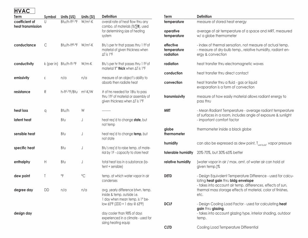
HVAC SYSTEMS
Single ZoneSingle DuctCVAll-Air
USAGE PROS CONS
S-M bldgs- Lobbies- Theaters- Dept Stores
- simple- low instal cost- few ductwork- good for control-ling IAQ (temp humidity filtering)
- few controls- heat or cool only- can be noisy fans run at peak condi-tion- thick distribution trees- bad for perim-eter zones in cold climates
SYSTEM
Multi ZoneSingle DuctCVAll-Air
[Single Zone]Single DuctVAVAll-Air
[Single Zone]Dual DuctCV(high-velocity)All-Air
M-L bldgs- Office w multiple tenants
- can heat amp cool at same time- greater temp control
- more ductwork- higher first cost
M-L bldgs- Office - Commercial
- saves energy because fans donrsquot need to run peak all the time = smaller fan- better for cool-ing interior load-dominated
doesnrsquot work as well for- perimeter zones when cold- extreme heat-ingcooling needs
M-L bldgs- Hospitals- Offices
- controls temp amp vol better flex-ibility comfort- efficient for partially occupied room- can heat amp cool at same time
- more expensive (more ducts)- more inefficient since hot amp cold running all the time- noisy- mostly replaced by VAV
NOTES
HVAC
[Single Zone]Single DuctFan-PoweredVAVAll-Air
- fan in VAV box- heating or cool-ing only- less ducting than multizone
[Single Zone]Single Ductw ReheatCVAll-Air
- small distribution tree- reduces air flow amp noise by con-trolling temp at space- good perim zones
- inefficient for diff needs since air cooled for lowest temp reqrsquod then reheated room
- Warehouse (anything w sim heatingcooling needs)
terminal re-heat = heating coils nr spacezone reheat = coils in duct
HVAC SYSTEMS USAGE PROS CONSSYSTEM NOTES
InductionWater-Air
Fan-Coil w Supplemen-tary AirWater-Air
- Hospitals- perim zone Schools Offices Labs
- greater control space- heatingcooling space- no recirc of return air
- expensive- extra distribution for water
- uses fan not high velocity pri-mary air
- extremes entry way- hospitals amp ar-eas w sensitive temp needs amp no return air
Radiant Panels w Supple-mentary AirWater-Air
- not efficient for perimeter zone that has changing heatingcooling needs
- controls volume at service space to control temp- larger bldgs (most popular system)
HVAC
Multi ZoneFan CoilAll Water
Multi ZoneFan CoilWater-Air
Heat PumpAll Water
Unitary
HVAC SYSTEMS USAGE PROS CONSSYSTEM NOTES
Induction Unit w Squirrel Cage Blower
- reduces exten-sive ducting
pulls outside into serviced space thru unit large bldgs w sep tenants
HVAC
- good for pe-rimeter zones w different temp needs- schools
- saves space w less duct work- water carries heatcool better than air more efficient
very common system
- good temp control for varied heatingcooling needs- has a heat exchanger (re-frigerants) unlike fancoil
SINGLE PIPE
TWO PIPE
THREE PIPE
FOUR PIPE
BOILER - Cast Iron
Advantages of Insulated Ductwork- reduce heat lossheat gain of air during delivery- isolates air noises in duct from spaces- prevents condensation on outside for cool-air ducts
opposed-blade balancing
splitter vanes
conventional turns
turning vanes
regulates flow of air
use where duct branches off for flow control
reduces friction at corners
reduces friction at corners
Damper Types Usage
ECONOMIZER CYCLE
- heating or cooling only- supply amp return in one loop
- heating or cooling only- faster delivery to ea zone
- separate heating amp cooling- shared return
- separate heating amp cooling- separate returns for heating amp cooling
HVAC
AHU - plan
AHU - section
Heat Pump - packaged air to air unit
Heat Pump - split system air to air
Heat Pump w solar hot water
HVAC - cooling cycle
HVAC - heating amp cooling
HVACcooling tower - use in more temperate climates where high cooling load not needed
chiller - use in hot climate w high cooling demands
Termhard water
anode
zeolite
turbidity
shallow well
well yield
suction pump
deep-well jet pumps
submersible
turbine pump
downfeed system
pneumatic system
tankless (wa-ter supply) system
DefinitionProperties- contains mineral deposists that can clog up piping- mineral build-up in heat exchangers lsquoinsulatesrsquo coils amp reduces abil-ity to exchange heat- bad for hydronic systems
a piece of metal placed in water tank to attract mineral deposits so they donrsquot form on tank amp equipment
ion exchange - water softening method in which hardwater passed thru zeolite minerals then salt tank so that minerals in hard water doesnrsquot solidify
caused by suspended material in water ie silt clay organic material
lt 25rsquo
gallons per minute
use for wells lt25rsquo deep
25rsquo-100rsquo+
moderate to deep wells privateresidential placed below waterline
high capacity deep wells
- tank mounted on roof supplies water to upper stories- pressure determined by height of tank above floor to be supplied amp not by pump- pressure at any level is constant- pressure at any fixture or point in system determined by dist from outlet of tank to fixture 0434 psift- height of zone = max allowable pressure on fixtures at bottom of zone (usually 45-60 psi)
- uses pressurized tank in basement to supply higher levels- air in tank can be compressed to lsquopushrsquo water can cause some air to dissolve in water
- uses variable speed pumps that run at varying rates turns offon to provide necessary pressure depending on demand rates- saves space but pumps wear out faster
Pipe Typesteelgalv stl
copper
K
L
M
plastic
PE ABS PVC PVDC
min vent dia
critical distance
14rdquoft
450
fixture unit
Notedefinition- sched 40 most common only used for non-corrosive water- harder to assemble
- resists corrosion high strength low friction small outside diameter- harder to connect more expensive
- thickest wall- comes in straight lengths (hard temper) or coils (soft temper)- greatest strength used for underground supply
- thinner than K- straight lengths or coils- most common grade for most plumbing systems
- thinnest- straight lengths only- only use at low pressure ie branch supply lines chilled water ex-posed lines in heating drainage piping
still restricted by some codes
polyethyleneacrilylonitrile-butadiene styrenepolyvinyl chloridepolyvinyl dichloride - ok for hot water
1-14rdquo or 12 dia of serviced drain larger of the twoas load decreases vent size can be reduced but must be gt 12 dia of largest vent reqrsquod
max length of drain pipe between a trap amp air vent le 48X pipe dia
pipe slope for effluent flow
pipe slope for sewage that flows entirely by gravity
(FU) defines probable demands on plumbing fixtures1 FU = 1 unit flow rate of one ft3min
PLUMBING
GATE- ONOFF only- min control- can cause turbulence when fully opened
GLOBE CHECK ANGLE- ONOFF - meters flow- can restrict flow when fully opened
- backflow preventer
- controls flow- restrict ca-pabilities
steel copper plastic
VENT STACK VS STACK VENT
PLUMBING
UP-FEEDDOWN-FEED RESIDENTIAL WATER SYSTEMUP-FEEDDOWN-FEED RESIDENTIAL WATER SYSTEM
PLUMBING
TERM UNITS (US) DEFINITIONcurrent
energy
resistance
voltage
power
impedance
power factor
reactance
A
W-hr Ω
V
W
Ω
na
unit flow of electrons in a con-ductor
power (W) x time (hr)
unit of electromotive force or potential diff that will cause a current of 1A to flow thru con-ductor w resistance 1 Ω
energy time (hr) (rate of en-ergy transfer)
resistance in AC circuit
phase difference btwn volt-age amp current in AC circuit (0-1)
part of electrical resistance in AC circuit caused by induc-tance and capacitance
SYMBOLI
E R
V
P
Z
PF
UNITS (SI)A
W-h
Ω
V
W
Ω
na
Wire Types UsageCOPPER
ALUMINUM
ROMEX
BX
busbar busway
residential smaller bldgs
commercial
residential wood-framed le 3 stories
remodel work residential
P (W) = I (A) x V power in DC circuit P (W) = I (A) x V x PF power in AC circuit P (W) = I (A) x V x PF x radic3 power in AC 3-phase circuit
I (A) = V R (Ω) Ohmrsquos Law
Rtot = R1 + R2 +Rn resistance in series 1Rtot = 1R1 + 1R2 +1Rn resistance in parallel
Notedefinition- same carrying capacity as alum but smaller cheaper
- larger than copper for same capacity but lighter - requires specialized installer- oxide can form when joints loosened overheats
- nonmetallic sheathed cable- 2+ plastic insulated conductors- must be protected from damage- ie win walls- no conduit reqrsquod gt cheaper
- flexible metal clad cable- 2+ plastic insulated conductors encased in spiral-wound strip of steel tape- no conduit reqrsquod can be easily pulled
- rectangular bars of copper carry high voltage
- multiple busbars in a metal housing
Conduit Typesrigid steel
intermediate metal
flexible metal (flex)
electric metallic tubing
Notedefinition- connects to J-boxes amp devices w threaded fittings
- thinner walls same outside dia as rigid use w thread-ed fittings
- reduce vibration transmission from equip where not possible to install rigid
- installed w special pressure fittings - too thin to thread- easierfaster install- NOT allowed in hazardous areas
SM
LRG
PhaseVoltage111333333
333
120120240240120240480208120208480277480
2400416041604160
Wires233433434
433
Usage
residential small bldgs actual load le 80Acommercialldquohigh leg deltardquo found only in older bldgscommercial
larger bldgs more variety of loadscommerciallarger bldgs smaller feeders conduit sizes switch gears than lower voltagex-large commercial bldgs factories
Connection2-wire3-wireDeltaDeltaDeltaWyeWyeWyeWye
WyeDeltaWye
3-wire used for higher voltage transmission circuits4-wire used for distribution voltage circuits more flexibility in bldgs
ELECTRICAL
Single Pole Single Throw
Single Pole Double Throw
Single-Pole Single-Throw
Double-Pole Single-Throw
Triple-Pole amp Sold-Neu-tral (3P amp SN)
Single-Pole Double-Throw (3-Way Switch)
Single-Pole Double-Throw w center ldquooffrdquo position (in control work called a hand-off automatic switch)
(2) Single-Pole Double-Throw (3-way) switches for switching of a lighting circuit from (2) locations
Commonly used in a step-down transformer wyeconnection on the HV side reduces insulation costs the neutral point on the HV side can be grounded
stable with respect to unbalanced loads
Commonly used in a step-up transformer for thesame reasons as above
Offers the advantage that one of the transform-ers can be removed while the remaining twotransformers can deliver three-phase power at 58 of the original bank
Wye-Delta
Delta-Wye
Delta-Delta
Wye-Wye
ELECTRICAL
switch gearfor large buildings the central elec distribution centerFrom switchgear power is distributed to - Substations for further transforming and distribution - Elevator controls - Motor control centers - Individual panel boxes
outlets (In residential construction)- no more than 12rsquo-0rdquo apart- or no point is more than 6rsquo from an outlet- circuits are 15A- Min two 20A for applianceskitchens amp baths- Servicing countertop area must be supplied from at least two separate circuits- No more than four outlets per 20A circuit- Outlets in kitchen laid out so no point on wall above counter is more than 24rdquofrom outlet- At least one outlet between appliances and sink so no cord has to be drapedacross appliances and sink- Outlets within 6rsquo of sink must be GFCI
TERM UNITS (US) DEFINITIONcandlepower
illuminance
luminance
lumen
luminous flux
radiant flux
luminous intensity
luminous efficacy
flux
cp
fc (lmft2)
fL (cpft2)
lm
lm
lm
cp
lmW
unit of luminous flux intensity
density of luminous flux
luminous flux per unit of pro-jected area
amount of energy emanating from 1m2 or 1ft2 of surface on a sphere 1m or 1ft from light source of 1cd light output
rate of flow of perceived light energy = power sim to Watt
measure of the total power of light emitted
sim to pressure or voltage force that generates visible light
luminous flux radiant flux
flow per unit area
SYMBOL
E
L
Φ
I
UNITS (SI)cd
lux
nit (cdm2)
lm
lm
lm
cd
lmW
TERM DEFINITIONglare
directdiscomfort glare
reflected glare veiling reflection
VCP
contrast
DF
excessive luminance in the field of vision
glare caused by direct light sources in field of vision
glare caused by reflection of light source in a viewed surface
Visual Comfort Probability - of normal observers who may be expected to experience visual comfort in an given environment w given lighting
difference in illumination level between one point and nearby points- 113 between task amp adjacent surroundings- 1 15 between task and more remote darker surfaces- 1110 between task and more remote lighter surfaces
Daylight Factor = indoor illuminance outdoor illuminance not direct sunlight
Lamp Type Characteristicsincandescent
fluorescent- preheat - rapid start- instant start
mercury vapor
metal halide
hi-pressure sodium
low pressure sodium
tungsten filament inside sealed bulb w inert gas
inert gas amp low pressure mercury vapor w phos-phor-coated bulb
blue-green light
monochrome yel-low light
Usageanywhere indoor
anywhere indoor
street lights
PROrsquoscheap dim-mable small easy instal
longer lamp life more efficient (80 lmW)
30-50 lmW
50-100 lmW ok CR
80-140 lmW ok CR
high efficacy (150 lmW)
CONrsquosinefficient- lots of heat short lamp life
slow to start amp lsquocoolrsquo color but improved now
poor color rendi-tionhi
gh in
tens
ity d
ischa
rge
(HID
)
LIGHTING
ballast- component of fluorescent amp HID lamps that controls voltage amp current inorder to provide circuit conditions that are needed to start amp operate a lamp- produces noise amp heat
Incandescent Lamps- Tungsten filament set within a sealed bulb containing inert gas- A-21 indicates shape and the diameter of bulb at widest point measured in eights which is 218 or 2 58rdquodia
Lamp types- A Arbitrary (standard shape)- PS pear shape straight neck- P pear shape- S straight- G globe- T tubular- PAR parabolic aluminized reflector- R reflector- ER elliptical reflector- MR miniature reflector
Inverse Square LawE = Id2
Equivalent spherical illumination (ESI) theoretical sphere surrounding object being illuminatedwith light cast evenly from all parts eliminating any shadows and reflected bright spots
Isolux chart (isofootcandle chart) diagram showing lines of equal illumination produced by aspecific luminaire from a particular manufacturer
Energy Budgets- Code requirements concerning the maximum amount of power that can be consumed in a building for lighting- Approx 23Wft2 considered a max
LIGHTING
isolux chart
TERM UNITS (US) DEFINITIONcoefficient of absorption
total acoustical absorption
velocity of sound
frequency of sound
transmission loss
intensity
sound intensity
sound intensity level
noise reduction
acoustic power
distance from source
barrier area btwn rooms
coefficient of transmission
reverberation time
room volume
power
wavelength
-
sabins (ft2)
ftsec
Hz
-
-
-
dB
-
W
ft
ft2
-
sec
ft3
W
ft
sound intensity absorbed total intensity reaching material (0-1)
1 ft2 of surface w A = 10
1 Hz = 1 cycle per second
diff btwn sound incident on barrier amp sound radiated on other sideamt of sound energysec across a unit area
SYMBOLa
A
c
f
TL
I
IL
NR
P
r
S
t
T
V
W
w
UNITS (SI)-
sabins (m2)
ms
Hz
-
Wcm2
10-16Wcm2
dB
-
W
cm
m2
-
s
ft3
W
m
TERM DEFINITIONarticulation index
attenuation
IIC
intensity level
IIC
NC
NIC
NR
NRC
STC
reverberation
reverberation time
measure of speech intelligibility low (015) = good for privacy high (06) = good for communication
reduction of sound
Impact Insulation Class - single-number measure rating of floor-ceil-ingrsquos impact sound transmission performance various frequen-cies
10x the common log of ratio of sound intensity to a reference intensity - decibel
Impact Isolation Class - rating of floorceilingrsquos impact on sound performance
Noise Criteria - single number ratings of acceptable background noise corresponding to set of curves specifying sound pressure levels across octave bands Used to- specify continuous background noise- achieve sound isolation- evaluate existing noise situations
Noise Insulation Class - single number rating of noise reduction
Noise Reduction - (dB) difference btwn intensity levels in 2 rooms separated by barrier of given transmission loss Depends on- transmission loss of barrier- area of barrier- absorption of surfaces of receiving room
Noise Reduction Coefficient - avg sound absorption coefficient
Sound Transmission Class - single number av over several frequen-cies of barrierrsquos ability to reduce sound higher = better
persistence of a sound in a room after the source has stopped
time it takes for sound level to decrease 60 dB after source stopped
Sabinrsquos formula T = (005) x (VA)
inverse square law I1 I2 = r2
2 r12
sound intensity I = P 4πr2
ACOUSTICS
focusing creep
flat diffuser
Sound Path Definition Remedy (if not desired)specular reflection
echo
flutter
diffusion
focusing
creep
flanking
leakloss
impact structure- borne
- when sound reflects off a hard polished surface- good for theaters w reflecting panels or when sound source placed above listeners
- reflected sound reaches listener gt50 ms after itrsquos first heard- undesirable for theaters
- repeated echoes traversing back amp forth btwn 2 non-absorb-ing parallel surfaces- perceived as buzzing or clicking sounds
- sound reflected from convex surfaces- sound level relatively constant thru out space - good for music
- sound reflected from convex surfaces - limited reception
- reflection of sound along a curved surface from a source near the surface
- transmission of sound from one room to another by indirect paths ie plenum ductwork vents
- transmission thru openings ie partition edges windows outlets
- originates from mechphysical contact
- sound absorptive materials
- use sound absorptive materials on back wall in theaters - reduce back wall area- add reflecting panel above stage
- change shape of reflector- add absorption
- change shape of reflector- add absorption
- change shape of reflector
- change shape of reflector
- interior duct linings baffles silencers better seals- separate ducts to each space
- better window layouts- acoustic insulation amp better seals- active noise cancellation
- isolation pads amp springs for mech equip
inclined flat convex (most diffusion)
theater acoustics
Addition of Decibels - Approximationdiff btwn 2 values add to higher value0 or 1 dB 3 dB2 or 3 2 dB4 or 8 1 dB9 or more 0 dB
ACOUSTICS
INCIDENT NOISE
TRANSMITTED NOISE
ACOUSTICS
VERTICAL TRANSPORTATION HYDRAULIC ELEVATORS-Lifted by plunger or ram with oil as pressure fluid- Cylinder for the ram extended into ground depth the same as elevator height-25fpm ndash 150fpm-2-6 story buildings or 50rsquo- Single ram from 2000lbm to 20000lbm- Multiple ram 20000lbm to 100000lbm Holeless hydraulic telescoping plunger next to cab lifts by applying pressure to upper member of cab frame Roller chain mounted over a wheel mounted on top of plunger w plunger mounted above the ground in the side of the shaft
ELECTRIC ELEVATORS- higher lifts and greater speeds- Precisely controlled acceleration and deceleration Traction elevators Cable suspended Ropes draped over a sheave and attached to counterweight Motor drives sheave which transmits lifting power Counterweight is cab + 40 - 250fpm to 1800fpm - Capacities from 2000 to 5000lbm - Gearless traction elevator uses DC powered motor directly connected to the sheave - Geared traction elevator slow speeds from 25fpm to 450 fpmRoping- Double wrap rope wound over sheave twice in high speed elevators for additional traction- More bends = shorter life- 11 roping when rope connected to counterweight where cable travels as far as car in opp dir- 21 roping rope wraps sheave on counterweight and connects to top of the shaft rope movestwice as far as cab- Requires less weight to be lifted 1048577 smaller higher speed motor used- Desirable for speeds up to 700 fpm
- Operation the way the electrical systems for an elevator answer calls for service- Control method of coordinating all aspects of elevator service such as travel speed acceleratingdecelerating door opening speed and delay leveling and hall lantern signals- Single Automatic first automated system wo single call button on each floor and single button foreach floor inside car- Called if no one is using it- Passenger has exclusive use of the car until rip is complete- Selective collective operation most common remembers and answers calls in oone directionthen reverses When trip complete programmed to return to a home landing- Group automatic operation for large buildings with many elevators which are controlled withprogrammable microprocessors to respond
ELEVATORS
Safety Devicesbull If power failure brakes automatically appliedbull Governor senses speed and if limit exceeded brake is appliedbull Rail clamp grips side railsbull Car buffers stops motion if it over travels lowest stopbull Safety edges movable strips on edge of door that activates a switch to reopen if something contacts itbull Photoelectric devices amp proximity detectors serve same purposebull Sensors under floor detect max weight reached thru deflection of floorbull If power failure all cars stop but codes require emergency power to operate at least one car- Code require if fire alarm activated all cars return to lobby wo stopping amp switch to manual mode only operable by fire dept
Historybull Human animal and water powered as early as 3rd century BCbull Sir William Armstrong 1846 inspired by hydraulic crane to invent the hydraulic elevator- 1870 hydraulic elevator began to replace steam powered elevatorbull Elishia Graves Otis 1853 invented brake safety device- Due to increased safety allowed feasibility of high rises- 1900 Otis co first introduced escalatorbull Werner von Siemens 1880 first electric elevator Handling capacity number of people to be served usually based on a 5-min peak periodbull Max number of passengers in car related to capacity in weightbull Recommended elevator speeds available based on the number of floors served and size of building
Number of Elevators Required based on- capacity- speed - door opening and closing time- delays amp stops the average round trip time can be calculated and then handling capacity of the car in a given- 5-min period can be determined- Number of elevators required is then found by total number of people to be ac-commodated in a 5-min peak and dividing by capacity of one car- Interval average wait time- Diversified offices 30 ndash 35sec- Hotels and apartments 40 ndash 70sec
Location and Lobby Designbull Min two elevators except in smallest applications so one available if one being servicedbull Easy to see all hall lanterns from one point (important for barrier free design)bull Never more than eight cars in a group or more than four cars in a linebull Taller and larger elevators to serve all floors increases proportion of shaft area to floor area increases beyond economic levels
- Becomes impossible for single elevator to serve more than 12 ndash 15 floors wo ex-ceeding acceptable waiting and total travel times 1) divide number of elevators into banks that serve zones shafts still take up significant space 2) sky lobby 3) stacked or double decked elevator cabs
Other ADA Requirements- elevator not reqrsquod in an altered facility or lt 3 stories or lt3000 sf- car must self-level win 12rdquo of floor landing- raised braille 2rdquo high on both jambs 60rdquo AFF- automatic protective door re-opening- 5 sec min notification between when lantern visible amp when audible notification heard- 3 sec min door fully opened
ESCALATORS
- 30o from horizontal incline- min vertical clearance 7rsquo- speed 90-125 fpm standard 100 fpm- tread widths 24rdquo 32rdquo 40rdquo- treads = 16rdquo deep- risers = 8rdquo wide
VERTICAL TRANSPORTATION
FIRE PROTECTION METHODS1 Prevention
2 Early detection amp alarm
3 Quick exiting
4 Containment
5 Suppression
early
late
Sprinkler System Descriptionwet pipe
dry pipe
pre-action
deluge
continuously filled w water responds 135-170F head
filled w compressed air amp nitrogen
1 early detector triggered fills pipe w water2 sprinklers activated amp openuse to limit water damage
upon alarm activation all sprinkler heads open at once in an area regardless of where fire is
CODES
IBC Bldgs gt 75ft must be sprinklered
NFPA 13
Usagemost places
outdoor uncon-ditioned areas prone to freezing
limit water damage
high-hazard rapid fire spread risk
Standpipe Descriptionstandpipe
Class I
Class II
Class III
- pipe that runs height of bldg amp provides water outlets ea floor to which fire fighting hoses can be connected- can be combined w sprinkler riser but need adequate pressure usually 2 separate pipes
- 2 12rdquo fire dept connection (fire dept use only)- dry system wo direct connection to water supply- siamese fittings outside street level- ball drip at bottom to ensure remains dry
1 12rdquo outlets amp hoses for use by bldg occu-pants- wet system directly connected to water sup-ply- every point of every floor must be win 130rsquo of outlet (100rsquo long hose w 30rsquo spray)- min 35 gpm 25psi 30 min- water supply min 70 gpm 25psi 30 min
- combination of I + II- 1 12rdquo amp 2 12rdquo outlets (siamese connections)
Usagelocate win stair wells vestibules
floor level of high-est story 30rsquo above or below fire truck access (IBC)
Extinguisher DescriptionA
B
C
D
water or water-based agents
smothering chemicals ie CO2 foam haloge-nated agents
nonconductive agents
Usageordinary
flammable
electrical
combustible
FIRE PROTECTION
1 INCIPIENT
2 SMOLDERING
3 FLAME
4 HEAT
- invisible products of combustion given off- no visible flame- no significant heat or smoke
- visible smoke
- fire is present - still not significant amount of heat
- openly burning visible flame- lots of heat smoke
ionizationgas
photoelectric
ultravioletinfrared radiation
heat activatedtemp detector fusible link
Stage of Fire DescriptionDetection Type
Sprinkler Required Groups A B (ambulatory health care facilities) E F-1 H I M R S-1 S-2 (enclosed parking garages) specific building areas amp hazards during con-struction (903212)
Standpipes Class I (9054) standpipe hose connections shall be provided in all of the following locations [F]
1 In every required stairway a hose connection shall be provided for each floor level above or below grade Hose connections shall be located at an intermedi-ate floor level landing between floors unless otherwise approved by the fire code official
2 On each side of the wall adjacent to the exit opening of a horizontal exit
Class II (9055) standpipe hose connections shall be accessible and located so that all portions of the building are within 30 feet (9144 mm) of a nozzle attached to 100 feet (30 480 mm) of hose [F]
Class III (90531) standpipe systems shall be installed throughout buildings where the floor level of the highest story is located more than 30 feet (9144 mm) above the lowest level of fire department vehicle access or where the floor level of the lowest story is located more than 30 feet (9144 mm) below the highest level of fire depart-ment vehicle access [F]
Exceptions1 Class I standpipes are allowed in buildings equipped throughout with an auto-matic sprinkler system in accordance with Section 903311 or 903312
2 Class I manual standpipes are allowed in open parking garages where the high-est floor is located not more than 150 feet (45 720 mm) above the lowest level of fire department vehicle access
3 Class I manual dry standpipes are allowed in open parking garages that are sub-ject to freezing temperatures provided that the hose connections are located as required for Class II standpipes in accordance with Section 9055
4 Class I standpipes are allowed in basements equipped throughout with an auto-matic sprinkler system
5 In determining the lowest level of fire department vehicle access it shall not be required to consider 51 Recessed loading docks for four vehicles or less and 52 Conditions where topography makes access from the fire department vehicle to the building impractical or impossible
Ventilation (120341)The minimum openable area to the outdoors shall be 4 percent of the floor area being ventilated
Equipment and systems (12041)Interior spaces intended for human occupancy shall be provided with active or passive space-heating systems capable of maintaining a minimumindoor temperature of 68degF (20degC) at a point 3 feet (914 mm) above the floor on the design heating day
Natural light (12052)The minimum net glazed area shall not be less than 8 percent of the floor area of the room served
Artificial light (12053 )Artificial light shall be provided that is adequate to provide an average illumination of 10 foot-candles(1 07 lux) over the area of the room at a height of 30 inches (762mm) above the floor level
Stairway illumination (12054)Stairways within dwelling units and exterior stairways serving a dwelling unit shall have an illumination level on tread runs of not less than 1 foot-candle
Air-borne sound (12072)Walls partitions and floorceiling assemblies separating dwelling units from each other or from public or service areas shall have a sound transmission class (STC) of not less than 50 (45 if field tested) for air-borne noise when tested in accordance with ASTM E 90
Structure-borne sound (12073)Floorceiling assemblies between dwelling units or between a dwelling unit and a public or service area within the structure shall have an impact insulation class (lIC) rating of not less than 50 (45 if field tested) 130111 Criteria Buildings shall be designed and constructed in accordance with the International Energy Conserva-tion Code
Number of elevator cars in a hoistway (30022) Where four or more elevator cars serve all or the same portion of a building the elevators shall be located in at least two separate hoistways Not more than four elevator cars shall be located in any single hoistway enclosure
CODES
48rdquo
48rdquo
CODES
COMMUNICATION + SIGNALSecurity System Descriptionpassive infrared
motion detector
mechanical motion detector
photoelectric
acoustic
normally closed contact device
- senses rapid change in infrared radiation or heat win zone - used when motion is expected- can be triggered by HVAC systems
- uses microwave or ultrasonic frequencies- doppler effect- lateral movement may be undetected place in line w likely path of travel
- spring mounted contact suspended win another contact surface- requires sensitivity adjustments to avoid false alarms
- triggered by interruption in a laser or infrared beam- can be triggered by dust birds weather etc if outside
- triggered when noise level exceeds preset limit- can be set to respond to frequency of breaking glass
- magnetic strip or spring loaded devices doors amp win-dows- triggered when circuit opened
Term Units (US) Definitioncoefficient of heat transmission
conductance
conductivity
emissivity
resistance
heat loss
latent heat
sensible heat
specific heat
enthalphy
dew point
degree day
design day
Btuh-ft2-degF
Btuh-ft2-degF
Btuh-ft-degF
na
h-ft2-degFBtu
Btuh
Btu
Btu
Btu
Btu
degF
na
overall rate of heat flow thru any combo of materials (1sumR) used for determining size of heating system
Btursquos per hr that passes thru 1 ft2 of material of given thickness when ΔT is 1degF
Btursquos per hr that passes thru 1 ft2 of material 1rdquo thick when ΔT is 1degF
measure of an objectrsquos ability to absorb then radiate heat
of hrs needed for 1Btu to pass thru 1ft2 of material or assembly of given thickness when ΔT is 1degF
---------
heat reqrsquod to change state but not temp
heat reqrsquod to change temp but not state
Btursquos reqrsquod to raise temp of mate-rial by 1F - capacity to store heat
total heat loss in a substance (la-tent + sensible)
temp at which water vapor in air condenses
avg yearly difference btwn temp inside amp temp outside ie1 day when mean temp is 1deg be-low 65degF (2DD = 1 day 63degF)
day cooler than 98 of days experienced in a climate - used for sizing heating equip
SymbolU
C
k (per in)
ε
R
q
H
T
DD
Units (SI)Wm2-K
Wm2-K
Wm-K
na
m2-KW
W
J
J
J
J
degC
na
HVACDefinitionmeasure of stored heat energy
average of air temperature of a space and MRT measured w a globe thermometer
- index of thermal sensation not measure of actual temp- measure of dry-bulb temp relative humidity radiant en-ergy amp convection
heat transfer thru electromagnetic waves
heat transfer thru direct contact
heat transfer thru a fluid - gas or liquidevaporation is a form of convection
measure of how easily material allows radiant energy to pass thru
- Mean Radiant Temperature - average radiant temperature of surfaces in a room includes angle of exposure amp sunlight- important comfort factor
thermometer inside a black globe
can also be expressed as dew point Twet-bulb vapor pressure
20-70 but 30-65 better
[water vapor in air max amt of water air can hold at given temp]
- Design Equivalent Temperature Difference - used for calcu-lating heat gain thru bldg envelope- takes into account air temp differences effects of sun thermal mass storage effects of material color of finishes etc
- Design Cooling Load Factor - used for calculating heat gain thru glazing - takes into account glazing type interior shading outdoor temp
Cooling Load Temperature Differential
Termtemperature
operative temperature
effective temperatureradiation
radiation
conduction
convection
transmissivity
MRT
globe thermometer
humidity
tolerable humidity
relative humidity
DETD
DCLF
CLTD
Fuel Type Heating Valueelectricity
propane
natural gas
no 2 oil
anthracite coal
steam
3413 BthkW
2500 Btuft3
1050 Btuft3
137000- 141000 Btugal
na
Prorsquoseasy install amp control simple operation flex-ible zoning little space reqrsquod
portable good for remote areas
most efficient fossil fuel clean burning
portable amp storable
efficient in urban ar-eas from central plant from by-products
most expensive esp for high heating loads
not as clean burning as natural gas
canrsquot use in remote areas
wide price fluctuations burning equip need lots of maintenance must be stored nr use
Conrsquos95-100
70-90
70-80
65-85
65-75
na
Efficiency
compressive refrigeration absorption coolingrefrigerant in gas form absorbs heat from air gets compressed into liquid amp releases heat
- uses evaporation to lose heat- produces chilled water- closed loop system- salt solution in absorber needs to be boiled off as it absorbs water done via steam or solar
HVAC
ALL AIR = Air heated or cool at plant amp distributed by fans via ducts Each zone has supply amp return
Higher velocity air = smaller duct but noisier system
DX = direct expansion incremental unit self-contained unit passes nonducted air over evaporator for cooling installed on exterior walls
crack method- aka air change method used for deter-mining amount of air infiltration- measured in linear feet ie 4x4 window has 16rsquo of crack
qi = 0018 x Qcfh x ΔTqi = infiltration load heat reqrsquod (Btu)Qcfh = air amount (ft3hr)ΔT = Tinside - Touside
HVAC SYSTEMS
Single ZoneSingle DuctCVAll-Air
USAGE PROS CONS
S-M bldgs- Lobbies- Theaters- Dept Stores
- simple- low instal cost- few ductwork- good for control-ling IAQ (temp humidity filtering)
- few controls- heat or cool only- can be noisy fans run at peak condi-tion- thick distribution trees- bad for perim-eter zones in cold climates
SYSTEM
Multi ZoneSingle DuctCVAll-Air
[Single Zone]Single DuctVAVAll-Air
[Single Zone]Dual DuctCV(high-velocity)All-Air
M-L bldgs- Office w multiple tenants
- can heat amp cool at same time- greater temp control
- more ductwork- higher first cost
M-L bldgs- Office - Commercial
- saves energy because fans donrsquot need to run peak all the time = smaller fan- better for cool-ing interior load-dominated
doesnrsquot work as well for- perimeter zones when cold- extreme heat-ingcooling needs
M-L bldgs- Hospitals- Offices
- controls temp amp vol better flex-ibility comfort- efficient for partially occupied room- can heat amp cool at same time
- more expensive (more ducts)- more inefficient since hot amp cold running all the time- noisy- mostly replaced by VAV
NOTES
HVAC
[Single Zone]Single DuctFan-PoweredVAVAll-Air
- fan in VAV box- heating or cool-ing only- less ducting than multizone
[Single Zone]Single Ductw ReheatCVAll-Air
- small distribution tree- reduces air flow amp noise by con-trolling temp at space- good perim zones
- inefficient for diff needs since air cooled for lowest temp reqrsquod then reheated room
- Warehouse (anything w sim heatingcooling needs)
terminal re-heat = heating coils nr spacezone reheat = coils in duct
HVAC SYSTEMS USAGE PROS CONSSYSTEM NOTES
InductionWater-Air
Fan-Coil w Supplemen-tary AirWater-Air
- Hospitals- perim zone Schools Offices Labs
- greater control space- heatingcooling space- no recirc of return air
- expensive- extra distribution for water
- uses fan not high velocity pri-mary air
- extremes entry way- hospitals amp ar-eas w sensitive temp needs amp no return air
Radiant Panels w Supple-mentary AirWater-Air
- not efficient for perimeter zone that has changing heatingcooling needs
- controls volume at service space to control temp- larger bldgs (most popular system)
HVAC
Multi ZoneFan CoilAll Water
Multi ZoneFan CoilWater-Air
Heat PumpAll Water
Unitary
HVAC SYSTEMS USAGE PROS CONSSYSTEM NOTES
Induction Unit w Squirrel Cage Blower
- reduces exten-sive ducting
pulls outside into serviced space thru unit large bldgs w sep tenants
HVAC
- good for pe-rimeter zones w different temp needs- schools
- saves space w less duct work- water carries heatcool better than air more efficient
very common system
- good temp control for varied heatingcooling needs- has a heat exchanger (re-frigerants) unlike fancoil
SINGLE PIPE
TWO PIPE
THREE PIPE
FOUR PIPE
BOILER - Cast Iron
Advantages of Insulated Ductwork- reduce heat lossheat gain of air during delivery- isolates air noises in duct from spaces- prevents condensation on outside for cool-air ducts
opposed-blade balancing
splitter vanes
conventional turns
turning vanes
regulates flow of air
use where duct branches off for flow control
reduces friction at corners
reduces friction at corners
Damper Types Usage
ECONOMIZER CYCLE
- heating or cooling only- supply amp return in one loop
- heating or cooling only- faster delivery to ea zone
- separate heating amp cooling- shared return
- separate heating amp cooling- separate returns for heating amp cooling
HVAC
AHU - plan
AHU - section
Heat Pump - packaged air to air unit
Heat Pump - split system air to air
Heat Pump w solar hot water
HVAC - cooling cycle
HVAC - heating amp cooling
HVACcooling tower - use in more temperate climates where high cooling load not needed
chiller - use in hot climate w high cooling demands
Termhard water
anode
zeolite
turbidity
shallow well
well yield
suction pump
deep-well jet pumps
submersible
turbine pump
downfeed system
pneumatic system
tankless (wa-ter supply) system
DefinitionProperties- contains mineral deposists that can clog up piping- mineral build-up in heat exchangers lsquoinsulatesrsquo coils amp reduces abil-ity to exchange heat- bad for hydronic systems
a piece of metal placed in water tank to attract mineral deposits so they donrsquot form on tank amp equipment
ion exchange - water softening method in which hardwater passed thru zeolite minerals then salt tank so that minerals in hard water doesnrsquot solidify
caused by suspended material in water ie silt clay organic material
lt 25rsquo
gallons per minute
use for wells lt25rsquo deep
25rsquo-100rsquo+
moderate to deep wells privateresidential placed below waterline
high capacity deep wells
- tank mounted on roof supplies water to upper stories- pressure determined by height of tank above floor to be supplied amp not by pump- pressure at any level is constant- pressure at any fixture or point in system determined by dist from outlet of tank to fixture 0434 psift- height of zone = max allowable pressure on fixtures at bottom of zone (usually 45-60 psi)
- uses pressurized tank in basement to supply higher levels- air in tank can be compressed to lsquopushrsquo water can cause some air to dissolve in water
- uses variable speed pumps that run at varying rates turns offon to provide necessary pressure depending on demand rates- saves space but pumps wear out faster
Pipe Typesteelgalv stl
copper
K
L
M
plastic
PE ABS PVC PVDC
min vent dia
critical distance
14rdquoft
450
fixture unit
Notedefinition- sched 40 most common only used for non-corrosive water- harder to assemble
- resists corrosion high strength low friction small outside diameter- harder to connect more expensive
- thickest wall- comes in straight lengths (hard temper) or coils (soft temper)- greatest strength used for underground supply
- thinner than K- straight lengths or coils- most common grade for most plumbing systems
- thinnest- straight lengths only- only use at low pressure ie branch supply lines chilled water ex-posed lines in heating drainage piping
still restricted by some codes
polyethyleneacrilylonitrile-butadiene styrenepolyvinyl chloridepolyvinyl dichloride - ok for hot water
1-14rdquo or 12 dia of serviced drain larger of the twoas load decreases vent size can be reduced but must be gt 12 dia of largest vent reqrsquod
max length of drain pipe between a trap amp air vent le 48X pipe dia
pipe slope for effluent flow
pipe slope for sewage that flows entirely by gravity
(FU) defines probable demands on plumbing fixtures1 FU = 1 unit flow rate of one ft3min
PLUMBING
GATE- ONOFF only- min control- can cause turbulence when fully opened
GLOBE CHECK ANGLE- ONOFF - meters flow- can restrict flow when fully opened
- backflow preventer
- controls flow- restrict ca-pabilities
steel copper plastic
VENT STACK VS STACK VENT
PLUMBING
UP-FEEDDOWN-FEED RESIDENTIAL WATER SYSTEMUP-FEEDDOWN-FEED RESIDENTIAL WATER SYSTEM
PLUMBING
TERM UNITS (US) DEFINITIONcurrent
energy
resistance
voltage
power
impedance
power factor
reactance
A
W-hr Ω
V
W
Ω
na
unit flow of electrons in a con-ductor
power (W) x time (hr)
unit of electromotive force or potential diff that will cause a current of 1A to flow thru con-ductor w resistance 1 Ω
energy time (hr) (rate of en-ergy transfer)
resistance in AC circuit
phase difference btwn volt-age amp current in AC circuit (0-1)
part of electrical resistance in AC circuit caused by induc-tance and capacitance
SYMBOLI
E R
V
P
Z
PF
UNITS (SI)A
W-h
Ω
V
W
Ω
na
Wire Types UsageCOPPER
ALUMINUM
ROMEX
BX
busbar busway
residential smaller bldgs
commercial
residential wood-framed le 3 stories
remodel work residential
P (W) = I (A) x V power in DC circuit P (W) = I (A) x V x PF power in AC circuit P (W) = I (A) x V x PF x radic3 power in AC 3-phase circuit
I (A) = V R (Ω) Ohmrsquos Law
Rtot = R1 + R2 +Rn resistance in series 1Rtot = 1R1 + 1R2 +1Rn resistance in parallel
Notedefinition- same carrying capacity as alum but smaller cheaper
- larger than copper for same capacity but lighter - requires specialized installer- oxide can form when joints loosened overheats
- nonmetallic sheathed cable- 2+ plastic insulated conductors- must be protected from damage- ie win walls- no conduit reqrsquod gt cheaper
- flexible metal clad cable- 2+ plastic insulated conductors encased in spiral-wound strip of steel tape- no conduit reqrsquod can be easily pulled
- rectangular bars of copper carry high voltage
- multiple busbars in a metal housing
Conduit Typesrigid steel
intermediate metal
flexible metal (flex)
electric metallic tubing
Notedefinition- connects to J-boxes amp devices w threaded fittings
- thinner walls same outside dia as rigid use w thread-ed fittings
- reduce vibration transmission from equip where not possible to install rigid
- installed w special pressure fittings - too thin to thread- easierfaster install- NOT allowed in hazardous areas
SM
LRG
PhaseVoltage111333333
333
120120240240120240480208120208480277480
2400416041604160
Wires233433434
433
Usage
residential small bldgs actual load le 80Acommercialldquohigh leg deltardquo found only in older bldgscommercial
larger bldgs more variety of loadscommerciallarger bldgs smaller feeders conduit sizes switch gears than lower voltagex-large commercial bldgs factories
Connection2-wire3-wireDeltaDeltaDeltaWyeWyeWyeWye
WyeDeltaWye
3-wire used for higher voltage transmission circuits4-wire used for distribution voltage circuits more flexibility in bldgs
ELECTRICAL
Single Pole Single Throw
Single Pole Double Throw
Single-Pole Single-Throw
Double-Pole Single-Throw
Triple-Pole amp Sold-Neu-tral (3P amp SN)
Single-Pole Double-Throw (3-Way Switch)
Single-Pole Double-Throw w center ldquooffrdquo position (in control work called a hand-off automatic switch)
(2) Single-Pole Double-Throw (3-way) switches for switching of a lighting circuit from (2) locations
Commonly used in a step-down transformer wyeconnection on the HV side reduces insulation costs the neutral point on the HV side can be grounded
stable with respect to unbalanced loads
Commonly used in a step-up transformer for thesame reasons as above
Offers the advantage that one of the transform-ers can be removed while the remaining twotransformers can deliver three-phase power at 58 of the original bank
Wye-Delta
Delta-Wye
Delta-Delta
Wye-Wye
ELECTRICAL
switch gearfor large buildings the central elec distribution centerFrom switchgear power is distributed to - Substations for further transforming and distribution - Elevator controls - Motor control centers - Individual panel boxes
outlets (In residential construction)- no more than 12rsquo-0rdquo apart- or no point is more than 6rsquo from an outlet- circuits are 15A- Min two 20A for applianceskitchens amp baths- Servicing countertop area must be supplied from at least two separate circuits- No more than four outlets per 20A circuit- Outlets in kitchen laid out so no point on wall above counter is more than 24rdquofrom outlet- At least one outlet between appliances and sink so no cord has to be drapedacross appliances and sink- Outlets within 6rsquo of sink must be GFCI
TERM UNITS (US) DEFINITIONcandlepower
illuminance
luminance
lumen
luminous flux
radiant flux
luminous intensity
luminous efficacy
flux
cp
fc (lmft2)
fL (cpft2)
lm
lm
lm
cp
lmW
unit of luminous flux intensity
density of luminous flux
luminous flux per unit of pro-jected area
amount of energy emanating from 1m2 or 1ft2 of surface on a sphere 1m or 1ft from light source of 1cd light output
rate of flow of perceived light energy = power sim to Watt
measure of the total power of light emitted
sim to pressure or voltage force that generates visible light
luminous flux radiant flux
flow per unit area
SYMBOL
E
L
Φ
I
UNITS (SI)cd
lux
nit (cdm2)
lm
lm
lm
cd
lmW
TERM DEFINITIONglare
directdiscomfort glare
reflected glare veiling reflection
VCP
contrast
DF
excessive luminance in the field of vision
glare caused by direct light sources in field of vision
glare caused by reflection of light source in a viewed surface
Visual Comfort Probability - of normal observers who may be expected to experience visual comfort in an given environment w given lighting
difference in illumination level between one point and nearby points- 113 between task amp adjacent surroundings- 1 15 between task and more remote darker surfaces- 1110 between task and more remote lighter surfaces
Daylight Factor = indoor illuminance outdoor illuminance not direct sunlight
Lamp Type Characteristicsincandescent
fluorescent- preheat - rapid start- instant start
mercury vapor
metal halide
hi-pressure sodium
low pressure sodium
tungsten filament inside sealed bulb w inert gas
inert gas amp low pressure mercury vapor w phos-phor-coated bulb
blue-green light
monochrome yel-low light
Usageanywhere indoor
anywhere indoor
street lights
PROrsquoscheap dim-mable small easy instal
longer lamp life more efficient (80 lmW)
30-50 lmW
50-100 lmW ok CR
80-140 lmW ok CR
high efficacy (150 lmW)
CONrsquosinefficient- lots of heat short lamp life
slow to start amp lsquocoolrsquo color but improved now
poor color rendi-tionhi
gh in
tens
ity d
ischa
rge
(HID
)
LIGHTING
ballast- component of fluorescent amp HID lamps that controls voltage amp current inorder to provide circuit conditions that are needed to start amp operate a lamp- produces noise amp heat
Incandescent Lamps- Tungsten filament set within a sealed bulb containing inert gas- A-21 indicates shape and the diameter of bulb at widest point measured in eights which is 218 or 2 58rdquodia
Lamp types- A Arbitrary (standard shape)- PS pear shape straight neck- P pear shape- S straight- G globe- T tubular- PAR parabolic aluminized reflector- R reflector- ER elliptical reflector- MR miniature reflector
Inverse Square LawE = Id2
Equivalent spherical illumination (ESI) theoretical sphere surrounding object being illuminatedwith light cast evenly from all parts eliminating any shadows and reflected bright spots
Isolux chart (isofootcandle chart) diagram showing lines of equal illumination produced by aspecific luminaire from a particular manufacturer
Energy Budgets- Code requirements concerning the maximum amount of power that can be consumed in a building for lighting- Approx 23Wft2 considered a max
LIGHTING
isolux chart
TERM UNITS (US) DEFINITIONcoefficient of absorption
total acoustical absorption
velocity of sound
frequency of sound
transmission loss
intensity
sound intensity
sound intensity level
noise reduction
acoustic power
distance from source
barrier area btwn rooms
coefficient of transmission
reverberation time
room volume
power
wavelength
-
sabins (ft2)
ftsec
Hz
-
-
-
dB
-
W
ft
ft2
-
sec
ft3
W
ft
sound intensity absorbed total intensity reaching material (0-1)
1 ft2 of surface w A = 10
1 Hz = 1 cycle per second
diff btwn sound incident on barrier amp sound radiated on other sideamt of sound energysec across a unit area
SYMBOLa
A
c
f
TL
I
IL
NR
P
r
S
t
T
V
W
w
UNITS (SI)-
sabins (m2)
ms
Hz
-
Wcm2
10-16Wcm2
dB
-
W
cm
m2
-
s
ft3
W
m
TERM DEFINITIONarticulation index
attenuation
IIC
intensity level
IIC
NC
NIC
NR
NRC
STC
reverberation
reverberation time
measure of speech intelligibility low (015) = good for privacy high (06) = good for communication
reduction of sound
Impact Insulation Class - single-number measure rating of floor-ceil-ingrsquos impact sound transmission performance various frequen-cies
10x the common log of ratio of sound intensity to a reference intensity - decibel
Impact Isolation Class - rating of floorceilingrsquos impact on sound performance
Noise Criteria - single number ratings of acceptable background noise corresponding to set of curves specifying sound pressure levels across octave bands Used to- specify continuous background noise- achieve sound isolation- evaluate existing noise situations
Noise Insulation Class - single number rating of noise reduction
Noise Reduction - (dB) difference btwn intensity levels in 2 rooms separated by barrier of given transmission loss Depends on- transmission loss of barrier- area of barrier- absorption of surfaces of receiving room
Noise Reduction Coefficient - avg sound absorption coefficient
Sound Transmission Class - single number av over several frequen-cies of barrierrsquos ability to reduce sound higher = better
persistence of a sound in a room after the source has stopped
time it takes for sound level to decrease 60 dB after source stopped
Sabinrsquos formula T = (005) x (VA)
inverse square law I1 I2 = r2
2 r12
sound intensity I = P 4πr2
ACOUSTICS
focusing creep
flat diffuser
Sound Path Definition Remedy (if not desired)specular reflection
echo
flutter
diffusion
focusing
creep
flanking
leakloss
impact structure- borne
- when sound reflects off a hard polished surface- good for theaters w reflecting panels or when sound source placed above listeners
- reflected sound reaches listener gt50 ms after itrsquos first heard- undesirable for theaters
- repeated echoes traversing back amp forth btwn 2 non-absorb-ing parallel surfaces- perceived as buzzing or clicking sounds
- sound reflected from convex surfaces- sound level relatively constant thru out space - good for music
- sound reflected from convex surfaces - limited reception
- reflection of sound along a curved surface from a source near the surface
- transmission of sound from one room to another by indirect paths ie plenum ductwork vents
- transmission thru openings ie partition edges windows outlets
- originates from mechphysical contact
- sound absorptive materials
- use sound absorptive materials on back wall in theaters - reduce back wall area- add reflecting panel above stage
- change shape of reflector- add absorption
- change shape of reflector- add absorption
- change shape of reflector
- change shape of reflector
- interior duct linings baffles silencers better seals- separate ducts to each space
- better window layouts- acoustic insulation amp better seals- active noise cancellation
- isolation pads amp springs for mech equip
inclined flat convex (most diffusion)
theater acoustics
Addition of Decibels - Approximationdiff btwn 2 values add to higher value0 or 1 dB 3 dB2 or 3 2 dB4 or 8 1 dB9 or more 0 dB
ACOUSTICS
INCIDENT NOISE
TRANSMITTED NOISE
ACOUSTICS
VERTICAL TRANSPORTATION HYDRAULIC ELEVATORS-Lifted by plunger or ram with oil as pressure fluid- Cylinder for the ram extended into ground depth the same as elevator height-25fpm ndash 150fpm-2-6 story buildings or 50rsquo- Single ram from 2000lbm to 20000lbm- Multiple ram 20000lbm to 100000lbm Holeless hydraulic telescoping plunger next to cab lifts by applying pressure to upper member of cab frame Roller chain mounted over a wheel mounted on top of plunger w plunger mounted above the ground in the side of the shaft
ELECTRIC ELEVATORS- higher lifts and greater speeds- Precisely controlled acceleration and deceleration Traction elevators Cable suspended Ropes draped over a sheave and attached to counterweight Motor drives sheave which transmits lifting power Counterweight is cab + 40 - 250fpm to 1800fpm - Capacities from 2000 to 5000lbm - Gearless traction elevator uses DC powered motor directly connected to the sheave - Geared traction elevator slow speeds from 25fpm to 450 fpmRoping- Double wrap rope wound over sheave twice in high speed elevators for additional traction- More bends = shorter life- 11 roping when rope connected to counterweight where cable travels as far as car in opp dir- 21 roping rope wraps sheave on counterweight and connects to top of the shaft rope movestwice as far as cab- Requires less weight to be lifted 1048577 smaller higher speed motor used- Desirable for speeds up to 700 fpm
- Operation the way the electrical systems for an elevator answer calls for service- Control method of coordinating all aspects of elevator service such as travel speed acceleratingdecelerating door opening speed and delay leveling and hall lantern signals- Single Automatic first automated system wo single call button on each floor and single button foreach floor inside car- Called if no one is using it- Passenger has exclusive use of the car until rip is complete- Selective collective operation most common remembers and answers calls in oone directionthen reverses When trip complete programmed to return to a home landing- Group automatic operation for large buildings with many elevators which are controlled withprogrammable microprocessors to respond
ELEVATORS
Safety Devicesbull If power failure brakes automatically appliedbull Governor senses speed and if limit exceeded brake is appliedbull Rail clamp grips side railsbull Car buffers stops motion if it over travels lowest stopbull Safety edges movable strips on edge of door that activates a switch to reopen if something contacts itbull Photoelectric devices amp proximity detectors serve same purposebull Sensors under floor detect max weight reached thru deflection of floorbull If power failure all cars stop but codes require emergency power to operate at least one car- Code require if fire alarm activated all cars return to lobby wo stopping amp switch to manual mode only operable by fire dept
Historybull Human animal and water powered as early as 3rd century BCbull Sir William Armstrong 1846 inspired by hydraulic crane to invent the hydraulic elevator- 1870 hydraulic elevator began to replace steam powered elevatorbull Elishia Graves Otis 1853 invented brake safety device- Due to increased safety allowed feasibility of high rises- 1900 Otis co first introduced escalatorbull Werner von Siemens 1880 first electric elevator Handling capacity number of people to be served usually based on a 5-min peak periodbull Max number of passengers in car related to capacity in weightbull Recommended elevator speeds available based on the number of floors served and size of building
Number of Elevators Required based on- capacity- speed - door opening and closing time- delays amp stops the average round trip time can be calculated and then handling capacity of the car in a given- 5-min period can be determined- Number of elevators required is then found by total number of people to be ac-commodated in a 5-min peak and dividing by capacity of one car- Interval average wait time- Diversified offices 30 ndash 35sec- Hotels and apartments 40 ndash 70sec
Location and Lobby Designbull Min two elevators except in smallest applications so one available if one being servicedbull Easy to see all hall lanterns from one point (important for barrier free design)bull Never more than eight cars in a group or more than four cars in a linebull Taller and larger elevators to serve all floors increases proportion of shaft area to floor area increases beyond economic levels
- Becomes impossible for single elevator to serve more than 12 ndash 15 floors wo ex-ceeding acceptable waiting and total travel times 1) divide number of elevators into banks that serve zones shafts still take up significant space 2) sky lobby 3) stacked or double decked elevator cabs
Other ADA Requirements- elevator not reqrsquod in an altered facility or lt 3 stories or lt3000 sf- car must self-level win 12rdquo of floor landing- raised braille 2rdquo high on both jambs 60rdquo AFF- automatic protective door re-opening- 5 sec min notification between when lantern visible amp when audible notification heard- 3 sec min door fully opened
ESCALATORS
- 30o from horizontal incline- min vertical clearance 7rsquo- speed 90-125 fpm standard 100 fpm- tread widths 24rdquo 32rdquo 40rdquo- treads = 16rdquo deep- risers = 8rdquo wide
VERTICAL TRANSPORTATION
FIRE PROTECTION METHODS1 Prevention
2 Early detection amp alarm
3 Quick exiting
4 Containment
5 Suppression
early
late
Sprinkler System Descriptionwet pipe
dry pipe
pre-action
deluge
continuously filled w water responds 135-170F head
filled w compressed air amp nitrogen
1 early detector triggered fills pipe w water2 sprinklers activated amp openuse to limit water damage
upon alarm activation all sprinkler heads open at once in an area regardless of where fire is
CODES
IBC Bldgs gt 75ft must be sprinklered
NFPA 13
Usagemost places
outdoor uncon-ditioned areas prone to freezing
limit water damage
high-hazard rapid fire spread risk
Standpipe Descriptionstandpipe
Class I
Class II
Class III
- pipe that runs height of bldg amp provides water outlets ea floor to which fire fighting hoses can be connected- can be combined w sprinkler riser but need adequate pressure usually 2 separate pipes
- 2 12rdquo fire dept connection (fire dept use only)- dry system wo direct connection to water supply- siamese fittings outside street level- ball drip at bottom to ensure remains dry
1 12rdquo outlets amp hoses for use by bldg occu-pants- wet system directly connected to water sup-ply- every point of every floor must be win 130rsquo of outlet (100rsquo long hose w 30rsquo spray)- min 35 gpm 25psi 30 min- water supply min 70 gpm 25psi 30 min
- combination of I + II- 1 12rdquo amp 2 12rdquo outlets (siamese connections)
Usagelocate win stair wells vestibules
floor level of high-est story 30rsquo above or below fire truck access (IBC)
Extinguisher DescriptionA
B
C
D
water or water-based agents
smothering chemicals ie CO2 foam haloge-nated agents
nonconductive agents
Usageordinary
flammable
electrical
combustible
FIRE PROTECTION
1 INCIPIENT
2 SMOLDERING
3 FLAME
4 HEAT
- invisible products of combustion given off- no visible flame- no significant heat or smoke
- visible smoke
- fire is present - still not significant amount of heat
- openly burning visible flame- lots of heat smoke
ionizationgas
photoelectric
ultravioletinfrared radiation
heat activatedtemp detector fusible link
Stage of Fire DescriptionDetection Type
Sprinkler Required Groups A B (ambulatory health care facilities) E F-1 H I M R S-1 S-2 (enclosed parking garages) specific building areas amp hazards during con-struction (903212)
Standpipes Class I (9054) standpipe hose connections shall be provided in all of the following locations [F]
1 In every required stairway a hose connection shall be provided for each floor level above or below grade Hose connections shall be located at an intermedi-ate floor level landing between floors unless otherwise approved by the fire code official
2 On each side of the wall adjacent to the exit opening of a horizontal exit
Class II (9055) standpipe hose connections shall be accessible and located so that all portions of the building are within 30 feet (9144 mm) of a nozzle attached to 100 feet (30 480 mm) of hose [F]
Class III (90531) standpipe systems shall be installed throughout buildings where the floor level of the highest story is located more than 30 feet (9144 mm) above the lowest level of fire department vehicle access or where the floor level of the lowest story is located more than 30 feet (9144 mm) below the highest level of fire depart-ment vehicle access [F]
Exceptions1 Class I standpipes are allowed in buildings equipped throughout with an auto-matic sprinkler system in accordance with Section 903311 or 903312
2 Class I manual standpipes are allowed in open parking garages where the high-est floor is located not more than 150 feet (45 720 mm) above the lowest level of fire department vehicle access
3 Class I manual dry standpipes are allowed in open parking garages that are sub-ject to freezing temperatures provided that the hose connections are located as required for Class II standpipes in accordance with Section 9055
4 Class I standpipes are allowed in basements equipped throughout with an auto-matic sprinkler system
5 In determining the lowest level of fire department vehicle access it shall not be required to consider 51 Recessed loading docks for four vehicles or less and 52 Conditions where topography makes access from the fire department vehicle to the building impractical or impossible
Ventilation (120341)The minimum openable area to the outdoors shall be 4 percent of the floor area being ventilated
Equipment and systems (12041)Interior spaces intended for human occupancy shall be provided with active or passive space-heating systems capable of maintaining a minimumindoor temperature of 68degF (20degC) at a point 3 feet (914 mm) above the floor on the design heating day
Natural light (12052)The minimum net glazed area shall not be less than 8 percent of the floor area of the room served
Artificial light (12053 )Artificial light shall be provided that is adequate to provide an average illumination of 10 foot-candles(1 07 lux) over the area of the room at a height of 30 inches (762mm) above the floor level
Stairway illumination (12054)Stairways within dwelling units and exterior stairways serving a dwelling unit shall have an illumination level on tread runs of not less than 1 foot-candle
Air-borne sound (12072)Walls partitions and floorceiling assemblies separating dwelling units from each other or from public or service areas shall have a sound transmission class (STC) of not less than 50 (45 if field tested) for air-borne noise when tested in accordance with ASTM E 90
Structure-borne sound (12073)Floorceiling assemblies between dwelling units or between a dwelling unit and a public or service area within the structure shall have an impact insulation class (lIC) rating of not less than 50 (45 if field tested) 130111 Criteria Buildings shall be designed and constructed in accordance with the International Energy Conserva-tion Code
Number of elevator cars in a hoistway (30022) Where four or more elevator cars serve all or the same portion of a building the elevators shall be located in at least two separate hoistways Not more than four elevator cars shall be located in any single hoistway enclosure
CODES
48rdquo
48rdquo
CODES
COMMUNICATION + SIGNALSecurity System Descriptionpassive infrared
motion detector
mechanical motion detector
photoelectric
acoustic
normally closed contact device
- senses rapid change in infrared radiation or heat win zone - used when motion is expected- can be triggered by HVAC systems
- uses microwave or ultrasonic frequencies- doppler effect- lateral movement may be undetected place in line w likely path of travel
- spring mounted contact suspended win another contact surface- requires sensitivity adjustments to avoid false alarms
- triggered by interruption in a laser or infrared beam- can be triggered by dust birds weather etc if outside
- triggered when noise level exceeds preset limit- can be set to respond to frequency of breaking glass
- magnetic strip or spring loaded devices doors amp win-dows- triggered when circuit opened
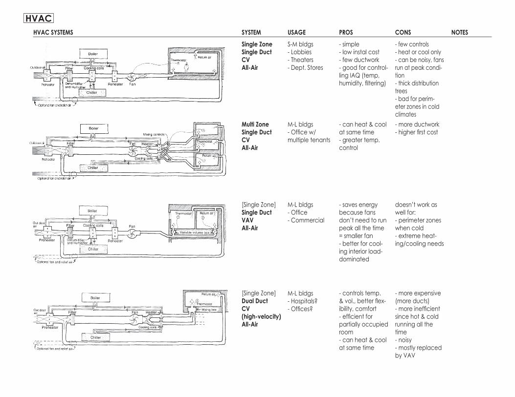
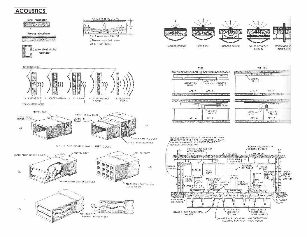

48rdquo
48rdquo
CODES
COMMUNICATION + SIGNALSecurity System Descriptionpassive infrared
motion detector
mechanical motion detector
photoelectric
acoustic
normally closed contact device
- senses rapid change in infrared radiation or heat win zone - used when motion is expected- can be triggered by HVAC systems
- uses microwave or ultrasonic frequencies- doppler effect- lateral movement may be undetected place in line w likely path of travel
- spring mounted contact suspended win another contact surface- requires sensitivity adjustments to avoid false alarms
- triggered by interruption in a laser or infrared beam- can be triggered by dust birds weather etc if outside
- triggered when noise level exceeds preset limit- can be set to respond to frequency of breaking glass
- magnetic strip or spring loaded devices doors amp win-dows- triggered when circuit opened