Embed Size (px)
Citation preview

Sustainable Decentralized Water Treatment
for Rural and Developing Communities
Using Gasifier Biochar

Sustainable Decentralized Water Treatment for Rural and Developing Communities Using Gasifier Biochar
Version 1.0, March 2012
Corresponding author Josh Kearns Director of Science, Aqueous Solutions PhD Candidate, Environmental Engineering Engineering for Developing Communties University of Colorado-Boulder [email protected] Co-authors and contributors Research Advisory Committee: Professors R Scott Summers, Karl Linden, and Fernando Rosario-Ortiz (University of Colorado-Boulder), Detlef Knappe (North Carolina State University), Stephen Joseph (University of New South Wales) Technical advising and analytical support: Professor Gerard Cornelissen (Norwegian Geotechnical Institute), Lisa Lentz (North Carolina State University), Elisabeth Mansfield (National Institute of Standards and Technology, Boulder, CO), Hugh McLaughlin (Alterna Biocarbon), Colleen Rostad and David Rutherford (US Geological Survey), Wanna Sanjaikla (Dusit University, Thailand), Carl Saquing (North Carolina State University), Professor Pakawadee Sutthivaiyakit (Kasetsart University, Thailand) Facilities support: Nathan Bailey (Director Structural Engineering Laboratory) and Sid Gustafson (Director Physics Trades Teaching Laboratory) University of Colorado-Boulder, Chirapong Kuhakanchana (Royal Forestry Department Wood Energy Research Centre, Thailand), Jon Jandai, Nathan Reents and Peggy Reents (Pun Pun Center for Self-Reliance, Thailand) Gasifier cookstove project (CU-Boulder): Professor Bernard Amadei, Mike Barbee, Kristen Matsumura, Boston Nyer, Anna Segur Research and fieldwork support: Mike Barbee, Saw Rocky Khu Bittakah, Damien Bohler, Alexsandra Guerra, Fedde Jorritsma, Ryan Mahoney, Boston Nyer, Rachael Ramsey, Nathan Reents, Kyle Shimabuku, Lauren Wellborn Field-site hosts: Reents family (Jefferson, CO), Ponderosa house (Boulder, CO), Pun Pun Center for Self-Reliance (Thailand), Royal Forestry Department Wood Energy Research Centre (Thailand) Institutional support: Aqueous Solutions, The Department of Civil, Environmental & Architectural Engineering and The Mortenson Center in Engineering for Developing Communities, CU-Boulder, Pun Pun Center for Self-Reliance (Thailand), Royal Forestry Department Wood Energy Research Centre (Thailand) Funding support: University of Colorado Chancellors’ Fellowship, Beverly Sears Graduate Student Grant (CU-Boulder), American Water Scholarship (American Water Works Association), Aqueous Solutions, iBoP-Asia Grants Program (Ateneo School of Government, Philippines, and International Development Research Centre, Canada), National Collegiate Inventors and Innovators Alliance (NCIIA), CU-Boulder Excellence in Engineering Fund, Hach Corporation, The Foundation for Global Community, The Charles A and Anne Morrow Lindbergh Foundation, Rotary Clubs of Statesville, NC, Johnson Memorial United Methodist Church Huntington, WV, private individual donors Editing and helpful comments for this document: Sara Beck, David Kempisty, and Ryan Mahoney (CU-Boulder), Stephen Joseph (University of New South Wales), Rick Burnette (ECHO-Asia) Still photography by Lyse Kong. Schematic illustrations by Nathan Reents.

Contents
Terminology and Abbreviations .................................................................................................. 1 Executive Summary ...................................................................................................................... 2
I. Synthetic Chemical Water Contaminants: An Often Overlooked Challenge in Sustainable Community Development ................................................................................. 3
II. Charcoal/Biochar Filtration: An Appropriate, Low-Cost and Sustainable Option for Decentralized Water Treatment? ......................................................................................... 4
III. Summary and Discussion of Field and Laboratory Research Outcomes .......................... 5
a. Charcoals produced from traditional kiln systems ....................................................... 5 b. Chars produced from biomass gasifiers ........................................................................ 7
IV. Preliminary Conclusions From Laboratory and Field Research .................................... 12
Diagram: 200 L Top-Lit Up-Draft (TLUD) Biomass Gasifier ......................................... 13
V. How-To Section: Fabricating A 200 L Top-Lit Up-Draft (TLUD) Biomass Gasifier For Generating Enhanced Water Filter Biochar ...................................................................... 14 a. Conceptual background ................................................................................................ 14 b. Materials and tools ......................................................................................................... 16 c. Construction ................................................................................................................... 16 d. Operation ........................................................................................................................ 17 e. Optional parameter monitoring and ongoing collaborative gasifier char
research ........................................................................................................................... 20
Diagram: Multi-Barrier Water Treatment System ........................................................ 21
VI. How-To Section: Constructing A Multi-Barrier Water Treatment System Incorporating Biochar Filtration ................................................................................................................. 22 a. Siting and materials ....................................................................................................... 22
i. Siting .................................................................................................................. 22 ii. Containment ...................................................................................................... 22
iii. Plumbing ............................................................................................................ 23 iv. Media .................................................................................................................. 23
b. How it works… (and how to maintain it…) ................................................................ 24 i. Gravel roughing filter ....................................................................................... 24
ii. Slow/bio- sand filter .......................................................................................... 24 iii. Charcoal (biochar) filter .................................................................................. 26 iv. Safe water storage ............................................................................................. 28
VII. Concluding Remarks ............................................................................................................ 29
VIII. References ............................................................................................................................. 30

1
Terminology and Abbreviations Adsorption / Absorption / Sorption “Adsorption” signifies a surface interaction between dissolved species and solid material (in this case, char). This process is distinct from “absorption,” which means “to soak up” or “to take into.” To be exact, however, in water treatment contaminants diffuse into char pores (absorption) where they bind to char surfaces (adsorption). This has led wide use of the nonspecific term “sorption.” Biochar / Charcoal / Char “Biochar” refers to the practice of applying charred biomass to agricultural soils in order to increase crop yields, and/or to sequester carbon in the soil. “Charcoal” refers to a biomass-derived char product most often used as cooking fuel. “Char” is a nonspecific term used for convenience referring to biochar or charcoal. Biomass / Feedstock Here, “biomass” refers to any woody or cellulosic material (e.g. wood, agricultural and forestry residues) that serves as the precursor, or “feedstock,” for making char. Gasifier A device for heating biomass in order to cause it to evolve volatile and flammable gases, which are then combusted to provide energy, typically for cooking or space-heating. Micro-porosity / Surface Area A “micro-porous” material possesses very fine pore structure at the nanometer to micrometer (10-9 – 10-6 m) scale. “Surface area” refers primarily to internal surface area, i.e. within micro-pores. Pathogen Human-disease-causing waterborne microbiological agent. Pyrolysis The process by which char is generated, wherein biomass is heated under restricted oxygen atmosphere. Distinct from combustion (“burning”) wherein biomass is heated with sufficient oxygen present, leaving only ash as the solid residue. 2,4-D 2,4-dichlorophenoxyacetic acid, a prevalent herbicide AC/GAC activated carbon / granular activated carbon BSF / SSF / S-BSF biological sand filter / slow sand filter / slow biological sand filter SOC synthetic organic compound TLUD “top-lit, up-draft” – referring to a mode of operation of biomass gasifier units WASH water-sanitation-hygiene

2
Contamination of drinking water sources by synthetic organic compounds (SOCs – e.g.
pesticides, pharmaceuticals, fuel compounds) is a growing worldwide problem. Many of these chemicals
bio-accumulate in the human body and cause cancer, birth defects and diseases of the reproductive
system, and disrupt endocrine and neurological systems. However, few low-cost, sustainable and
appropriate treatment technologies are available to rural and developing communities for SOC removal.
Moreover, SOCs are rarely or not-at-all addressed in the majority of safe drinking water programs
implemented by major international development NGOs and government agencies, university research
programs, philanthropic organizations, non-profits, faith-based charities, etc.
In advanced centralized water treatment systems, adsorption by activated carbon (AC) is
considered the best available technology for the removal of SOCs. However, the manufacture of AC is a
sophisticated (and often proprietary) industrial process and cannot be replicated at the location and scale
of rural and developing communities. Under these circumstances, charcoals produced by traditional kiln
systems may serve as an effective, low-cost local surrogate for commercial AC as they exhibit similar
molecular-scale properties (e.g. porosity and internal surface area, surface reactive sites). In fact, water
filtration using charcoal is an ancient practice that continues today in non-industrialized regions around
the world, though it has not yet been rigorously demonstrated for removal of modern industrial pollutants.
Unfortunately, charcoal production by traditional kiln systems is often a resource-intensive and
highly polluting process. Moreover, traditional charcoals are manufactured primarily as fuel for cooking
or smelting of ores; kiln processes are typically not optimized for production of water filter char. Low
cost, energy efficient, environmentally sustainable and scalable local production of optimal water filter
char can be accomplished with biomass gasification. Char-producing gasifier stoves are rapidly being
disseminated for household cooking and heating as they provide energy efficient combustion with
reduced emissions. Intermediate- and large-scale gasifier systems are being deployed around the world for
generation of “biochar” as an agricultural soil amendment to increase crop yields and sequester carbon.
The purposes of this document are to (1) summarize preliminary results of collaborative field and
laboratory research pertaining to the use of traditional kiln charcoals and gasifier chars in decentralized
water treatment that targets SOCs, (2) provide a detailed how-to guide for construction and operation of
an intermediate scale (200 L) gasifier char production unit using local materials, and (3) provide a
detailed how-to guide for integration of biochar filtration into a multi-barrier intermediate-scale (2000
L/day) water treatment system constructed from inexpensive and widely available materials.
The information and design specifications presented here are open source / open architecture. We
invite critical feedback from field engineers and WASH (water-sanitation-hygiene) sector development
practitioners, university researchers, sustainable development NGOs, etc.
Executive Summary

3
I. Synthetic Chemical Water Contaminants: An Often Overlooked Challenge in Sustainable
Community Development
Contamination of drinking water sources by harmful synthetic organic compounds (SOCs) such
as pesticides is a major worldwide problem. “Pesticide pollution” appears twice in the top ten of The
World’s Worst Toxic Pollution Problems Report 20111 by the Blacksmith Institute, and has been
indicated every year’s report since initial publication in 2006. Effective, affordable and scalable “green”
treatment technologies for SOC removal that are accessible to communities in the developing world or in
remote areas of developed countries are, however, lacking.
A recent review in Science2 indicates that the 300 million tons of SOCs produced annually,
including 5 million tons of pesticides, constitute a major impairment to water quality on a global scale.
The report highlights particular challenges in developing countries including the overuse of pesticides,
prevalent ignorance of relevant environmental and health hazards, and widespread unauthorized use of
“black market” chemicals. In Thailand, for example, 75% of the pesticides used are banned or heavily
restricted in the West due to deleterious ecological and human health effects.3 The Science authors specify
that “small-scale, household-based removal techniques are often the only possible mitigation strategy due
to the lack of a centralized infrastructure,” and call for the development of “reliable, affordable, and
simple systems that local inhabitants could use with little training.”
Unfortunately, SOCs are not yet “on the radar” of major actors in the water-sanitation-hygiene
(WASH) sector of international development. The UN Millennium Development Goals, for example, are
only concerned with mitigation of biological agents of waterborne disease.4 I recently attended a major
international conference on global water and health in developing communities.5 My presentation was the
only one that considered SOCs in drinking water and presented a potential treatment technology.6
Microbial pathogens are often the most immediate threat to human health (e.g. diarrhea) and so focus on
these disease agents is warranted. However we cannot discount the threat of bio-accumulating chemical
toxins such as pesticides. The immediacy and scale of this problem is highlighted by, for example, a
survey of Hmong tribe women living in Mae Sa Mai village, Chiang Mai Province, Thailand, that
reported detection of DDT in 100% of mothers’ milk samples. A number of other biocides were also
frequently detected, and infants’ exposure exceeded by up to 20 times the acceptable daily intakes as
recommended by UN-FAO and WHO.7

4
II. Charcoal/Biochar Filtration: An Appropriate, Low-Cost and Sustainable Option for
Decentralized Water Treatment?
Charcoal filtration has been used to treat drinking water for thousands of years,8 and is still
widely practiced today – particularly in rural areas of the major charcoal producing countries such as
Brazil, India, China, Thailand, and throughout SE Asia.9 Locally managed charcoal filtration might
represent the most effective barrier to SOC exposure available to households and communities in remote
and impoverished regions of the world, as charcoal can exhibit properties similar to activated carbon.10
To-date, however, no studies have quantified how effective charcoals are for water treatment.11
Scanning election microscope (SEM) images of longan charcoal and commercial activated carbon showing morphological similarities. (Charcoal SEM images courtesy of Carl Saquing, North Carolina State University.)

5
Our research aims to demonstrate the applicability of locally generated traditional charcoals and
gasifier chars for decentralized household and small community water treatment in developing
communities. This work realizes a triple-benefit for human health, environmental sustainability, and local
economies: (1) to offer economical and technologically accessible water treatment where currently none
exists; (2) to offset polluting and energy-inefficient charcoal production with a “green” technology; and
(3) to support village level microenterprise in the manufacture of enhanced sorbents. Through
partnerships with governments, small businesses, and local and international NGOs, we disseminate these
research outcomes in the deployment of appropriate technologies that benefit human livelihoods as well
as the environment.
III. Summary and Discussion of Field and Laboratory Research Outcomes
This section outlines the outcomes of recent field studies and laboratory experiments
investigating the potential effectiveness of traditional kiln charcoals and gasifier chars for water
treatment. To clarify: traditional kiln systems are used to produce charcoals from wood feedstocks
typically for use as cooking fuel. Kilning processes are often highly polluting, energy-inefficient, and
time- and labor-intensive. Energy efficient, clean burning gasifier units that are typically used for cooking
and space-heating produce a residual char, are easier and more pleasant to operate, and make use of a
wider range of biomass feedstocks including agricultural and forestry wastes and by-products. More detail
on the conceptual background of biomass gasification for char production is given in Section V. Also, an
instructional video explaining the conceptual background, construction, and operation of a 200 L drum
gasifier unit can be accessed from the Aqueous Solutions website: www.aqsolutions.org.
a) Charcoals produced from traditional kiln systems
Our preliminary experiments show that some charcoals produced from traditional Asian village
kilns (e.g. the 200 L horizontal drum12 and brick-and-mud beehive models) exhibit appreciable sorption
capacity for herbicides. However, our studies indicate wide variability in SOC uptake among charcoals
produced by traditional technologies.13 Although these initial results are promising, traditional charcoal
manufacture systems are energy inefficient and highly polluting, contributing substantial greenhouse gas
emissions, and often making use of unsustainably, and sometimes illegally, harvested feedstocks.14,15,16
6
!"#$%&'(
#)*+,#"+'#)*-.(
."#&
'(*
/0,#%)#($
1**
233*4*5!..)*$"678#$'
9.*:%)(*
* *9"%+:;#($;76$
*<9.
.,%=.>*:%)(*
* *

7
Herbicide removal by a representative range of simulated traditional kiln charcoals.
When it comes to water treatment, not all traditional charcoals are created equal. We have
monitored traditional charcoal production in 200 L steel drum/adobe kilns and brick-and-mud beehive
kilns in collaboration with farmers and villagers in northern Thailand and the Thai Royal Forestry
Department Wood Energy Research Centre in Saraburi Province. These observations inform simulations
of the typical range of peak temperature and heating duration characteristic of traditional charcoal
production systems using a programmable laboratory pyrolysis unit to generate experimental chars. The
plot above indicates wide variability in herbicide uptake capacity of charcoals produced under a
representative range of conditions. Charcoals exhibited essentially no uptake to ~ 80% removal under
these experimental conditions. (Experimental methods and additional data are presented and discussed
below.) Thus the manufacture conditions and resulting quality of the char product exert a strong influence
on its potential effectiveness for water treatment.
b) Chars produced from biomass gasifiers
Energy efficient, environmentally sustainable and scalable production of consistent highly
sorptive chars can be accomplished with biomass gasification. Biomass gasifier stoves are rapidly being
disseminated for household cooking in developing communities as they provide energy efficient
!"#$
%&#$
&%#$
'#$
&(#$
)#$
!)#$
')#$
%)#$
*)#$
+)#$
,)#$
&)#$
()#$
")#$
!))#$
++)$-./$($012$ &))$-./$($012$ (+)$-./$($012$ %+)$-./$*$3452$,))$-./$%$3452$
061789836$16:;<4=$
>64?$@6:>614@A16$4B3$064CBD$3A14C;B$
6A94=5>@A2$78;9041$E$=47$>51;=5F61$28:A=4C;B2$;G$@1438C;B4=$?8=B8BD$9;B38C;B2$
=47$GA1B496$28:A=4C;B$;G$@1438C;B4=$'))$H$
2@66=$31A:I43;76$?8=B$
=47$GA1B496$28:A=4C;B$;G$@1438C;B4=$7189?J4B3J:A3$
76608<6$?8=B$

8
combustion with reduced emissions,17,18 and produce small batches of char from agricultural and forestry
by-product fuels during normal daily use.19,20 Intermediate and large scale gasifier systems are also being
deployed around the world for generation of “biochar” as an agricultural soil amendment to increase crop
yields and sequester carbon.21,22,23 Gasifier char production is favorable from environmental and energy
standpoints when compared with traditional charcoal manufacture since pyrolysis gases are combusted
within the unit rather than emitted as pollutants,24,25 thereby providing the energy that drives pyrolysis and
obviating the need for an external heat energy source. Also, biomass gasifiers can be readily coupled with
other unit processes for bio-fuel collection and waste heat utilization.26
Cookstove-scale biomass gasifier char production unit. See Anderson et al. 2007,27 Anderson 201028 and McLaughlin 201029 and 201130 for theory and detailed construction notes. (Thermocouple probes are for research purposes and may be omitted.)
Our studies to-date show that gasifier chars, particularly when operated in high-draft mode (for
example, by augmenting airflow when necessary by a fan or blower) consistently develop enhanced
physico-chemical characteristics such as high surface area, micro-porosity, and herbicide uptake capacity
when compared with traditional kiln charcoals.31,32 Gasifier char may therefore be an optimal choice for
!"#$%&&'(%&")*+',-%+'(*.*+%/#.'0,##1&2#3*'&,%4*5'
67(%4'8%".2',%.'+*%,2#+'!#9:'0-#4*&'".'!#;#$5''2-*+$#,#<84*'8+#!*&''&$%44'*4*,2+",'=%.'
&*,#.9%+:'%"+'".'=#+'
,#$!<&/#.'#='8:+#4:&"&'(%&*&'
''''''
8+"$%+:'%"+'9+%>'
!"#$%"&'$
(%!)*++$,#--#.+$ &'*/$,/!01&.$
,-"$.*:'*?*,2'%4#.*@'A.%2<+%4'9+%>B'0CD5'
'
=%.7*.-%.,*9'9+%>@''A=#+,*9'9+%>B'0ED5'

9
sorption of pesticides, industrial and fuel compounds, human and livestock pharmaceuticals, and other
SOCs of increasing concern to water quality.
Plots showing surface area (upper) and porosity (lower) of chars made (1) from split pine logs in a 200 L traditional style steel drum and adobe kiln, (2) from uniform pine wood slats in a programmable laboratory pyrolyzer used to manufacture char under controlled temperature and atmospheric conditions, and (3) from a cookstove scale TLUD gasifier using pine pellets. (Surface area and porosimetry courtesy of David Rutherford, USGS.)
!"!#!$%#
&'%#
&%!#
!%%#
($%#
)#
*)#
'))#
'*)#
!))#
!*)#
&))#
&*)#
())#
(*)#
*))#
+#%*)#,-# **)#,-# $))#,-# .*)#,-# %!*#,-#/012#
"))#,-#/312#
4! 56#
789:#;8478<9;=<8#
>=<?9@8#9<89#A#7BC8#DBE@F9<>#
;<9GBHEC9I#:BIC#I9D#?=<C9@8#7J<EIJK8<# @EE:>;EL8#
69>BM8<#
!"#$% !"#&%!"#'%
!"(#%
!"#)%
!"*(%
!"#+%!"#(%
!"#)%!"#'%
!"#*%
!"(!%
!"!!%
!"!)%
!"#!%
!"#)%
!"(!%
!"()%
!"*!%
!"*)%
,%&)!%-.% ))!%-.% $!!%-.% ')!%-.% &()%-.%/012%
3!!%-.%/412%
5567%
89:;%<9=89>:<?>9%
8@>@AB<C%D%8BE9%FB@5G:>A%
<@<:H%8@>9%I@H?=9%
=B5>@J8@>9%I@H?=9%
<>:KBL@E:H%;BHE%H:F%M?>E:59%8C>@HCN9>% 5@@;A<@I9%
7:ABO9>%

10
Plot showing removal of the common herbicide 2,4-D (2,4-dichlorophenoxyacetic acid) from solution by various chars in batch experiments.
2,4-D was chosen as a test compound because of its environmental relevance as one of the most
widely used herbicides worldwide and one of the most commonly detected pesticides in environmental
waters,33 as well as for its human health implications as a potential carcinogen and suspected endocrine
disruptor.34 Its chemical properties also make it a challenging compound to remove by adsorption – thus
if 2,4-D is taken up by a char then it is likely that most other pesticides would also be effectively
removed.
Batch experiments used 100 mg/L of each char ground by mortar and pestle to pass a 200-mesh
US Standard Sieve, and introduced to solutions initially containing 100 µg/L 2,4-D, and background
organic matter at a total organic carbon concentration of 4 mg/L (to simulate natural waters). Experiment
bottles were agitated for two weeks in order to reach equilibrium. The traditional kiln data is an average
for three chars made from bamboo, split eucalyptus and pine logs charred in a 200 L steel drum/adobe
kiln. The lab pyrolyzer data displayed are an average of four chars made from bamboo, eucalyptus,
longan and pine logs cut into slats of uniform size (15 cm x 10 cm x 1 cm) and pyrolyzed under
controlled temperature and atmospheric conditions. The gasifier data displayed are an average from
several batches of pine pellet char made in a cookstove-scale TLUD unit under natural-draft (“ND”) and
forced-draft (“FD”, with an electric fan) conditions. The gasifier-FD char also removed 2,4-D below
detection limits (4 µg/L) at a dose of only 20 mg/L. Thus as indicated in the plot above, at a dose of 100
!!"#
$%"#
&$"#
!'"#
&("#
)*%%"+#
%"#
*%"#
$%"#
'%"#
(%"#
&%"#
,%"#
!%"#
-%"#
.%"#
*%%"#
/#,&%#01# &&%#01# !%%#01# -&%#01# ,$#
2345#
.%%#01#
2645#
789:;<;=8#98>?@AB#
C8AD#E8>C89AEF98#
$G(H4#789:;<;=8#98>?@AB#:I#:;?<7A9J#
2*%%#>KLM#<7A9#=?J85#
)#*%%"#
E9A=;N?OAB#D;BO#
2:A>:??G#8F<ABICEFJG#C;O85#
BA:#PF9OA<8#CI9?BIQ89#
2:A>:??G#8F<ABICEFJG#
B?OKAOG#C;O85#
<??DJE?@8#KAJ;R89#
2C;O8#C8BB8EJ5#

11
mg/L additional capacity exists in the gasifier-FD char even after all 2,4-D is taken up: hence “>100%”
removal.
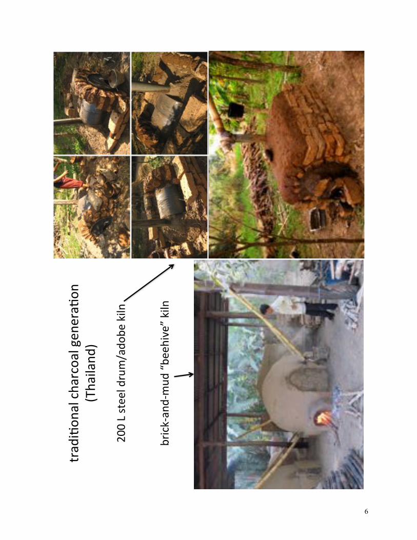
We are currently characterizing chars produced with intermediate-scale gasifiers made from 200
L steel drums (as pictured below) as a means for generating greater quantities of enhanced water filter
char from agricultural and forestry residues.
Gasifier biochar production system made from two 200 L drums and scrap metal. (Photo by Lyse Kong.)

12
IV. Preliminary Conclusions From Laboratory and Field Research
In summary, compared with traditional charcoal production, gasifier char production is more
energy efficient and emits far less atmospheric pollution. Furthermore, gasifiers can be operated with
agricultural and forestry residues and by-products, are ideally suited for small grained, chipped or
pelletized biomass fuels. Gasifiers can readily be linked with other processes and applications for capture
and use of waste heat. Our research has shown both small scale (cookstove) and intermediate scale (200 L
drum) pyrolyzers to consistently achieve high temperatures (650-950 °C) required for substantial
development of surface area and porosity in the char product, concomitant with improved performance
for herbicide uptake in batch experiments. Therefore, gasifier biochars are a promising appropriate, low-
cost and sustainable technology for affordable decentralized water treatment in rural and developing
communities.
Furthermore, the use of biochar for water treatment does not preclude its eventual application as a
beneficial agricultural soil amendment and carbon sequestration strategy. In fact, we recommend
composting35 and soil application as the preferred mode of processing spent filter char. The best strategy
for rural communities and smallholders to utilize spent filter char is simply to allow ample time and
favorable conditions for environmental microorganisms to biodegrade any sorbed contaminants. Elevated
temperatures such as those achieved during composting of organic wastes, for example in composting
toilets, accelerate microbial activity and biodegradation processes. Moreover, based on recent research
with carbon adsorbents we do not expect significant contaminant release to soils and plants by leaching
from spent filter char.36 A conservative approach to land application of spent filter char can also be
adopted, using low incorporation rates of ~ 100 kg of char per hectare.

13
!"#$$"%&'()"*+",&-&."&/"0(123&0",&45"67".."8#9:;<"
7"2."'*="*+"3&="&/"0(123&0",&45"
>$"2."
?#"2."
?$"2."
>$"2."
?7"2."
2%*.+(5"
20&@+"
0(123&0",&45"
3(.=(013A0("=0&,("%&A)*+B"8&=C&+1'<"
%1+4'("
'*4D"77"2."
>$$"E"F&=GE*3"H=GI01J"8FEHI<"K*&.1))"L1)*M(0"
"
N&0"L(+(01C+B"O+%1+2(4"P13(0"N*'3(0"K*&2%10"
)3A045")A==&03"
?>$"2."
>7"2."

14
V. How-To Section: Fabricating A 200 L Top-Lit Up-Draft (TLUD) Biomass Gasifier For
Generating Enhanced Water Filter Biochar
An instructional video explaining the conceptual background, construction, and operation of this
unit can be accessed from the Aqueous Solutions website: www.aqsolutions.org.
a) Conceptual background
The process of creating char from biomass – pyrolysis – involves heating the woody starting
material (“feedstock”) in an oxygen-restricted environment. The key to generating enhanced water filter
biochar (i.e. char with substantial micro-porosity and surface area for the effective uptake and binding of
synthetic organic pollutants) is reaching hot enough temperatures to remove the naturally occurring tarry
and oily components of biomass while converting the remaining carbon-rich material to a graphite-like
structure. In biomass gasification, high temperatures are obtained by ensuring a strong air draft through
the feedstock. A strong draft supplies oxygen for a small amount of the feedstock to combust thereby
providing heat to gasify and carbonize the adjacent remaining feed. The draft also sweeps the tarry and
oily vapors away from the carbonizing feedstock, which allows for the development of extensive porosity
in the char.
In a top-lit up-draft (TLUD) gasifier, air draft enters through holes in the bottom of the reactor
body and rises upwards through the feedstock (“up-draft”). The fire burns from the top of the reactor body
downward (“top-lit”). (See schematic below.) The zone of pyrolysis thus moves from the top to the
bottom of the reactor body over the course of the burn. The upward-moving air draft (termed “primary
air”) supplies limited oxygen to keep the process going but not enough to combust all of the hot
feedstock. As primary air draft moves through the pyrolysis zone within the reactor body it sweeps
combustible gases rapidly upwards into the combustion zone within the crown and chimney. Vents in the
crown admit ample air (termed “secondary air”) for complete combustion of the hot pyrolysis gases. The
hot combusting gases move upwards through the chimney, augmenting the primary air entering the
bottom of the reactor body.

15
Schematic of TLUD gasifier interior showing feedstock gasification/carbonization in the heating zone and combustion of the rising pyrolysis gases when combined with secondary air in the combustion zone. The heating/pyrolysis zone proceeds from the top to the bottom of the reactor body during firing. (Illustration by Nathan Reents.)
A well-operating TLUD gasifier should emit little or no smoke, since the vapors and particulates
that constitute smoke are completely combusted within the unit. This is what makes the process more
energy efficient and environmentally friendly than traditional charcoal manufacture. In traditional
charcoaling, pyrolysis gases – which include methane, carbon monoxide, nitrogen oxides, particulate
matter, and other products of incomplete combustion – are released in large quantities as problematic air
pollutants. Furthermore, in traditional charcoaling a separate fuel source in addition to the feedstock is
required to provide the heat energy for pyrolysis. TLUD gasifiers solve both of these problems

16
simultaneously by completely burning the pyrolysis gases, releasing primarily only CO2 and water vapor
to the atmosphere, while powering the conversion of the feedstock stock to char. Moreover, gasifiers are
less time-consuming to operate: the burn period of a traditional-style 200 L steel drum kiln is typically 5-
8 hours with a 12-hour cooling period; the 200 L TLUD gasifier burns for 1-2 hours depending on the
feedstock, and takes another 1-2 hours to cool to handling temperatures.
b) Materials and tools
Note that the TLUD gasifier design described here is an open architecture – feel free to modify as
needed to achieve desired performance. We invite your feedback on the construction and use of this and
similar units. Please send comments to [email protected].
Materials required include: two 200 L (55 gal) steel drums for the reactor body, crown and lid;
scrap metal (square tubular or angle iron) for handles; sheet metal or flue pipe for chimney (NOT tin,
aluminum, or thin galvanized steel as these will melt or quickly break down); concrete block or similar to
form a study support base; assorted bolts, nuts and washers. Helpful tools include an angle grinder and
drill/bits or cold chisel for cutting metal, and a basic welding setup.
c) Construction
Drum #1 will become the reactor body and drum #2 will become the crown and lid.
Cut a circle out of the top of drum #1 leaving a 5 cm lip around the edge. Drill about 300 evenly
spaced holes 9-10 mm in diameter (3/8”) in the bottom of drum #1. Alternately, cut radial slots into the
bottom of the drum giving a similar total cross-sectional area of openings. Cut some pieces of angle iron
or square tubular steel at least 120 cm long for handles. Weld or bolt these securely to the sides of drum
#1.
If you don’t have ready access to flue pipe, the chimney can be fabricated by rolling a rectangular
piece of sheet steel, then clamping and welding the seam.
Cut the upper and lower triangular vents evenly spaced around one end of drum #2: four upper
vents 15x20 cm and four lower vents 10x13 cm offset from the upper vents (see diagram at the beginning
of this section). Then cut around the perimeter of drum #2 to make the crown 25 cm tall. Cut a tabbed

17
opening in the center of the crown face, bend the tabs outward and attach the chimney by bolts or welds.
Cut the lid out of the other end of drum #2 – about 55 cm in diameter, or large enough to overlap the lip
cut in the top of drum #1 by 2-3 cm while still fitting inside the rim.
Cut two 2 m lengths of angle iron or metal tubing to use for removing the hot crown.
Place the reactor body onto concrete blocks or other sturdy support allowing an ample gap with
the ground for airflow to the bottom of the drum. Place the crown/chimney on top of the reactor body,
with the crown resting on the lip in the top of the reactor body inside the rim of the drum. A snug fit is
good. Make sure everything is level, sturdy, and will not tip over during operation.
d) Operation
For best results making TLUD gasifier char, draft must be optimized. Too much draft results in
high temperatures but too much combustion of the feedstock and thus low char yields. Too little draft
results in insufficient temperatures for the onset of effective gasification – the feedstock smolders,
produces a lot of smoke, and does not char well.
Draft is directly influenced by how the feedstock packs into the reactor body. This depends on the
size and shape of the feedstock. Ideal materials are dry (not freshly cut) wood branches and bamboo poles
2-5 cm in diameter cut to 10-15 cm lengths. Corncobs are a good size and shape. Smaller branches and
twigs, small lumber scrap, chipped and broken coconut shells, and coarse wood chips can also be used.
Biomass pellets work well if they are not too small. Small pellets, fine wood chips, rice husks, saw dust
and wood shavings are too fine and inhibit draft unless a supplemental fan or blower is applied to enhance
primary air supply. Thick materials can be used but need to be thinly cut – whole logs do not char
thoroughly. Mixtures of different materials, sizes and shapes, work fine.
The best water filter char comes from woody feedstocks with high lignin content. Switchgrass,
straw, and rice husks are mainly composed of cellulose and mineral matter and do not produce good water
filter char. Corncobs produce mediocre water filter char and do not require processing (i.e. cutting or
chipping) prior to loading into the reactor.
Place the reactor on the concrete block supports and load it uniformly with cut or chipped
feedstock. If using dense wood as the primary feedstock, a 5-10 cm layer of chopped bamboo or corncobs
can be loaded into the top portion of the reactor body to accelerate the initial heating and gasifying of the
wood. Set the crown/chimney firmly in place and stuff a few handfuls of straw inside the crown as

18
kindling. (Accelerants such as kerosene or lighter fluid are not necessary and should be avoided.) If there
are any air gaps where the chimney is attached to the crown seal them with mud.
Light the straw through the vent holes of the crown. The material at the top of the reactor body
will begin to burn. A small amount of smoke may be emitted from the chimney during this stage. Once
sufficient temperatures have been attained for gasification, the feedstock glows while a yellow-orange
“fireball” should appear hovering near the top of the reactor body, inside the crown and inside the lower
chimney. In preparation for shutdown, make a mud pit adjacent to the reactor body large enough to
readily accommodate the drum, and save an additional 1-2 buckets of mud for sealing the top of the
reactor.
A candle or chunk of wax can be rubbed on the outside of the reactor body to indicate where the
pyrolysis zone is located. When the pyrolysis zone reaches the bottom of the reactor body a red glow will
be visible through the primary air holes. The yellow-orange color of the “fireball” in the crown will fade
to a clear, bluish flame. This indicates that all wood gases have been burned off from the feedstock and
char combustion is commencing. Char combustion occurs at much higher temperatures than gasification
(in excess of 1400 °C compared with 700-900 °C typical for gasification). It’s undesirable to let char
combustion continue for too long since the desired char product is being destroyed, and because the very
high temperatures may result in the structural failure of the reactor body. The appearance of a blue flame
along with the fading of the yellow-orange flame is thus a dependable visual indicator of when it’s time to
shut down the process.
Shutting down the gasifier requires two persons. (See photo series below.) Wear study leather
work gloves. Place the 2 m lengths of metal tubing or angle iron through the vent holes in the crown to
act as handles. With a person on opposite sides of the gasifier, lift off the crown/chimney and set it aside.
Place the lid on top of the reactor body, then grasp the handles of the reactor body, lift and set it in the
adjacent mud pit to seal the bottom. Use the mud set aside to seal the lid on the top of the reactor body.
Allow the reactor to cool at least 1-2 hours, then remove the mud and collect your biochar!
[Note: An alternative shutdown method involves dousing the hot reactor and contents with
copious water. This may alter the sorption properties of the product char in favorable or unfavorable
ways. We are currently investigating the effects of “wet shutdown” on char properties and cannot
recommend for or against this procedure at this time.]
During the charring process the feedstock sinks, subsides, and shifts in the reactor – for making
optimal water filter char it is normal and desirable for the volume to have shrunk to one-half or even one-
third of the drum.

19
Photo series showing shutdown procedure: When bottom of drum begins to glow (a) and blue flames appear in crown (b) then pyrolysis is nearing completion. Remove the crown and chimney (c) and (d). Put on the lid and move the reactor body to the adjacent mud pit to seal the bottom (e) and (f). Seal the top with mud to prevent air leaks (g) and (h). (Photography by Lyse Kong.)
!"#$ !%#$
!&#$ !'#$
!(#$ !)#$
!*#$ !+#$

20
e) Optional parameter monitoring and ongoing collaborative gasifier char research
Those who desire a more in-depth experience in making consistent and optimal water filter char
can monitor temperature and mass loss during their process. These parameters provide a ready indication
of how extensively carbonized and porous the product char is, and how consistent the process is from one
batch to the next.
Thermocouple probes positioned inside the reactor body can be protectively housed in a simple
manifold made from threaded steel plumbing nipples and connectors. Temperature dataloggers greatly
facilitate data collection during the heating phase. Comparing the mass of the product char to the original
mass of the feedstock gives an estimate of the extent of conversion – a well-carbonized char undergoes
greater mass loss than a poorly carbonized char. Using the model of TLUD gasifier depicted here we have
consistently achieved peak temperatures of 750-950 °C for burn durations of 1-2 hours (depending on the
type of feedstock), with corresponding mass losses around 85% (a full drum yields 1/3-1/2 drum by
volume; or, a 40-75 kg batch of feedstock yields 6-12 kg of char by mass). These conditions are optimal
for generation of good quality water filter char.
Temperature data collected from several runs with our gasifier using a variety of feedstocks.
Biochar experimenters who track these parameters are encouraged to submit their data and
observations to our open-source database. Contact [email protected] to find out more.
!"
#!!"
$!!"
%!!"
&!!"
'!!"
(!!"
)!!"
*!!"
+!!"
#!!!"
!,!" !,'" #,!" #,'" $,!" $,'" %,!"
-./0.
12-31."4567"
8.29:;"<3129=:"48=31>7"
$!!"?"@A=/2>>";2>AB.1"
C.3D2.:2".3D2CE0-3>"@2/@=="D=1:D=@>"
/AF.<"/2-.1A2C>"

21
!"#$%&'(
"%)*!+,-'&)./#&'(
+")!")/+01#$,-)
23/(1*'&&!$&)0
'#$&)#&$'#2
$"#)454#$24)
67)
!"#$%&#'&(%
)#*+,#-./*'(#0"
1$%&#'&(-%
12!"
,%34#&('%
4"13.503%6'$(
4%
-'",
/)5"7%
-#08
%6'$(
4%
*.#4*"#'%
9)5"*.#4:%6
'$(4%
$4(#$(8%
,#$(4%
-$"4#3(%
;<=%>%
?%>%
!//34#&'(
+")*5)8'#-'")9$
$"#4)
.#44",
503%&#'&(%
?%>%

22
VI. How-To Section: Constructing A Multi-Barrier Water Treatment System Incorporating Biochar
Filtration
Improving water quality involves mitigating disease causing biological agents (pathogens) as well
as harmful chemical contaminants and non-harmful compounds that impart an unpleasant taste, odor, or
appearance. Pictured above is a multi-barrier water treatment system that addresses these challenges using
a sequence of gravel, sand, and char filtration. A system built according to these specifications can
provide 1500-2000 L/day of treated water depending upon source water quality.
This water system is an open architecture – we invite and encourage modification, adaptation
and improvement! Please share your feedback with [email protected].
a) Siting and materials
i. Siting
Gravity is the easiest and most dependable way to move water. Ideally, the water system is sited
at lower elevation than the source water and higher elevation than the location(s) where treated water will
be used. This circumstance enables completely passive operation of the treatment system and very simple
control using only a float valve (the same device that refills the tanks of flush toilets): when water is
withdrawn from the storage tank the water level in the system drops, opening the float valve. When the
system is full, the float valve closes.
ii. Containment
In SE Asia, stackable prefabricated concrete rings are inexpensive and widely available in most
rural areas and are commonly used for tank construction. Rings are mortared together with concrete and
the tank interior walls sealed with cement slurry. Filling the tank with water when the slurry is still wet
pushes it into pores to cure and seals the tank.
Plastic tanks can also be used, or, if appropriately skilled masons are available, custom ferro-
cement tanks can be constructed. Tanks need to have a large opening and removable lid so that a person
can fully enter for connecting plumbing, installing filter media, conducting routine maintenance (which
includes cleaning tank interiors and removal/replacement of the char), and for repairs.

23
Lids or some cover material to exclude sunlight should be used to inhibit the growth of
photosynthetic microorganisms (algae, cyanobacteria) in the system. Tank tops should be wrapped in fine
mesh screening to prevent entrance of insects, bird droppings, leaves and bits of debris, etc. into the
system.
Tanks should be constructed on a solid and level foundation (preferably of reinforced concrete),
and distinguished from other similar-appearing water tanks (e.g. rainwater, irrigation water, septic, etc.)
using appropriate and durable local signage.
iii. Plumbing
PVC pipe is ubiquitous and cheap in most locations. 1/2” to 3/4” diameter is fine for most
connections to and from the water system and between the tanks. The cleanout valves at the bottoms of
the tanks should be larger, typically 3” to 4”. 1” to 2” is ideal for the harrowing valve midway up the sand
filter tank.
Plumbing in the bottom of filter tanks should be protected from physical damage and blockage by
underdrains made from rock and coarse gravel at least 20 cm in depth. Sand and char filter media should
be supported by an additional graded underdrain made from pea gravel overlain by coarse sand (at least
10 cm deep of each).
The connection from the gravel filter to the sand filter should be located near the top of the tanks,
a few cm below the full-position water line (set by adjustment of the float valve). The connection from
the sand filter to the char filter should enter the char tank at a level about 5 cm above the level of the sand.
(I.e. at a height of about 145 cm above the bottom of the tank if a 40 cm underdrain is used with 1 m of
filter media). The same is true for the connection from the char filter to the storage tank. This ensures that
the water level in the sand and char filters will never drop below the level of the filter media. This is
essential for maintaining full vigor and functioning of the biofilm in the sand filter, and for utilizing all of
the sorption capacity of the char filter.
iv. Media
Standard gravel (1-4 cm sized rocks) is fine for the roughing filter. Standard fine sand (as
opposed to coarse or very fine sand) should be used for the sand filter. Sifted sand or masonry sand are
very fine and may generate too much head loss, especially if source water contains a lot of organic matter.
Large pieces of charcoal should be broken into 1-5 cm pieces. Gasifier char can be used directly since
feedstocks are small or pre-cut materials.

24
b) How it works… (and how to maintain it…)
i. Gravel roughing filter
Source water (controlled by the float valve) enters by a pipe at the bottom of the gravel filter and
flows upward through the media. This removes turbidity (particles) and some dissolved matter that sticks
to the surfaces of particles as they settle. One or more times during the year (depending upon source water
quality), the large valve (at least 3” – bigger is better) at the bottom of the gravel filter is opened, rapidly
reversing the direction of flow through the filter (“backwashing”) in order to flush out the accumulated
sediment and organic matter.
Gravel filter maintenance: As long as the plumbing does not break, or the plumbing or media
become irremediably clogged by sediment or debris, the gravel does not need to be removed or replaced
within the lifetime of the treatment system. Some “MacGyvering” may be necessary to ensure that the
outlet of the float valve completely directs influent water into the pipe leading to the bottom of the tank.
The float valve should be periodically examined for potential clogging or misdirection of influent water.
ii. Slow/bio- sand filter
Sand filters remove microorganisms and particles by physical straining, and some dissolved
compounds by adsorption onto the surfaces of sand grains. Most importantly, however, biologically
active sand filters remove problematic microorganisms and chemical compounds by biodegradation.
Unless a disinfectant such as chlorine is added to the system, a biofilm (or schmutzdecke) naturally
develops within a few days upon beginning use of the filter, and continues to mature over a period of
several weeks. The length of this time period, termed “ripening,” depends primarily upon ambient
temperature and source water characteristics.
The biofilm is concentrated in the top 1 to 3 cm of the media (though exists more sparsely
throughout the sand bed) and actively degrades dissolved organic compounds in the influent water. The
natural environmental microorganisms that comprise the biofilm prevent the establishment of microbial
pathogen colonies through competition and predation. Thus sand filters with healthy established biofilms
are an effective and well-demonstrated technique for removal of pathogens as well as some hazardous
biodegradable compounds in water treatment. An excellent recent compilation of the scientific literature
on micro-pollutant removal through biologically enhanced filtration processes is provided by Shimabuku
et al. 2011.37

25
A note on BSFs and SSFs and S-BSFs… Readers may be familiar with smaller (family sized)
rapid rate “BioSand Filter (BSF)” units promoted for household water treatment in developing
communities, as well as conventional large-scale slow sand filters (SSF) used by municipal drinking
water utilities in developed areas. The slow/bio- sand (S-BSF) filter presented here is an intermediate
design adapted to address some of the respective limitations of BSFs and SSFs.
In short, in sand filters a longer contact time between the water and sand/biofilm provides better
treatment by allowing more time for adsorption and biodegradation mechanisms to occur. However,
increasing contact time requires a larger filter unit to treat a similar volume of water, incurring greater
construction costs and occupying a larger “footprint” for the treatment system. Furthermore, a slow and
steady loading rate (as opposed to a rapid, intermittent loading rate as in household BSFs) contributes to
better biofilm function and enhanced treatment as this establishes a quasi-steady-state influx of nutrients
to the biofilm.
The S-BSF unit process described here combines a low and more consistent loading rate for
optimal contact time with the biofilm and media to achieve effective pathogen removal and contaminant
biodegradation, while providing sufficient total throughput of treated water in an economical, small-
footprint design.
Slow/bio-sand filter maintenance: The sand filter is the “bottleneck” step (i.e. the flow-rate-
determining step) of this water system. As organic material accumulates in the biofilm zone at the top of
the sand bed, flow rates may diminish below a minimum threshold of treated water needed by the
community. Thus a few times per year it may be necessary to “wet harrow” the sand filter to restore
sufficient flow rates. This is accomplished using a long pole to vigorously stir up and suspend the
accumulated sediment from the top few centimeters of sand into the water above the filter bed. The
harrowing valve (located 5 to 10 cm above the top level of the sand) is then opened to allow the
suspended sediment and organic material to wash rapidly out of the upper portion of the tank. The
majority of the suspended sand particles are not washed out but resettle, and the biofilm reestablishes full
function within a few days. (Some sand is washed out during harrowing and after many cycles it may be
necessary to replace some sand to the top of the filter bed.)
The frequency of wet harrowing required to maintain adequate flow rates is determined by the
community’s water needs and the characteristics of the source water. Since the sand filter is the
“bottleneck step” of the treatment system, increased throughput can be achieved by increasing the size
(cross-sectional area) of the filter in the original design, or by building additional units in parallel.

26
iii. Charcoal (biochar) filter
Terminology and key concepts The char filter functions primarily by the process of adsorption.
Adsorption, which signifies a surface interaction between dissolved species and the char, is distinct from
absorption, which essentially means “to soak up” or “to take into.” To be exact, however, in water
treatment contaminants diffuse into char pores (absorption) where they bind to char surfaces (adsorption).
This has led wide use of the nonspecific term “sorption.”
The porosity and large surface area of chars provides a multitude of reactive sites for the
attachment of dissolved compounds. These reactive sites can bind non-problematic dissolved organic
compounds as well as targeted hazardous contaminants. Background dissolved organic matter, present in
all natural waters, can occupy sites on char surfaces and thereby exclude contaminants of concern. This is
called “fouling.”
Fouling in char filters is mitigated by upstream unit processes – in our case, the gravel and sand
filters – that act to remove a substantial portion of background dissolved organic matter from the source
water before it encounters the char. The principle is to achieve a high level of treatment prior to the char
filter, in order to “save the carbon” for removal of targeted problematic dissolved compounds that make it
through the previous treatment steps.
Local chars versus activated carbon In treatment system described here, the char filter functions as a
“post-filter adsorber,” analogous to the use of granular activated carbon (GAC) unit processes in
advanced municipal water treatment facilities. The char filter is placed after the gravel and sand filters in
order to target specific components of background organic matter (for example, compounds that cause
undesirable tastes, odors, or appearance) or SOCs such as pesticides, pharmaceuticals, fuel compounds,
etc., that are not well removed by the preceding unit processes. Knappe 200638 and Summers et al. 201139
provide thorough reviews of the use of GAC in water treatment – the scientific theory and engineering
principles described by the authors apply here as well.
There are, however, a few important differences between locally generated charcoals/biochars
and commercial activated carbon. First, local chars are (ideally) made from agricultural and forestry
residues and sustainably harvested renewable woody biomass. Most commercial activated carbons are
made from (nonrenewable) subbituminous and lignite coal. Both local chars and activated carbons
undergo a carbonization step where the feedstock is heated to several hundred degrees Celsius under
restricted oxygen atmosphere. However, commercial carbons are subsequently “activated” by physical
and/or chemical processes to develop the internal pore structure and surface reactivity using high-pressure

27
steam, CO2, or acids. In other words, the activation step is an industrial process requiring facilities, power,
equipment and reagents that are not accessible in developing communities.
Furthermore, compared with activated carbon, local chars may contain substantial proportions of
residual incompletely carbonized tarry and oily compounds, particularly if the char is generated at lower
temperature (i.e. below ~ 600 °C, as in cooking charcoal manufacture). Local chars may also contain a
high proportion of ash if the feedstock consisted of high mineral content grasses or husks (e.g. rice hulls).
Since local chars are not “activated” and may contain higher proportions of ash or residual tars and oils,
they are not expected to exhibit the same water treatment capacity as commercial/industrial GACs. This
disparity is compensated by designing for higher carbon use-rates (i.e. the mass of carbon used to treat a
given volume of water).
Carbon bio-filtration In the char filter as in the sand filter, if no disinfectant is added to the
system then a natural biofilm readily develops on the surfaces of the filter media. This is generally a good
thing. While the biofilm adds to the influx of natural organic matter in the system and thus may contribute
to fouling, the environmental microorganisms making up the biofilm prevent the development of
pathogen colonies in the media through competition and predation.
Furthermore, recent research on biological activated carbon filters has shown synergism between
adsorption and biodegradation mechanisms for enhanced removal of SOCs.40 The efficiency of the
combined adsorption-biodegradation process is higher than either adsorption or biodegradation processes
alone. Adsorption by the carbon attenuates dissolved contaminants allowing time for their breakdown by
the biofilm, which in turn frees up surface sites on the carbon for additional sorption, extending the life of
the filter media.41 Even some compounds typically classified as non-biodegradable are broken down in
long-running carbon bio-filters. Exposure to contaminants retained by the carbon over periods of weeks to
months allows microorganisms to acclimate and develop the enzymatic pathways necessary to break
down some otherwise environmentally recalcitrant compounds. 42 Thus the synergy between adsorption
and biodegradation processes can result in a net elimination of some hazardous SOCs from the system.
Contaminant leaching and spent carbon processing An often-raised concern for carbon
filtration is the back-diffusion, or “leaching,” of contaminants out of the carbon, either during its lifetime
in the filter bed or afterwards during the disposal phase. Recent research on activated carbon systems has
shown very little leaching to occur.43 Rates of back-diffusion (contaminants being released from surfaces
and exiting through pores) are very slow due to pore blockage by natural organic matter. Essentially,
contaminants diffuse into pores, attach to pore interior surfaces, and are trapped there by incoming natural
organic matter that blocks pores over the operational lifetime of the filter. Moreover, most synthetic

28
organic contaminants bind more strongly to carbon surfaces than dissolved background natural organic
matter – so natural organic compounds are unlikely to displace adsorbed contaminants.
This suggests that the release of adsorbed contaminants from char should not be a great concern,
either during the “use phase” in the char filter or subsequently in the “disposal” phase. As indicated in
bio-filtration studies, time and the metabolic activity of microorganisms are the most effective means for
breaking down sorbed contaminants. In the rural or developing community context, this can be
accomplished through composting the spent filter char and then applying it to agricultural soils in the
manner advocated by biochar practitioners. A conservative approach to land application of spent filter
char can also be adopted, using low incorporation rates of ~ 100 kg of char per hectare.
Char filter refurbishment The effective lifetime of the char filter media depends upon the quality of
the char, as well as the characteristics of the source water and efficacy of upstream treatment steps. In the
rural developing community context, these factors are typified by high degrees of variability and
uncertainty. Since char can be generated locally and inexpensively a conservative approach is
recommended, designing for a much larger carbon use-rate than is employed in advanced GAC systems.
A char filter built according to the specifications outlined here and supplying 2000 L/day should be
refurbished at least every 2-3 years.
This estimate should be taken as a rough guideline. Ongoing research at Aqueous Solutions and
with our collaborators is refining filter system design specifications and recommended operation
protocols. However, it is ultimately up to the discretion of the community and water system operator(s) to
consider factors such as variability in community water demands and seasonal source water quality
concerns (e.g. turbidity and dissolved organic matter increase during the rainy season, local agricultural
cycles and pesticide application periods, nearby industrial development that may impact source water,
etc.) in determining an appropriate char filter bed lifetime and change-out frequency for each installation.
iv. Safe water storage
The storage tank should be sized to meet the water needs of the community with an appropriate
buffer. Great caution must be exercised to ensure that treated water is not re-contaminated during storage,
in the distribution system, or in water receptacles such as jerrycans used by community members.

29
VII. Concluding Remarks
This document summarizes our efforts to-date to evaluate traditional, local and sustainable
decentralized water treatment technologies for the potential to mitigate human health impacts associated
with pesticides and other synthetic industrial water contaminants. Here we present a simple system for the
generation of enhanced water filter char using local materials, and the steps to integrating char filtration in
multi-barrier household and small community water treatment systems.
A companion instructional video explaining the conceptual background, construction, and
operation of the 200 L drum gasifier can also be accessed from the Aqueous Solutions website:
www.aqsolutions.org.
Everything presented here and in the video is considered open source / open architecture, and is
made available free-of-charge to concerned researchers and practitioners in the water-sanitation-hygiene
(WASH) sector of sustainable domestic and international development. Through broad web-based
promotion of these materials we hope to stimulate conversation about appropriate technologies targeting
chemical water contaminants, and to invite criticism, modification, adaptation, improvement and
advancement of the related science and engineering design.
This work is part of our mission as a consortium of research scientists, field engineers, and
ecological designers working to promote livelihood security, environmental and economic sustainability,
and local self-reliance through ecological design and appropriate WASH technologies, in particular
serving rural/remote, indigenous, and politically and economically marginalized communities in SE Asia.
Learn more about our efforts and how you can get involved at www.aqsolutions.org.

30
VIII. References
!!!!!!!!!!!!!!!!!!!!!!!!!!!!!!!!!!!!!!!!!!!!!!!!!!!!!!!!1 Harris J and McCartor A. The World’s Worst Toxic Pollution Problems Report 2011: The Top Ten of the Toxic Twenty. Blacksmith Institute, 2011. (http://www.worstpolluted.org/) 2 Schwarzenbach RP, BI Escher, Fenner K, Hofstetter TB, Annette Johnson CA, von Gunten U, Wehrli B. 2006.
The Challenge of Micropollutants in Aquatic Systems, Science, Vol. 313, p. 1072. 3 PAN-NA. Pesticide Use in Thailand. Pesticide Action Network North America Updates Service (PANUPS).
Pesticides News, March 1997. Accessed online 03/21/07. http://www.panna.org/panna/. 4 World Health Organization and UNICEF 2010, Progress on Sanitation and Drinking Water, 2010 Update. 5 http://whconference.unc.edu/index.cfm 6 Kearns JP, Nyer B, Mansfield E, McLaughlin H, Rutherford D, Knappe DRU, Summers RS. Top-Lit Up-Draft
(TLUD) Cookstove Biochar: Appropriate Technology for Sustainable Low-Cost Household Clean Energy, Water Treatment, Agronomic Enhancement, and Distributed CO2 Sequestration. Poster presentation at Global Water and Heath Conference, University of North Carolina, Chapel Hill, NC October 2011.
7 Stuetz W, Prapamontol T, Erhardt JG, Classen HG. Organochlorine pesticide residues in human milk of a Hmong hill tribe living in Northern Thailand. The Science of the Total Environment 273, 2001. p. 53.
8 “It is good to keep water in copper vessels, to expose it to sunlight, and filter through charcoal.” Translation by FE Place of the Sanskrit Ousruta Sanghita, written c.a. 2000 B.C.
9 United Nations Energy Statistics Database, United Nations Statistics Division, http://data.un.org/Browse.aspx?d=EDATA, accessed 11/5/2011.
10 Chen J, Zhu D, Sun C. 2007. Effect of heavy metals on the sorption of hydrophobic organic compounds to wood charcoal. Environmental Science & Technology, 41(7), 2536–2541.
11 Thus this is a major objective of our research at Aqueous Solutions (www.aqsolutions.org) and the subject of Josh Kearns’ Doctoral Dissertation in Environmental Engineering / Engineering for Developing Communities at the University of Colorado-Boulder.
12 Burnette R. Charcoal production in 200-liter horizontal drum kilns. ECHO Asia Notes No. 7, October 2010. Hugill, B. Biochar – An organic house for soil microbes. ECHO Asia Notes No. 9, April 2011.
13 Kearns JP, Wellborn LS, Summers RS, Knappe DRU. Removal of 2,4-D herbicide from water by indigenous charcoal carbons (biochar). Submitted to Journal of Water and Health (in review).
14 Smith, K. R., Pennise, D. M., Khummongkol, P., Chaiwong, V., Ritgeen, K., Zhang, J., Panyathanya, W., Rasmussen, R. A., & Khalil, M. A. K. 1999 Greenhouse Gases from Small-Scale Combustion Devices in Developing Countries: Charcoal-Making Kilns in Thailand; Report EPA-600/R-99-109; Office of Air and Radiation and Policy and Program Evaluation Division, U.S. Environmental Protection Agency: Washington, DC.
15 Foley, G. 1986 Charcoal Making in Developing Countries. Earthscan: London. 16 UNDP, UNEP. 2009. Bio-Carbon Opportunities in Eastern and Southern Africa: Harnessing Carbon Finance to
Promote Sustainable Forestry, Agro-Forestry and Bio-Energy. 17 Grieshop AP, Marshall JD, Kandlikar M. 2011. Health and climate benefits of cookstove replacement options.
Energy Policy, 2011. 18 Johnson M, Lam N, Brant S, Gray C, Pennise D. 2011. Modeling indoor air pollution from cookstove emissions in
developing countries using a Monte Carlo single-box model. Atmosphereic Environment, Vol. 45, Issue 19, p. 3237.
19 International Biochar Initiative, 2011. http://www.biochar-international.org/technology/stoves, accessed 11/5/2011.
20 Inyenyeri Rwandan Social Benefit Company, http://inyenyeri.org/business-model, accessed 11/5/2011. 21 Lehmann, J., Gaunt, J., Rondon, M., 2006. Bio-char sequestration in terrestrial ecosystems – a review. Mitig.
Adapt. Strateg. Glob. Change 11, 395–419. 22 Bracmort KS (2009) Biochar: examination of an emerging concept to mitigate climate change. Congressional
Research Service. 7-5700, CRS Report No. R40186. Available at: http://ncseonline.org/NLE/CRs/abstract.cfm?NLEid=2216
23 UNDP, UNEP 2009, op. cit. 24 UNDP, UNEP 2009, op. cit. 25 Grieshop et al. 2011, op. cit. 26 Biochar for Environmental Management: Science and Technology. 2009. Lehmann J and Joseph S, eds.
Earthscan, UK & USA.

31
!!!!!!!!!!!!!!!!!!!!!!!!!!!!!!!!!!!!!!!!!!!!!!!!!!!!!!!!!!!!!!!!!!!!!!!!!!!!!!!!!!!!!!!!!!!!!!!!!!!!!!!!!!!!!!!!!!!!!!!!!!!!!!!!!!!!!!!!!!!!!!!!!!!!!!!!!!!!!!!!!!!!!!!!!!!!!!!!!!!27 Anderson PS, Reed TB, Wever PW. Micro-gasification: What it is and why it works. Boiling Point, No. 53,
HEDON Energy Network, 2007. [http://www.hedon.info/docs/BP53-Anderson-14.pdf] 28 Anderson P. Making biochar in small gasifier cookstoves and heaters. Chapter 11 in The Biochar Revolution:
Transforming Agriculture & Environment, P. Taylor ed. 2010. 29 McLaughlin H. 1G Toucan for Biochar – January 2010. Bioenergy Lists web archive.
[http://biochar.bioenergylists.org/content/1g-toucan-tlud-biochar-jan-2010] 30 McLaughlin H. How to make high and low adsorption biochars for small research studies. Bioenergy Lists web
archive. [http://biochar.bioenergylists.org/content/how-make-high-and-low-adsorption-biochars] 31 Kearns JP, Shimabuku K, Wellborn LS, Knappe DRU, Summers RS. Biochar production for use as low-cost
adsorbents: Applications in drinking water treatment serving developing communities. Presentation to 242nd national meeting of the American Chemical Society, Denver, CO, August 2011.
32 Kearns JP, Nyer B, Mansfield E, McLaughlin H, Rutherford D, Knappe D, Summers RS. Top-lit up-draft (TLUD) cookstove biochar: appropriate technology for sustainable low-cost household clean energy, water treatment, agronomic enhancement, and distributed CO2 sequestration. Poster presentation: Global Water and Health Conference, University of North Carolina, Chapel Hill, NC, October 2011.
33 Gilliom RJ, Barbash JE, Crawford CG, Hamilton PA, Martin JD, Nakagaki N, Nowell LH, Scott J C, Stackelberg PE, Thelin GP, and Wolock DM. 2006. The quality of our nation’s waters: pesticides in the nation’s streams and ground water, 1992-2001. US Geological Survey Circular 1291.
34 PAN Pesticides Database (www.pesticideinfo.org). Online database of pesticide information, Pesticide Action Network. Accessed 11/4/10.
35 Joyce J. Conditioning biochar for application to soils. Chapter 15 in The Biochar Revolution: Transforming Agriculture & Environment, P. Taylor ed. 2010.
36 Corwin CJ and Summers RS. 2011. Adsorption and desorption of trace organic contaminants from granular activated carbon adsorbers after intermittent loading and throughout backwash cycles. Water Research 45, 417-426.
37 Shimabuku K, Zearley T, and Summers RS. 2011. Removal of Micropollutants Through Biologically-Based Processes: A Review. Proceedings of the American Water Works Association Water Quality and Technology Conference, 2011.
38 Knappe DRU. Surface chemistry effects in activated carbon adsorption of industrial pollutants. Chapter 9 in Interface Science in Drinking Water Treatment. Newcombe and Dixon, eds. 2006.
39 Summers RS, Knappe DRU, Snoeyink VL. Adsorption of Organic Compounds by Activated Carbon. Chapter 14 in Water Quality & Treatment: A Handbook on Drinking Water, 2011, JK Edzwald, ed.
40 Zearley T, doctoral thesis, University of Colorado-Boulder, 2012. 41 Aktas O and Cecen F. 2007. Bioregeneration of activated carbon: A review. International Biodeterioration &
Biodegradation 59 (2007) 257–272. 42 Zearley T, op. cit. 43 Corwin CJ and Summers RS. 2011. Adsorption and desorption of trace organic contaminants from granular
activated carbon adsorbers after intermittent loading and throughout backwash cycles. Water Research 45, 417-426.

!
"#$%$!&'!(')*!+$,-!