Embed Size (px)
Citation preview
1
Sustainable Hydrogen and Electrical Energy Storage22-4-2013
F.M. Mulder & M. Wagemaker
2
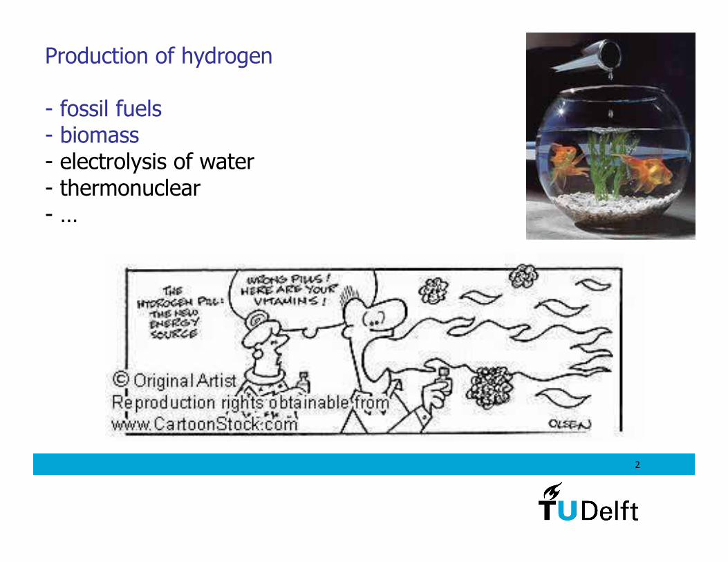
Production of hydrogen
- fossil fuels- biomass- electrolysis of water- thermonuclear- …
3
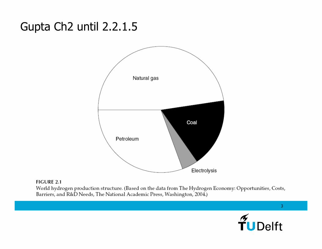
Gupta Ch2 until 2.2.1.5
4
Hydrocarbons are reformed:
CnHm + n H2O → n CO + (m/2 + n) H2 ’synthesis gas’
The case of methane:
CH4 + H2O → CO + 3H2 + ∆H1
with ∆H1= -206 kJ/mol (steam)
Current production of hydrogen: from fossil fuels mainly
1
This is a strongly endothermic reaction (costs energy) that requires catalysts (Ni or other). It requires more energy if thewater is added as liquid.Process conditions: 850 oC, 25 Bar
5
Subsequently the CO is used for:
CO + H2O → CO2 + H2 + ∆H2
with ∆H2= +41.1 kJ/mol (steam)
This reaction is called the ‘Water-Gas Shift reaction’ (WGS).
2
During 1 and 2 a surplus of H2O is used to prevent the formation of carbon, and to make sure that all CO reacts.
1+2 combine to
CH4+2H2O → CO2 + 4H2 + ∆H12
6
1+2+3: 2CH4 + 2O2 → 2CO2 + 4H2+ ∆Htot
Chemical conversion efficiency
This could reach 89% if one could use the energy in the steam.Then the conversion appears to be highly efficient.
Required input heat during these reactions comes from burningsome of the fuel:
3 CH4 + 2O2 → CO2 + 2H2O + ∆H3
∆H3= 802.4 (g) or 894.7 (l) kJ/mol (g/l: gas/liquid)
Lower heating value Upper heating value
7
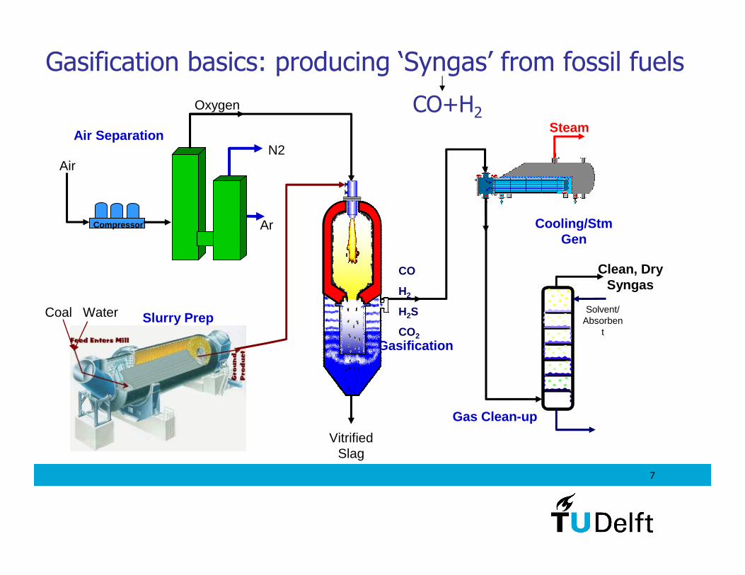
Gasification basics: producing ‘Syngas’ from fossil fuels
CO+H2
Coal Water Slurry Prep
Gasification
Vitrified Slag
CO
H2
H2S
CO2
Steam
Cooling/StmGen
Gas Clean-up
Clean, Dry Syngas
Solvent/ Absorben
t
Compressor Ar
N2
Oxygen
Air
Air Separation
8
Carbon formation
Unwanted side reactions:
CH4 + 74.9kJ/mol → C + 2H2
2CO → C + CO2 + 172.4 kJ/mol ‘Boudouard reaction’
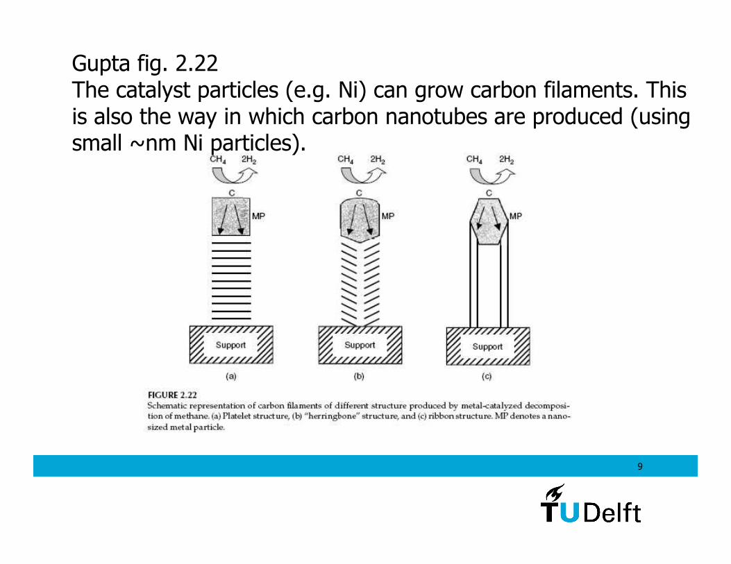
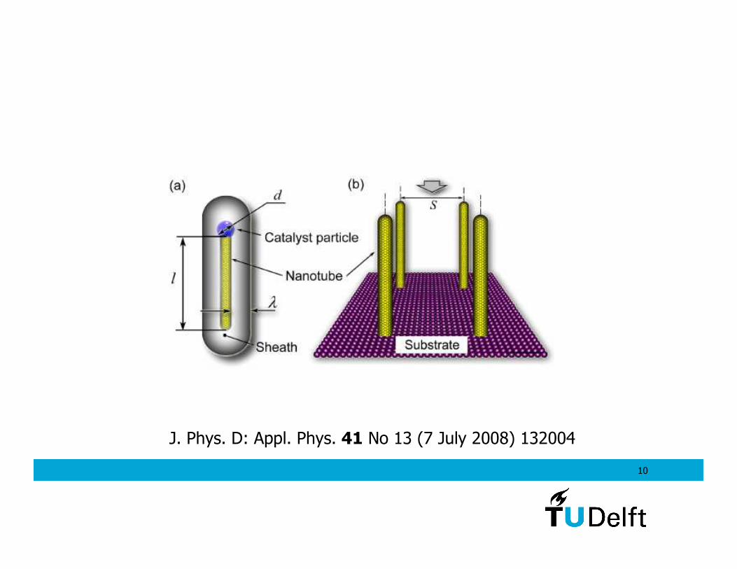
This C is mainly problematic for the catalysts in the process:they may become covered and blocked by spontaneously growing carbon filaments.
(application of this type of reaction is the production of carbon nanotubes)
9
Gupta fig. 2.22The catalyst particles (e.g. Ni) can grow carbon filaments. Thisis also the way in which carbon nanotubes are produced (using small ~nm Ni particles).
10
J. Phys. D: Appl. Phys. 41 No 13 (7 July 2008) 132004
11
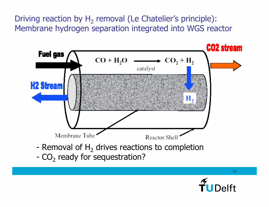
- Removal of H2 drives reactions to completion- CO2 ready for sequestration?
Driving reaction by H2 removal (Le Chatelier’s principle):Membrane hydrogen separation integrated into WGS reactor
12
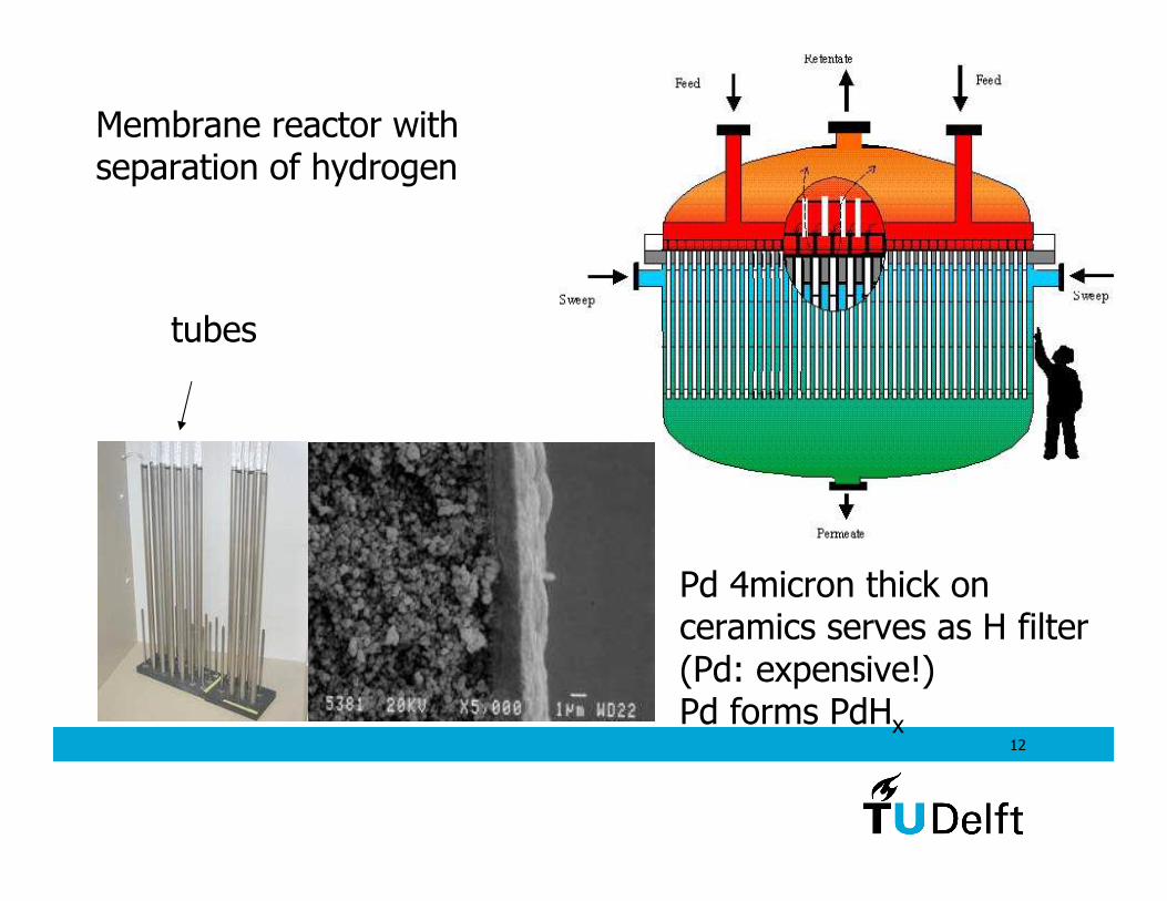
Membrane reactor withseparation of hydrogen
Pd 4micron thick on ceramics serves as H filter(Pd: expensive!) Pd forms PdHx
tubes
13
Conclusions hydrogen from fossil fuels- high efficiency conversion of fossil fuels to hydrogen is possibleusing gasification.- the presence of CO and other impurities that come from the fossil fuel pose problems for fuel cell catalysts.- We will see: high purity of H2 can be obtained by various separation methods.
Obvious drawbacksFossil fuels are depleting and are not renewable (at least on human timescales).CO2 emissions continue unless large scale sequestration is realized. Capturing the CO2 is relatively straightforward with the various gas separation techniques (but how to store itstill needs to be resolved).
14
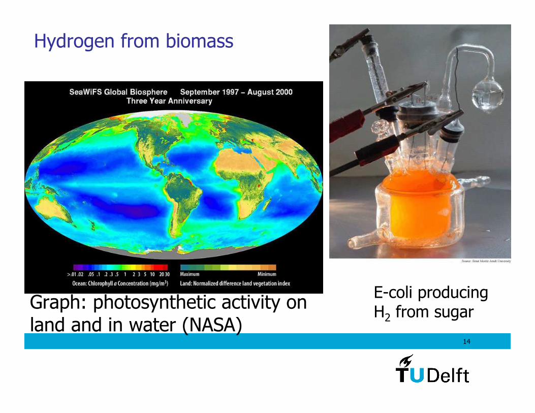
Hydrogen from biomass
E-coli producingH2 from sugar
Graph: photosynthetic activity on land and in water (NASA)
15
Production of hydrogen from biomass
Why?
- CO2 neutral: as much CO2 returned as captured- Make use of waste streams present from food production- Make use of waste land or algae in the sea
Why not?
- possibly better to make ethanol, methanol or methane - can reduce biodiversity (no ‘apes for oil/H2’)- competition with food production- depletion of soils - low energy yield after all the transportation, processing costs
16
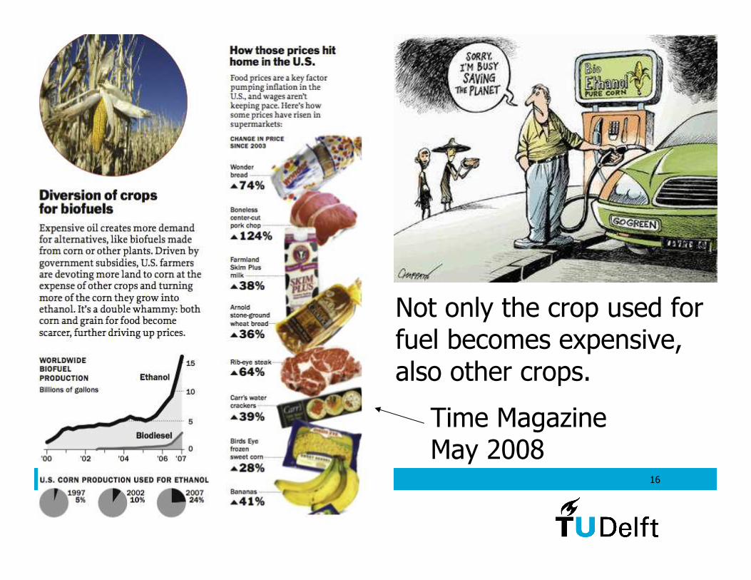
Time MagazineMay 2008
Not only the crop used forfuel becomes expensive, also other crops.
17
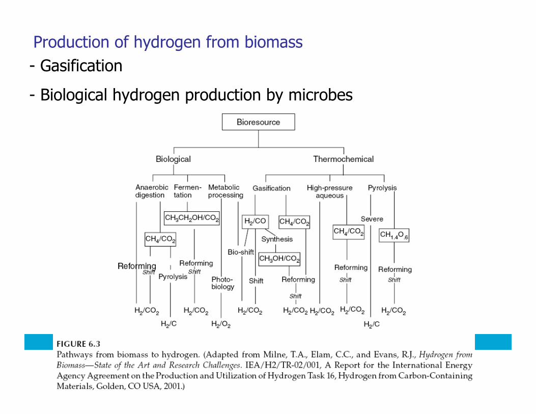
- Gasification
- Biological hydrogen production by microbes
Production of hydrogen from biomass
18
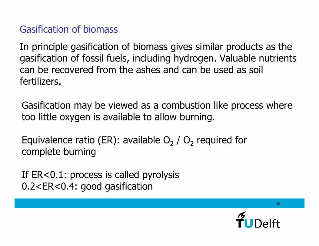
Gasification of biomass
In principle gasification of biomass gives similar products as the gasification of fossil fuels, including hydrogen. Valuable nutrients can be recovered from the ashes and can be used as soil fertilizers.
Gasification may be viewed as a combustion like process where too little oxygen is available to allow burning.
Equivalence ratio (ER): available O2 / O2 required for complete burning
If ER<0.1: process is called pyrolysis0.2<ER<0.4: good gasification
19
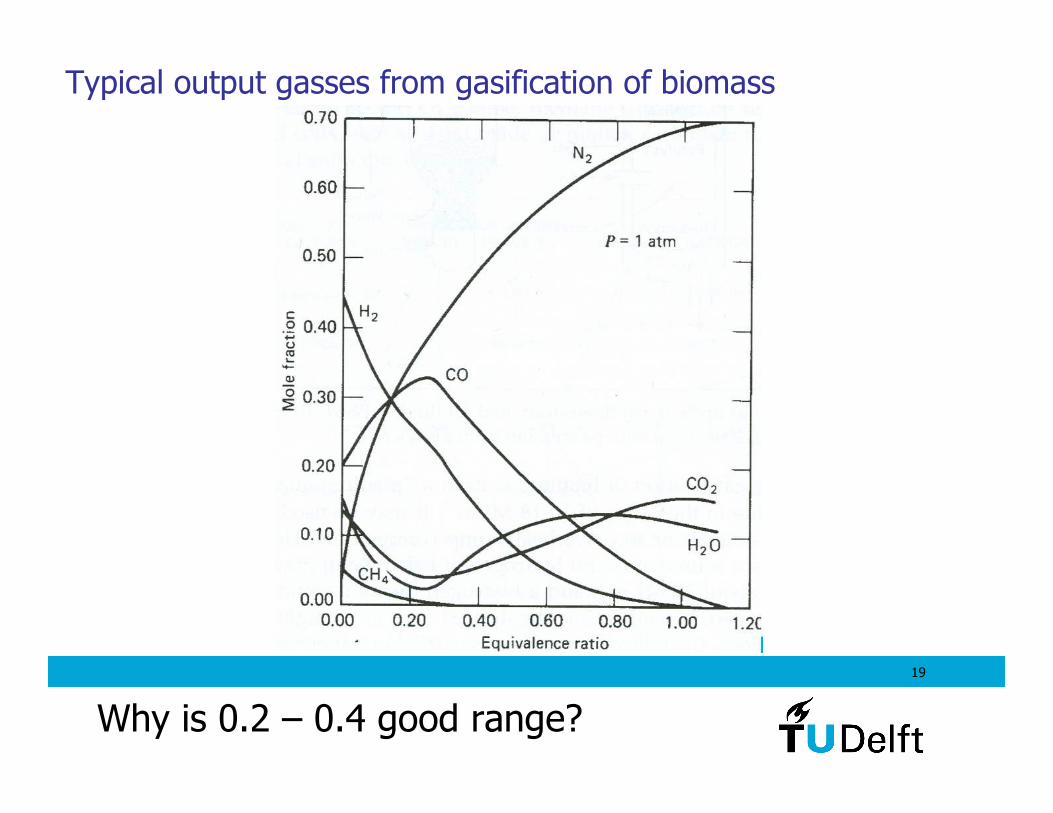
Typical output gasses from gasification of biomass
Why is 0.2 – 0.4 good range?
20
High H2 and CO, low H2O, CO2, CH4. CO can be used in WGS to produce more H2.
Why is 0.2 – 0.4 good range?
21
Pretreatment of biomass
To enable:reliable feeding systems, transport, storage and handling
Methods:drying, chipping, densification, sizing in certain shapes. Sometimes also leaching to remove salts before gasification.
Maximum water content that is allowable: 35%
22
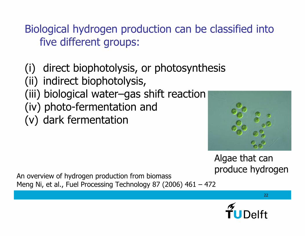
Biological hydrogen production can be classified into five different groups:
(i) direct biophotolysis, or photosynthesis(ii) indirect biophotolysis, (iii) biological water–gas shift reaction(iv) photo-fermentation and (v) dark fermentation
An overview of hydrogen production from biomassMeng Ni, et al., Fuel Processing Technology 87 (2006) 461 – 472
Algae that can produce hydrogen
23
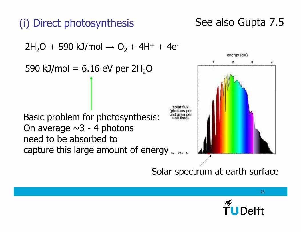
(i) Direct photosynthesis
2H2O + 590 kJ/mol → O2 + 4H+ + 4e-
590 kJ/mol = 6.16 eV per 2H2O
Solar spectrum at earth surface
Basic problem for photosynthesis:On average ~3 - 4 photonsneed to be absorbed tocapture this large amount of energy
See also Gupta 7.5
24
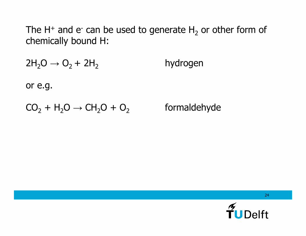
The H+ and e- can be used to generate H2 or other form of chemically bound H:
2H2O → O2 + 2H2 hydrogen
or e.g.
CO2 + H2O → CH2O + O2 formaldehyde
25
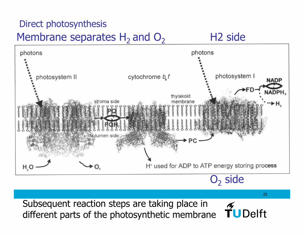
Membrane separates H2 and O2 H2 side
O2 side
Direct photosynthesis
Subsequent reaction steps are taking place in different parts of the photosynthetic membrane
26
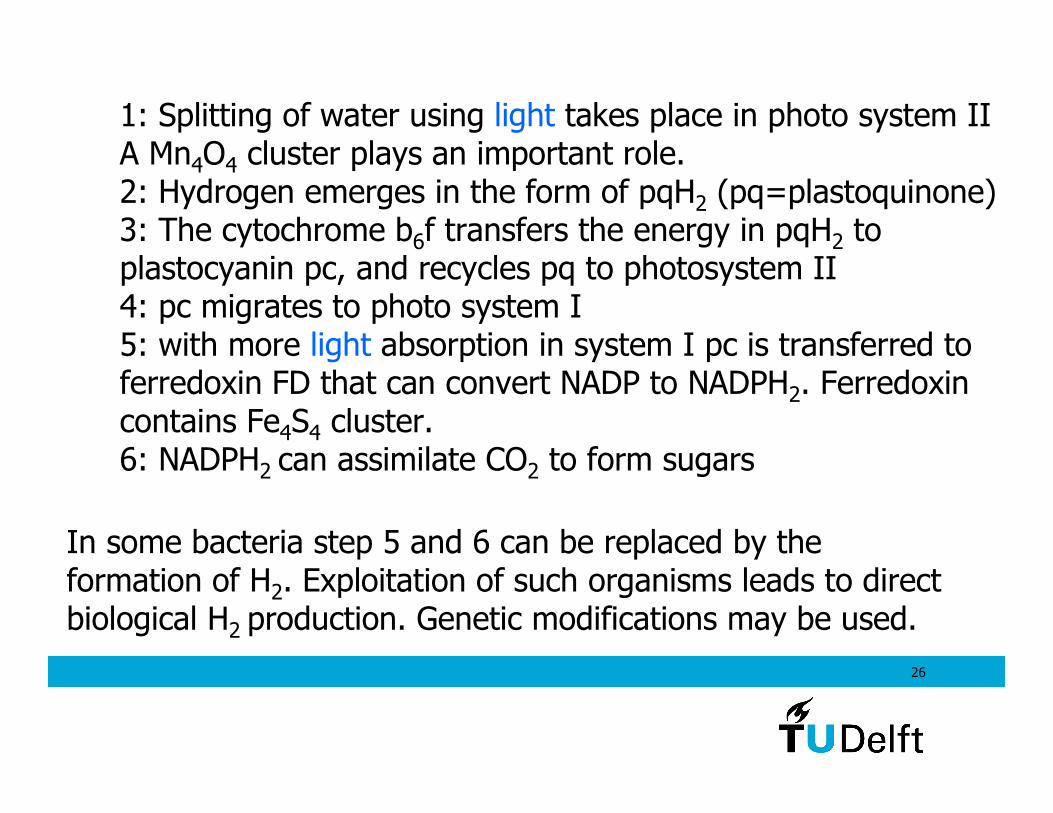
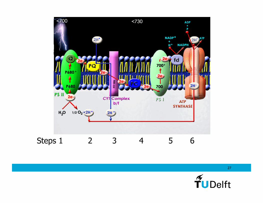
1: Splitting of water using light takes place in photo system IIA Mn4O4 cluster plays an important role.2: Hydrogen emerges in the form of pqH2 (pq=plastoquinone)3: The cytochrome b6f transfers the energy in pqH2 to plastocyanin pc, and recycles pq to photosystem II4: pc migrates to photo system I5: with more light absorption in system I pc is transferred to ferredoxin FD that can convert NADP to NADPH2. Ferredoxincontains Fe4S4 cluster. 6: NADPH2 can assimilate CO2 to form sugars
In some bacteria step 5 and 6 can be replaced by the formation of H2. Exploitation of such organisms leads to direct biological H2 production. Genetic modifications may be used.
27
Steps 1 2 3 4 5 6
28
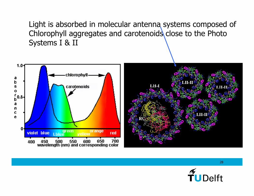
Light is absorbed in molecular antenna systems composed ofChlorophyll aggregates and carotenoids close to the Photo Systems I & II
29
Direct photosynthesis possibilities- biological processes aim to benefit the organism, and produce sugars or also H2 for internal use only, not for our use.
- genetic modification may alter the amount of H2 produced
- solar ray to biomass conversion has 0.2% efficiency as a globalaverage, rising to 2% in coral reefs (this low compared to PV )
- solar ray energy to H2 conversion may be 1% efficient in theory(Compare to normal solar cell (>10%)+ electrolyser (70%): 10*0.7%)
- biomass produced may be used for hydrogen/oil/ethanol
- algae and cyanobacteria are most promising organisms
30
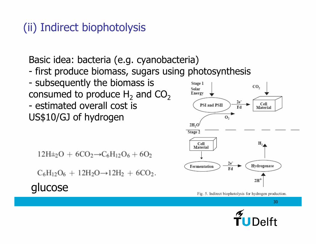
(ii) Indirect biophotolysis
Basic idea: bacteria (e.g. cyanobacteria)- first produce biomass, sugars using photosynthesis- subsequently the biomass is consumed to produce H2 and CO2
- estimated overall cost is US$10/GJ of hydrogen
glucose
31
Some bacteria can live from energy using light (photosynthesis) but still survive in the dark thanks to the ability to feed on C containing feed stocks like CO:
CO + H2O → CO2 + H2 ∆H=-20.1kJ/mol
These bacteria can thus produce energy and H2.
This is in the research stage: finding organisms,determining feasibility, cost, genetic modification, etc.
(iii) Biological water–gas shift reaction
32
Metabolically engineer Escherichia coli for hydrogen production. It is one of the easiest strains to manipulate genetically.
Example in Microbial Biotechnology (2008) 1(1), 30–39:
Modifying genes to switch on:- 141 x higher H2 production from formate (CHOO- ion)HCOO- + H2O ↔ H2 + HCO
-3
- 50% increase from glucose
Genetic engineering of bio reactions
Researchers remark that this actually weakens the bacteria because they loose part of their energy to hydrogen production.
33
(iv,v) Biological fermentation
Fermentation: production of energy-rich liquid/gas from organic substrate under oxygen-free and dark conditions.
Conversion of glucose to hydrogen (and acids, CO2):
C6H12O6 + 2H2O → 2CH3COOH + 2CO2 + 4H2 + 184.2 kJ/mol
C6H12O6 → CH3CH2CH2COOH + 2CO2 + 2H2 + 257.1 kJ/mol
34
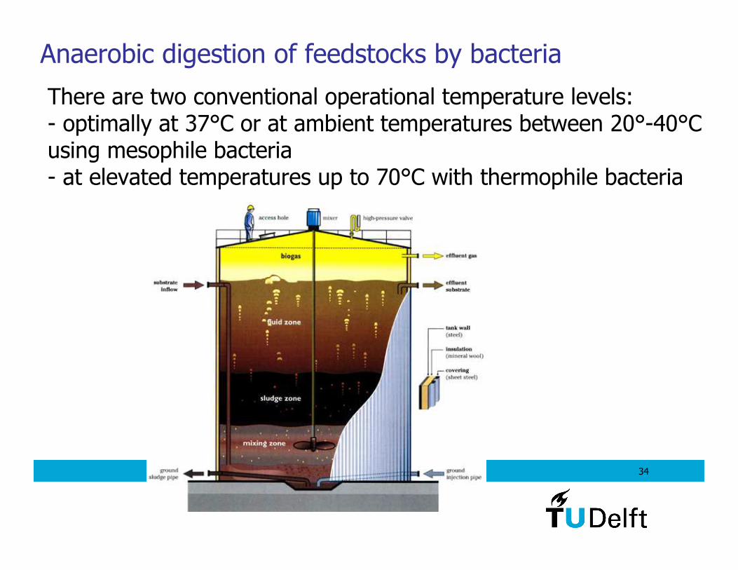
There are two conventional operational temperature levels:- optimally at 37°C or at ambient temperatures between 20°-40°C using mesophile bacteria- at elevated temperatures up to 70°C with thermophile bacteria
Anaerobic digestion of feedstocks by bacteria
35
- When bacteria grow on organic substrates, these substratesare degraded by oxidation to provide building blocks andmetabolic energy for growth.
- This oxidation generates electrons which need to be disposed of to maintain electrical neutrality.
- In aerobic or oxic environments, oxygen is reduced and water is the product.
- In anaerobic or anoxic environments, other compoundsneed to act as electron acceptor and protons that are reduced to molecular hydrogen can fulfill this role.
36
Main fuel product
CH4 and H2
Important by-products:
Lignin and chitin. Currently this part is rather indigestible and needs further processing in order to yield useful biofuels. Simplestsolution: produce hydrogen by gasification.
- liquid leftovers containing minerals, trace elements, …Depending on content this should be ingredients forfertilizers required for new crop growth.
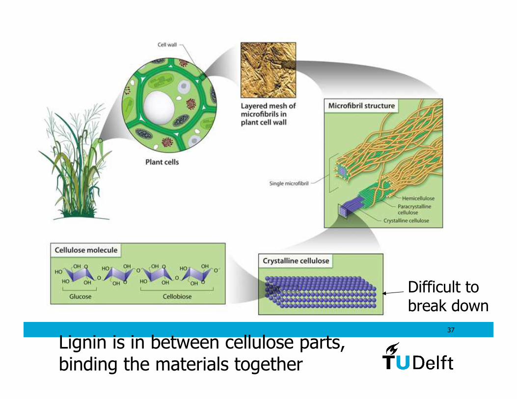
37
Difficult to break down
Lignin is in between cellulose parts,binding the materials together
38
Dealing with living organisms means that the conditions of sugar supply, heat, water and the removal of products needs to be optimal. Otherwise the fermentation may be varying in yield or may stop altogether.
Yield of fermentation processes is lower than other processes like the gasification. This makes that improvements are required.
Fermentation uses living organisms
39
Biotechnology goal: finding enzymes that can break up
lignin, chitin and cellulose to produce alcohols, hydrogen
40
Energy yield Gupta 6.1.4Typical dry mass of biomaterials are: C: 30 – 60 %H: 5-7%O: 30-45%Due to low C and high O content typical LHV are 10 – 18MJ/kg.Compare to coal: 30 MJ/kg
Critical assessment is necessary to evaluate energy yield:- growing, harvesting and transport to hydrogen production sites. Significant logistic operations.- new crops need to be planted and fertilizer added. The energy invested for all processing, transport, … needs to be taken into account when determining the overall yield. There stillis energy gained.
41
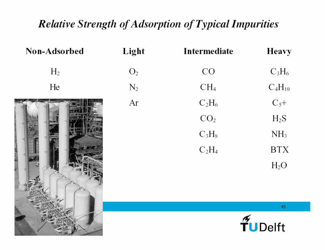
Hydrogen collection from gas streams;separation and purification Gupta Ch8.3
Various methods exist for the separation of hydrogen from other gases including CO2, H2O, …
- Pressure sweep adsorption method mature- Membrane separation research- Cryogenic separation mature
42
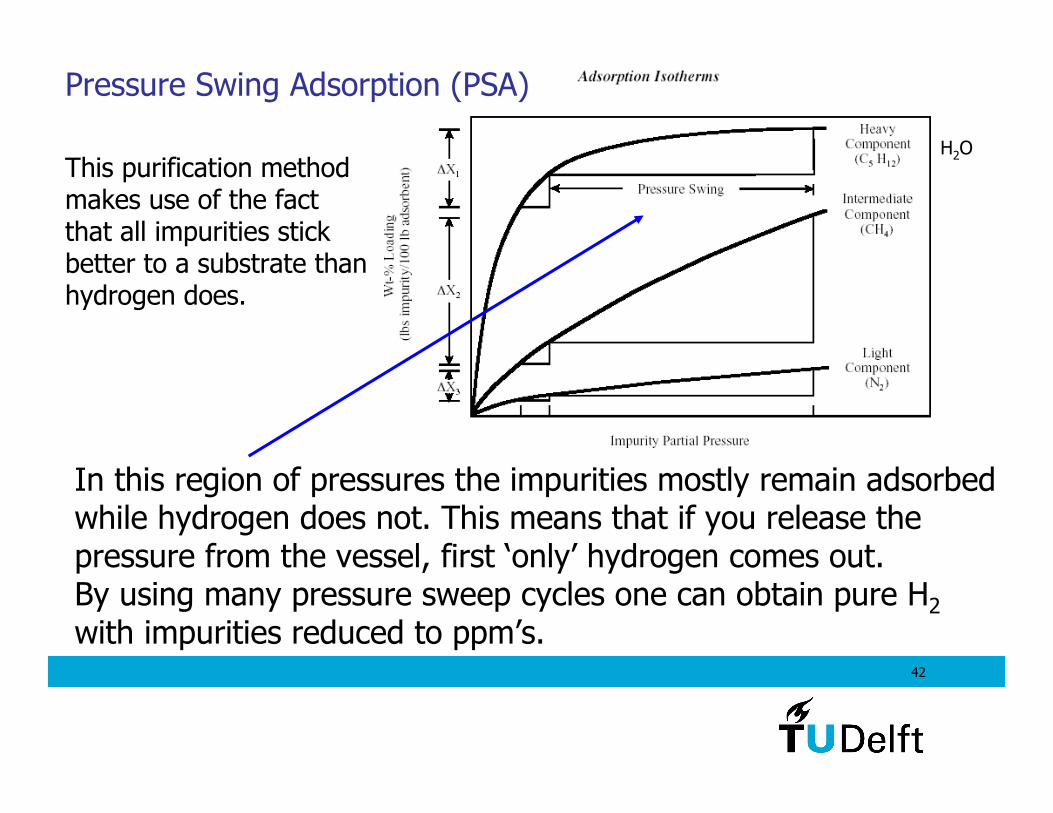
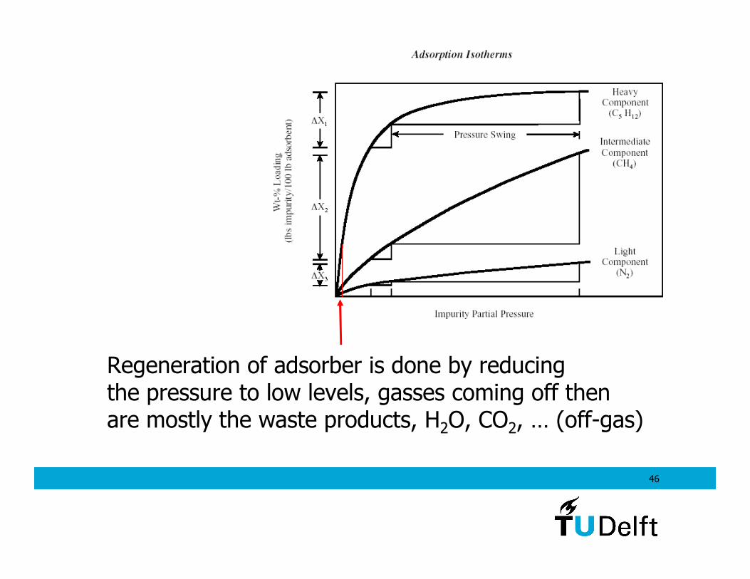
In this region of pressures the impurities mostly remain adsorbed while hydrogen does not. This means that if you release the pressure from the vessel, first ‘only’ hydrogen comes out.By using many pressure sweep cycles one can obtain pure H2
with impurities reduced to ppm’s.
Pressure Swing Adsorption (PSA)
H2OThis purification methodmakes use of the fact that all impurities stickbetter to a substrate thanhydrogen does.
43
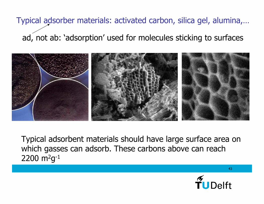
Typical adsorber materials: activated carbon, silica gel, alumina,…
Typical adsorbent materials should have large surface area onwhich gasses can adsorb. These carbons above can reach 2200 m2g-1
ad, not ab: ‘adsorption’ used for molecules sticking to surfaces
44
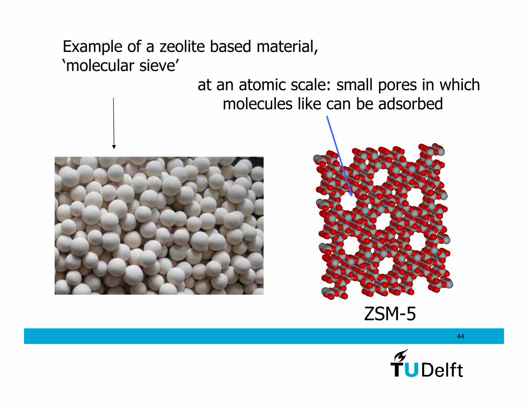
Example of a zeolite based material,‘molecular sieve’
at an atomic scale: small pores in which molecules like can be adsorbed
ZSM-5
45
46
Regeneration of adsorber is done by reducingthe pressure to low levels, gasses coming off then are mostly the waste products, H2O, CO2, … (off-gas)
47
Membrane materials for purification:
- high temperature ceramics with hydrogen permeable noblemetal top layers for inside reactors
- polymer membranes can be used at lower temperatures. The difference in diffusion coefficient for hydrogen compared to othergasses is used as separation mechanism.
These membrane reactors are relatively new developments. Research is required for durability, performance, yield, cost issues.
48
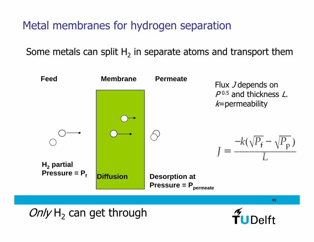
MembraneFeed Permeate
H2 partialPressure = P f Diffusion Desorption at
Pressure = P permeate
Metal membranes for hydrogen separation
Some metals can split H2 in separate atoms and transport them
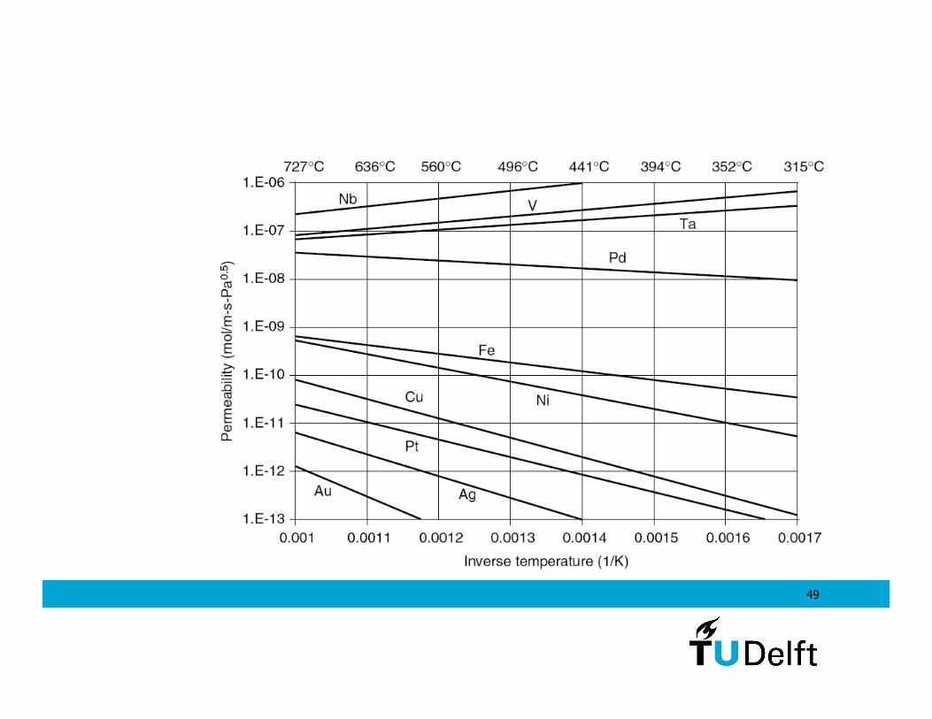
Flux J depends onP 0.5 and thickness L.k=permeability
Only H2 can get through
49
50
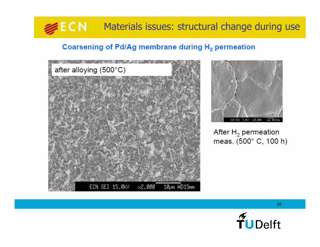
Materials issues: structural change during use
51
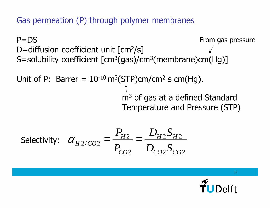
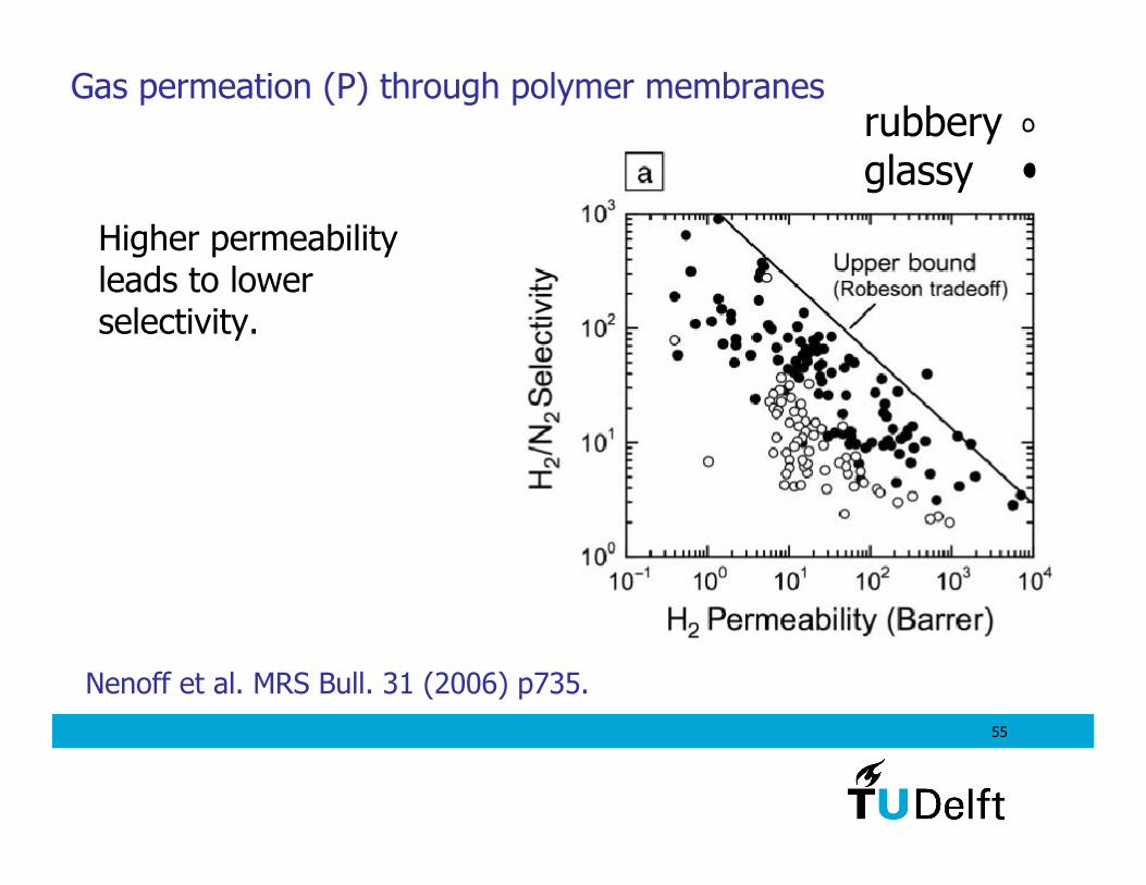
Gas permeation (P) through polymer membranes
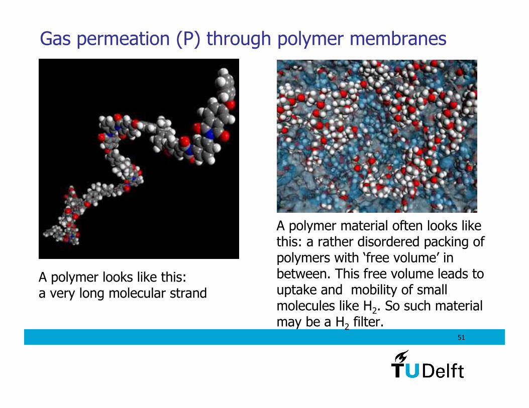
A polymer looks like this: a very long molecular strand
A polymer material often looks like this: a rather disordered packing of polymers with ‘free volume’ in between. This free volume leads to uptake and mobility of small molecules like H2. So such materialmay be a H2 filter.
52
Gas permeation (P) through polymer membranes
P=DSD=diffusion coefficient unit [cm2/s]S=solubility coefficient [cm3(gas)/cm3(membrane)cm(Hg)]
Unit of P: Barrer = 10-10 m3(STP)cm/cm2 s cm(Hg).
From gas pressure
m3 of gas at a defined StandardTemperature and Pressure (STP)
2 2 22/ 2
2 2 2
H H HH CO
CO CO CO
P D S
P D Sα = =Selectivity:
53
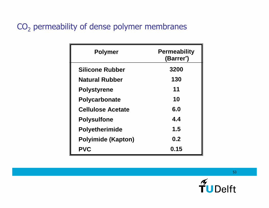
CO2 permeability of dense polymer membranes
Silicone Rubber
Natural Rubber
Polystyrene
Polycarbonate
Cellulose Acetate
Polysulfone
Polyetherimide
Polyimide (Kapton)
PVC
3200
130
11
10
6.0
4.4
1.5
0.2
0.15
Polymer Permeability(Barrer *)
54
Membrane selectivity
Silicone Rubber
Natural Rubber
Polystyrene
Polycarbonate
Cellulose Acetate
Polysulfone
Polyetherimide
Polyimide (Kapton)
PVC
3200
130
11
10
6.0
4.4
1.5
0.2
0.15
Polymer Permeability(Barrer)
SelectivityCO2/CH4
3.4
4.6
8.5
26.7
31
28
45
64
15.1
α i,j = Pi
Pj = si Di
sj Dj
P = D * S
55
Nenoff et al. MRS Bull. 31 (2006) p735.
Gas permeation (P) through polymer membranes
Higher permeabilityleads to lowerselectivity.
rubberyglassy
56
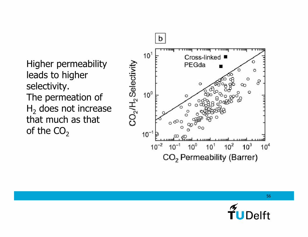
Higher permeabilityleads to higherselectivity.The permeation ofH2 does not increase that much as thatof the CO2
57
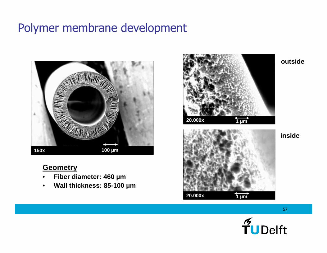
Polymer membrane development
outside
inside
20.000x 1 µm
150x 100 µm
Geometry• Fiber diameter: 460 µm• Wall thickness: 85-100 µm
20.000x 1 µm
58
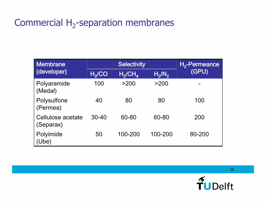
Commercial H2-separation membranes
80-200100-200100-20050Polyimide (Ube)
20060-8060-8030-40Cellulose acetate (Separax)
100808040Polysulfone(Permea)
->200>200100Polyaramide(Medal)
HHHH2222/N/N/N/N2222HHHH2222/CH/CH/CH/CH4444HHHH2222/CO/CO/CO/COHHHH2222----PermeancePermeancePermeancePermeance
(GPU)(GPU)(GPU)(GPU)SelectivitySelectivitySelectivitySelectivityMembrane Membrane Membrane Membrane
(developer)(developer)(developer)(developer)
59
What do you expect is the difference in selectivityfor H2 between a polymeric filter and a Nb filter?
The Nb has infinite selectivity since it has no CO2 uptake
60
Cryogenic separation of gasses
- Uses the difference in boiling temperatures (relative volatilities) of the gas components to effect the separation. Hydrogen has the lowest of all gasses involved.
- Condensation of water is obtained by cooling the gas stream against the fuel gas streams in heat exchangers.
- Refrigeration is obtained by expansion of the compressed hydrogen + exhaust products.
- At low temperature CO2 and impurities condense while H2 does not condense until very low T.
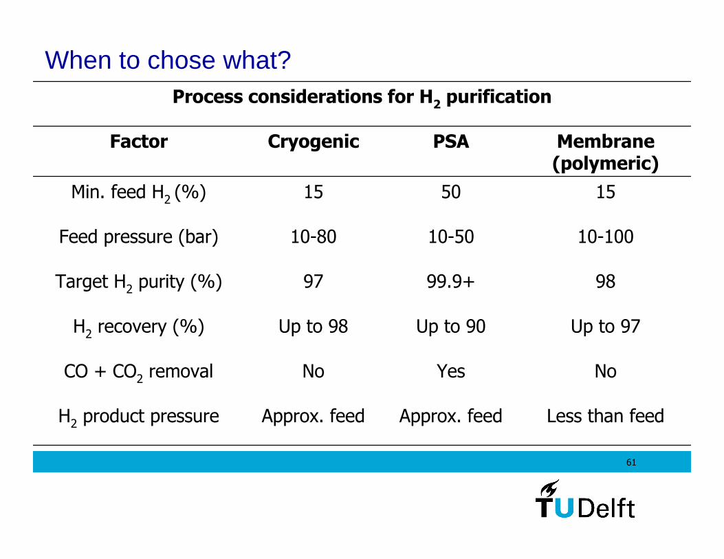
61
When to chose what?
Less than feedApprox. feedApprox. feedH2 product pressure
NoYesNoCO + CO2 removal
Up to 97Up to 90Up to 98H2 recovery (%)
9899.9+97Target H2 purity (%)
10-10010-5010-80Feed pressure (bar)
155015Min. feed H2 (%)
Membrane(polymeric)
PSACryogenicFactor
Process considerations for H2 purification
62
IntermezzoWhat level of CO, CO2 impurities can be accepted in hydrogen as a fuel for fuel cells?
CO adsorbs on the Pt catalysts of fuel cells (FC), causing a dramatic reduction of the FC output power. At most ppm levels of CO are allowed.
A trace presence of carbon dioxide can also be detrimental, as this produces carbon monoxide through the reverse water-gas shift reaction: CO2+H2 → CO+H2O. And the catalyst for that is the Pt that is already present in the FC electrodes.
63
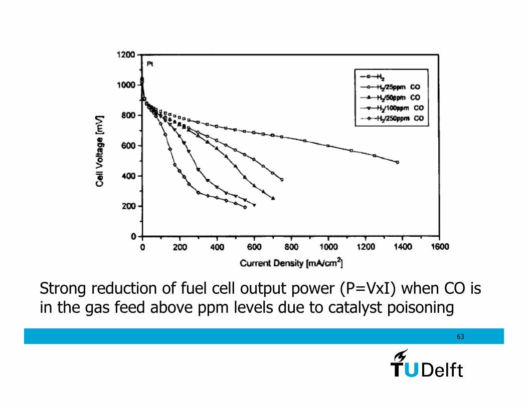
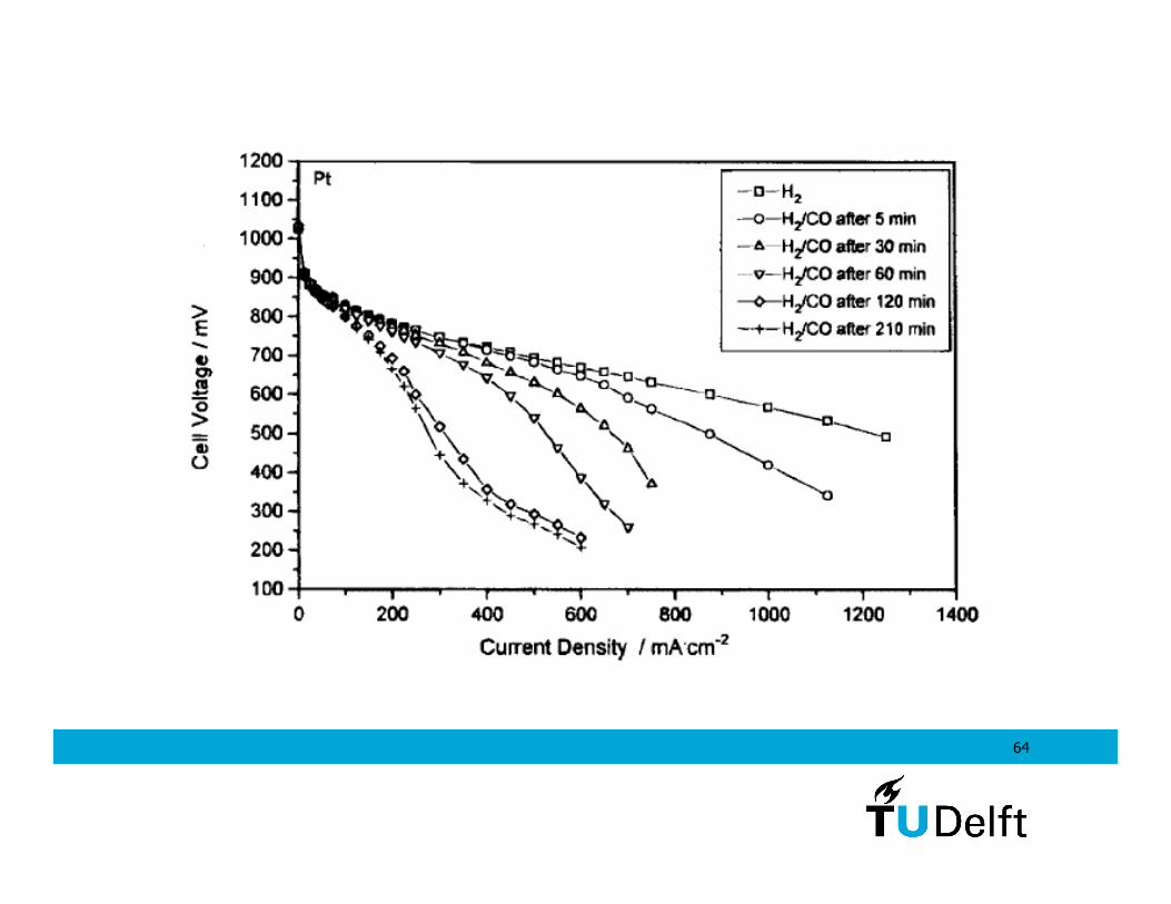
Strong reduction of fuel cell output power (P=VxI) when CO is in the gas feed above ppm levels due to catalyst poisoning
64
65
Sustainable Hydrogen and Electrical Energy Storage