Embed Size (px)
DESCRIPTION
Overview
Citation preview

1. Overview
1.1. Introduction
Modern thermal storage is a proven technology with numerous benefits formultiple stakeholders. In fact, thermal storage has been saving money forknowledgeable facility managers and building owners for several decades.Utility companies have also benefited from the implementation of thermalstorage over the years. The savings to utility companies, by eliminating theneed for additional power generation and transmission construction simplyto meet on-peak electric load, is so valuable to utilities that many utilitieshave provided financial incentives to facility owners to reduce the first cost ofthermal storage installation. In addition, utilities often offer electric ratesthat provide incentive to transfer consumption of power from on-peak to off-peak periods, when utility-wide electric demand is much lower.
This book provides proven techniques for reducing energy use and cost andeven potentially reducing capital costs with the use of thermal energystorage. It also provides a practical guide to the planning, design, basicconstruction, and operation of sustainable thermal storage systems.
There are several different types of energy storage methods includingmechanical energy storage, chemical energy storage, magnetic field energystorage (an up-and-coming field), and thermal energy storage. Each energystorage method has numerous storage technologies such as, for example,mechanical energy storage—pumped hydro, compressed air, and flywheels;chemical energy storage—fuel oil storage; and many different types ofbattery storage technologies. However, this book discusses thermal storage,which relates to storing sensible or latent thermal energy; it focuses
Overview
primarily on common applications of thermal storage in use today forbuilding or facility heating and cooling.
The addition or removal of sensible energy causes a change in a material orsubstance's temperature, whereas the addition or removal of latent energycauses a material or substance to change phase (e.g., turn from water to ice).These processes are discussed in detail in later chapters.
Thermal storage is a low-cost form of energy storage that is often highlyefficient. In fact, some thermal storage systems provide heating or coolingwith less input energy than a nonstorage conventional production at time ofuse system. When combined with less expensive energy input, thermalstorage provides a powerful "green" tool for the building or facility owner.
There are both passive and active thermal storage systems. Active thermalstorage systems use mechanical production and transportation heating orcooling equipment and prime movers such as fans or pumps with ducts orpiping; passive thermal storage systems do not. An example of passivethermal storage is the sun shining on a high mass wall. However, this bookfocuses primarily on active thermal storage systems.
At its most basic, thermal storage provides methods to separate the timewhen heating or cooling is produced or generated from the time when that
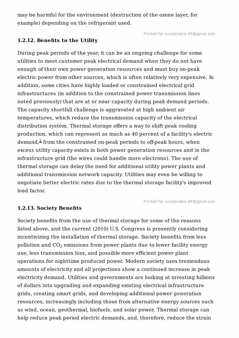
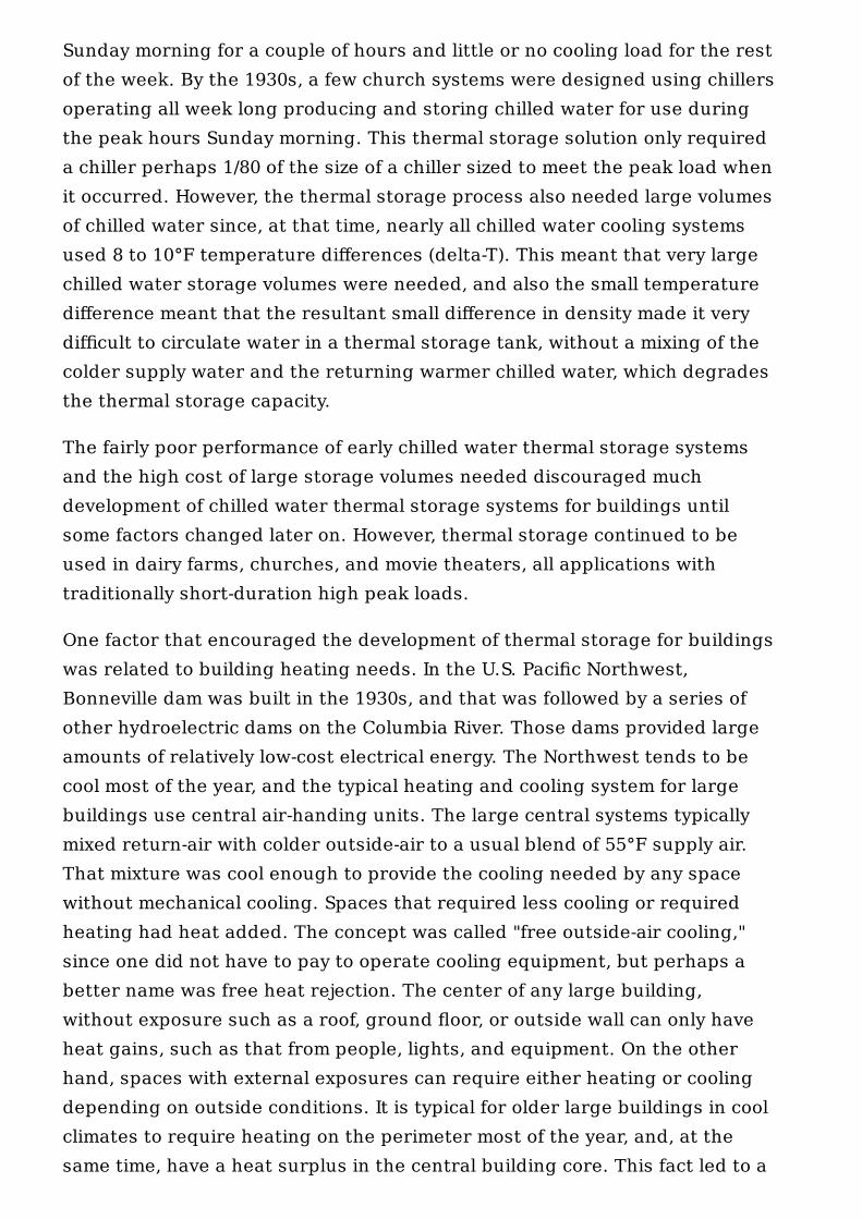
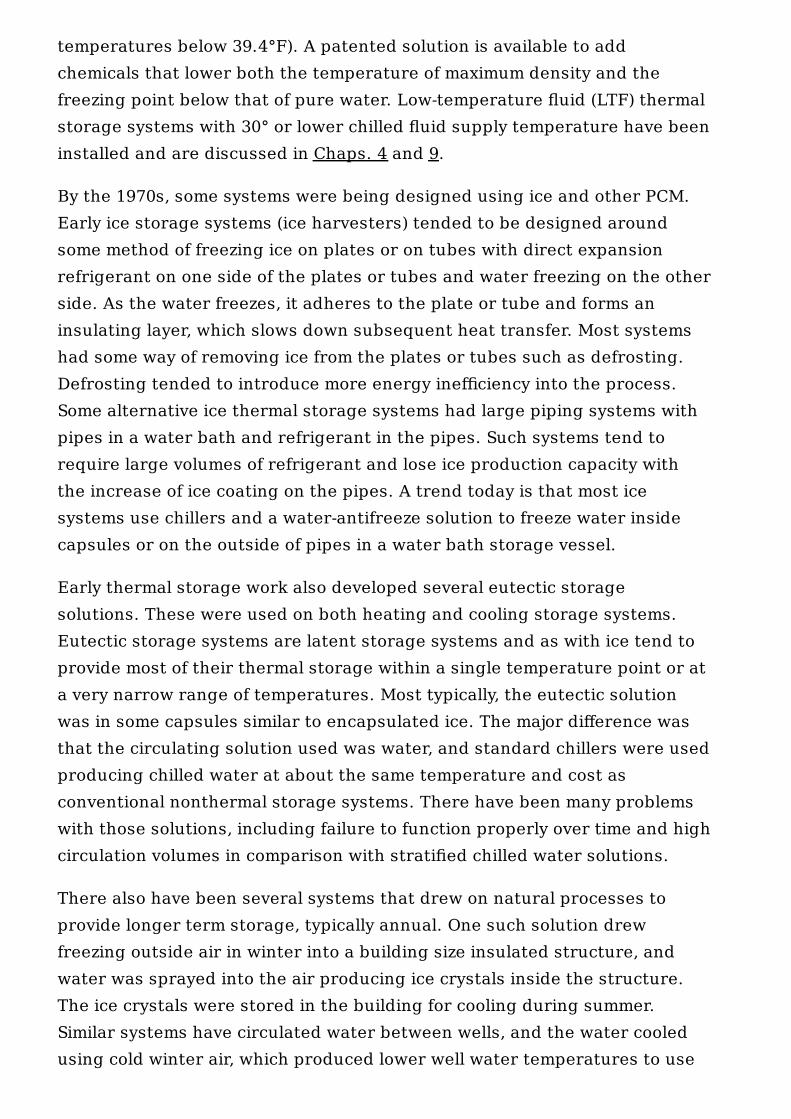
Figure 1-1. Aboveground stratified chilled water thermal storagetank under construction.
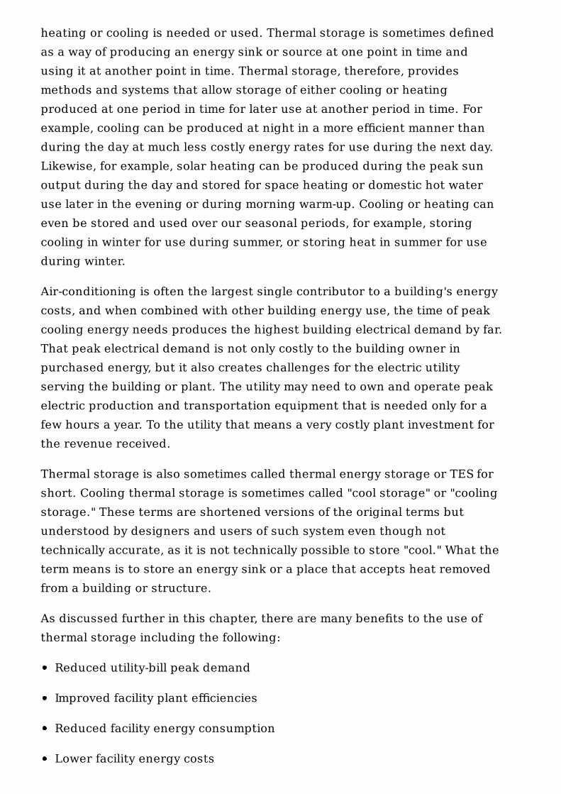
heating or cooling is needed or used. Thermal storage is sometimes definedas a way of producing an energy sink or source at one point in time andusing it at another point in time. Thermal storage, therefore, providesmethods and systems that allow storage of either cooling or heatingproduced at one period in time for later use at another period in time. Forexample, cooling can be produced at night in a more efficient manner thanduring the day at much less costly energy rates for use during the next day.Likewise, for example, solar heating can be produced during the peak sunoutput during the day and stored for space heating or domestic hot wateruse later in the evening or during morning warm-up. Cooling or heating caneven be stored and used over our seasonal periods, for example, storingcooling in winter for use during summer, or storing heat in summer for useduring winter.
Air-conditioning is often the largest single contributor to a building's energycosts, and when combined with other building energy use, the time of peakcooling energy needs produces the highest building electrical demand by far.That peak electrical demand is not only costly to the building owner inpurchased energy, but it also creates challenges for the electric utilityserving the building or plant. The utility may need to own and operate peakelectric production and transportation equipment that is needed only for afew hours a year. To the utility that means a very costly plant investment forthe revenue received.
Thermal storage is also sometimes called thermal energy storage or TES forshort. Cooling thermal storage is sometimes called "cool storage" or "coolingstorage." These terms are shortened versions of the original terms butunderstood by designers and users of such system even though nottechnically accurate, as it is not technically possible to store "cool." What theterm means is to store an energy sink or a place that accepts heat removedfrom a building or structure.
As discussed further in this chapter, there are many benefits to the use ofthermal storage including the following:
Reduced utility-bill peak demand
Improved facility plant efficiencies
Reduced facility energy consumption
Lower facility energy costs
More flexible plant operations and added backup capacity
Smaller equipment requirements
Lower maintenance costs
Potential lower capital costs
Greater economic benefits than the business-as-usual case
Adding thermal storage can make the existing production equipment serve afar greater load than the installed equipment capacity. When thermal storageis combined with measures to increase the temperature rise or drop (i.e.,delta-T) in existing air or water systems, the thermal storage solution oftenmeans greater loads can be served with the same pipes and pumps or fansand ducts.
Society also benefits with the installation of thermal storage due to lesspollution as a result of more efficient facility and utility operations as well asless polluting utility operations at night (depending upon the fuel–power mixused by the utility to produce electric power during thermal storagecharging).
As discussed in Chap. 2, thermal storage technology can be and has beenused by a variety of facilities and buildings including residential, commercial,and institutional for both the public and private sectors.
One typical highly desirable condition to use thermal storage is to have abuilding(s) or facility where the loads are cyclical or otherwise variable overtime. The time period is often daily but can be weekly, seasonal, or even shortterm, for example, 10 to 20 minutes for emergency cooling. If the facility orbuilding has a very flat load profile, thermal storage may not be suitable forload shifting, unless there is a significant difference in energy costs at onepart of the day over other periods of the day. Another case for thermalstorage with a constant load is to serve as an emergency backup in case ofloss of heating or cooling production equipment. However, most facilities orbuildings have a cyclical load profile.
Thermal storage systems are often most economical in locations that havetime-dependent energy costs. For example, many utility companies chargemore for on-peak power consumption (power used during the day) than foroff-peak power consumption (power used during the night). In addition to

energy consumption charges, most utilities also charge for peak power use.Thermal storage offers a powerful tool to reduce peak power demand. Someutilities provide economic incentives such as super off-peak pricing toencourage off-peak cooling production as well as utility rebates for theinstallation of thermal storage. One recent design will receive more than $4million from the local utility company to assist with their thermal storageinstallation. Another client buys power from the utility, as well as generatingmuch of their own electric power on site, and dispatches thermal storage tostore produced chilled water using very low-price power. The serving utilityhas a large nuclear plant base and during some nights actually pays theproject to use electricity. At other times, the combined real-time-pricingdemand costs for electricity may approach $1000 per megawatt (MW). Duringthose expensive utility time periods, the stored chilled water is used to meetcampus cooling needs. The use of thermal storage with smart meters andreal-time-pricing offers the opportunity for enhanced energy cost savingsthrough specifically targeted peak demand reduction in those hours with thehighest overall energy cost rates.
Thermal storage is often the most economically attractive:
1. When new facilities or buildings are constructed
2. When new facility expansions are planned
3. When old plant equipment needs to be replaced with new equipment
Life-cycle cost analysis often shows that employing thermal storage is thelowest life-cycle cost option among the many alternatives analyzed.
Thermal storage can also provide important benefits to utility electricgenerating and combined heat and power (CHP) plants when used forcombustion turbine inlet-air cooling (CTIC).
There are a number of materials that can be used as a storage medium inthermal storage systems. The most common material is water, either as aliquid or as a solid. The most typical water thermal storage systems includestratified chilled water thermal storage systems, different types of icestorage systems for cooling, and hot water storage systems for heating. Asdiscussed in this book, each type of thermal storage material and thermalstorage system has its own thermal storage, equipment, and systemrequirements. Each system also has its own advantages and disadvantages.

The past two to three decades have refined the thermal storage systemscommonly used so that over time many of the thermal storage systems thatwere once tried and proved less successful are no longer used.
Thermal storage is becoming ever more important as energy costs rise andcapital resources are ever scarcer. In addition, thermal storage is animportant piece of the "green" solution puzzle to successfully incorporaterenewable energy resources such as solar power and wind power into thepower grid.
1.2. Benefits of Thermal Storage
As outlined above, there are many benefits to the use of thermal storage.The following paragraphs provide an overview of some of the many benefitsof thermal storage.
1.2.1. Reduced Utility-Bill Peak Demand
As will be shown and explained in this book, the use of thermal storage canallow a facility or building to reduce or virtually eliminate the on-peakelectrical demand associated with facility cooling production. Demand is anengineering name for the instantaneous rate of consumption of the itembeing measured. Examples include flow, cooling load, heating load, or mostcommon electric power. Utility companies, in particular, measure a facility'selectric power use both by the amount of total electrical energy consumption(often measured in kilowatthours, kWh) over a particular time period (e.g.,monthly) and also by the peak power consumption rate, that is, the maximumdemand (often measured in kilowatts, kW) during certain utility rate timeperiods; the utility company measures, records, and charges for themaximum peak power demand during each utility rate time period. Inderegulated or re-regulated utility environments, there may be real-timepricing (RTP) or spot market rates, which will also reflect time-of-usevariations in electricity costs.
Fortunately, the facility on-peak (and even mid-peak) power demand, typically,the most expensive utility rate period, can be reduced through the use ofthermal storage. For example, as shown in Chap. 7, and known as fullstorage, cooling production can occur at night (with subsequent recordedenergy consumption and demand costs accruing to the facility during thatnighttime period), with only the thermal storage system operating the next

day, during the peak cooling load period, to supply all of the facility's coolingneeds with all of the cooling production equipment turned off (except forchilled water distribution pumps and facility air-handling units, which supplyconditioned air to building occupants, and are, of course, turned onwhenever a facility is occupied, whatever the cooling or heating methodemployed). As cooling production equipment is turned off during the on-peakperiod in this example, no electric power is, of course, required to operatethe cooling production equipment, and the facility electric power demand is,therefore, reduced accordingly. Note that the facility cooling or heating loador demand itself is not reduced, just the cooling production equipmentdemand required to meet the facility load during the on-peak period, asoperations required to meet the facility cooling load are modified, and, as willbe seen, smaller production equipment can be used to meet the facilitiescooling load.
1.2.2. Improved Facility Plant Efficiencies
As noted above, with cool thermal storage, cooling production equipment(e.g., chillers) are often operated more at night, when air temperatures (dry-bulb and wet-bulb) are typically lower than during the day. The amount ofwork and hence energy required by cooling production equipment per unit ofcooling produced is, in part, a function of the condensing temperature, whichis a function of the outside air temperature. In fact, for installed coolingsystems, at any given time, the condensing temperature is often a majorfactor in cooling system efficiency performance, since many of the otherefficiency factors are fixed for an installed cooling system. Lowering thecondensing temperature can improve cooling production equipment energyefficiencies by up to approximately 1.5 percent for each degree Fahrenheitthat the condensing temperature is lowered below the design condensingtemperature.
Another contributor to improved chiller efficiency, with thermal storagesystems, is that chiller equipment runs at full load most of the time, resultingin better overall plant kW-per-ton performance than when chiller equipmentruns at low part load. Further, many ancillary components such as condenserpumps, cooling towers and similar appurtenances are based on full chillerload and do not unload linearly (if at all) with cooling load reductions.Therefore, operating mechanical equipment at or close to full load isgenerally more efficient than part load operations, and plant fixed parasiticlosses are proportionally minimized at full load. Additionally, a fair amount of

losses are proportionally minimized at full load. Additionally, a fair amount ofmechanical equipment often operates more inefficiently at low part load thanat full load. As a result, conventional nonstorage chiller plants often havevery poor annualized performance due to excessive part load operations.However, there are some all-variable-speed systems that do try to minimizepower consumption at part load by adjusting individual equipment operatingspeeds.
1.2.3. Reduced Energy Consumption
As suggested, operating cooling production equipment more fully loaded atnight, when dry-bulb and wet-bulb air temperatures are lower, often resultsin higher facility cooling plant energy efficiency. This is due, in part, to lowercondensing temperatures at night but is also due to greater efficiency ofchiller operating at design point. Another factor is that when pumps andcooling towers are operating with a full design temperature difference, theenergy consumption per ton of cooling produced is less. Many nonstorageconventional plants, which must operate most of the year at part load, canuse more energy in pumping energy than in cooling production equipmentsuch as chillers or ice-makers. Another factor is that a well-designed thermalstorage often uses much higher delta-T and, therefore, less chilled water flowthan conventional systems, which must match delta-T to the chiller. Mostthermal storage systems use variable flow, and this also reduces pumpenergy use during part-load operations. Therefore, a well-planned, designed,and constructed thermal storage plant has lower overall cooling plant energyconsumption than conventionally operated nonstorage cooling plants.
1.2.4. Lower Energy Costs
Lower facility electric demand results in lower utility demand costs, whichare often a significant portion of the lower energy costs experienced byfacilities with installed thermal storage systems. However, reduced energyconsumption as well as shifting production from more expensive utilityenergy rate periods to less expensive utility energy rate periods also providefor lower facility energy costs. Based on experience, annual energy costsavings can be as much as 20 percent (and sometimes even more) dependingupon the thermal storage system installed. Installations with real-time-pricedpower have shown even greater savings.
1.2.5. More Flexible Facility Plant Operations

Thermal storage provides for more flexible plant operations. The thermalstorage system can act as a "buffer," and the rate of discharge from a thermalstorage system is typically variable from near zero discharge up to amaximum discharge flow rate as designed. Thermal storage systems areoften designed for facility peak load conditions, and, therefore, during non-peak load conditions (which are most of the hours of the year), plantoperations can easily be adjusted so that, for example, more coolingproduction occurs during off-peak hours with less cooling productionoccurring during mid-peak hours and no cooling production occurring duringon-peak hours (even if the thermal storage was designed as a partial storagesystem on the peak day). Further, during lower load periods of the year, itmay likely be possible, for example, for a cooling production unit (e.g., achiller) to be out of commission and for the cooling plant using thermalstorage still to be able to meet the facility's cooling load. In addition, duringthe case of an unforeseen plant shutdown, it may still be possible to servecritical loads for a period of time from thermal storage (if the thermal storagewas charged or partially charged when the unforeseen plant shutdownoccurred).
1.2.6. Added Backup Capacity
A daily thermal storage system is typically sized for the peak design day loadof the facility or building. On non-peak load days (which are the majority ofthe days throughout the year), the facility or building load can be met withless equipment capacity. Since less than full cooling generation equipmentcapacity is required during periods with lower loads, the additionalgeneration equipment available is in a sense added backup capacity. In somecases, one or two chillers or similar equipment units can be nonoperational(e.g., down for maintenance), and the facility plant can still meet the facilityload. In a real-life example, a chilled water storage system allowed foremergency cooling when the entire chilled water plant was down, bydumping ice into the storage tank.
1.2.7. Smaller Facility Equipment Requirements
As shown in Chap. 7, using thermal storage, it is possible to meet a facility'speak heating or cooling load with installed equipment smaller than thefacility's peak load. For example, a thermal storage system can be sized sothat on a peak day, the cooling production equipment operates at full load for
the entire 24 hours (known as partial storage), and, therefore, the coolingproduction equipment size required with partial thermal storage to meet thefacilities load is equal to the average load on the peak day (plus any desiredspare capacity). With a conventional cooling plant (no thermal storage), forexample, the cooling production equipment needs to be sized equal to thefacility's peak cooling load (plus any desired spare capacity). With a partialthermal storage system, depending upon the facility load profile, it is oftenpossible to use cooling equipment only half the size of the facility's peak loadand still meet the facility peak load.
1.2.8. Lower Facility Maintenance Costs
Maintenance costs are, in part, proportional to the number and capacity ofthe installed equipment; and, therefore, less equipment capacity requiresless maintenance and results in lower maintenance costs. Additionally,operating mechanical equipment most of the time at full load with less startsand stops reduces maintenance requirements and subsequent maintenancecosts. Therefore, some thermal storage systems can require lessmaintenance costs per unit of thermal energy delivered.
1.2.9. Potential Lower Capital Costs
A properly planned and designed thermal storage system often provideslower capital costs in addition to lower energy use and lower energy costs.This is due to smaller equipment requirements and smaller relatedinfrastructure requirements, which is possible even with the added cost ofthe thermal storage tank. For example, a thermal storage system may onlyrequire 1000 tons of cooling equipment versus 2000 to 3000 tons of coolingequipment required for a conventional cooling plant with no thermal storage.Not only does the cooling production equipment cost much less, but theelectrical and building infrastructure costs to support the cooling equipmentwill also be lower, potentially more than offsetting the capital cost of thethermal storage system, and, thus, producing a net capital cost savingsversus a nonstorage system. Depending on the tank location and spacedemands, it is possible that there is also land cost savings.
1.2.10. Economic Benefits
Ongoing lower utility energy costs as well as potentially lower constructioncapital costs obtained when a facility uses thermal storage compared to a
conventional nonstorage facility plant provide initial and ongoing life cycledirect economic benefits to a facility or building owner. Therefore, thermalstorage systems can provide initial capital cost savings and ongoing energycost savings for a combined economic benefit.
1.2.11. Environmental Benefits
As many utilities presently use fossil fuels to generate power, and theburning of fossil fuels harms the environment due to stack emissions (NOx,SOx, CO, particulates, etc.) as well as CO emissions [considered by themajority of scientists today (2011) as a likely factor in global warming], usingless energy with a well-designed and constructed thermal storage systemtypically results in less pollution. Additionally, at night, utilities typicallyoperate their most efficient or most cost effective power productionequipment to meet their base nighttime electric load. This base electric loadoften includes nuclear, hydroelectric, wind, and other green-energy powerproduction systems as well as coal-fired systems. In contrast, many peakenergy plants burn fossil fuel such as natural gas or oil, which typicallyincreases the carbon burned over the base-load power plant (except for base-load coal power plants). Utility plants are also often more efficient at nightthan during the day, also due to the colder nighttime temperatures.Additionally, power line (transportation and distribution) losses (I R losses)are much lower at night due to lower amperage levels in the conductors andtransformers at night than during the day. Taken together, nighttime poweris generally less polluting than daytime power; however, this depends on theutility power generation fuel mix.
For example, some utilities use base-loaded nuclear power plants, and,therefore, with respect to stack emissions, nighttime power is very clean(nuclear power plants, of course, have other serious environmental issuesbeyond stack emissions). However, some nighttime power is actually dirtierthan daytime power; for example, with utilities whose nighttime base electricload is supplied by coal-fired power plants but who use natural gas firedpower plants to meet customer peak demand during the day. Studies haveshown that for every kilowatthour of energy shifted to off-peak from on-peak,there is a reduction of 8 to 30 percent in fuel consumption, air-pollutantemissions, and greenhouse-gas emissions produced by the power plant.
Finally, as less cooling equipment capacity, which often use refrigerants, isneeded with thermal storage systems, less refrigerant leakage occurs, which
2
2
1
may be harmful for the environment (destruction of the ozone layer, forexample) depending on the refrigerant used.
1.2.12. Benefits to the Utility
During peak periods of the year, it can be an ongoing challenge for someutilities to meet customer peak electrical demand when they do not haveenough of their own power generation resources and must buy on-peakelectric power from other sources, which is often relatively very expensive. Inaddition, some cities have highly loaded or constrained electrical gridinfrastructures (in addition to the constrained power transmission linesnoted previously) that are at or near capacity during peak demand periods.The capacity shortfall challenge is aggravated at high ambient airtemperatures, which reduce the transmission capacity of the electricaldistribution system. Thermal storage offers a way to shift peak coolingproduction, which can represent as much as 40 percent of a facility's electricdemand, from the constrained on-peak periods to off-peak hours, whenexcess utility capacity exists in both power generation resources and in theinfrastructure grid (the wires could handle more electrons). The use ofthermal storage can delay the need for additional utility power plants andadditional transmission network capacity. Utilities may even be willing tonegotiate better electric rates due to the thermal storage facility's improvedload factor.
1.2.13. Society Benefits
Society benefits from the use of thermal storage for some of the reasonslisted above, and the current (2010) U.S. Congress is presently consideringincentivizing the installation of thermal storage. Society benefits from lesspollution and CO emissions from power plants due to lower facility energyuse, less transmission loss, and possible more efficient power plantoperations for nighttime produced power. Modern society uses tremendousamounts of electricity and all projections show a continued increase in peakelectricity demand. Utilities and governments are looking at investing billionsof dollars into upgrading and expanding existing electrical infrastructuregrids, creating smart grids, and developing additional power generationresources, increasingly including those from alternative energy sources suchas wind, ocean, geothermal, biofuels, and solar power. Thermal storage canhelp reduce peak period electric demands, and, therefore, reduce the strain
2
2

on utility generation resources, electric transmission lines, and city electricinfrastructure grids. In addition, as wind power (which is by natureintermittent and often has its greatest output during off-peak nighttimeperiods) is employed in an increasing share of the electric generation mix,energy storage (thermal or otherwise) must play a correspondinglyincreasing role in the electric grid. Thermal storage is perhaps the mosttechnologically ready and most economical means of energy storage tocontribute to this role.
1.3. Thermal Storage Basics
The term "thermal," as discussed in this book, means relating to or caused byheat. One definition of heat is the flow of energy due to a temperaturedifference; however, heat can also be transferred by radiation (as from thesun) and by direct mixing of fluids (known as convection). From a study ofphysics, as well as one's own experience, one learns that it takes energy toraise a material's temperature or to cause any material to change phase froma solid to a liquid or from a liquid to a gas. Conversely, energy is released orremoved when a material or substance's temperature is lowered or when asubstance changes phase from a gas to a liquid or from a liquid to a solid. Agiven amount of a material with a higher temperature contains more energythan the same amount of material at a lower temperature. Likewise, a givenamount of material at a higher state of matter (e.g., as a gas versus as aliquid, or as a liquid versus as a solid) contains more energy than the sameamount of material at a lower state of matter.
Therefore, thermal energy can be stored (charged) or removed (discharged)in a material by raising or lowering a material or substance's temperature orby causing a material or substance to change phase. When energy is storedand discharged by a difference in temperature of a material or substance,the process is known as "sensible" thermal storage, and when energy isstored and discharged due to a change in phase (e.g., liquid to ice and ice toliquid, respectively), it is known as "latent" thermal storage. When a materialor substance changes phase, usually, there is no change in a material'stemperature.
The amount of energy per unit of mass that must be removed from liquid tocause it to turn into a solid is called the latent heat of fusion, and, of course,is the same amount of energy that must be added to a solid to cause a solidto turn into a liquid. In English units, the latent heat of fusion for water is
approximately 144 British thermal units (Btu) per pound mass, and occurs at32°F at 1 atmosphere of pressure.
A common thermal energy storage term is tons or ton-hours. This term isderived from the fact that the earliest space cooling was achieved by meltingice. A ton of refrigeration is the amount of cooling that can be achieved bymelting 2000 lb (1 ton) of ice in 1 day. As a rate of cooling, the "ton" unit ofcooling capacity is defined by the rate of melting a ton of ice over 24 hours.With the heat of fusion of 144 Btu per pound (lb) of ice and 2000 lb of ice, thisequates to 288,000 Btu over 24 hours, which is equal to an hourly rate of12,000 Btu/h. Thermal storage is measured in ton-hours and 1 ton-hour isequal to 12,000 Btu.
1.3.1. Thermal Storage Media
There are various materials or substances that have been successfully usedin thermal storage systems, with sensible water and latent water or ice beingthe most common thermal storage media. Successful thermal storage mediawill likely have many of the following material properties:
Common
Low cost
Environmentally benign
Nonflammable and nonexplosive
Nontoxic
Noncorrosive
Inert or stable
Easy to contain
Compatible with HVAC systems
Transportable
Easy to get energy into and out of the storage material
Have properties that work well within the range of temperatures desiredfor thermal storage
High thermal conductivity for heat transfer
High thermal density
High specific heat (for sensible systems to transfer more heat per unitvolume)
High latent heat of fusion (for latent systems to transfer more heat per unitvolume)
Of course, the more common a material, the more readily available it is. Andit is likely that the material will be of relatively low cost. Ideally, thermalstorage media should not harm the environment if it were to leak to thesurroundings. Nor would one want thermal storage media to be dangerous ortoxic to plant operators, or to be corrosive to plant systems. The idealthermal storage media should be relatively inert and stable over time andrequire little or no attention. A relatively high thermal density (mass densitytimes specific heat) is a positive attribute for thermal storage media becauseit allows relatively more heat transfer per unit volume, all else being equal.Likewise, a high specific heat is a positive attribute for sensible thermalstorage media, because it also allows relatively more heat transfer per unitvolume, all else being equal. For latent systems, such as ice thermal storage,it is a positive attribute for thermal storage media to have a high latent heatof fusion because it allows more heat to be stored per unit volume. It isapparent from a review of the ideal thermal storage media propertiesoutlined above that water exhibits all of these properties and that is whywater (or water-ice) is the most common thermal storage media in use today.
The following are typical materials used for thermal storage media andthermal storage systems:
Water
Ice or ice crystals
Low-temperature (usually aqueous) fluids (LTF)
Phase change materials (PCM) such as paraffin waxes
Molten salt
Gravel
Soil

Bricks
Concrete
Building mass or structure itself
Ice (the solid form of water) is one of the more common thermal storagematerials used today. Ice provides one of the highest theoretical thermalstorage densities (and, therefore, the lowest storage volumes) of any thermalstorage system and uses one of the least expensive storage materials, water.Ice systems have been shown to be excellent for smaller and even for somelarger packaged installations. The primary disadvantages in ice-basedthermal storage systems involve the often special ice-making equipmentrequired for the systems, the often greater energy consumption inherent inoperating the lower temperature equipment, and a typically shorterequipment life than competing sensible chilled water solutions.
PCM include the true PCM such as paraffin waxes, organic waxes, and salthydrates (water or ice is, of course, a PCM but is typically considered as aseparate category). PCM also include materials that combine to changephase at a given temperature point, such as eutectic solutions, and materialsthat form high energy bonding structures. Research is presently under wayto develop advanced compact phase change thermal storage materials and toinvestigate thermo-chemical materials and methods (e.g., sorption).
Thermal storage can be obtained in the temperature changes of almost anymaterial. Many thermal storage systems have been built using gravel. Gravelhas the advantage of being able to produce air temperatures very close tothe storage temperature because of the large surface area of thermalcontact. Gravel thermal storage systems in some cases can be relativelyinexpensive. Systems using gravel use cooler night air or evaporative coolingfor production of cooling. In some cases, air quality problems may result,including damp and musty odors. In certain cases, tests have shown that thegravel systems require more energy than conventional cooling solutions.
Concrete or other building materials are sometimes used to provide at leastpart of the building cooling during on-peak energy periods by sub-cooling abuilding during the night or outside the peak electric demand period. Theidea is as old as buildings themselves. In areas with substantial dailytemperature swings, the windows are often opened. In other cases, buildings
are sub-cooled to reduce the load at a peak period. When buildings areconditioned around the clock, the only variable is the outdoor heat gainfactors. The mass of the buildings averages the effect of changes in outsideair temperature and solar gains.
The earth or rock strata underground are sometimes used for thermalstorage. Most of the work in this area is aimed at long-term or seasonalthermal storage. For example, a supply well and a recharge well combinedwith a closed-loop cooling tower might cool water during winter and, over along period, reduce the temperature of a confined underground gravel strataor contained aquifer. During summer, circulation of water through the stratacould exchange energy to provide chilled water. There are many variableswith this system and much research is needed to develop optimumapplications. Several projects using seasonal storage in aquifers have beendesigned in the U.S. Pacific Northwest, Canada, Sweden, and the People'sRepublic of China. One of the oldest in operation was installed in Portland,Oregon, in 1947.
1.3.2. Types of Thermal Storage Systems
As discussed in Chap. 3, and in other chapters of this book, there are manydifferent types of sensible and latent thermal storage systems including thefollowing:
Chilled water systems—stratified chilled water thermal storage andmultiple tank arrangements
Ice storage systems—internal melt and external melt
Hot water thermal storage systems
Aquifer thermal energy storage (ATES)
Underground thermal storage, which includes ATES, underground storagetanks, pits, bore-hole thermal energy storage, and man-made undergroundwells and structures
Brick or ceramic electric storage heaters
Under-floor thermal storage systems
Solar thermal storage

Additionally, there are many different types of arrangements, and thermalstorage has even been achieved by collecting and piling up snow in winterand covering it up with reflective tarps to be used for cooling throughoutsummer.
Chilled water thermal storage systems are sensible thermal storage systems,and thermal storage is, therefore, achieved by a change, or the difference, inthe chilled water temperature, that is, the temperature difference betweenthe "warm" chilled water return temperature and the "cool" chilled watersupply temperature. As the volume of chilled water thermal storage to meeta given ton-hour capacity is a function of the temperature difference (delta-T), chilled water systems with a higher delta-T require smaller thermalstorage volumes and are subsequently more economical than thermalstorage systems with relatively lower chilled water system delta-T. Systemchilled water delta-Ts are typically in the range of 15 to 30°F; however, somechilled water systems have been designed with lower delta-T (higher delta-Tsare better).
Chapter 5 describes different types of ice thermal storage systems includingthe following:
Ice harvesters
Ice-on-coil systems (internal melt and external melt)
Encapsulated ice systems
Ice slurries
An ice harvester is similar to the icemaker seen in motels and restaurantsand is one of the oldest types of active thermal storage systems. The mostcommon type of ice harvester systems produce ice on refrigerated plates ortubes, which, through the process of periodic defrosting, is allowed to fall offthe plates or tubes and drop into a water-ice mix in a tank below.
An ice-on-coil thermal storage system typically has heat exchange tubesimmersed in a water storage tank with refrigerant or water-glycol or brineflowing through the inside of the tubes. Ice forms on the tubes during thecharge cycle and is then melted during the discharge cycle. Onedisadvantage with ice-on-coil systems is that the ice acts as an insulator andreduces heat transfer the thicker the ice becomes. Encapsulated ice usessmall dimpled containers filled with water and surrounded by a flowing

water-glycol or brine solution; the encapsulated water freezes during thecharging or storage process and thaws during the discharge process.
ATES has been used successfully by a number of countries, including Swedenand China who have a large number of successful projects that providecooling to business and industry and heating to residences. In fact, Chinademonstrated an ATES system in Shanghai in 1960 when cold water wasinjected into the ground to stop subsidence, after which it was discoveredthat the cold water could actually be stored in the aquifer for later use.
Brick storage heaters (or electric storage heaters) use electric resistanceheat dispersed in an arrangement of a dense mass of the bricks to storethermal energy. Likewise, gravel can be used for an under-floor (actuallyunder one's house or building) thermal storage system.
1.3.3. Thermal Storage Operating Strategies
As shown in Chap. 7, thermal storage systems are usually sized to be eitherfull storage or partial storage systems. A full storage system provides all thecooling or heating required in a specific period with all the productionequipment shut off. This time period is usually the on-peak hours whenelectrical costs are highest. During nonpeak hours, the productionequipment is operated at a higher capacity than that required to meet theinstantaneous thermal loads. The surplus heating or cooling is stored in thethermal storage system.
Partial storage systems typically use equipment operating at a constant rateover the entire day (24 hours), when serving peak design day load profiles.For example, facility peak cooling demand can be met with partial storagesystems provided from a mix of stored cooling plus chiller-producedinstantaneous cooling. During periods of lighter loads, a portion of the chilleroutput is stored in the thermal storage system. The minimum productioncapacity is equal to the sum of the loads over a design period such as a dayor a week divided by the number of hours in the design period. Theproduction capacity then is the average load for that period.
Full storage systems gain their major advantage from the difference betweenon-peak and off-peak electric demand charges and energy rates. Transferringdemand and energy consumption out of the periods of the day when it ismost costly can achieve large energy cost savings, but the amount of coolingequipment and thermal storage capacity needed is generally greater with full

storage system than it is with a partial storage system. As noted, a thermalstorage system designed to operate as a partial storage system on a peakdesign day can often operate as a full storage system on days withsufficiently lower loads than peak design.
1.3.4. Thermal Storage Economics
Favorable economics for any endeavor means that a favorable return oninvestment (ROI) is realized or is projected to be realized based on carefulstudy and planning. What is considered a favorable return, of course, variesfrom person to person, from company to company, and varies over the shortand long term depending upon current economic conditions. The bottom lineis that capital (i.e., money) is or will be invested with a minimum expectedfinancial payback (a certain amount of money returned over a certain amountof time). However, in some cases, thermal storage systems represent both thelowest first cost alternative as well as the alternative with the lowest energycosts (or greatest energy cost savings).
As discussed in Chap. 8, there are a number of key economic factors thataffect any financial analysis such as the following: the discount rate; thelength of the time period used in the analysis; and estimated escalation ratesfor utilities (electricity, natural gas, other fuels, and water), labor, andmaintenance. Further, thermal storage economics depend on a number ofimportant factors including both technical and economic factors. Initialcapital required for construction (known as first costs) directly impacts thebottom line of any life-cycle cost analysis and is a major factor whether or nota proposed thermal storage system is more economical than proposedalternatives. The construction costs, of course, depend upon a myriad offactors too numerous to enumerate here, and there is a wide range ofconstruction costs even normalized to a per ton-hour basis. The cost requiredto install a piping distribution system can be significant, especially if thereare challenges such as numerous existing underground utilities (known andunknown).
Key technical factors that affect thermal storage economics include thefollowing: the size of the delta-T for sensible thermal storage systems (thelarger the delta-T, the more economical the system—this is true for allhydronic systems, not just thermal storage systems); the availability of spacefor a thermal storage system; the type of space available for a thermalstorage system (e.g., open land above ground, open land below ground,

space in mechanical rooms, space in or under parking garages); the locationof the thermal storage system relative to the central plant; the type ofthermal storage system installed; and the thermal storage operating strategy(full or partial shift) employed. Full storage systems provide the maximumoperating cost savings; however, partial shift systems utilize smaller thermalstorage and smaller equipment, and thus often provide the lowest capitalcost, coupled with some operating cost savings, often yielding the best life-cycle economics. However, actual conditions such as hourly load profiles andutility rate structures must be analyzed to determine the optimum designsolution for any given application.
1.4. History
Thermal storage occurs whenever a heating or cooling process is performedat one time while energy is stored to accomplish heating or cooling at adifferent time. Of course, some thermal storage occurs naturally, and some ofthe earliest forms of thermal storage were designs that built on those naturalprocesses. As an example, people found that massive stone structurescreated a thermal flywheel effect. A stone fortress, with its thick walls, didnot get as hot in the day as the outside, or as cold at night, even without anyartificial heat or cooling added. This fact led to buildings that purposely usedmass to accomplish passive thermal storage.
Some 4000 years ago in Iraq, it is reported that communities used natural icefor cooling, and even today in northern Iraq, Kurdish communities stillcontinue to use natural ice, which is stored in earth pits for use duringsummer. Later, annual thermal storage was achieved when the Romanemperors and wealthy Romans sent slaves into the Alps to gather ice blocksfrom glaciers and bring them to Rome for use during summer for coolingbuildings and cooling some desserts. Victorian era houses used blocks of icecut from frozen lakes during winter for cooling during hot summer months.The process of using naturally produced ice was expanded, especially in theUnited States in the later 1800s using ice from the Great Lakes region.During winter when the lakes froze over, men took ice saws and cut blocks ofice, which were then stacked in large piles covered with sawdust to preventmelting. This pile of ice was thermal storage because it was stored for lateruse. The ice was removed from the pile during summer and delivered tocustomers. Some ice was used for space cooling, but it was primarily used forfood preservation keeping food cool in specially constructed ice boxes,
3

beverage chilling, and hospital use.
When mechanical freezing processes were developed on a commercial scalein the early 20th century, which largely put the natural ice harvestingcompanies out of business, refrigeration systems were typically limited tolarge central plants and large ice plants that produced block ice, which wasdelivered to homes even up to the 1940s in the United States.
Another very early form of thermal storage was hot water storage. Some ofthe earliest forms of thermal storage were large tanks that were heated froma fire located under them. With the development of more sophisticatedplumbing systems, hot water systems were designed with storage tanks. Hotwater storage tanks were included for one or more of several reasons.Usually, the reason to add hot water storage tanks was either to providedlarge quantities of hot water for a short duration using smaller heatingsystems than would be needed for instantaneous heat, or, in the case ofhomes, to use heat from the kitchen stove to heat and store hot water whenthe stove was being used. The stored hot water could then be used laterwhen the stove was not in use. Most of the early systems took advantage ofthe fact that hot water compared to cold water is less dense and, therefore,lighter than the same volume of cold water. With a properly designed pipingsystem, the difference in density between the water at differenttemperatures would cause a natural flow of hot water from the stove back tothe top of the tank, with the denser colder water in the bottom of the storagetank flowing back to the stove. Hot water storage tanks are almostuniversally used today in residential buildings. In some cases, electric hotwater tanks are controlled by the serving utility to hold off the electricheating element during peak electrical demands such as morning warm-up.During that period, hot water was provided from stored hot water, which hadbeen heated previously.
In 1940, MIT constructed a house with solar heating that had a thermalstorage tank in the basement, which was able to keep the occupantscomfortable even in winter.
Gravel has been used as a storage medium for both heating and coolingstorage. One example is a state office building for California in Sacramento.Another is a church in Springfield, Oregon, and a solar home near CottageGrove, Oregon. In 1959, a system was installed in Denver, Colorado, that usedglass plate solar collectors and a pea gravel bed for thermal energy storage.

Additionally, a few buildings have been designed using the building structureitself as a mass storage. One such building is an Oregon State Universityscience building constructed in the late 1970s. The floors are constructedwith hollow cores and cold outside air is drawn through them at night forcooling storage or exhaust air discharged through them for heating storage.Several such buildings have been designed in Europe.
Some early air-cooling systems used cold river or lake water pumped throughcoils or sprayed into the air stream to provide space cooling. With theinvention of refrigeration systems, mechanically generated chilled waterreplaced cold river or lake water for the same use. One of the first notableuses of mechanically cooled air was in movie theaters. Movie theaters wouldoften announce the presences of air-conditioned space even morepredominately than the movies they were showing. The large difference incooling load between the hours when a theater was in use and the otherhours when a theater was not in use led to an operational technique toreduce the size of the cooling equipment needed. When not in use, the spacewas precooled colder than the desired comfort temperature. This meantsome discomfort when people first arrived and, by the end of the day's use,the space temperatures were higher than comfortable. This process of usingthe building's mass for thermal storage is essentially a flywheel coolingprocess. However, the size of cooling equipment needed is smaller than thatneeded for the peak instantaneous loads. A similar technique is used todayin some large sports arenas.
By the 1920s, Willis Carrier had developed a centrifugal chiller to chill waterfor distribution. The first centrifugal chiller is on display in the SmithsonianMuseum in Washington, D.C. Chiller equipment proved to be reliable long-lifecompression refrigeration-cycle machines. A chiller machine with a serialnumber in the 300s was still in use in the Los Angeles Times building in the1980s. Of course, many chiller design advancements and improvements weremade in the 60 years that this chiller had been in service.
Early chilled water systems had to meet the cooling load they served at thetime the load occurred. For a system serving a high peak load, this meantlarge costly equipment, heavy electrical loads at peak times, and much loweror no load at other times.
Some of the earliest space cooling thermal storage systems ever designedwere for churches. A church might have a relatively huge cooling load
Sunday morning for a couple of hours and little or no cooling load for the restof the week. By the 1930s, a few church systems were designed using chillersoperating all week long producing and storing chilled water for use duringthe peak hours Sunday morning. This thermal storage solution only requireda chiller perhaps 1/80 of the size of a chiller sized to meet the peak load whenit occurred. However, the thermal storage process also needed large volumesof chilled water since, at that time, nearly all chilled water cooling systemsused 8 to 10°F temperature differences (delta-T). This meant that very largechilled water storage volumes were needed, and also the small temperaturedifference meant that the resultant small difference in density made it verydifficult to circulate water in a thermal storage tank, without a mixing of thecolder supply water and the returning warmer chilled water, which degradesthe thermal storage capacity.
The fairly poor performance of early chilled water thermal storage systemsand the high cost of large storage volumes needed discouraged muchdevelopment of chilled water thermal storage systems for buildings untilsome factors changed later on. However, thermal storage continued to beused in dairy farms, churches, and movie theaters, all applications withtraditionally short-duration high peak loads.
One factor that encouraged the development of thermal storage for buildingswas related to building heating needs. In the U.S. Pacific Northwest,Bonneville dam was built in the 1930s, and that was followed by a series ofother hydroelectric dams on the Columbia River. Those dams provided largeamounts of relatively low-cost electrical energy. The Northwest tends to becool most of the year, and the typical heating and cooling system for largebuildings use central air-handing units. The large central systems typicallymixed return-air with colder outside-air to a usual blend of 55°F supply air.That mixture was cool enough to provide the cooling needed by any spacewithout mechanical cooling. Spaces that required less cooling or requiredheating had heat added. The concept was called "free outside-air cooling,"since one did not have to pay to operate cooling equipment, but perhaps abetter name was free heat rejection. The center of any large building,without exposure such as a roof, ground floor, or outside wall can only haveheat gains, such as that from people, lights, and equipment. On the otherhand, spaces with external exposures can require either heating or coolingdepending on outside conditions. It is typical for older large buildings in coolclimates to require heating on the perimeter most of the year, and, at thesame time, have a heat surplus in the central building core. This fact led to a

widespread application of the so-called "bootstrap heat pump." J. DonaldKroker was one of the leaders of its use, dating back to the years followingWorld War II, and his designs were based on systems he had seen in Europewhile he served in the military. A bootstrap heat pump eliminated the so-called free cooling cycle and instead provided mechanical cooling with chilledwater to the spaces that required cooling such as in the interior core.Outside air was kept to the minimum needed for ventilation. The chilledwater was produced by a central centrifugal chiller with a double-bundlewater-cooled condenser. A water chiller uses the refrigeration cycle to takeheat from the chilled water (and thus cools the chilled water) and raises therefrigerant in temperature to a point high enough to be able to reject theheat to the ambient, such as with condenser water in a cooling tower. Atypical standard chiller might have chilled water from 55 to 45°F and rejectedthe condenser heat to cooling tower water at 95°F. Water from the coolingtower is cooled by evaporation and returned to the chiller at perhaps 85°F.The typical bootstrap heat pump would provide greater temperature lift withperhaps 120°F water temperature leaving the condenser and perhaps 100°Fentering water temperature. This warmer condenser water was used inspecially designed coils to provide the building heat. The heat provided tothe building included the heat removed from the building core and theadditional equivalent heat energy work output from operating the chiller.
This higher condenser temperature resulted in higher energy consumptionper ton removed than in a typical cooling process. A typical process mightrequire up to 2 percent more energy per °F higher temperature of thecondenser water. Still, even with that penalty, the process from a heatingperspective is very efficient with a coefficient of performance (COP) of 3 orbetter. That means 1 kWh of electric energy provides heating equivalent to 3kWh of electric heating. Moreover, that combined with very low-cost electricpower resulted in a very cost-effective combined heating and coolingsolution. As a consequence, many larger buildings had those heat pumpsystems installed.
One drawback of the bootstrap heat pump solution, however, is the fact thatheating and cooling cycles for the buildings do not typically coincide. In theearly morning, buildings tend to have high demands to heat up the structureand meet other heat loss, and, at that time, have little if any cooling demandson the interior. Later in the day, with warmer outside temperatures, solargains, lights, people, and processes, there tends to be more heat available
than needed by the building. The issue of dealing with noncoincident heatingand cooling loads when using a heat pump solution led to the use of thermalstorage by the 1970s.
The systems simply added chilled water thermal storage to the same heatpump systems just described. The heat pumps then were used primarily asneeded to meet the heating load drawing heat from the chilled water in thestorage tank. The stored chilled water was then used later in the day to meetsurplus cooling loads and in the process store heat in the chilled water tankto meet the next day's heating loads. A serendipitous effect was the fact thatthe chiller did not have to be as large as the peak cooling load. In fact, thedesign typically spread the cooling load evenly over a 24-hour period. Thereduced cooling plant size often resulted in a system that cost less than aconventional nonstorage system even with the additional thermal storagetank cost. Lower capital costs occurred because of much lower chilled waterequipment cost and the lower related building, piping, cooling tower,electrical service, costs, and so on.
In the latter 1960s, Mt. Hood Community College was built around a centralcampus heating and cooling process using that approach and includedthermal energy storage. A number of other larger schools and officebuildings were designed with such heat pump or thermal storage systems.Because the volume of stored water is large, pressure tanks would beprohibitively expensive. The thermal storage tanks systems, therefore, tendto be atmospheric pressure type tanks (i.e., nonpressurized).
In the mid-1970s, a somewhat different approach was designed forWeyerhaeuser near Tacoma, Washington. A pressurized tank of warmcondenser water was designed into the system. During the afternoon surplusgain period, some of the condenser water was stored in the tank. If moreheat was needed by the building, an electric heater could heat the watereven more with low-cost off-peak electric energy. During startup and highheating periods, the heat from the stored water was introduced into thechilled water system to increase the cooling load and thus the heat wasavailable from the system for building heating. The primary differences werethe thermal storage tank was smaller, but more costly being a pressure tank,and the chiller was larger because it had to meet the peak cooling load.
During the 1980s, similar solutions were designed in Wisconsin using ice as astorage medium. The ice was used for peak cooling, and heat was produced
and utilized at night as ice was produced.
Many of the systems during the 1960s to 1980s used large concreteunderground structures that resembled basements but were filled withchilled water. Those systems tended to have poor separation betweenwarmer and colder chilled water. This was due, in part, to the fact thatstratified systems tend to have a 2- to 3-ft zone of mixed water separating thecolder (and denser) chilled water supply at the bottom of the TES tank fromthe warmer (and less dense) chilled water return on top of the thermalstorage tank. The underground thermal storage tank design tended to be 15-to 25-feet (ft) deep, and 2 to 3 ft is a significant percentage of the volume ifthe tank is only 20 ft deep. Some smaller systems were designed usingfiberglass storage tanks similar to gasoline underground storage tanks. Mostsuch systems used several tanks in series to provide separation between thechilled water supply and chilled water return.
During the 1920s, a number of large buildings in Toronto, Ontario, Canadawere designed with large underground concrete storage substructures. Inan effort to improve stratification, a patented system was developed tointroduce a membrane diaphragm between the chilled water supply andreturn within the TES tank.
A different approach was used in the Lane County, Oregon, Courthouse in1978. There the tank stratification was improved by using a tall vertical steelstorage tank. The tank was 65 ft tall, and as a consequence, the 2 to 3 ftstratification zone was a much smaller part of the total tank volume. Thethermal storage tank performance was also enhanced by providing a greatertemperature difference in the chilled water system than the typical 10 to 14°Fused commonly at that time. Using a 40°F chilled water supply temperatureand a 64°F chilled water return temperature (and therefore a 24°F delta-T),the thermal storage system only required half the volume of chilled waterthat would have been needed with a then standard 12°F delta-T system.
By the mid 1980s, thermal storage systems were being designed as purelychilled water storage without any use of the heat rejected by the chillers.The driving force for this change from previous designs was largely costincentives offered by utilities for systems that would transfer the maximumamount of electric load from on-peak periods to off-peak periods. Many of thethermal storage systems designed were full storage systems. As previouslynoted, that means that the chillers were held off entirely during a certain on-
peak period of highest demand, and cooling was provided entirely fromchilled water previously produced and stored during the off-peak hours. Toencourage design of such systems, utilities provided capital toward the firstcosts (generally proportional to the on-peak electric load demand reduction),and developed special electric rate structures. Those incentives oftenchanged the economic advantage from partial storage solutions to fullstorage solutions. Many full storage systems of that type have been designedand have proven to be cost-effective especially on large central systems suchas those with colleges, universities, or district cooling systems.
A different type of utility incentive for Lane Community College resulted inthe campus being designed to be heated with two 3000-kW electric boilers inthe mid-1960s. At that time, the local electric utility offered a rate of$0.003/kWh, with the agreement that the utility could require one boiler to beturned off at the time of peak utility demand. For the utility at that time, theirpeak electric demand was largely heating driven, with a peak load from 6 to 8AM. As the electric load increased over time, the utility modified thatagreement in a way that encouraged other solutions. A bootstrap heat pumpwas installed along with a large heating thermal storage system. The heatingthermal storage system used 200,000-gal underground pressurized stainlesssteel insulated storage tanks. Water in the thermal storage tanks was heatedto 240°F by the boilers at night and used to provide additional warm up heatthe next morning. The tanks were obtained from the government as surplusfrom an early missile development program.
From the late 1980s forward, stratified chilled water storage has been thedominant form of sensible cool storage, supplanting the earlier forms, whichincluded the multiple tank (or "empty tank") designs, the diaphragm ormembrane tanks, and labyrinth tanks. Additionally, from the late 1980sforward, most chilled water tanks are specified and procured as "turnkey"installations complete with the internal flow diffuser systems for properthermal stratification and inclusive of guaranteed thermal performance,versus earlier installations with separately designed and installed diffusers.
Stratified chilled water storage systems in the past have been limited tochilled water applications of 39°F or greater chilled water supplytemperature, and typically have had about a 20° temperature rise (delta-T) atbest. A couple of developments have increased the range of temperatures.39°F has been the limit on the low side due to the fact that 39.4°F is themaximum density point for pure water (pure water becomes less dense at
temperatures below 39.4°F). A patented solution is available to addchemicals that lower both the temperature of maximum density and thefreezing point below that of pure water. Low-temperature fluid (LTF) thermalstorage systems with 30° or lower chilled fluid supply temperature have beeninstalled and are discussed in Chaps. 4 and 9.
By the 1970s, some systems were being designed using ice and other PCM.Early ice storage systems (ice harvesters) tended to be designed aroundsome method of freezing ice on plates or on tubes with direct expansionrefrigerant on one side of the plates or tubes and water freezing on the otherside. As the water freezes, it adheres to the plate or tube and forms aninsulating layer, which slows down subsequent heat transfer. Most systemshad some way of removing ice from the plates or tubes such as defrosting.Defrosting tended to introduce more energy inefficiency into the process.Some alternative ice thermal storage systems had large piping systems withpipes in a water bath and refrigerant in the pipes. Such systems tend torequire large volumes of refrigerant and lose ice production capacity withthe increase of ice coating on the pipes. A trend today is that most icesystems use chillers and a water-antifreeze solution to freeze water insidecapsules or on the outside of pipes in a water bath storage vessel.
Early thermal storage work also developed several eutectic storagesolutions. These were used on both heating and cooling storage systems.Eutectic storage systems are latent storage systems and as with ice tend toprovide most of their thermal storage within a single temperature point or ata very narrow range of temperatures. Most typically, the eutectic solutionwas in some capsules similar to encapsulated ice. The major difference wasthat the circulating solution used was water, and standard chillers were usedproducing chilled water at about the same temperature and cost asconventional nonthermal storage systems. There have been many problemswith those solutions, including failure to function properly over time and highcirculation volumes in comparison with stratified chilled water solutions.
There also have been several systems that drew on natural processes toprovide longer term storage, typically annual. One such solution drewfreezing outside air in winter into a building size insulated structure, andwater was sprayed into the air producing ice crystals inside the structure.The ice crystals were stored in the building for cooling during summer.Similar systems have circulated water between wells, and the water cooledusing cold winter air, which produced lower well water temperatures to use

in summer for cooling.
A fairly recent technology development generates ice slurry in a vacuumvessel at the triple-point of water (where solid, liquid, and vapor phases areall in equilibrium). The refrigerant is the water vapor; and as there is no heatexchanger surface between the refrigerant and the water-ice, it has lowenergy consumption compared to conventional ice-making systems. Thetechnology has been applied for thermal storage, as well as in district energysystems (as a heat pump), deep mine cooling, and warm weather snow-making applications.
Some systems today have naturally produced annual storage. Cold watergenerated by winter temperatures in the Great Lakes or other lakes is takenoff the bottom of the lake in summer and pumped through plate-and-frameheat exchangers and then returned to the top of the lake. This lake coolingcan produce chilled water for very low costs. Similar solutions are underdesign in some very hot regions such as Hawaii and parts of China, where,despite the hot climate, brine water temperatures below 40°F are available atgreat ocean depths near the shore. Although these systems appear to bevery cost-effective over time, they may not be properly thought of as thermalstorage in the sense that man did not construct the process that provides thecooling or the thermal storage.
Recent developments include concentrated and parabolic trough solar powersystems, which use molten salt, hot oil, or hot rocks in their process that canbe used as a high-temperature thermal storage system for use in theevenings and overcast periods.
1.5. Key Issues Facing Industry Today
Some of the key issues facing the thermal storage industry today, aschallenges or opportunities include the following: the ever-increasingdemand for electricity; the need for energy storage in conjunction withalternative energy technology including especially wind energy; the need tobetter understand utility emissions at night versus utility emissions duringthe day depending on one's particular location and one's utility company; thedebate about utility incentives as to whether incentives help or hurt thethermal storage industry; proposed thermal storage legislation in the UnitedStates; and educating the public and policymakers regarding the manyimportant benefits of thermal storage to facility or building owners, utility
companies, and to people and their nations.
Total electrical energy consumption has trended up throughout most of theworld for more than half-century a century. In the United States, per capitaelectrical energy use has increased from approximately 4000 kWh per year in1960 to approximately 14,000 kWh per year today. The on-peak electric loadgrowth is increasing faster than the off-peak load growth; and much of thepeak growth (past and future) is related to increasing air-conditioning orcooling loads—loads that can be addressed via cool thermal storage. It seemsas if every day there is a new device that needs to be plugged into a poweroutlet. With an increasing population and a tripling of the per capitaelectrical energy use over the past 50 years, increased electric powerdemands beyond those envisioned have caused challenges for utilitycompanies as they work to meet customer demand, with sometimesinsufficient generation resources and highly loaded infrastructure grids thatare at or near the limit of their current carrying capacity. As discussed in thischapter, thermal storage benefits utility companies by helping to reduce on-peak demand growth by shifting production to off-peak periods, therebydeferring or delaying costly electric infrastructure improvements andinvestments.
Thermal storage has an important role to play in the success of alternativeenergy sources. For example, wind and some solar energy are often notconstant or predictable. In fact, peak wind turbine output does not coincidewith peak electrical demand; as one can imagine, a utility experiences peakelectrical demand due to building air-conditioning on a hot, windless day.Cool thermal storage can allow for air-conditioning production at night, whenwind power is often in excess of demand, for use during the day when windpower availability may be less. One might imagine a situation where the localutility could have the ability (via the "smart grid") to dispatch (discharge)regional thermal storage systems from individual buildings and facilities asneeded to reduce peak power demand; thermal storage that was producedthe night before using inexpensive nighttime wind power to generatecooling. Additionally, as discussed in this chapter and further in Chaps. 3 and6, hot water thermal storage is an integral part of many solar thermalsystems, as it is with most domestic hot water systems. Utility companies andthe thermal storage industry sometimes travel in different circles, and onemission is to build more bridges between the respective organizations.
As noted in this chapter, calculating the expected emissions credit from the
4

use of thermal storage is presently not straightforward, as the amount ofutility emissions at night versus the day depends upon location, utilitycompany provider, and the mix of power generation resources (e.g., fuel oil,natural gas, hydropower, nuclear power). For example, a utility that usesnuclear power plants to meet their base electric load will obviously havemuch less stack emissions at night than a utility company that obtains itsbase electric load from coal-fired power plants. Presently, only averageemissions data are available for a particular utility company or utility regionbut not how those utility emissions change from day to night or from seasonto season. Those in the thermal storage industry need utility company hourlyemissions data so that facility or building owners, planners, sustainabilityprofessionals, and thermal storage engineers can quantify for stakeholdersthe environmental benefits of installing thermal storage.
There seems to have been a debate over the many years as to whether utilityfinancial incentives help or hurt the thermal storage industry. Basiceconomics seems to indicate that if more dollars are supplied (e.g., byproviding utility financial incentives) then, all else being equal, demandshould increase; utility incentives have helped fund many thermal storageprojects, some of which would definitely not have proceeded without theutility incentive. However, the skeptical nature of human beings, being whatit is, leads people to sometimes say or think that if utility needs to provide anincentive, then thermal storage cannot stand on its own, which,unfortunately, has been a barrier to the installation of thermal storage.Thermal storage provides financial benefits to utility companies, and,therefore, they also have an incentive to support the installation of thermalstorage. Nevertheless, a great many thermal storage installations haveproven economically very attractive even in the absence of utility incentives,though generally these are partial storage systems and are typically builtonly at times of new construction, major load growth, or chiller plantrehabilitations. A much more widespread use of full shift storage systems,including those constructed as pure retrofits (i.e., not associated withcooling load growth or chiller retirements), can be foreseen only with utilitysystem investment or cost sharing. Continuous education of variousstakeholders is always needed.
The Storage Technology of Renewable Green Energy Act of 2009—in the year2009, legislation was introduced in the U.S. House of Representatives thatwould provide a 30-percent tax credit to individuals and business when theyinstall thermal storage systems. As discussed, thermal storage provides

benefits to the public, including less pollution and CO emissions, and lessstrain on our utilities and electrical infrastructures in the face of ever-increasing electric demand. Companion legislation has also been introducedinto the U.S. Senate. Unfortunately, progress on the bill has been limited dueto the present (2011) political climate in Washington, D.C.
As already discussed in this chapter, implementing thermal storage has manybenefits for multiple stakeholders and often helps to reduce facility energyand to reduce power plant fuel consumption, pollutant emissions, and COemissions. The use of thermal storage allows for smaller refrigerationequipment, and, therefore, has lower refrigerant leakage rates, which maydamage the atmosphere. Therefore, thermal storage is a "green" energysolution that also saves facility or building owners energy costs over time.Unfortunately, at the present time, most of the public does not even knowwhat thermal storage is, let alone the benefits of thermal storage as a greentechnology. It is necessary for those in the thermal energy storage industryto educate and advocate for the installation of thermal storage so that itsmany benefits are understood by and distributed to all those for whom thebenefits of this proven technology can and do accrue.
1.6. References
1. Tabors Caramanis & Associates, Source Energy and EnvironmentalImpacts of Thermal Energy Storage , California Energy Commission, 1995.
2. Bush, R., Utilities Load Shift with Thermal Storage, Transmission &Distribution World, Energy Storage Supplement, August 2009.
3. "Iraqi Homes Show US How to Build," Aljazeera.net,http://english.aljazeera.net/archive/2005/02/200849154726154132.html(accessed Feb. 04, 2005)
4. Kandel, A., M. Sheridan, and P. McAuliffe, A Comparison of per CapitaElectricity Consumption in the United States and California, ACEEESummer Study on Energy Efficiency in Buildings, August 17–22, 2008,Pacific Grove, California.
2
2
Citation
Lucas B. Hyman, P.E., LEED-AP,: Sustainable Thermal Storage Systems: Planning,Design, and Operations. Overview, Chapter (McGraw-Hill Professional, 2011),
EXPORT

Copyright © McGraw-Hill Global Education Holdings, LLC. All rights reserved. Any use is subject to the Terms of Use. Privacy Notice and copyright information.
For further information about this site, contact us.
Designed and built using Scolaris by Semantico.
This product incorporates part of the open source Protégé system. Protégé isavailable at http://protege.stanford.edu//
AccessEngineering


![Renewable and Sustainable Energy Reviewseng.harran.edu.tr/~hbulut/Review of thermal energy... · vice versa [3]. Latent heat thermal energy storage is a particularly attractive technique](https://img.pdfslide.net/doc/110x75/5e7309d3e7b2ae214e5d1d06/renewable-and-sustainable-energy-hbulutreview-of-thermal-energy-vice-versa.jpg)