Embed Size (px)
Citation preview

Suzuki K6A-YH6 Engine Technical/Repair Manual


Suzuki K6A-YH6 EngineTechnical/Repair Manual
WARNING: If incorrectly used this machine can cause severe injury. Those who use and maintain this machine should be trained in its proper use, warned of its dangers and should read the entire manual before attempting to set up, operate, adjust or service the machine.!
©2008 Jacobsen, A Textron Company. All rights reserved.
When Performance Matters.™


Foreword
General This manual provides detailed information and procedures to safely repair and maintain the following:
Suzuki K6A-YH6 gasoline engine
This manual is intended to introduce and guide the user through the latest factory-approved troubleshooting and repair techniques and practices.
Before you attempt to troubleshoot or make repairs, you must be familiar with the operation of this engine. Refer to the operator’s manual and parts manual for specific information on these topics.
THE INFORMATION CONTAINED IN THIS MANUAL IS BASED ON ENGINES MANUFACTURED UP TO THE TIME OF PUBLICATION. JACOBSEN RESERVES THE RIGHT TO CHANGE ANY OF THIS INFORMATION WITHOUT NOTICE.
CALIFORNIAProposition 65 Warning
! WARNING
Trademark AcknowledgementJacobsen acknowledges the following trademarks for company names or products mentioned within this publication:
Jacobsen® is a registered trademark of Textron Inc.
Suzuki® is a registered trademark of the American Suzuki Motors Corporation
ThreeBond™ is a trademark of the ThreeBond Co., Ltd. Plastigage® is a registered trademark of AE Clevite Inc.
Certain vehicle components contain or emit chemicals known to the State of California to cause cancer and birth defects or other reproductive harm.
4171985 First Edition i

FOREWORD
How to Use This Manual This manual is designed to provide multiple ways to locate and access repair information.
Read each section in entirety before beginning a procedure. Proper understanding of machine operation and components is the key to successful diagnostics and repair.
Make use of special information features with in this manual in order to be better prepared to perform repairs. Always follow manual procedures and safety guidelines. Never take shortcuts.
Table of Contents Major machine components or topics of interest are separated into specific chapters. Each manual lists these chapters in a main Table of Contents.
Chapter Table of ContentsEach chapter begins with a detailed Table of Contents related to the specific machine component or system.
Use the Chapter Table of Contents to find specific component or procedural information.
IndexAn alphabetical Index is located at the back of the manual.
Use the Index to find specific components and related procedures.
Required Tools and MaterialsSome procedures will require the use of specific tools and/or materials. These tools and/or materials will be listed for reference, prior to beginning a procedure.
SpecificationsSpecifications are listed at the point of use with in the procedure.
Quick Reference SpecificationsA list of all machine specifications can be found in Chapter 2 Specifications and General Information. This is a list of all specifications from each chapter, combined and listed in one place for easy reference.
Warnings and CautionsWarning and Caution indicators are located throughout the manual at specific points of interest. These notices are given to prevent personal injury, death and/or equipment damage. Always heed these notices, and practice common sense when performing any maintenance or repair procedure.
NotesSpecial notes are given in order to draw attention to detailed instructions. These notes are intended to give further important information regarding the machine and/or a step in a procedure.
TroubleshootingTroubleshooting charts are provided in chapter 6 to aid in the diagnostic process. Use these suggestions to aid in identifying a potential mechanical or machine adjustment problem.
Copyright 2008 Textron Inc. “All rights reserved, including the right to reproduce this material or portions thereof in any form.”
ii 4171985 First Edition

2
3
4
5
6
7
8
Table of Contents
1Safety
Specifications and General Information
Maintenance
Theory of Operation
Tests and Adjustments
Diagnostic Troubleshooting
Repair
Tools and Materials
4171985 First Edition iii


Chapter 1
Safety
1
Introduction . . . . . . . . . . . . . . . . . . . . . . . . . . . . . . . . . . . . . . . . . . . . . . . . . . . . . . . . . . . . . . . . . . 1-2Prepare for the Job . . . . . . . . . . . . . . . . . . . . . . . . . . . . . . . . . . . . . . . . . . . . . . . . . . . . . . . . . . . . 1-2
Safety Notices . . . . . . . . . . . . . . . . . . . . . . . . . . . . . . . . . . . . . . . . . . . . . . . . . . . . . . . . . . . . . . . . 1-2
Keep Work Area Clean . . . . . . . . . . . . . . . . . . . . . . . . . . . . . . . . . . . . . . . . . . . . . . . . . . . . . . . . . . 1-2
Keep Work Area Well Ventilated . . . . . . . . . . . . . . . . . . . . . . . . . . . . . . . . . . . . . . . . . . . . . . . . . . 1-3
Use Proper Eye and Face Protection . . . . . . . . . . . . . . . . . . . . . . . . . . . . . . . . . . . . . . . . . . . . . . 1-3
Use Lifting Equipment Safely . . . . . . . . . . . . . . . . . . . . . . . . . . . . . . . . . . . . . . . . . . . . . . . . . . . . 1-3
Use Compressed Air and Air Tools Safely . . . . . . . . . . . . . . . . . . . . . . . . . . . . . . . . . . . . . . . . . 1-3
Handle Fuel Safely . . . . . . . . . . . . . . . . . . . . . . . . . . . . . . . . . . . . . . . . . . . . . . . . . . . . . . . . . . . . . 1-4
Store Volatile and Hazardous Materials Safely . . . . . . . . . . . . . . . . . . . . . . . . . . . . . . . . . . . . . . 1-4
Handle Chemical Products Safely . . . . . . . . . . . . . . . . . . . . . . . . . . . . . . . . . . . . . . . . . . . . . . . . 1-4
Service Electrical Components Safely . . . . . . . . . . . . . . . . . . . . . . . . . . . . . . . . . . . . . . . . . . . . . 1-4
Dispose of Waste Materials Safely . . . . . . . . . . . . . . . . . . . . . . . . . . . . . . . . . . . . . . . . . . . . . . . . 1-5
4171985 First Edition 1-1

SAFETY
1
IntroductionSafety is the most important element of any repair procedure. Knowledge of the procedure to be performed and safe work habits are essential to preventing death, personal injury, or property damage. Use the following statements as a common-sense guide to proper work and tool-use habits.
Prepare for the JobPreparation is essential to complete a procedure in a safe and efficient manner.
• Wear proper clothing. Loose or baggy clothing could become tangled in moving parts.
• Use eye/face protection. Always use proper eye/face protection to protect your eyes from flying debris or chemical splatters.
• Wear protective footwear. Wear safety shoes (steel-toe) to protect your feet from falling objects.
• Use gloves when handling parts. Parts may have sharp edges or may be hot.
• Remove jewelry prior to servicing electrical systems.
• Prepare proper tools and equipment. Always use the correct tool for the job. Improper or homemade tools can cause injury or machine damage.
• Prepare needed parts and materials. Gather the needed parts and materials before beginning the procedure.
• Allow machine to cool. Many components can get hot during operation. Be sure to allow enough time for components to cool before beginning service.
• Prepare proper work-space lighting. A well-lit work area can make the job easier.
• Follow procedures and safety warnings. Service procedures are written to be as safe and efficient as possible. Never take shortcuts.
• Be prepared for emergencies. Accidents can happen, even under the best conditions. Fire extinguishers and first aid kits should be well maintained and easily accessible.
Safety NoticesThroughout this manual, the following key safety words will be used to alert the reader of potential hazards. Become familiar with these words and their meaning. Take all precautions to avoid the hazards described.
! DANGER
! WARNING
! CAUTION
NOTICE
Keep Work Area CleanA clean, organized, well lit work area is important to promote safe working conditions.
• Keep floor clean of debris and clear of parts and tools.
• Clean up any spilled fuel, oil, and/or chemicals immediately.
• Store all air hoses and electrical cords properly when not in use.
This safety alert symbol is used to alert you to potential hazards.
Indicates an imminently hazardous situation which, if not avoided, WILL result in death or serious injury.
Indicates a potentially hazardous situation which, if not avoided, COULD result in death or serious injury.
Indicates a potentially hazardous situation which, if not avoided, MAY result in minor or moderate injury and property damage. It may also be used to alert against unsafe practices.
Indicates a potentially hazardous situation which, if not avoided, MAY result in property damage. It may also be used to alert against unsafe practices.
!
1-2 4171985 First Edition
SAFETY
1
Keep Work Area Well Ventilated
! WARNING
Certain test and adjustment procedures require the engine to be running. Be sure work area is well ventilated; never run the engine in an enclosed area.
Use Proper Eye and Face Protection
! WARNING
Always wear eye protection while in a shop environment.
• Safety Glasses: Safety glasses offer a minimum level of protection from flying debris.
• Face Shields: Face shields are often used along with safety glasses to offer a higher level of protection when sparks and flying debris are present.
• Vented Goggles: Goggles offer side protection not offered by safety glasses alone.
• Unvented Goggles: Unvented goggles offer protection from chemical splashes and vapors.
Use Lifting Equipment Safely
! WARNING
• Always use a lifting device with a lifting capacity greater than the weight of the item being lifted.
• Secure the load to the lifting device using cables, chains, or slings rated to handle the load being lifted. Fasteners being used to connect lifting devices must be strong enough to handle the load. Also be sure the mounting point of load is strong enough to handle the load.
• When using a lifting device, always connect the load so it is balanced.
• Always use a lifting device on a hard, level surface.
• Lower the lifting device to the lowest point before moving. Move the load slowly.
• Always support the load as soon as possible; never leave a load suspended in mid-air.
Use Compressed Air and Air Tools Safely
! WARNING
• Compressed air is a useful tool when used in a safe manner.
• Always use eye and ear protection while using compressed air and air tools.
• When using air tools, do not exceed the air pressure rating for the tool.
• When using an impact wrench, always use approved impact sockets. Never use standard sockets on an impact wrench.
• Disconnect the air supply before changing air tool attachments.
• Never point air nozzles or air tools at another person.
• Always maintain air tools properly.
Never operate the engine without proper ventilation; exhaust fumes can be fatal if inhaled.
Always use approved personal protection equipment. Avoid workplace hazards by wearing properly maintained, approved eye and face protection. Failure to use appropriate protection equipment may result in death or serious injury.
Always check the lifting capacity and condition of hoists, slings, cables, or chains before use. Using underrated or worn lifting components can result in death or serious injury.
Always wear approved eye and ear protection while using compressed air. Misuse of compressed air could result in death or serious injury.
• When using air nozzles, air pressure should not exceed 30 psi (206.8 kPa).
• Never direct air nozzles or tools at a person.
• Never point air nozzles directly at skin.
4171985 First Edition 1-3

SAFETY
1
Handle Fuel SafelyHandle fuel with care—it is highly flammable.
! WARNING
Store fuel according to local, state, or federal ordinances and recommendations from your fuel supplier.
Never overfill or allow the tank to become empty.
Use clean, fresh fuel.
Do not fill above the fuel filler neck.
Store Volatile and Hazardous Materials SafelyStore volatile materials (gasoline, diesel fuel, oil, etc.) in approved containers that are clearly marked. Containers should be stored in an approved safety cabinet away from possible sources of ignition. Storage areas and cabinets should be well ventilated to prevent the possible build-up of fumes.
Handle Chemical Products Safely
! WARNING
Routine service often requires the use of various chemical products, including lubricants and cleaning solutions. Many of these chemicals are flammable and can pose health risks if not handled properly.
• Never mix chemicals. Mixing chemicals can produce toxic or explosive results.
• Follow the manufacture’s recommendations for safe usage and handling of the product.
• Various materials may pose a health hazard if used incorrectly. A Material Safety Data Sheet (MSDS) contains important information regarding proper handling and health hazards, as well as emergency response procedures. Contact the chemical manufacturer to obtain an MSDS for the chemical product.
Service Electrical Components Safely
! WARNING
• Disconnect the battery negative (–) cable before removing or installing electrical components. Always connect the battery negative (–) cable last.
• Certain test and adjustment procedures must be performed with the battery connected. Use care to prevent arcing when working on live circuits or components. Arcing can cause component damage and could ignite flammable materials.
• Never remove the fuel cap from the fuel tank, or add fuel, when the engine is running or while the engine is hot.
• Do not smoke when handling fuel. Never fill or drain the fuel tank indoors.
• Do not spill fuel. Clean spilled fuel immediately.
• Never handle or store fuel containers near an open flame or any device that may create sparks and ignite the fuel or fuel vapors.
• Be sure to reinstall and tighten fuel cap securely.
• Use an approved container; the spout must fit inside the fuel filler neck. Avoid using cans and funnels to transfer fuel.
Exposure to chemical products could result in serious injury. Handle chemical products with care. Refer to the chemical manufacturer’s Material Safety Data Sheet (MSDS) for information regarding health hazards, safe handling, and emergency response procedures.
Always disconnect the negative terminal first and positive terminal last. Connect positive terminal first and negative terminal last. Use care when testing live circuits to prevent arcing. Arcing could result in death or serious injury.
1-4 4171985 First Edition
SAFETY
1
Dispose of Waste Materials SafelyRoutine service can produce waste products such as used oil, grease, and used batteries.
If not handled properly, these materials can pose a threat to the environment.
Collect fluids in well-marked, approved storage containers. Some waste fluids can react with certain types of plastics. Make sure the fluid to be stored is compatible with the storage container. Never use food or beverage containers to store waste fluids.
IMPORTANT
• Dispose of waste fluids properly at approved local recycling centers. If recycling facilities are not available, contact your local community for the correct disposal procedure for waste fluids.
• Dispose of old batteries properly. Battery electrolyte contains sulfuric acid and other hazardous materials. Never place an old battery in the trash. Batteries must be disposed of in a manner consistent with EPA and/or local regulations.
Never dispose of waste fluids by pouring on the ground, down sewer drains, or into any body of water.
4171985 First Edition 1-5

SAFETY
1
Page Intentionally Blank
1-6 4171985 First Edition

Chapter 2
Specifications and General Information
2
2.1 General Specifications . . . . . . . . . . . . . . . . . . . . . . . . . . . . . . . . . . . . . . . . . . . . . . . . . . . . 2-2Engine Identification . . . . . . . . . . . . . . . . . . . . . . . . . . . . . . . . . . . . . . . . . . . . . . . . . . . . . . . 2-2Cylinder Numbering and Engine Orientation . . . . . . . . . . . . . . . . . . . . . . . . . . . . . . . . . . . . . 2-2Optional Engine Accessories . . . . . . . . . . . . . . . . . . . . . . . . . . . . . . . . . . . . . . . . . . . . . . . . 2-2Engine Component Locations . . . . . . . . . . . . . . . . . . . . . . . . . . . . . . . . . . . . . . . . . . . . . . . . 2-3Standard Torque Values . . . . . . . . . . . . . . . . . . . . . . . . . . . . . . . . . . . . . . . . . . . . . . . . . . . . 2-5
2.2 Air Intake and Exhaust System Specifications . . . . . . . . . . . . . . . . . . . . . . . . . . . . . . . . 2-6
2.3 Electrical Specifications . . . . . . . . . . . . . . . . . . . . . . . . . . . . . . . . . . . . . . . . . . . . . . . . . . . 2-6
2.4 Fuel System Specifications . . . . . . . . . . . . . . . . . . . . . . . . . . . . . . . . . . . . . . . . . . . . . . . . 2-6
2.5 Cooling System Specifications . . . . . . . . . . . . . . . . . . . . . . . . . . . . . . . . . . . . . . . . . . . . . 2-6
2.6 Front Cover, Timing Chain, and Tensioner Specifications . . . . . . . . . . . . . . . . . . . . . . . 2-7
2.7 Cylinder Head, Cams, and Valve Train Specifications . . . . . . . . . . . . . . . . . . . . . . . . . . 2-7Tappet Shim Selection Chart . . . . . . . . . . . . . . . . . . . . . . . . . . . . . . . . . . . . . . . . . . . . . . . . 2-8
2.8 Lubrication System Specifications . . . . . . . . . . . . . . . . . . . . . . . . . . . . . . . . . . . . . . . . . . 2-9
2.9 Cylinder Block, Lower Crankcase, and Crankshaft Specifications . . . . . . . . . . . . . . . 2-10Oversize Main Bearing Identification . . . . . . . . . . . . . . . . . . . . . . . . . . . . . . . . . . . . . . . . . . 2-11
4171985 First Edition 2-1

SPECIFICATIONS AND GENERAL INFORMATION
2
2.1 General Specifications
Engine Identification
Model and Serial NumberSee Figure 2-1.
K6A
The Suzuki K6A is a 3-cylinder, fuel injected, dual overhead cam, liquid cooled, gas powered engine.
Figure 2-1
An identification number, like the one shown, is stamped into the cylinder block, and is also written on the fuel rail. The engine model number (1) is displayed first, followed by the engine serial number (2).
Always provide the engine model and serial numbers when ordering replacement parts or requesting service information.
Cylinder Numbering and Engine OrientationProcedures within this manual refer to specific cylinder numbers. The cylinders are numbered 1 through 3, starting closest to the timing chain and moving toward the flywheel.
Procedures within this manual refer to the front and rear of the engine. Use the following guidelines when the front and rear of the engine are referenced:
The timing chain side of the engine is considered the front of the engine.
The flywheel side of the engine is considered the rear of the engine.
Optional Engine AccessoriesThis manual is structured to cover all basic engine components and repair. The addition of certain accessories can affect troubleshooting, adjustment, and repair procedures.
Refer to machine parts and maintenance manual for specific information pertaining to accessory troubleshooting, removal, repair, and installation procedures.
TN0694
1 2
2-2 4171985 First Edition

SPECIFICATIONS AND GENERAL INFORMATION
2
Engine Component LocationsSee Figures 2-2 through 2-5.
Figure 2-2
Figure 2-3
Figure 2-4
Figure 2-5
1 Oil Fill 3 Thermostat Housing2 Fuel Injectors 4 Ignition Coils
5 Cam Cover 7 Exhaust Manifold6 Cylinder Block/Lower
Crankcase
TN0690
1
2
3
4
TN0691
56
7
8 Throttle Body 11 Crankshaft Pulley9 Cylinder Head 12 Water Pump10 Intake Manifold
13 Oil Pan 16 Front Cover14 Idler Pulley 17 Fuel Rail15 Dipstick 18 Oil Filter
TN0692
8
9 10
11
12
TN0693
13
14
15
17
16
18
4171985 First Edition 2-3

SPECIFICATIONS AND GENERAL INFORMATION
2
Engine Information
Item Unit Specification
Type K6A Normally Aspirated
Number of Cylinders and Arrangement
In-line 3-Cylinder Transversely Mounted
Combustion Chamber Shape Pent-Roof Type
Valve Mechanism Twin Cam, 4-Valve, Chain Driven
Engine Displacement cu in. (cc) 40 (658)
Bore x Stroke in. (mm) 2.68 x 2.38 (68.0 x 60.4)
Compression Ratio 10.5
Cylinder Identification 1-2-3 from Timing Chain toward Flywheel
Firing Order 1-3-2
Maximum Output @ Engine Speed hp/rpm 44 at 5000 (net)
Maximum Torque @ Engine Speed lb-ft/rpm 45.7 at 4000 (net)
2-4 4171985 First Edition
SPECIFICATIONS AND GENERAL INFORMATION
2
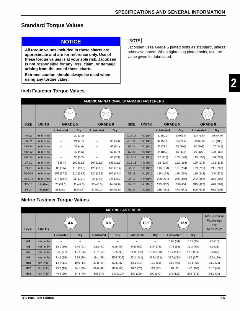
Standard Torque Values
Inch Fastener Torque Values
Metric Fastener Torque Values
NOTICE NOTEJacobsen uses Grade 5 plated bolts as standard, unless otherwise noted. When tightening plated bolts, use the value given for lubricated.
All torque values included in these charts are approximate and are for reference only. Use of these torque values is at your sole risk. Jacobsen is not responsible for any loss, claim, or damage arising from the use of these charts.
Extreme caution should always be used when using any torque value.
AMERICAN NATIONAL STANDARD FASTENERS
SIZE UNITS GRADE 5 GRADE 8 SIZE UNITS GRADE 5 GRADE 8
Lubricated Dry Lubricated Dry Lubricated Dry Lubricated Dry
#6-32 in-lb (Nm) – 20 (2.3) – – 7/16-14 ft-lb (Nm) 37 (50.1) 50 (67.8) 53 (71.8) 70 (94.9)
#8-32 in-lb (Nm) – 24 (2.7) – 30 (3.4) 7/16-20 ft-lb (Nm) 42 (56.9) 55 (74.6) 59 (80.0) 78 (105)
#10-24 in-lb (Nm) – 35 (4.0) – 45 (5.1) 1/2-13 ft-lb (Nm) 57 (77.2) 75 (101) 80 (108) 107 (145)
#10-32 in-lb (Nm) – 40 (4.5) – 50 (5.7) 1/2-20 ft-lb (Nm) 64 (86.7) 85 (115) 90 (122) 120 (162)
#12-24 in-lb (Nm) – 50 (5.7) – 65 (7.3) 9/16-12 ft-lb (Nm) 82 (111) 109 (148) 115 (156) 154 (209)
1/4-20 in-lb (Nm) 75 (8.4) 100 (11.3) 107 (12.1) 143 (16.1) 9/16-18 ft-lb (Nm) 92 (124) 122 (165) 129 (174) 172 (233)
1/4-28 in-lb (Nm) 85 (9.6) 115 (13.0) 120 (13.5) 163 (18.4) 5/8-11 ft-lb (Nm) 113 (153) 151 (204) 159 (215) 211 (286)
5/16-18 in-lb (Nm) 157 (17.7) 210 (23.7) 220 (24.8) 305 (34.4) 5/8-18 ft-lb (Nm) 128 (173) 170 (230) 180 (244) 240 (325)
5/16-24 in-lb (Nm) 173 (19.5) 230 (26.0) 245 (27.6) 325 (36.7) 3/4-10 ft-lb (Nm) 200 (271) 266 (360) 282 (382) 376 (509)
3/8-16 ft-lb (Nm) 23 (31.1) 31 (42.0) 32 (43.3) 44 (59.6) 3/4-16 ft-lb (Nm) 223 (302) 298 404 315 (427) 420 (569)
3/8-24 ft-lb (Nm) 26 (35.2) 35 (47.4) 37 (50.1) 50 (67.8) 7/8-14 ft-lb (Nm) 355 (481) 473 (641) 500 (678) 668 (905)
METRIC FASTENERS
SIZE UNITS
Non-CriticalFasteners
intoAluminum
Lubricated Dry Lubricated Dry Lubricated Dry Lubricated Dry
M4 Nm (in-lb) – – – – – – 3.83 (34) 5.11 (45) 2.0 (18)
M5 Nm (in-lb) 1.80 (16) 2.40 (21) 4.63 (41) 6.18 (54) 6.63 (59) 8.84 (78) 7.75 (68) 10.3 (910 4.0 (35)
M6 Nm (in-lb) 3.05 (27) 4.07 (36) 7.87 (69) 10.5 (93) 11.3 (102) 15.0 (133) 13.2 (117) 17.6 (156) 6.8 (60)
M8 Nm (in-lb) 7.41 (65) 9.98 (88) 19.1 (69) 25.5 (226) 27.3 (241) 36.5 (323) 32.0 (283) 42.6 (377) 17.0 (150)
M10 Nm (ft-lb) 14.7 (11) 19.6 (14) 37.8 (29) 50.5 (37) 54.1 (40) 72.2 (53) 63.3 (46) 84.4 (62) 33.9 (25)
M12 Nm (ft-lb) 25.6 (19) 34.1 (25) 66.0 (48) 88.0 (65) 94.5 (70) 125 (92) 110 (81) 147 (108) 61.0 (45)
M14 Nm (ft-lb) 40.8 (30) 54.3 (40) 105 (77) 140 (103) 150 (110) 200 (147) 175 (129) 234 (172) 94.9 (70)
4.6 8.8 10.9 12.9
4171985 First Edition 2-5

SPECIFICATIONS AND GENERAL INFORMATION
2
2.2 Air Intake and Exhaust System Specifications
2.3 Electrical Specifications
2.4 Fuel System Specifications
2.5 Cooling System Specifications
Item Unit Specification
Intake Manifold Torque lb-in. (N•m) 97 (11)
Exhaust Manifold Torque lb-in. (N•m) 204 (23)
Intake Manifold Distortion Limit in. (mm) 0.003 (0.07)
Exhaust Manifold Distortion Limit in. (mm) 0.003 (0.07)
Intake Manifold Vacuum at Idle psi (kpa) 7.7 (53)
Item Unit Specification
Spark Plug (NGK) Jacobsen PN 4119606
Spark Plug (Denso) Jacobsen PN 2701832
Spark Plug Gap in. (mm) 0.031—0.035 (0.8—0.9)
Spark Plug Torque lb-in. (N•m) 177 (20)
Firing order 1-3-2
Ignition Timing deg. / rpm 5 ± 1 / 800
ISC Duty Ratio % 5—30
O2 Sensor Feedback Duty Ratio % 5—95
Belt Deflection at Mid-Point with17 ft-lb (23 N•m) of Force Applied
Alternator Belt Deflection—New in. (mm) 0.315—0.354 (8—9)
Alternator Belt Deflection Readjustment
in. (mm) 0.472—0.59 (12—15)
Item Unit Specification
Fuel Pressure psi (kPa) 43 (294)
Item Unit Specification
Thermostat Start-to-Open °F (°C) 190 (88)
Thermostat Full Open °F (°C) 205 (96)
2-6 4171985 First Edition

SPECIFICATIONS AND GENERAL INFORMATION
2
2.6 Front Cover, Timing Chain, and Tensioner Specifications
2.7 Cylinder Head, Cams, and Valve Train Specifications
Item Unit Specification
Front Cover Torque lb-in. (N•m) 97 (11)
Item Unit Specification
Valve Clearance, Cold, Intake in. (mm) 0.007—0.009 (0.18—0.23)
Valve Clearance, Cold, Exhaust in. (mm) 0.012—0.014 (0.30—0.35)
Intake and Exhaust Manifold Mating Face Distortion Limit
in. (mm) 0.000—0.002 (0.00—0.05)
Camshaft Housing Cap Screw Torque
lb-in. (N•m) 97 (11)
Camshaft Journal Outside Diameter in. (mm) 0.903—0.904 (22.934—22.955)
Camshaft Journal Inside Diameter in. (mm) 0.905—0.906 (23.000—23.021)
Camshaft Lobe Height, Intake in. (mm) 1.477—1.483 (37.520—37.680)
Camshaft Lobe Height, Exhaust in. (mm) 1.470—1.476 (37.343—37.503)
Cylinder Head/Block Mating Face Distortion Limit
in. (mm) 0.001 (0.03)
Camshaft Oil Clearance Standard in. (mm) 0.002—0.003 (0.045—0.087)
Camshaft Oil Clearance Limit in. (mm) 0.004 (0.10)
Valve Spring Tension Standard at 1.17 in. (29.9 mm)
lb-ft (N•m) 22—26 (100—116)
Valve Spring Tension Limit at 1.17 in. (29.9 mm)
lb-ft (N•m) 20 (88)
Valve Guide to Valve Stem Clearance, Intake
in. (mm) 0.0007—0.0018 (0.020—0.047)
Valve Guide to Valve Stem Clearance Limit, Intake
in. (mm) 0.002 (0.07)
Valve Guide to Valve Stem Clearance, Exhaust
in. (mm) 0.0017—0.0028 (0.045—0.072)
Valve Guide to Valve Stem Clearance Limit, Exhaust
in. (mm) 0.003 (0.09)
Tappet and Bore Clearance in. (mm) 0.0009—0.0024 (0.025—0.062)
Tappet and Bore Clearance Limit in. (mm) 0.003 (0.10)
Valve Spring Free Length in. (mm) 1.35 (34.3)
Valve Spring Right Angle Range in. (mm) 0.000—0.059 (0.00—1.5)
Cam Cover Cap Screw Torque lb-in. (N•m) 96 (11)
Cylinder Head Cap Screw Torque lb-ft (N•m) 43.5 (59)
4171985 First Edition 2-7

SPECIFICATIONS AND GENERAL INFORMATION
2
Tappet Shim Selection Chart
Part Number Stamped Number Thickness (mm)
4148102 218 2.18
4148103 220 2.20
4148104 222 2.22
4148105 224 2.24
4148106 226 2.26
4148107 228 2.28
4148108 230 2.30
4148109 232 2.32
4148110 234 2.34
4148111 236 2.36
4148112 238 2.38
4148113 240 2.40
4148114 242 2.42
4148115 244 2.44
4148116 246 2.46
4148117 248 2.48
4148118 250 2.50
4148119 252 2.52
4148120 254 2.54
4148121 256 2.56
4148122 258 2.58
4148123 260 2.60
4148124 262 2.62
4148125 264 2.64
4148126 266 2.66
4148127 268 2.68
4148128 270 2.70
4148129 272 2.72
4148130 274 2.74
4148131 276 2.76
4148132 278 2.78
4148133 280 2.80
4148134 282 2.82
4148135 284 2.84
4148136 286 2.86
4148137 288 2.88
4148138 290 2.90
4148139 292 2.92
4148140 294 2.94
4148141 296 2.96
4148142 298 2.98
4148143 300 3.00
2-8 4171985 First Edition

SPECIFICATIONS AND GENERAL INFORMATION
2
2.8 Lubrication System Specifications
Item Unit Specification
Oil Pump Housing Torque lb-in. (N•m) 60 (6.78)
Oil Pump Outer Rotor Side Clearance Limit
in. (mm) 0.003—0.005 (0.076—0.127)
Oil Pump Radial Clearance Limit in. (mm) 0.0004—0.006 (0.10—0.15)
Inner Rotor and Pump Case Clearance
in. (mm) 0.001—0.003 (0.025—0.076)
Oil Pump Relief Valve Spring Free Length
in. (mm) 2.063 (52.40)
Oil Pump Relief Valve Spring Tension at 1.516 in (38.5: mm)of Length
lb-ft (N•m) 17.3 (4.44)
Oil Pressure Sending Unit Torque lb-in. (N•m) 115 (13)
Oil Pressure-Minimum at 4000 rpm psi (kPa) 40 (276)
Oil Pan Torque lb-in. (N•m) 97 (11)
Drain Plug Torque lb-ft (N•m) 36 (49)
Oil Filter Torque lb-in. (N•m) 120 (13.5)
Recommended Oil Normal /Cold Region
10W-30 (SH) / 5W-30 (SG)
Oil Capacity when Replacing Without Filter
qts (liters) 2.75 (2.6)
Oil Capacity when Also Replacing Filter
qts (liters) 2.96 (2.8)
Oil Change Interval—Normal Conditions
hours After First 35 Hours—Then Every 100 Hours or 3 Months
Oil Filter Replacement hours After First 35 Hours—Then Every 100 Hours or 3 Months
4171985 First Edition 2-9

SPECIFICATIONS AND GENERAL INFORMATION
2
2.9 Cylinder Block, Lower Crankcase, and Crankshaft Specifications
Item Unit Specification
Lower Crankcase (M10) Cap Screw Torque
lb-ft (N•m) 42 (57)
Lower Crankcase (M8) Cap Screw Torque
lb-in. (N•m) 212 (24)
Cylinder Bore Inside Diameter in. (mm) 2.6771—2.6779 (68.000—68.020)
Cylinder Bore Inside Diameter Limit in. (mm) 2.6791 (68.050)
Piston Outside Diameter in. (mm) 2.675—2.676 (67.970—67.990)
Oil Control Ring End Gap in. (mm) 0.0039—0.0157 (0.10—0.40)
Oil Control Ring End Gap Limit in. (mm) 0.047 (1.2)
Second Compression Ring End Gap
in. (mm) 0.0137—0.0196 (0.35—0.50)
Second Compression Ring End Gap Limit
in. (mm) 0.039 (1.0)
Top Compression Ring End Gap in. (mm) 0.0047—0.0106 (0.12—0.27)
Top Compression Ring End Gap Limit
in. (mm) 0.027 (0.7)
Cylinder Block Main Bearing Journal Inside Diameter
in. (mm) 1.9291—1.9298 (49.000—49.018)
Crankshaft Main Bearing Journal Outside Diameter
in. (mm) 1.770—1.771 (44.982—45.000)
Crankshaft/Cylinder Block Main Bearing Journal Oil Clearance
in. (mm) 0.0007—0.0015 (0.020—0.040)
Crankshaft/Cylinder Block Main Bearing Journal Oil Clearance Limit
in. (mm) 0.002 (0.065)
Piston Pin Outside Diameter in. (mm) 0.7084—0.7086 (17.995—18.000)
Piston Pin Bore Inside Diameter in. (mm) 0.7088—0.7092 (18.006—18.014)
Connecting Rod Small End Inside Diameter
in. (mm) 0.7087—0.7090 (18.003—18.011)
Connecting Rod Large End Inside Diameter
in. (mm) 1.6141—1.6148 (41.000—41.018)
Crankshaft Connecting Rod Bearing Journal Outside Diameter
in. (mm) 1.495—1.496 (37.982—38.000)
Crankshaft/Connecting Rod Oil Clearance
in. (mm) 0.0007—0.0015 (0.020—0.040)
Crankshaft/Connecting Rod Oil Clearance Limit
in. (mm) 0.002 (0.065)
Connecting Rod Torque lb-ft (N•m) 24 (33)
Crankshaft Pulley Cap Screw lb-ft (N•m) 72 (98)
Flywheel Cap Screw lb-ft (N•m) 50 (69)
Knock Sensor Torque lb-in. (N•m) 203 (23)
2-10 4171985 First Edition

SPECIFICATIONS AND GENERAL INFORMATION
2
Oversize Main Bearing Identification
Bearing Color Part Number Size Range
Brown 4140912 0.0785—0.0787 in.(1.996—2.000 mm)
Green 4140908 0.0787—0.0788 in.(1.999—2.003 mm)
Black 4140909 0.0788—0.0789 in.(2.002—2.006 mm)
No Color 4140910 0.0788—0.0789 in.(2.002—2.006 mm)
Yellow 4140911 0.0790—0.0792 in.(2.008—2.012 mm)
4171985 First Edition 2-11
SPECIFICATIONS AND GENERAL INFORMATION
2
Page Intentionally Blank
2-12 4171985 First Edition

Chapter 3
Maintenance
3
Engine Oil Level . . . . . . . . . . . . . . . . . . . . . . . . . . . . . . . . . . . . . . . . . . . . . . . . . . . . . . . . . . . . . . . 3-2
Change Engine Oil . . . . . . . . . . . . . . . . . . . . . . . . . . . . . . . . . . . . . . . . . . . . . . . . . . . . . . . . . . . . . 3-2
Oil Filter . . . . . . . . . . . . . . . . . . . . . . . . . . . . . . . . . . . . . . . . . . . . . . . . . . . . . . . . . . . . . . . . . . . . . . 3-2Replacement . . . . . . . . . . . . . . . . . . . . . . . . . . . . . . . . . . . . . . . . . . . . . . . . . . . . . . . . . . . . . 3-2
Spark Plugs . . . . . . . . . . . . . . . . . . . . . . . . . . . . . . . . . . . . . . . . . . . . . . . . . . . . . . . . . . . . . . . . . . 3-3Replacement . . . . . . . . . . . . . . . . . . . . . . . . . . . . . . . . . . . . . . . . . . . . . . . . . . . . . . . . . . . . . 3-3
4171985 First Edition 3-1

MAINTENANCE
3
Engine Oil LevelSee Figure 3-1.
Figure 3-1
1. Park the vehicle on a level surface.
2. Operate the engine until normal operating temperature is reached.
3. Stop the engine. Remove dipstick (3) and wipe clean. Install and remove dipstick again.
4. Check engine oil level.
If oil level is at or below low mark (1), add oil until the level reaches the full mark (2).
5. Install dipstick (3).
Change Engine OilSee Figure 3-2.
Figure 3-2
1. Park the vehicle on a level surface.
2. Operate the engine until normal operating temperature is reached.
3. Stop the engine and place a suitable pan under the engine.
! WARNING
4. Remove drain plug (1) with seal (2) and drain engine oil.
NOTEAlways use new O-rings, gaskets, and seals.
5. Install drain plug (1) using new seal (2). Tighten to specification.
Drain Plug Torque: 36 lb-ft (49 N•m)
6. Add new engine oil through cylinder head cover until oil level reaches full mark on dipstick.
Engine Oil Capacity: 2.9 qt (2.7 L) without oil filter
7. Start engine and check for leaks.
8. Stop engine and check engine oil level. Top off as needed.
Oil Filter
ReplacementSee Figures 3-3 and 3-4.
Figure 3-3
1. Drain engine oil.
TN0533
1 2
3
TN0534
1
2
The engine oil will be hot. Avoid skin contact with used engine oil.
Required Tools
Oil Filter Wrench (Suzuki PN 09915-47340)
1
TN0694
3-2 4171985 First Edition

MAINTENANCE
3
2. Using oil filter wrench, remove the oil filter (1).
Figure 3-4
3. Coat new oil filter O-ring (2) with clean engine oil.
NOTEPrevent contamination; clean oil filter housing before installing new oil filter.
4. Install new oil filter and tighten to specification.
Oil Filter Tightening Torque: 120 lb-in. (13.5 N•m)
5. Fill engine oil.
Oil Capacity with Filter: 3.1 qt (2.9 L)
Spark Plugs
ReplacementSee Figures 3-5 through 3-7.
Figure 3-5
1. Remove cap screws (1).
2. Remove ignition coils (2).
Figure 3-6
3. Remove spark plugs (3).
Figure 3-7
4. Set gap (5) on each new spark plug (4) to specification.
Spark Plug Gap: 0.032—0.035 in. (0.8—0.9 mm)
5. Install new spark plugs, tighten to specification.
Spark Plug Tightening Torque: 177 lb-in. (20 N•m)
6. Install ignition coils.
2
TN0352
TN0695
1
2
TN0697
3
45
TN0698
4171985 First Edition 3-3
MAINTENANCE
3
Page Intentionally Blank
3-4 4171985 First Edition

Chapter 4
Theory of Operation
4
4.1 General Engine Operation . . . . . . . . . . . . . . . . . . . . . . . . . . . . . . . . . . . . . . . . . . . . . . . . . 4-2
4.2 Air Intake, Fuel, and Exhaust . . . . . . . . . . . . . . . . . . . . . . . . . . . . . . . . . . . . . . . . . . . . . . . 4-4
4.3 Cooling System . . . . . . . . . . . . . . . . . . . . . . . . . . . . . . . . . . . . . . . . . . . . . . . . . . . . . . . . . . 4-5Thermostat . . . . . . . . . . . . . . . . . . . . . . . . . . . . . . . . . . . . . . . . . . . . . . . . . . . . . . . . . . . . . . 4-6Water Pump . . . . . . . . . . . . . . . . . . . . . . . . . . . . . . . . . . . . . . . . . . . . . . . . . . . . . . . . . . . . . 4-6
4.4 Front Cover, Timing Chain, and Tensioner . . . . . . . . . . . . . . . . . . . . . . . . . . . . . . . . . . . . 4-7Front Cover . . . . . . . . . . . . . . . . . . . . . . . . . . . . . . . . . . . . . . . . . . . . . . . . . . . . . . . . . . . . . . 4-8Timing Chain . . . . . . . . . . . . . . . . . . . . . . . . . . . . . . . . . . . . . . . . . . . . . . . . . . . . . . . . . . . . . 4-8Tension Adjuster . . . . . . . . . . . . . . . . . . . . . . . . . . . . . . . . . . . . . . . . . . . . . . . . . . . . . . . . . . 4-8
4.5 Cylinder Head and Valve Train . . . . . . . . . . . . . . . . . . . . . . . . . . . . . . . . . . . . . . . . . . . . . . 4-9Head Gasket . . . . . . . . . . . . . . . . . . . . . . . . . . . . . . . . . . . . . . . . . . . . . . . . . . . . . . . . . . . . 4-10Camshaft . . . . . . . . . . . . . . . . . . . . . . . . . . . . . . . . . . . . . . . . . . . . . . . . . . . . . . . . . . . . . . . 4-10
4.6 Lubrication System . . . . . . . . . . . . . . . . . . . . . . . . . . . . . . . . . . . . . . . . . . . . . . . . . . . . . . 4-11
4.7 Cylinder Block and Lower Crankcase . . . . . . . . . . . . . . . . . . . . . . . . . . . . . . . . . . . . . . . 4-13Crankshaft . . . . . . . . . . . . . . . . . . . . . . . . . . . . . . . . . . . . . . . . . . . . . . . . . . . . . . . . . . . . . . 4-13Connecting Rod . . . . . . . . . . . . . . . . . . . . . . . . . . . . . . . . . . . . . . . . . . . . . . . . . . . . . . . . . . 4-14Piston, Piston Rings, and Piston Pin . . . . . . . . . . . . . . . . . . . . . . . . . . . . . . . . . . . . . . . . . . 4-14
4171985 First Edition 4-1

THEORY OF OPERATION
4
4.1 General Engine OperationSee Figure 4-1.
Figure 4-1
The K6A engine is an in-line, 3-cylinder, twin overhead cam, 4-valve per cylinder, naturally aspirated, liquid cooled, gasoline engine.
The compact K6A engine is constructed primarily of durable, lightweight, heat-dissipating materials.
The cylinder head is a twin cam 4-valve type and made of aluminum alloy that is light in weight and excellent in heat dissipation. Valves are direct driven from camshafts by way of shim-adjustable tappets placed on top of valves.
The combustion chamber is a pent-roof type with the spark plug arranged in the center for improved combustion. Spark plugs are fired by direct mounted individual coils for each plug.
The camshafts are made of lightweight hollow cast iron. Camshaft drive is done with a chain drive that is automatically adjusted by a chain tensioner. The chain tensioner uses lubrication system pressure and spring pressure to automatically compensate for chain wear.
The cylinder head gasket is of 2-layer laminated stainless steel which is excellent in durability and reliability. Use of advanced coatings further enhance the fluid sealing capabilities of the gasket.
The cylinder block is of a lightweight aluminum two-piece design, consisting of upper and lower castings. The lower casting is a ladder design that incorporates the main journal caps for added rigidity. Semi-wet pressed-in cylinder sleeves are contained in the upper block casting.
The crankshaft is constructed of cast iron and utilizes four main journals and three rod journals. Counter- balancing is achieved by weights on two of the journals. Rod and main journal bearings are of a two-piece design with the third main journal incorporating a thrust bearing.
Connecting rods are of a two-piece design made of carbon steel. The rod cap is retained, using special reamer type rod bolts and nuts.
TN0746
4-2 4171985 First Edition

THEORY OF OPERATION
4
Pistons attached to connecting rods are made of an aluminum alloy and use a full-floating piston pin. Piston pin holes are equipped with a “Ricardo Groove” to aid in lubrication. Pistons incorporate a slipper skirt with three rings: two compression and one oil type.
The engine lubrication system incorporates a lightweight aluminum oil pan with internal crankshaft baffle. Engine oil is removed from the pan through a strainer pickup by a crankshaft driven oil pump with integral oil pressure regulator. Engine oil is routed through a full-flow oil filter that houses an internal filter bypass valve and then distributed throughout the engine.
A belt-driven water pump removes coolant from a full-flow radiator and circulates the coolant through the entire engine. The coolant temperature is controlled by the cylinder-head-mounted thermostat housing containing the thermostat.
The electronically controlled fuel injection system efficiently supplies fuel to the engine, while maintaining optimum performance and throttle response. Port injectors with a common fuel rail in conjunction with a throttle body are used for fuel distribution.
4171985 First Edition 4-3

THEORY OF OPERATION
4
4.2 Air Intake, Fuel, and ExhaustSee Figure 4-2.
Figure 4-2
Fuel is supplied from the fuel rail (2) to each cylinder via electronically controlled fuel injectors (1), mounted to the intake manifold (3) runners.
Air flow into the intake manifold is metered with a throttle body assembly (4), which is fastened and sealed to the intake manifold. The throttle body is controlled and monitored by the ECM to adjust fuel/air mixtures.
Exhaust gases are expelled through the exhaust side of the cylinder head into the exhaust manifold (5), which is fastened and sealed to the cylinder head. Exhaust gases are monitored with the oxygen sensor (6), which provides the ECM with data to adjust fuel/air mixtures. The entire exhaust manifold is surrounded by a heat shield (7) to aid in prevention of accidental burns.
1 Injector (3 used) 5 Exhaust Manifold2 Fuel Rail 6 Oxygen Sensor3 Intake Manifold 7 Heat Shield4 Throttle Body Assembly
TN0690
1
2 3
4
5
6
7
4-4 4171985 First Edition

THEORY OF OPERATION
4
4.3 Cooling SystemSee Figure 4-3.
Figure 4-3
The cooling system includes the radiator (4), water pump (5), thermostat (7), and engine coolant passages.
Coolant is circulated from the water pump (5) into the engine coolant passages and circulates around the cylinders. From the cylinders, coolant flows up through the block deck passages and into the cylinder head (2). In the cylinder head (2), the coolant flows through passages around the intake and exhaust ports, valve seats, and combustion chambers. Coolant flows toward the rear of the cylinder head (2) and exits through the thermostat housing (8).
During the warm-up period, the thermostat (7) is closed and coolant flows only through the jiggle pin (1) opening to provide a fast warm-up period. The jiggle pin (1) also helps ensure that no air is trapped in the engine when filling the cooling system.
Once the engine has reached operating temperature, the thermostat (7) opens and allows coolant to flow through the upper radiator hose to the radiator (4) top tank.
Coolant circulates through the radiator (4), dissipates heat, and then flows out of the radiator (4) through the lower hose and into the suction side of the water pump (5).
If coolant temperature begins to become excessive, the radiator pressure cap will open and allow excess coolant to flow into the overflow bottle (3). When coolant temperature lowers enough, the radiator cap will close. As the coolant continues to cool, a vacuum will be created in the radiator (4). This will open a valve in the radiator cap that will syphon the excess coolant from the overflow bottle (3) back into the radiator (4).
Coolant continues flowing through the engine and radiator circuit until the coolant temperature drops below the thermostat (7) opening temperature. The thermostat (7) will remain open until coolant temperature falls below the thermostat closing temperature. At that time the thermostat (7) will close and begin a new cycle of warming the coolant.
This repeated cycle of temperature control keeps the engine at the optimal temperature for clean and efficient performance.
1 Jiggle Pin 5 Water Pump2 Cylinder Head 6 Cylinder Block3 Overflow Bottle 7 Thermostat4 Radiator 8 Thermostat Housing
4
56
7
8
1
32
4171985 First Edition 4-5

THEORY OF OPERATION
4
ThermostatSee Figure 4-4.
Figure 4-4
The cooling system thermostat (1) is contained in the thermostat housing located on the rear of the cylinder head. The thermostat controls the flow of coolant through the engine. The thermostat is in the closed position when the engine is cold. When coolant temperature reaches 190° F (88° C) the thermostat begins to open, allowing coolant to circulate. The thermostat opens fully when coolant temperature reaches 205° F (96° C), allowing full coolant system circulation. As engine load is varied, the thermostat will vary its open or closed percentage to maintain the engine in an optimum temperature range. A jiggle pin is provided in the thermostat to aid in the bleeding of the system when filling.
Water PumpSee Figure 4-5.
Figure 4-5
The engine is equipped with a belt-driven water pump (1) driven from the crankshaft pulley. The water pump circulates coolant throughout the entire cooling system. The water pump is equipped with a “weep hole” for indication of seal wear. The pump is serviceable as a unit only.
TN0573
1
TN0747
1
4-6 4171985 First Edition

THEORY OF OPERATION
4
4.4 Front Cover, Timing Chain, and TensionerSee Figure 4-6.
Figure 4-6
Attached to the front of the engine is the one-piece cast aluminum front cover. The front cover attaches the oil pump pickup strainer and houses the oil pump and front seal. Contained under the front cover is the timing chain, chain guide, and chain tensioner setup.
1 Crankshaft Pulley 6 Tension Adjuster2 Front Cover 7 Chain Guide3 Tensioner Link 8 Crankshaft Sprocket4 Tensioner 9 Oil Pump5 Timing Chain 10 Pickup Strainer
TN0748
1
23 4
56
7
8
9
10
4171985 First Edition 4-7

THEORY OF OPERATION
4
Front CoverSee Figure 4-7.
Figure 4-7
The front cover (1) houses the crankshaft-driven oil pump (2) and front seal (3). Attached to the bottom of the cover is the pickup strainer (4) for the oil pump.
Timing ChainSee Figure 4-8.
Figure 4-8
For the camshaft drive, a highly durable chain drive system is used.
Through the timing chain (1), the crankshaft rotation is transmitted from the crankshaft timing sprocket (7) to the camshaft timing sprockets (2 and 5) installed on the end of the intake and exhaust camshafts.
The timing chain has aligning links (3, 4, and 8) that are used for aligning with the timing marks on the respective camshaft sprockets and crankshaft sprocket.
A chain guide (6) and chain tensioner (9) system are used to ensure quiet and accurate operation.
Tension AdjusterSee Figure 4-9.
Figure 4-9
The tension adjuster (6) has a plunger (4) inside, which pushes against the tensioner link to give proper tension. This plunger is operated by engine oil pressure (1) as well as spring tension (3). The plunger is designed to travel in only one way. Once the plunger has moved outward, it will not come back due to the function of the ratcheting mechanism (5).
There is a check ball (2) inside the plunger (4), which keeps hydraulic pressure from dropping. With this provision, the plunger can resist and absorb a kickback force. During operation under low oil pressure, the ratchet keeps the plunger from being pushed back, allowing tension of the chain to be maintained. The result is quiet operation without chain flapping.
TN0749
1
4
23
TN0502
1
2
3 4
5
6
7
8
9
TN0503
12
3
4
56
4-8 4171985 First Edition

THEORY OF OPERATION
4
4.5 Cylinder Head and Valve TrainSee Figure 4-10.
Figure 4-10
The twin cam, 4-valve per cylinder head is constructed with an aluminum alloy that is both lightweight and efficient in heat dissipation. Valve angle is set narrow to also make for a compact head design.
The spark plug port (12) is located in the center of the combustion chamber, with the combustion chamber being a pent-roof design for improved combustion efficiency.
The intake (11) and exhaust ports (13) are arranged in a cross-flow style with each cylinder having two intake and two exhaust valves for improved intake and exhaust efficiency. Intake valves are faced with a dual angle while exhaust valves have a single angle face.
The valve spring retainer (5), valve spring (6), valve seal (7), and valve spring seat (8) are all installed over the valve stem and held in place with the retainer locks (4).
The valves (9 and 10) are pushed down directly with the camshaft lobe (1) via shim (2) and tappet (3). Valve lash is adjusted by varying the thickness of the shim (2).
1 Camshaft Lobe 6 Valve Spring 11 Intake Port2 Shim 7 Valve Seal 12 Spark Plug Port3 Tappet 8 Valve Spring Seat 13 Exhaust Port4 Retainer Lock 9 Intake Valve5 Valve Spring Retainer 10 Exhaust Valve
TN0750, 0523, 0493
1
2
3
6
7
8
9
4
13
12
11 10
5
4171985 First Edition 4-9

THEORY OF OPERATION
4
Head GasketSee Figure 4-11.
Figure 4-11
The cylinder head gasket is made of a 2-layer laminated stainless steel. The surface of the cylinder head gasket is treated with a rubberized coating.
CamshaftSee Figure 4-12.
Figure 4-12
The intake (1) and exhaust (2) camshafts are made of lightweight hollow cast iron. The camshaft timing sprockets (3) are press fit onto the front of the camshafts and are serviceable only with the camshaft. Engine oil flows through the hollow center of the cams, direct lubricating the camshaft journals. Camshaft lobes, tappets, and valves are indirect splash lubricated from the camshaft journals.
TN0494
TN0505
12
3
4-10 4171985 First Edition

THEORY OF OPERATION
4
4.6 Lubrication SystemSee Figure 4-13.
Figure 4-13
The K6A engine uses a wet sump lubrication system, which force feeds oil through the full-flow oil filter and the entire lubrication system.
The inner rotor of the oil pump is driven by the crankshaft. The outer rotor is driven with the inner rotor. The pump creates suction, and draws oil through the oil pickup strainer from the oil pan. The oil is pumped through the main passage of the front cover into the engine block and the oil filter.
An oil pressure switch is located in this passage to monitor and warn of low oil pressure.
The oil is routed through a full-flow oil filter equipped with a bypass valve. The bypass valve will open and allow oil flow to the engine in the event the filter becomes plugged or damaged and will not allow oil flow to the engine. From the filter, the oil flows into the main gallery. The main gallery sends oil to both the cylinder block and the cylinder head.
OIL PRESSURESWITCH BYPASS VALVE
LUBE OIL FILTER
CYLINDER BLOCK MAIN GALLERY.
REGULATORVALVE
LUBE OIL PUMP
OIL SUCTION PIPE(STRAINER)
TENSIONADJUSTER
TIMINGCHAIN
FRONT CAMJOURNAL
CAMSHAFT
CAM JOURNALS
CAM FACETAPPETS,
PISTON PIN
CONNECTINGROD
RODJOURNALS
ROD PIN
CRANK PIN
CRANKJOURNALS
OIL PAN
VALVES
TN0751
4171985 First Edition 4-11

THEORY OF OPERATION
4
From the main gallery, oil distributes to the crankshaft journals and crank pins. The crankshaft is drilled between the crank pins and rod pins. Oil flows through to the rod pins, lubricating the rod journals, and then passes into a drilled passage in the connecting rod. Oil also seeps out the sides of the crank and rod journals to lubricate the sides of the journals. Any excess oil from lubricating the crank and rod journals passes out from the journals and returns to the oil pan.
The passage in the connecting rod leads to an oil jet at the top of the large end of the rod.This jet sprays oil upward to lubricate the cylinder walls, piston, and piston pin. Excess oil drains back to the oil pan.
Oil from the main gallery is also sent up to the cylinder head. On its way up to the cylinder head, the oil passes through a restrictor orifice. This limits the amount of oil to the head and ensures the proper amount of oil in the lower end of the engine.
When the oil reaches the cylinder head, the passage splits. Oil is sent to the timing chain tension adjuster to maintain proper chain tension. An orifice in the tension adjuster also provides a spray to lubricate the timing chain.
The oil is also sent up to the front of the cylinder head, where it lubricates both of the front camshaft journals. Oil enters both camshafts from the front journals and flows through the camshafts, where it exits lube holes for each of the other camshaft journals. Excess oil exits the journals and splash lubricates the camshaft faces and tappets. Oil seeps through oil holes in the tappet adjusting shims and tappets to lubricate the valves.
Excess oil then flows through return passages from the cylinder head and returns to the oil pan.
4-12 4171985 First Edition

THEORY OF OPERATION
4
4.7 Cylinder Block and Lower CrankcaseSee Figure 4-14.
Figure 4-14
The cylinder block (1) is made of a lightweight aluminum alloy. The cylinders contain press-fit, semi-wet style liners for improved cooling and reliability.
The lower crankcase (2) is made of lightweight aluminum alloy. The journal bearing caps are integrated into the casting, which makes it possible to reduce weight, improve rigidity, and suppress vibrating noise.
CrankshaftSee Figure 4-15.
Figure 4-15
The crankshaft (1) is constructed of cast iron. The crankshaft has four main bearing journals and three rod bearing journals, and is counterbalanced on rod throws 1 and 3 to reduce vibration. Each main journal contains a two-piece main bearing (4 and 5), which is lubricated via an oil hole (3). The third main journal contains a thrust bearing (2). The front-mounted timing sprocket drives both the timing chain and oil pump inner rotor. The crankshaft pulley is equipped with a damper to reduce vibration.
TN0496
1
2
TN0497, 0498
3
45
1
2
4171985 First Edition 4-13

THEORY OF OPERATION
4
Connecting RodSee Figure 4-16.
Figure 4-16
The connecting rod is made of carbon steel with an H-shaped cross section. The rod consists of two pieces, the main beam (1) and the rod cap (3), which is fastened with special reamer type rod bolts and nuts. The small end of the rod is machined for a full-floating piston pin. An oil jet (2) lubricates the cylinder wall, piston, and piston pin. The rod bearings (4) are made of an aluminum alloy.
Piston, Piston Rings, and Piston PinSee Figures 4-17 and 4-18.
Figure 4-17
Figure 4-18
The three-ring, skirt-type, full-floating pistons (1) are made of an aluminum alloy. The pistons are equipped with intake valve reliefs (2) machined into the face. The piston pin bores are equipped with “Ricardo Grooves” (3) to aid in lubrication. The piston is assembled in the engine with the floating-fit piston pin for lower friction.
All piston rings are located above the piston pin. The two top rings are compression rings and the 3rd (6) is an oil ring.
The 1st ring (4) is of barrel face type designed for improved initial breaking in. The 2nd ring (5) is of taper undercut type designed for better oil scraping performance. A hard chrome is plated on the circumference of the 1st ring for extended durability.
TN0499
1 2
3
4
TN0527
12
3
TN0529
5
4
6
4-14 4171985 First Edition

Chapter 5
Tests and Adjustments
5
5.1 Air Intake and Exhaust Systems . . . . . . . . . . . . . . . . . . . . . . . . . . . . . . . . . . . . . . . . . . . . 5-2Intake Manifold Vacuum Test . . . . . . . . . . . . . . . . . . . . . . . . . . . . . . . . . . . . . . . . . . . . . . . . 5-2PCV Valve/Hose Test . . . . . . . . . . . . . . . . . . . . . . . . . . . . . . . . . . . . . . . . . . . . . . . . . . . . . . 5-2
5.2 Cooling System . . . . . . . . . . . . . . . . . . . . . . . . . . . . . . . . . . . . . . . . . . . . . . . . . . . . . . . . . . 5-3Thermostat Test . . . . . . . . . . . . . . . . . . . . . . . . . . . . . . . . . . . . . . . . . . . . . . . . . . . . . . . . . . 5-3
5.3 Cylinder Head, Cams, and Valve Train . . . . . . . . . . . . . . . . . . . . . . . . . . . . . . . . . . . . . . . 5-3Valve Clearance Check and Adjustment . . . . . . . . . . . . . . . . . . . . . . . . . . . . . . . . . . . . . . . . 5-3Cylinder Compression Test . . . . . . . . . . . . . . . . . . . . . . . . . . . . . . . . . . . . . . . . . . . . . . . . . . 5-6
5.4 Lubrication System . . . . . . . . . . . . . . . . . . . . . . . . . . . . . . . . . . . . . . . . . . . . . . . . . . . . . . . 5-7Oil Pressure Test . . . . . . . . . . . . . . . . . . . . . . . . . . . . . . . . . . . . . . . . . . . . . . . . . . . . . . . . . . 5-7
4171985 First Edition 5-1

TESTS AND ADJUSTMENTS
5
5.1 Air Intake and Exhaust Systems
Intake Manifold Vacuum TestSee Figure 5-1.
1. Warm up the engine.
Figure 5-1
2. Stop the engine.
3. Remove hose (2) from PCV valve and install vacuum gauge (1) to PCV hose (2).
NOTESCap or plug PCV valve.
Place transmission in neutral position.
4. Start the engine. Measure the intake manifold vacuum at idle.
Intake Manifold Vacuum at Idle: At least 7.7 psi (53 kPa)
5. Stop the engine. Remove the vacuum gauge and install the PCV hose.
PCV Valve/Hose TestSee Figures 5-2 and 5-3.
Figure 5-2
1. Remove the PCV valve (1) from the cylinder head cover.
2. Start engine and bring to idle. Block the end opening of PCV valve. Suction (vacuum) should be detected.
3. If any abnormal condition is found, replace the PCV valve and hose.
Figure 5-3
4. Remove the PCV valve and verify the internal check ball can be heard when shaking the valve.
5. If any abnormal condition or restriction is found, replace the PCV valve and hose.
Required Tools
Vacuum Gauge: Suzuki PN 09915-67311 or Equivalent
TN0538
2
1
TN0598
1
TN0599
5-2 4171985 First Edition

TESTS AND ADJUSTMENTS
5
5.2 Cooling System
Thermostat TestSee Figures 5-4 and 5-5.
Figure 5-4
1. Check that the air bleed valve (1) of thermostat is not blocked.
2. Inspect valve seat (2) for any substance that could interfere with sealing.
Figure 5-5
3. Immerse the thermostat (4) in water and heat it gradually with an appropriate heater (5).
4. Observe thermometer (3) to verify that the thermostat opens at the specified temperature. Replace thermostat if not to specifications.
Thermostat Start-to-Open Temperature:190°F (88°C)
Full Open Temperature: 205°F (96°C)
5.3 Cylinder Head, Cams, and Valve Train
Valve Clearance Check and AdjustmentSee Figures 5-6 through 5-13.
Check
Figure 5-6
1. Remove the cam cover (1). (See “Cam Cover” on page 7-17.)
Figure 5-7
2. Turn the crankshaft clockwise as viewed from front.
TN0429
1
2
TN0430
3
4
5
Valve Clearance Intake Exhaust
Cold 0.007—0.009 in.(0.18—0.23 mm)
0.012—0.014 in.(0.30—0.35 mm)
TN0539
1
TN0540
4171985 First Edition 5-3

TESTS AND ADJUSTMENTS
5
IMPORTANTThe check and adjustment must be performed when engine is cold.
Continue turning the crankshaft so that each different cam lobe will point away from the shim face successively. Measure each valve clearance at this position. (All the valve clearances can be measured during two complete turns of crankshaft.)
Valve clearance and adjustment may be done in pairs (Example: #1 Intake valves, then #2 Intake valves, and so on.)
The valve clearance measurement must be performed with the timing chain installed in place.
Figure 5-8
3. When the cam lobe (2) to be checked points 180° away from the shim face, measure the clearance between the camshaft and shim using a feeler gauge (3).
4. Check measurement against valve clearance specification.
5. Perform adjustment procedure if valve clearance is out of specification.
Adjustment
Figure 5-9
1. If the valve clearance is out of specification, adjust it by replacing the shim (1).
2. Ensure that the valve is closed for the shim being adjusted and turn the tappet to bring its cutaway (2) inward.
3. Turn the crankshaft to open the valve needing adjustment.
Figure 5-10
4. Remove the camshaft housing cap screws (3).
NOTEThe special tool stamped with “IN” must be used for intake camshaft and tool with “EX” for exhaust camshaft.
Check that the special tool is not pushing on the shim.
5. Attach the special tool (4) with the camshaft housing cap screws. Torque to specification.
Tightening Torque: 97 lb-in. (11 N•m)
Required Tools
Tappet Holder: Jacobsen PN 4139726
TN0360
180°2
3
TN03612
1
TN0362
3 4
5-4 4171985 First Edition

TESTS AND ADJUSTMENTS
5
Figure 5-11
6. Turn the camshaft clockwise until the cam lobe is 180° away from the tappet and remove the shim (5) from the tappet by lifting at the cutaway.
Figure 5-12
7. Measure the thickness of the removed shim, and determine the required thickness of the new shim using the following equation:
IMPORTANTIf the value “A” equals an odd number, use a shim 0.01 smaller than “A” value.
Shim Selection Chart
TN0363
5
TN0364
A = B + (C – 0.20 mm)
Where A: Required thickness of new shim (mm)
B: Thickness of removed shim (mm)
C: Valve clearance measured (mm)
Part NumberStamped Number
Thickness (mm)
4148102 218 2.18
4148103 220 2.20
4148104 222 2.22
4148105 224 2.24
4148106 226 2.26
4148107 228 2.28
4148108 230 2.30
4148109 232 2.32
4148110 234 2.34
4148111 236 2.36
4148112 238 2.38
4148113 240 2.40
4148114 242 2.42
4148115 244 2.44
4148116 246 2.46
4148117 248 2.48
4148118 250 2.50
4148119 252 2.52
4148120 254 2.54
4148121 256 2.56
4148122 258 2.58
4148123 260 2.60
4148124 262 2.62
4148125 264 2.64
4148126 266 2.66
4148127 268 2.68
4148128 270 2.70
4148129 272 2.72
4148130 274 2.74
4148131 276 2.76
4148132 278 2.78
4148133 280 2.80
4148134 282 2.82
4171985 First Edition 5-5

TESTS AND ADJUSTMENTS
5
NOTEInstall the shim with its size marking facing tappet.
8. Install the selected shim with its stamped number facing tappet side.
Figure 5-13
IMPORTANTIf the crankshaft is turned in the normal direction (turning the cam lobe clockwise), the valve may possibly hit the piston head.
9. Turn camshaft counterclockwise until cam lobe has fully opened the valve.
10. Remove special tappet tool and reinstall cam housing cap screws.
11. Tighten the camshaft housing cap screws to specification
Camshaft Housing Cap Screws Torque: 97 lb-in. (11 N•m)
NOTICE
Installation Note
For installation procedure, reverse the sequence of removal.
Cylinder Compression TestSee Figure 5-14.
1. Warm up the engine.
2. Stop the engine, remove all the spark plugs and disconnect the cam angle sensor coupler.
Figure 5-14
3. Install the special tools (1, 2, and 3) to the spark plug hole being checked.
4. With the throttle fully open, operate the starter motor and check the maximum reading on the compression gauge.
4148135 284 2.84
4148136 286 2.86
4148137 288 2.88
4148138 290 2.90
4148139 292 2.92
4148140 294 2.94
4148141 296 2.96
4148142 298 2.98
4148143 300 3.00
Part NumberStamped Number
Thickness (mm)
TN0365
6
After completing the valve clearance adjustment, check the clearance again to make sure it is within the specification.
Required Tools
Compression Gauge Set: Suzuki PN 09916-67011 or EquivalentCompression Gauge Hose: Suzuki PN 09915-64530 or EquivalentCompression Gauge Hose Attachment B: Suzuki PN 09915-64550 or Equivalent
1 Compression Gauge Set
3 Compression Gauge Hose Attachment
2 Compression Gauge Hose
TN0537
3
12
5-6 4171985 First Edition

TESTS AND ADJUSTMENTS
5
NOTICE
5. Carry out steps 3 and 4 above on all the cylinders.
6. If the compression pressure is lower than the limit, check that the special tool is properly installed. If the installed condition is correct, the possible cause may be compression leak from piston ring or valve.
7. After completing the inspection, install the spark plugs and connect cam angle sensor.
5.4 Lubrication System
Oil Pressure TestSee Figures 5-15 through 5-17.
1. Check that the following items are satisfactory.
• Oil Level Refill
• Oil Contamination Replace
• Oil Leakage Repair
Figure 5-15
2. Remove the oil pressure sending unit from the cylinder block. (See “Oil Pressure Sending Unit” on page 7-32.)
3. Install the special tools (1 and 2) into the oil pressure sending unit hole.
4. Warm up the engine.
Figure 5-16
5. Raise engine speed to 4000 rpm and measure the oil pressure on the gauge (3).
Oil Pressure—Minimum at 4,000 rpm: 40 psi (276 kPa)
6. If the oil pressure measurement is out of specification, check the oil pump and oil filter.
Compression Pressure at 400 rpm
Standard: psikPa (kgf/cm²)
178.41,230 (12.5)
Service limit psikPa (kgf/cm²)
134.9930 (9.5)
Difference Between CylindersMaximum
psikPa (kgf/cm²)
14.298 (1.0)
If the specified speed (400 rpm) is not attainable due to lowered battery voltage, recharge the battery and carry out the inspection again.
Required Tools
Oil Pressure Gauge: Suzuki PN 09915-77311 or Equivalent
Oil Pressure Gauge Attachment: Suzuki PN 09915-78211 or Equivalent
TN0536
1
2
TN0353
3
4171985 First Edition 5-7

TESTS AND ADJUSTMENTS
5
Figure 5-17
7. After completing the inspection, remove the special tools. Wrap teflon tape (4) on the oil pressure sending unit (5) threads and tighten it to specification.
Oil Pressure Sending Unit Torque: 115 lb-in. (13 N·m)
8. Start the engine and check oil pressure switch for leaks.
TN0355
5
4
5-8 4171985 First Edition

Chapter 6
Diagnostic Troubleshooting
6
Troubleshooting . . . . . . . . . . . . . . . . . . . . . . . . . . . . . . . . . . . . . . . . . . . . . . . . . . . . . . . . . . . . . . . 6-2Engine Starts Hard (But Cranks Properly). . . . . . . . . . . . . . . . . . . . . . . . . . . . . . . . . . . . . . . 6-2Poor Idling . . . . . . . . . . . . . . . . . . . . . . . . . . . . . . . . . . . . . . . . . . . . . . . . . . . . . . . . . . . . . . . 6-2Insufficient Engine Power. . . . . . . . . . . . . . . . . . . . . . . . . . . . . . . . . . . . . . . . . . . . . . . . . . . . 6-2Engine Surges or Misses. . . . . . . . . . . . . . . . . . . . . . . . . . . . . . . . . . . . . . . . . . . . . . . . . . . . 6-3Poor Throttle Response. . . . . . . . . . . . . . . . . . . . . . . . . . . . . . . . . . . . . . . . . . . . . . . . . . . . . 6-3Engine Overheats. . . . . . . . . . . . . . . . . . . . . . . . . . . . . . . . . . . . . . . . . . . . . . . . . . . . . . . . . . 6-3Excessive Fuel Consumption. . . . . . . . . . . . . . . . . . . . . . . . . . . . . . . . . . . . . . . . . . . . . . . . . 6-4Excessive Oil Consumption. . . . . . . . . . . . . . . . . . . . . . . . . . . . . . . . . . . . . . . . . . . . . . . . . . 6-4Low Oil Pressure. . . . . . . . . . . . . . . . . . . . . . . . . . . . . . . . . . . . . . . . . . . . . . . . . . . . . . . . . . 6-4Excessive Engine Noise. . . . . . . . . . . . . . . . . . . . . . . . . . . . . . . . . . . . . . . . . . . . . . . . . . . . . 6-5White Exhaust Smoke. . . . . . . . . . . . . . . . . . . . . . . . . . . . . . . . . . . . . . . . . . . . . . . . . . . . . . 6-5Excessive Engine Vibration. . . . . . . . . . . . . . . . . . . . . . . . . . . . . . . . . . . . . . . . . . . . . . . . . . 6-5
4171985 First Edition 6-1

DIAGNOSTIC TROUBLESHOOTING
6
Troubleshooting
Condition Probable Cause Remedy
Engine starts hard (but cranks properly). Fouled spark plug(s). Check spark plugs. (See “Spark Plugs” on page 7-8.)
Faulty ignition coil. Check ignition coils. (See “Ignition Coils” on page 7-8.)
Faulty fuel injector. Check fuel injectors. (See “Injectors” on page 7-9.)
Throttle body gasket leaking air. Check throttle body and gasket. (See “Throttle Body” on page 7-4.)
Faulty ISC (idle speed control) valve. Check ISC (idle speed control) valve. (See “ISC (Idle Speed Control) Valve” on page 7-3.)
Faulty throttle position sensor. Check throttle position sensor. (See “Throttle Position Sensor” on page 7-3.)
Faulty manifold pressure sensor. Check pressure sensor.(See “Pressure Sensor” on page 7-3.)
Intake manifold leaking air. Check intake manifold and gasket. (See “Intake Manifold” on page 7-4.)
Exhaust restriction. Check exhaust manifold. (See “Exhaust Manifold” on page 7-7.)
Poor idling. Fouled spark plug(s). Check spark plugs. (See “Spark Plugs” on page 7-8.)
Faulty ignition coil. Check ignition coils. (See “Ignition Coils” on page 7-8.)
Faulty oxygen sensor. Check oxygen sensor. (See “Oxygen Sensor” on page 7-6.)
Faulty ISC (idle speed control) valve. Check ISC (idle speed control) valve. (See “ISC (Idle Speed Control) Valve” on page 7-3.)
Valve clearance adjustment. Check valve clearance. (See “Valve Clearance Check and Adjustment” on page 5-3.)
Faulty valve spring. Check valve springs. (See “Valves” on page 7-27.)
Insufficient engine power. Fouled spark plug(s). Check spark plugs. (See “Spark Plugs” on page 7-8.)
Faulty ignition coil. Check ignition coils. (See “Ignition Coils” on page 7-8.)
Faulty fuel injector. Check fuel injectors. (See “Injectors” on page 7-9.)
Valve clearance adjustment. Check valve clearance. (See “Valve Clearance Check and Adjustment” on page 5-3.)
Vacuum leak. Check intake manifold vacuum. (See “Intake Manifold Vacuum Test” on page 5-2.)
Cylinder compression leakage. Check cylinder compression. (See “Cylinder Compression Test” on page 5-6.)
Faulty piston ring(s). Check piston rings. (See “Connecting Rods and Pistons” on page 7-38.)
Faulty head gasket. Check head gasket. (See “Cylinder Head” on page 7-24.)
Incorrect fuel. Use proper fuel.
6-2 4171985 First Edition

DIAGNOSTIC TROUBLESHOOTING
6
Engine surges or misses. Fouled spark plug(s). Check spark plugs. (See “Spark Plugs” on page 7-8.)
Faulty ignition coil. Check ignition coils. (See “Ignition Coils” on page 7-8.)
Faulty fuel injector. Check fuel injectors. (See “Injectors” on page 7-9.)
Valve clearance adjustment. Check valve clearance. (See “Valve Clearance Check and Adjustment” on page 5-3.)
Vacuum leak. Check intake manifold vacuum. (See “Intake Manifold Vacuum Test” on page 5-2.)
Poor throttle response. Fouled spark plug(s). Check spark plugs. (See “Spark Plugs” on page 7-8.)
Faulty ignition coil. Check ignition coils. (See “Ignition Coils” on page 7-8.)
Faulty fuel injector. Check fuel injectors. (See “Injectors” on page 7-9.)
Valve clearance adjustment. Check valve clearance. (See “Valve Clearance Check and Adjustment” on page 5-3.)
Vacuum leak. Check intake manifold vacuum. (See “Intake Manifold Vacuum Test” on page 5-2.)
Throttle body gasket leaking air. Check throttle body and gasket. (See “Throttle Body” on page 7-4.)
Faulty throttle position sensor. Check throttle position sensor. (See “Throttle Position Sensor” on page 7-3.)
Incorrect fuel. Use proper fuel.
Engine overheats. Coolant level low. Check coolant level.
Water pump belt loose. Check belt tension.
Faulty thermostat. Check thermostat. (See “Thermostat Test” on page 5-3.)
Faulty water pump. Check water pump. (See “Water Pump” on page 7-10.)
Faulty head gasket. Check cylinder head and gasket. (See “Cylinder Head” on page 7-24.)
Condition Probable Cause Remedy
4171985 First Edition 6-3

DIAGNOSTIC TROUBLESHOOTING
6
Excessive fuel consumption. Fouled spark plug(s). Check spark plugs. (See “Spark Plugs” on page 7-8.)
Faulty ignition coil. Check ignition coils. (See “Ignition Coils” on page 7-8.)
Faulty fuel injector. Check fuel injectors. (See “Injectors” on page 7-9.)
Valve clearance adjustment. Check valve clearance. (See “Valve Clearance Check and Adjustment” on page 5-3.)
Vacuum leak. Check intake manifold vacuum. (See “Intake Manifold Vacuum Test” on page 5-2.)
Throttle body gasket leaking air. Check throttle body and gasket. (See “Throttle Body” on page 7-4.)
Faulty throttle position sensor. Check throttle position sensor. (See “Throttle Position Sensor” on page 7-3.)
Incorrect fuel. Use proper fuel.
Faulty oxygen sensor. Check oxygen sensor. (See “Oxygen Sensor” on page 7-6.)
Restricted air cleaner element. Check air cleaner element.
Excessive oil consumption. External oil leak. Check drain plug.
Check oil pan for leaks.
Check rear main crankshaft seal for leaks.
Check front cover crankshaft seal for leaks.
Check front cover for leaks.
Check oil pressure sending unit for leaks.
Check oil filter for leaks.
Check cam cover for leaks.
Internal oil leak. Check valves and seals. (See “Valves” on page 7-27.)
Check PCV valve. (See “PCV Valve” on page 7-4.)
Check piston rings/cylinder compression. (See “Cylinder Compression Test” on page 5-6.)
Check cylinder head and gasket. (See “Cylinder Head” on page 7-24.)
Low oil pressure. Incorrect engine oil. Change engine oil. (See “Change Engine Oil” on page 3-2.)
Low oil level. Check oil level. (See “Engine Oil Level” on page 3-2.)
Restricted oil filter. Change oil filter. (See “Oil Filter” on page 3-2.)
Faulty oil pump relief valve. Check oil pump relief valve. (See “Oil Pump” on page 7-33.)
Faulty oil pump. Replace oil pump. (See “Oil Pump” on page 7-33.)
Restriction in lubrication system. Check/clean lubrication system. (See “Lubrication System” on page 4-11.)
Condition Probable Cause Remedy
6-4 4171985 First Edition

DIAGNOSTIC TROUBLESHOOTING
6
Excessive engine noise. Valve train noise. Check valve clearance. (See “Valve Clearance Check and Adjustment” on page 5-3.)
Crankshaft/connecting rod noise. Check crankshaft, connecting rods, and bearings. (See “Lower Crankcase, Cylinder Block, and Crankshaft” on page 7-42.)
Check pistons, piston rings, piston pins, and small end of connecting rod. (See “Connecting Rods and Pistons” on page 7-38.)
Faulty timing chain or tension adjuster. Check timing chain and tensioner. (See “Timing Chain” on page 7-14.)
Exhaust leak. Check exhaust manifold. (See “Exhaust Manifold” on page 7-7.)
White exhaust smoke. Coolant leaking into cylinder. Check cylinder head. (See “Cylinder Head” on page 7-24.)
Check head gasket. (See “Cylinder Head” on page 7-24.)
Check cylinder liners. (See “Lower Crankcase, Cylinder Block, and Crankshaft” on page 7-42.)
Excessive engine vibration. Loose or faulty crankshaft pulley. Check crankshaft pulley. (See “Crankshaft Pulley” on page 7-37.)
Loose or faulty flywheel/flex plate. Check flywheel/flex plate.
Condition Probable Cause Remedy
4171985 First Edition 6-5

DIAGNOSTIC TROUBLESHOOTING
6
Page Intentionally Blank6-6 4171985 First Edition

Chapter 7
Repair
7
7.1 Air Intake and Exhaust Systems . . . . . . . . . . . . . . . . . . . . . . . . . . . . . . . . . . . . . . . . . . . . 7-3Throttle Position Sensor . . . . . . . . . . . . . . . . . . . . . . . . . . . . . . . . . . . . . . . . . . . . . . . . . . . . 7-3Pressure Sensor . . . . . . . . . . . . . . . . . . . . . . . . . . . . . . . . . . . . . . . . . . . . . . . . . . . . . . . . . . 7-3ISC (Idle Speed Control) Valve . . . . . . . . . . . . . . . . . . . . . . . . . . . . . . . . . . . . . . . . . . . . . . . 7-3PCV Valve . . . . . . . . . . . . . . . . . . . . . . . . . . . . . . . . . . . . . . . . . . . . . . . . . . . . . . . . . . . . . . . 7-4Throttle Body . . . . . . . . . . . . . . . . . . . . . . . . . . . . . . . . . . . . . . . . . . . . . . . . . . . . . . . . . . . . . 7-4Intake Manifold . . . . . . . . . . . . . . . . . . . . . . . . . . . . . . . . . . . . . . . . . . . . . . . . . . . . . . . . . . . 7-4Oxygen Sensor . . . . . . . . . . . . . . . . . . . . . . . . . . . . . . . . . . . . . . . . . . . . . . . . . . . . . . . . . . . 7-6Heat Shield . . . . . . . . . . . . . . . . . . . . . . . . . . . . . . . . . . . . . . . . . . . . . . . . . . . . . . . . . . . . . . 7-6Exhaust Manifold . . . . . . . . . . . . . . . . . . . . . . . . . . . . . . . . . . . . . . . . . . . . . . . . . . . . . . . . . . 7-7
7.2 Electrical System . . . . . . . . . . . . . . . . . . . . . . . . . . . . . . . . . . . . . . . . . . . . . . . . . . . . . . . . . 7-8Ignition Coils . . . . . . . . . . . . . . . . . . . . . . . . . . . . . . . . . . . . . . . . . . . . . . . . . . . . . . . . . . . . . 7-8Spark Plugs . . . . . . . . . . . . . . . . . . . . . . . . . . . . . . . . . . . . . . . . . . . . . . . . . . . . . . . . . . . . . . 7-8
7.3 Fuel System . . . . . . . . . . . . . . . . . . . . . . . . . . . . . . . . . . . . . . . . . . . . . . . . . . . . . . . . . . . . . 7-9Injectors . . . . . . . . . . . . . . . . . . . . . . . . . . . . . . . . . . . . . . . . . . . . . . . . . . . . . . . . . . . . . . . . . 7-9
7.4 Cooling System . . . . . . . . . . . . . . . . . . . . . . . . . . . . . . . . . . . . . . . . . . . . . . . . . . . . . . . . . 7-10Water Pump . . . . . . . . . . . . . . . . . . . . . . . . . . . . . . . . . . . . . . . . . . . . . . . . . . . . . . . . . . . . 7-10Thermostat . . . . . . . . . . . . . . . . . . . . . . . . . . . . . . . . . . . . . . . . . . . . . . . . . . . . . . . . . . . . . 7-10Water Temperature Sensor . . . . . . . . . . . . . . . . . . . . . . . . . . . . . . . . . . . . . . . . . . . . . . . . . 7-11Thermostat Housing . . . . . . . . . . . . . . . . . . . . . . . . . . . . . . . . . . . . . . . . . . . . . . . . . . . . . . 7-11
7.5 Front Cover, Timing Chain, and Tensioner . . . . . . . . . . . . . . . . . . . . . . . . . . . . . . . . . . . 7-12Cam Angle Sensor . . . . . . . . . . . . . . . . . . . . . . . . . . . . . . . . . . . . . . . . . . . . . . . . . . . . . . . 7-12Front Cover . . . . . . . . . . . . . . . . . . . . . . . . . . . . . . . . . . . . . . . . . . . . . . . . . . . . . . . . . . . . . 7-12Tension Adjuster . . . . . . . . . . . . . . . . . . . . . . . . . . . . . . . . . . . . . . . . . . . . . . . . . . . . . . . . . 7-14Timing Chain . . . . . . . . . . . . . . . . . . . . . . . . . . . . . . . . . . . . . . . . . . . . . . . . . . . . . . . . . . . . 7-14
7.6 Cylinder Head, Cams, and Valve Train . . . . . . . . . . . . . . . . . . . . . . . . . . . . . . . . . . . . . . 7-17Cam Cover . . . . . . . . . . . . . . . . . . . . . . . . . . . . . . . . . . . . . . . . . . . . . . . . . . . . . . . . . . . . . 7-17Camshafts . . . . . . . . . . . . . . . . . . . . . . . . . . . . . . . . . . . . . . . . . . . . . . . . . . . . . . . . . . . . . . 7-19Cylinder Head . . . . . . . . . . . . . . . . . . . . . . . . . . . . . . . . . . . . . . . . . . . . . . . . . . . . . . . . . . . 7-24Valves . . . . . . . . . . . . . . . . . . . . . . . . . . . . . . . . . . . . . . . . . . . . . . . . . . . . . . . . . . . . . . . . . 7-27
7.7 Lubrication System . . . . . . . . . . . . . . . . . . . . . . . . . . . . . . . . . . . . . . . . . . . . . . . . . . . . . . 7-30Dipstick Tube . . . . . . . . . . . . . . . . . . . . . . . . . . . . . . . . . . . . . . . . . . . . . . . . . . . . . . . . . . . . 7-30Oil Pan . . . . . . . . . . . . . . . . . . . . . . . . . . . . . . . . . . . . . . . . . . . . . . . . . . . . . . . . . . . . . . . . . 7-30Oil Pump Pickup . . . . . . . . . . . . . . . . . . . . . . . . . . . . . . . . . . . . . . . . . . . . . . . . . . . . . . . . . 7-31Crankshaft Baffle . . . . . . . . . . . . . . . . . . . . . . . . . . . . . . . . . . . . . . . . . . . . . . . . . . . . . . . . . 7-32Oil Pressure Sending Unit . . . . . . . . . . . . . . . . . . . . . . . . . . . . . . . . . . . . . . . . . . . . . . . . . . 7-32Oil Pump . . . . . . . . . . . . . . . . . . . . . . . . . . . . . . . . . . . . . . . . . . . . . . . . . . . . . . . . . . . . . . . 7-33
4171985 First Edition 7-1

REPAIR
7
7.8 Cylinder Block and Lower Crankcase . . . . . . . . . . . . . . . . . . . . . . . . . . . . . . . . . . . . . . . 7-37Knock Sensor . . . . . . . . . . . . . . . . . . . . . . . . . . . . . . . . . . . . . . . . . . . . . . . . . . . . . . . . . . . 7-37Crankshaft Pulley . . . . . . . . . . . . . . . . . . . . . . . . . . . . . . . . . . . . . . . . . . . . . . . . . . . . . . . . . 7-37Idler Pulley . . . . . . . . . . . . . . . . . . . . . . . . . . . . . . . . . . . . . . . . . . . . . . . . . . . . . . . . . . . . . . 7-38Connecting Rods and Pistons . . . . . . . . . . . . . . . . . . . . . . . . . . . . . . . . . . . . . . . . . . . . . . . 7-38Lower Crankcase, Cylinder Block, and Crankshaft . . . . . . . . . . . . . . . . . . . . . . . . . . . . . . . 7-42
7-2 4171985 First Edition

REPAIR
7
7.1 Air Intake and Exhaust Systems
Throttle Position Sensor
Removal and InstallationSee Figure 7-1.
Figure 7-1
1. Remove screws (1) and throttle position sensor (2).
2. Inspect throttle position sensor. Replace as needed.
Pressure Sensor
Removal and InstallationSee Figure 7-2.
Figure 7-2
1. Remove screws (2), pressure sensor (1), and O-ring (3).
2. Inspect pressure sensor. Replace as needed.
Installation Notes
Always use new O-rings, gaskets, and seals.
Install pressure sensor by reversing the order of removal.
ISC (Idle Speed Control) Valve
Removal and InstallationSee Figure 7-3.
Figure 7-3
1. Remove screws (2), ISC valve (3), and O-ring (1).
2. Inspect ISC valve. Replace as needed.
Installation Notes
Always use new O-rings, gaskets, and seals.
Install ISC valve by reversing the order of removal.
TN0713
1
2
TN0713
21
3
TN0691
2
3
1
4171985 First Edition 7-3

REPAIR
7
PCV Valve
Removal and InstallationSee Figure 7-4.
Figure 7-4
1. Remove clamp (1) and hose (2).
2. Remove PCV valve (4) from grommet (3).
3. Inspect and test PCV valve. Replace as needed. (See “PCV Valve/Hose Test” on page 5-2.)
Installation Note
Install PCV valve by reversing the order of removal.
Throttle Body
Removal and InstallationSee Figures 7-5 and 7-6.
Figure 7-5
1. Remove cap screws (2) and throttle body (1).
Figure 7-6
2. Remove throttle body gasket (3).
Installation Notes
Always use new O-rings, gaskets, and seals.
Install new gasket and throttle body by reversing the order of removal.
Intake Manifold
RemovalSee Figure 7-7.
Figure 7-7
1. Remove throttle body. (See “Throttle Body” on page 7-4.)
2. Remove fuel rail and injectors. (See “Injectors” on page 7-9.)
3. Remove knock sensor. (See “Knock Sensor” on page 7-37.)
4. Remove PCV hose. (See “PCV Valve” on page 7-4.)
5. Remove cap screw (4).
6. Remove nine cap screws (2) and three nuts (3).
7. Remove intake manifold (1).
TN0711
1
2
4 3
TN0737
1 2
TN0740
3
TN0736
4
1
3
3
2
2
2
7-4 4171985 First Edition

REPAIR
7
InspectionSee Figure 7-8.
1. Inspect intake manifold for cracks, damage, and distortion.
Figure 7-8
2. Using a straightedge and a feeler gauge, inspect the mating face for distortion. Place the straightedge across bolt hole centers at the locations indicated. Measure any gaps with the feeler gauge. If the measurement exceeds the limit, replace intake manifold.
Intake Manifold Distortion Limit: 0.003 in. (0.07 mm)
InstallationSee Figures 7-9 and 7-10.
Figure 7-9
NOTESClean intake manifold and cylinder head gasket surfaces before installation.
Always use new O-rings, gaskets, and seals.
1. Install new intake manifold gasket (1).
Figure 7-10
2. Install intake manifold (2) and cap screw (5).
3. Install nine cap screws (3) and three nuts (4). Tighten to specification.
Intake Manifold Torque: 97 lb-in. (11 N•m)
4. Install PCV hose. (See “PCV Valve” on page 7-4.)
5. Install knock sensor. (See “Knock Sensor” on page 7-37.)
6. Install fuel rail and injectors. (See “Injectors” on page 7-9.)
7. Install throttle body. (See “Throttle Body” on page 7-4.)
TN0735
TN0735
1
TN0736
5
2
4
4
3
3
3
4171985 First Edition 7-5

REPAIR
7
Oxygen Sensor
Removal and InstallationSee Figure 7-11.
Figure 7-11
1. Remove oxygen sensor (1).
2. Inspect oxygen sensor. Replace as needed.
Installation Notes
Apply Anti-Seize Compound to the threads of oxygen sensor before installation.
Install oxygen sensor by reversing the order of removal.
Heat Shield
Removal and InstallationSee Figures 7-12 and 7-13.
Figure 7-12
1. Remove cap screws (1) and lower half of heat shield (2).
Figure 7-13
2. Remove cap screws (3) and upper half of heat shield (4).
Installation Note
Install heat shield by reversing order of removal.
Required Materials
Anti-Seize Compound
TN0699
1
TN0729
1 1
2
TN0730
3 3
4
7-6 4171985 First Edition

REPAIR
7
Exhaust Manifold
RemovalSee Figure 7-14.
Figure 7-14
1. Remove cap screws (4) and nuts (2).
2. Remove exhaust manifold (1) and gasket (3).
InspectionSee Figure 7-15.
Figure 7-15
1. Check exhaust manifold for cracks, damage, and distortion.
2. Using a straightedge and a feeler gauge, inspect the mating face for distortion. Place the straightedge across bolt hole centers at the locations indicated. Measure any gaps with the feeler gauge. If the measurement exceeds the limit, repair or replace exhaust manifold.
Exhaust Manifold Distortion Limit: 0.003 in.(0.07 mm)
InstallationSee Figures 7-16 and 7-17.
Figure 7-16
NOTESClean exhaust manifold and cylinder head gasket surfaces before installation.
Always use new O-rings, gaskets, and seals.
1. Install new exhaust manifold gasket (1).
Figure 7-17
2. Install exhaust manifold (2) using cap screws (5) and nuts (3). Tighten to specification.
Exhaust Manifold Torque: 204 lb-in. (23 N•m)
Installation Note
Start engine and check for exhaust leaks.
TN0731
1
2 2
4
3
TN0734
TN07321
TN0731
2
3 3
5
4
4171985 First Edition 7-7

REPAIR
7
7.2 Electrical System
Ignition Coils
Removal and InstallationSee Figure 7-18.
Figure 7-18
1. Remove cap screws (1).
2. Remove ignition coils (2).
3. Inspect ignition coils. Replace as needed.
Installation Note
Install ignition coils by reversing the order of removal.
Spark Plugs
Removal and InstallationSee Figures 7-19 and 7-20.
Figure 7-19
1. Remove ignition coils. (See “Ignition Coils” on page 7-8.)
2. Remove spark plugs (1).
Figure 7-20
3. Inspect spark plug (2) for signs of wear or damage. Replace as needed.
4. Set spark plug electrode gap (3) to specification.
Spark Plug Gap: 0.031—0.035 in. (0.8—0.9 mm)
Installation Note
Install spark plugs by reversing the order of removal.
TN0695
1
2TN0697
1
TN0698
2
3
7-8 4171985 First Edition

REPAIR
7
7.3 Fuel System
Injectors
RemovalSee Figures 7-21 and 7-22.
! WARNING
Figure 7-21
1. Remove cap screws (3).
2. Remove fuel rail (1) and injectors (2) as an assembly.
Figure 7-22
3. Remove injectors (5) from fuel rail (4).
4. Replace as needed.
InstallationSee Figures 7-23 and 7-24.
Figure 7-23
NOTEAlways use new O-rings, gaskets, and seals.
1. Install injectors (5) into fuel rail (1) using new O-rings (3) and isolators (2 and 4).
Figure 7-24
2. Install fuel rail (6) and injectors (7) as an assembly. Secure with cap screws (8).
Fuel system may be under pressure. Relieve fuel pressure before servicing system.
TN0738
1 2
3
TN0739
4
5
5
TN0739
5
1
4
3
2
32
TN0738
6 7
8
4171985 First Edition 7-9

REPAIR
7
7.4 Cooling System
Water Pump
Removal and InstallationSee Figures 7-25 and 7-26.
Figure 7-25
1. Remove cap screws (2) and water pump (1).
Figure 7-26
2. Rotate the water pump pulley and check for noisy operation, excessive resistance, or play in the pulley shaft. If any abnormal condition is found, replace the water pump.
Installation Notes
Always use new O-rings, gaskets, and seals.
Install the water pump with new O-ring, by reversing the order of removal.
Thermostat
Removal and InstallationSee Figures 7-27 and 7-28.
Figure 7-27
1. Remove cap screws (1).
2. Remove filler neck (2).
Figure 7-28
3. Remove thermostat (3).
4. Inspect and test thermostat. Replace as needed. (See “Thermostat Test” on page 5-3.)
Installation Notes
Clean thermostat housing and filler neck mounting surfaces of debris before installation.
Install thermostat by reversing order of removal.
TN0726
1
2
TN0432
TN0701
2
1
TN0705
3
7-10 4171985 First Edition
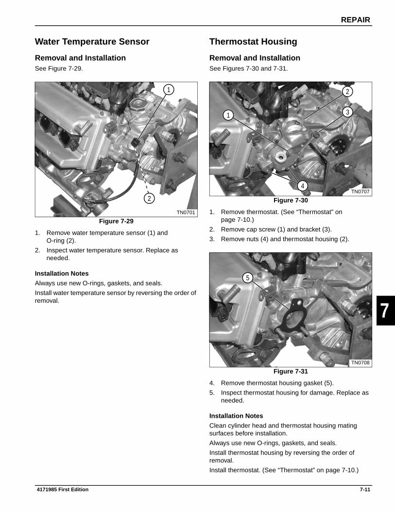
REPAIR
7
Water Temperature Sensor
Removal and InstallationSee Figure 7-29.
Figure 7-29
1. Remove water temperature sensor (1) and O-ring (2).
2. Inspect water temperature sensor. Replace as needed.
Installation Notes
Always use new O-rings, gaskets, and seals.
Install water temperature sensor by reversing the order of removal.
Thermostat Housing
Removal and InstallationSee Figures 7-30 and 7-31.
Figure 7-30
1. Remove thermostat. (See “Thermostat” on page 7-10.)
2. Remove cap screw (1) and bracket (3).
3. Remove nuts (4) and thermostat housing (2).
Figure 7-31
4. Remove thermostat housing gasket (5).
5. Inspect thermostat housing for damage. Replace as needed.
Installation Notes
Clean cylinder head and thermostat housing mating surfaces before installation.
Always use new O-rings, gaskets, and seals.
Install thermostat housing by reversing the order of removal.
Install thermostat. (See “Thermostat” on page 7-10.)
TN0701
1
2TN0707
1
2
3
4
TN0708
5
4171985 First Edition 7-11

REPAIR
7
7.5 Front Cover, Timing Chain, and Tensioner
Cam Angle Sensor
Removal and InstallationSee Figure 7-32.
Figure 7-32
1. Remove cap screw (1).
2. Remove cam angle sensor (2) and O-ring (3).
3. Inspect cam angle sensor. Replace as needed.
Installation Note
Always use new O-rings, gaskets, and seals.
Install cam angle sensor by reversing the order of removal.
Front Cover
RemovalSee Figure 7-33.
1. Remove ignition coils. (See “Ignition Coils” on page 7-8.)
2. Remove spark plugs. (See “Spark Plugs” on page 7-8.)
3. Remove PCV valve. (See “PCV Valve” on page 7-4.)
4. Remove cam cover. (See “Cam Cover” on page 7-17.)
5. Remove crankshaft pulley. (See “Crankshaft Pulley” on page 7-37.)
6. Remove idler pulley. (See “Idler Pulley” on page 7-38.)
7. Remove oil pan. (See “Oil Pan” on page 7-30.)
8. Remove oil pump pickup. (See “Oil Pump Pickup” on page 7-31.)
Figure 7-33
9. Remove idler pulley/alternator bracket (4).
NOTEFront cover is located on cylinder block with dowel pins. Cover must be removed straight away from engine.
10. Remove cap screws (2 and 3) and front cover (1).
TN0709
1
2
3
TN0745
2
1
2
3
2
422
7-12 4171985 First Edition

REPAIR
7
InstallationSee Figures 7-34 and 7-35.
1. Clean cylinder head, cylinder block, and front cover mating surfaces.
Figure 7-34
2. Apply Three Bond™ 1215 sealant to the front cover at shaded areas shown.
IMPORTANTBe sure oil pump inner rotor flats properly engage with those of the crankshaft timing sprocket.
Figure 7-35
3. Align dowel pins, oil pump rotor flats, and crankshaft timing gear. Then install front cover (1).
4. Install cap screws (2 and 3). Tighten to specification.
Front Cover Torque: 97 lb-in. (11 N•m)
5. Install oil pump pickup. (See “Oil Pump Pickup” on page 7-31.)
6. Install oil pan. (See “Oil Pan” on page 7-30.)
7. Install idler pulley/alternator bracket (4).
8. Install idler pulley. (See “Idler Pulley” on page 7-38.)
9. Install crankshaft pulley. (See “Crankshaft Pulley” on page 7-37.)
10. Install cam cover. (See “Cam Cover” on page 7-17.)
11. Install PCV valve. (See “PCV Valve” on page 7-4.)
12. Install spark plugs. (See “Spark Plugs” on page 7-8.)
13. Install ignition coils. (See “Ignition Coils” on page 7-8.)
Required Materials
Three Bond™ 1215 (Suzuki PN 99000-1080-15A) or equivalent
TN0386
TN0745
2
1
2
3
2
422
4171985 First Edition 7-13

REPAIR
7
Tension Adjuster
Removal and InstallationSee Figure 7-36.
Figure 7-36
1. Remove front cover. (See “Front Cover” on page 7-12.)
2. Remove cap screws (1) and tensioner link (2).
3. Remove cap screws (3) and tension adjuster (5).
4. Inspect tension adjuster and tensioner pad (4). Replace as needed.
Installation Note
Install tension adjuster by reversing the order of removal.
Timing Chain
RemovalSee Figures 7-37 and 7-38.
1. Remove front cover. (See “Front Cover” on page 7-12.)
Figure 7-37
NOTESThe crankshaft may need to be rotated several times before cylinder number one reaches top dead center.
All timing index marks must be aligned simultaneously.
2. Turn the crankshaft and satisfy the following conditions to bring number one cylinder to top dead center.
• Blue timing chain links (2) align with slot/arrow (1) on cam timing gears.
• Cam timing gear dots (3) align with index marks (8) on cylinder head.
• Crankshaft timing sprocket keyway (4) faces up and aligns with index mark (7) on cylinder block.
• Yellow timing chain link (6) aligns with crankshaft timing gear slot (5).
TN0549
1
2 3
5
4
TN0502
2
1 1
33
8
7
5
6
4
7-14 4171985 First Edition

REPAIR
7
Figure 7-38
3. Remove cap screws (9) and tensioner link (10).
4. Remove cap screw (16), spacer (17), and tensioner (18).
5. Remove cap screws (11 and 13) and chain guide (12).
6. Slide crankshaft timing sprocket (15) and timing chain (14) off of crankshaft. Remove timing chain from cam gear teeth.
IMPORTANTDo not turn camshafts or crankshaft with timing chain removed.
InspectionSee Figure 7-39.
Figure 7-39
Inspect timing chain (1), chain guide (2), crankshaft timing sprocket (3), and tensioner (4) for wear or damage. Replace as needed.
TN0550
9
1011
12
13
16
17
15
18
14
TN0375
1
2
3
4
4171985 First Edition 7-15

REPAIR
7
InstallationSee Figures 7-40 through 7-42.
IMPORTANTMake sure cylinder number 1 is at top dead center.
Figure 7-40
1. Align blue timing chain links (2) with slot/arrow (1) on cam timing gears.
2. Align cam timing gear dots (3) with index marks (4) on cylinder head.
3. Be sure crankshaft timing sprocket keyway (8) faces up and aligns with index mark (5) on cylinder block.
4. Align yellow timing chain link (7) with crankshaft timing gear slot (6) and slide timing gear onto crankshaft.
NOTICE
Figure 7-41
5. Release tension adjuster (9) manual lock using a rod (11) approximately 0.8 in. (2 mm) in diameter. Depress the lock with the rod and reset the piston (10) as shown.
TN0378
2
1
3
4
58
67
Be sure to re-check timing mark(s) alignment. Improper installation may result in engine damage.
TN0380
1011
9
7-16 4171985 First Edition

REPAIR
7
Figure 7-42
NOTEApply engine oil to timing chain, tensioner, and guide faces.
6. Apply oil to the timing chain guide (15) and secure using cap screws (14 and 16).
7. Install tensioner (19) with spacer (18) and cap screw (17).
8. Install tensioner link (13) using cap screws (12).
9. Install front cover. (See “Front Cover” on page 7-12.)
7.6 Cylinder Head, Cams, and Valve Train
Cam Cover
RemovalSee Figure 7-43.
Figure 7-43
1. Remove ignition coils. (See “Ignition Coils” on page 7-8.)
2. Remove spark plugs. (See “Spark Plugs” on page 7-8.)
3. Remove PCV valve. (See “PCV Valve” on page 7-4.)
4. Remove six cap screws (1) and cam cover (2).
5. Inspect and replace as needed.
TN0550
12
1314
15
16
17
18
19
TN0724
1
1
2
4171985 First Edition 7-17

REPAIR
7
InstallationSee Figures 7-44 and 7-45.
Figure 7-44
1. Clean cam cover and cylinder head gasket surfaces.
2. Install new gasket (1) to cam cover (2).
Figure 7-45
3. Apply Three Bond™ 1215 to locations (3, 4, 5, and 6) as shown.
4. Install cam cover and cap screws. (See “Cam Cover Torque Sequence” on page 7-18.)
Cam Cover Torque Sequence
See Figure 7-46.
Figure 7-46
1. Tighten cap screws (1 through 6) in sequential order as shown. Torque cam cover cap screws at increments of 32 lb-in. (3.6 N•m), until specification is reached.
Cam Cover Cap Screws Torque: 96 lb-in. (11 N•m)
2. Install PCV valve. (See “PCV Valve” on page 7-4.)
3. Install spark plugs. (See “Spark Plugs” on page 7-8.)
4. Install ignition coils. (See “Ignition Coils” on page 7-8.)
Required Materials
Three Bond™ 1215 (Suzuki PN 99000-1080-15A) or equivalent
TN0725
1
2
TN0366
3
6
4
5
TN0554
34
5
61
2
7-18 4171985 First Edition
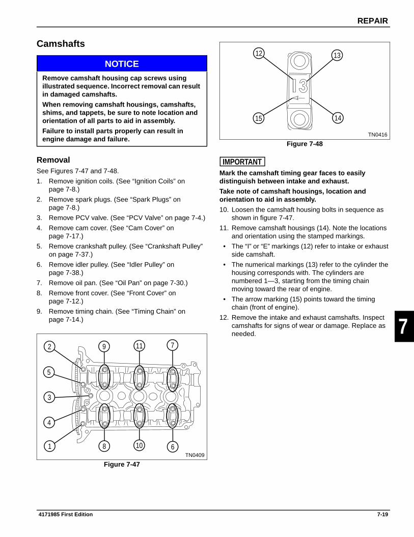
REPAIR
7
Camshafts
NOTICE
RemovalSee Figures 7-47 and 7-48.
1. Remove ignition coils. (See “Ignition Coils” on page 7-8.)
2. Remove spark plugs. (See “Spark Plugs” on page 7-8.)
3. Remove PCV valve. (See “PCV Valve” on page 7-4.)
4. Remove cam cover. (See “Cam Cover” on page 7-17.)
5. Remove crankshaft pulley. (See “Crankshaft Pulley” on page 7-37.)
6. Remove idler pulley. (See “Idler Pulley” on page 7-38.)
7. Remove oil pan. (See “Oil Pan” on page 7-30.)
8. Remove front cover. (See “Front Cover” on page 7-12.)
9. Remove timing chain. (See “Timing Chain” on page 7-14.)
Figure 7-47
Figure 7-48
IMPORTANTMark the camshaft timing gear faces to easily distinguish between intake and exhaust.
Take note of camshaft housings, location and orientation to aid in assembly.
10. Loosen the camshaft housing bolts in sequence as shown in figure 7-47.
11. Remove camshaft housings (14). Note the locations and orientation using the stamped markings.
• The “I” or “E” markings (12) refer to intake or exhaust side camshaft.
• The numerical markings (13) refer to the cylinder the housing corresponds with. The cylinders are numbered 1—3, starting from the timing chain moving toward the rear of engine.
• The arrow marking (15) points toward the timing chain (front of engine).
12. Remove the intake and exhaust camshafts. Inspect camshafts for signs of wear or damage. Replace as needed.
Remove camshaft housing cap screws using illustrated sequence. Incorrect removal can result in damaged camshafts.
When removing camshaft housings, camshafts, shims, and tappets, be sure to note location and orientation of all parts to aid in assembly.
Failure to install parts properly can result in engine damage and failure.
TN0409
1
2
3
4
5
6
7
8
9
10
11
TN0416
13
1415
12
4171985 First Edition 7-19

REPAIR
7
InspectionSee Figures 7-49 through 7-52.
IMPORTANTTappets and shims must be removed before measuring camshaft bearing clearance.
Be sure to note location and shim thickness of each tappet.
Figure 7-49
1. Remove twelve tappets with shims. Be sure to note location and shim thickness of each tappet.
2. Clean the camshaft journals and housings free of all oil.
3. Tear off a piece of Plastigage as long as the full bearing width. (Tear through both the envelope and plastic thread at the same time.) Lay the piece of Plastigage across the full width of the lower bearing shell about 1/4 in. (6.3 mm) off center.
Figure 7-50
IMPORTANTDo not turn camshaft during oil clearance measurement process.
Be sure dowel pins are properly aligned before installing camshaft housings.
4. Install the camshaft housings. Apply engine oil to cap screws and tighten using sequence (1 through 11) at increments of 32 lb-in. (3.6 N•m) until specification is reached. Do not turn camshaft during measurement process.
Cam Housing Cap Screw Torque: 97 lb-in. (11 N•m)
Figure 7-51
5. Remove cap screws and camshaft housings in opposite sequence of installation. The flattened Plastigage (12) will adhere to either the bearing shell or the camshaft.
6. Using the supplied scale (13), take the measurement at the widest point of gauging plastic.
Camshaft Oil Clearance Standard: 0.002—0.003 in. (0.045—0.087 mm)
Camshaft Oil Clearance Limit: 0.004 in. (0.10 mm)
Required Tools and Materials
Plastigage™ Clearance Indicator
Micrometer
Inside Bore Gauge
TN0414
TN0409
11
10
9
8
7
6
5
4
3
2
1
TN0410
12 13
7-20 4171985 First Edition

REPAIR
7
Figure 7-52
7. If the oil clearance exceeds the limit, remove the camshaft and retighten the camshaft housing to specification.
Cam Housing Cap Screw Torque: 97 lb-in. (11 N•m)
8. Using a micrometer and bore gauge, measure the camshaft journal outside diameter (14) and the journal bore diameter (15).
If the measurement is beyond the standard range, either the camshaft or cylinder head must be replaced.
Camshaft Journal Outside Diameter: 0.903—0.904 in. (22.934—22.955 mm)
Camshaft Journal Inside Diameter: 0.905—0.906 in.(23.000—23.021 mm)
Cam Timing Sprocket
See Figure 7-53.
Figure 7-53
Inspect the camshaft timing sprockets (1) for wear and damage. If any abnormal condition is noted, replace the sprocket.
Camshaft Housing Bearing Face
See Figure 7-54.
Figure 7-54
Inspect the camshaft housing bearing face for pitting, melting, and seizure. If any abnormal condition is found, replace the cylinder head.
TN0411
14
15
TN0505
1
TN0408
1
4171985 First Edition 7-21

REPAIR
7
Tappets and Shims
See Figure 7-55.
Figure 7-55
1. Inspect shim (1) and tappet (2) for any signs of wear. If any abnormal condition is found, replace as needed.
2. Measure tappet outside diameter and tappet bore inside diameter. Calculate clearance and compare to specification. Replace as needed.
Tappet and Bore Clearance: 0.0009—0.0024 in. (0.025—0.062 mm)
Tappet and Bore Clearance Limit: 0.003 in. (0.10 mm)
Installation
NOTICE
See Figures 7-56 through 7-59.
Figure 7-56
IMPORTANTBe sure tappets and shims are installed in correct location.
1. Apply engine oil to all surfaces of tappets and shims, and install in proper locations.
Figure 7-57
2. Apply engine oil to camshaft journals, lobes, and timing sprockets. Align timing gear dots (1) with the index marks (2) on the cylinder head.
TN0412
1 2Be sure to install tappets, shims, camshafts, and camshaft housings at proper locations.
Failure to install parts properly can result in engine damage and failure.
TN0414
TN0415
1
2
7-22 4171985 First Edition

REPAIR
7
Figure 7-58
IMPORTANTBe sure camshaft housings are properly located.
Be sure dowel pins are properly aligned before installing camshaft housings.
3. Check that the camshaft housing markings (3, 4, and 6) are located properly.
• The “I” or “E” markings (3) refer to intake or exhaust side camshaft.
• The numerical markings (4) refer to the cylinder the housing corresponds with. The cylinders are numbered 1—3, starting from the timing chain moving toward the rear of engine.
• The arrow marking (6) points toward the timing chain (front of engine).
4. Apply engine oil to cap screws and hand tighten the camshaft housings (5) to the cylinder head.
Figure 7-59
5. Tighten camshaft housings, using sequence(1 through 11) at increments of 32 lb-in. (3.6 N•m) until specification is reached.
Camshaft Housing Torque: 97 lb-in. (11 N•m)
6. Check valve clearance. (See “Valve Clearance Check and Adjustment” on page 5-3.)
7. Install timing chain. (See “Timing Chain” on page 7-14.)
8. Install front cover. (See “Front Cover” on page 7-12.)
9. Install oil pan. (See “Oil Pan” on page 7-30.)
10. Install idler pulley. (See “Idler Pulley” on page 7-38.)
11. Install crankshaft pulley. (See “Crankshaft Pulley” on page 7-37.)
12. Install cam cover. (See “Cam Cover” on page 7-17.)
13. Install PCV valve. (See “PCV Valve” on page 7-4.)
14. Install spark plugs. (See “Spark Plugs” on page 7-8.)
15. Install ignition coils. (See “Ignition Coils” on page 7-8.)
TN0416
4
56
3
TN0409
11
10
9
8
7
6
5
4
3
2
1
4171985 First Edition 7-23
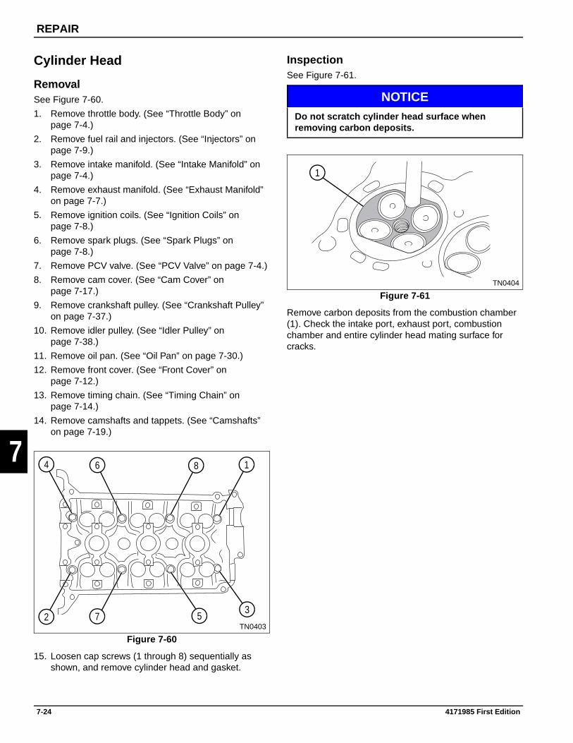
REPAIR
7
Cylinder Head
RemovalSee Figure 7-60.
1. Remove throttle body. (See “Throttle Body” on page 7-4.)
2. Remove fuel rail and injectors. (See “Injectors” on page 7-9.)
3. Remove intake manifold. (See “Intake Manifold” on page 7-4.)
4. Remove exhaust manifold. (See “Exhaust Manifold” on page 7-7.)
5. Remove ignition coils. (See “Ignition Coils” on page 7-8.)
6. Remove spark plugs. (See “Spark Plugs” on page 7-8.)
7. Remove PCV valve. (See “PCV Valve” on page 7-4.)
8. Remove cam cover. (See “Cam Cover” on page 7-17.)
9. Remove crankshaft pulley. (See “Crankshaft Pulley” on page 7-37.)
10. Remove idler pulley. (See “Idler Pulley” on page 7-38.)
11. Remove oil pan. (See “Oil Pan” on page 7-30.)
12. Remove front cover. (See “Front Cover” on page 7-12.)
13. Remove timing chain. (See “Timing Chain” on page 7-14.)
14. Remove camshafts and tappets. (See “Camshafts” on page 7-19.)
Figure 7-60
15. Loosen cap screws (1 through 8) sequentially as shown, and remove cylinder head and gasket.
InspectionSee Figure 7-61.
NOTICE
Figure 7-61
Remove carbon deposits from the combustion chamber (1). Check the intake port, exhaust port, combustion chamber and entire cylinder head mating surface for cracks.
TN0403
1
23
4
5
6
7
8
Do not scratch cylinder head surface when removing carbon deposits.
TN0404
1
7-24 4171985 First Edition

REPAIR
7
Cylinder Block Mating Face Distortion
See Figures 7-62 and 7-63.
IMPORTANTA distorted cylinder head may cause combustion gas to leak through the head gasket, resulting in overheating and reduced power.
Figure 7-62
Figure 7-63
Using a straightedge (2) and a feeler gauge (1), inspect the mating face for distortion. Place the straightedge across bolt hole centers at the locations indicated. Measure any gaps with the feeler gauge. If the measurement exceeds the limit, repair or replace the cylinder head.
Cylinder Block/Head Mating Face Distortion Limit: 0.001 in. (0.03 mm)
Intake and Exhaust Manifold Mating Face Distortion
See Figure 7-64.
Figure 7-64
Using a straightedge (2) and a feeler gauge (1), inspect the manifold mating faces for distortion. Place the straightedge across the mating face, and measure any gaps with the feeler gauge. If the measurement exceeds the limit, repair or replace the cylinder head.
Intake and Exhaust Manifold Mating Face Distortion Limit: 0.000—0.002 in. (0.00—0.05 mm)
TN0405
1 2
TN0406
TN0407
12
4171985 First Edition 7-25

REPAIR
7
InstallationSee Figures 7-65 through 7-67.
IMPORTANTMake sure cylinder head and cylinder block are free of oil and debris.
Make sure cylinder head bolt holes are free of oil, water, or debris.
Figure 7-65
1. Clean cylinder head and cylinder block mating surfaces. Place head gasket on cylinder block with forked end toward the front of the engine (arrow).
2. Install cylinder head using care to align dowel pins.
3. Apply oil to cylinder head cap screw threads and seating faces and install. Do not tighten at this time.
IMPORTANTIf the cylinder head, cylinder block, or the cylinder head cap screw have been replaced, go to step 4.
If installing previously removed parts, go to step 5.
Figure 7-66
4. Torque the cap screws in sequence to 22 lb-ft (30 N•m).
• Set torque wrench to 35 lb-ft (47 N•m) and repeat torque sequence.
• Reverse the torque sequence and loosen all cap screws.
• Re-torque cap screws in sequence to 35 lb-ft (47 N•m).
• Torque cap screws (1 through 8) in sequence to final specification.
Cylinder Head Cap Screw Torque: 43.5 lb-ft (59 N•m)
Figure 7-67
5. Tighten cap screws (1 through 8) in sequence, to specification.
Cylinder Head Cap Screw Torque: 43.5 lb-ft (59 N•m)
TN0413
TN0403
1
23
4
5
6
7
8
TN0403
1
23
4
5
6
7
8
7-26 4171985 First Edition

REPAIR
7
Valves
DisassemblySee Figure 7-68.
Figure 7-68
1. Remove shims (1) and tappets (2).
2. Using a valve spring compressor, remove retainer locks (8).
3. Release valve spring compressor and removevalve (5).
4. Remove valve spring retainer (7), valve spring (3), valve seal (4), and valve spring seat (6).
5. Inspect all parts for wear or damage. (See “Inspection” on page 7-28.)
Required Tools
Valve Spring Compressor
TN0492
6
8
1
5
3
4
2
7
4171985 First Edition 7-27
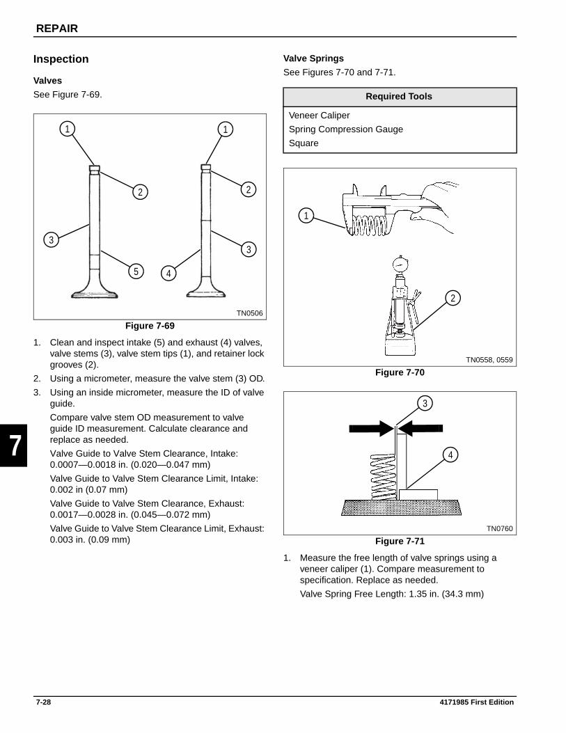
REPAIR
7
Inspection
Valves
See Figure 7-69.
Figure 7-69
1. Clean and inspect intake (5) and exhaust (4) valves, valve stems (3), valve stem tips (1), and retainer lock grooves (2).
2. Using a micrometer, measure the valve stem (3) OD.
3. Using an inside micrometer, measure the ID of valve guide.
Compare valve stem OD measurement to valve guide ID measurement. Calculate clearance and replace as needed.
Valve Guide to Valve Stem Clearance, Intake: 0.0007—0.0018 in. (0.020—0.047 mm)
Valve Guide to Valve Stem Clearance Limit, Intake: 0.002 in (0.07 mm)
Valve Guide to Valve Stem Clearance, Exhaust: 0.0017—0.0028 in. (0.045—0.072 mm)
Valve Guide to Valve Stem Clearance Limit, Exhaust: 0.003 in. (0.09 mm)
Valve Springs
See Figures 7-70 and 7-71.
Figure 7-70
Figure 7-71
1. Measure the free length of valve springs using a veneer caliper (1). Compare measurement to specification. Replace as needed.
Valve Spring Free Length: 1.35 in. (34.3 mm)
TN0506
1
33
1
22
45
Required Tools
Veneer Caliper
Spring Compression Gauge
Square
TN0558, 0559
1
2
TN0760
3
4
7-28 4171985 First Edition

REPAIR
7
2. Using a spring compression gauge (2), compress the valve spring to 1.17 in. (29.9 mm). Compare the tension reading to specification and replace as needed.
Pound Force at 1.17 in. (29.9 mm) Height:
Valve Spring Tension Standard: 22—26 lb-ft (100—116 N•m)
Valve Spring Tension Limit: 20 lb-ft (88 N•m)
3. Using a square (4), check valve spring right angle. Use a feeler gauge to measure distance (3). Compare measurement to specification. Replace as needed.
Valve Spring Right Angle Range: 0.000—0.059 in.(0.00—1.5 mm)
Installation Notes
Always use new O-rings, gaskets, and seals.
Apply clean engine oil to tappet and valve stem contact surfaces.
Install valve assemblies with new valve seals by reversing the order of removal.
Check valve clearance. (See “Valve Clearance Check and Adjustment” on page 5-3.)
4171985 First Edition 7-29

REPAIR
7
7.7 Lubrication System
Dipstick Tube
Removal and InstallationSee Figure 7-72.
Figure 7-72
1. Remove nut (1).
2. Remove dipstick tube (2) and O-ring (3).
3. Inspect dipstick tube and O-ring. Replace as needed.
Installation Notes
Always use new O-rings, gaskets, and seals.
Install dipstick tube by reversing the order of removal.
Oil Pan
RemovalSee Figure 7-73.
Figure 7-73
1. Drain engine oil. (See “Change Engine Oil” on page 3-2.)
2. Remove twelve cap screws (2), three nuts (1), and oil pan (3).
3. Inspect oil pan. Replace as needed.
TN0713
1
2
3
TN0741
1 1
1
2
2
2
2
3
7-30 4171985 First Edition
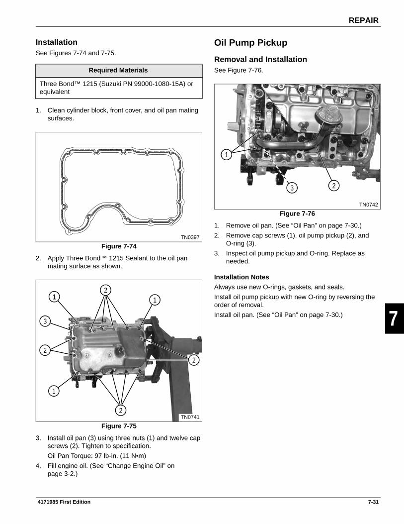
REPAIR
7
InstallationSee Figures 7-74 and 7-75.
1. Clean cylinder block, front cover, and oil pan mating surfaces.
Figure 7-74
2. Apply Three Bond™ 1215 Sealant to the oil pan mating surface as shown.
Figure 7-75
3. Install oil pan (3) using three nuts (1) and twelve cap screws (2). Tighten to specification.
Oil Pan Torque: 97 lb-in. (11 N•m)
4. Fill engine oil. (See “Change Engine Oil” on page 3-2.)
Oil Pump Pickup
Removal and InstallationSee Figure 7-76.
Figure 7-76
1. Remove oil pan. (See “Oil Pan” on page 7-30.)
2. Remove cap screws (1), oil pump pickup (2), and O-ring (3).
3. Inspect oil pump pickup and O-ring. Replace as needed.
Installation Notes
Always use new O-rings, gaskets, and seals.
Install oil pump pickup with new O-ring by reversing the order of removal.
Install oil pan. (See “Oil Pan” on page 7-30.)
Required Materials
Three Bond™ 1215 (Suzuki PN 99000-1080-15A) or equivalent
TN0397
TN0741
1 1
1
2
2
2
2
3
TN0742
1
23
4171985 First Edition 7-31

REPAIR
7
Crankshaft Baffle
Removal and InstallationSee Figure 7-77.
1. Remove oil pan. (See “Oil Pan” on page 7-30.)
2. Remove oil pump pickup. (See “Oil Pump Pickup” on page 7-31.)
Figure 7-77
NOTECap screws (1) require the use of a 12-point 8 mm socket.
3. Remove cap screws (1 and 2) and crankshaft baffle (3).
Installation Notes
Install crankshaft baffle by reversing the order of removal.
Install oil pump pickup. (See “Oil Pump Pickup” on page 7-31.)
Install oil pan. (See “Oil Pan” on page 7-30.)
Oil Pressure Sending Unit
Removal and InstallationSee Figure 7-78.
Figure 7-78
1. Remove oil pressure sending unit (1).
2. Inspect oil pressure sending unit. Replace as needed.
Installation Notes
Apply thread sealant to the oil pressure sending unit before installation.
Install oil pressure sending unit by reversing the order of removal.
Required Tools
12-Point 8 mm Socket
TN0743
32
1
TN0715
1
7-32 4171985 First Edition
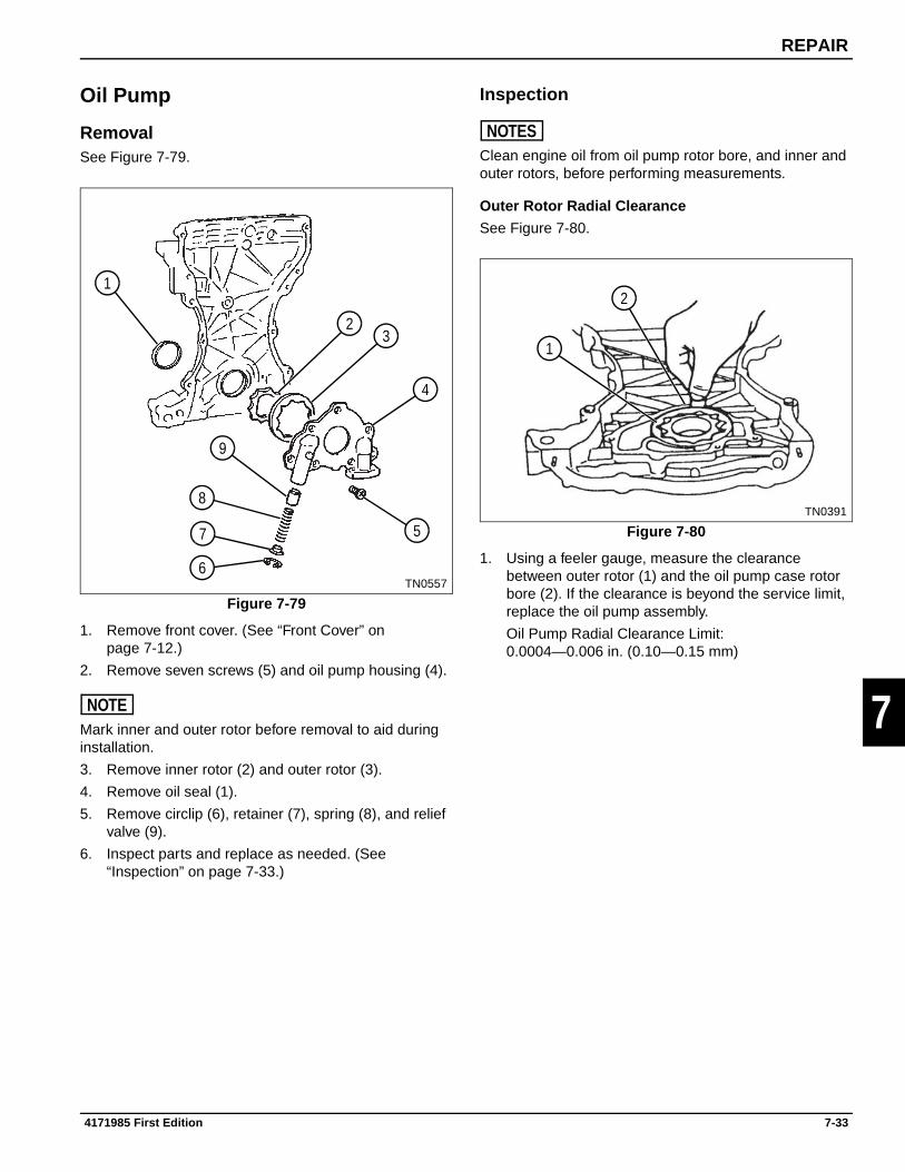
REPAIR
7
Oil Pump
RemovalSee Figure 7-79.
Figure 7-79
1. Remove front cover. (See “Front Cover” on page 7-12.)
2. Remove seven screws (5) and oil pump housing (4).
NOTEMark inner and outer rotor before removal to aid during installation.
3. Remove inner rotor (2) and outer rotor (3).
4. Remove oil seal (1).
5. Remove circlip (6), retainer (7), spring (8), and relief valve (9).
6. Inspect parts and replace as needed. (See “Inspection” on page 7-33.)
Inspection
NOTESClean engine oil from oil pump rotor bore, and inner and outer rotors, before performing measurements.
Outer Rotor Radial Clearance
See Figure 7-80.
Figure 7-80
1. Using a feeler gauge, measure the clearance between outer rotor (1) and the oil pump case rotor bore (2). If the clearance is beyond the service limit, replace the oil pump assembly.
Oil Pump Radial Clearance Limit:0.0004—0.006 in. (0.10—0.15 mm)
TN0557
1
23
4
5
6
9
8
7
TN0391
1
2
4171985 First Edition 7-33

REPAIR
7
Outer Rotor Side Clearance
See Figure 7-81.
Figure 7-81
1. Place a straightedge (1) across the oil pump rotor bore. Use a feeler gauge (2) to measure the clearance between the straightedge and the outer rotor side surface. If measurement is beyond service limit, replace the oil pump assembly.
Oil Pump Outer Rotor Side Clearance Limit:0.003—0.005 in. (0.076—0.127 mm)
Inner Rotor and Pump Case Clearance
See Figure 7-82.
Figure 7-82
1. Using a micrometer, measure the outside diameter of the inner rotor shoulder (1).
2. Measure the inside diameter of the oil pump bore hole (2). If measurements are not within service limit, replace oil pump assembly.
Inner Rotor and Pump Case Clearance: 0.001—0.003 in. (0.025—0.076 mm)
TN0392
1
2
TN0394
1
2
7-34 4171985 First Edition

REPAIR
7
Relief Valve Spring
See Figure 7-83.
Figure 7-83
1. Use a veneer caliper to measure the free length of relief valve spring (1). If relief valve spring measures less than specification, replace the spring.
Oil Pump Relief Valve Spring Free Length: 2.063 in. (52.40 mm)
2. Using a spring compression gauge (2), compress relief valve spring to specification and record the force reading. If force reading is less than specification, replace the spring.
Oil Pump Relief Valve Spring Tension at 1.516 in.(38.5 mm) of Length: 17.3 lb-ft (23.45 N•m)
Required Tools
Veneer Caliper
Spring Compression Gauge
TN0558, 0559
1
2
4171985 First Edition 7-35

REPAIR
7
InstallationSee Figures 7-84 and 7-85.
Figure 7-84
1. Using bushing, bearing, and seal driver (1), install new oil seal (2) into front cover (3).
Figure 7-85
NOTEInstall inner and outer rotor as previously marked.
2. Install relief valve (11), spring (10), retainer (9), and circlip (8).
3. Install inner rotor (4) and outer rotor (5).
4. Install oil pump housing (6) using screws (7). Tighten to specification.
Oil Pump Housing Torque: 60 lb-in. (6.78 N•m)
Required Tools
Bushing, Bearing and Seal Driver (Suzuki PN 09913-75520) or equivalent
TN0561
12
3
TN0557
45
6
7
8
11
10
9
7-36 4171985 First Edition

REPAIR
7
7.8 Cylinder Block and Lower Crankcase
Knock Sensor
Removal and InstallationSee Figure 7-86.
Figure 7-86
1. Use a small screwdriver to depress internal tab (2) and release electrical connector (3) from bracket (1).
2. Remove knock sensor (4) from cylinder block.
3. Inspect and replace as needed.
Installation Notes
Install knock sensor by reversing the order of removal.
Tighten knock sensor to specification.
Knock Sensor Torque: 203 lb-in. (23 N•m)
Crankshaft Pulley
Removal and InstallationSee Figure 7-87.
Figure 7-87
1. Remove cap screw (1) and crankshaft pulley (2).
2. Inspect and replace as needed.
Installation Notes
Install crankshaft pulley by reversing the order of removal.
Tighten crankshaft pulley cap screw to specification.
Crankshaft Pulley Cap Screw: 72 lb-ft (98 N•m)
TN0718
12 3
4
TN0721
2
1
4171985 First Edition 7-37

REPAIR
7
Idler Pulley
Removal and InstallationSee Figures 7-88 and 7-89.
Figure 7-88
1. Remove cap screws (1).
Figure 7-89
2. Remove idler pulley (3) and spacer (2).
3. Inspect and replace as needed.
Installation Note
Install idler pulley by reversing the order of removal.
Connecting Rods and Pistons
RemovalSee Figure 7-90.
1. Remove cylinder head. (See “Cylinder Head” on page 7-24.)
2. Remove oil pan. (See “Oil Pan” on page 7-30.)
3. Remove oil pump pickup. (See “Oil Pump Pickup” on page 7-31.)
4. Remove crankshaft baffle. (See “Crankshaft Baffle” on page 7-32.)
Figure 7-90
IMPORTANTNote the placement and orientation of connecting rods and caps prior to removal.
5. The connecting rods and caps are stamped “2N” (3) on the intake manifold side of the engine. Mark the opposite (exhaust) side of connecting rods and caps 1 through 3, starting at the timing chain (front of engine) moving toward the back.
6. Remove nuts (1) and cap (2).
NOTICE
7. Place rubber hose over connecting rod bolts and slide connecting rod and piston out the top of the cylinder block.
TN0721
1
TN0722
32
Prevent cylinder bore damage. Place rubber hose over connecting rod bolts before removing from cylinder.
Do not drop piston and rod assembly. When the piston rings are free of the cylinder bore, the assembly will move freely.
TN0752
21
3
7-38 4171985 First Edition

REPAIR
7
DisassemblySee Figures 7-91 and 7-92.
Figure 7-91
1. Label pistons to correspond with previously labeled connecting rods.
2. Remove circlips (1), piston pin (6), and connecting rod (5).
IMPORTANTBe sure to note location and orientation of piston rings to aid in assembly.
NOTICE
3. Using a piston ring expander, remove piston rings (2, 3, and 4). Be sure to note location and orientation of each ring.
Figure 7-92
4. Remove bearings (8) from connecting rod (7) and cap (9).
5. Inspect all parts for wear or damage. Replace as needed.
Inspection
Connecting Rods
1. Inspect connecting rods for cracks, wear, or damage. Replace as needed.
2. Measure connecting rod small end ID. Compare measurement to specification and piston pin OD specification. Repair or replace as needed.
Connecting Rod Small End ID: 0.7087—0.7090 in. (18.003—18.011 mm)
Piston Pin OD: 0.7084—0.7086 in. (17.995—18.000 mm)
3. Measure connecting rod large end ID. Compare measurement to specification and crankshaft connecting rod journal OD specification. Calculate or measure oil clearance and compare to specification. Repair or replace as needed.
Connecting Rod Large End ID: 1.6141—1.6148 in. (41.000—41.018 mm)
Crankshaft Connecting Rod Journal OD: 1.495—1.496 in. (37.982—38.000 mm)
Crankshaft/Connecting Rod Oil Clearance: 0.0007—0.0015 in. (0.020—0.040 mm)
Crankshaft/Connecting Rod Oil Clearance Limit: 0.002 in. (0.065 mm)
Required Tools
Piston Ring Expander
Do not expand piston rings any further than necessary to remove. Piston rings can be damaged if expanded too far.
TN0753
1
6
5
2
3
4 TN0499
7 8
9
4171985 First Edition 7-39

REPAIR
7
Piston, Piston Pin, and Piston Rings
1. Inspect piston, piston pin, and piston rings for cracks, wear, or damage. Replace as needed.
2. Measure piston OD. Compare to specification and cylinder bore ID. Replace as needed.
Piston OD: 2.675—2.676 in. (67.970—67.990 mm)
Cylinder Bore ID: 2.6771—2.6779 in. (68.000—68.020 mm)
3. Measure piston pin OD. Compare measurement to specification and connecting rod small end ID. Replace as needed.
Piston Pin OD: 0.7084—0.7086 in. (17.995—18.000 mm)
Connecting Rod Small End ID: 0.7087—0.7090 in. (18.003—18.011 mm)
4. Measure piston rings end gap. Compare to specifications. Replace as needed.
Top Compression Ring End Gap: 0.0047—0.0106 in. (0.12—0.27 mm)
Top Compression Ring End Gap Limit: 0.027 in. (0.7 mm)
Second Compression Ring End Gap: 0.0137—0.0196 in. (0.35—0.50 mm)
Second Compression Ring End Gap Limit: 0.039 in. (1.0 mm)
Oil Control Ring End Gap: 0.0039—0.0157 in. (0.10—0.40 mm)
Oil Control Ring End Gap Limit: 0.047 in. (1.2 mm)
Assembly
NOTICE
See Figures 7-93 through 7-97.
Figure 7-93
NOTEBe sure to align bearing tangs (4) with recessed grooves in the connecting rod and cap.
1. Align bearing tangs (4) with recessed grooves in connecting rod (2) and cap (1) and install bearings (3).
Prevent engine failure. Always clean parts of dirt and debris. Coat all bearings and contact surfaces with clean oil.
Required Tools
Piston Ring Expander, Piston Ring Compressor
TN0754
1 2
33 4 4
7-40 4171985 First Edition

REPAIR
7
Figure 7-94
Figure 7-95
IMPORTANTInstall all piston rings with markings facing the top of the piston. Be sure to position the piston ring gaps as shown.
2. Using a piston ring expander, install the bottom oil control ring (7). Align the expander ring gap (8) with the intake side of piston. Align the control ring gaps (9 and 12) as shown.
3. Using a piston ring expander, install the second piston ring (6) with markings facing up, and the undercut facing down. Position the ring gap (10) as shown.
4. Using a piston ring expander, install the first ring (5) with markings facing the top of the piston. Position the ring gap (11) as shown.
Figure 7-96
NOTEApply clean oil to piston pin, connecting rod, and piston contact surfaces before assembly.
5. Install connecting rod (15), piston pin (14), and circlips (13) to piston (16).
NOTICE
6. Cover connecting rod bolts with rubber hose and apply clean oil to connecting rod bearing.
NOTEConfirm the proper position of ring gaps before installing piston ring compressor.
7. Using a piston ring compressor, install the piston and connecting rod as an assembly. Be sure the arrow on face of piston faces the timing chain (front of engine).
Be sure the stamping “2N” on connecting rods and caps face the intake side of the engine, along with the valve reliefs in the face of the piston.
Be sure the piston and connecting rod are installed in the correct cylinder, as previously numbered.
8. Coat the crankshaft rod journal with clean engine oil and carefully engage the connecting rod.
TN0529
6
5
7
9
8
12
1011 Prevent cylinder bore damage. Place rubber hose over connecting rod bolts before installing.
TN0753
15
1416
13
4171985 First Edition 7-41

REPAIR
7
Figure 7-97
NOTEApply clean oil to the connecting rod cap bearing and crankshaft journal.
9. Install connecting rod cap (17) and nuts (18). Tighten to specification.
Connecting Rod Torque: 24 lb-ft (33 N•m)
10. Install crankshaft baffle. (See “Crankshaft Baffle” on page 7-32.)
11. Install oil pump pickup. (See “Oil Pump Pickup” on page 7-31.)
12. Install oil pan. (See “Oil Pan” on page 7-30.)
13. Install cylinder head. (See “Cylinder Head” on page 7-24.)
Lower Crankcase, Cylinder Block, and Crankshaft
DisassemblySee Figures 7-98 through 7-101.
1. Remove cylinder head. (See “Cylinder Head” on page 7-24.)
2. Remove oil pan. (See “Oil Pan” on page 7-30.)
3. Remove oil pump pickup. (See “Oil Pump Pickup” on page 7-31.)
4. Remove crankshaft baffle. (See “Crankshaft Baffle” on page 7-32.)
Figure 7-98
5. Using a 12-point 8 mm socket, remove six screws and washers (1).
6. Using a 12-point 10 mm socket, remove eight screws and washers (2).
NOTEThe lower crankcase is located using four dowel pins and is sealed to the cylinder block using Three Bond ™ 1215 sealant. The lower crankcase must be lifted off square.
7. Use a soft face mallet to loosen lower crankcase (3) from cylinder block. Remove lower crankcase from cylinder block. Be sure to lift lower crankcase off square.
TN0752
17 18
Required Tools
8 and 10 mm 12-point sockets
TN0755
1 12
2
123
2
7-42 4171985 First Edition

REPAIR
7
Figure 7-99
8. Remove rear main seal (4) and crankshaft (5).
Figure 7-100
9. Remove crankshaft main bearings (6) and thrust bearings (7).
Figure 7-101
10. Remove other half of crankshaft main bearings (9) from lower crankcase (8).
TN0756
4 5
TN0757
6 6
7 7
TN0758
9
9
8
4171985 First Edition 7-43
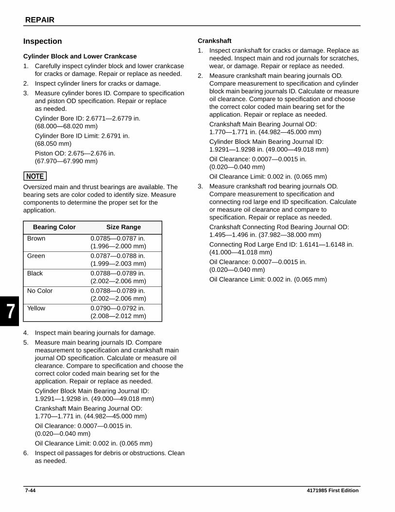
REPAIR
7
Inspection
Cylinder Block and Lower Crankcase
1. Carefully inspect cylinder block and lower crankcase for cracks or damage. Repair or replace as needed.
2. Inspect cylinder liners for cracks or damage.
3. Measure cylinder bores ID. Compare to specification and piston OD specification. Repair or replace as needed.
Cylinder Bore ID: 2.6771—2.6779 in. (68.000—68.020 mm)
Cylinder Bore ID Limit: 2.6791 in. (68.050 mm)
Piston OD: 2.675—2.676 in. (67.970—67.990 mm)
NOTEOversized main and thrust bearings are available. The bearing sets are color coded to identify size. Measure components to determine the proper set for the application.
4. Inspect main bearing journals for damage.
5. Measure main bearing journals ID. Compare measurement to specification and crankshaft main journal OD specification. Calculate or measure oil clearance. Compare to specification and choose the correct color coded main bearing set for the application. Repair or replace as needed.
Cylinder Block Main Bearing Journal ID: 1.9291—1.9298 in. (49.000—49.018 mm)
Crankshaft Main Bearing Journal OD: 1.770—1.771 in. (44.982—45.000 mm)
Oil Clearance: 0.0007—0.0015 in. (0.020—0.040 mm)
Oil Clearance Limit: 0.002 in. (0.065 mm)
6. Inspect oil passages for debris or obstructions. Clean as needed.
Crankshaft
1. Inspect crankshaft for cracks or damage. Replace as needed. Inspect main and rod journals for scratches, wear, or damage. Repair or replace as needed.
2. Measure crankshaft main bearing journals OD. Compare measurement to specification and cylinder block main bearing journals ID. Calculate or measure oil clearance. Compare to specification and choose the correct color coded main bearing set for the application. Repair or replace as needed.
Crankshaft Main Bearing Journal OD: 1.770—1.771 in. (44.982—45.000 mm)
Cylinder Block Main Bearing Journal ID: 1.9291—1.9298 in. (49.000—49.018 mm)
Oil Clearance: 0.0007—0.0015 in. (0.020—0.040 mm)
Oil Clearance Limit: 0.002 in. (0.065 mm)
3. Measure crankshaft rod bearing journals OD. Compare measurement to specification and connecting rod large end ID specification. Calculate or measure oil clearance and compare to specification. Repair or replace as needed.
Crankshaft Connecting Rod Bearing Journal OD: 1.495—1.496 in. (37.982—38.000 mm)
Connecting Rod Large End ID: 1.6141—1.6148 in. (41.000—41.018 mm)
Oil Clearance: 0.0007—0.0015 in. (0.020—0.040 mm)
Oil Clearance Limit: 0.002 in. (0.065 mm)
Bearing Color Size Range
Brown 0.0785—0.0787 in.(1.996—2.000 mm)
Green 0.0787—0.0788 in.(1.999—2.003 mm)
Black 0.0788—0.0789 in.(2.002—2.006 mm)
No Color 0.0788—0.0789 in.(2.002—2.006 mm)
Yellow 0.0790—0.0792 in.(2.008—2.012 mm)
7-44 4171985 First Edition

REPAIR
7
AssemblySee Figures 7-102 through 7-107.
NOTICE
Figure 7-102
NOTEThoroughly clean lower crankcase/cylinder block mating surface.
1. Thoroughly clean main bearing bores and install main bearings (2) into lower crankcase (1). Be sure to align bearing tangs (3) with recess in main bearing bores.
2. Apply a liberal amount of clean engine oil to main bearing faces.
Figure 7-103
3. Thoroughly clean cylinder block main bearing bores, and install main bearings (4). Be sure to align bearing tangs (5) with recess in main bearing bores.
4. Install thrust bearings (6) with a small amount of petroleum jelly to keep them in place.
5. Apply a liberal amount of clean engine oil to main and thrust bearing faces.
Figure 7-104
NOTEThoroughly clean cylinder block/lower crankcase mating surface.
Thoroughly clean crankshaft journals before installation.
6. Apply a liberal amount of clean engine oil to crankshaft main journals (8) and connecting rod journals (10).
7. Install crankshaft (9) into cylinder block (11).
8. Install four dowel pins (7).
Required Tools and Materials
8 and 10 mm 12-point sockets
Three Bond™ 1215 (Suzuki PN 99000-1080-15A) or equivalent
Bushing, Bearing, and Seal Driver Tool
Prevent premature engine failure:
• Thoroughly clean all parts before assembly.
• Clean all gasket surfaces.
• Clean all sealant bonded mating surfaces.
• Tap cylinder block and lower crankcase threaded holes. Use compressed air to clean out debris, dirt, fluids, and dried sealant fragments.
• Clean debris from threads of all fasteners.
TN0758
2
1
3
2
3
TN0757
4 4
6 6
5
5
TN0756
8
10
9
11
7
4171985 First Edition 7-45

REPAIR
7
9. Apply Three Bond™ 1215 to the lower crankcase mating surface.
Figure 7-105: Torque Sequence M10 Cap Screws
NOTEApply a liberal amount of clean engine oil to lower crankcase main bearings and crankshaft main bearing journals.
10. Install lower crankcase to cylinder block.
NOTEApply engine oil to the threads of M10 cap screws and washers and install as shown.
11. Using a 12-point 10 mm socket, tighten eight screws and washers sequentially (12 through 19) to 30 lb-ft(40 N•m).
Loosen all cap screws in the reverse order.
Tighten eight screws and washers sequentially (12 through 19) to 30 lb-ft (40 N•m).
Torque cap screws sequentially (12 through 19) to final specification.
Lower Crankcase (M10) Cap Screw Torque: 42 lb-ft (57 N•m)
Figure 7-106: Torque Sequence M8 Cap Screws
IMPORTANTThe remaining two M8 main bearing cap screws are installed with the crankshaft baffle. (See “Crankshaft Baffle” on page 7-32.)
12. Using a 12-point 8 mm socket, tighten six screws and washers sequentially (20 through 25) to specification.
Lower Crankcase (M8) Cap Screw Torque: 212 lb-in. (24 N•m)
TN0755
13
12
14
15
16
17
18
19
TN0755
21
20
22
23
2425
7-46 4171985 First Edition

REPAIR
7
Figure 7-107
13. Apply Three Bond™ 1215 to cylinder block/lower crankcase joints (26).
NOTEApply clean engine oil to rear main seal inner diameter and crankshaft stub seal surface.
14. Using a bushing, bearing, and seal driver tool, install new rear main seal (27).
15. Rotate crankshaft and check for any abnormal resistance.
16. Install crankshaft baffle. (See “Crankshaft Baffle” on page 7-32.)
17. Install oil pump pickup. (See “Oil Pump Pickup” on page 7-31.)
18. Install oil pan. (See “Oil Pan” on page 7-30.)
19. Install cylinder head. (See “Cylinder Head” on page 7-24.)
TN0759
26 26
27
4171985 First Edition 7-47

REPAIR
7
Page Intentionally Blank
7-48 4171985 First Edition

Chapter 8
Tools and Materials
8
Special Tools . . . . . . . . . . . . . . . . . . . . . . . . . . . . . . . . . . . . . . . . . . . . . . . . . . . . . . . . . . . . . . . . . 8-1
Required Materials . . . . . . . . . . . . . . . . . . . . . . . . . . . . . . . . . . . . . . . . . . . . . . . . . . . . . . . . . . . . . 8-2
4171985 First Edition 8-1

TOOLS AND MATERIALS
8
Special ToolsSee Figures 8-1 through 8-9.
The following tools or suitable equivalents must be used to perform some procedures within this manual. Always use the correct tool for the job.
Figure 8-1: Oil Filter Wrench
Figure 8-2: Oil Pressure Gauge
Figure 8-3: Oil Pressure Gauge Attachment
Figure 8-4: Compression Gauge Set
Figure 8-5: Compression Gauge Hose
Description Suzuki Part Number
Oil Filter Wrench 09915-47341
Oil Pressure Gauge 09915-77311
Oil Pressure Gauge Attachment
09915-78211
Compression Gauge Set
09915-64512
Compression Gauge Hose
09915-64530
Compression Gauge Hose Attachment B
09915-64550
Vacuum Gauge 09915-67311
Tappet Holder (Jacobsen PN) 4139726
Regulator 09918-18111
8-2 4171985 First Edition

TOOLS AND MATERIALS
8
Figure 8-6: Compression Gauge Hose Attachment B
Figure 8-7: Vacuum Gauge
Figure 8-8: Tappet Holder
Figure 8-9: Bearing Installer
Required MaterialsThe following materials or suitable equivalents must be used to perform some procedures within this manual. Always use the right supplies for the job.
Description Part Number
Plastigage Oil Clearance Kit —
Three Bond™ 1215 Sealant Suzuki PN 99000-1080-15A
Anti-Seize Compound —
4171985 First Edition 8-3

TOOLS AND MATERIALS
8
Page Intentionally Blank
8-4 4171985 First Edition

INDEX
XX
IIA
Air Intake and Exhaust SystemsRemoval and Installation . . . . . . . . . . . . . . . . 7-3Repair . . . . . . . . . . . . . . . . . . . . . . . . . . . . . . 7-3Specifications . . . . . . . . . . . . . . . . . . . . . . . . . 2-5Tests and Adjustments . . . . . . . . . . . . . . . . . 5-2
Air Intake, Fuel, and ExhaustTheory of Operation . . . . . . . . . . . . . . . . . . . . 4-4
Air Tools, Safety . . . . . . . . . . . . . . . . . . . . . . . . . 1-4
C
Cam Angle SensorRemoval and Installation . . . . . . . . . . . . . . . 7-12Repair . . . . . . . . . . . . . . . . . . . . . . . . . . . . . 7-12
Cam CoverInstallation . . . . . . . . . . . . . . . . . . . . . . . . . . 7-17Removal . . . . . . . . . . . . . . . . . . . . . . . . . . . . 7-17Repair . . . . . . . . . . . . . . . . . . . . . . . . . . . . . 7-17Torque Sequence . . . . . . . . . . . . . . . . . . . . 7-18
Cam Timing SprocketInspection . . . . . . . . . . . . . . . . . . . . . . . . . . . 7-20
CamshaftTheory of Operation . . . . . . . . . . . . . . . . . . . 4-10
Camshaft Housing Bearing FaceInspection . . . . . . . . . . . . . . . . . . . . . . . . . . . 7-20
CamshaftsCam Housing Bolt Removal Sequence . . . . 7-21Camshaft Housing Bolt Removal Sequence 7-18Inspection . . . . . . . . . . . . . . . . . . . . . . . . . . . 7-19Installation . . . . . . . . . . . . . . . . . . . . . . . . . . 7-21Removal . . . . . . . . . . . . . . . . . . . . . . . . . . . . 7-18Repair . . . . . . . . . . . . . . . . . . . . . . . . . . . . . 7-18
Chemical Products, Safe Handling . . . . . . . . . . 1-5
Compressed Air, Safety . . . . . . . . . . . . . . . . . . . 1-4
Connecting RodTheory of Operation . . . . . . . . . . . . . . . . . . . 4-14
Connecting RodsInspection . . . . . . . . . . . . . . . . . . . . . . . . . . . 7-35
Connecting Rods and PistonsAssembly . . . . . . . . . . . . . . . . . . . . . . . . . . . 7-35Disassembly . . . . . . . . . . . . . . . . . . . . . . . . . 7-34Inspection . . . . . . . . . . . . . . . . . . . . . . . . . . . 7-35Removal . . . . . . . . . . . . . . . . . . . . . . . . . . . . 7-34Repair . . . . . . . . . . . . . . . . . . . . . . . . . . . . . 7-34
Cooling SystemRepair . . . . . . . . . . . . . . . . . . . . . . . . . . . . . 7-10Specifications . . . . . . . . . . . . . . . . . . . . . . . . 2-5Tests and Adjustments . . . . . . . . . . . . . . . . . 5-3Theory of Operation . . . . . . . . . . . . . . . . . . . 4-5
CrankshaftInspection . . . . . . . . . . . . . . . . . . . . . . . . . . 7-39Theory of Operation . . . . . . . . . . . . . . . . . . 4-13
Crankshaft BaffleRemoval and Installation . . . . . . . . . . . . . . 7-29Repair . . . . . . . . . . . . . . . . . . . . . . . . . . . . . 7-29
Crankshaft PulleyRemoval and Installation . . . . . . . . . . . . . . 7-33Repair . . . . . . . . . . . . . . . . . . . . . . . . . . . . . 7-33
Cylinder Block and Lower CrankcaseInspection . . . . . . . . . . . . . . . . . . . . . . . . . . 7-38Repair . . . . . . . . . . . . . . . . . . . . . . . . . . . . . 7-33Theory of Operation . . . . . . . . . . . . . . . . . . 4-13
Cylinder Block, Lower Crankcase, and CrankshaftSpecifications . . . . . . . . . . . . . . . . . . . . . . . . 2-9
Cylinder CompressionTest . . . . . . . . . . . . . . . . . . . . . . . . . . . . . . . . 5-6
Cylinder HeadHead Bolt Removal Sequence . . . . . . . . . . 7-23Inspection . . . . . . . . . . . . . . . . . . . . . . . . . . 7-23Installation . . . . . . . . . . . . . . . . . . . . . . . . . . 7-24Removal . . . . . . . . . . . . . . . . . . . . . . . . . . . 7-23Repair . . . . . . . . . . . . . . . . . . . . . . . . . . . . . 7-23Torque Sequence . . . . . . . . . . . . . . . . . . . . 7-24
Cylinder Head and Valve TrainTheory of Operation . . . . . . . . . . . . . . . . . . . 4-9
Cylinder Head, Cams, and Valve TrainRepair . . . . . . . . . . . . . . . . . . . . . . . . . . . . . 7-17Specifications . . . . . . . . . . . . . . . . . . . . . . . . 2-6Tests and Adjustments . . . . . . . . . . . . . . . . . 5-3
D
DiagnosticTroubleshooting . . . . . . . . . . . . . . . . . . . . . . 6-2
Dipstick TubeRemoval and Installation . . . . . . . . . . . . . . 7-28Repair . . . . . . . . . . . . . . . . . . . . . . . . . . . . . 7-28
4171985 First Edition IX-1

INDEX
IX
E
ElectricalSpecifications . . . . . . . . . . . . . . . . . . . . . . . . . 2-5
Electrical Components, Safety . . . . . . . . . . . . . 1-5
Electrical SystemRemoval and Installation . . . . . . . . . . . . . . . . 7-8Repair . . . . . . . . . . . . . . . . . . . . . . . . . . . . . . . 7-8
EngineComponent Locations . . . . . . . . . . . . . . . . . . 2-3
Engine OilChange . . . . . . . . . . . . . . . . . . . . . . . . . . . . . . 3-2Check Level . . . . . . . . . . . . . . . . . . . . . . . . . . 3-2
Exhaust ManifoldInspection . . . . . . . . . . . . . . . . . . . . . . . . . . . . 7-6Installation . . . . . . . . . . . . . . . . . . . . . . . . . . . 7-7Removal . . . . . . . . . . . . . . . . . . . . . . . . . . . . . 7-6Repair . . . . . . . . . . . . . . . . . . . . . . . . . . . . . . . 7-6
Eye Protection . . . . . . . . . . . . . . . . . . . . . . . . . . . 1-4
F
Face Protection . . . . . . . . . . . . . . . . . . . . . . . . . . 1-4
Front CoverInstallation . . . . . . . . . . . . . . . . . . . . . . . . . . 7-13Removal . . . . . . . . . . . . . . . . . . . . . . . . . . . . 7-12Repair . . . . . . . . . . . . . . . . . . . . . . . . . . . . . . 7-12Theory of Operation . . . . . . . . . . . . . . . . . . . . 4-8
Front Cover, Timing Chain, and TensionerRepair . . . . . . . . . . . . . . . . . . . . . . . . . . . . . . 7-12Specifications . . . . . . . . . . . . . . . . . . . . . . . . . 2-6Theory of Operation . . . . . . . . . . . . . . . . . . . . 4-7
Fuel SystemRepair . . . . . . . . . . . . . . . . . . . . . . . . . . . . . . . 7-9Specifications . . . . . . . . . . . . . . . . . . . . . . . . . 2-5
Fuel, Safety . . . . . . . . . . . . . . . . . . . . . . . . . . . . . 1-5
G
General Engine Operation . . . . . . . . . . . . . . . . . 4-2
H
Hazardous Materials Storage . . . . . . . . . . . . . . 1-5
Head GasketTheory of Operation . . . . . . . . . . . . . . . . . . 4-10
Heat ShieldRemoval and Installation . . . . . . . . . . . . . . . . 7-6Repair . . . . . . . . . . . . . . . . . . . . . . . . . . . . . . 7-6
I
Idler PulleyRemoval and Installation . . . . . . . . . . . . . . . 7-33Repair . . . . . . . . . . . . . . . . . . . . . . . . . . . . . 7-33
Ignition CoilsRemoval and Installation . . . . . . . . . . . . . . . . 7-8Repair . . . . . . . . . . . . . . . . . . . . . . . . . . . . . . 7-8
InjectorsInstallation . . . . . . . . . . . . . . . . . . . . . . . . . . . 7-9Removal . . . . . . . . . . . . . . . . . . . . . . . . . . . . 7-9Repair . . . . . . . . . . . . . . . . . . . . . . . . . . . . . . 7-9
Intake ManifoldInspection . . . . . . . . . . . . . . . . . . . . . . . . . . . 7-5Installation . . . . . . . . . . . . . . . . . . . . . . . . . . . 7-5Removal . . . . . . . . . . . . . . . . . . . . . . . . . . . . 7-4Repair . . . . . . . . . . . . . . . . . . . . . . . . . . . . . . 7-4Vacuum Test . . . . . . . . . . . . . . . . . . . . . . . . . 5-2
ISC (Idle Speed Control) ValveRemoval and Installation . . . . . . . . . . . . . . . . 7-3Repair . . . . . . . . . . . . . . . . . . . . . . . . . . . . . . 7-3
J
Job Preparation . . . . . . . . . . . . . . . . . . . . . . . . . 1-3
K
Knock SensorRemoval and Installation . . . . . . . . . . . . . . . 7-33Repair . . . . . . . . . . . . . . . . . . . . . . . . . . . . . 7-33
IX-2 4171985 First Edition

INDEX
X
IL
Lifting Equipment, Safety . . . . . . . . . . . . . . . . . 1-4
Lower Crankcase, Cylinder Block, and CrankshaftAssembly . . . . . . . . . . . . . . . . . . . . . . . . . . . 7-39Disassembly . . . . . . . . . . . . . . . . . . . . . . . . . 7-37Inspection . . . . . . . . . . . . . . . . . . . . . . . . . . . 7-38Repair . . . . . . . . . . . . . . . . . . . . . . . . . . . . . 7-37
Lubrication SystemRemoval and Installation . . . . . . . . . . . . . . . 7-28Repair . . . . . . . . . . . . . . . . . . . . . . . . . . . . . 7-28Specifications . . . . . . . . . . . . . . . . . . . . . . . . . 2-8Tests and Adjustments . . . . . . . . . . . . . . . . . 5-7Theory of Operation . . . . . . . . . . . . . . . . . . . 4-11
M
MaintenanceChange Engine Oil . . . . . . . . . . . . . . . . . . . . . 3-2Engine Oil Level . . . . . . . . . . . . . . . . . . . . . . . 3-2Oil Filter . . . . . . . . . . . . . . . . . . . . . . . . . . . . . 3-2Spark Plugs . . . . . . . . . . . . . . . . . . . . . . . . . . 3-3
O
Oil FilterReplacement . . . . . . . . . . . . . . . . . . . . . . . . . 3-2
Oil PanInstallation . . . . . . . . . . . . . . . . . . . . . . . . . . 7-29Removal . . . . . . . . . . . . . . . . . . . . . . . . . . . . 7-28Repair . . . . . . . . . . . . . . . . . . . . . . . . . . . . . 7-28
Oil PressureTest . . . . . . . . . . . . . . . . . . . . . . . . . . . . . . . . 5-7
Oil Pressure Sending UnitRemoval and Installation . . . . . . . . . . . . . . . 7-30Repair . . . . . . . . . . . . . . . . . . . . . . . . . . . . . 7-30
Oil PumpInner Rotor and Pump Case Clearance . . . . 7-31Inspection . . . . . . . . . . . . . . . . . . . . . . . . . . . 7-31Installation . . . . . . . . . . . . . . . . . . . . . . . . . . 7-32Outer Rotor Side Clearance . . . . . . . . . . . . . 7-31Relief Valve Spring Measurement . . . . . . . . 7-32Removal . . . . . . . . . . . . . . . . . . . . . . . . . . . . 7-30Repair . . . . . . . . . . . . . . . . . . . . . . . . . . . . . 7-30
Oil Pump PickupRemoval and Installation . . . . . . . . . . . . . . . 7-29Repair . . . . . . . . . . . . . . . . . . . . . . . . . . . . . 7-29
Oversize Main Bearing IdentificationSpecifications . . . . . . . . . . . . . . . . . . . . . . . . 2-10
Oxygen SensorRemoval and Installation . . . . . . . . . . . . . . . 7-5Repair . . . . . . . . . . . . . . . . . . . . . . . . . . . . . . 7-5
P
PCV ValveRemoval and Installation . . . . . . . . . . . . . . . 7-4Repair . . . . . . . . . . . . . . . . . . . . . . . . . . . . . . 7-4Test . . . . . . . . . . . . . . . . . . . . . . . . . . . . . . . . 5-2
Piston Ring Gap Orientation . . . . . . . . . . . . . 7-36
Piston, Piston Pin, and Piston RingsInspection . . . . . . . . . . . . . . . . . . . . . . . . . . 7-35
Piston, Piston Rings, and Piston PinTheory of Operation . . . . . . . . . . . . . . . . . . 4-14
Pressure SensorRemoval and Installation . . . . . . . . . . . . . . . 7-3Repair . . . . . . . . . . . . . . . . . . . . . . . . . . . . . . 7-3
S
SafetyChemical Products Handling . . . . . . . . . . . . 1-5Compressed Air and Air Tools . . . . . . . . . . . 1-4Electrical Components . . . . . . . . . . . . . . . . . 1-5Eye and Face Protection . . . . . . . . . . . . . . . 1-4Fuel Handling . . . . . . . . . . . . . . . . . . . . . . . . 1-5Job Preparation . . . . . . . . . . . . . . . . . . . . . . 1-3Lifting Equipment . . . . . . . . . . . . . . . . . . . . . 1-4Machine Support . . . . . . . . . . . . . . . . . . . . . . 1-4Tire Service . . . . . . . . . . . . . . . . . . . . . . . . . . 1-5Volatile and Hazardous Materials Storage . . 1-5Waste Material Disposal . . . . . . . . . . . . . . . . 1-6Work Area Cleanliness . . . . . . . . . . . . . . . . . 1-3Work Area Ventilation . . . . . . . . . . . . . . . . . . 1-4
Safety Notices . . . . . . . . . . . . . . . . . . . . . . . . . . 1-3
Spark PlugsRemoval and Installation . . . . . . . . . . . . . . . 7-8Repair . . . . . . . . . . . . . . . . . . . . . . . . . . . . . . 7-8Replacement . . . . . . . . . . . . . . . . . . . . . . . . . 3-3
4171985 First Edition IX-3

INDEX
IX
SpecificationsAir Intake and Exhaust Systems . . . . . . . . . . 2-5Cooling System . . . . . . . . . . . . . . . . . . . . . . . 2-5Cylinder Block, Lower Crankcase, . . . . . . . . . 2-9Cylinder Head, Cams, and Valve Train . . . . . 2-6Cylinder Numbering and Engine Orientation . 2-2Electrical . . . . . . . . . . . . . . . . . . . . . . . . . . . . . 2-5Engine Component Locations . . . . . . . . . . . . 2-3Engine Identification . . . . . . . . . . . . . . . . . . . . 2-2Front Cover, Timing Chain, and Tensioner . . 2-6Fuel System . . . . . . . . . . . . . . . . . . . . . . . . . . 2-5General . . . . . . . . . . . . . . . . . . . . . . . . . . . . . . 2-2Lubrication System . . . . . . . . . . . . . . . . . . . . . 2-8Model and Serial Number . . . . . . . . . . . . . . . . 2-2Optional Engine Accessories . . . . . . . . . . . . . 2-2Oversize Main Bearing Identification . . . . . . 2-10Tappet Shim Selection Chart . . . . . . . . . . . . . 2-7
T
Tappet Shim Selection ChartSpecifications . . . . . . . . . . . . . . . . . . . . . . . . . 2-7
Tappets and ShimsInspection . . . . . . . . . . . . . . . . . . . . . . . . . . . 7-21
Tension AdjusterRemoval and Installation . . . . . . . . . . . . . . . 7-14Repair . . . . . . . . . . . . . . . . . . . . . . . . . . . . . . 7-14Theory of Operation . . . . . . . . . . . . . . . . . . . . 4-8
TestCylinder Compression . . . . . . . . . . . . . . . . . . 5-6Intake Manifold Vacuum . . . . . . . . . . . . . . . . . 5-2Oil Pressure Test . . . . . . . . . . . . . . . . . . . . . . 5-7PCV Valve . . . . . . . . . . . . . . . . . . . . . . . . . . . 5-2Thermostat . . . . . . . . . . . . . . . . . . . . . . . . . . . 5-3
Tests and AdjustmentsAir Intake and Exhaust Systems . . . . . . . . . . 5-2Cooling System . . . . . . . . . . . . . . . . . . . . . . . 5-3Cylinder Head, Cams, and Valve Train . . . . . 5-3Lubrication System . . . . . . . . . . . . . . . . . . . . . 5-7
Theory of Operation . . . . . . . . . . . . . . . . . . . . . 4-2Air Intake, Fuel, and Exhaust . . . . . . . . . . . . 4-4Camshaft . . . . . . . . . . . . . . . . . . . . . . . . . . . 4-10Connecting Rod . . . . . . . . . . . . . . . . . . . . . . 4-14Cooling System . . . . . . . . . . . . . . . . . . . . . . . 4-5Crankshaft . . . . . . . . . . . . . . . . . . . . . . . . . . 4-13Cylinder Block and Lower Crankcase . . . . . 4-13Cylinder Head and Valve Train . . . . . . . . . . . 4-9Front Cover . . . . . . . . . . . . . . . . . . . . . . . . . . 4-8Front Cover, Timing Chain, and Tensioner . . 4-7General Engine Operation . . . . . . . . . . . . . . . 4-2Head Gasket . . . . . . . . . . . . . . . . . . . . . . . . 4-10Lubrication System . . . . . . . . . . . . . . . . . . . 4-11Piston, Piston Rings, and Piston Pin . . . . . . 4-14Tension Adjuster . . . . . . . . . . . . . . . . . . . . . . 4-8Thermostat . . . . . . . . . . . . . . . . . . . . . . . . . . 4-6Timing Chain . . . . . . . . . . . . . . . . . . . . . . . . . 4-8Water Pump . . . . . . . . . . . . . . . . . . . . . . . . . 4-6
ThermostatRemoval and Installation . . . . . . . . . . . . . . . 7-10Repair . . . . . . . . . . . . . . . . . . . . . . . . . . . . . 7-10Test . . . . . . . . . . . . . . . . . . . . . . . . . . . . . . . . 5-3Theory of Operation . . . . . . . . . . . . . . . . . . . 4-6
Thermostat HousingRemoval and Installation . . . . . . . . . . . . . . . 7-11Repair . . . . . . . . . . . . . . . . . . . . . . . . . . . . . 7-11
Throttle BodyRemoval and Installation . . . . . . . . . . . . . . . . 7-4Repair . . . . . . . . . . . . . . . . . . . . . . . . . . . . . . 7-4
Throttle Position SensorRemoval and Installation . . . . . . . . . . . . . . . . 7-3Repair . . . . . . . . . . . . . . . . . . . . . . . . . . . . . . 7-3
Timing ChainInspection . . . . . . . . . . . . . . . . . . . . . . . . . . 7-15Installation . . . . . . . . . . . . . . . . . . . . . . . . . . 7-16Removal . . . . . . . . . . . . . . . . . . . . . . . . . . . 7-14Repair . . . . . . . . . . . . . . . . . . . . . . . . . . . . . 7-14Theory of Operation . . . . . . . . . . . . . . . . . . . 4-8
Tires, Service Safety . . . . . . . . . . . . . . . . . . . . . 1-5
Tools and MaterialsRequired Materials . . . . . . . . . . . . . . . . . . . . 8-3Special Tools . . . . . . . . . . . . . . . . . . . . . . . . . 8-2
IX-4 4171985 First Edition

INDEX
X
ITroubleshootingDiagnostic . . . . . . . . . . . . . . . . . . . . . . . . . . . 6-2Engine Overheats . . . . . . . . . . . . . . . . . . . . . 6-3Engine Surges or Misses . . . . . . . . . . . . . . . . 6-3Excessive Engine Noise . . . . . . . . . . . . . . . . 6-5Excessive Engine Vibration . . . . . . . . . . . . . . 6-5Excessive Fuel Consumption . . . . . . . . . . . . . 6-4Excessive Oil Consumption . . . . . . . . . . . . . . 6-4Hard Start . . . . . . . . . . . . . . . . . . . . . . . . . . . . 6-2Insufficient Engine Power . . . . . . . . . . . . . . . 6-2Low Oil Pressure . . . . . . . . . . . . . . . . . . . . . . 6-4Poor Idling . . . . . . . . . . . . . . . . . . . . . . . . . . . 6-2Poor Throttle Response . . . . . . . . . . . . . . . . . 6-3White Exhaust Smoke . . . . . . . . . . . . . . . . . . 6-5
V
Valve SpringsInspection . . . . . . . . . . . . . . . . . . . . . . . . . . . 7-27
ValvesClearance Check and Adjustment . . . . . . . . . 5-3Disassembly . . . . . . . . . . . . . . . . . . . . . . . . . 7-26Inspection . . . . . . . . . . . . . . . . . . . . . . . . . . . 7-27Installation . . . . . . . . . . . . . . . . . . . . . . . . . . 7-28Repair . . . . . . . . . . . . . . . . . . . . . . . . . . . . . 7-26
Volatile Materials Storage . . . . . . . . . . . . . . . . . 1-5
W
Waste MaterialsSafe Disposal . . . . . . . . . . . . . . . . . . . . . . . . . 1-6
Water PumpRemoval and Installation . . . . . . . . . . . . . . . 7-10Repair . . . . . . . . . . . . . . . . . . . . . . . . . . . . . 7-10Theory of Operation . . . . . . . . . . . . . . . . . . . . 4-6
Water Temperature SensorRemoval and Installation . . . . . . . . . . . . . . . 7-11Repair . . . . . . . . . . . . . . . . . . . . . . . . . . . . . 7-11
Work AreaCleanliness . . . . . . . . . . . . . . . . . . . . . . . . . . 1-3Ventilation . . . . . . . . . . . . . . . . . . . . . . . . . . . 1-4
4171985 First Edition IX-5
INDEX
IX
IX-6 4171985 First Edition

Jacobsen, A Textron Company11108 Quality Drive, Charlotte, NC 28273www.Jacobsen.com800-848-1636
Equipment from Jacobsen is built to exactingstandards ensured by ISO 9001 and ISO 14001
registration at all of our manufacturing locations.
A worldwide dealer network and factory trainedtechnicians backed by Jacobsen Parts Xpress
provide reliable, high-quality product support.
When Performance Matters.™