Embed Size (px)
Citation preview

SSVV--NNEETT CCOONNTTRROOLLLLEERR
Programming Manual
Program Grid Edition


Introduction
Thank you very much for purchasing the SV-NET Controller.
The SV-NET Controller is a motion controller that is compliant with the Tamagawa Seiki original motion network (SV-NET). You can
construct a compact motion control system by using this product in combination with our SV-NET drivers.
This manual describes the functions of the program grid implemented in the SV Programmer (a programming tool designed
specifically for the SV-NET Controller). The program grid helps you create your own SV-NET Controller motion programs. Make
sure you thoroughly understand the use and functions of the program grid as well as the techniques behind the product before
using it for control of your system.
Abbreviations
This manual uses the abbreviations shown in the following table:
Manual Number of this manual
Manual number: MNL000389Y00
Abbreviation Meaning
SVC or controller SV-NET Controller
SVD or driver SV-NET driver
Servo motor or motor AC Servo motor
SVCC SV-NET Controller Compact
TMasM Tamagawa motion assembler language
Program SV-NET Controller motion program


Revision History
Version Date Item Description Page
1.0 2008/03/10 New New New
Safety
Precautions The item “Technical Personnel Dispatching Service” is added.
Safety
Precautions
All items Updates are made according to SV Programmer Description Window
Version1.6.0.0. All pages
Section 2.7 Description of I/O instructions is added. Page 27
Section 3.1 Description of the file pane is added. Page 35
Section 3.1 Description of the subpane is updated (according to the addition of the
automatic display function). Pages 36 to 43
Section 3.2 Detailed description of monitor variables is added. Pages 48 to 53
Section 3.2
The following reserved words are added:
Monitor variables
RS_STS, RS_ERR, RS_ECNT
Network variables
PR[*], CC_RX[*], CC_RY[*], CC_RWR[*], CC_RWW[*], DV_IN[*],
DV_OUT[*], PR_IN[*], PR_OUT[*]
Commands
COPY, BITIN, BITOFF, BITIN, RUNRS, STOPRS, FINRS, RUNCC,
STOPCC, FINCC, GETCC, SETCC, RUNDV, STOPDV, FINDV,
GETDV, SETDV, RUNPR, STOPPR, FINPR, GETPR, SETPR
Tables
SVC_TBL[*][*], POS_TBL[*][*], VEL_TBL[*][*], CUR_TBL[*][*],
ACC_TBL[*][*], MTN_TBL[*][*]
Pages 55 to 57
Section 4.2
All move instructions except the arc interpolation instruction are made
valid on the infinite length set axis. (In the previous version, only JOGJ
and MOVIJ were valid.)
Page 74
Section 4.3 Repeated description of the same items is corrected. Page 76
Section 4.5 【DEBUG】 has been changed to 【Debug】. Page 109
Sections 6
and 7
The following commands are added to the Command List and the Details
of Commands.
COPY, BITON, BITOFF, BITIN, RUNRS, STOPRS, FINRS
Pages 141 and
149
Section 7 The “Note on the use of the ALMRST command” is added. Page 151
2.0 2008/08/26
Section 7
Center coordinate argument values of the SETMOVAJA2 command in
Program Example are corrected as follows:
Value of argument 01: 600 → 400, Value of argument 02: 600 → 0
Page 279

Version Date Item Description Page
Section 7
Center coordinate argument values of the MOVAJA2 command in
Program Example are corrected as follows:
Value of argument 01: 600 → 400, Value of argument 02: 600 → 0
Page 315
Section 8 The “RS232C basic settings" and “RS232C automatic send/receive
settings” are added to the Parameter List for the SVCC Series. Page 346
Section 8
The Monitor Item List for the Mechanism Status is updated as follows:
The forward direction stroke limit and the reverse direction stroke limit are
added.
Page 364
Section 8 The Monitor Item List is updated as follows:
Override values are added for Group 100 of the class “Mechanism n.” Page 365
Section 8 List of Network Errors is added as an SVCC Error List. Pages 380 and
381

Safety Precautions
Warranty
Period of Warranty
This warranty covers repair or replacement of the product only if the customer contacts us or returns the defective product
within one year after shipment.
Scope of Warranty
Please note that we are not liable for any quality deterioration of the product resulting from use or storage that differs in the
following manner from that described in this manual, even if the pertinent product is still under warranty:
• The product is used under any condition, in any environment, or by any method other than those described in the product
specifications, manuals, or others.
• The product is modified or repaired by any person other than our service engineers.
• The product is used in a way not originally intended.
• The problem in question could not be predicted with the technology available at the time the product was shipped.
Limitations of Warranty
• We are not liable for any damage to others arising from our products.
• We are not liable for any results caused by programs prepared by any person other than our representatives.
Conditions of Use
This product is designed and manufactured for general industrial applications. It cannot be used with equipment and systems
operated under conditions where there is a risk to life.
This product is not intended for use in applications which require extremely high reliability.If this product is used in any of the
applications listed below, consult specifications, manuals, or other documents to narrow your questions and then contact our
sales representatives.
Be sure to take necessary safety measures, including implementation of safety circuits to minimize danger in case of a failure.
• Atomic energy control equipment, spaceships, trains, airplanes, vehicle equipment, medical equipment, safety devices, and
incinerators
• Systems, machines, and equipment that may endanger human life or property
• Facilities that require high reliability such as gas, water, and power utilities, and equipment used for 24-hour continuous
operation
• Outdoor use or use under conditions not described in the manuals or other documents
• Other applications comparable to the above that require high reliability
We make continuous efforts to improve the quality and reliability of this product. However, there is always a possibility that this
product may malfunction.
For the use of this product, we recommend you take numerous safety measures to prevent a malfunction of this product from
propagating or escalating.
Program samples and application examples shown in the manuals and other documents are for reference only.
Please make sure of the safety and functions of the systems, machines, and equipment in which this product is to be used
before use.

Changes to Specifications
The specifications, manuals, data sheets, and other documents for this product may be changed as needed for improvement
of performance, expansion of specifications, or addition of accessories. For the latest technical data, please contact our sales
representatives.
Upgrading
The software for the main unit of this product may be upgraded for improvement of performance or expansion of
specifications.
Please check that you have the latest software version installed before use. If an update is required, consult our sales
representative.
Service limitations
The price of this product does not include fees for dispatching technical personnel or other services.
Consult our sales representative for details if necessary.
Technical Personnel Dispatching Service
We offer the technical personnel dispatching service for some fees to help customers to launch their equipment.
This service covers:
• Adjusting servo gains
• Preparing programs to operate the SV-NET controller
• Explaining how to adjust servo gains
• Explaining how to handle the SV Programmer
It will take much time to initially start equipment or implement a new system.
It is particularly recommended to use our technical personnel dispatching service if you want to implement a new system or
change an existing system.
If you have any questions about service fees or details of the service, please contact our sales representative.

Contents
1. Overview...............................................................................................................................................................................1 1.1 Outline of the Program Grid ............................................................................................................................................1 1.2 Features of the Program Grid..........................................................................................................................................1 1.3 Features of the Tamagawa Motion Assembler Language (TMasM) ................................................................................2 1.4 Program and Task ...........................................................................................................................................................2 1.5 Command Memory..........................................................................................................................................................3 1.6 Stackand Subroutine .......................................................................................................................................................3 1.7 Specifications of Motion Control ......................................................................................................................................4
(A) SVCC Series................................................................................................................................................................4 2. Outline of Commands ...........................................................................................................................................................7
2.1 Move Instructions ............................................................................................................................................................7 Move Instruction Argument List ......................................................................................................................................7 Mechanism Number .......................................................................................................................................................7 Setup Axis Number ........................................................................................................................................................7 Simultaneous Arrival ......................................................................................................................................................8 Resetting of Set Axes.....................................................................................................................................................9 Absolute Position Move Instructions and Relative Position Move Instructions .............................................................10 Move Direction of Move Instructions ............................................................................................................................10 Target Position Set Instructions....................................................................................................................................10 CompoundMove Commands ....................................................................................................................................... 11 Primary Speed Type..................................................................................................................................................... 11 Secondary Speed Type ................................................................................................................................................ 11 Tertiary Speed Type .....................................................................................................................................................12
2.2 Data Instructions ...........................................................................................................................................................13 Arithmetic Instructions ..................................................................................................................................................13 Data Acquisition Instructions ........................................................................................................................................14
2.3 Branch Instructions........................................................................................................................................................15 Ordinary Branch Instructions........................................................................................................................................15 Bit Inspection Branch Instructions................................................................................................................................15 Move Status Branch Instructions..................................................................................................................................16 Subroutine Call Instructions .........................................................................................................................................16
2.4 PASS Instructions..........................................................................................................................................................17 PASS Points.................................................................................................................................................................17 Interpolation Calculation in Progress............................................................................................................................18 Acceleration/Deceleration in Progress .........................................................................................................................18 Axis Moving..................................................................................................................................................................18 Types of PASS Instructions ..........................................................................................................................................18
2.5 Servo Instructions..........................................................................................................................................................19 Servo Instructions ........................................................................................................................................................19

Servo On, Servo Off, and Servo Free Instructions .......................................................................................................19 Servo Parameter Instructions.......................................................................................................................................19
2.6 Timer Instructions ..........................................................................................................................................................20 Timer Instructions.........................................................................................................................................................20 Simple Wait Instruction ................................................................................................................................................20 Timer Instruction ..........................................................................................................................................................20
2.7 I/O Instructions ..............................................................................................................................................................21 I/O Instructions.............................................................................................................................................................21 I/O Input Instructions (DIN and BITIN) .........................................................................................................................21 I/O Output Instructions (DOUT, BITON, and BITOFF).................................................................................................21
3. Description of the Program Grid .........................................................................................................................................23 3.1 Edit Function of the Program Grid .................................................................................................................................23
Program Step Grid .......................................................................................................................................................24 Argument List Grid .......................................................................................................................................................24 Variable List Grid..........................................................................................................................................................24 File Pane......................................................................................................................................................................25 Tool Pane .....................................................................................................................................................................26 Details of the Edit Functions ........................................................................................................................................27 List of Shortcut Keys for the Program Grid...................................................................................................................31 Subpane.......................................................................................................................................................................32
3.2 Syntax Specifications for the Program Grid...................................................................................................................44 How to Specify an Immediate.......................................................................................................................................44 How to Specify a Label.................................................................................................................................................44 How to Specify a Variable ............................................................................................................................................45 Indirect Variable Reference..........................................................................................................................................46 List of Monitor Variables...............................................................................................................................................47 Details of Monitor Variables..........................................................................................................................................48 List of Reserved Words................................................................................................................................................55 Error Definition .............................................................................................................................................................58
4. How to Create a Program ...................................................................................................................................................61 4.1 Procedure for Creating a Program ................................................................................................................................61
Flow for Creating a Program ........................................................................................................................................61 4.2 Setting the SVC Parameters .........................................................................................................................................62
Tool Pane .....................................................................................................................................................................63 Parameter Pane...........................................................................................................................................................64 Settings on the “System Information” Tab Page...........................................................................................................64 Settings on the “Mechanism Information” Tab Page.....................................................................................................66 Settings on the “I/O Information” Tab Page ..................................................................................................................75
4.3 Creating the Program ....................................................................................................................................................76 Servo ON Processing...................................................................................................................................................77 Setting the Acceleration/Deceleration Time Constants.................................................................................................78

Homing Processing......................................................................................................................................................79 Move Instructions.........................................................................................................................................................95 Creating a Go-and-Return Program...........................................................................................................................100
4.4 Executing the Program................................................................................................................................................104 Building Successful ....................................................................................................................................................105 Building Failed ...........................................................................................................................................................106 Downloading ..............................................................................................................................................................107 Program Execution ....................................................................................................................................................107
4.5 Debugging & Monitoring..............................................................................................................................................108 Debugging Functions .................................................................................................................................................109 Variable Monitor Function .......................................................................................................................................... 111 Monitor Function ........................................................................................................................................................ 112 Task Monitor Function ................................................................................................................................................ 112
4.6 Saving the Program..................................................................................................................................................... 113 Saving a Program to Flash Memory........................................................................................................................... 113 Setting Task 0 for Automatic Execution ...................................................................................................................... 114
5. Program Applications ........................................................................................................................................................ 115 5.1 Indirect Variable Reference ......................................................................................................................................... 116
Virtual Machine .......................................................................................................................................................... 116 Program Specifications for the Virtual Machine.......................................................................................................... 117 Program that Uses Immediates for Move Instruction Arguments ............................................................................... 117 Program that Uses Indirect Variable References for Move Instruction Arguments ..................................................... 119
5.2 Monitor Instructions and Monitor Variables..................................................................................................................121 Actual Electric Current Supervisory Program.............................................................................................................121 Actual Position Supervisory Program.........................................................................................................................123
5.3 Compound Move Commands......................................................................................................................................124 Tertiary Speed Type (Acceleration) + 2-Stage Deceleration by Primary Speed Type (Deceleration)..........................124
5.4 Arc Interpolation Instruction.........................................................................................................................................126 Right Angle Arc Interpolation Individual Axis Move ....................................................................................................126 Center Specified Arc Interpolation Individual Axis Move ............................................................................................127 Angle Specified Arc Interpolation Individual Axis Move (Multi-circumference Program) .............................................128 Angle Specified Arc Interpolation Individual Axis Move (Start Point Angle, End Point Angle) .....................................129 Helical Move ..............................................................................................................................................................132
5.5 Arithmetic Instructions and IO Instructions ..................................................................................................................134 Arithmetic Instruction Speed Change Program ..........................................................................................................134
5.6 Task Instruction and Subroutine Call ...........................................................................................................................136 List of TSTART command arguments ........................................................................................................................136 List of CALL command arguments .............................................................................................................................136 3-Axis Move Task Program ........................................................................................................................................136 Subroutine Call Program............................................................................................................................................139

6. Command List...................................................................................................................................................................141 System Instructions .......................................................................................................................................................141 Data Instructions............................................................................................................................................................142 Branch Instructions........................................................................................................................................................143 Task Instructions ............................................................................................................................................................143 Timer Instructions ..........................................................................................................................................................144 I/O Instructions ..............................................................................................................................................................144 PASS Instructions ..........................................................................................................................................................144 Servo Instructions..........................................................................................................................................................145 Homing Instructions.......................................................................................................................................................145 Network Instructions ......................................................................................................................................................145 JOG Instructions............................................................................................................................................................146 Absolute Position Move Target Set Instructions.............................................................................................................146 Relative Position Move Target Set Instructions..............................................................................................................146 Absolute Position Move Instructions ..............................................................................................................................147 Relative Position Move Instructions...............................................................................................................................147 Move Control Instructions ..............................................................................................................................................147
7. Details of Commands........................................................................................................................................................149 Details of System Instructions ...........................................................................................................................................149
NOP ...........................................................................................................................................................................150 ALMRST.....................................................................................................................................................................151 ACCSET.....................................................................................................................................................................152 PRMSET2..................................................................................................................................................................154 END ...........................................................................................................................................................................156
Details of Data Instructions................................................................................................................................................157 ID ...............................................................................................................................................................................158 NOT ...........................................................................................................................................................................159 NEG ...........................................................................................................................................................................160 ABS............................................................................................................................................................................161 ADD............................................................................................................................................................................162 SUB............................................................................................................................................................................163 MUL ...........................................................................................................................................................................164 DIV.............................................................................................................................................................................165 MOD...........................................................................................................................................................................166 AND............................................................................................................................................................................167 OR..............................................................................................................................................................................168 XOR ...........................................................................................................................................................................169 ROT ...........................................................................................................................................................................170 SHIFT.........................................................................................................................................................................171 FIELD1.......................................................................................................................................................................172 FIELD2.......................................................................................................................................................................173

SCALE .......................................................................................................................................................................174 SIN.............................................................................................................................................................................175 COS ...........................................................................................................................................................................176 MERGE......................................................................................................................................................................177 PRMGET....................................................................................................................................................................178 MONGET ...................................................................................................................................................................179 COPY.........................................................................................................................................................................180
Details of Branch Instructions............................................................................................................................................181 JMP0..........................................................................................................................................................................182 JMP1..........................................................................................................................................................................183 JMPAND ....................................................................................................................................................................184 JMPEQ.......................................................................................................................................................................185 JMPNE.......................................................................................................................................................................186 JMPLT........................................................................................................................................................................187 JMPGT.......................................................................................................................................................................188 JMPLE .......................................................................................................................................................................189 JMPGE.......................................................................................................................................................................190 JMPBIT ......................................................................................................................................................................191 JNPBIT.......................................................................................................................................................................192 JMPAXIS....................................................................................................................................................................193 JMPMCH....................................................................................................................................................................194 JMPDIO .....................................................................................................................................................................195 JNPDIO......................................................................................................................................................................196 CALL..........................................................................................................................................................................197 RET............................................................................................................................................................................198
Details of Task Instructions................................................................................................................................................199 TSTART .....................................................................................................................................................................200 GETTID......................................................................................................................................................................201 GETTST.....................................................................................................................................................................202 TRESTART ................................................................................................................................................................203 TSTEP .......................................................................................................................................................................204 TEND .........................................................................................................................................................................205
Details of Timer Instructions ..............................................................................................................................................207 TIME ..........................................................................................................................................................................208 WAIT ..........................................................................................................................................................................209
Details of I/O Instructions .................................................................................................................................................. 211 DOUT.........................................................................................................................................................................212 DIN.............................................................................................................................................................................213 AOUT .........................................................................................................................................................................214 AIN .............................................................................................................................................................................215 BITON........................................................................................................................................................................216

BITOFF ......................................................................................................................................................................217 BITIN..........................................................................................................................................................................218
Details of PASS Instructions..............................................................................................................................................219 PASSM.......................................................................................................................................................................220 DECELM ....................................................................................................................................................................221 INPOSM.....................................................................................................................................................................222 ORGM........................................................................................................................................................................223 PASSA .......................................................................................................................................................................224 DECELA.....................................................................................................................................................................225 INPOSA .....................................................................................................................................................................226 ORGA ........................................................................................................................................................................227
Details of Servo Instructions..............................................................................................................................................229 SVON.........................................................................................................................................................................230 SVOFF.......................................................................................................................................................................231 SVFREE.....................................................................................................................................................................232 SVMODE ...................................................................................................................................................................233 SVVEL .......................................................................................................................................................................235 SVCUR ......................................................................................................................................................................236 SVPRM2 ....................................................................................................................................................................237
Details of Homing Instructions...........................................................................................................................................239 HOME ........................................................................................................................................................................240 HOME2 ......................................................................................................................................................................242 HOMESET .................................................................................................................................................................244 HOMESET2 ...............................................................................................................................................................245 HOMECLR .................................................................................................................................................................246 HOMINGS..................................................................................................................................................................247 HOMINGE..................................................................................................................................................................248 HOMEBUMP..............................................................................................................................................................249 HOMESV ...................................................................................................................................................................251
Details of Network Instructions ..........................................................................................................................................255 RUNRS ......................................................................................................................................................................256 STOPRS ....................................................................................................................................................................257 GETRS.......................................................................................................................................................................258 SETRS.......................................................................................................................................................................259 FINRS ........................................................................................................................................................................260
Details of JOG Instructions................................................................................................................................................261 SETJOGJ...................................................................................................................................................................262 JOGJ..........................................................................................................................................................................263
Details of Absolute Position Move Target Set Instructions.................................................................................................265 SETMOVAJ................................................................................................................................................................266 SETMOVAJT..............................................................................................................................................................268

SETMOVAJFS ...........................................................................................................................................................270 SETMOVAJCU...........................................................................................................................................................272 SETMOVAJTW ..........................................................................................................................................................274 SETMOVAJA1............................................................................................................................................................276 SETMOVAJA2............................................................................................................................................................278 SETMOVAJBL............................................................................................................................................................280
Details of Relative Position Move Target Set Instructions..................................................................................................283 SETMOVIJ .................................................................................................................................................................284 SETMOVIJT...............................................................................................................................................................286 SETMOVIJFS ............................................................................................................................................................288 SETMOVIJCU............................................................................................................................................................290 SETMOVIJTW ...........................................................................................................................................................292 SETMOVIJA1.............................................................................................................................................................294 SETMOVIJA2.............................................................................................................................................................296 SETMOVIJBL.............................................................................................................................................................298
Details of Absolute Position Move Instructions..................................................................................................................301 MOVAJ.......................................................................................................................................................................302 MOVAJT.....................................................................................................................................................................304 MOVAJFS ..................................................................................................................................................................306 MOVAJCU..................................................................................................................................................................308 MOVAJTW .................................................................................................................................................................310 MOVAJA1 ..................................................................................................................................................................312 MOVAJA2 ..................................................................................................................................................................314 MOVAJBL ..................................................................................................................................................................316
Details of Relative Position Move Instructions...................................................................................................................319 MOVIJ ........................................................................................................................................................................320 MOVIJT......................................................................................................................................................................322 MOVIJFS ...................................................................................................................................................................324 MOVIJCU...................................................................................................................................................................326 MOVIJTW ..................................................................................................................................................................328 MOVIJA1....................................................................................................................................................................330 MOVIJA2....................................................................................................................................................................332 MOVIJBL....................................................................................................................................................................334
Details of Move Control Instructions..................................................................................................................................337 MOVE ........................................................................................................................................................................338 STOP .........................................................................................................................................................................339 SETOVR ....................................................................................................................................................................340 GETOVR....................................................................................................................................................................341 SETWAIT ...................................................................................................................................................................342 GETWAIT...................................................................................................................................................................343 STOPJ .......................................................................................................................................................................344
8. Appendix ...........................................................................................................................................................................345 List of Parameters .........................................................................................................................................................345 (A) SVCC Series............................................................................................................................................................345 List of Monitor Items ......................................................................................................................................................357 (A) SVCC Series............................................................................................................................................................357 List of Error Codes.........................................................................................................................................................369
SVC Error Definitions .................................................................................................................................................369 Motion Errors Error Classification: 01000000 ........................................................................................................370 Task Errors Error Classification: 02000000............................................................................................................371 System Errors Error classification: 03000000........................................................................................................378 Network Errors Error Classification: 04000000 ..........................................................................................................380
Index .................................................................................................................................................................................383

1/388
Overview
1
Ove
rvie
w
1. Overview
1.1 Outline of the Program Grid
The program grid is the name given to a set of functions implemented on the programming tool “SV Programmer,” designed
specifically for the SV-NET Controller (hereinafter referred to as "SVC"). The program grid creates SVC-specific motion
programs by using an editor in tabular form. The syntax rules are in conformity with the Tamagawa Motion Assembler
Language (TMasM). This manual describes how to use the functions of the program grid and to create programs on the
program grid.
The following figure shows a block diagram of the program grid on the SV Programmer.
1.2 Features of the Program Grid
The program grid eliminates the need for you to enter commands from the keyboard and define labels for command
arguments, thus increasing your programming efficiency. Select a command from the command list and the argument list for
the selected command is displayed automatically. Use of the program grid also eliminates syntax errors for each command.
The program grid also has the following features:
• UNDO/REDO function using the grid editor
• Function to copy, paste, or delete a command and its arguments in one operation using the grid editor
• Function to copy, paste, or delete multiple items using the grid editor
• Breakpoint function in debug mode
• Function to display the progress step in debug mode
• Function to execute one step in debug mode
• Function to check the program list currently displayed against programs in the main unit
• Comment text and comment-out function
• Command help function for the currently selected step
• Function to insert or delete lines
• Function to set the display font, background color, and line spacing
• Function to monitor variables, the servo monitor function, and other functions
SV Programmer
Program GridTMasM
(Assembler)
OtherFunction
OtherFunction
OtherFunction
The program grid is a function
of the SV Programmer.

2/388
Overview
1
Ove
rvie
w
1.3 Features of the Tamagawa Motion Assembler Language (TMasM)
The Tamagawa Motion Assembler Language (TMasM) is associated with the command interpreter section of the SVC Main
Unit Software.
TMasM has the following features:
• No-wait type move commands
• Action commands differentiated by feed slope commands or bell type commands
• Approach new acceleration and deceleration patterns by differentiated move commands
• Execution of multiple arithmetic instructions in one step (not supported by the program grid)
• Monitor commands to use servo information in a program
• Support of unique variable names
• Support of a one-dimensional array type
• Support of monitor variables
• Increased programming efficiency by indirect variable reference
• Memory sharing with external devices by network commands, and other features
1.4 Program and Task
The number of program steps varies according to the target SVC. With the SVCC Series (SV-NET Controller Compact), a
program can contain a maximum of 5000 steps and up to 8 tasks are allowed. A task refers to internal software that executes
a program. Multiple programs can be executed in parallel by starting multiple tasks.

3/388
Overview
1
Ove
rvie
w
1.5 Command Memory
The area for storing programs is referred to as command memory. The data in the command memory area is copied from
flash memory to SRAM after power-on. If 【Auto run task number 0】 of the SVC memory switch setting is ON, task 0
executes the program automatically beginning with the start address of the command memory.
1.6 Stackand Subroutine
Each task is provided with an independent stack. Each stack generally has a size of 512 32-bit data elements. (The size
varies according to the type of SVC.) The stack top is initially at stack address 512. As the stack is used, the stack top moves
sequentially toward address 0. When a stack now in use is released, the stack top moves to a larger address. A subroutine
begins at the start index and ends at a RET instruction. A subroutine call is performed by a CALL instruction that has a
subroutine branch to the start index after pushing the step next to the instruction itself to the stack as the return destination. A
RET instruction pops the return destination from the stack and transfers control to its step. Although subroutines can be
shared among tasks, local variables are independent for each task. Therefore, data to be shared among tasks should be
placed in a global variable.
Address 0 Address 0
Command memory area of flash memory
Command memory area of SRAM
Copy after power-on
Setting of [Auto run task number 0]

4/388
Overview
1
Ove
rvie
w
1.7 Specifications of Motion Control
(A) SVCC Series
Item Specifications Remarks
Number of control axes 8 axes max.
Transfer period 2.0 ms
Interpolation period 4.0 ms 8 axes
Control mode Position control, speed control, torque control
Interpolation function Linear interpolation (8 axes), arc interpolation (2 axes)
Compensation function Electronic gear
Instruction unit mm, deg
Maximum instruction values -2147483648 to 2147483647 Signed 32-bit integer
Instruction unit for speed %, mm/sec, deg/sec, min-1(rpm)
Acceleration/deceleration processing S-shape control, trapezoidal control
Infinite length feed Available
Home sensor signal + limit signal The zero point for the motor can be specified by the origin and limits.
Home sensor signal 1 The zero point for the motor is the origin.
Home sensor signal 2 The origin is obtained immediately after the home sensor signal is input.
Home sensor signal 3 The origin is obtained after the home sensor signal is reset.
Homing mode
Mechanical stopper thrust At the far end of the mechanical stopper
JOG operation function Available
Override function Available 0 to 100%
Number of SV-NET channels 1
Program size 640 KB
Program step
5000
Number of user tasks 8 max.
Memory backup Available Stored in flash memory.
Variable size 32 Kbyte Limitations are imposed by each program language.
Variable type Signed 32-bit integer -2147483648 to 2147483647
Arithmetic operation Available Assignment, unary, addition, subtraction, multiplication, division, remainder
Logical operation Available Logical inversion, logical conjunction, logical
disjunction, exclusive logical disjunction, logical shift
JUMP instruction Available
Unconditional jump, unary, logical conjunction, equal sign relation, inequality sign relation, equal to
or less than relation, equal to or greater than relation, less than relation, greater than relation
Subroutine call Available CALL instruction
Stack pointer Can point to 512 elements.

5/388
Overview
1
Ove
rvie
w

6/388
Overview
1
Ove
rvie
w

7/388
Outline of Commands
2
Out
line
of C
omm
ands
(Mov
e C
omm
and)
2. Outline of Commands
2.1 Move Instructions
Move Instruction Argument List
The table below shows an SVC move instruction argument list in general form.
Each move instruction always has arguments for a mechanism number and setup axis number.
The descriptions of argument 1 and after vary according to the move instruction.
Mechanism Number
Each SVC control target consists of several “axes.” Each group of these axes is referred to as a “mechanism.” In a
predefined configuration, each existing axis is registered as a corresponding coordinate system in a mechanism. Each SVC
move instruction always has a mechanism number as an argument. The argument list is named “MCH.” The SVC, which has
two channels of SV-NETs, is provided with a different mechanism group for each channel.
Setup Axis Number
Each set bit of the setup axis number argument indicates that the corresponding axis is “already set” beginning with the
least significant bit.
Bits 0 to 31 of the setup axis number argument correspond to axes 1 to 32 belonging to a mechanism.
E.g. If the value of the SETUP argument is 0x0505, then Axes 1, 3, 9, and 11 are “already set.”
If the maximum number of axes of the SVC is limited, settings for axes that exceed the maximum number are invalid.
The number of required arguments for each axis varies according to the move instructions. Assuming that the number of
required arguments per axis is 5 and that the value of the setup axis number argument is 0x3F (Axes 1 to 6), the total number
of required arguments for the 6 axes to be set is 5 × 6 = 30.
Because the maximum number of arguments for a move command is 28 (excluding the mechanism number argument and
setup axis number argument), the settings for Axis 6 are invalid.
Argument number Argument name Description
0 MCH Mechanism number
1 SETUP Setup axis number
2 ARG1 Argument 1
3 ARG2 Argument 2
4 ARG3 Argument 3
: : :
29 ARG28 Argument 28

8/388
Outline of Commands
2
Out
line
of C
omm
ands
(Mov
e C
omm
and)
The relationship between an argument list and a setup axis number is described by using the MOVAJ instruction
(individual-axis absolute position move instruction).
The following table shows the argument list for the MOVAJ instruction:
The MOVAJ instruction can set the target position and the target speed for all 14 axes simultaneously by using an argument
list.
The character P of the argument name P1, for example, represents target position and the character V represents target
speed. The number after the character represents the axis number to be set. Note that the number at the end of an argument
name is not the axis number of an axis belonging to a mechanism. If the setup axis number 0x02 (Axis 2) is specified, for
example, the argument values must be P1 and V1 rather than P2 and V2. In summary, the relationship between a setup axis
number argument and an argument list is such that the bits of the setup axis number argument are associated with the P and
V arguments in the argument list, starting with the least significant bit.
In the following example, 3600 is set to the position of Axis 3 and 5000 to the speed of the same axis, while 1800 is set to the
position of Axis 4 and 7000 to the speed of the same axis.
SETUP = 0x0C (Axis 3, Axis 4) P1=3600 V1=5000 P2=1800 V2=7000
Simultaneous Arrival If multiple axis numbers are specified with target positions set to multiple axes, those axes arrive at the target positions
simultaneously in accordance with their move instructions. The speed for each axis is adjusted according to the axis with the
latest arrival time among the specified axis numbers (long axis based). However, the acceleration/deceleration filter for each
axis must be set to the same value for simultaneous arrival. When simultaneous arrival is not needed or you would like each
axis to move at its target speed, move instructions must be executed individually. An example of this is shown below:
MOVAJ MCH=0 SETUP=0x01 P1=3600 V1=5000
MOVAJ MCH=0 SETUP=0x02 P1=1800 V1=7000
INPOSM MCH=0
When this program is executed, both Axes 1 and 2 move to their target positions at their target speeds. When a no-wait type
move instruction is used, you can execute the next instruction without waiting for the axis to be placed in position after
execution of the MOVAJ instruction. An INPOSM instruction waits in the current index until all axes belonging to the
mechanism are placed in position.
Argument number Argument list Description
0 MCH Mechanism number
1 SETUP Setup axis number
2 P1 Target position (Axis 1 is set.)
3 V1 Target speed (Axis 1 is set.)
4 P2 Target position (Axis 2 is set.)
5 V2 Target speed (Axis 2 is set.)
: : :
28 P14 Target position (Axis 14 is set.)
29 V14 Target speed (Axis 14 is set.)

9/388
Outline of Commands
2
Out
line
of C
omm
ands
(Mov
e C
omm
and)
Resetting of Set Axes
If a setup axis number for a new move instruction is specified for the axis now under execution, the target distance and
target speed can be reset. An example of this is shown below:
MOVAJ MCH=0 SETUP=0x01 P1=36000 V1=5000
L1: JMPGE LABEL=L2, SVD_FCUR[0], 100
JMPMCH LABEL=L1 MCH=0
END
L2: MOVAJ MCH=0 SETUP=0x01 P1=0 V1=8000
INPOSM MCH=0
END
A flowchart of this program is shown on the right; a
description of the program is provided below.
Axis 1 begins moving according to the specified condition.
A co
nditional branch instruction is executed while the axis is
moving by a no-wait type move instruction.
The judgment criteria for this conditional branch instruction
is whether or not the present actual electric current value of
Axis 1 is 1.0 A or more. A special variable, SVD_FCUR[0], is
used in the program list.
SVD_FCUR[0] is a monitor variable.
This monitor variable causes a branch to occur based on the
present motor position and speed, the driver temperature, or
other such conditions.

10/388
Outline of Commands
2
Out
line
of C
omm
ands
(Mov
e C
omm
and)
Absolute Position Move Instructions and Relative Position Move Instructions SVC move instructions consist of absolute position move instructions and relative position move instructions. An absolute
position move instruction gives the values of move instruction arguments to the driver as instruction values with respect to the
origin of the SVC coordinate system. A relative position move instruction gives an instructed position to the driver with respect
to the current position. The following figures show operation of an absolute position move instruction and a relative position
move instruction under the assumption that the position (200, 200) is given as a move instruction argument when 2
orthogonal axes are currently placed at (400, 300).
Move Direction of Move Instructions The move direction of a move instruction is determined by the target position argument (absolute position move instruction)
or target distance argument (relative position move instruction). In the case of a relative position move instruction, if the sign
of the target distance argument is positive, a movement in the forward direction is performed. If the sign is negative, a
movement in the reverse direction is performed. In the case of an absolute position move instruction, if the target position
value is greater than the current position value, the axis moves in the forward direction. If the target position value is less than
the current position value, the axis moves in the reverse direction. Some move instructions such as JOGJ and HOME do not
have a target distance argument or target position argument. To change the move direction by any of these commands,
specify a sign for the speed argument. An ordinary move instruction with a sign specified for the speed or time argument is
processed internally as an invalid instruction (instruction with no sign).
Target Position Set Instructions If a mechanism as an SVC control target consists of many axes, numerous arguments are required to execute these axes
concurrently by a single move instruction. To cope with this problem, target position set instructions are provided
independently of ordinary move instructions. By executing a move start instruction (MOVE command) after several target
position set instructions, you can start moving all axes concurrently for higher synchronicity. Note that the maximum number
of axes that can start moving concurrently in one mechanism is 32.
Y axis
Coordinate origin (0, 0)
Present position (400, 300)
Y axis
X axis
Coordinate origin (0, 0)
Move to position (200, 200)
X axis
Coordinate origin (0, 0)
Move to position (600, 500)
Y axis
X axis
In the case of an absolute position move instruction
In the case of a relative position move instruction

11/388
Outline of Commands
2
Out
line
of C
omm
ands
(Mov
e C
omm
and)
CompoundMove Commands
A command that performs an ordinary move pattern (acceleration, constant speed, and then deceleration) by a
combination of move instructions is referred to as a compound move command. The primary speed type
MOVAJFS/MOVIJFS command, the secondary speed type MOVAJCU/MOVIJCU command, and the tertiary speed type
MOVAJBL/MOVIJBL command are used to create compound move commands. To use a compound move command, set as
short a time as possible to the acceleration/deceleration filter. Note also that correct values must be specified for the initial
speed argument and end speed argument for proper operation of the compound command. If smooth axis motion is not
obtained, review the values of the initial speed and end speed arguments in the program.
Primary Speed Type
The following figure shows an example speed curve for the primary speed type:
Secondary Speed Type
The following figure shows an example speed curve for the secondary speed type (with the deceleration side being of the
primary speed type):
Acceleration constant
Deceleration switch speed
Target speed
Deceleration constant
Deceleration constant 2
Acceleration constant
Deceleration switch speed
Target speed
Deceleration constant
Deceleration constant 2

12/388
Outline of Commands
2
Out
line
of C
omm
ands
(Mov
e C
omm
and)
Tertiary Speed Type
The following figure shows an example speed curve for the tertiary speed type (with the deceleration side being of the primary
speed type):
The following figure shows an example speed curve for the tertiary speed type (with the deceleration side also being of the
tertiary speed type):
Acceleration constant
Target speed
Deceleration constant
Acceleration 1
Acceleration 2
Acceleration 4
Acceleration 3
Acceleration constant
Deceleration switch speed
Target speed
Deceleration constant
Deceleration constant 2
Acceleration 1
Acceleration 2

13/388
Outline of Commands
2
Out
line
of C
omm
ands
(Dat
a In
stru
ctio
ns)
Argument list for unary operation
Assignment, logical inversion, sign
change, and absolute value instructions
Argument list for binary operation
Addition, subtraction, multiplication,
division, remainder, and other
instructions
Argument list for ternary operation
SIN, COS, MERGE, etc.
2.2 Data Instructions
Arithmetic Instructions
The SVC supports the following three general forms of argument lists for arithmetic instructions:
Only a predefined variable can be specified for VAR in the argument list.
An immediate, variable, or monitor variable can be specified for OP*.
Argument number Argument list Description
0 VAR Variable
1 OP1 Operand 1
Argument number Argument list Description
0 VAR Variable
1 OP1 Operand 1
2 OP2 Operand 2
Argument number Argument list Description
0 VAR Variable
1 OP1 Operand 1
2 OP2 Operand 2
3 OP3 Operand 3

14/388
Outline of Commands
2
Out
line
of C
omm
ands
(Dat
a In
stru
ctio
ns)
Data Acquisition Instructions
Two data acquisition instructions are available: PRMGET and MONGET.
The following table shows the structure of the argument list for the data acquisition instruction:
Only a predefined variable can be specified for VAR in the argument list.
Note that if the variable and the number of data elements to acquire are not specified properly, variables referenced by other
instructions are rewritten.
It is recommended that the variable be defined in array form beforehand.
For the class number, group number, and ID number, refer to the List of Parameters and the List of Monitor Items.
Argument number Argument list Description
0 CLS Class number
1 GRP Group number
2 ID First ID number
3 NUM Number of data elements to acquire
4 VAR First address for storage destination variable
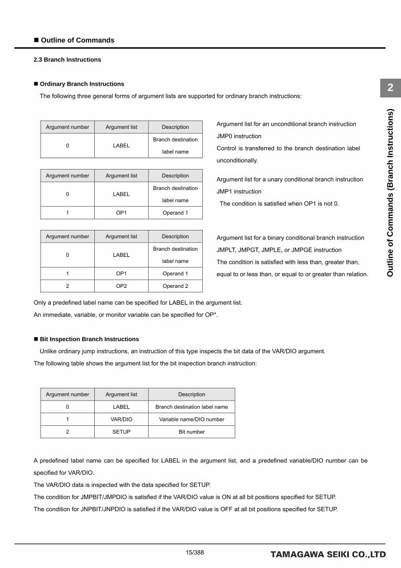
15/388
Outline of Commands
2
Out
line
of C
omm
ands
(Bra
nch
Inst
ruct
ions
)
Argument list for an unconditional branch instruction
JMP0 instruction
Control is transferred to the branch destination label
unconditionally.
Argument list for a unary conditional branch instruction
JMP1 instruction
The condition is satisfied when OP1 is not 0.
Argument list for a binary conditional branch instruction
JMPLT, JMPGT, JMPLE, or JMPGE instruction
The condition is satisfied with less than, greater than,
equal to or less than, or equal to or greater than relation.
2.3 Branch Instructions
Ordinary Branch Instructions
The following three general forms of argument lists are supported for ordinary branch instructions:
Only a predefined label name can be specified for LABEL in the argument list.
An immediate, variable, or monitor variable can be specified for OP*.
Bit Inspection Branch Instructions
Unlike ordinary jump instructions, an instruction of this type inspects the bit data of the VAR/DIO argument.
The following table shows the argument list for the bit inspection branch instruction:
A predefined label name can be specified for LABEL in the argument list, and a predefined variable/DIO number can be
specified for VAR/DIO.
The VAR/DIO data is inspected with the data specified for SETUP.
The condition for JMPBIT/JMPDIO is satisfied if the VAR/DIO value is ON at all bit positions specified for SETUP.
The condition for JNPBIT/JNPDIO is satisfied if the VAR/DIO value is OFF at all bit positions specified for SETUP.
Argument number Argument list Description
0 LABEL Branch destination
label name
Argument number Argument list Description
0 LABEL Branch destination
label name
1 OP1 Operand 1
Argument number Argument list Description
0 LABEL Branch destination
label name
1 OP1 Operand 1
2 OP2 Operand 2
Argument number Argument list Description
0 LABEL Branch destination label name
1 VAR/DIO Variable name/DIO number
2 SETUP Bit number

16/388
Outline of Commands
2
Out
line
of C
omm
ands
(Bra
nch
Inst
ruct
ions
)
A conditional branch is caused according to the
move statuses of all axes in the mechanism.
JMPMCH instruction
A conditional branch is caused according to the
move status of each axis in the mechanism.
JMPAXIS instruction
Move Status Branch Instructions
Unlike ordinary jump instructions, an instruction of this type causes a conditional branch according to the move status of all
axes or each axis in the mechanism.
The following table shows the argument list for the move status branch instruction:
Only a predefined label name can be specified for LABEL in the argument list.
An immediate value or variable can be specified for MCH, SETUP, and PASS.
The following is a list of PASS points:
PASS point value PASS point
1 Interpolation calculation in progress
2 Deceleration in progress
4 Axis moving
8 Homing
If an illegal value is set to a PASS point, an alarm (at the task level) occurs.
Subroutine Call Instructions
The SVC supports the CALL command as a subroutine call instruction. When a CALL command is executed, the next index
is pushed to the stack for control transfer to the branch destination label. When a RET instruction is executed, the return
destination is popped from the stack for control transfer to its index.
Argument number Argument list Description
0 LABEL Branch destination
label name
1 MCH Mechanism number
2 PASS PASS point
Argument number Argument list Description
0 LABEL Branch destination
label name
1 MCH Mechanism number
2 SETUP Setup axis number
3 PASS PASS point

17/388
Outline of Commands
2
Out
line
of C
omm
ands
(PA
SS In
stru
ctio
ns)
2.4 PASS Instructions
PASS Points
The SVC has 4 PASS points in a move instruction: interpolation calculation in progress, acceleration/deceleration in
progress, axis moving, and homing.
The following figure illustrates the meaning of each PASS point (excluding “homing”).

18/388
Outline of Commands
2
Out
line
of C
omm
ands
(PA
SS In
stru
ctio
ns)
Interpolation Calculation in Progress
At this PASS point, interpolation calculation for position data is in progress in the SVC.
If a value is set to the acceleration/deceleration filter even after interpolation calculation has been completed, the axis
remains moving until data is delivered from the filter.
The PASS point at which interpolation calculation is in progress is used when a compound move command is used.
When interpolation calculation is in progress, the “acceleration/deceleration in progress” and “axis moving” statuses are also
set to ON.
Acceleration/Deceleration in Progress
At this PASS point, data delivery from the acceleration/deceleration filter has not yet been completed in the SVC.
The PASS point at which acceleration/deceleration is in progress is used for moves that need not wait for the axis to be
placed in position.
Equipment operation time can be reduced by using this PASS point.
When acceleration/deceleration is in progress, the “axis moving” status is also set to ON.
Axis Moving
At this PASS point, the in-position signal is OFF once data has been delivered from the acceleration/deceleration filter.
The PASS point at which the axis moving is in progress is used when the next program needs to be executed following a wait
for in-position operation.
Types of PASS Instructions
There are two types of PASS instructions: the PASSM, DECELM, INPOSM, and ORGM instructions that specify PASS
points for all the axes belonging to a mechanism, and the PASSA, DECELA, INPOSA, and ORGA instructions that specify a
PASS point for each of the axes belonging to a mechanism. The following table describes each PASS instruction:
Unlike the JMPMCH and JMPAXIS branch instructions, PASS instructions avoid the need for branch destination labels to be
specified and thus simplify program coding when the program is executed following a wait for a PASS point.
All axes in a
mechanism
Each axis in a
mechanism
PASS point Description
PASSM PASSA Interpolation calculation
in progress
Wait at the current index if interpolation calculation is in
progress.
DECELM DECELA Acceleration/deceleratio
n in progress
Wait at the current index if acceleration/deceleration is in
progress.
INPOSM INPOSA Axis moving Wait at the current index if the axis is moving.
ORGM ORGA Homing Wait at the current index if homing is in progress.

19/388
Outline of Commands
2
Out
line
of C
omm
ands
(Ser
vo In
stru
ctio
ns)
2.5 Servo Instructions
Servo Instructions
Servo instructions include SVMODE to set the driver control mode, SVVEL to set the speed for speed control, SVCUR to
set the electric current value for torque control, and SVPRM2 to change driver parameters, in addition to the SVON (servo on),
SVOFF (servo off), and SVFREE (servo free) instructions.
Servo On, Servo Off, and Servo Free Instructions
After a servo on instruction (SVON command) has been executed, wait 500 ms or more before moving axes, with
consideration given to the time for initialization of the interpolation data and the acceleration/deceleration filter. If an SVON
command is executed for an axis that is already moving, the axis stops moving. The following is an argument list for the
SVON command:
As is the case with move commands, bits 0 to 31 of a setup axis number correspond to Axes 1 to 32.
The same applies to the SVOFF and SVFREE commands.
Servo Parameter Instructions
The SVPRM2, SVMODE, SVVEL, and SVCUR commands transfer parameters to a driver. Unlike move instructions and
servo on instructions, a servo parameter instruction can set only one axis at a time. The following is an argument list for the
SVPRM2 command:
For the AXIS argument, specify an axis number belonging to the mechanism. For example, to set Axis 1, specify 1, and to set
Axis 3, specify 3. Only one axis can be set at a time. To set data for multiple axes, execute the command multiple times.
Argument number Argument list Description
0 MCH Mechanism number
1 SETUP Setup axis number
Argument number Argument list Description
0 MCH Mechanism number
1 AXIS Axis number
2 ID Data ID
3 DATA Data value

20/388
Outline of Commands
2
Out
line
of C
omm
ands
(Tim
er In
stru
ctio
ns)
2.6 Timer Instructions
Timer Instructions
A program can use 32 timers. The maximum timer value is 2147483647. The timer counts up in increments of 1 msec,
stopping when the maximum timer value has been reached. Two timer instructions are available: WAIT (simple wait) and
TIME (timer instruction).
Simple Wait Instruction
The simple wait instruction (WAIT command) can use 1 timer in a program. When multiple tasks are used in simple wait
mode, make sure that the same timer number is not specified repeatedly. The following is an argument list for the simple wait
instruction (WAIT command):
Timer Instruction
The timer instruction (TIME command) can set a timer preset value (initial value). When the monitor variable TIM[*] is used,
the timer instruction can be used in a branch instruction or arithmetic instruction with no change required. The following is an
argument list for the timer instruction (TIME command):
An immediate, variable, or monitor variable can be specified for OP1.
Argument number Argument list Description
0 TIMER Timer number
1 WAIT Wait time (msec)
Argument number Argument list Description
0 TIMER Timer number
1 OP1 Timer initial value

21/388
Outline of Commands
2
Out
line
of C
omm
ands
(I/O
Inst
ruct
ions
)
2.7 I/O Instructions
I/O Instructions
Data of the DIO board installed on the SVC is referenced and set by I/O instructions. Two types of I/O instructions are
provided: the DIN and DOUT instructions to handle all the bits of the DIO data, and the BITIN, BITON, and BITOFF
instructions to handle the desired bits of the DIO data.
I/O Input Instructions (DIN and BITIN)
The DIN instruction stores all the bits of the DIO data in a variable. To obtain only the desired bits, use the BITIN instruction
and set those bits to the MASK argument. The following are argument lists for the DIN and BITIN instructions:
• List of DIN instruction arguments
• List of BITIN instruction arguments
* Bit data set to 1 by the MASK argument is stored in the variable.
I/O Output Instructions (DOUT, BITON, and BITOFF)
The DOUT instruction sets data to all the bits of DIO. To output only the desired bits by the DOUT instruction, use the
monitor variable DO[*] for data manipulation and then execute the DOUT instruction. To output data to the desired bits, use
the BITON and BITOFF instructions. The following is an argument list for the DOUT, BITON, and BITOFF instructions:
• List of the arguments of the DOUT, BITON, and BITOFF instructions
* Although the argument list is the same as for the DOUT, BITON, and BITOFF instructions, the BITON and BITOFF
instructions handle (turn ON and OFF) only the bits set to 1 in the output data.
Argument number Argument list Description
0 VAR Variable
1 DIO DIO number
Argument number Argument list Description
0 VAR Variable
1 DIO DIO number
2 MASK Input mask
Argument number Argument list Description
0 DIO DIO number
1 OP1 Output data

22/388
Outline of Commands
2
Out
line
of C
omm
ands
(I/O
Inst
ruct
ions
)

23/388
Description of the Program Grid
3
Edit
Func
tion
of th
e Pr
ogra
m G
rid
3. Description of the Program Grid
3.1 Edit Function of the Program Grid
The following is an example of the program grid initial screen:
Variable List Grid Argument List Grid Program Step Grid
Subpane Tool Pane
File Pane

24/388
Description of the Program Grid
3
Edit
Func
tion
of th
e Pr
ogra
m G
rid
Program Step Grid
The program step grid displays a program listing. This grid has the following columns: 【No.】, 【LABEL】, 【CMG】, and
【CMD】.
•【No.】 : Displays the line numbers of the program list. The program is executed in ascending order (starting
from the top line).
•【LABEL】 : This column is used to set branch labels for branch instructions and others. Enter label names.
•【CMG】 : This column is used to select the type of command. A list of the SVC commands classified by the
command type is displayed.
E.g. Servo instruction: Servo; Absolute position move instruction: Mova
Select a command type from the list. You cannot do this by entering text.
•【CMD】 : Displays a list of the commands selected in the 【CMG】 column.
Select a command from the list. You cannot do this by entering text.
Argument List Grid
The argument list grid displays a list of the arguments for the command currently selected on the program step grid. This
grid has the following columns: 【No.】, 【Name】, and 【Value】.
•【No.】 : Displays the line numbers of the argument list. The number of arguments varies according to the
command.
•【Name】 : Displays the argument names in the argument list. E.g. Mechanism number: MCH; Axis 1 set:
SETUP; Target position: P1
•【Value】 : Displays the argument numbers. Enter argument values.
Variable List Grid
The variable list grid displays a list of the variables to be used in the program. This grid has the following columns: 【No.】,
【Name】, 【Value】, and 【Comment】.
•【No.】 : Displays the line numbers of the variable list.
•【Name】 : Displays variable names. Enter variable names.
•【Value】 : Displays the initial values of the variables. Enter initial values.
•【Comment】 : Displays comments. Enter comments.

25/388
Description of the Program Grid
3
Edit
Func
tion
of th
e Pr
ogra
m G
rid
File Pane
The file pane displays the currently created program or programs to be created. The parent tree node displays program file
names; the child tree node displays the files split under any names by the user. Initially, the program file name is 【New
Program】 and the split file name is 【Main】. A maximum of four program files can be displayed. Addition or deletion of a
program file, or renaming, addition, or deletion of a split file can be specified by a shortcut menu (right click). The shortcut
menu items are listed below. The shortcut menu for the parent tree node is different from that for a child tree node.
Shortcut Menu for Parent Tree Node (Program File)
Shortcut Menu for Child Tree Node (Split File)
* When multiple programs are displayed in the file pane, the background of the currently active program is highlighted.
The program selected on the tree is activated automatically.
Button name Function
New File Creates a new program file.
Open File Opens an existing program file.
Save File Saves a created program file.
Add File Adds a program file to the file pane.
Delete File Deletes a program file from the file pane.
Build Builds a created program.
Down load Downloads the object file to the SVC after the build has been performed.
Button name Function
ReName Renames a split file.
Add Asm Adds a split file to the tree.
Delete Asm Deletes a split file from the tree.
Move On Moves a split file to the upper tree.
Move Under Moves a split file to the lower tree.

26/388
Description of the Program Grid
3
Edit
Func
tion
of th
e Pr
ogra
m G
rid
Tool Pane
The tool pane contains the function buttons used for the program grid.
The buttons are grouped according to functions. The following table describes the tool pane functions:
Group name Button name Function
New Creates a new program file.
Open Opens an existing program file.
Save Saves a created program file. File
Flash Saves a downloaded program to FLASH memory of the SVC.
Undo Undoes an edit.
Redo Redoes an edit.
Copy Copies the selected range.
Cut Cuts the selected range.
Paste Pastes the copied data.
Insert Paste Pastes the copied data after inserting a line.
Insert Inserts a line.
Edit
Delete Deletes a line.
Build Builds a created program.
Down load Downloads the object file to the SVC after the build has been performed.
Collation Checks the program currently displayed against the program in the SVC.
Start Executes a program.
Starts Task 0 and executes it beginning with address 0 of the command
memory.
Build
Stop Stops the task after the progress step has been executed.
SVON Turns servo ON for all axes.
SVOFF Turns servo OFF for all axes.
SVFREE Performs Servo-FREE for all axes. Differs from Servo-OFF in that this
function releases the brake if a motor with a brake is being used.
ALMRST Resets the alarm.
CMD
STOP Stops deceleration for all axes.

27/388
Description of the Program Grid
3
Edit
Func
tion
of th
e Pr
ogra
m G
rid
Details of the Edit Functions
The edit functions (copy, paste, etc.) of the program grid differ from those of commonly used applications such as Excel in
that they are optimized for the editing of programs. The following table describes the operations of the edit functions:
Copy Function
Command Condition Program step Argument list Variable list
Select a single cell. The step data of the selected cell line is copied.
The argument values of the selected cell are copied. (Excluding the 【No.】 and 【Name】 columns.)
The selected cell is copied. (Excluding the 【No.】 column.)
Select a line header. The step data of the selected lines is copied.
The 【Value】 column values of the selected lines are copied.
The values of all columns except 【No.】 of the selected lines are copied.
Select multiple cells. (contiguous)
The step data of the selected cells is copied.
The argument values of the selected cells are copied. (Selection of the 【No.】 and 【Name】 columns is invalid.)
The values of the selected cells are copied. (Selection of the 【No.】 column is invalid.)
Select multiple cells. (non-contiguous)
Error. The argument values of the selected cells are copied. (Selection of the 【No.】 and 【Name】 columns is invalid.)
The values of the selected cells are copied. (Selection of the 【No.】 column is invalid.)
Select multiple line headers. (contiguous)
The step data of the selected lines is copied.
The 【Value】 column values of the selected lines are copied.
The values of all columns except 【No.】 of the selected lines are copied.
Copy
Select multiple line headers. (non-contiguous)
Error. The 【Value】 column values of the selected lines are copied.
The values of all columns except 【No.】 of the selected lines are copied.
Group name Button name Function
Override【Track】 Executes speed override in the range of 0% to 100%.
Override【+】 Executes speed override in the range of 0% to 100%. Override
Override【-】 Executes speed override in the range of 0% to 100%.
Program Mode Switches between debug mode and normal mode.
Task View Highlights the current step.
Break Sets breakpoints.
Release Resets the breakpoints.
ReStart After program execution has been suspended at a breakpoint, restarts the
program from the step during which the suspension took place.
Debug
Step In After program execution has been suspended at a breakpoint, step-executes
the program from the step during which the suspension took place.
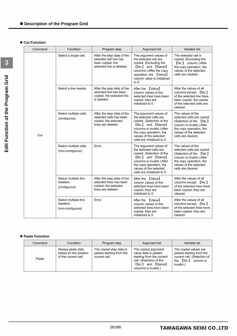
28/388
Description of the Program Grid
3
Edit
Func
tion
of th
e Pr
ogra
m G
rid
Cut Function
Command Condition Program step Argument list Variable list
Select a single cell. After the step data of the selected cell line has been copied, the selected line is deleted.
The argument values of the selected cell are copied. (Excluding the 【No.】 and 【Name】 columns.) After the copy operation, the 【Value】 column value is initialized to 0.
The selected cell is copied. (Excluding the 【No.】 column.) After the copy operation, the values of the selected cells are cleared.
Select a line header. After the step data of the selected line has been copied, the selected line is deleted.
After the 【Value】 column values of the selected lines have been copied, they are initialized to 0.
After the values of all columns except 【No.】 of the selected line have been copied, the values of the selected cells are cleared.
Select multiple cells. (contiguous)
After the step data of the selected cells has been copied, the selected lines are deleted.
The argument values of the selected cells are copied. (Selection of the 【No.】 and 【Name】 columns is invalid.) After the copy operation, the values of the selected cells are initialized to 0.
The values of the selected cells are copied. (Selection of the 【No.】 column is invalid.) After the copy operation, the values of the selected cells are cleared.
Select multiple cells. (non-contiguous)
Error. The argument values of the selected cells are copied. (Selection of the 【No.】 and 【Name】 columns is invalid.) After the copy operation, the values of the selected cells are initialized to 0.
The values of the selected cells are copied. (Selection of the 【No.】 column is invalid.) After the copy operation, the values of the selected cells are cleared.
Select multiple line headers. (contiguous)
After the step data of the selected lines has been copied, the selected lines are deleted.
After the 【Value】 column values of the selected lines have been copied, they are initialized to 0.
After the values of all columns except 【No.】 of the selected lines have been copied, they are cleared.
Cut
Select multiple line headers. (non-contiguous)
Error. After the 【Value】 column values of the selected lines have been copied, they are initialized to 0.
After the values of all columns except 【No.】 of the selected lines have been copied, they are cleared.
Paste Function
Command Condition Program step Argument list Variable list
Paste
Always paste data based on the position of the current cell.
The copied step data is pasted starting from the current cell.
The copied argument value data is pasted starting from the current cell. (Selection of the 【No.】 and 【Name】 columns is invalid.)
The copied values are pasted starting from the current cell. (Selection of the 【No.】 column is invalid.)

29/388
Description of the Program Grid
3
Edit
Func
tion
of th
e Pr
ogra
m G
rid
Insert Line/Delete Line Function
Command Condition Program step Argument list Variable list
Insert
Insert the line of the selected cell. (If multiple cells have been selected, insert the lines of those cells.) Note that this function permits contiguous selection only. Non-contiguous selection is not permitted.
Permitted. Invalid. Permitted.
Delete
Delete the line of the selected cell. (If multiple cells have been selected, use the same operation as that for Insert Line.)
Permitted. Invalid. Permitted.
DEL Key Function
Command Condition Program step Argument list Variable list
Select a single cell. The data of the selected cell is cleared. If a cell in the 【LABEL】 column is selected, the label is cleared. If one cell in either the 【CMG】 column or the 【CMD】 column is selected, the cells of both columns are cleared. (The 【No.】 column cannot be cleared.)
The data of the selected cell is cleared to 0. (This applies only to the 【Value】 column.)
The data of the selected cell is cleared. (The 【No.】 column cannot be cleared.)
Select a line header. All the values of all columns except 【No.】 of the selected line are cleared.
The 【Value】 column values of the selected line are cleared to 0.
All the values of all columns except 【No.】 of the selected line are cleared.
Select multiple cells. (contiguous)
The values of the selected cells are cleared. (For the selection of 【CMG】 and 【CMD】columns, the same operation as that for “Select a single cell” is used.)
The same operation as that for “Select a single cell” is used.
The same operation as that for “Select a single cell” is used.
Select multiple cells. (non-contiguous)
All the values of all columns except 【No.】 of the selected line are cleared.
The 【Value】 column values of the selected line are cleared to 0.
All the values of all columns except 【No.】 of the selected line are cleared.
Select multiple line headers. (contiguous)
The same operation as that for “Select a line header” is used.
The same operation as that for “Select a line header” is used.
The same operation as that for “Select a line header” is used.
DEL Key
Select multiple line headers. (non-contiguous)
The same operation as that for “Select a line header” is used.
The same operation as that for “Select a line header” is used.
The same operation as that for “Select a line header” is used.
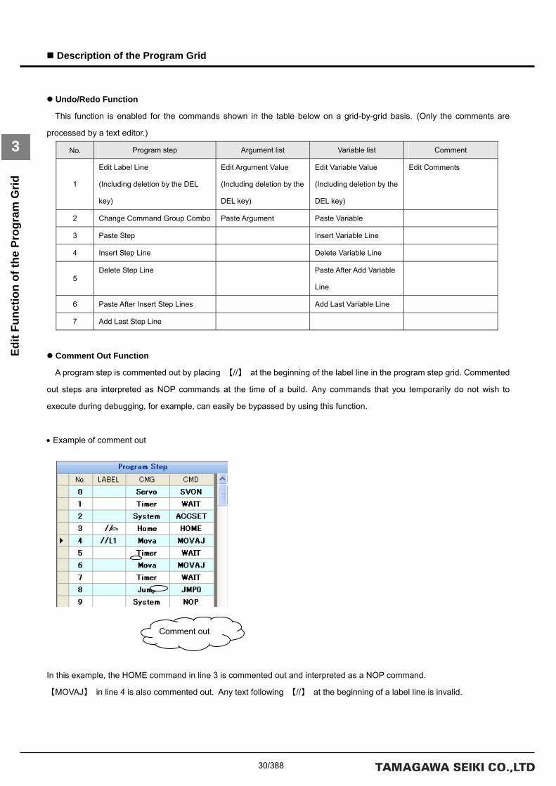
30/388
Description of the Program Grid
3
Edit
Func
tion
of th
e Pr
ogra
m G
rid
Undo/Redo Function
This function is enabled for the commands shown in the table below on a grid-by-grid basis. (Only the comments are
processed by a text editor.)
No. Program step Argument list Variable list Comment
1
Edit Label Line
(Including deletion by the DEL
key)
Edit Argument Value
(Including deletion by the
DEL key)
Edit Variable Value
(Including deletion by the
DEL key)
Edit Comments
2 Change Command Group Combo Paste Argument Paste Variable
3 Paste Step Insert Variable Line
4 Insert Step Line Delete Variable Line
5 Delete Step Line Paste After Add Variable
Line
6 Paste After Insert Step Lines Add Last Variable Line
7 Add Last Step Line
Comment Out Function
A program step is commented out by placing 【//】 at the beginning of the label line in the program step grid. Commented
out steps are interpreted as NOP commands at the time of a build. Any commands that you temporarily do not wish to
execute during debugging, for example, can easily be bypassed by using this function.
• Example of comment out
In this example, the HOME command in line 3 is commented out and interpreted as a NOP command.
【MOVAJ】 in line 4 is also commented out. Any text following 【//】 at the beginning of a label line is invalid.
Comment out

31/388
Description of the Program Grid
3
Edit
Func
tion
of th
e Pr
ogra
m G
rid
List of Shortcut Keys for the Program Grid
Key operation Function
CTRL+Z Undo
CTRL+Y Redo
CTRL+C Copy
CTRL+X Cut
CTRL+V Paste
CTRL+I Paste After Insertion
Insert Insert Line
SHIFT+Delete Delete Line
F5 Execute Program
F6 Download
F7 Display Task Trace Line At Beginning
F8 Display and Execute Task Trace
F9 Set/Reset Breakpoint
F11 Step-in
F12 Switch Debug Mode
SHIFT+F5 Stop Program

32/388
Description of the Program Grid
3
Edit
Func
tion
of th
e Pr
ogra
m G
rid
Subpane
The subpane contains convenient functions other than the program edit functions. The following table describes the
subpane functions:
Tab name Function
Comment Displays comments on the currently selected program step.
Help Displays help for the currently selected program command.
Find Searches a program for a character string.
Outpot Outputs the results of a build and check.
Error List Outputs error information if a build fails.
Gain Adjusts the servo gain of each axis.
Watch Supervises the values of defined variables.
Monitor Displays the mechanism, servo, and I/O monitor windows.
Task Displays the task status.
DIO Performs I/O operations.
Jog Performs JOG operation and step operation.
Comments Pane
The comments pane is a text editor in which comments can be input. Input comments for each program step. The comment
text is automatically switched when another program step is selected.

33/388
Description of the Program Grid
3
Edit
Func
tion
of th
e Pr
ogra
m G
rid
Help Pane
The help pane is used to display help for the currently selected command. Help information is automatically switched when
another command is selected. * Turn ON the help display function of 【Utility】 to use this function.
Search Pane
The search pane is used to search a program for a character string. Enter a search string in the combo list and then click
【SEARCH】. For the searchable ranges, see the following table:
• Toolbar
【SEARCH】 Starts search for the contents currently displayed in the search list box.
【Searched List box】 Used to enter the character string to be searched for.
When the list box is expanded, a list of the character strings searched for thus far is
displayed.

34/388
Description of the Program Grid
3
Edit
Func
tion
of th
e Pr
ogra
m G
rid
• Grid
【No.】 Displays the search result number.
【Value】 Displays phrases containing the search string.
【Grid】 Displays the grids of strings that matched the search condition.
【Step No.】 Displays the program line numbers of strings that matched the search condition.
【Arg No.】 Displays the argument numbers of strings that matched in the argument list.
【Var No.】 Displays the line numbers of strings that matched in the variable list.
• Searchable ranges
Program step Argument list Variable list
Labels, command types, and
commands can be searched for a
character string. (Line numbers are
excluded from the search range.)
Argument values can be searched for a
character string. (Argument numbers
and argument names are excluded
from the search range.)
Variable names and initial values can
be searched for a character string.
(Variable line numbers and comments
are excluded from the search range.)
Output Pane
The output pane displays the results of a build and check.

35/388
Description of the Program Grid
3
Edit
Func
tion
of th
e Pr
ogra
m G
rid
Error Information Pane
The error information pane displays error information about build results.
• Grid
【Icon】 Displays error icons.
【Error Code】 Displays associated error codes.
【Explanation】 Displays error descriptions.
【Error Word】 Displays the character string or strings that caused the error.
【Row】 Displays the program line numbers in which the error occurred.
【Note】 Displays supplementary information about errors.

36/388
Description of the Program Grid
3
Edit
Func
tion
of th
e Pr
ogra
m G
rid
Gain Pane
The gain pane is used to adjust the gain of each axis. Gains can be changed even during program execution.
• Toolbar
【Axis selection combo】 Selects an axis number for which the gain is changed.
【SAVE FLASH】 Saves the changed gain data in the flash memory of the driver.
*Note:
Stop any running program before saving gain data.
• Slider
【Kp1】 Changes the value of position loop proportional gain 1.
【Kv1】 Changes the value of speed loop proportional gain 1.
【Ki1】 Changes the value of speed loop integral gain 1.
【LPF_f】 Changes the value of the lowpass filter cutoff frequency.
【NF_f】 Changes the value of the notch filter center frequency.
【NF_d】 Changes the value of the notch filter attenuation.
【LOAD】 Changes the value of the load inertia.
For details on the gain items, refer to the instruction manual for the driver.

37/388
Description of the Program Grid
3
Edit
Func
tion
of th
e Pr
ogra
m G
rid
Supervision Pane
The supervisory pane is used to monitor the values of variables used in the program. The variable list is displayed
automatically, allowing the user to reference or set variables after the program has been downloaded.
• Toolbar
【COUNT】 Displays the number of predefined variables.
【B(Back)】 Up to 100 variables can be monitored at a time. This button displays the previous list.
If the first list is being displayed, pressing this button has no effect.
【Variable list】 Displays the number of the currently displayed variable list. Variable list numbers are assigned
according to the order in which the variables are defined.
【G(Go)】 Up to 100 variables can be monitored at a time. This button displays the next list.
If the last list is being displayed, pressing this button has no effect.
【HEX】 Displays all variable values in hexadecimal notation.
【DEC】 Displays all variable values in decimal notation.
• Grid
【No.】 Displays the variable list numbers.
【Name】 Displays the names of predefined variables.
【Value】 Displays the variable values after data has been read.
【Data Type】 Switches the data type of a variable value. Checked: Hexadecimal notation; Unchecked: Decimal
notation
【Note】 Displays comments for the variable.

38/388
Description of the Program Grid
3
Edit
Func
tion
of th
e Pr
ogra
m G
rid
Monitor Pane
The monitor pane is used to monitor data for the controller (mechanism), driver, and I/O. This pane is displayed
automatically after the controller has been connected.
• Toolbar
【UNIT】 Switches the position data of the servo monitor between the controller instruction unit and the motor unit
(Pulse).
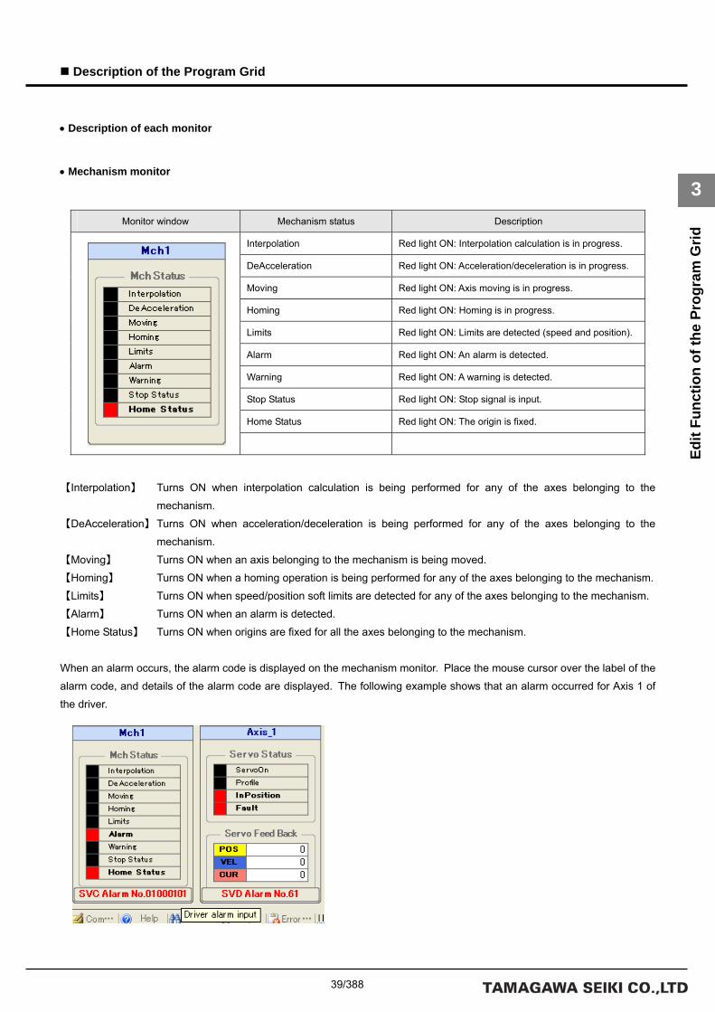
39/388
Description of the Program Grid
3
Edit
Func
tion
of th
e Pr
ogra
m G
rid
• Description of each monitor
• Mechanism monitor
【Interpolation】 Turns ON when interpolation calculation is being performed for any of the axes belonging to the
mechanism.
【DeAcceleration】 Turns ON when acceleration/deceleration is being performed for any of the axes belonging to the
mechanism.
【Moving】 Turns ON when an axis belonging to the mechanism is being moved.
【Homing】 Turns ON when a homing operation is being performed for any of the axes belonging to the mechanism.
【Limits】 Turns ON when speed/position soft limits are detected for any of the axes belonging to the mechanism.
【Alarm】 Turns ON when an alarm is detected.
【Home Status】 Turns ON when origins are fixed for all the axes belonging to the mechanism.
When an alarm occurs, the alarm code is displayed on the mechanism monitor. Place the mouse cursor over the label of the
alarm code, and details of the alarm code are displayed. The following example shows that an alarm occurred for Axis 1 of
the driver.
Monitor window Mechanism status Description
Interpolation Red light ON: Interpolation calculation is in progress.
DeAcceleration Red light ON: Acceleration/deceleration is in progress.
Moving Red light ON: Axis moving is in progress.
Homing Red light ON: Homing is in progress.
Limits Red light ON: Limits are detected (speed and position).
Alarm Red light ON: An alarm is detected.
Warning Red light ON: A warning is detected.
Stop Status Red light ON: Stop signal is input.
Home Status Red light ON: The origin is fixed.

40/388
Description of the Program Grid
3
Edit
Func
tion
of th
e Pr
ogra
m G
rid
• Servo monitor
【ServoOn】 Turns ON when servo is on.
【Profile】 Turns ON when profiling is in progress.
【InPosition】 Turns ON during in-position operation.
【Fault】 Turns ON when an alarm is detected.
【POS】 Displays the present actual position of the motor.
【VEL】 Displays the present actual speed of the motor.
【CUR】 Displays the present actual electric current of the motor.
• I/O monitor
【IN_0 to IN_15】 Displays the input data of the DIO. The red light turns ON when input is ON.
【OUT_0 to OUT_15】 Displays the output data of the DIO. The red light turns ON when output is ON.
Monitor window Servo status Description
ServoOn Red light ON: Servo is on.
Profile Red light ON: Profiling is in progress.
InPosition Red light ON: In-position operation.
Fault Red light ON: An alarm is detected.
Servo feedback Description
POS Present actual position of the motor
VEL Present actual speed of the motor
CUR Present actual electric current of the motor
Monitor window DIO status Description
IN_0 to IN_15 Red light ON: DIO input data
OUT_0 to OUT_15 Red light ON: DIO output data

41/388
Description of the Program Grid
3
Edit
Func
tion
of th
e Pr
ogra
m G
rid
Task Pane
The task pane is used to monitor the task status. This pane is displayed automatically after the controller has been
connected.
.
• Task monitor
【STATUS】 Displays the starting status of the task. If the task is being executed, the background color changes to
red and the character string changes to “RUN.”
【INDEX】 Displays the current index of the task.
【STACK】 Displays the current stack pointer of the task.
【Debug Color】 Sets the background color for when a task trace is displayed in debug mode.
Monitor window Task status Description
STATUS Displays “RUN” when the task is being executed.
INDEX Displays the current index of the task.
STACK Displays the current stack pointer of the task.
Debug background color Description
Debug Color Displays the background color for debug mode.

42/388
Description of the Program Grid
3
Edit
Func
tion
of th
e Pr
ogra
m G
rid
DIO Pane
The DIO pane is used for DIO operation. This pane is displayed automatically after the controller has been connected.
Unlike the I/O monitor of the monitor pane, the status is output directly to the I/O device by clicking a label of an 【OUT】
group.
• DIO control
• About label definition of the SV Programmer
The SV Programmer allows you to define labels for I/O bit numbers and other system-specific assignments.
To define a label, use 【Label Setup】 under 【Utility】 of the main menu. Since the label information is saved in the project
file, open the project file before using label information.
Monitor window DIO status Description
IN group Red light ON: DIO input data
OUT group Red light ON: DIO output data

43/388
Description of the Program Grid
3
Edit
Func
tion
of th
e Pr
ogra
m G
rid
JOG Pane
The JOG pane is used for JOG operation and step operation. This pane is displayed automatically after the controller has
been connected.
• JOG control
Monitor window Speed label Description
300 [rpm] Sets the speed of JOG/step operation to 300 rpm.
100 [rpm] Sets the speed of JOG/step operation to 100 rpm.
50 [rpm] Sets the speed of JOG/step operation to 50 rpm.
10 [rpm] Sets the speed of JOG/step operation to 10 rpm.
Mode Description
Jog・Step Switches between JOG operation and step operation.
Step Sets the move distance in step operation mode.
Position Displays the present position.
Unit Switches between instruction unit and motor unit (pulse).
Command Description
Turns the servo ON.
Turns the servo OFF.
Resets the alarm.
Sets the present position to 0.
Rotates the motor in the reverse direction while the
button is held down.
Rotates the motor in the forward direction while the
button is held down.

44/388
Specification for the Program Grid
3
Synt
ax S
peci
ficat
ions
for t
he P
rogr
am G
rid
3.2 Syntax Specifications for the Program Grid
How to Specify an Immediate
The SVC supports only a signed 32-bit integer type to be used to specify an immediate as an initial value of a command
argument or variable. If the specified value is not a signed 32-bit integer, an error is returned. In addition, immediates can be
specified in decimal or hexadecimal notation. The following table shows the range of specifiable immediates and an example
value for each notation:
Notation Range Example
Decimal integer -2147483648 to 2147483647 123456789
Hexadecimal integer 0x80000000 to 0x7FFFFFFF 0x12345678
How to Specify a Label
The branch destination label used for a conditional branch instruction or others must be defined in the 【LABEL】 column
of the program step grid as shown below:
Item Contents
Character
position
Valid characters Description
First character [ _ ] [ A - Z ] [ a - z ] Only single-width alphabetic characters and
underscore can be specified. Valid characters for
labels Second
character and
after
[ _ ] [ 0 - 9 ] [ A - Z ] [ a - z ] Only single-width alphanumeric characters
and underscore can be specified.
Maximum number of
characters allowed for
a label name
32
Case Case insensitive. Uppercase and lowercase versions of a label name are considered to be identical.
First/last characters Blank characters (single-width spaces and tab characters) at the start or end of a label character string
are ignored.
Label definition Labels that are not defined in the 【LABEL】 column of the program step grid cannot be used as
command arguments.
Repeated definition Repeated definition of a label or use of a variable name or reserved characters as a label name must be
avoided.
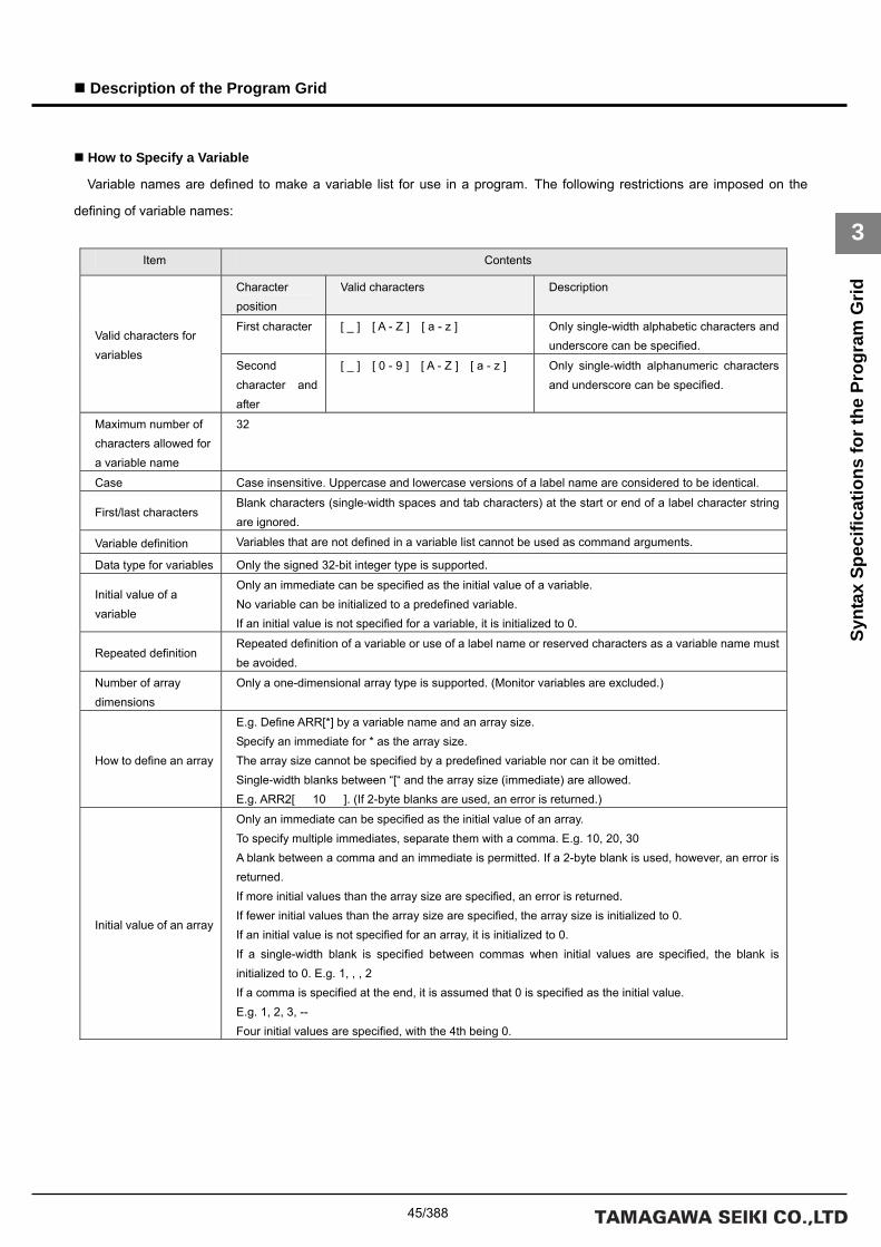
45/388
Description of the Program Grid
3
Synt
ax S
peci
ficat
ions
for t
he P
rogr
am G
rid
How to Specify a Variable
Variable names are defined to make a variable list for use in a program. The following restrictions are imposed on the
defining of variable names:
Item Contents
Character position
Valid characters Description
First character [ _ ] [ A - Z ] [ a - z ] Only single-width alphabetic characters and underscore can be specified.
Valid characters for variables
Second character and after
[ _ ] [ 0 - 9 ] [ A - Z ] [ a - z ] Only single-width alphanumeric characters and underscore can be specified.
Maximum number of characters allowed for a variable name
32
Case Case insensitive. Uppercase and lowercase versions of a label name are considered to be identical.
First/last characters Blank characters (single-width spaces and tab characters) at the start or end of a label character string are ignored.
Variable definition Variables that are not defined in a variable list cannot be used as command arguments.
Data type for variables Only the signed 32-bit integer type is supported.
Initial value of a variable
Only an immediate can be specified as the initial value of a variable. No variable can be initialized to a predefined variable. If an initial value is not specified for a variable, it is initialized to 0.
Repeated definition Repeated definition of a variable or use of a label name or reserved characters as a variable name must be avoided.
Number of array dimensions
Only a one-dimensional array type is supported. (Monitor variables are excluded.)
How to define an array
E.g. Define ARR[*] by a variable name and an array size. Specify an immediate for * as the array size. The array size cannot be specified by a predefined variable nor can it be omitted. Single-width blanks between “[“ and the array size (immediate) are allowed. E.g. ARR2[ 10 ]. (If 2-byte blanks are used, an error is returned.)
Initial value of an array
Only an immediate can be specified as the initial value of an array. To specify multiple immediates, separate them with a comma. E.g. 10, 20, 30 A blank between a comma and an immediate is permitted. If a 2-byte blank is used, however, an error is returned. If more initial values than the array size are specified, an error is returned. If fewer initial values than the array size are specified, the array size is initialized to 0. If an initial value is not specified for an array, it is initialized to 0. If a single-width blank is specified between commas when initial values are specified, the blank is initialized to 0. E.g. 1, , , 2 If a comma is specified at the end, it is assumed that 0 is specified as the initial value. E.g. 1, 2, 3, -- Four initial values are specified, with the 4th being 0.

46/388
Specification for the Program Grid
3
Synt
ax S
peci
ficat
ions
for t
he P
rogr
am G
rid
Indirect Variable Reference
The SVC supports indirect variable reference for greater programming efficiency. To use indirect variable reference, the
address of a predefined variable needs to be assigned. To assign the address of a predefined variable, append an
ampersand to the front of the variable (e.g. &VAR). To reference that variable indirectly, append an asterisk to the front of the
variable name (e.g. *PTR). A programming example is shown below. The variables must be predetermined.
Command Argument 1 Argument 2 Description
ID VAR 1000 Assign immediate 1000 to variable VAR.
ID PTR &VAR Assign the address of variable VAR to variable PTR.
ID VAR2 *PTR Assign the indirect reference value of variable PTR to variable VAR2.
As a result, 1000 is assigned to VAR2.
The following is a programming example of how a value is referenced indirectly by using an array under the assumption
that ARR[10] is predefined:
Command Argument 1 Argument 2 Description
ID ARR[5] 1000 Assign immediate 1000 to variable ARR[5].
ID PTR &ARR[5] Assign the address of variable ARR[5] to variable PTR.
ID ARR[0] *PTR Assign the indirect reference value of variable PTR to variable ARR[0].
As a result, 1000 is assigned to variable ARR[0].

47/388
Description of the Program Grid
3
Synt
ax S
peci
ficat
ions
for t
he P
rogr
am G
rid
List of Monitor Variables
A monitor variable can be used for argument OP* of an arithmetic instruction or others. Monitor variables can cause a
branch to occur in a program according to the condition of the motor. The following is a list of monitor variables:
Variable name Description Meaning of the index
DI[*] Actual input DIO number
DO[*] Actual output DIO number
AI[*] Analog input AIN_CH number
AO[*] Analog output AOUT_CH number
TIM[*] Timer Timer number
TASK_STS[*] Task start status Task number
SVD_CPLS[*] Instructed position pulse (with no origin offset) SVD number
SVD_FPLS[*] Present position pulse (with no origin offset) SVD number
SVD_FVEL[*] Present actual speed (rpm) SVD number
SVD_FCUR[*] Present actual electric current (0.01 A) SVD number
SVD_STS[*] Servo status SVD number
SVD_ALM[*] Servo alarm SVD number
SVD_LOAD[*] Overload monitor (0.1%) SVD number
SVD_TEMP[*] Driver temperature (0.1°C) SVD number
SVD_PWR[*] Drive power supply voltage (0.1 V) SVD number
MCH_CPLS[*] [*] Instructed position (pulses) Mechanism number and axis number
MCH_FPLS[*] [*] Present position (pulses) Mechanism number and axis number
MCH_FCUR[*] [*] Present actual electric current (0.01 A) Mechanism number and axis number
MCH_FVEL[*] [*] Present actual speed (rpm) Mechanism number and axis number
MCH_FSPD[*] [*] Present actual speed (unit of speed) Mechanism number and axis number
MCH_CPOS[*] [*] Instructed position (instruction unit) Mechanism number and axis number
MCH_FPOS[*] [*] Present position (instruction unit) Mechanism number and axis number
MCH_SVSTS[*] [*] Servo status of each axis Mechanism number and axis number
MCH_SVALM[*] [*] Servo alarm of each axis Mechanism number and axis number
MCH_JSTS[*] [*] Move status of each axis Mechanism number and axis number
MCH_STS[*] Mechanism status Mechanism number
MCH_ALM[*] Mechanism alarm Mechanism number

48/388
Specification for the Program Grid
3
Synt
ax S
peci
ficat
ions
for t
he P
rogr
am G
rid
Details of Monitor Variables
Each monitor variable is described below.
DI[*]
Obtains the current actual input data. Specify a DIO number for the index of the monitor variable. The index of the first DIO
board is 0.
DO[*]
Obtains the current actual output data. Specify a DIO number for the index of the monitor variable. The index of the first
DIO board is 0.
AI[*] (Under development)
Obtains the current analog actual input data. Specify the channel number of the AIO for the index of the monitor variable.
The index of the AIO of the first channel is 0.
AO[*] (Under development)
Obtains the current analog actual output data. Specify an AIO channel number for the index of the monitor variable. The
index of the AIO of the first channel is 0.
TIM[*]
Obtains the timer value. The controller contains 32 timers. Specify a value of 0 to 31 for the index of the monitor variable.
An alarm (at the task level) is returned if any other index value is specified.
TASK_STS[*]
Obtains the current starting status of the task. The starting status is 1 if the task is active and 0 if the task is stopped.
Specify a task number for the index of the monitor variable.

49/388
Description of the Program Grid
3
Synt
ax S
peci
ficat
ions
for t
he P
rogr
am G
rid
SVD_CPLS[*]
Obtains the present instructed pulse of the driver, or specifically the value of the parameter ID36 【CommandPosition】 of
the driver. Specify an SVD number for the index of the monitor variable. The data obtained by this monitor variable does not
contain the origin offset data held within the controller. Data within the driver is obtained.
* Supplementary information about the SVD number
If the controller default settings are used, MAC-IDs are scanned automatically after power-on and SVD numbers and axis
numbers in the mechanism are assigned in ascending order of MAC-IDs. If the controller contains only one mechanism, the
axis numbers in the mechanism match the SVD numbers.
SVD_FPLS[*]
Obtains the present actual pulse of the driver, or specifically the value of the parameter ID40 【ActualPosition】 of the driver.
Specify an SVD number for the index of the monitor variable. The data obtained by this monitor variable does not contain the
origin offset data held within the controller. Data within the driver is obtained.
SVD_FVEL[*]
Obtains the present actual speed of the driver, or specifically the value of the parameter ID41 【ActualVelocity】 of the driver.
Specify an SVD number for the index of the monitor variable. The unit of the speed is rpm.
SVD_FCUR[*]
Obtains the present actual electric current of the driver, or specifically the value of the parameter ID42 【ActualCurrent】 of
the driver. Specify an SVD number for the index of the monitor variable. The unit of the electric current is 0.01 A.

50/388
Specification for the Program Grid
3
Synt
ax S
peci
ficat
ions
for t
he P
rogr
am G
rid
SVD_STS[*]
Obtains the present status of the driver, or specifically the value of the parameter ID20 【ServoStatus】 of the driver. Specify
an SVD number for the index of the monitor variable. The table below shows bit assignment for each status. For more
information, refer to the driver specifications.
• Contents of ServoStatus
Bit number Description
0 Servo on
1 Profiling is in progress.
2 In-position
3 Alarm detection
4 Forward direction soft limit
5 Reverse direction soft limit
6 Torque limit
7 Speed limit
8 Position deviation is excessive.
9
10 Homing
11 Gain select
12 Voltage of backup batteries dropped.
13
14
15
SVD_ALM[*]
Obtains the present error code of the driver, or specifically the value of the parameter ID22 【AlarmCode】 of the driver.
Specify an SVD number for the index of the monitor variable. For more information on the definition of error codes, refer to the
driver specifications.
SVD_LOAD[*]
Obtains the data of the overload monitor of the driver, or specifically the value of the parameter ID159 【Overload Monitor】
of the driver. Specify an SVD number for the index of the monitor variable. The unit of the monitor is 0.1%. For more
information on the data, refer to the driver specifications.

51/388
Description of the Program Grid
3
Synt
ax S
peci
ficat
ions
for t
he P
rogr
am G
rid
SVD_TEMP[*]
Obtains the present driver temperature of the driver, or specifically the value of the parameter ID160 【Driver Temp】 of the
driver. Specify an SVD number for the index of the monitor variable. The unit of the monitor is 0.1°C.
SVD_PWR[*]
Obtains the motor drive power supply of the driver, or specifically the value of the parameter ID161 【Power Voltage】 of the
driver. Specify an SVD number for the index of the monitor variable. The unit of the monitor is 0.1 V.
MCH_CPLS[*][*]
Obtains the present instructed pulse of each axis in the mechanism. Unlike SVD_CPLS[*], the monitor value contains the
origin offset data. The first index (left) specifies a mechanism number and the second specifies an axis number in the
mechanism.
MCH_FPLS[*][*]
Obtains the present actual pulse of each axis in the mechanism. Unlike SVD_FPLS[*], the monitor value contains the origin
offset data. The first index (left) specifies a mechanism number and the second specifies an axis number in the mechanism.
MCH_FCUR[*][*]
Obtains the present actual electric current of each axis in the mechanism. The data contents are the same as for
SVD_FCUR[*]. If the mechanism number and the axis number in the mechanism are different from SVD numbers, however,
the indexes need to be specified. The first index (left) specifies a mechanism number and the second specifies an axis
number in the mechanism.
MCH_FVEL[*][*]
Obtains the present actual speed of each axis in the mechanism. The data contents are the same as for SVD_FVEL[*]. If
the mechanism number and the axis number in the mechanism are different from SVD numbers, however, the indexes need
to be specified. The first index (left) specifies a mechanism number and the second specifies an axis number in the
mechanism.
MCH_FSPD[*][*]
Obtains the present actual speed of each axis in the mechanism. The data contents are different from those of
SVD_FVEL[*] and the monitor value is obtained in the instruction unit for speed set to the controller. The first index (left)
specifies a mechanism number and the second specifies an axis number in the mechanism.

52/388
Specification for the Program Grid
3
Synt
ax S
peci
ficat
ions
for t
he P
rogr
am G
rid
MCH_CPOS[*][*]
Obtains the present instructed position of each axis in the mechanism. Unlike MCH_CPLS[*][*], the monitor value is
obtained in the instruction unit for position set to the controller. The first index (left) specifies a mechanism number and the
second specifies an axis number in the mechanism.
MCH_FPOS[*][*]
Obtains the present actual position of each axis in the mechanism. Unlike MCH_FPLS[*][*], the monitor value is obtained in
the instruction unit for position set to the controller. The first index (left) specifies a mechanism number and the second
specifies an axis number in the mechanism.
MCH_SVSTS[*][*]
Obtains the servo status of each axis in the mechanism. The data contents are the same as for SVD_STS[*]. If the
mechanism number and the axis number in the mechanism are different from SVD numbers, however, the indexes need to
be specified. The first index (left) specifies a mechanism number and the second specifies an axis number in the mechanism.
MCH_SVALM[*][*]
Obtains the error code of each axis in the mechanism. The data contents are the same as for SVD_ALM[*]. If the
mechanism number and the axis number in the mechanism are different from SVD numbers, however, the indexes need to
be specified. The first index (left) specifies a mechanism number and the second specifies an axis number in the mechanism.

53/388
Description of the Program Grid
3
Synt
ax S
peci
ficat
ions
for t
he P
rogr
am G
rid
MCH_JSTS[*][*]
Obtains the status of each axis in the mechanism. The first index (left) specifies a mechanism number and the second
specifies an axis number in the mechanism. The table below shows the bit assignment for each status. The status of each
axis is monitored.
• Status of each axis in the mechanism
Bit number Description
0 Interpolation calculation in progress
1 Acceleration/deceleration in progress
2 Axis moving
3 Homing
4 Speed limit
5 Forward direction soft limit
6 Reverse direction soft limit
7
8 An alarm has been generated
9
10
11
12 Stop in the course of a move instruction
13 Forward direction stroke limit
14 Reverse direction stroke limit
15 Homing completed
:

54/388
Specification for the Program Grid
3
Synt
ax S
peci
ficat
ions
for t
he P
rogr
am G
rid
MCH_STS[*]
Obtains the status of a mechanism. Specify a mechanism number for the index. The table below shows bit assignment for
each status.
A mechanism status is set when the status of any axis in the mechanism is set to ON.
• Mechanism status
Bit number Description
0 Interpolation calculation in progress
1 Acceleration/deceleration in progress
2 Axis moving
3 Homing
4 Speed limit
5 Forward direction soft limit
6 Reverse direction soft limit
7
8 An alarm has been generated
9 A warning has been generated
10
11
12 Stop in the course of a move
instruction
13 Forward direction stroke limit
14 Reverse direction stroke limit
15 Homing completed
: :
MCH_ALM[*]
Obtains the error code of a mechanism. Specify a mechanism number for the index. For more information on error code of
the controller, refer to the List of Error Codes in Section 8.
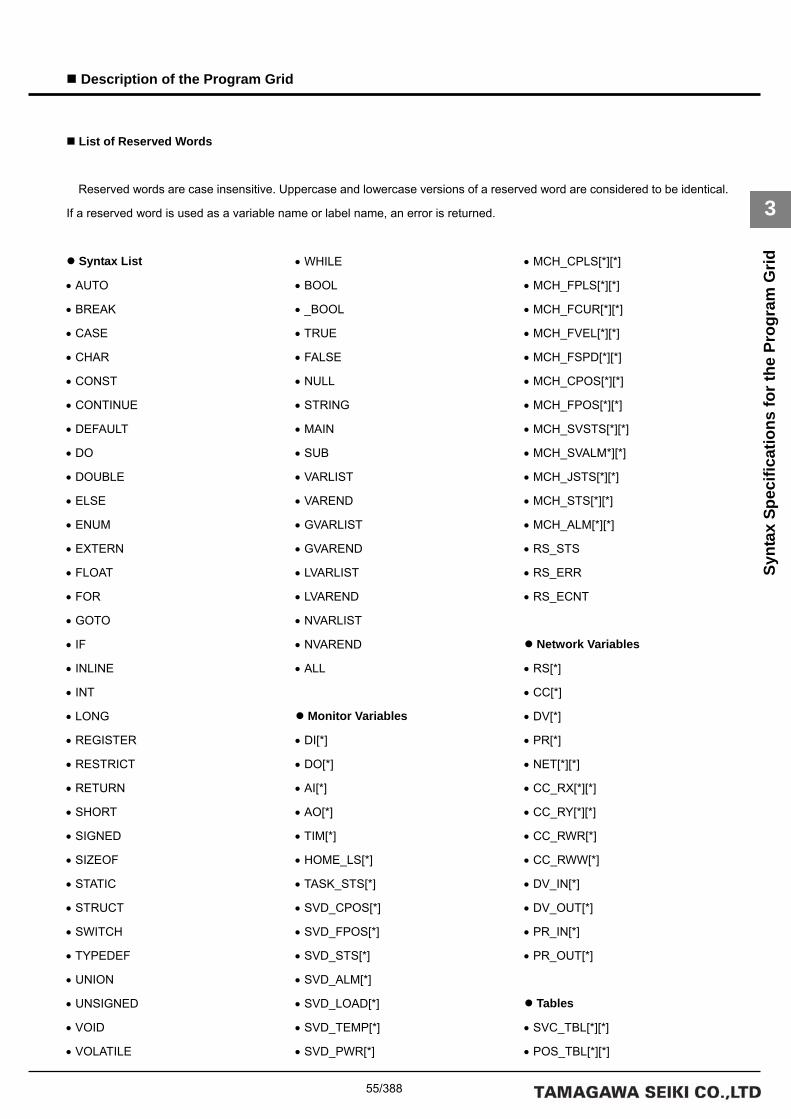
55/388
Description of the Program Grid
3
Synt
ax S
peci
ficat
ions
for t
he P
rogr
am G
rid
List of Reserved Words
Reserved words are case insensitive. Uppercase and lowercase versions of a reserved word are considered to be identical.
If a reserved word is used as a variable name or label name, an error is returned.
Syntax List
• AUTO
• BREAK
• CASE
• CHAR
• CONST
• CONTINUE
• DEFAULT
• DO
• DOUBLE
• ELSE
• ENUM
• EXTERN
• FLOAT
• FOR
• GOTO
• IF
• INLINE
• INT
• LONG
• REGISTER
• RESTRICT
• RETURN
• SHORT
• SIGNED
• SIZEOF
• STATIC
• STRUCT
• SWITCH
• TYPEDEF
• UNION
• UNSIGNED
• VOID
• VOLATILE
• WHILE
• BOOL
• _BOOL
• TRUE
• FALSE
• NULL
• STRING
• MAIN
• SUB
• VARLIST
• VAREND
• GVARLIST
• GVAREND
• LVARLIST
• LVAREND
• NVARLIST
• NVAREND
• ALL
Monitor Variables
• DI[*]
• DO[*]
• AI[*]
• AO[*]
• TIM[*]
• HOME_LS[*]
• TASK_STS[*]
• SVD_CPOS[*]
• SVD_FPOS[*]
• SVD_STS[*]
• SVD_ALM[*]
• SVD_LOAD[*]
• SVD_TEMP[*]
• SVD_PWR[*]
• MCH_CPLS[*][*]
• MCH_FPLS[*][*]
• MCH_FCUR[*][*]
• MCH_FVEL[*][*]
• MCH_FSPD[*][*]
• MCH_CPOS[*][*]
• MCH_FPOS[*][*]
• MCH_SVSTS[*][*]
• MCH_SVALM*][*]
• MCH_JSTS[*][*]
• MCH_STS[*][*]
• MCH_ALM[*][*]
• RS_STS
• RS_ERR
• RS_ECNT
Network Variables
• RS[*]
• CC[*]
• DV[*]
• PR[*]
• NET[*][*]
• CC_RX[*][*]
• CC_RY[*][*]
• CC_RWR[*]
• CC_RWW[*]
• DV_IN[*]
• DV_OUT[*]
• PR_IN[*]
• PR_OUT[*]
Tables
• SVC_TBL[*][*]
• POS_TBL[*][*]

56/388
Description of the Program Grid
3
Synt
ax S
peci
ficat
ions
for t
he P
rogr
am G
rid
• VEL_TBL[*][*]
• CUR_TBL[*][*]
• ACC_TBL[*][*]
• MTN_TBL[*][*]
Commands
• NOP
• PRMSET
• PRMREF
• VARSET
• VARREF
• ALMRST
• ALMCLR
• ACCSET
• PRMSET2
• END
• REBOOT
• CALC
• PUSH
• POP
• SALLOC
• SFREE
• SPSAV
• SPRST
• PRMGET
• MONGET
• ZPGET
• CALC2
• ID
• NOT
• NEG
• ABS
• ADD
• SUB
• MUL
• DIV
• MOD
• AND
• OR
• XOR
• ROT
• LSHT
• FIELD1
• FIELD2
• SCALE
• SIN
• COS
• MERGE
• COPY
• JUMP0
• JUMP1
• CALL
• RET
• JMP0
• JMP1
• JMP2
• JMPAND
• JMPEQ
• JMPNE
• JMPLT
• JMPGT
• JMPLE
• JMPGE
• JMPBIT
• JNPBIT
• JMPAXIS
• JMPMCH
• JMPDIO
• JNPDIO
• TASTART
• GETTID
• GETTST
• TRESTART
• TEND
• SETT
• WAITT
• TIME
• WAIT
• OUTPUT
• INPUT
• DAOUT
• ADIN
• DOUT
• DIN
• AOUT
• AIN
• BITON
• BITOFF
• BITIN
• PASSM
• DECELM
• INPOSM
• ORGM
• PASSA
• DECELA
• INPOSA
• ORGA
• SVINIT
• SVON
• SVOFF
• SVFREE
• SVPRM
• SVMODE
• SVVEL
• SVCUR
• SVPRM2
• SVSCAN
• SVEND
• HOME
• HOMESET
• HOMESET2
• HOMECLR
• HOMINGS

57/388
Description of the Program Grid
3
Synt
ax S
peci
ficat
ions
for t
he P
rogr
am G
rid
• HOMINGE
• HOMEBUMP
• HOMESV
• RUNRS
• STOPRS
• GETRS
• SETRS
• FINRS
• RUNCC
• STOPCC
• GETCC
• SETCC
• FINCC
• RUNDV
• STOPDV
• GETDV
• SETDV
• FINDV
• RUNPR
• STOPPR
• GETPR
• SETPR
• FINPR
• GETNET
• SETNET
• SETJOGJ
• JOGJ
• SETMOVAJ
• SETMOVAJT
• SETMOVAJFS
• SETMOVAJCU
• SETMOVAJTW
• SETMOVAJA1
• SETMOVAJA2
• SETMOVAJBL
• SETMOVAJBLT
• SETMOVIJ
• SETMOVIJT
• SETMOVIJFS
• SETMOVIJCU
• SETMOVIJTW
• SETMOVIJA1
• SETMOVIJA2
• SETMOVIJBL
• SETMOVIJBLT
• MOVAJ
• MOVAJT
• MOVAJFS
• MOVAJCU
• MOVAJTW
• MOVAJA1
• MOVAJA2
• MOVAJBL
• MOVAJBLT
• MOVIJ
• MOVIJT
• MOVIJFS
• MOVIJCU
• MOVIJTW
• MOVIJA1
• MOVIJA2
• MOVIJBL
• MOVIJBLT
• MOVE
• STOP
• SETOVR
• GETOVR
• SETBUF
• GETBUF
• SETWAIT
• GETWAIT
• STOPJ

58/388
Description of the Program Grid
3
Synt
ax S
peci
ficat
ions
for t
he P
rogr
am G
rid
Error Definition
An error code is represented by 3 digits. The first digit indicates the general classification for the error; the following two
digits the specific classification.
E.g. Error code 102: General classification is 1; Specific classification is 02
General classification code Description
Specific classification
code Description Error code
0 VARLIST is repeatedly defined. 100
1 VAREND is repeatedly defined. 101
2 VARLIST is not defined. 102
3 VAREND is not defined. 103
4 The order of VARLIST and VAREND is reversed. 104
10 The VARLIST definition contains 2-byte blanks. 110
11 The VARLIST definition contains invalid
characters. 111
12 The VAREND definition contains 2-byte blanks. 112
13 The VAREND definition contains invalid
characters. 113
20 2-byte blanks precede VARLIST. 120
21 Invalid characters precede VARLIST. 121
1 Variable list definition error
0 A variable definition contains 2-byte blanks. 200
1 A variable definition contains invalid characters. 201
2 A variable definition contains more characters than
the permitted maximum. 202
3 A reserved word is used for a variable definition. 203
4 A variable is repeatedly defined. 204
10 The initial value of a variable contains 2-byte
blanks. 210
11 The initial value of a variable is invalid. 211
12 The initial value of a variable is overflowing. 212
20 An array index contains 2-byte blanks. 220
21 An array index is invalid. 221
2 Variable definition error
22 The number of initial values in an array is invalid. 222

59/388
Description of the Program Grid
3
Synt
ax S
peci
ficat
ions
for t
he P
rogr
am G
rid
General classification code Description
Specific classification
code Description Error code
0 A label definition contains 2-byte blanks. 300
1 A label definition contains invalid characters. 301
2 A variable definition contains more characters than the
permitted maximum. 302
3 A reserved word is used for a label definition. 303
4 A label name is already defined as a variable name. 304
5 A label is repeatedly defined. 305
6
7
8
3 Label definition error
9
0 A command name contains 2-byte blanks. 400
1 A command name is invalid. 401
10 The number of arguments is invalid. 410
11 An argument contains 2-byte blanks. 411
12 An argument contains invalid characters. 412
13 The immediate for an argument is overflowing. 413
14 An argument contains an invalid option. 414
15 A reserved word is used as the variable name for an
argument. 415
16 The variable name for an argument is not defined. 416
20 A jump label is invalid. 420
21 An immediate is invalid. 421
22 A variable is invalid. 422
23 A variable is invalid (address reference). 423
4 Syntax error (ordinary)

60/388
Description of the Program Grid
3
Synt
ax S
peci
ficat
ions
for t
he P
rogr
am G
rid
General classification
code Description
Specific classification
code Description Error code
0 A command name contains 2-byte blanks. 500
1 A command name is invalid. 501
10 The number of arguments is invalid. 510
11 An argument contains 2-byte blanks. 511
12 An argument contains invalid characters. 512
13 The immediate for an argument is overflowing. 513
14 An argument contains an invalid option. 514
15 A reserved word is used as the variable name for an
argument. 515
16 The variable name for an argument is not defined. 516
20 A jump label is invalid. 520
21 A variable is invalid. 521
22 A variable is invalid (address reference). 522
30 More arguments than the permitted maximum are
specified. 530
31 Argument syntax error 531
32 Special argument specification error 532
33 A special argument is repeatedly defined. 533
40 Axis number specification error (with SETUP specified) 540
50 Axis number specification error (with no SETUP
specified) 550
51 More axes than the permitted maximum are specified. 551
5
Syntax error
Move instructions with special
arguments

61/388
How to Create a Program
4
Proc
edur
e fo
r Cre
atin
g a
Prog
ram
4. How to Create a Program
4.1 Procedure for Creating a Program
This section describes the procedure for creating a program with 3 orthogonal axes (X, Y, and Z) assumed.
An SVCC series target controller for which driver settings have already been completed is assumed.
Flow for Creating a Program
The flow for creating a program is described in the following flowchart.
A detailed description of each item is provided in subsequent sections.

62/388
How to Create a Program
4
Setti
ng th
e C
ontr
olle
r Par
amet
ers
4.2 Setting the SVC Parameters
Set the SVC parameters before creating the program. The parameters define the motor information, pulse rates, limit
operations, and others. Use the 【Controller Setup】 function of the SV Programmer for the setting.
*Note:
Before changing a controller parameter value, stop the program and turn the servo OFF.
• SV Programmer Controller Setup window
Like the program grid window, the initial window for parameter setting contains a tool pane in the left area and a help pane
in the bottom area. The tabs in the central area are 【System】, 【MCH】, 【I/O】, 【Task】, and 【Other】, each of which
has its own parameter setting window.
Parameter Pane
Help Pane Tool Pane

63/388
How to Create a Program
4
Setti
ng th
e C
ontr
olle
r Par
amet
ers
Tool Pane
The tool pane contains the function buttons used for the controller setup.
The buttons are grouped according to functions as shown in the following table.
*Note:
When you click the Write button, all parameters with a rewritable data ID are changed.
Make sure that all the parameters displayed in the list are correct before clicking the Write button.
Group name Button name Function
Net Search Checks the connection to the SVC.
Be sure to check the connection before setting parameters.
Read All Reads all the SVC parameters. Net Search
Write All Rewrites all the SVC parameters. *Note:
Valid only when 【All】 is selected on the Display menu.
Open Opens a parameter file.
Valid only when 【All】 is selected on the Display menu.
Save Saves the parameter file.
Valid only when 【All】 is selected on the Display menu.
Print Prints a parameter file.
Valid only when 【All】 is selected on the Display menu.
Preview Displays the print preview window.
Valid only when 【All】 is selected on the Display menu.
File
Flash Saves the parameters set to the SVC to flash memory.
DEC Displays all parameters in decimal notation.
Valid only when 【All】 is selected on the Display menu. Data
HEX Displays all parameters in hexadecimal notation.
Valid only when 【All】 is selected on the Display menu.
All Displays parameters in a list. View
Category Displays parameters by category with tabs.

64/388
How to Create a Program
4
Setti
ng th
e C
ontr
olle
r Par
amet
ers
Parameter Pane
The parameter pane is used to display parameters. The parameters can be displayed either in a list or in a categorized
form by selecting either the【All】 or 【Category】 button respectively under the Display group in the tool pane. The following
paragraphs describe the display in the parameter pane under the assumption that a check of the connection with the
controller and a read of all parameters have already been completed.
Settings on the “System Information” Tab Page
•【System】 Product information for the SV-NET controller
This page displays product information for the SVC. The information is displayed after you click the 【Net Search】 button
if the USB-connected SVC is operating normally.
Group Item Description
Hardware-ID Displays the product type of the SVC.
Software-ID Displays the software option ID.
Version Displays the software version.
Model Number Displays the model name of the product.
SV-NET Controller Information
Serial Number Displays the serial number of the product.

65/388
How to Create a Program
4
Setti
ng th
e C
ontr
olle
r Par
amet
ers
•【System】 Memory switch
This switch is used to determine the operation to be started after the SVC is powered on. You need not set any item other
than 【Auto run task number 0】. (Other items are inaccessible.)
•【System】 SV-NET baud rate
This switch is used to set the SV-NET baud rate.
*Note:
The default baud rate of the SV-NET driver is 1 Mbps. Communication is disabled if the baud rate is changed.
Ordinarily, the SVC baud rate need not be changed.
Group Item Description
Memory Switch Auto run task number 0 Automatically starts Task 0 and executes it beginning with address 0 of the
command memory after the SVC is powered on. The program must be
saved to flash memory.
Read Obtains the memory switch data. Button
Set Sets the memory switch data.

66/388
How to Create a Program
4
Setti
ng th
e C
ontr
olle
r Par
amet
ers
Settings on the “Mechanism Information” Tab Page
•【MCH】 Mechanism configuration
This page is used to set the mechanism configuration.
Group Item Description
SV-NET CH1 Sets the baud rate for SV-NET Channel 1.
The baud rate options are 250 Kbps, 500 Kbps, and 1 Mbps. The default
value is 1 Mbps.
SV-NET BAUDRATE
SV-NET CH2 Sets the baud rate for SV-NET Channel 2.
The baud rate options are 250 Kbps, 500 Kbps, and 1 Mbps. The default
value is 250 Kbps. Some SVC models do not support SV-NET Channel 2.
Read Obtains the SV-NET baud rate value. Button
Set Sets the SV-NET baud rate value.

67/388
How to Create a Program
4
Setti
ng th
e C
ontr
olle
r Par
amet
ers
Group Item Description
MCH Type Sets the mechanism type.
This parameter is fixed in accordance with the SVC type. This value
cannot be changed.
MCH Type / Max Axis
Max Axis Sets the maximum number of axes permitted to belong to the mechanism.
This parameter is fixed in accordance with the SVC type. This value
cannot be changed.
Axis Number Axis * Sets the driver axis number for an axis that belongs to the mechanism.
Note that the driver axis number is different to the MAC-ID. Under the
default setting, driver axis numbers are assigned to MAC-IDs in ascending
order and axis numbers in the mechanism are assigned to driver axis
numbers in ascending order. These settings cannot be changed.
Limit Action Sets the emergency stop limit. The default setting is 【Ignore】.
DIO Number Sets the DIO number to which the limit switch is assigned.
Emergency Limit
LS Number Sets the LS number to which the limit switch is assigned by a bit pattern.
Starting Home Mode Home Mode Sets “origin fixed” or “origin not fixed” for the servo motor position after
power-on.
Argument Check Level Level Sets the move to be performed if 0 is given as the argument for speed or
time in a move instruction. The default is to ignore this (no move is
performed or the moving axis slows down and stops).
Read Obtains the mechanism configuration information. Button
Set Sets the mechanism configuration information.

68/388
How to Create a Program
4
Setti
ng th
e C
ontr
olle
r Par
amet
ers
•【MCH】 Axis configuration
This window is used to set the configuration of each axis belonging to the mechanism.
Group Item Description
Sensor Pulse Sets the sensor resolution.
Note that the value after internal processing of the driver should be set.
Motor Type
Max Speed Sets the maximum speed value for the motor.
This parameter is used when the speed unit is 【0.01%】.
Acc・Dec Time1 Sets the acceleration/deceleration time constant in the first line. ACC/DEC
Acc・Dec Time2 Sets the acceleration/deceleration time constant in the second line.
Axis Type Sets the axis type. The options are 【Linear】, 【Rotation】, 【Linear2】,
and 【Rotation2】. The instruction units are mm for the linear-motion axis
and deg for the rotation axis.
Pulse Rate_n Sets the numerator value for the pulse rate.
Pulse Rate_d Sets the denominator value for the pulse rate.
Axis Type
Velocity Unit Sets the speed unit. The options are 【0.01%】, 【Unit/sec】, and 【rpm】.
A speed unit of 0.01% is based on the set value for 【Max Speed】 of the
motor type. If 1000 is specified for a move instruction argument when the
motor maximum speed is 5000 rpm, the rotation speed is 5000 rpm x
10.00% = 500 rpm.

69/388
How to Create a Program
4
Setti
ng th
e C
ontr
olle
r Par
amet
ers
Group Item Description
Limit Action Sets the move performed when the specified speed limit is reached. The
options are 【Ignore】, 【Smooth Stop】, 【Hard Stop】, 【Clamp】,
【Warning+Cramp】, 【Alarm+Smooth Stop】, and 【Alarm+Hard Stop】.
Speed Limit
Speed Limit Sets the speed limit value using the unit specified for the speed unit.
Infinity Reset Infinity Reset Sets the coordinate reset value for an infinite length axis. The setting is
valid if the axis type is set to infinite rotation axis or infinite linear-motion
axis.
Limit Action Sets the move performed when the specified forward direction soft limit is
reached. The options are 【Ignore】, 【Smooth Stop】, and
【Alarm+Smooth Stop】.
Positive Soft Limit
+Soft Limit Sets the forward direction soft limit value.
The default setting is 0x70000000.
Limit Action Sets the move performed when the specified reverse direction soft limit is
reached. The options are 【Ignore】, 【Smooth Stop】, and
【Alarm+Smooth Stop】.
Negative Soft Limit
-Soft Limit Sets the reverse direction soft limit value.
The default setting is 0x90000000.
Limit Action Sets the move performed when the specified forward direction stroke limit
is reached.
The options are 【Ignore】, 【Smooth Stop】, 【Hard Stop】,
【Alarm+Smooth Stop】, and 【Alarm+Hard Stop】.
DIO Number Sets the DIO number to which the forward direction stroke limit is
assigned.
Positive Hard Limit
LS Number Sets the LS number for the forward direction stroke limit by bit pattern.
Limit Action Sets the move performed when the specified reverse direction stroke limit
is reached.
The options are 【Ignore】, 【Smooth Stop】, 【Hard Stop】,
【Alarm+Smooth Stop】, and 【Alarm+Hard Stop】.
DIO Number Sets the DIO number to which the reverse direction stroke limit is
assigned.
Negative Hard Limit
LS Number Sets the LS number for the reverse direction stroke limit by bit pattern.
Read Obtains the axis configuration data. Button
Set Sets the axis configuration data.

70/388
How to Create a Program
4
Setti
ng th
e C
ontr
olle
r Par
amet
ers
Acceleration/Deceleration Time Constants
The acceleration/deceleration time constant values can be set by the ACCSET command. However, it is recommended that
the values be set in advance by parameter unless they are changed within the program. The following graph shows the
acceleration/deceleration time when acceleration/deceleration time constant values are set:
The values for acceleration/deceleration time constants 1 + 2 are set for both acceleration and deceleration.
If 0 is set to either acceleration/deceleration time constant 1 or 2, the acceleration and deceleration pattern is trapezoidal. If
acceleration/deceleration time constants 1 and 2 are equal, the S-shaped ratio is the maximum.

71/388
How to Create a Program
4
Setti
ng th
e C
ontr
olle
r Par
amet
ers
Setting Pulse Rates
The pulse rate determines the number of rotations of the motor required to move the machine the distance instructed by the
program. Set the distance (POS) to be travelled by the machine to the numerator of the SVC pulse rate and the number of
pulses (PLS) to the denominator. The following figure shows the SVC control blocks and a setting example for an actual
machine:
• If an instruction value is given:
• If feedback data is obtained:
Instruction value (POS)
Instructed pulse Driver
Instructed pulse move
Sensor Motor
Decelerator
Distance (POS)
Work
Monitor value (POS)
Feedback pulse
Feedback pulse
Driver
Sensor Motor
Decelerator
Distance (POS)
Work
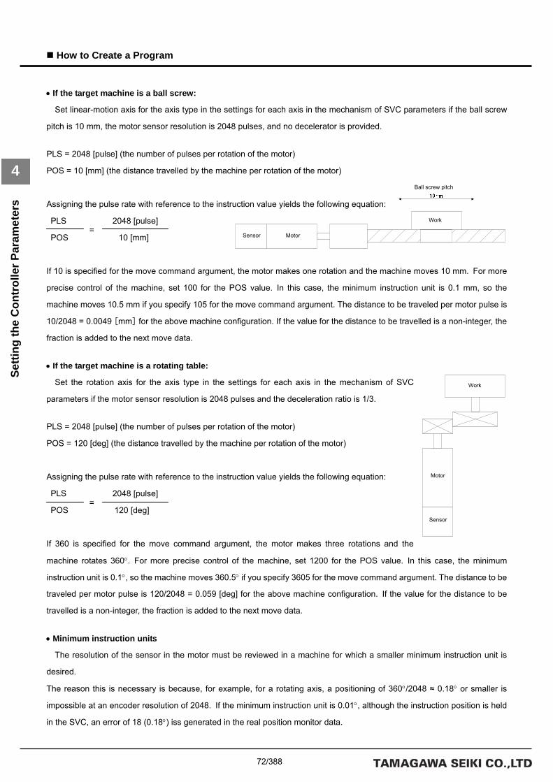
72/388
How to Create a Program
4
Setti
ng th
e C
ontr
olle
r Par
amet
ers
=
=
• If the target machine is a ball screw:
Set linear-motion axis for the axis type in the settings for each axis in the mechanism of SVC parameters if the ball screw
pitch is 10 mm, the motor sensor resolution is 2048 pulses, and no decelerator is provided.
PLS = 2048 [pulse] (the number of pulses per rotation of the motor)
POS = 10 [mm] (the distance travelled by the machine per rotation of the motor)
Assigning the pulse rate with reference to the instruction value yields the following equation:
PLS 2048 [pulse]
POS 10 [mm]
If 10 is specified for the move command argument, the motor makes one rotation and the machine moves 10 mm. For more
precise control of the machine, set 100 for the POS value. In this case, the minimum instruction unit is 0.1 mm, so the
machine moves 10.5 mm if you specify 105 for the move command argument. The distance to be traveled per motor pulse is
10/2048 = 0.0049 [mm] for the above machine configuration. If the value for the distance to be travelled is a non-integer, the
fraction is added to the next move data.
• If the target machine is a rotating table:
Set the rotation axis for the axis type in the settings for each axis in the mechanism of SVC
parameters if the motor sensor resolution is 2048 pulses and the deceleration ratio is 1/3.
PLS = 2048 [pulse] (the number of pulses per rotation of the motor)
POS = 120 [deg] (the distance travelled by the machine per rotation of the motor)
Assigning the pulse rate with reference to the instruction value yields the following equation:
PLS 2048 [pulse]
POS 120 [deg]
If 360 is specified for the move command argument, the motor makes three rotations and the
machine rotates 360°. For more precise control of the machine, set 1200 for the POS value. In this case, the minimum
instruction unit is 0.1°, so the machine moves 360.5° if you specify 3605 for the move command argument. The distance to be
traveled per motor pulse is 120/2048 = 0.059 [deg] for the above machine configuration. If the value for the distance to be
travelled is a non-integer, the fraction is added to the next move data.
• Minimum instruction units
The resolution of the sensor in the motor must be reviewed in a machine for which a smaller minimum instruction unit is
desired.
The reason this is necessary is because, for example, for a rotating axis, a positioning of 360°/2048 ≈ 0.18° or smaller is
impossible at an encoder resolution of 2048. If the minimum instruction unit is 0.01°, although the instruction position is held
in the SVC, an error of 18 (0.18°) iss generated in the real position monitor data.
Ball screw pitch
Work
Sensor Motor
Work
Motor
Sensor

73/388
How to Create a Program
4
Setti
ng th
e C
ontr
olle
r Par
amet
ers
Deceleration Stop/Immediate Stop
The following two modes are available for a machine stop during a limit operation: deceleration stop and immediate stop. In
deceleration stop mode, the machine stops after completion of data delivery from the acceleration/deceleration filter, while in
immediate stop mode, the machine stops regardless of the acceleration/deceleration filter status. The following figure shows
an example operation for each mode at the instruction values:
Speed Limit Clamp Processing
The figure below shows a move pattern for clamp processing when the speed limit is reached. The move speed is clamped
when the set speed limit is reached. The move time is extended by the clamped distance to be travelled.
Time
Set move pattern
Speed
Clamp speed
Acceleration/deceleration time constants 1 + 2
Acceleration/deceleration time constants 1 + 2

74/388
How to Create a Program
4
Setti
ng th
e C
ontr
olle
r Par
amet
ers
Infinite Length Axis
The axis can be fed indefinitely by specifying the infinite length coordinate reset parameter if Infinite rotation axis or Infinite
linear-motion axis is specified for the axis type. All move instructions except the arc interpolation instruction are valid on the
infinite length set axis. An alarm (at the task level) is returned if an arc interpolation instruction is used. Infinite length axis
must also be set for the driver if a move command is used for the infinite length axis setting. Specifically, a value of 1 must be
set to bit 7 of parameter ID 73.
Only a positive integer can be set for the infinite length coordinate reset parameter. If a negative integer is set for this
parameter, it is automatically converted to a positive integer in the SVC.
The position data assumes a ring address as shown below if the infinite length coordinate reset parameter is set for an
infinite length set axis. The following figure shows data for if the infinite length coordinate reset parameter is set to 3600.
The position data is updated in the range of 0 to 3599.

75/388
How to Create a Program
4
Setti
ng th
e C
ontr
olle
r Par
amet
ers
Settings on the “I/O Information” Tab Page
Group Item Description
Label 【A】 Sets inputs to contact A.
Clicking this label causes contacts A and B to switch.
IN
Label 【B】 Sets inputs to contact B.
Clicking this label causes contacts A and B to switch.
Label 【A】 Sets outputs to contact A.
Clicking this label causes contacts A and B to switch.
OUT
Label 【B】 Sets outputs to contact B.
Clicking this label causes contacts A and B to switch.
Read Obtains the I/O information. Button
Set Sets the I/O information.

76/388
How to Create a Program
4
Cre
atin
g th
e Pr
ogra
m
4.3 Creating the Program
This section describes the arguments of each command and the procedure for specifying commands in actual
programming. It is assumed that the SVC parameters are set to axes X, Y, and Z, as shown in the table below. All axes are
linear-motion (ball screws) and the pitch is 10 mm. Since 100 is set for the pulse rate numerator in the following example, the
minimum instruction unit is 0.1 mm.
Axis numbers in the mechanism Set group Set item Set data
Sensor resolution 2048 Motor type
Maximum speed of the motor
5000 (unit: rpm)
Acceleration/deceleration time constant 1
200 (unit: msec) Acceleration/deceleration time constant
Acceleration/deceleration time constant 2
200 (unit: msec)
Axis type Linear-motion axis
Pulse rate numerator 100
Pulse rate denominator 2048
Axis 1 (X axis)
Axis type
Speed unit 0.01%
Sensor resolution 2048 Motor type
Maximum speed of the motor
5000 (unit: rpm)
Acceleration/deceleration time constant 1
200 (unit: msec) Acceleration/deceleration time constant
Acceleration/deceleration time constant 2
200 (unit: msec)
Axis type Linear-motion axis
Pulse rate numerator 100
Pulse rate denominator 2048
Axis 2 (Y axis)
Axis type
Speed unit 0.01%
Sensor resolution 2048 Motor type
Maximum speed of the motor
5000 (unit: rpm)
Acceleration/deceleration time constant 1
200 (unit: msec) Acceleration/deceleration time constant
Acceleration/deceleration time constant 2
200 (unit: msec)
Axis type Linear-motion axis
Pulse rate numerator 100
Pulse rate denominator 2048
Axis 3 (Z axis)
Axis type
Speed unit 0.01%

77/388
How to Create a Program
4
Cre
atin
g th
e Pr
ogra
m
Servo ON Processing
Servo ON processing must be executed before the motor is started. Use the SVON command to execute servo ON
processing. A wait time of 500 ms or more is necessary after execution of the SVON command, given the period required for
the initialization of the acceleration/deceleration filter and that of the interpolation data. The SVON command argument list
and an example of SVON command settings are shown below:
• List of SVON command arguments
• Example of SVON command settings (three axes)
Argument number Argument list Description
0 MCH Specifies a mechanism number.
1 SETUP Specifies a setup axis number.
Command Argument number Argument list Argument value Description
0 MCH 0 Mechanism number 0 SVON
1 SETUP 0x0007 Setup axis number Specify Axes 1, 2, and 3.
0 TIMER 0 Timer number 0 WAIT
1 WAIT 500 Wait time 500 msec

78/388
How to Create a Program
4
Cre
atin
g th
e Pr
ogra
m
Setting the Acceleration/Deceleration Time Constants
The acceleration/deceleration time constants must be set before starting the motor, unless they have already been set in a
previous step. Set the acceleration/deceleration time constants using the ACCSET command. The ACCSET command
argument list and an example of ACCSET command settings are shown below:
• List of ACCSET command arguments
• Example of ACCSET command settings (three axes)
• Notes on the use of the ACCSET command
(A) The value of the acceleration/deceleration time constants cannot be changed while axis moving is in progress.
An alarm (at the task level) is returned if the ACCSET command is executed while axis moving is in progress.
(B) The maximum value that can be set for arguments T1 and T2 of the ACCSET command is 2000.
Use a compound move command to set greater values for T1 and T2.
(C) The ACCSET command requires a longer execution time compared with other commands. (Execution time is 4 ms with
a maximum of 8 axes for the SVCC.)
Execute this command at the beginning of the program in advance. In a system that is to be changed frequently, confirm
in advance that execution of the command will not affect other tasks.
(D) Set a value that is divisible by the interpolation period to acceleration/deceleration time constants T1 and T2. The setting
of fractions for T1 and T2 is invalid.
Argument number Argument list Description
0 MCH Specifies a mechanism number.
1 SETUP Specifies a setup axis number.
2 T1 Acceleration/deceleration time constant 1 (unit: msec)
3 T2 Acceleration/deceleration time constant 2 (unit: msec)
Command Argument number Argument list Argument value Description
0 MCH 0 Mechanism number 0
1 SETUP 0x0007 Setup axis number Specify Axes 1, 2, and 3.
2 T1 200 Acceleration/deceleration time constant 1
200 msec
ACCSET
3 T2 200 Acceleration/deceleration time constant 2
200 msec
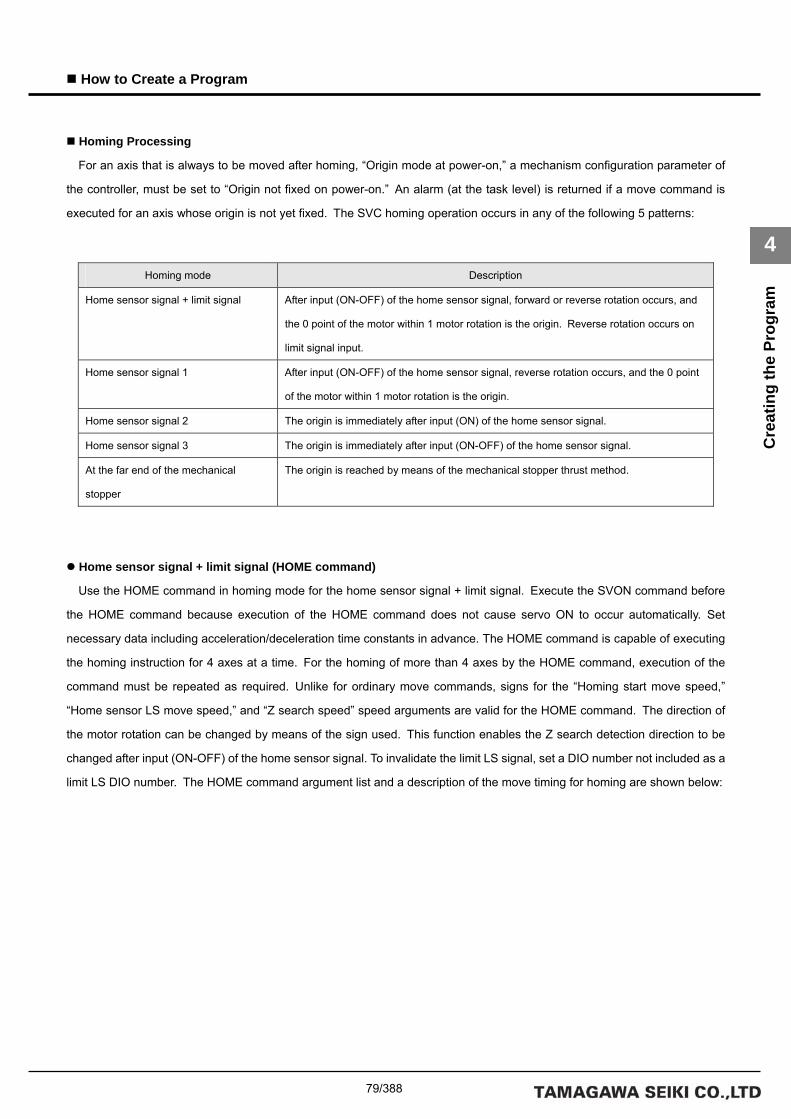
79/388
How to Create a Program
4
Cre
atin
g th
e Pr
ogra
m
Homing Processing
For an axis that is always to be moved after homing, “Origin mode at power-on,” a mechanism configuration parameter of
the controller, must be set to “Origin not fixed on power-on.” An alarm (at the task level) is returned if a move command is
executed for an axis whose origin is not yet fixed. The SVC homing operation occurs in any of the following 5 patterns:
Home sensor signal + limit signal (HOME command)
Use the HOME command in homing mode for the home sensor signal + limit signal. Execute the SVON command before
the HOME command because execution of the HOME command does not cause servo ON to occur automatically. Set
necessary data including acceleration/deceleration time constants in advance. The HOME command is capable of executing
the homing instruction for 4 axes at a time. For the homing of more than 4 axes by the HOME command, execution of the
command must be repeated as required. Unlike for ordinary move commands, signs for the “Homing start move speed,”
“Home sensor LS move speed,” and “Z search speed” speed arguments are valid for the HOME command. The direction of
the motor rotation can be changed by means of the sign used. This function enables the Z search detection direction to be
changed after input (ON-OFF) of the home sensor signal. To invalidate the limit LS signal, set a DIO number not included as a
limit LS DIO number. The HOME command argument list and a description of the move timing for homing are shown below:
Homing mode Description
Home sensor signal + limit signal After input (ON-OFF) of the home sensor signal, forward or reverse rotation occurs, and
the 0 point of the motor within 1 motor rotation is the origin. Reverse rotation occurs on
limit signal input.
Home sensor signal 1 After input (ON-OFF) of the home sensor signal, reverse rotation occurs, and the 0 point
of the motor within 1 motor rotation is the origin.
Home sensor signal 2 The origin is immediately after input (ON) of the home sensor signal.
Home sensor signal 3 The origin is immediately after input (ON-OFF) of the home sensor signal.
At the far end of the mechanical
stopper
The origin is reached by means of the mechanical stopper thrust method.

80/388
How to Create a Program
4
Cre
atin
g th
e Pr
ogra
m
• List of HOME command arguments
Argument number Argument list Description
0 MCH Specifies a mechanism number.
1 SETUP Specifies a setup axis number.
2 HS1 Homing start move speed (unit of speed)
3 MS1 Home sensor LS move speed (unit of speed)
4 ZS1 Z search speed (unit of speed)
5 HMIO1 Home sensor LS DIO number
6 HMLS1 Home sensor LS number
7 LMIO Limit LS DIO number
8 LMLS1
Axis 1 is set.
Limit LS number
9 HS2 Homing start move speed (unit of speed)
10 MS2 Home sensor LS move speed (unit of speed)
11 ZS2 Z search speed (unit of speed)
12 HMIO2 Home sensor LS DIO number
13 HMLS2 Home sensor LS number
14 LMIO2 Limit LS DIO number
15 LIM2
Axis 2 is set.
Limit LS number
16 HS3 Homing start move speed (unit of speed)
17 MS3 Home sensor LS move speed (unit of speed)
18 ZS3 Z search speed (unit of speed)
19 HMIO3 Home sensor LS DIO number
20 HMLS3 Home sensor LS number
21 LMIO3 Limit LS DIO number
22 LIM3
Axis 3 is set.
Limit LS number
23 HS4 Homing start move speed (unit of speed)
24 MS4 Home sensor LS move speed (unit of speed)
25 ZS4 Z search speed (unit of speed)
26 HMIO4 Home sensor LS DIO number
27 HMLS4 Home sensor LS number
28 LMIO4 Limit LS DIO number
29 LIM4
Axis 4 is set.
Limit LS number

81/388
How to Create a Program
4
Cre
atin
g th
e Pr
ogra
m
• Example of HOME command settings (three axes)
Argument number Argument list Argument value Description
0 MCH 0 Mechanism number 0
1 SETUP 0x0007 Setup axis number Specify Axes 1, 2, and 3.
2 HS1 1000 Homing start move speed 5000×10%=500rpm
3 MS1 200 Home sensor LS move speed 5000× 2%=100rpm
4 ZS1 100 Z search speed 5000× 1%=50rpm
5 HMIO1 0 Home sensor DIO number Specify DIO_0.
6 HMLS1 0x0001 Home sensor LS number Specify BIT_0.
7 LMIO 0 Limit DIO number Specify DIO_0.
8 LMLS1 0x8000
Axis 1 is set.
Limit LS number Specify BIT_15.
9 HS2 -1000 Homing start move speed 5000×10%=-500rpm
10 MS2 -200 Home sensor LS move speed 5000× 2%=-100rpm
11 ZS2 -100 Z search speed 5000× 1%=-50rpm
12 HMIO2 0 Home sensor DIO number Specify DIO_0.
13 HMLS2 0x0002 Home sensor LS number Specify BIT_1.
14 LMIO2 0 Limit DIO number Specify DIO_0.
15 LIM2 0x4000
Axis 2 is set.
Limit LS number Specify BIT_14.
16 HS3 1000 Homing start move speed 5000×10%=500rpm
17 MS3 200 Home sensor LS move speed 5000× 2%=100rpm
18 ZS3 -100 Z search speed 5000× 1%=-50rpm
19 HMIO3 0 Home sensor DIO number Specify DIO_0.
20 HMLS3 0x0004 Home sensor LS number Specify BIT_2.
21 LMIO3 0 Limit DIO number Specify DIO_0.
22 LIM3 0x2000
Axis 3 is set.
Limit LS number Specify BIT_13.
23 HS4 0
24 MS4 0
25 ZS4 0
26 HMIO4 0
27 HMLS4 0
28 LMIO4 0
29 LIM4 0
Axis 4 is set.

82/388
How to Create a Program
4
Cre
atin
g th
e Pr
ogra
m
• Move timing for the HOME command (Normal move)
*Note 1:
Servo ON processing (SVON command + simple wait time) must be executed before the HOME command.
*Note 2:
The origin position may fluctuate if the home sensor signal goes OFF too close to the motor 0 point.
In such an event, the motor 0 point or the home sensor signal position must be adjusted.
*Note 3:
Use the HOME2 command for a motor that has 2 motor 0 points. (E.g. TBL-V motor containing resolver 2X type)
When the HOME command is used, the origin position may shift 180° according to the position in 1 rotation of the motor
after power is turned on.
Description of move timing:
1. Homing starts.
2. Moves at the homing start move speed until the home sensor signal goes ON.
3. The home sensor signal goes ON.
4. Moves at the home sensor LS move speed until the home sensor signal goes OFF.
5. The home sensor signal goes OFF.
6. Moves at the Z search speed to the motor 0 point in 1 rotation of the motor.

83/388
How to Create a Program
4
Cre
atin
g th
e Pr
ogra
m
• Move timing for the HOME command (if the limit LS signal goes ON before the home sensor signal)
Description of move timing:
1. Homing starts.
2. Moves at the homing start move speed until the home sensor signal goes ON.
3. The limit LS signal goes ON before the home sensor signal.
4. Reverses at the homing start move speed and moves until the limit LS signal goes OFF.
5. Moves at the homing start move speed until the home sensor signal goes ON.
6. Reverses at the homing start move speed when the home sensor signal goes OFF and moves until the home sensor signal
goes ON.
7. The home sensor signal goes ON.
8. Moves at the home sensor LS move speed until the home sensor signal goes OFF.
9. The home sensor signal goes OFF.
10. Moves at the Z search speed to the motor 0 point in 1 rotation of the motor.
Home sensor signal
Motor 0 point
Homing start move speed
Home sensor LS move speed
Z search speed
ON OFF
Limit LS signal ONOFF
Homing start move speed
Homing start position
OFF
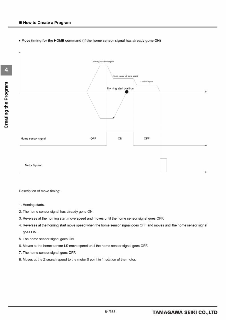
84/388
How to Create a Program
4
Cre
atin
g th
e Pr
ogra
m
• Move timing for the HOME command (if the home sensor signal has already gone ON)
Description of move timing:
1. Homing starts.
2. The home sensor signal has already gone ON.
3. Reverses at the homing start move speed and moves until the home sensor signal goes OFF.
4. Reverses at the homing start move speed when the home sensor signal goes OFF and moves until the home sensor signal
goes ON.
5. The home sensor signal goes ON.
6. Moves at the home sensor LS move speed until the home sensor signal goes OFF.
7. The home sensor signal goes OFF.
8. Moves at the Z search speed to the motor 0 point in 1 rotation of the motor.
Home sensor signal
Motor 0 point
Home sensor LS move speed
Z search speed
ON OFFOFF
Homing start position
Homing start move speed

85/388
How to Create a Program
4
Cre
atin
g th
e Pr
ogra
m
Home sensor signals 1, 2, and 3 (HOMESV command)
Use the HOMESV command in homing mode for the home sensor signals 1, 2, and 3. The HOMESV command is capable
of executing the homing instruction for 4 axes at a time. For the homing of more than 4 axes by the HOMESV command,
execution of the command must be repeated as required. Unlike the HOME command, the HOMESV command sets
parameters in the driver so that the driver itself will return to the origin. Servo ON processing is executed automatically. The
SVC sends the home sensor signal to the driver. The HOMESV command argument list and a description of the move timing
for homing are shown below.

86/388
How to Create a Program
4
Cre
atin
g th
e Pr
ogra
m
• List of HOMESV command arguments
Argument number Argument list Description
0 MCH Specifies a mechanism number.
1 SETUP Specifies a setup axis number.
2 TYP1 Homing Type
3 PRE1 Preset value (pulses)
4 DIR1 Homing direction 0: Forward (CW) 1: Reverse (CCW)
5 VEL1 Homing speed (rpm)
6 CRP1 Creep speed (rpm)
7 HMIO1 DIO number
8 HMLS1
Axis 1 is set.
Origin LS number
9 TYP2 Homing Type
10 PRE2 Preset value (pulses)
11 DIR2 Homing direction 0: Forward (CW) 1: Reverse (CCW)
12 VEL2 Homing speed (rpm)
13 CRP2 Creep speed (rpm)
14 HMIO2 DIO number
15 HMLS2
Axis 2 is set.
Origin LS number
16 TYP3 Homing Type
17 PRE3 Preset value (pulses)
18 DIR3 Homing direction 0: Forward (CW) 1: Reverse (CCW)
19 VEL3 Homing speed (rpm)
20 CRP3 Creep speed (rpm)
21 HMIO3 DIO number
22 HMLS3
Axis 3 is set.
Origin LS number
23 TYP4 Homing Type
24 PRE4 Preset value (pulses)
25 DIR4 Homing direction 0: Forward (CW) 1: Reverse (CCW)
26 VEL4 Homing speed (rpm)
27 CRP4 Creep speed (rpm)
28 HMIO4 DIO number
29 HMLS4
Axis 4 is set.
Origin LS number

87/388
How to Create a Program
4
Cre
atin
g th
e Pr
ogra
m
• Example of HOMESV command settings (three axes)
Argument number Argument list Argument value Description
0 MCH 0 Mechanism number 0
1 SETUP 0x0007 Setup axis number Specify Axes 1, 2, and 3.
2 TYP1 0 HOMESV type Home sensor signal 1
3 PRE1 0 Preset value 0
4 DIR1 0 Homing direction Forward
5 VEL1 500 Homing start move speed 500rpm
6 CRP1 50 Creep speed 50rpm
7 HMIO1 0 Home sensor DIO number Specify DIO_0.
8 HMLS1 0x0001
Axis 1
Home sensor LS number Specify BIT_0.
9 TYP2 2 HOMESV type Home sensor signal 2
10 PRE2 0 Preset value 0
11 DIR2 0 Homing direction Forward
12 VEL2 500 Homing start move speed 500 rpm
13 CRP2 50 Creep speed 50 rpm
14 HMIO2 0 Home sensor DIO number Specify DIO_0.
15 HMLS2 0x0002
Axis 2
Home sensor LS number Specify BIT_1.
16 TYP3 3 HOMESV type Home sensor signal 3
17 PRE3 0 Preset value 0
18 DIR3 0 Homing direction Forward
19 VEL3 500 Homing start move speed 500 rpm
20 CRP3 50 Creep speed 50 rpm
21 HMIO3 0 Home sensor DIO number Specify DIO_0.
22 HMLS3 0x0004
Axis 3
Home sensor LS number Specify BIT_2.
23 TYP4 0
24 PRE4 0
25 DIR4 0
26 VEL4 0
27 CRP4 0
28 HMIO4 0
29 HMLS4 0
Axis 4

88/388
How to Create a Program
4
Cre
atin
g th
e Pr
ogra
m
• Move timing for the HOMESV command (home sensor signal 1)
*Note 1:
Servo ON processing (SVON command + simple wait time) must be executed before the HOMESV command.
*Note 2:
The origin position may fluctuate if the home sensor signal goes ON too close to the motor 0 point.
In such an event, the motor 0 point or the home sensor signal position must be adjusted.
Description of move timing:
1. Homing starts.
2. The home sensor signal goes ON.
3. Reverses at the creep speed and moves to the motor 0 point in 1 rotation of the motor.

89/388
How to Create a Program
4
Cre
atin
g th
e Pr
ogra
m
• Move timing for the HOMESV command (home sensor signal 2)
Description of move timing:
1. Homing starts.
2. Moves at the homing start move speed until the home sensor signal goes ON.
3. The home sensor signal goes ON. (The origin is fixed at this position.)
4. Reverses at the creep speed and moves to the position at which the origin fixed.
Home sensor signal
Homing start move speed
ON OFFOFF
Homing start position
Creep speed

90/388
How to Create a Program
4
Cre
atin
g th
e Pr
ogra
m
• Move timing for the HOMESV command (home sensor signal 3)
Description of move timing:
1. Homing starts.
2. Moves at the homing start move speed until the home sensor signal goes ON.
3. The home sensor signal goes ON.
4. Reverses at the creep speed and moves until the home sensor signal goes OFF.
* The sign is enabled for creep speed for this step. Reverses rotation is performed if the sign is the same as that for the
homing start move speed, and forward rotation is performed if it differs.
5. The home sensor signal goes OFF. (The origin is fixed at this position.)
6. Reverses at the creep speed and moves to the position at which the origin fixed.
Home sensor signal
Homing start move speed
ON OFFOFF
Homing start position
Creep speed

91/388
How to Create a Program
4
Cre
atin
g th
e Pr
ogra
m
Mechanical stopper thrust method (HOMEBUMP command)
Use the HOMEBUMP command in homing mode for the mechanical stopper thrust method. The HOMEBUMP command is
capable of executing the homing instruction for 5 axes at a time. For the homing of more than 5 axes by the HOMEBUMP
command, execution of the command must be repeated as required. Unlike the HOME command, the HOMEBUMP
command sets parameters in the driver so that the driver itself will return to the origin. The HOMEBUMP command argument
list and a description of the move timing for homing are shown below.
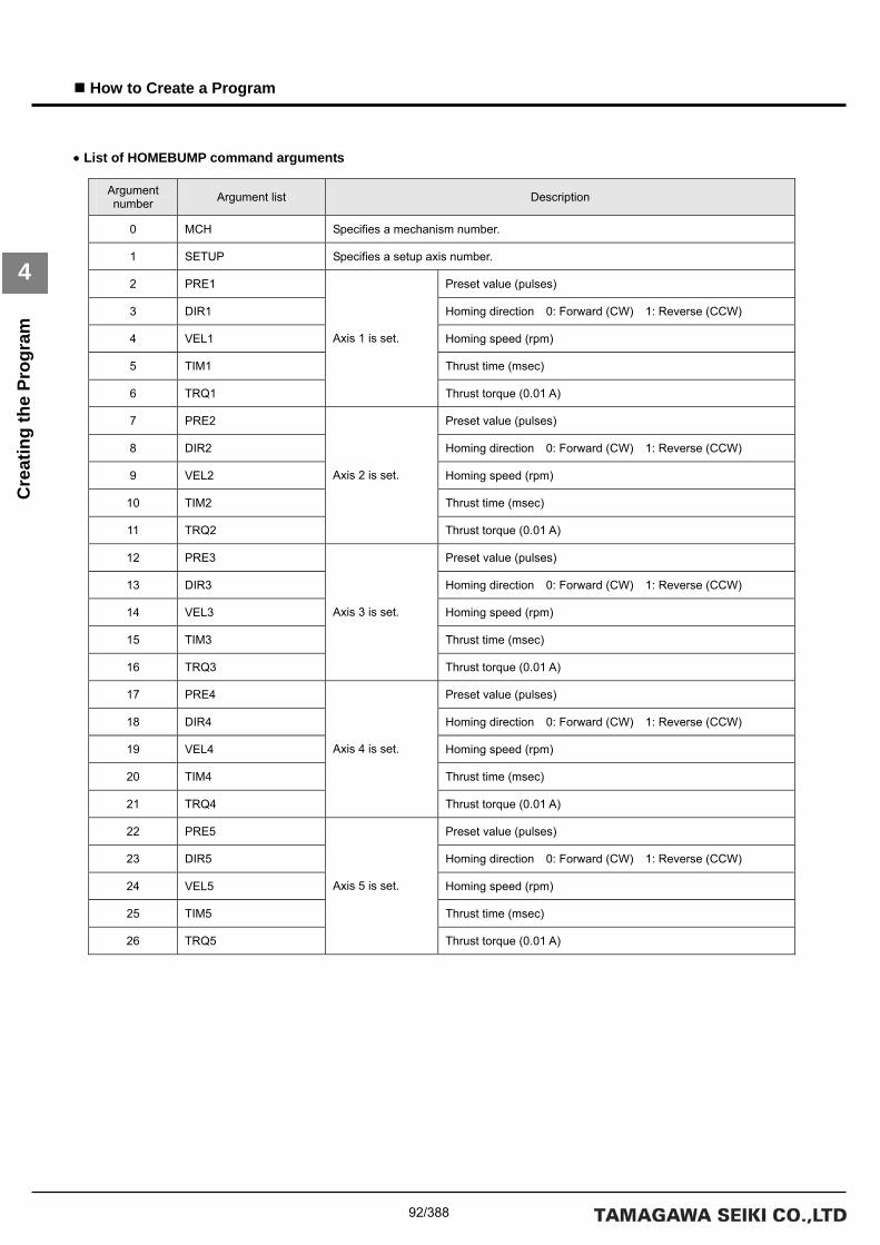
92/388
How to Create a Program
4
Cre
atin
g th
e Pr
ogra
m
• List of HOMEBUMP command arguments
Argument number Argument list Description
0 MCH Specifies a mechanism number.
1 SETUP Specifies a setup axis number.
2 PRE1 Preset value (pulses)
3 DIR1 Homing direction 0: Forward (CW) 1: Reverse (CCW)
4 VEL1 Homing speed (rpm)
5 TIM1 Thrust time (msec)
6 TRQ1
Axis 1 is set.
Thrust torque (0.01 A)
7 PRE2 Preset value (pulses)
8 DIR2 Homing direction 0: Forward (CW) 1: Reverse (CCW)
9 VEL2 Homing speed (rpm)
10 TIM2 Thrust time (msec)
11 TRQ2
Axis 2 is set.
Thrust torque (0.01 A)
12 PRE3 Preset value (pulses)
13 DIR3 Homing direction 0: Forward (CW) 1: Reverse (CCW)
14 VEL3 Homing speed (rpm)
15 TIM3 Thrust time (msec)
16 TRQ3
Axis 3 is set.
Thrust torque (0.01 A)
17 PRE4 Preset value (pulses)
18 DIR4 Homing direction 0: Forward (CW) 1: Reverse (CCW)
19 VEL4 Homing speed (rpm)
20 TIM4 Thrust time (msec)
21 TRQ4
Axis 4 is set.
Thrust torque (0.01 A)
22 PRE5 Preset value (pulses)
23 DIR5 Homing direction 0: Forward (CW) 1: Reverse (CCW)
24 VEL5 Homing speed (rpm)
25 TIM5 Thrust time (msec)
26 TRQ5
Axis 5 is set.
Thrust torque (0.01 A)

93/388
How to Create a Program
4
Cre
atin
g th
e Pr
ogra
m
• Example of HOMEBUMP command settings (three axes)
Argument number Argument list Argument value Description
0 MCH 0 Mechanism number 0
1 SETUP 0x0007 Setup axis number Specify Axes 1, 2, and 3 in the mechanism.
2 PRE1 0 Preset value 0
3 DIR1 0 Homing direction Forward
4 VEL1 500 Homing start move speed 500rpm
5 TIM1 500 Thrust time 500 msec
6 TRQ1 100
Axis 1
Thrust torque 1.0 A
7 PRE2 0 Preset value 0
8 DIR2 1 Homing direction Reverse
9 VEL2 500 Homing start move speed 500 rpm
10 TIM2 500 Thrust time 500 msec
11 TRQ2 100
Axis 2
Thrust torque 1.0 A
12 PRE3 0 Preset value 0
13 DIR3 0 Homing direction Forward
14 VEL3 500 Homing start move speed 500 rpm
15 TIM3 500 Thrust time 500 msec
16 TRQ3 50
Axis 3
Thrust torque 0.5 A
17 PRE4 0
18 DIR4 0
19 VEL4 0
20 TIM4 0
21 TRQ4 0
Axis 4
22 PRE5 0
23 DIR5 0
24 VEL5 0
25 TIM5 0
26 TRQ5 0
Axis 5

94/388
How to Create a Program
4
Cre
atin
g th
e Pr
ogra
m
• Move timing for the HOMEBUMP command
*Note 1:
Servo ON processing (SVON command + simple wait time) must be executed before the HOMEBUMP command.
*Note 2:
With the HOMEBUMP command, servo OFF is executed after completion of homing. Execute servo ON again for
continued operation.
Description of move timing:
1. Homing starts.
2. The axis moves until it comes into contact with the mechanical stopper.
3. The origin is fixed when the thrust torque and the thrust time reach or exceed their respective set values.
4. Servo OFF is executed after the origin is fixed.

95/388
How to Create a Program
4
Cre
atin
g th
e Pr
ogra
m
Move Instructions
The following is an actual example of axes being moved by an individual-axis absolute position move instruction (MOVAJ
command). In the move pattern for this example, the X axis is moved by 500.0 mm, the Y axis by 500.0 mm, and the Z axis by
250.0 mm from the current position (0, 0, 0) at a speed of 1000 rpm. Specify in advance the initial values for the positions and
speeds to variables that are set as arguments for the move instructions. Examples of variable definitions, the MOVAJ
command argument list, and examples of argument settings are shown below.
Example of a MOVAJ command move

96/388
How to Create a Program
4
Cre
atin
g th
e Pr
ogra
m
• List of variable definitions
Specify the position and move speed of each axis as the initial values of variables for use in the program.
Use of variables makes later program changes easier.
Argument number Variable name Initial value Description
0 X_POS_0 0 Axis 1 (X axis), position 0
1 X_POS_5000 5000 Axis 1 (X axis), position 5000
2 Y_POS_0 0 Axis 2 (Y axis), position 0
3 Y_POS_5000 5000 Axis 2 (Y axis), position 5000
4 Z_POS_0 0 Axis 3 (Z axis), position 0
5 Z_POS_2500 2500 Axis 3 (Z axis), position 2500
6
7 X_VEL_0 0 Axis 1 (X axis), speed 0
8 X_VEL_2000 2000 Axis 1 (X axis), speed 2000
9 Y_VEL_0 0 Axis 2 (Y axis), speed 0
10 Y_VEL_2000 2000 Axis 2 (Y axis), speed 2000
11 Z_VEL_0 0 Axis 3 (Z axis), speed 0
12 Z_VEL_2000 2000 Axis 3 (Z axis), speed 2000

97/388
How to Create a Program
4
Cre
atin
g th
e Pr
ogra
m
• List of MOVAJ command arguments
Argument number Argument list Description
0 MCH Specifies a mechanism number.
1 SETUP Specifies a setup axis number.
2 P1 Target position
3 V1 Axis 1 is set.
Target speed
4 P2 Target position
5 V2 Axis 2 is set.
Target speed
6 P3 Target position
7 V3 Axis 3 is set.
Target speed
8 P4 Target position
9 V4 Axis 4 is set.
Target speed
10 P5 Target position
11 V5 Axis 5 is set.
Target speed
12 P6 Target position
13 V6 Axis 6 is set.
Target speed
14 P7 Target position
15 V7 Axis 7 is set.
Target speed
16 P8 Target position
17 V8 Axis 8 is set.
Target speed
18 P9 Target position
19 V9 Axis 9 is set.
Target speed
20 P10 Target position
21 V10 Axis 10 is set.
Target speed
22 P11 Target position
23 V11 Axis 11 is set.
Target speed
24 P12 Target position
25 V12 Axis 12 is set.
Target speed
26 P13 Target position
27 V13 Axis 13 is set.
Target speed
28 P14 Target position
29 V14 Axis 14 is set.
Target speed

98/388
How to Create a Program
4
Cre
atin
g th
e Pr
ogra
m
• Example of MOVAJ command settings (three axes)
Argument number Argument list Argument value Description
0 MCH 0 Mechanism number 0
1 SETUP 0x0007 Setup axis number Specify Axes 1, 2, and 3.
2 P1 X_POS_5000 Target position 500.0 mm
3 V1 X_VEL_2000 Axis 1 is set.
Target speed 1000 rpm 5000×0.2
4 P2 Y_POS_5000 Target position 500.0 mm
5 V2 Y_VEL_2000 Axis 2 is set.
Target speed 1000 rpm 5000×0.2
6 P3 Z_POS_2500 Target position 250.0 mm
7 V3 Z_VEL_2000 Axis 3 is set.
Target speed 1000 rpm 5000×0.2
8 P4 0
9 V4 0 Axis 4 is set.
10 P5 0
11 V5 0 Axis 5 is set.
12 P6 0
13 V6 0 Axis 6 is set.
14 P7 0
15 V7 0 Axis 7 is set.
16 P8 0
17 V8 0 Axis 8 is set.
18 P9 0
19 V9 0 Axis 9 is set.
20 P10 0
21 V10 0 Axis 10 is set.
22 P11 0
23 V11 0 Axis 11 is set.
24 P12 0
25 V12 0 Axis 12 is set.
26 P13 0
27 V13 0 Axis 13 is set.
28 P14 0
29 V14 0 Axis 14 is set.

99/388
How to Create a Program
4
Cre
atin
g th
e Pr
ogra
m
Move patterns of the 3 axes
As described in “Move Instructions” in Section 2 “Outline of Commands,” the SVC adjusts the move speeds for each axis
specified in the setup axis number of the move instruction to the speed of the axis with the latest arrival time so that all 3 axes
arrive at the specified targets simultaneously. The following figure shows an actual move pattern set using the MOVAJ
command:
Description of move pattern:
Convert the speeds of the X, Y, and Z axes to the instruction unit, then:
Instruction unit speed (mm/sec) = move speed (1000 rpm) ÷ 60 × pulse rate (10.0 mm) = 167 (mm/sec)
The arrival time (t) for X and Y axes with the same move distance is:
Arrival time (t) = move distance (500.0 mm) ÷ instruction unit speed (167 mm/sec) = 3 sec + acceleration/deceleration time
constant
The arrival time (t) for the Z axis is:
Arrival time (t) = move distance (250.0 mm) ÷ instruction unit speed (167 mm/sec) = 1.5 sec + acceleration/deceleration time
constant
Therefore, the 3 axes arrive at the target position simultaneously if the move speed of the Z axis is halved (83 mm/sec).
The compound speed (F) of each axis is:
Compound speed (F) = 222 speed axis Z speed axis Y speed axis X ++ = 250 mm/sec
The move speed of the Z axis is 83 mm/sec.

100/388
How to Create a Program
4
Cre
atin
g th
e Pr
ogra
m
Creating a Go-and-Return Program
In the first part of this section a description of how axes are moved to a particular target position was provided, and in the
remaining part of this section a description is provided of the commands required to return these axes to the origin, which
enables repeat execution of moves.
PASS instruction (INPOSM command)
The INPOSM command of the PASS instruction sets a wait at the current index if axis moving is in progress for all axes
belonging to the mechanism. Use this command when a succeeding command is to be executed after a wait for the
in-position following completion of axis moving. The INPOSM command argument list and an example of INPOSM command
settings are shown below:
• List of INPOSM command arguments
• Example of INPOSM command settings
The setting of the INPOSM command consists of setting the target mechanism number to MCH only. An alarm (at the task
level) is returned if a mechanism number that does not exist is set.
Argument number Argument list Description
0 MCH Specifies a mechanism number.
Argument number Argument list Argument value Description
0 MCH 0 Mechanism number 0

101/388
How to Create a Program
4
Cre
atin
g th
e Pr
ogra
m
Timer instruction (WAIT command)
The WAIT command of a timer instruction executes a simple wait. The WAIT command argument list and an example of
WAIT command settings are shown below:
• List of WAIT command arguments
• Example of WAIT command settings
Branch instruction (JMP0 command)
The JMP0 command of the branch instruction causes an unconditional branch to the specified label. The JMP0 command
argument list and an example of JMP0 command settings are shown below:
• List of JMP0 command arguments
• Example of JMP0 command settings
Enter a predefined label name as the branch destination label. For definitions of label names, refer to Section 3.2 “Syntax
Specifications for the Program Grid.”
Argument number Argument list Description
0 TIMER Specifies a timer number.
1 WAIT Specifies a wait time. (Unit: msec)
Argument number Argument list Argument value Description
0 TIMER 0 Timer number 0
1 WAIT 1000 Wait time 1000 msec
Argument number Argument list Description
0 LABEL Branch destination label
Argument number Argument list Argument value Description
0 LABEL L1 Branch destination label L1

102/388
How to Create a Program
4
Cre
atin
g th
e Pr
ogra
m
Example go-and-return program
The table below shows an example command list for a go-and-return program. Commands (HOME and MOVAJ) with many
arguments are listed only for axes specified in the setup axis number.
==============================Continues on next page.==============================
Label Command Argument number Argument list Argument
value Description
0 MCH 0 Mechanism number 0 SVON
1 SETUP 0x0007 Setup axis number Specify Axes 1, 2, and 3.
0 TIMER 0 Timer number 0 WAIT
1 WAIT 500 Wait time 500 msec
0 MCH 0 Mechanism number 0
1 SETUP 0x0007 Setup axis number Specify Axes 1, 2, and 3.
2 T1 200 Acceleration/deceleration time constant 1 200 ms
ACCSET
3 T2 200 Acceleration/deceleration time constant 2 200 ms
0 MCH 0 Mechanism number 0
1 SETUP 0x0007 Setup axis number Specify Axes 1, 2, and 3.
2 HS1 1000 Homing start move speed 5000×10% = 500 rpm
3 MS1 200 Home sensor LS move speed 5000×2% = 100 rpm
4 ZS1 100 Z search speed 5000×1% = 50 rpm
5 HMIO1 0 Home sensor DIO number Specify DIO_0.
6 HMLS1 0x0001 Home sensor LS number Specify BIT_0.
7 LMIO 0 Limit DIO number Specify DIO_0.
8 LMLS1 0x8000
Axis 1 is set.
Limit LS number Specify BIT_15.
9 HS2 -1000 Homing start move speed 5000×10% = -500 rpm
10 MS2 -200 Home sensor LS move speed 5000×2% = -100 rpm
11 ZS2 -100 Z search speed 5000×1% = -50 rpm
12 HMIO2 0 Home sensor DIO number Specify DIO_0.
13 HMLS2 0x0002 Home sensor LS number Specify BIT_1.
14 LMIO2 0 Limit DIO number Specify DIO_0.
15 LIM2 0x4000
Axis 2 is set.
Limit LS number Specify BIT_14.
16 HS3 1000 Homing start move speed 5000×10% = 500 rpm
17 MS3 200 Home sensor LS move speed 5000×2% = 100 rpm
18 ZS3 -100 Z search speed 5000×1% = -50 rpm
19 HMIO3 0 Home sensor DIO number Specify DIO_0.
20 HMLS3 0x0004 Home sensor LS number Specify BIT_2.
21 LMIO3 0 Limit DIO number Specify DIO_0.
HOME
22 LIM3 0x2000
Axis 3 is set.
Limit LS number Specify BIT_13.
ORGM 0 MCH 0 Mechanism number 0

103/388
How to Create a Program
4
Cre
atin
g th
e Pr
ogra
m
==============================Continued from previous page.==============================
Label Command Argument number Argument list Argument value Description
0 MCH 0 Mechanism number 0
1 SETUP 0x0007 Setup axis number Specify Axes 1, 2, and 3.
2 P1 X_POS_5000 Target position 500.0 mm
3 V1 X_VEL_2000 Axis 1 is set.
Target speed 1000 rpm 5000×0.2
4 P2 Y_POS_5000 Target position 500.0 mm
5 V2 Y_VEL_2000 Axis 2 is set.
Target speed 1000 rpm 5000×0.2
6 P3 Z_POS_2500 Target position 250.0 mm
L1 MOVAJ
7 V3 Z_VEL_2000 Axis 3 is set.
Target speed 1000 rpm 5000×0.2
INPOSM 0 MCH 0 Mechanism number 0
0 TIMER 0 Timer number 0 WAIT
1 WAIT 1000 Wait time 1000 msec
0 MCH 0 Mechanism number 0
1 SETUP 0x0007 Setup axis number Specify Axes 1, 2, and 3.
2 P1 X_POS_0 Target position 0.0 mm
3 V1 X_VEL_2000 Axis 1 is set.
Target speed 1000 rpm 5000×0.2
4 P2 Y_POS_0 Target position 0.0 mm
5 V2 Y_VEL_2000 Axis 2 is set.
Target speed 1000 rpm 5000×0.2
6 P3 Z_POS_0 Target position 0.0 mm
MOVAJ
7 V3 Z_VEL_2000 Axis 3 is set.
Target speed 1000 rpm 5000×0.2
INPOSM 0 MCH 0 Mechanism number 0
0 TIMER 0 Timer number 0 WAIT
1 WAIT 500 Wait time 1000 msec
JMP0 0 LABEL L1 Branch destination label L1

104/388
How to Create a Program
4
Exec
utin
g th
e Pr
ogra
m
4.4 Executing the Program
Once creation of the program has been completed, build and download the program and then execute it. Use the 【Build】,
【Down load】, and 【Start】 buttons under the 【Build】 group in the program grid tool pane. The following window is
displayed after the building step has been completed for the created program.

105/388
How to Create a Program
4
Exec
utin
g th
e Pr
ogra
m
Building Successful
The message “Building Successful” is displayed in the output pane on successful completion of a build operation.
Other messages and a description of their meanings are as follows:
• Program Step Number Indicates the number of steps in the created program.
*Note:
The number of steps does not always match the number of lines on the program grid.
• Program Memory Size Indicates the size of the command memory being used.
• Variable Memory Size Indicates the size of the variable memory being used.
The currently displayed program is automatically overwritten to the existing program and saved when build is executed. For a
newly created program, the file save dialog box is displayed. Save the current program before executing build.

106/388
How to Create a Program
4
Exec
utin
g th
e Pr
ogra
m
Building Failed
Try executing build with the name of label 【L1】 changed to 【1L】.
The error information pane is activated and outputs detailed error information. To go to the location of a particular error,
double click the relevant error information line. The output pane reads as follows when an error occurs:
Detailed error information, including the number of errors that occurred, is output. The program is overwritten and saved even
if building failed.

107/388
How to Create a Program
4
Exec
utin
g th
e Pr
ogra
m
Downloading
When the 【Down load】 button is clicked, the program is built and the object file (executable file) is then downloaded to the
SVC main unit. The following message is output on successful completion of a download:
The 【F6】 function key can also be used for downloading. Combining use of 【F6】 and 【F5】 (program execution) simplifies
operation of the program grid.
Program Execution
Click the 【Start】 button to execute the program. The program starts Task 0 and the command memory is executed
sequentially beginning with address 0. Click the 【Stop】 button to stop program execution.
The 【F5】 function key can also be used for program execution. To stop execution of the program, press 【SHIFT+F5】.
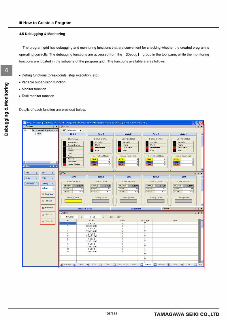
108/388
How to Create a Program
4
Deb
uggi
ng &
Mon
itorin
g
4.5 Debugging & Monitoring
The program grid has debugging and monitoring functions that are convenient for checking whether the created program is
operating correctly. The debugging functions are accessed from the 【Debug】 group in the tool pane, while the monitoring
functions are located in the subpane of the program grid. The functions available are as follows:
• Debug functions (breakpoints, step execution, etc.)
• Variable supervision function
• Monitor function
• Task monitor function
Details of each function are provided below:

109/388
How to Create a Program
4
Deb
uggi
ng &
Mon
itorin
g
Debugging Functions
The debugging functions can be used after the program has been downloaded. To switch from normal mode to debug
mode, select 【Debug】 from the combo list under the 【Debug】 group in the tool pane. The 【F12】 function key can also
be used to switch between normal mode and debug mode. In debug mode, the 【Task View】, 【Break】, and 【Release】
buttons can be used.
Each debug mode function is described below.
• Trace
When the 【Task View】 button is clicked in debug mode, the currently executed index for each task is highlighted. When
this is done, the background colors of the program step grid change. The 【F8】 function key can also be used for trace
display. The following table shows the preset background color for each task:
Task No. Background color
0 Yellow
1 Silver
2 Silver
3 Silver
4 Silver
5 Silver
6 Silver
7 Silver

110/388
How to Create a Program
4
Deb
uggi
ng &
Mon
itorin
g
• Setting and resetting breakpoints
Breakpoints can be set in the program step grid. To set a breakpoint, select the line in the program step grid on which a
breakpoint is to be set and click the 【Break】 button. To reset the breakpoint, select the line on which the breakpoint is to be
reset and click the 【Release】 button. The 【F9】 function key can also be used for setting and resetting breakpoints. If a
breakpoint has not yet been set on the selected line, pressing 【F9】 sets one on that line. If a breakpoint has already been
set on the selected line, pressing 【F9】resets it. The background of a line on which a breakpoint has been set is highlighted
pink. When a breakpoint is hit, the background of that line is highlighted brown.
Breakpoints are valid only in Task 0. If any other task executes a breakpoint, the operation is not recognized. Make sure that
breakpoints are only set to indexes that are executed by Task 0.
A maximum of 20 breakpoints can be set. Note, however, that no breakpoint can be set on the first line of the program.
• Restarting
The 【ReStart】 button can be used when the program stops at a breakpoint. Clicking the 【Start】 button after the program
stops at a breakpoint restarts execution at the first address of the command memory. To debug the remainder, click the
【ReStart】 button rather than the 【Start】 button. The same operation can be performed by clicking the 【F5】 function key
after the program stops at a breakpoint. If the function key is clicked in any other status of the program, execution starts at the
beginning of the command memory.
• Step-in
The 【Step In】 button can be used while the program is stopped at a breakpoint and the task trace display is valid. Clicking
the 【Step In】 button step-executes the program. The 【F11】 function key can also be used for step execution. Clicking the
key in any other status of the program has no effect.

111/388
How to Create a Program
4
Deb
uggi
ng &
Mon
itorin
g
Variable Monitor Function
The program monitor function enables you to monitor the values of defined variables during program execution. This
function is valid only if the program has been downloaded normally. The following is a description of this function.
The pane to the right is an example of how previously set program variables are
monitored.
The pane below is the monitor pane that is displayed after the program has been
downloaded and executed.
It indicates initial values assigned to the variable name fields defined in the
variable list.

112/388
How to Create a Program
4
Deb
uggi
ng &
Mon
itorin
g
Monitor Function
Information about the SVC, driver, and I/O can be monitored regardless of whether or not the program is being executed.
The monitoring windows are shown below. Use the monitor function to check if each axis is moving according to the program
you created.
For details on the monitor function, refer to the description of “Monitor Pane” in “Subpane” of Section 3.1 “Edit Function of the
Program Grid.”
Task Monitor Function
The task monitor function can be used after the program has been downloaded. This function enables you to monitor the
execution status of each task and the values of stack pointers. For details on the task monitor function, refer to the description
of “Task Pane” in “Subpane” of Section 3.1 “Edit Function of the Program Grid.”

113/388
How to Create a Program
4
Savi
ng th
e Pr
ogra
m
4.6 Saving the Program
Save the created program to flash memory if it works correctly. For automatic execution after power-on, set 【Auto run task
number 0】 of the 【Memory Switch】 of the SVC to ON before saving the program to flash memory. Program creation
completes if automatic execution is confirmed when the power is turned on again after the settings for saving the program
have been completed.
Saving a Program to Flash Memory
Save the created program to flash memory. Save the entire command memory area of SRAM to the command memory
area (save area) of flash memory. The saved command memory area is copied to SRAM for use on the next startup. To save
the command memory, click the 【Flash】 button under the 【File】 group in the tool pane.
Saving to flash memory is disabled during program execution. A warning message is displayed if you click the 【Flash】
button during program execution. If you stop the program in the message dialog window, the command memory is saved to
flash memory after the program stops. You cannot operate SV Programmer during a save operation. A window indicating that
a save operation is in progress is displayed.
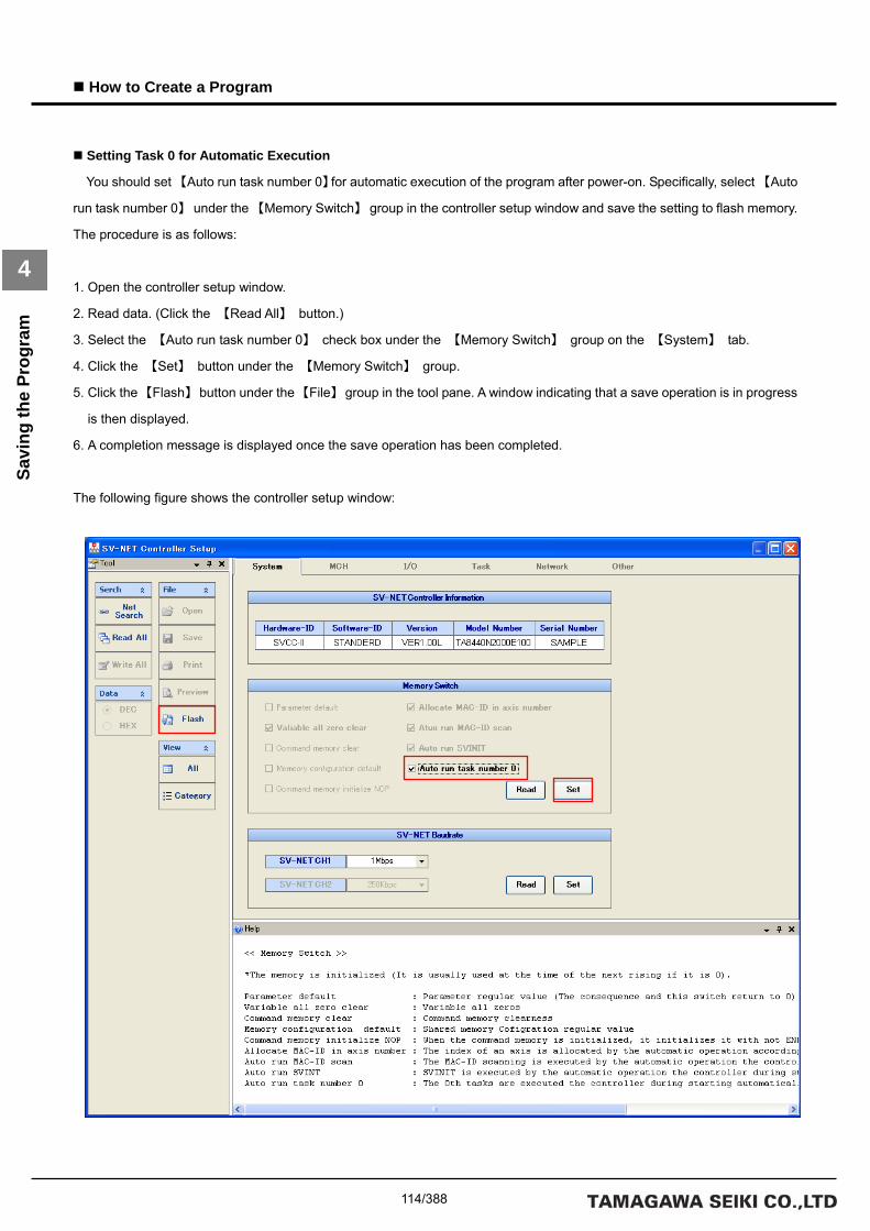
114/388
How to Create a Program
4
Savi
ng th
e Pr
ogra
m
Setting Task 0 for Automatic Execution
You should set 【Auto run task number 0】for automatic execution of the program after power-on. Specifically, select 【Auto
run task number 0】 under the 【Memory Switch】 group in the controller setup window and save the setting to flash memory.
The procedure is as follows:
1. Open the controller setup window.
2. Read data. (Click the 【Read All】 button.)
3. Select the 【Auto run task number 0】 check box under the 【Memory Switch】 group on the 【System】 tab.
4. Click the 【Set】 button under the 【Memory Switch】 group.
5. Click the 【Flash】 button under the 【File】 group in the tool pane. A window indicating that a save operation is in progress
is then displayed.
6. A completion message is displayed once the save operation has been completed.
The following figure shows the controller setup window:

115/388
Program Applications
5
Prog
ram
App
licat
ions
5. Program Applications
This section describes example applications for convenient functions and move instructions implemented in TMasM. The
mechanism used for the program described in this section employs the same 3-axes configuration with the same parameter
settings for each axis as described in the preceding section. The following is a list of the parameter settings:
• Parameter settings for each axis in the mechanism
Axis numbers in the mechanism Set group Set item Set data
Sensor resolution 2048 Motor type
Maximum speed of the motor 5000 (unit: rpm)
Acceleration/deceleration time constant 1 200 (unit: msec) Acceleration/decelerati
on time constant
Acceleration/deceleration time constant 2 200 (unit: msec)
Axis type Linear-motion axis
Pulse rate numerator 100
Pulse rate denominator 2048
Axis 1 (X axis)
Axis type
Speed unit 0.01%
Sensor resolution 2048 Motor type
Maximum speed of the motor 5000 (unit: rpm)
Acceleration/deceleration time constant 1 200 (unit: msec) Acceleration/decelerati
on time constant
Acceleration/deceleration time constant 2 200 (unit: msec)
Axis type Linear-motion axis
Pulse rate numerator 100
Pulse rate denominator 2048
Axis 2 (Y axis)
Axis type
Speed unit 0.01%
Sensor resolution 2048 Motor type
Maximum speed of the motor 5000 (unit: rpm)
Acceleration/deceleration time constant 1 200 (unit: msec) Acceleration/decelerati
on time constant
Acceleration/deceleration time constant 2 200 (unit: msec)
Axis type Linear-motion axis
Pulse rate numerator 100
Pulse rate denominator 2048
Axis 3 (Z axis)
Axis type
Speed unit 0.01%

116/388
How to Create a Program
5
Indi
rect
Var
iabl
e R
efer
ence
5.1 Indirect Variable Reference
The efficiency of programs can be improved by using indirect references to variables. This applies, for example, to cases
where move instructions with different argument values are used for a mechanism that repeats the same pattern for
movement of the axes. Let us create a program with a virtual machine in mind.
Virtual Machine
The following is a configuration diagram for the virtual machine. In the diagram, the X and Z axes are orthogonal to each
other and produce linear-motion. Let us assume that the X axis is the first axis in the mechanism and the Z axis is the third.

117/388
Program Applications
5
Indi
rect
Var
iabl
e R
efer
ence
Program Specifications for the Virtual Machine
The program for the virtual machine repeats the operation of pressing a work against the tool mounted on the Z axis 5
times, once for each of works (1) through (5) in sequence. Note that the axes complete the move to the start position after
homing. The start position is Work (1) center, 15.00 mm behind the tool center, as shown in the configuration diagram for the
virtual machine.
Program that Uses Immediates for Move Instruction Arguments
The table below is a program list that gives immediates to move instruction arguments. Each of the 5 repetitions is counted
by the variable CNT specified in the branch instruction. The press operation against the tool is repeated until the 5th work is
reached. Homing processing and servo on processing are omitted from the program list.
• Program list
==============================Continues on next page.==============================
Label Command Argument number Argument list Argument value Description
0 MCH 0 Mechanism number 0
1 SETUP 0x0001 Setup axis number Specify Axis 1.
2 P1 150 Target distance 15.0 mm
L1 MOVIJ
3 V1 1000 Axis 1 is set.
Target speed 500 rpm
INPOSM 0 MCH 0 Mechanism number 0
0 MCH 0 Mechanism number 0
1 SETUP 0x0004 Setup axis number Specify Axis 3.
2 P1 50 Target distance 50.0 mm
MOVIJ
3 V1 1000 Axis 1 is set.
Target speed 500 rpm
INPOSM 0 MCH 0 Mechanism number 0
0 MCH 0 Mechanism number 0
1 SETUP 0x0004 Setup axis number Specify Axis 3.
2 P1 -50 Target distance -50.0 mm
MOVIJ
3 V1 1000 Axis 1 is set.
Target speed 500 rpm
INPOSM 0 MCH 0 Mechanism number 0
: : : : Omitted.
: : : : Omitted.
0 MCH 0 Mechanism number 0
1 SETUP 0x0001 Setup axis number Specify Axis 1.
2 P1 -1000 Target distance -100.0 mm
MOVIJ
3 V1 1000 Axis 1 is set.
Target speed 500 rpm
INPOSM 0 MCH 0 Mechanism number 0

118/388
How to Create a Program
5
Indi
rect
Var
iabl
e R
efer
ence
==============================Continued from previous page.==============================
Although in-between move instructions are omitted, this example shows that moves for works (1) to (5) need to be coded if
immediates are given to arguments. With an increase in the number of works, however, the number of move instructions to be
coded increases accordingly, thus decreasing programming efficiency. Even if variables are given to arguments of move
instructions, a subroutine to determine the number of the work currently being processed is required, so greater effort is
required compared with the program, described on the next page, that uses indirect variable reference.
Label Command Argument number Argument list Argument value Description
0 VAR CNT Variable CNT = CNT + 1
1 OP1 CNT Operand 1 Variable CNT
ADD
2 OP2 1 Operand 2 Immediate 1
0 LABEL L2 Branch destination label Goes to L2 if CNT>=5.
1 OP1 CNT Operand 1 Variable CNT
JMPGE
2 OP2 5 Operand 2 Immediate 5
JMP0 0 LABEL L1 Branch destination label Goes to L1 unconditionally.
L2 END End of program

119/388
Program Applications
5
Indi
rect
Var
iabl
e R
efer
ence
Program that Uses Indirect Variable References for Move Instruction Arguments
This subsection describes an example of a program that uses indirect variable references for move instruction arguments.
The tables below are a variable list and a program list for this example. Some variables are array type.
• List of variable definitions
• Program list
==============================Continues on next page.==============================
Variable number Variable name Initial value Description
0 CNT 0 Counter to count the number of repetitions up to 5
1 X_ARR[5] 150, 200, 200, 300, 150 Array to store the distance for the X-axis move
2 PTR 0 Variable for indirect reference
3 PCNT 0 Counter for indirect references
Label Command Argument number Argument list Argument value Description
0 VAR PTR Initialize variable PTR by the address of X_ARR[0].L1 ID
1 OP1 &X_ARR[0] Operand 1 Address of X_ARR[0].
0 VAR PCNT Variable PCNT = 0 ID
1 OP1 0 Operand 1 Initialize variable PCNT by immediate 0.
0 MCH 0 Mechanism number 0
1 SETUP 0x0001 Setup axis number Specify Axis 1.
2 P1 *PTR Reference variable PTR indirectly for the target distance.
L2 MOVIJ
3 V1 1000 Axis 1 is set.
Target speed 500 rpm
INPOSM 0 MCH 0 Mechanism number 0
0 MCH 0 Mechanism number 0
1 SETUP 0x0004 Setup axis number Specify Axis 3.
2 P1 50 Target distance 50 mm
MOVIJ
3 V1 1000 Axis 1 is set.
Target speed 500 rpm
INPOSM 0 MCH 0 Mechanism number 0
0 MCH 0 Mechanism number 0
1 SETUP 0x0004 Setup axis number Specify Axis 3.
2 P1 -50 Target distance -50 mm
MOVIJ
3 V1 1000 Axis 1 is set.
Target speed 500 rpm
INPOSM 0 MCH 0 Mechanism number 0

120/388
How to Create a Program
5
Indi
rect
Var
iabl
e R
efer
ence
==============================Continued from previous page.==============================
Since this virtual machine program uses indirect variable references, it completes with the program list shown above. This
program can be created in a shorter time than the program using immediates and its size is reduced. Even if more works are
used, the program size remains unchanged. These works can be processed only by changing the size of the array to which
the move data for the X axis is saved and changing the count statement in the conditional branch instruction. The program
using immediates for move instruction arguments requires additional effort in that if the distance to be travelled by the X axis
is changed, for example, the arguments of each move instruction must be changed accordingly. If the distance is defined by a
variable, this change can easily be addressed by simply changing the initial value of the variable. It is recommended that
variables be used for data (including move instruction arguments, acceleration/deceleration time constants, wait time values,
and speed override values) that is to be changed during program debugging or that may be changed if the configuration of
the machine is changed.
Label Command Argument number Argument list Argument value Description
0 VAR PTR Variable PTR = PTR + 1 (Add 1 to the address of variable X_ARR[*].)
1 OP1 PTR Operand 1 Variable PTR
ADD
2 OP2 1 Operand 2 Immediate 1
0 VAR PCNT Variable PCNT = PCNT + 1
1 OP1 PCNT Operand 1 Variable PCNT
ADD
2 OP2 1 Operand 2 Immediate 1
0 LABEL L3 Branch destination label Goes to L3 if PCNT>=5.
1 OP1 PCNT Operand 1 Variable PCNT
JMPGE
2 OP2 5 Operand 2 Immediate 5
JMP0 0 LABEL L2 Branch destination label Goes to L2 unconditionally.
0 MCH 0 Mechanism number 0
1 SETUP 0x0001 Setup axis number Specify Axis 1.
2 P1 -1000 Target distance -100.0 mm
L3 MOVIJ
3 V1 1000 Axis 1 is set.
Target speed 500 rpm
INPOSM 0 MCH 0 Mechanism number 0
0 VAR CNT Variable CNT = CNT + 1
1 OP1 CNT Operand 1 Variable CNT
ADD
2 OP2 1 Operand 2 Immediate 1
0 LABEL L4 Branch destination label Goes to L4 if CNT>=5.
1 OP1 CNT Operand 1 Variable CNT
JMPGE
2 OP2 5 Operand 2 Immediate 5
JMP0 0 LABEL L1 Branch destination label Goes to L1 unconditionally.
L4 END End of program

121/388
Program Applications
5
Mon
itor I
nstr
uctio
ns a
nd M
onito
r Var
iabl
es
5.2 Monitor Instructions and Monitor Variables
The monitor instruction (MONGET command) and monitor variables are available so as to allow the program to access the
internal data of the SVC and drivers. The monitor instruction enables the program to branch according to the state of each
axis or to share the monitor data with external devices. For the argument list of the monitor instruction, refer to “Data
Acquisition Instructions” in Section 2.2 “Data Instructions.” Refer to “List of Monitor Items” in each of the SVC Users’
Manuals for lists of monitor items that can be referenced. For monitor variables, refer to “List of Monitor Variables” in Section
3.2 “Syntax Specifications for the Program Grid.”
Actual Electric Current Supervisory Program
This subsection describes an example of a program that uses a monitor variable to cause a branch if the actual electric
current value of an axis reaches a predetermined decision value. Using this function can minimize the chances of collision for
a system in which there is a risk of machines colliding. Homing processing and servo on processing are omitted from the
program list.
• Program list
==============================Continues on next page.==============================
Label Command Argument number Argument list Argument value Description
0 MCH 0 Mechanism number 0
1 SETUP 0x0001 Setup axis number Specify Axis 1.
2 P1 10000 Target position 1,000 mm
L1 MOVAJ
3 V1 200 Axis 1 is set.
Target speed 100 rpm
0 LABEL M1 Branch destination label Goes to branch destination label M1 if the actual electric current reaches 1.0 A.
1 OP1 SVD_FCUR[0] Operand 1 Monitor variable Actual electric current of SVD Axis 1
L2 JMPGE
2 OP2 100 Operand 2 Immediate 100
0 LABEL L2 Branch destination label L2
1 MCH 0 Mechanism number 0
JMPMCH
2 PASS 4 PASS point The condition is satisfied if the axis is moving.

122/388
How to Create a Program
5
Mon
itor I
nstr
uctio
ns a
nd M
onito
r Var
iabl
es
==============================Continued from previous page.==============================
This program list causes a reverse move when the actual electric current of SVD Axis 1 reaches plus or minus 1.0 A.
Label Command Argument number Argument list Argument value Description
0 MCH 0 Mechanism number 0
1 SETUP 0x0001 Setup axis number Specify Axis 1.
2 P1 0 Target position 0mm
L3 MOVAJ
3 V1 200 Axis 1 is set.
Target speed 100 rpm
0 LABEL M2 Branch destination label Goes to branch destination label M2 if the actual electric current reaches -1.0 A.
1 OP1 SVD_FCUR[0] Operand 1 Monitor variable Actual electric current of SVD Axis 1
L4 JMPLE
2 OP2 -100 Operand 2 Immediate -100
0 LABEL L4 Branch destination label L4
1 MCH 0 Mechanism number 0
JMPMCH
2 PASS 4 PASS point The condition is satisfied if the axis is moving.
JMP0 0 LABEL L1 Branch destination label Goes to L1 unconditionally.
0 MCH 0 Mechanism number 0
1 SETUP 0x0001 Setup axis number Specify Axis 1.
2 P1 0 Target position 0 mm
M1 MOVAJ
3 V1 200 Axis 1 is set.
Target speed 100 rpm
INPOSM 0 MCH 0 Mechanism number 0
0 TIMER 0 Timer number 0 WAIT
1 WAIT 500 Wait time 500 msec
JMP0 0 LABEL L1 Branch destination label Goes to L1 unconditionally.
0 MCH 0 Mechanism number 0
1 SETUP 0x0001 Setup axis number Specify Axis 1.
2 P1 10000 Target position 1,000 mm
M2 MOVAJ
3 V1 200 Axis 1 is set.
Target speed 100 rpm
INPOSM 0 MCH 0 Mechanism number 0
0 TIMER 0 Timer number 0 WAIT
1 WAIT 500 Wait time 500 msec
JMP0 0 LABEL L2 Branch destination label Goes to L2 unconditionally.

123/388
Program Applications
5
Mon
itor I
nstr
uctio
ns a
nd M
onito
r Var
iabl
es
Actual Position Supervisory Program
This subsection describes an example of a program that uses a monitor variable to cause a branch if the present actual
position of an axis reaches a predetermined decision value. This function is useful for systems that need a branch to be
caused based on the present position. Homing processing and servo on processing are omitted from the program list.
• Program list
This program list causes the following operation: When the actual position of the axis moved by JOG (constant-speed
continuous feed) reaches 500.0 mm, the MOVAJ command (individual-axis absolute position move instruction) moves the
axis to the 1000.0 mm position.
Label Command Argument number Argument list Argument value Description
0 MCH 0 Mechanism number 0
1 SETUP 0x0001 Setup axis number Specify Axis 1.
JOGJ
2 V1 1000 Axis 1 is set. Target speed 500 rpm
0 LABEL M1 Branch destination label Goes to branch destination label M1 if the actual position reaches 500.0 mm.
1 OP1 MCH_FPOS[0][0] Operand 1 Monitor variable Actual position of Axis 1 of Mechanism 1 (instruction unit)
L1 JMPGE
2 OP2 5000 Operand 2 Immediate 5000
JMP0 0 LABEL L1 Branch destination label Goes to L1 unconditionally.
0 MCH 0 Mechanism number 0
1 SETUP 0x0001 Setup axis number Specify Axis 1.
2 P1 10000 Target position 1,000.0 mm
M1 MOVAJ
3 V1 5000 Axis 1 is set.
Target speed 2500 rpm
INPOSM 0 MCH 0 Mechanism number 0
END End of program
Speed
Time
2000rpm
500rpm
JOG command
MOVAJ command
Distance: 500 mm Distance: 500 mm

124/388
How to Create a Program
5
Com
poun
d M
ove
Com
man
ds
5.3 Compound Move Commands
The primary speed type MOVAJFS/MOVIJFS command, the secondary speed type MOVAJCU/MOVIJCU command, and
the tertiary speed type MOVAJBL/MOVIJBL command are used to create compound move commands. To use a compound
move command, set as short a time as possible to the acceleration/deceleration filter. Note also that correct values must be
specified for the initial speed argument and end speed argument for proper operation of the compound command. If smooth
axis motion is not obtained, review the values of the initial speed and end speed arguments in the program.
To use compound move commands, insert either a PASSM or PASSA command of the PASS instruction in between each
move instruction to connect the move commands. When moving all the axes belonging to a mechanism by compound move
commands, use the PASSM command. When moving each axis by compound move commands, use the PASSA command.
If a compound move is performed for each axis but other axes are not going to move, the PASSM command can be used.
Tertiary Speed Type (Acceleration) + 2-Stage Deceleration by Primary Speed Type (Deceleration)
The table below is a program list for a program that uses the tertiary speed type MOVIJBL command for acceleration and
the primary speed type MOVIJFS command for deceleration. Homing processing and servo on processing are omitted from
the program list.
• Program list
==============================Continues on next page.==============================
Label Command Argument number Argument list Argument value Description
0 MCH 0 Mechanism number 0
1 SETUP 0x0007 Setup axis number Specify Axes 1, 2, and 3.
2 T1 8 Acceleration/deceleration time constant 1 8msec
ACCSET
3 T2 8 Acceleration/deceleration time constant 2 8msec
0 MCH 0 Mechanism number 0
1 SETUP 0x0001 Setup axis number Specify Axis 1.
2 P1 1000 Target distance 100.0 mm
3 S1 0 Start point speed 0 rpm
4 E1 4000 End point speed 2000 rpm
5 A1 0 Start point acceleration 0
MOVIJBL
6 B1 0
Axis 1 is set.
End point acceleration 0
0 MCH 0 Mechanism number 0 PASSA
1 SETUP 0x0001 Setup axis number Specify Axis 1.
0 MCH 0 Mechanism number 0
1 SETUP 0x0001 Setup axis number Specify Axis 1.
2 P1 3000 Target distance 300.0 mm
MOVIJ
3 V1 4000 Axis 1 is set.
Target speed 2000 rpm
0 MCH 0 Mechanism number 0 PASSA
1 SETUP 0x0001 Setup axis number Specify Axis 1.

125/388
Program Applications
5
Com
poun
d M
ove
Com
man
ds
==============================Continued from previous page.==============================
The figure below shows the move pattern of this program.
Note that the user can program any compound move pattern.
Label Command Argument number Argument list Argument value Description
0 MCH 0 Mechanism number 0
1 SETUP 0x0001 Setup axis number Specify Axis 1.
2 P1 800 Target distance 80.0 mm
3 S1 4000 Start point speed 4000 rpm
MOVIJFS
4 E1 500
Axis 1 is set.
End point speed 250 rpm
0 MCH 0 Mechanism number 0 PASSA
1 SETUP 0x0001 Setup axis number Specify Axis 1.
0 MCH 0 Mechanism number 0
1 SETUP 0x0001 Setup axis number Specify Axis 1.
2 P1 200 Target distance 20.0 mm
3 S1 500 Start point speed 250 rpm
MOVIJFS
4 E1 0
Axis 1 is set.
End point speed 0 rpm
0 MCH 0 Mechanism number 0 INPOSA
1 SETUP 0x0001 Setup axis number Specify Axis 1.
END End of program

126/388
How to Create a Program
5
Arc
Inte
rpol
atio
n In
stru
ctio
n
5.4 Arc Interpolation Instruction
Arc interpolation is possible with the right angle arc interpolation individual axis move instruction (MOVIJA1/MOVAJA1
command) and the arc interpolation individual axis move instruction (MOVIJA2/MOVAJA2 command). Helical move is also
enabled if you specify a synchronous axis. To execute arc interpolation, set as short a time as possible to the
acceleration/deceleration filter.
Right Angle Arc Interpolation Individual Axis Move
Create a program that performs a move of 100.0 mm in radius and a rotation of 90° using the right angle arc interpolation
individual axis move instruction (MOVIJA1 command). The correct target position must be given to make the arc a perfect
circle. The correct center coordinates can be determined by giving the correct target position. Homing processing and servo
on processing are omitted from the program list.
• Program list
This program list gives a move pattern for an arc
interpolation move of 90° around the center at 100.0 mm on
the X axis and 100.0 mm on the Y axis, from the present
position.
The right angle arc interpolation move instruction is available
for 90° arc moves only.
Label Command Argument number Argument list Argument value Description
0 MCH 0 Mechanism number 0
1 SETUP 0x0003 Setup axis number Specify Axes 1 and 2.
2 T1 8 Acceleration/deceleration time constant 1 8 msec
ACCSET
3 T2 8 Acceleration/deceleration time constant 2 8 msec
0 MCH 0 Mechanism number 0
1 SETUP 0x0003 Setup axis number Specify Axes 1 and 2.
2 P1 1000 Target distance 100.0 mm
3 V1 1000 Target speed 500 rpm
4 M1 1
Axis 1 is set.
Mode 1: Set for the X axis.
5 P2 1000 Target distance 100.0 mm
6 V2 1000 Target speed 500 rpm
MOVIJA1
7 M2 -1
Axis 2 is set.
Mode -1: Set for the Y axis.
PASSM 0 MCH 0 Mechanism number 0
END End of program

127/388
Program Applications
5
Arc
Inte
rpol
atio
n In
stru
ctio
n
Center Specified Arc Interpolation Individual Axis Move
Create a program that performs a move of 100.0 mm in radius and a rotation of 360° using the center specified mode of the
arc interpolation individual axis move instruction (MOVIJA2 command). The correct coordinates for the center must be given
to make the arc a perfect circle. In the center specified mode, you can set arc angles of up to 360°. No rotation angle greater
than this can be specified. Homing processing and servo on processing are omitted from the program list.
• Program list
The figure on the right shows the move pattern for this
program list. One rotation (360°) is made with a radius of
100.0 mm.
Label Command Argument number Argument list Argument value Description
0 MCH 0 Mechanism number 0
1 SETUP 0x0003 Setup axis number Specify Axes 1 and 2.
2 T1 8 Acceleration/deceleration time constant 1 8 msec
ACCSET
3 T2 8 Acceleration/deceleration time constant 2 8 msec
0 MCH 0 Mechanism number 0
1 SETUP 0x0003 Setup axis number Specify Axes 1 and 2.
2 P1 0 Target distance 0 mm
3 V1 1000 Target speed 500 rpm
4 M1 2 Mode 2: Set for the X axis with the center and CW rotation specified.
5 O1 1000
Axis 1 is set.
Center specification X axis: 100.0 mm
6 P2 0 Target distance 0 mm
7 V2 1000 Target speed 500 rpm
8 M2 -1 Mode -1: Set for the Y axis.
MOVIJA2
9 O2 0
Axis 2 is set.
Center specification Y axis: 0 mm
INPOSM 0 MCH 0 Mechanism number 0
END End of program

128/388
How to Create a Program
5
Arc
Inte
rpol
atio
n In
stru
ctio
n
Angle Specified Arc Interpolation Individual Axis Move (Multi-circumference Program)
Create a program that performs a move of 100.0 mm in radius and 3 rotations of the rotation angle (1080°) + 1/4 rotation of
the rotation angle (90°) using the angle specified mode of the arc interpolation individual axis move instruction (MOVIJA2
command). As with the center specified mode, the correct target positions for the X and Y axes, the start point angle, and end
point angle must be given to make the arc a perfect circle. In the angle specified mode, you cannot use the same setting for
both the start position and the end position. If the same setting is used, only a linear interpolation move for a synchronous
axis is performed. A linear interpolation move is performed on the X and Y axes if the difference between the start point angle
and the end point angle is a multiple of 180°. Homing processing and servo on processing are omitted from the program list.
• Program list
The figure on the right shows the move pattern for this
program list. Three rotations (1080°) + 1/4 rotation (90°)
are made with a radius of 100.0 mm.
Label Command Argument number Argument list Argument value Description
0 MCH 0 Mechanism number 0
1 SETUP 0x0003 Setup axis number Specify Axes 1 and 2.
2 T1 8 Acceleration/deceleration time constant 1 8 msec
ACCSET
3 T2 8 Acceleration/deceleration time constant 2 8 msec
0 MCH 0 Mechanism number 0
1 SETUP 0x0003 Setup axis number Specify Axes 1 and 2.
2 P1 1000 Target distance 100.0 mm
3 V1 1000 Target speed 500 rpm
4 M1 1 Mode 1: Set for the X axis with angle specified.
5 O1 0
Axis 1 is set.
Start point angle of the X axis: 0.000°
6 P2 1000 Target distance 100.0 mm
7 V2 1000 Target speed 500 rpm
8 M2 -1 Mode -1: Set for the Y axis.
MOVIJA2
9 O2 1170000
Axis 2 is set.
End point angle of the Y axis: 1080.000° + 90.000°
INPOSM 0 MCH 0 Mechanism number 0
END End of program
Center
Present position
Y axis
X axis

129/388
Program Applications
5
Arc
Inte
rpol
atio
n In
stru
ctio
n
Angle Specified Arc Interpolation Individual Axis Move (Start Point Angle, End Point Angle)
Create a program that performs a move from the start point angle of 45° to the end point angle of 135° using the angle
specified mode of the arc interpolation individual axis move instruction (MOVIJA2 command). This subsection describes the
method for specifying the start point angle and the end point angle for the angel specified arc interpolation move. Homing
processing and servo on processing are omitted from the program list.
• Program list
Label Command Argument number Argument list Argument value Description
0 MCH 0 Mechanism number 0
1 SETUP 0x0003 Setup axis number Specify Axes 1 and 2.
2 T1 8 Acceleration/deceleration time constant 1 8 msec
ACCSET
3 T2 8 Acceleration/deceleration time constant 2 8 msec
0 MCH 0 Mechanism number 0
1 SETUP 0x0003 Setup axis number Specify Axes 1 and 2.
2 P1 1000 Target distance 100.0 mm
3 V1 1000 Target speed 500 rpm
4 M1 1 Mode 1: Set for the X axis with angle specified.
5 O1 45000
Axis 1 is set.
Start point angle of the X axis: 45,000°
6 P2 0 Target distance 0.0 mm
7 V2 1000 Target speed 500 rpm
8 M2 -1 Mode -1: Set for the Y axis.
MOVIJA2
9 O2 135000
Axis 2 is set.
End point angle of the Y axis: 135.000°
INPOSM 0 MCH 0 Mechanism number 0
END End of program

130/388
How to Create a Program
5
Arc
Inte
rpol
atio
n In
stru
ctio
n
The figure below shows the move pattern of this program list. Determine the center based on the start point angle, end
point angle, and the target position.
A clockwise (CW) rotation is made if the start point angle is less than the end point angle.
The following figure shows the move pattern if the end point angle in the program list is set to -225000 (-225°).
A counterclockwise (CCW) rotation is made if the start point angle is greater than the end point angle.

131/388
Program Applications
5
Arc
Inte
rpol
atio
n In
stru
ctio
n
For a counterclockwise (CCW) shift changing the present center point, set the start point angle to -45000 (-45°) and the end
point angle to -135000 (-135°). A counterclockwise (CCW) rotation is made if the start point angle is greater than the end point
angle. The following figure shows the move pattern.

132/388
How to Create a Program
5
Arc
Inte
rpol
atio
n In
stru
ctio
n
Helical Move
Program helical moves using the center specified arc interpolation individual axis move instruction (MOVAJA2) and the
PASS instruction. The specifications for the helical move program are as follows:
Arc interpolation radius: 100.0 mm
Rotation angle: 5 rotations
Z axis shift: 10.0 mm per rotation of the rotation angle Homing processing and servo on processing are omitted from the
program list.
• Program list
Label Command Argument number Argument list Argument value Description
0 MCH 0 Mechanism number 0
1 SETUP 0x0007 Setup axis number Specify Axes 1, 2, and 3.
2 T1 8 Acceleration/deceleration time constant 1 8 ms
ACCSET
3 T2 8 Acceleration/deceleration time constant 2 8 ms
0 MCH 0 Mechanism number 0
1 SETUP 0x0007 Setup axis number Specify Axes 1, 2, and 3.
2 P1 0 Target distance 0 mm
3 V1 1000 Target speed 500 rpm
4 M1 2 Mode 2: Set for the X axis with the center and CW rotation specified.
5 O1 1000
Axis 1 is set.
Center specification X axis: 100.0 mm
6 P2 0 Target distance 0 mm
7 V2 1000 Target speed 500 rpm
8 M2 -1 Mode -1: Set for the Y axis.
9 O2 0
Axis 2 is set.
Center specification Y axis: 0 mm
6 P3 100 Target distance 100 mm
7 V3 1000 Target speed 500 rpm
8 M3 0 Mode 0: Set for the synchronous axis (Z axis).
L1 MOVIJA2
9 O3 0
Axis 3 is set.
Option invalid.
PASSM 0 MCH 0 Mechanism number 0
0 VAR CNT Variable CNT = CNT + 1
1 OP1 CNT Operand 1 Variable CNT
ADD
2 OP2 1 Operand 2 Immediate 1
0 LABEL L2 Branch destination label Goes to L2 if CNT>=5.
1 OP1 CNT Operand 1 Variable CNT
JMPGE
2 OP2 5 Operand 2 Immediate 5
JMP0 0 LABEL L1 Branch destination label Goes to L1 unconditionally.
L2 END End of program

133/388
Program Applications
5
Arc
Inte
rpol
atio
n In
stru
ctio
n
The figure below shows the move pattern of this program list.
The number of arc rotations can be set by changing the decision value for variable CNT. The Z axis feed per arc rotation can
be set by changing the move distance of Axis 3 (Z axis) set by the MOVIJA2 command.
10.0
0

134/388
How to Create a Program
5
Arit
hmet
ic In
stru
ctio
ns a
nd IO
Inst
ruct
ions
5.5 Arithmetic Instructions and IO Instructions
This section describes examples in which arithmetic instructions and IO instructions are used. The combined use of
variables, arithmetic instructions, and IO instructions simplifies program changes caused by system changes, external I/O,
and the like.
Arithmetic Instruction Speed Change Program
This program changes the speed in accordance with the IO input by continuously feeding (JOG) Axis 1 in the mechanism.
The data shifted by the bit shift instruction is output to IO during program execution. Homing processing and servo on
processing are omitted from the program list.
• List of variable definitions
• Program list
==============================Continues on next page.==============================
Variable number Variable name Initial value Description
0 TMP 0 Temporary variable for IO input
1 JOGV 0 Speed argument of the JOG command
2 BIT 1 Variable for IO output
Label Command Argument number Argument list Argument value Description
0 VAR TMP Obtains the input data of DIO_0 to variable TMP. L1 DIN
1 DIO 0 DIO number DIO_0
0 VAR JOGV Variable JOGV = TMP ÷ 8
1 OP1 TMP Operand 1 Variable TMP
DIV
2 OP2 8 Operand 2 Im mediate 8
0 MCH 0 Mechanism number 0
1 SETUP 0x0001 Setup axis number Axis 1
JOGJ
2 V1 JOGV Speed for set Axis 1 Speed argument JOGV
0 TIMER 0 Timer number 0 WAIT
1 WAIT 500 Wait time 500 msec
0 DIO 0 Outputs the value of variable BIT to DIO_0. DOUT
1 OP1 BIT Operand 1 Variable BIT
0 VAR BIT Variable BIT = BIT << 1
1 OP1 BIT Operand 1 Variable BIT
SHIFT
2 OP2 1 Operand 2 I mmediate 1

135/388
Program Application
5
Arit
hmet
ic In
stru
ctio
ns a
nd IO
Inst
ruct
ions
==============================Continued from previous page.==============================
According to the program list, input of DIO_0 changes the value of the speed argument of the JOG command, thus
changing the rpm of the motor. The number of input points per SVCC series DIO is 16. Therefore, values in the range of 0 to
65535 can be set to variable TMP of the DIN command. If the maximum value of 65535 is set to the speed argument,
however, 5000 rpm × 655.35% = 3276750 rpm, causing an alarm (at the task level) to be returned, indicating that the set
speed has been exceeded.
To confine the speed to within the allowable range, divide the TMP value by 8 using the DIV command.
The maximum set value for the speed is thus 8192 (65535/8), giving a maximum speed of 5000 rpm × 81.92% = 4096 rpm,
which is within the allowable range. The DOUT command outputs the value of variable BIT to DIO_0. After this, the value of
variable BIT is shifted 1 bit to the left by the SHIFT instruction. The actual data output to the IO is that which has been shifted
1 bit. When the value of variable BIT exceeds BIT15 (0x8000), the value of BIT returns to 1.
Label Command Argument number Argument list Argument value Description
0 LABEL L2 Branch destination label Goes to L2 if BIT>0x8000.
1 OP1 BIT Operand 1 Variable BIT
JMPGT
2 OP2 0x8000 Operand 2 Immediate 0x8000
JMP0 0 LABEL L1 Branch destination label Goes to L1 unconditionally.
0 VAR BIT Variable BIT = 1 L2 ID
1 OP1 1 Operand 1 Immediate 1
JMP0 0 LABEL L1 Branch destination label Goes to L1 unconditionally.

136/388
How to Create a Program
Task
Inst
ruct
ion
and
Subr
outin
e C
all
5
5.6 Task Instruction and Subroutine Call
The task instruction (TSTART command) enables a number of tasks to be executed in parallel. Starting a task that has
already been executed has no effect. An alarm (at the task level) is returned if a non-existent task number is specified.
Program execution by the SV Programmer or 【Auto run task number 0】 of SVC memory switch setting starts Task 0,
executing the program. Start Task 1 and all subsequent tasks if multiple tasks are to be executed.
The CALL command is used for calling a subroutine The called subroutine must return the index to the calling source by the
RET instruction. The following are the argument lists for the TSTART and CALL commands:
List of TSTART command arguments
List of CALL command arguments
3-Axis Move Task Program
Create a program that moves 3 axes each using 1 task. Note that the PASS instruction after a move instruction is not set for
all axes in the mechanism (PASSM, DECELM, and IPOSM) and a different timer number is assigned to each task in the WAIT
command for which a wait time is specified. Setting the INPOSM command after a move instruction of Task 0 places the
move instructions for other tasks into a wait state. The same is true of the timer number of the WAIT command. Homing
processing and servo on processing are omitted from the program list.
• Program list
==============================Continues on next page.==============================
Argument number Argument list Description
0 INDEX Specifies the index (label) to start and begin the task.
1 TASK Specifies a task number.
Argument number Argument list Description
0 LABEL Specifies the label of a subroutine.
Label Command Argument number Argument list Argument value Description
0 INDEX T1 Task start index Label T1 TSTART
1 TASK 1 Task number Task 1
0 INDEX T2 Task start index Label T2 TSTART
1 TASK 2 Task number Task 2
0 INDEX T3 Task start index Label T3 TSTART
1 TASK 3 Task number Task 3
END Ends Task 0

137/388
Program Application
Task
Inst
ruct
ion
and
Subr
outin
e C
all
5
==============================Continued from previous page.==============================
Label Command Argument number Argument list Argument value Description
0 MCH 0 Mechanism number 0
1 SETUP 0x0001 Setup axis number Specify Axis 1.
2 P1 1000 Target position 100.0 mm
T1 MOVAJ
3 V1 2000 Axis 1 is set.
Target speed 1000 rpm
0 MCH 0 Mechanism number 0 INPOSA
1 SETUP 0x0001 Setup axis number Specify Axis 1.
0 TIMER 1 Timer number Timer 1 WAIT
1 WAIT 500 Wait time 500 ms
0 MCH 0 Mechanism number 0
1 SETUP 0x0001 Setup axis number Specify Axis 1.
2 P1 0 Target position 0.0 mm
MOVAJ
3 V1 2000 Axis 1 is set.
Target speed 1000 rpm
0 MCH 0 Mechanism number 0 INPOSA
1 SETUP 0x0001 Setup axis number Specify Axis 1.
0 TIMER 1 Timer number Timer 1 WAIT
1 WAIT 500 Wait time 500 ms
JMP0 0 LABEL T1 Branch destination label Goes to T1 unconditionally.
0 MCH 0 Mechanism number 0
1 SETUP 0x0002 Setup axis number Specify Axis 2.
2 P1 2000 Target position 200.0 mm
T2 MOVAJ
3 V1 4000 Axis 1 is set.
Target speed 2000 rpm
0 MCH 0 Mechanism number 0 INPOSA
1 SETUP 0x0002 Setup axis number Specify Axis 2.
0 TIMER 2 Timer number Timer 2 WAIT
1 WAIT 1000 Wait time 1000 ms

138/388
How to Create a Program
Task
Inst
ruct
ion
and
Subr
outin
e C
all
5
==============================Continued from previous page.==============================
Each axis begins to move independently using 1 task if this program list is executed.
Label Command Argument number Argument list Argument value Description
0 MCH 0 Mechanism number 0
1 SETUP 0x0002 Setup axis number Specify Axis 2.
2 P1 0 Target position 0.0 mm
MOVAJ
3 V1 4000 Axis 1 is set.
Target speed 2000 rpm
0 MCH 0 Mechanism number 0 INPOSA
1 SETUP 0x0002 Setup axis number Specify Axis 2.
0 TIMER 2 Timer number Timer 2 WAIT
1 WAIT 1000 Wait time 1000 ms
JMP0 0 LABEL T2 Branch destination label Goes to T2 unconditionally.
0 MCH 0 Mechanism number 0
1 SETUP 0x0004 Setup axis number Specify Axis 3.
2 P1 4000 Target position 400.0 mm
T3 MOVAJ
3 V1 6000 Axis 1 is set.
Target speed 3000 rpm
0 MCH 0 Mechanism number 0 INPOSA
1 SETUP 0x0004 Setup axis number Specify Axis 3.
0 TIMER 3 Timer number Timer 3 WAIT
1 WAIT 1000 Wait time 1000 ms
0 MCH 0 Mechanism number 0
1 SETUP 0x0004 Setup axis number Specify Axis 3.
2 P1 0 Target position 0.0 mm
MOVAJ
3 V1 6000 Axis 1 is set.
Target speed 3000 rpm
0 MCH 0 Mechanism number 0 INPOSA
1 SETUP 0x0004 Setup axis number Specify Axis 3.
0 TIMER 3 Timer number Timer 3 WAIT
1 WAIT 1000 Wait time 1000 ms
JMP0 0 LABEL T3 Branch destination label Goes to T2 unconditionally.

139/388
Program Application
Task
Inst
ruct
ion
and
Subr
outin
e C
all
5
Subroutine Call Program
Programming efficiency drops if you code frequently used functions each time they are required. It is recommended that
such functions be coded as a subroutine for repeated use. The following is an example of a subroutine call program:
• List of variable definitions
• Program list
When this program list is executed, subroutine SWAP is called and the values of variables X and Y are switched.
Specifically, value 100 is set in variable X and the DIO_0 value is set in variable Y. Create subroutines of functions used
repeatedly in the program. A subroutine must end with a RET instruction. If the RET instruction is omitted, the program
operation is not recognized.
Variable number Variable name Initial value Description
0 X 0 Temporary variable for IO input
1 Y 100 Speed argument of the JOG command
2 TMP 0 Variable for IO output
Label Command Argument number Argument list Argument value Description
0 VAR X Obtains the input data of DIO_0 to variable X. DIN
1 DIO 0 DIO number DIO_0
CALL 0 LABEL SWAP Calls subroutine SWAP.
END End of program
0 VAR TMP Variable TMP = X SWAP ID
1 OP1 X Operand 1 Variable X
0 VAR X Variable X = Y ID
1 OP1 Y Operand 1 Variable Y
0 VAR Y Variable TMP = Y ID
1 OP1 TMP Operand 1 Variable TMP
RET End of subroutine

140/388
How to Create a Program
Task
Inst
ruct
ion
and
Subr
outin
e C
all
5

141/388
Syntax Specifications
6
Com
man
d Li
st
6. Command List
This section shows a list of the commands implemented in the program grid. The commands are classified according to
【CMG】 and 【CMD】 of the program step grid. When creating a program, select 【CMG】 and then select the desired
commands from the displayed command list.
System Instructions
Command type Command name Description
NOP No operation
ALMRST Resetting of abnormal condition
ACCSET Setting of acceleration/deceleration time constants
PRMSET2 Setting of parameters
System instruction
END End

142/388
Command List
6
Com
man
d Li
st
Data Instructions
Command type Command name Description
ID Assignment
NOT Logical inversion (bit-by-bit operation)
NEG Sign inversion
ABS Absolute value
ADD Addition
SUB Subtraction
MUL Multiplication
DIV Division
MOD Remainder
AND Logical conjunction (bit-by-bit operation)
OR Logical disjunction (bit-by-bit operation)
XOR Exclusive logical disjunction (bit-by-bit operation)
ROT Rotate
SHIFT Bit shift
FIELD1 Field extraction 1
FIELD2 Field extraction 2
SCALE Scaling
SIN Sine
COS Cosine
MERGE Merge
PRMGET Acquisition of parameter values
MONGET Acquisition of monitor item values
Data instruction
COPY Data copy

143/388
Syntax Specifications
6
Com
man
d Li
st
Branch Instructions
Command type Command name Description
CALL Subroutine call
RET Subroutine return
JMP0 Unconditional jump
JMP1 Condition: Unary
JMPAND Condition: Logical conjunction
JMPEQ Condition: Equal sign relation
JMPNE Condition: Inequality sign relation
JMPLT Condition: Less than relation
JMPGT Condition: Greater than relation
JMPLE Condition: Equal to or less than relation
JMPGE Condition: Equal to or greater than relation
JMPBIT Condition: Specified data bits are ON.
JNPBIT Condition: Specified data bits are OFF.
JMPAXIS Condition: PASS point for each axis
JMPMCH Condition: PASS point in the mechanism
JMPDIO Condition: Specified DIN bits are ON.
Branch instruction
JNPDIO Condition: Specified DIN bits are OFF.
Task Instructions
Command type Command name Description
TSTART Task start
GETTID Acquisition of current task ID
GETTST Acquisition of task starting status
TRESTART Task restart
TSTEP Task step execution
Task instruction
TEND Task stop

144/388
Command List
6
Com
man
d Li
st
Timer Instructions
Command type Command name Description
TIME Setting of timers Timer instruction
WAIT Simple wait
I/O Instructions
Command type Command name Description
DOUT DIO output
DIN DIO input
AOUT Analog output
AIN Analog input
BITON Bit output (ON)
BITOFF Bit output (OFF)
I/O instruction
BITIN Bit input
PASS Instructions
Command type Command name Description
PASSM Wait for completion of interpolation calculation for all axes in
mechanism
DECELM Wait for deceleration completion for all axes in mechanism
INPOSM Wait for in-position for all axes in mechanism
ORGM Wait for homing completion for all axes in mechanism
PASSA Wait for completion of interpolation calculation for each axis in
mechanism
DECELA Wait for deceleration completion for each axis in mechanism
INPOSA Wait for in-position for each axis in mechanism
PASS instruction
ORGA Wait for homing completion for each axis in mechanism

145/388
Syntax Specifications
6
Com
man
d Li
st
Servo Instructions
Command type Command name Description
SVON Servo on
SVOFF Servo off
SVFREE Servo free
SVMODE Servo mode change
SVVEL Setting of speed for speed control
SVCUR Setting of electric current value for torque control
Servo instruction
SVPRM2 Setting of servo parameters
Homing Instructions
Command type Command name Description
HOME Homing
HOME2 Homing (for resolver 2X)
HOMESET Setting of ad hoc origin
HOMESET2 Setting of ad hoc origin (preset value)
HOMECLR Clearing of homing completed status
HOMINGS Declaration of homing processing start
HOMINGE Declaration of homing processing end
HOMEBUMP Homing (mechanical stopper thrust method)
Homing instruction
HOMESV Homing (origin detection)
Network Instructions
Command type Command name Description
RUNRS Starting of automatic send/receive mode
STOPRS Stopping of automatic send/receive mode
GETRS Acquisition of data from an RS232C device
SETRS Setting of data to an RS232C device
RS232C data
instruction
FINRS Waiting for an RS command

146/388
Command List
6
Com
man
d Li
st
JOG Instructions
Command type Command name Description
SETJOGJ Setting of individual-axis continuous feed JOG instruction
JOGJ Individual-axis continuous feed
Absolute Position Move Target Set Instructions
Command type Command name Description
SETMOVAJ Setting of individual-axis absolute position move target
SETMOVAJT Setting of time-specified individual-axis absolute position move target
SETMOVAJFS Setting of primary-speed individual-axis absolute position move target
SETMOVAJCU Setting of secondary-speed individual-axis absolute position move target
SETMOAJTW Setting of wait-type time-specified individual-axis absolute position move target
SETMOVAJA1 Setting of right angle arc interpolation individual-axis absolute position move target
SETMOVAJA2 Setting of arc interpolation individual-axis absolute position move target
Absolute position
move target set
instruction
SETMOVAJBL Setting of tertiary-speed individual-axis absolute position move target
Relative Position Move Target Set Instructions
Command type Command name Description
SETMOVIJ Setting of individual-axis relative position move target
SETMOVIJT Setting of time-specified individual-axis relative position move target
SETMOVIJFS Setting of primary-speed individual-axis relative position move target
SETMOVIJCU Setting of secondary-speed individual-axis relative position move target
SETMOVIJTW Setting of wait-type time-specified individual-axis relative position move target
SETMOVIJA1 Setting of right angle arc interpolation individual-axis relative position move target
SETMOVIJA2 Setting of arc interpolation individual-axis relative position move target
Relative position
move target set
instruction
SETMOVIJBL Setting of tertiary-speed individual-axis relative position move target

147/388
Syntax Specifications
6
Com
man
d Li
st
Absolute Position Move Instructions
Command type Command name Description
MOVAJ Individual-axis absolute position move
MOVAJT Time-specified individual-axis absolute position move
MOVAJFS Primary-speed individual-axis absolute position move
MOVAJCU Secondary-speed individual-axis absolute position move
MOAJTW Wait-type time-specified individual-axis absolute position move
MOVAJA1 Right angle arc interpolation individual-axis absolute position move
MOVAJA2 Arc interpolation individual-axis absolute position move
Absolute position
move instruction
MOVAJBL Tertiary-speed individual-axis absolute position move
Relative Position Move Instructions
Command type Command name Description
MOVIJ Individual-axis relative position move
MOVIJT Time-specified individual-axis relative position move
MOVIJFS Primary-speed individual-axis relative position move
MOVIJCU Secondary-speed individual-axis relative position move
MOVIJTW Wait-type time-specified individual-axis relative position move
MOVIJA1 Right angle arc interpolation individual-axis relative position move
MOVIJA2 Arc interpolation individual-axis relative position move
Relative position
move instruction
MOVIJBL Tertiary-speed individual-axis relative position move
Move Control Instructions
Command type Command name Description
MOVE Move instruction
STOP Stop instruction
SETOVR Setting of speed override data
GETOVR Acquisition of speed override data
SETWAIT Setting of move completion mode
GETWAIT Acquisition of move completion mode
Move control
instruction
STOPJ Individual-axis stop instruction

148/388
Command List
6
Com
man
d Li
st

149/388
Details of Commands
7
Det
ails
of C
omm
ands
(Sys
tem
Inst
ruct
ions
)
7. Details of Commands
Details of System Instructions

150/388
Details of Commands
7
Det
ails
of C
omm
ands
(Sys
tem
Inst
ruct
ions
)
■ NOP
[ Command Name ]
NOP
[ Command Arguments ]
None
[ Function Description ]
This command has no effect on the system.
It is primarily used to clear the command memory.
[ Program Example ]
• Program list
Label Command Argument
number
Argument
name
Argument
value Description
NOP No arguments

151/388
Details of Commands
7
Det
ails
of C
omm
ands
(Sys
tem
Inst
ruct
ions
)
■ ALMRST
[ Command Name ]
ALMRST
[ Command Arguments ]
• Argument list
Argument number Argument list Description
0 MCH Specifies a mechanism number.
[ Function Description ]
This command resets the abnormal condition of the specified mechanism.
If drivers are in alarm status, this command resets any abnormal condition for the driver of each axis belonging to the
mechanism.
[ Program Example ]
• Program list
Label Command Argument number
Argument name
Argument value Description
ALMRST 0 MCH 0 Mechanism 0
This program resets the abnormal condition of Mechanism 0.
• Notes on the use of the ALMRST command
(A) A wait of 100 msec or more is needed for Servo ON after the ALMRST command is executed.

152/388
Details of Commands
7
Det
ails
of C
omm
ands
(Sys
tem
Inst
ruct
ions
)
■ ACCSET
[ Command Name ]
ACCSET
[ Command Arguments ]
• Argument list
Argument number Argument list Description
0 MCH Specifies a mechanism number.
1 SETUP Specifies a setup axis number.
2 T1 Acceleration/deceleration time constant 1 (unit: msec)
3 T2 Acceleration/deceleration time constant 2 (unit: msec)
[ Function Description ]
This command sets the acceleration/deceleration time constants to each axis.
The time specified by ACCSET commonly applies to that for acceleration and deceleration. A value equal to the sum of
acceleration/deceleration time constant 1 and acceleration/deceleration time constant 2 is set to each axis. If multiple axes
are specified for the argument SETUP, the same value is set to all the set axes.
If a different value needs to be specified for each axis, execution of the command must be repeated as many times as
required.
[ Program Example ]
• Program list
Label Command Argument number
Argument name
Argument value Description
0 MCH 0 Mechanism 0
1 SETUP 0x0F Axes 1, 2, 3, and 4
2 T1 200 200 msec
ACCSET
3 T2 200 200 msec
This program sets 400 msec (200 msec + 200 msec) to the acceleration/deceleration time constants of Axes 1, 2, 3, and 4
in mechanism 0.
153/388
Details of Commands
7
Det
ails
of C
omm
ands
(Sys
tem
Inst
ruct
ions
)
• Notes on the use of the ACCSET command
(A) The value of the acceleration/deceleration time constants cannot be changed while axis moving is in progress.
An alarm (at the task level) is returned if the ACCSET command is executed while axis moving is in progress.
(B) The maximum value that can be set for arguments T1 and T2 of the ACCSET command is 2000.
Use a compound move command to set greater values for T1 and T2.
(C) The ACCSET command requires a longer execution time compared with other commands. (Execution time is 4 ms with
a maximum of 8 axes for the SVCC.)
Execute this command at the beginning of the program in advance. In a system that is to be changed frequently, confirm
in advance that execution of the command will not affect other tasks.
(D) Set a value that is divisible by the interpolation period to acceleration/deceleration time constants T1 and T2. The setting
of fractions for T1 and T2 is invalid.

154/388
Details of Commands
7
Det
ails
of C
omm
ands
(Sys
tem
Inst
ruct
ions
)
■ PRMSET2
[ Command Name ]
PRMSET2
[ Command Arguments ]
• Argument list
Argument number Argument list Description
0 CLS Specifies a class number.
1 GRP Specifies a group number.
2 ID First ID number
3 PRM Parameter value
[ Function Description ]
This command sets the specified parameters.
For the class number, group number, and ID number, refer to the Parameter List.
[ Program Example ]
• Program list
Label Command Argument number
Argument name
Argument value Description
0 CLS 0x2001 Axis 1 of class SVD
1 GRP 0 Group 0
2 ID 7 Data ID 7
PRMSET2
3 PRM 3000 Parameter value 3000
This program sets 3000 rpm as the maximum speed of the motor for SVD Axis 1.

155/388
Details of Commands
7
Det
ails
of C
omm
ands
(Sys
tem
Inst
ruct
ions
)
• Notes on the use of the PRMSET2 command
(A) All SVC parameters can be accessed by the PRMSET2 command.
Even if an illegal ID or illegal data is set by the PRMSET2 command, no alarm is returned.
Make sure of the class number, group number, and data ID number before using this command.
(B) Parameters should not be changed while axis moving or servo on processing are in progress.

156/388
Details of Commands
7
Det
ails
of C
omm
ands
(Sys
tem
Inst
ruct
ions
)
■ END
[ Command Name ]
END
[ Command Arguments ]
None
[ Function Description ]
This command indicates the end of the program.
[ Program Example ]
• Program list
Label Command Argument number
Argument name
Argument value Description
END No arguments
This program stops the executed task.

157/388
Details of Commands
7
Det
ails
of C
omm
ands
(Dat
a In
stru
ctio
ns)
Details of Data Instructions
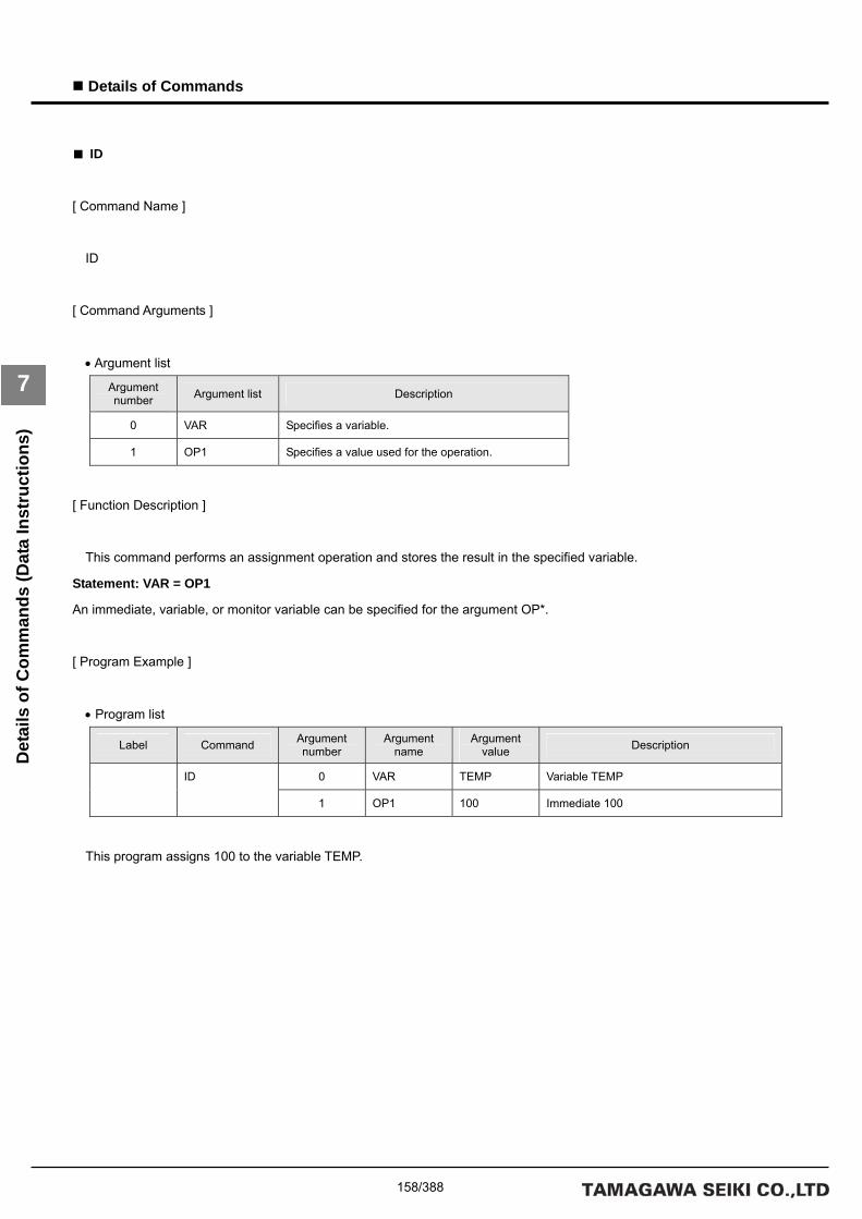
158/388
Details of Commands
7
Det
ails
of C
omm
ands
(Dat
a In
stru
ctio
ns)
■ ID
[ Command Name ]
ID
[ Command Arguments ]
• Argument list
Argument number Argument list Description
0 VAR Specifies a variable.
1 OP1 Specifies a value used for the operation.
[ Function Description ]
This command performs an assignment operation and stores the result in the specified variable.
Statement: VAR = OP1
An immediate, variable, or monitor variable can be specified for the argument OP*.
[ Program Example ]
• Program list
Label Command Argument number
Argument name
Argument value Description
0 VAR TEMP Variable TEMP ID
1 OP1 100 Immediate 100
This program assigns 100 to the variable TEMP.

159/388
Details of Commands
7
Det
ails
of C
omm
ands
(Dat
a In
stru
ctio
ns)
■ NOT
[ Command Name ]
NOT
[ Command Arguments ]
• Argument list
Argument number Argument list Description
0 VAR Specifies a variable.
1 OP1 Specifies a value used for the operation.
[ Function Description ]
This command performs a logical inversion operation and stores the result in the specified variable.
Statement: VAR = ~OP1
An immediate, variable, or monitor variable can be specified for the argument OP*.
[ Program Example ]
• Program list
Label Command Argument number
Argument name
Argument value Description
0 VAR TEMP Variable TEMP NOT
1 OP1 0x01 Immediate 0x01
This program stores 0xFE in the variable TEMP.

160/388
Details of Commands
7
Det
ails
of C
omm
ands
(Dat
a In
stru
ctio
ns)
■ NEG
[ Command Name ]
NEG
[ Command Arguments ]
• Argument list
Argument number Argument list Description
0 VAR Specifies a variable.
1 OP1 Specifies a value used for the operation.
[ Function Description ]
This command performs a sign inversion operation and stores the result in the specified variable.
Statement: VAR = -OP1
An immediate, variable, or monitor variable can be specified for the argument OP*.
[ Program Example ]
• Program list
Label Command Argument number
Argument name
Argument value Description
0 VAR TEMP Variable TEMP NEG
1 OP1 -100 Immediate -100
This program stores -100 in the variable TEMP.
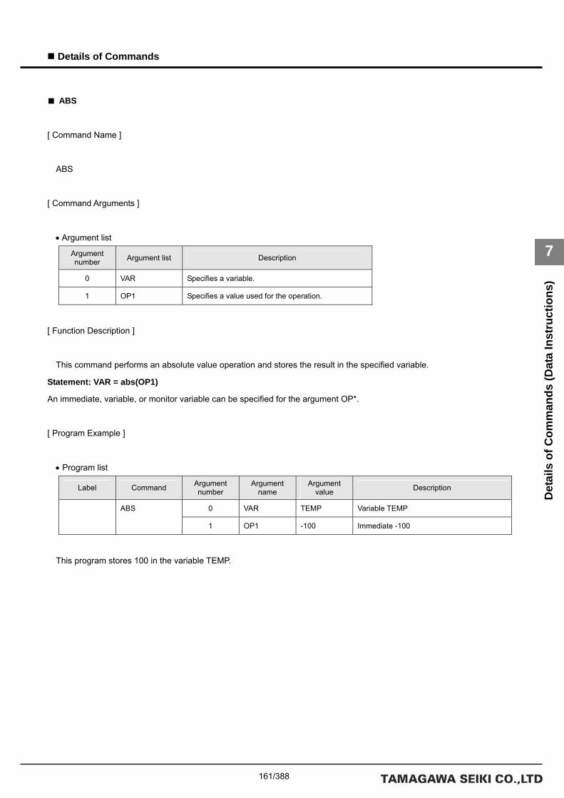
161/388
Details of Commands
7
Det
ails
of C
omm
ands
(Dat
a In
stru
ctio
ns)
■ ABS
[ Command Name ]
ABS
[ Command Arguments ]
• Argument list
Argument number Argument list Description
0 VAR Specifies a variable.
1 OP1 Specifies a value used for the operation.
[ Function Description ]
This command performs an absolute value operation and stores the result in the specified variable.
Statement: VAR = abs(OP1)
An immediate, variable, or monitor variable can be specified for the argument OP*.
[ Program Example ]
• Program list
Label Command Argument number
Argument name
Argument value Description
0 VAR TEMP Variable TEMP ABS
1 OP1 -100 Immediate -100
This program stores 100 in the variable TEMP.

162/388
Details of Commands
7
Det
ails
of C
omm
ands
(Dat
a In
stru
ctio
ns)
■ ADD
[ Command Name ]
ADD
[ Command Arguments ]
• Argument list
Argument number Argument list Description
0 VAR Specifies a variable.
1 OP1 Specifies a value used for the operation.
2 OP2 Specifies a value used for the operation.
[ Function Description ]
This command performs an addition operation and stores the result in the specified variable.
Statement: VAR = OP1 + OP2
An immediate, variable, or monitor variable can be specified for the argument OP*.
[ Program Example ]
• Program list
Label Command Argument number
Argument name
Argument value Description
0 VAR TEMP Variable TEMP
1 OP1 100 Immediate 100
ADD
2 OP2 100 Immediate 100
This program stores 200 in the variable TEMP.

163/388
Details of Commands
7
Det
ails
of C
omm
ands
(Dat
a In
stru
ctio
ns)
■ SUB
[ Command Name ]
SUB
[ Command Arguments ]
• Argument list
Argument number Argument list Description
0 VAR Specifies a variable.
1 OP1 Specifies a value used for the operation.
2 OP2 Specifies a value used for the operation.
[ Function Description ]
This command performs a subtraction operation and stores the result in the specified variable.
Statement: VAR = OP1 - OP2
An immediate, variable, or monitor variable can be specified for the argument OP*.
[ Program Example ]
• Program list
Label Command Argument number
Argument name
Argument value Description
0 VAR TEMP Variable TEMP
1 OP1 200 Immediate 200
SUB
2 OP2 100 Immediate 100
This program stores 100 in the variable TEMP.

164/388
Details of Commands
7
Det
ails
of C
omm
ands
(Dat
a In
stru
ctio
ns)
■ MUL
[ Command Name ]
MUL
[ Command Arguments ]
• Argument list
Argument number Argument list Description
0 VAR Specifies a variable.
1 OP1 Specifies a value used for the operation.
2 OP2 Specifies a value used for the operation.
[ Function Description ]
This command performs a multiplication operation and stores the result in the specified variable.
Statement: OP1 * OP2
An immediate, variable, or monitor variable can be specified for the argument OP*.
[ Program Example ]
• Program list
Label Command Argument number
Argument name
Argument value Description
0 VAR TEMP Variable TEMP
1 OP1 10 Immediate 10
MUL
2 OP2 10 Immediate 10
This program stores 100 in the variable TEMP.

165/388
Details of Commands
7
Det
ails
of C
omm
ands
(Dat
a In
stru
ctio
ns)
■ DIV
[ Command Name ]
DIV
[ Command Arguments ]
• Argument list
Argument number Argument list Description
0 VAR Specifies a variable.
1 OP1 Specifies a value used for the operation.
2 OP2 Specifies a value used for the operation.
[ Function Description ]
This command performs a division operation and stores the result in the specified variable.
Statement: VAR = OP1 / OP2
An immediate, variable, or monitor variable can be specified for the argument OP*.
[ Program Example ]
• Program list
Label Command Argument number
Argument name
Argument value Description
0 VAR TEMP Variable TEMP
1 OP1 100 Immediate 100
DIV
2 OP2 10 Immediate 10
This program stores 10 in the variable TEMP.

166/388
Details of Commands
7
Det
ails
of C
omm
ands
(Dat
a In
stru
ctio
ns)
■ MOD
[ Command Name ]
MOD
[ Command Arguments ]
• Argument list
Argument number Argument list Description
0 VAR Specifies a variable.
1 OP1 Specifies a value used for the operation.
2 OP2 Specifies a value used for the operation.
[ Function Description ]
This command performs a modulo operation and stores the result in the specified variable.
Statement: VAR = OP1 % OP2
An immediate, variable, or monitor variable can be specified for the argument OP*.
[ Program Example ]
• Program list
Label Command Argument number
Argument name
Argument value Description
0 VAR TEMP Variable TEMP
1 OP1 101 Immediate 101
MOD
2 OP2 100 Immediate 100
his program stores 1 in the variable TEMP.

167/388
Details of Commands
7
Det
ails
of C
omm
ands
(Dat
a In
stru
ctio
ns)
■ AND
[ Command Name ]
AND
[ Command Arguments ]
• Argument list
Argument number Argument list Description
0 VAR Specifies a variable.
1 OP1 Specifies a value used for the operation.
2 OP2 Specifies a value used for the operation.
[ Function Description ]
This command performs a logical conjunction operation and stores the result in the specified variable.
Statement: VAR = OP1 & OP2
An immediate, variable, or monitor variable can be specified for the argument OP*.
[ Program Example ]
• Program list
Label Command Argument number
Argument name
Argument value Description
0 VAR TEMP Variable TEMP
1 OP1 0x01 Immediate 0x01
AND
2 OP2 0xFF Immediate 0xFF
This program stores 0x01 in the variable TEMP.

168/388
Details of Commands
7
Det
ails
of C
omm
ands
(Dat
a In
stru
ctio
ns)
■ OR
[ Command Name ]
OR
[ Command Arguments ]
• Argument list
Argument number Argument list Description
0 VAR Specifies a variable.
1 OP1 Specifies a value used for the operation.
2 OP2 Specifies a value used for the operation.
[ Function Description ]
This command performs a logical disjunction operation and stores the result in the specified variable.
Statement: VAR = OP1 | OP2
An immediate, variable, or monitor variable can be specified for the argument OP*.
[ Program Example ]
• Program list
Label Command Argument number
Argument name
Argument value Description
0 VAR TEMP Variable TEMP
1 OP1 0xF0 Immediate 0xF0
OR
2 OP2 0x0F Immediate 0x0F
This program stores 0xFF in the variable TEMP.
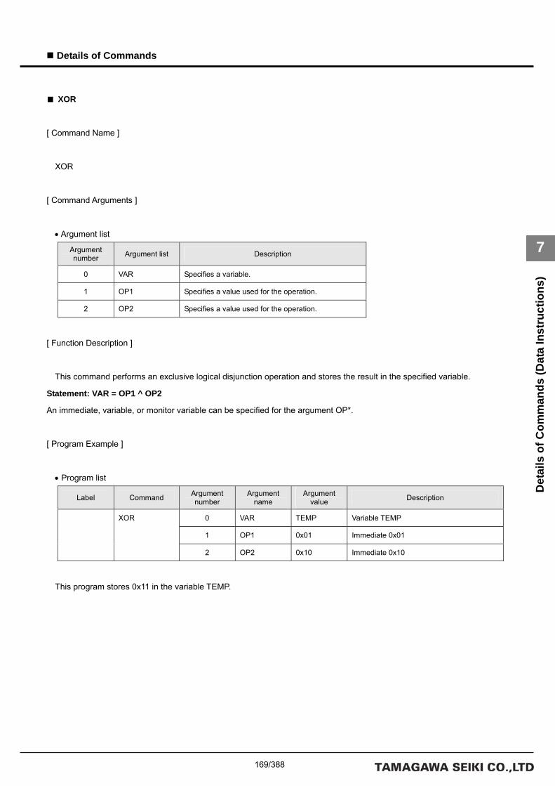
169/388
Details of Commands
7
Det
ails
of C
omm
ands
(Dat
a In
stru
ctio
ns)
■ XOR
[ Command Name ]
XOR
[ Command Arguments ]
• Argument list
Argument number Argument list Description
0 VAR Specifies a variable.
1 OP1 Specifies a value used for the operation.
2 OP2 Specifies a value used for the operation.
[ Function Description ]
This command performs an exclusive logical disjunction operation and stores the result in the specified variable.
Statement: VAR = OP1 ^ OP2
An immediate, variable, or monitor variable can be specified for the argument OP*.
[ Program Example ]
• Program list
Label Command Argument number
Argument name
Argument value Description
0 VAR TEMP Variable TEMP
1 OP1 0x01 Immediate 0x01
XOR
2 OP2 0x10 Immediate 0x10
This program stores 0x11 in the variable TEMP.

170/388
Details of Commands
7
Det
ails
of C
omm
ands
(Dat
a In
stru
ctio
ns)
■ ROT
[ Command Name ]
ROT
[ Command Arguments ]
• Argument list
Argument number Argument list Description
0 VAR Specifies a variable.
1 OP1 Specifies a value used for the operation.
2 OP2 Specifies a value used for the operation.
[ Function Description ]
This command performs a rotate operation and stores the result in the specified variable.
The shift direction depends on the sign of OP2.
A positive sign results in a leftward shift and a negative sign results in a rightward shift. In the case of a rightward shift, the
most significant bit (sign) is retained.
Statement: VAR = OP1 <<ROT +OP2 or VAR = OP1 ROT>> -OP2
An immediate, variable, or monitor variable can be specified for the argument OP*.
[ Program Example ]
• Program list
Label Command Argument number
Argument name
Argument value Description
0 VAR TEMP Variable TEMP
1 OP1 0x0F000000 Immediate 0x0F000000
ROT
2 OP2 16 Immediate 16
This program stores 0x00000F00 in the variable TEMP.
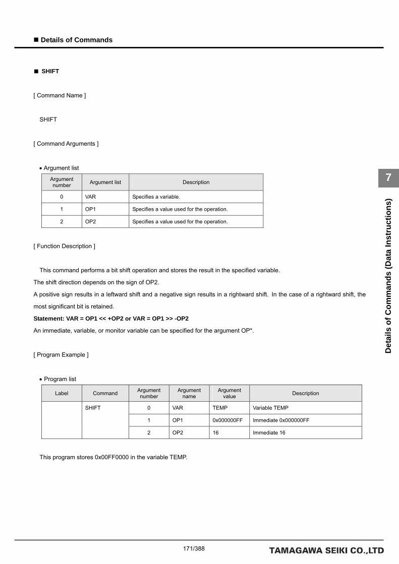
171/388
Details of Commands
7
Det
ails
of C
omm
ands
(Dat
a In
stru
ctio
ns)
■ SHIFT
[ Command Name ]
SHIFT
[ Command Arguments ]
• Argument list
Argument number Argument list Description
0 VAR Specifies a variable.
1 OP1 Specifies a value used for the operation.
2 OP2 Specifies a value used for the operation.
[ Function Description ]
This command performs a bit shift operation and stores the result in the specified variable.
The shift direction depends on the sign of OP2.
A positive sign results in a leftward shift and a negative sign results in a rightward shift. In the case of a rightward shift, the
most significant bit is retained.
Statement: VAR = OP1 << +OP2 or VAR = OP1 >> -OP2
An immediate, variable, or monitor variable can be specified for the argument OP*.
[ Program Example ]
• Program list
Label Command Argument number
Argument name
Argument value Description
0 VAR TEMP Variable TEMP
1 OP1 0x000000FF Immediate 0x000000FF
SHIFT
2 OP2 16 Immediate 16
This program stores 0x00FF0000 in the variable TEMP.

172/388
Details of Commands
7
Det
ails
of C
omm
ands
(Dat
a In
stru
ctio
ns)
■ FIELD1
[ Command Name ]
FIELD1
[ Command Arguments ]
• Argument list
Argument number Argument list Description
0 VAR Specifies a variable.
1 OP1 Specifies a value used for the operation.
2 OP2 Specifies a value used for the operation.
3 OP3 Specifies a value used for the operation.
[ Function Description ]
This command performs a field extraction operation and stores the result in the specified variable.
Statement: (OP1 & OP2) >> OP3
An immediate, variable, or monitor variable can be specified for the argument OP*.
[ Program Example ]
• Program list
Label Command Argument number
Argument name
Argument value Description
0 VAR TEMP Variable TEMP
1 OP1 0xFF Immediate 0xFF
2 OP2 0xF0 Immediate 0xF0
FIELD1
3 OP3 4 Immediate 4
This program stores 0x0F in the variable TEMP.

173/388
Details of Commands
7
Det
ails
of C
omm
ands
(Dat
a In
stru
ctio
ns)
■ FIELD2
[ Command Name ]
FIELD2
[ Command Arguments ]
• Argument list
Argument number Argument list Description
0 VAR Specifies a variable.
1 OP1 Specifies a value used for the operation.
2 OP2 Specifies a value used for the operation.
3 OP3 Specifies a value used for the operation.
[ Function Description ]
This command performs a field extraction operation and stores the result in the specified variable.
Statement: (OP1 & (( 2 << OP2 ) – 1 )) >> OP3
An immediate, variable, or monitor variable can be specified for the argument OP*.
[ Program Example ]
• Program list
Label Command Argument number
Argument name
Argument value Description
0 VAR TEMP Variable TEMP
1 OP1 0xFF Immediate 0xFF
2 OP2 2 Immediate 2
FIELD2
3 OP3 1 Immediate 1
This program stores 0x03 in the variable TEMP.

174/388
Details of Commands
7
Det
ails
of C
omm
ands
(Dat
a In
stru
ctio
ns)
■ SCALE
[ Command Name ]
SCALE
[ Command Arguments ]
• Argument list
Argument number Argument list Description
0 VAR Specifies a variable.
1 OP1 Specifies a value used for the operation.
2 OP2 Specifies a value used for the operation.
3 OP3 Specifies a value used for the operation.
[ Function Description ]
This command performs a scaling operation and stores the result in the specified variable.
Statement: VAR = (long)(OP1 * ((double)OP2 / OP3 ))
An immediate, variable, or monitor variable can be specified for the argument OP*.
[ Program Example ]
• Program list
Label Command Argument number
Argument name
Argument value Description
0 VAR TEMP Variable TEMP
1 OP1 10 Immediate 10
2 OP2 10 Immediate 10
SCALE
3 OP3 2 Immediate 2
This program stores 50 in the variable TEMP.

175/388
Details of Commands
7
Det
ails
of C
omm
ands
(Dat
a In
stru
ctio
ns)
■ SIN
[ Command Name ]
SIN
[ Command Arguments ]
• Argument list
Argument number Argument list Description
0 VAR Specifies a variable.
1 OP1 Specifies a value used for the operation.
2 OP2 Specifies a value used for the operation.
3 OP3 Specifies a value used for the operation.
[ Function Description ]
This command performs a sine operation and stores the result in the specified variable.
Statement: VAR = (long)(OP1 * sin((double)OP2 / OP3))
The unit for the arguments of the SIN function is the radian. An immediate, variable, or monitor variable can be specified for
the argument OP*.
[ Program Example ]
• Program list
Label Command Argument number
Argument name
Argument value Description
0 VAR TEMP Variable TEMP
1 OP1 10 Immediate 10
2 OP2 6 Immediate 6
SIN
3 OP3 12 Immediate 12
This program stores 5 in the variable TEMP.
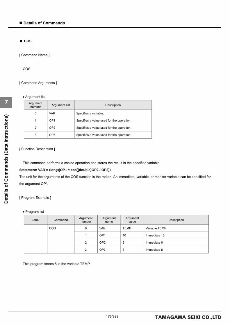
176/388
Details of Commands
7
Det
ails
of C
omm
ands
(Dat
a In
stru
ctio
ns)
■ COS
[ Command Name ]
COS
[ Command Arguments ]
• Argument list
Argument number Argument list Description
0 VAR Specifies a variable.
1 OP1 Specifies a value used for the operation.
2 OP2 Specifies a value used for the operation.
3 OP3 Specifies a value used for the operation.
[ Function Description ]
This command performs a cosine operation and stores the result in the specified variable.
Statement: VAR = (long)(OP1 * cos((double)OP2 / OP3))
The unit for the arguments of the COS function is the radian. An immediate, variable, or monitor variable can be specified for
the argument OP*.
[ Program Example ]
• Program list
Label Command Argument number
Argument name
Argument value Description
0 VAR TEMP Variable TEMP
1 OP1 10 Immediate 10
2 OP2 6 Immediate 6
COS
3 OP3 6 Immediate 6
This program stores 5 in the variable TEMP.

177/388
Details of Commands
7
Det
ails
of C
omm
ands
(Dat
a In
stru
ctio
ns)
■ MERGE
[ Command Name ]
MERGE
[ Command Arguments ]
• Argument list
Argument number Argument list Description
0 VAR Specifies a variable.
1 OP1 Specifies a value used for the operation.
2 OP2 Specifies a value used for the operation.
3 OP3 Specifies a value used for the operation.
[ Function Description ]
This command performs a merge operation and stores the result in the specified variable.
Statement: (OP1 & OP2) | (~OP1 & OP3)
An immediate, variable, or monitor variable can be specified for the argument OP*.
[ Program Example ]
• Program list
Label Command Argument number
Argument name
Argument value Description
0 VAR TEMP Variable TEMP
1 OP1 0xF0 Immediate 0xF0
2 OP2 0xF0 Immediate 0xF0
MERAGE
3 OP3 0x0F Immediate 0x0F
This program stores 0xFF in the variable TEMP.

178/388
Details of Commands
7
Det
ails
of C
omm
ands
(Dat
a In
stru
ctio
ns)
■ PRMGET
[ Command Name ]
PRMGET
[ Command Arguments ]
• Argument list
Argument number Argument list Description
0 CLS Specifies a class number.
1 GRP Specifies a group number.
2 ID Specifies the first ID number.
3 NUM Specifies the number of data elements to acquire.
4 VAR Specifies the storage destination variable (first).
[ Function Description ]
This command stores the specified parameter in the specified variable.
The command adds addresses for the number of data elements to acquire, beginning with the address specified for the
variable argument, and stores the data in the specified variable.
Note that if the variable and the number of data elements to acquire are not specified properly, variables referenced by other
instructions are rewritten.
It is recommended that the variable be defined in array form beforehand.
For the class number, group number, and ID number, refer to the Parameter List.
[ Program Example ]
• Program list
Label Command Argument number
Argument name
Argument value Description
0 CLS 0x2001 Class number Mechanism 1
1 GRP 1 Group number Axis 1
2 ID 1 Data ID number Data ID 1
3 NUM 2 Number of data elements to acquir 2
PRMGET
4 VAR ARR[0] First variable ARR[0]
This program stores the pulse rate numerator and the pulse rate denominator for Axis 1 of Mechanism 1 in the variable
ARR[0] and ARR[1], respectively.

179/388
Details of Commands
7
Det
ails
of C
omm
ands
(Dat
a In
stru
ctio
ns)
■ MONGET
[ Command Name ]
MONGET
[ Command Arguments ]
• Argument list
Argument number Argument list Description
0 CLS Specifies a class number.
1 GRP Specifies a group number.
2 ID Specifies the first ID number.
3 NUM Specifies the number of data elements to acquire.
4 VAR Specifies the storage destination variable (first).
[ Function Description ]
This command stores the specified monitor item in the specified variable.
The command adds addresses for the number of data elements to acquire, beginning with the address specified for the
variable argument, and stores the data in the specified variable.
Note that if the variable and the number of data elements to acquire are not specified properly, variables referenced by other
instructions are rewritten.
It is recommended that the variable be defined in array form beforehand.
For the class number, group number, and ID number, refer to the Monitor Item List.
[ Program Example ]
• Program list
Label Command Argument number
Argument name
Argument value Description
0 CLS 0x2001 Class number Mechanism 1
1 GRP 1 Group number Axis 1
2 ID 9 Data ID number Data ID 9
3 NUM 1 Number of data elements to acquire 1
MONGET
4 VAR ARR[0] First variable ARR[0]
This program stores the present actual position (instruction unit) for Axis 1 of Mechanism 1 in the variable ARR[0].

180/388
Details of Commands
7
Det
ails
of C
omm
ands
(Dat
a In
stru
ctio
ns)
■ COPY
[ Command Name ]
COPY
[ Command Arguments ]
• Argument list
Argument number Argument list Description
0 VAR_ADR1 Specifies the initial address for the copy destination variable.
1 VAR_ADR2 Specifies the initial address for the copy source variable.
2 SIZE Specifies the number of variables to be copied.
[ Function Description ]
This command copies the number of data items specified by SIZE from VAR_ADR2 to VAR_ADR1.
Specify the addresses of variables for VAR_ADR1 and VAR_ADR2. A value up to 255 can be specified for SIZE.
An alarm (at the task level) is returned if a value greater than 255 is specified for SIZE.
[ Program Example ]
• Program list
Label Command Argument number
Argument name
Argument value Description
0 VAR_ADR1 &TEMP1[0] Address of array variable TEMP[0]
1 VAR_ADR2 &TEMP2[0] Address of array variable TEMP2[0]
COPY
2 SIZE 10 Copy size: 10
This program copies the values of TEMP2[0]–TEMP2[9] to TEMP1[0]–TEMP1[9].
TEMP1[0] = TEMP2[0]
TEMP1[1] = TEMP2[1]
:
TEMP1[9] = TEMP2[9]

181/388
Details of Commands
7
Det
ails
of C
omm
ands
(Bra
nch
Inst
ruct
ions
)
Details of Branch Instructions

182/388
Details of Commands
7
Det
ails
of C
omm
ands
(Bra
nch
Inst
ruct
ions
)
■ JMP0
[ Command Name ]
JMP0
[ Command Arguments ]
• Argument list
Argument number Argument list Description
0 LABEL Specifies the branch destination label.
[ Function Description ]
This command transfers control to the index specified as the branch destination label unconditionally.
[ Program Example ]
• Program list
Label Command Argument number
Argument name
Argument value Description
JMP0 0 LABEL L1 Branch destination label L1
This program causes a jump to branch destination label L1.

183/388
Details of Commands
7
Det
ails
of C
omm
ands
(Bra
nch
Inst
ruct
ions
)
■ JMP1
[ Command Name ]
JMP1
[ Command Arguments ]
• Argument list
Argument number Argument list Description
0 LABEL Specifies the branch destination label.
1 OP1 Specifies a value used for the conditional statement.
[ Function Description ]
This command transfers control to the index specified as the branch destination label if the condition is satisfied.
Conditional statement: OP1 != 0 (The condition is satisfied if OP1 is not 0.)
An immediate, variable, or monitor variable can be specified for the argument OP*.
[ Program Example ]
• Program list
Label Command Argument number
Argument name
Argument value Description
0 LABEL L1 Branch destination label L1 JMP1
1 OP1 TEMP Variable TEMP
This program causes a jump to branch destination label L1 if the variable TEMP is not 0.

184/388
Details of Commands
7
Det
ails
of C
omm
ands
(Bra
nch
Inst
ruct
ions
)
■ JMPAND
[ Command Name ]
JMPAND
[ Command Arguments ]
• Argument list
Argument number Argument list Description
0 LABEL Specifies the branch destination label.
1 OP1 Specifies a value used for the conditional statement.
2 OP2 Specifies a value used for the conditional statement.
[ Function Description ]
This command transfers control to the index specified as the branch destination label if the condition is satisfied.
Conditional statement: OP1 & OP2 (The condition is satisfied if the operation result is not 0.)
An immediate, variable, or monitor variable can be specified for the argument OP*.
[ Program Example ]
• Program list
Label Command Argument number
Argument name
Argument value Description
0 LABEL L1 Branch destination label L1
1 OP1 TEMP Variable TEMP
JMPAND
2 OP2 0x01 Immediate 0x01
This program causes a jump to branch destination label L1 if the variable TEMP & 0x01 is not 0.

185/388
Details of Commands
7
Det
ails
of C
omm
ands
(Bra
nch
Inst
ruct
ions
)
■ JMPEQ
[ Command Name ]
JMPEQ
[ Command Arguments ]
• Argument list
Argument number Argument list Description
0 LABEL Specifies the branch destination label.
1 OP1 Specifies a value used for the conditional statement.
2 OP2 Specifies a value used for the conditional statement.
[ Function Description ]
This command transfers control to the index specified as the branch destination label if the condition is satisfied.
Conditional statement: OP1 == OP2 (The condition is satisfied with an equal sign relation.)
An immediate, variable, or monitor variable can be specified for the argument OP*.
[ Program Example ]
• Program list
Label Command Argument number
Argument name
Argument value Description
0 LABEL L1 Branch destination label L1
1 OP1 TEMP Variable TEMP
JMPEQ
2 OP2 10 Immediate 10
This program causes a jump to branch destination label L1 if the variable TEMP is 10.

186/388
Details of Commands
7
Det
ails
of C
omm
ands
(Bra
nch
Inst
ruct
ions
)
■ JMPNE
[ Command Name ]
JMPNE
[ Command Arguments ]
• Argument list
Argument number Argument list Description
0 LABEL Specifies the branch destination label.
1 OP1 Specifies a value used for the conditional statement.
2 OP2 Specifies a value used for the conditional statement.
[ Function Description ]
This command transfers control to the index specified as the branch destination label if the condition is satisfied.
Conditional statement: OP1 != OP2 (The condition is satisfied with an unequal sign relation.)
An immediate, variable, or monitor variable can be specified for the argument OP*.
[ Program Example ]
• Program list
Label Command Argument number
Argument name
Argument value Description
0 LABEL L1 Branch destination label L1
1 OP1 TEMP Variable TEMP
JMPNE
2 OP2 10 Immediate 10
This program causes a jump to branch destination label L1 if the variable TEMP is not 10.

187/388
Details of Commands
7
Det
ails
of C
omm
ands
(Bra
nch
Inst
ruct
ions
)
■ JMPLT
[ Command Name ]
JMPLT
[ Command Arguments ]
• Argument list
Argument number Argument list Description
0 LABEL Specifies the branch destination label.
1 OP1 Specifies a value used for the conditional statement.
2 OP2 Specifies a value used for the conditional statement.
[ Function Description ]
This command transfers control to the index specified as the branch destination label if the condition is satisfied.
Conditional statement: OP1 < OP2 (The condition is satisfied with a less than relation.)
An immediate, variable, or monitor variable can be specified for the argument OP*.
[ Program Example ]
• Program list
Label Command Argument number
Argument name
Argument value Description
0 LABEL L1 Branch destination label L1
1 OP1 TEMP Variable TEMP
JMPLT
2 OP2 10 Immediate 10
This program causes a jump to branch destination label L1 if the variable TEMP is less than 10.

188/388
Details of Commands
7
Det
ails
of C
omm
ands
(Bra
nch
Inst
ruct
ions
)
■ JMPGT
[ Command Name ]
JMPGT
[ Command Arguments ]
• Argument list
Argument number Argument list Description
0 LABEL Specifies the branch destination label.
1 OP1 Specifies a value used for the conditional statement.
2 OP2 Specifies a value used for the conditional statement.
[ Function Description ]
This command transfers control to the index specified as the branch destination label if the condition is satisfied.
Conditional statement: OP1 > OP2 (The condition is satisfied with a greater than relation.)
An immediate, variable, or monitor variable can be specified for the argument OP*.
[ Program Example ]
• Program list
Label Command Argument number
Argument name
Argument value Description
0 LABEL L1 Branch destination label L1
1 OP1 TEMP Variable TEMP
JMPGT
2 OP2 10 Immediate 10
This program causes a jump to branch destination label L1 if the variable TEMP is greater than 10.

189/388
Details of Commands
7
Det
ails
of C
omm
ands
(Bra
nch
Inst
ruct
ions
)
■ JMPLE
[ Command Name ]
JMPLE
[ Command Arguments ]
• Argument list
Argument number Argument list Description
0 LABEL Specifies the branch destination label.
1 OP1 Specifies a value used for the conditional statement.
2 OP2 Specifies a value used for the conditional statement.
[ Function Description ]
This command transfers control to the index specified as the branch destination label if the condition is satisfied.
Conditional statement: OP1 <= OP2 (The condition is satisfied with an equal to or less than relation.)
An immediate, variable, or monitor variable can be specified for the argument OP*.
[ Program Example ]
• Program list
Label Command Argument number
Argument name
Argument value Description
0 LABEL L1 Branch destination label L1
1 OP1 TEMP Variable TEMP
JMPLE
2 OP2 10 Immediate 10
This program causes a jump to branch destination label L1 if the variable TEMP is equal to or less than 10.

190/388
Details of Commands
7
Det
ails
of C
omm
ands
(Bra
nch
Inst
ruct
ions
)
■ JMPGE
[ Command Name ]
JMPGE
[ Command Arguments ]
• Argument list
Argument number Argument list Description
0 LABEL Specifies the branch destination label.
1 OP1 Specifies a value used for the conditional statement.
2 OP2 Specifies a value used for the conditional statement.
[ Function Description ]
This command transfers control to the index specified as the branch destination label if the condition is satisfied.
Conditional statement: OP1 >= OP2 (The condition is satisfied with an equal to or greater than relation.)
An immediate, variable, or monitor variable can be specified for the argument OP*.
[ Program Example ]
• Program list
Label Command Argument number
Argument name
Argument value Description
0 LABEL L1 Branch destination label L1
1 OP1 TEMP Variable TEMP
JMPGE
2 OP2 10 Immediate 10
This program causes a jump to branch destination label L1 if the variable TEMP is equal to or greater than 10.

191/388
Details of Commands
7
Det
ails
of C
omm
ands
(Bra
nch
Inst
ruct
ions
)
■ JMPBIT
[ Command Name ]
JMPBIT
[ Command Arguments ]
• Argument list
Argument number Argument list Description
0 LABEL Specifies the branch destination label.
1 VAR Specifies a variable used for the conditional
statement.
2 SETUP Specifies a value used for the conditional statement.
[ Function Description ]
This command transfers control to the index specified as the branch destination label if the condition is satisfied.
Conditional statement: The variable value is ON at the bit position specified for SETUP.
If multiple bits are specified for SETUP, the condition is satisfied if all the specified bits are ON.
Only a variable can be specified for the argument VAR. Only an immediate or variable can be specified for the argument
SETUP.
[ Program Example ]
• Program list
Label Command Argument number
Argument name
Argument value Description
0 LABEL L1 Branch destination label L1
1 VAR TEMP Variable TEMP
JMPBIT
2 SETUP 0x0F Immediate 0x0F
This program causes a jump to branch destination label L1 if the variable TEMP is 0x0F.

192/388
Details of Commands
7
Det
ails
of C
omm
ands
(Bra
nch
Inst
ruct
ions
)
■ JNPBIT
[ Command Name ]
JNPBIT
[ Command Arguments ]
• Argument list
Argument number Argument list Description
0 LABEL Specifies the branch destination label.
1 VAR Specifies a variable used for the conditional
statement.
2 SETUP Specifies a value used for the conditional statement.
[ Function Description ]
This command transfers control to the index specified as the branch destination label if the condition is satisfied.
Conditional statement: The variable value is OFF at the bit position specified for SETUP.
If multiple bits are specified for SETUP, the condition is satisfied if all the specified bits are OFF.
Only a variable can be specified for the argument VAR. Only an immediate or variable can be specified for the argument
SETUP.
[ Program Example ]
• Program list
Label Command Argument number
Argument name
Argument value Description
0 LABEL L1 Branch destination label L1
1 VAR TEMP Variable TEMP
JNPBIT
2 SETUP 0x0F Immediate 0x0F
This program causes a jump to branch destination label L1 if the variable TEMP is OFF at all bit positions specified for
SETUP.

193/388
Details of Commands
7
Det
ails
of C
omm
ands
(Bra
nch
Inst
ruct
ions
)
■ JMPAXIS
[ Command Name ]
JMPAXIS [ Command Arguments ]
• Argument list
Argument number Argument list Description
0 LABEL Specifies the branch destination label.
1 MCH Specifies a mechanism number.
2 SETUP Specifies a setup axis number.
3 PASS Specifies a PASS point.
[ Function Description ]
This command transfers control to the index specified as the branch destination label if the condition is satisfied.
Conditional statement: PASS point (The condition is satisfied if the PASS point is established on any of the axes
specified for SETUP.)
The PASS point is specified as follows:
PASS point value PASS point
1 The condition is satisfied if interpolation calculation is in progress.
2 The condition is satisfied if deceleration processing is in progress.
4 The condition is satisfied if the axis is moving.
8 The condition is satisfied if homing is in progress.
[ Program Example ]
• Program list
Label Command Argument number
Argument name
Argument value Description
0 LABEL L1 Branch destination label L1
1 MCH 0 Mechanism 0
2 SETUP 0x07 Axes 1, 2, and 3
JMPAXIS
3 PASS 4 The axis is moving at the PASS point.
If Axis 1, 2, or 3 of Mechanism 0 is moving (non in-position), the condition is satisfied and the program causes a jump to
branch destination label L1.

194/388
Details of Commands
7
Det
ails
of C
omm
ands
(Bra
nch
Inst
ruct
ions
)
■ JMPMCH
[ Command Name ]
JMPMCH
[ Command Arguments ]
• Argument list
Argument number Argument list Description
0 LABEL Specifies the branch destination label.
1 MCH Specifies a mechanism number.
2 PASS Specifies a setup axis number.
[ Function Description ]
This command transfers control to the index specified as the branch destination label if the condition is satisfied.
Conditional statement: PASS point (The condition is satisfied if the PASS point is established on any of the axes
belonging to the mechanism.)
The PASS point is specified as follows:
PASS point value PASS point
1 The condition is satisfied if interpolation calculation is in progress.
2 The condition is satisfied if deceleration processing is in progress.
4 The condition is satisfied if the axis is moving.
8 The condition is satisfied if homing is in progress.
[ Program Example ]
• Program list
Label Command Argument number
Argument name
Argument value Description
0 LABEL L1 Branch destination label L1
1 MCH 0 Mechanism 0
JMPMCH
2 PASS 4 The axis is moving at the PASS point.
If an axis in Mechanism 0 is moving (non in-position), the condition is satisfied and the program causes a jump to branch
destination label L1.

195/388
Details of Commands
7
Det
ails
of C
omm
ands
(Bra
nch
Inst
ruct
ions
)
■ JMPDIO
[ Command Name ]
JMPDIO
[ Command Arguments ]
• Argument list
Argument number Argument list Description
0 LABEL Specifies the branch destination label.
1 DIO Specifies a DIO number.
2 SETUP Specifies a value used for the conditional statement.
[ Function Description ]
This command transfers control to the index specified as the branch destination label if the condition is satisfied.
Conditional statement: The DIO input value is ON at the bit position specified for SETUP.
If multiple bits are specified for SETUP, the condition is satisfied if all the specified bits are ON.
[ Program Example ]
• Program list
Label Command Argument number
Argument name
Argument value Description
0 LABEL L1 Branch destination label L1
1 DIO 0 DIO 0
JMPDIO
2 SETUP 0x0F Immediate 0x0F
If input BIT0 to BIT3 of DIO_0 are ON, the condition is satisfied and the program causes a jump to branch destination label
L1.

196/388
Details of Commands
7
Det
ails
of C
omm
ands
(Bra
nch
Inst
ruct
ions
)
■ JNPDIO
[ Command Name ]
JNPDIO
[ Command Arguments ]
• Argument list
Argument number Argument list Description
0 LABEL Specifies the branch destination label.
1 DIO Specifies a DIO number.
2 SETUP Specifies a value used for the conditional statement.
[ Function Description ]
This command transfers control to the index specified as the branch destination label if the condition is satisfied.
Conditional statement: The DIO input value is OFF at the bit position specified for SETUP.
If multiple bits are specified for SETUP, the condition is satisfied if all the specified bits are OFF.
[ Program Example ]
• Program list
Label Command Argument number
Argument name
Argument value Description
0 LABEL L1 Branch destination label L1
1 DIO 0 DIO 0
JNPDIO
2 SETUP 0x0F Immediate 0x0F
If input BIT0 to BIT3 of DIO_0 are OFF, the condition is satisfied and the program causes a jump to branch destination label
L1.

197/388
Details of Commands
7
Det
ails
of C
omm
ands
(Bra
nch
Inst
ruct
ions
)
■ CALL
[ Command Name ]
CALL
[ Command Arguments ]
• Argument list
Argument number Argument list Description
0 LABEL Specifies a subroutine label.
[ Function Description ]
This command pushes the next index to the stack.
Then, the command transfers control to the index specified on the subroutine label.
[ Program Example ]
• Program list
Label Command Argument number
Argument name
Argument value Description
CALL 0 LABEL L1 Subroutine label S1
This program calls subroutine S1.
• Notes on the use of the CALL command
(A) Be sure to return control to the calling source by a RET instruction issued from the called subroutine.
If the RET instruction is omitted, the program operation is not recognized.
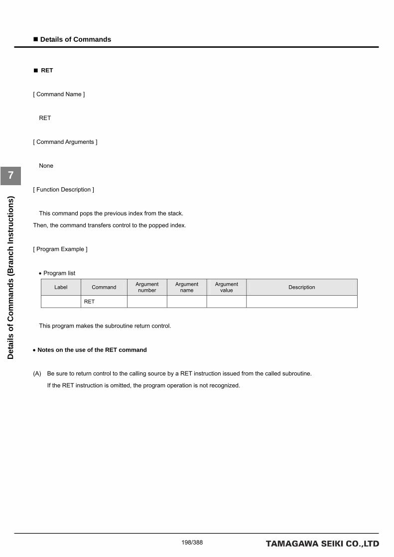
198/388
Details of Commands
7
Det
ails
of C
omm
ands
(Bra
nch
Inst
ruct
ions
)
■ RET
[ Command Name ]
RET
[ Command Arguments ]
None
[ Function Description ]
This command pops the previous index from the stack.
Then, the command transfers control to the popped index.
[ Program Example ]
• Program list
Label Command Argument number
Argument name
Argument value Description
RET
This program makes the subroutine return control.
• Notes on the use of the RET command
(A) Be sure to return control to the calling source by a RET instruction issued from the called subroutine.
If the RET instruction is omitted, the program operation is not recognized.

199/388
Details of Commands
7
Det
ails
of C
omm
ands
(Tas
k In
stru
ctio
ns)
Details of Task Instructions

200/388
Details of Commands
7
Det
ails
of C
omm
ands
(Tas
k In
stru
ctio
ns)
■ TSTART
[ Command Name ]
TSTART
[ Command Arguments ]
• Argument list
Argument number Argument list Description
0 LABEL Specifies a task start label.
1 TASK Specifies a task number.
[ Function Description ]
This command starts a task. All stack points are released.
[ Program Example ]
• Program list
Label Command Argument number
Argument name
Argument value Description
0 LABEL T1 Task start label T1 TSTART
1 TASK 1 Task 1
This program starts Task 1 and executes it beginning with the task start label T1.

201/388
Details of Commands
7
Det
ails
of C
omm
ands
(Tas
k In
stru
ctio
ns)
■ GETTID
[ Command Name ]
GETTID
[ Command Arguments ]
• Argument list
Argument number Argument list Description
0 VAR Specifies a variable.
[ Function Description ]
This command obtains the ID of the current task and stores it in the specified variable.
[ Program Example ]
• Program list
Label Command Argument number
Argument name
Argument value Description
GETTID 0 VAR TEMP Variable TEMP
This command stores the ID number of the executed task in the variable TEMP.

202/388
Details of Commands
7
Det
ails
of C
omm
ands
(Tas
k In
stru
ctio
ns)
■ GETTST
[ Command Name ]
GETTST
[ Command Arguments ]
• Argument list
Argument number Argument list Description
0 VAR Specifies a variable.
1 TASK Specifies a task number.
[ Function Description ]
This command obtains the starting status of the specified task and stores it in the specified variable.
The starting status is 1 if the task is active and 0 if the task is stopped.
[ Program Example ]
• Program list
Label Command Argument number
Argument name
Argument value Description
0 VAR TEMP Variable TEMP GETTST
1 TASK 1 Task 1
This program stores the status of Task 1 in the variable TEMP.

203/388
Details of Commands
7
Det
ails
of C
omm
ands
(Tas
k In
stru
ctio
ns)
■ TRESTART
[ Command Name ]
TRESTART
[ Command Arguments ]
• Argument list
Argument number Argument list Description
0 TASK Specifies a task number.
[ Function Description ]
This command restarts a task. The task is started from the current index.
The stack pointer retains its current status.
[ Program Example ]
• Program list
Label Command Argument number
Argument name
Argument value Description
TRESTART 0 TASK 1 Task 1
This program restarts Task 1.

204/388
Details of Commands
7
Det
ails
of C
omm
ands
(Tas
k In
stru
ctio
ns)
■ TSTEP
[ Command Name ]
TSTEP
[ Command Arguments ]
• Argument list
Argument number Argument list Description
0 TASK Specifies a task number.
[ Function Description ]
This command step-executes a task. It step-executes the current task index.
If a task that has already started is executed, the task is stopped after the current index is executed.
[ Program Example ]
• Program list
Label Command Argument number
Argument name
Argument value Description
TRESTART 0 TASK 1 Task 1
This program step-executes Task 1.

205/388
Details of Commands
7
Det
ails
of C
omm
ands
(Tas
k In
stru
ctio
ns)
■ TEND
[ Command Name ]
TEND
[ Command Arguments ]
• Argument list
Argument number Argument list Description
0 TASK Specifies a task number.
[ Function Description ]
This command stops a task.
[ Program Example ]
• Program list
Label Command Argument number
Argument name
Argument value Description
TEND 0 TASK 1 Task 1
This program stops Task 1.

206/388
Details of Commands
7
Det
ails
of C
omm
ands
(Tas
k In
stru
ctio
ns)

207/388
Details of Commands
7
Det
ails
of C
omm
ands
(Tim
er In
stru
ctio
ns)
Details of Timer Instructions

208/388
Details of Commands
7
Det
ails
of C
omm
ands
(Tim
er In
stru
ctio
ns)
■ TIME
[ Command Name ]
TIME
[ Command Arguments ]
• Argument list
Argument number Argument list Description
0 TIMER Specifies a timer number.
1 OP1 Specifies a value to which this command initializes the
timer.
[ Function Description ]
This command initializes a timer.
Statement: TIMER = OP1
Specify a timer number for the argument TIMER. An immediate, variable, or monitor variable can be specified for the
argument OP*.
[ Program Example ]
• Program list
Label Command Argument number
Argument name
Argument value Description
0 TIMER 1 Timer number 1 TIME
1 OP1 0 Immediate 0
This program initializes Timer 1 to 0.
• Notes on the use of the TIME command
(A) If a TIME command is used for multiple tasks, do not use the same timer number for them.

209/388
Details of Commands
7
Det
ails
of C
omm
ands
(Tim
er In
stru
ctio
ns)
■ WAIT
[ Command Name ]
WAIT
[ Command Arguments ]
• Argument list
Argument number Argument list Description
0 TIMER Specifies a timer number.
1 WAIT Specifies a wait time. (Unit: msec)
[ Function Description ]
This command places the program in a simple wait status.
The specified timer is initialized to 0 and the program waits at the current index until the specified wait time has elapsed.
[ Program Example ]
• Program list
Label Command Argument number
Argument name
Argument value Description
0 TIMER 0 Timer number 0 WAIT
1 WAIT 500 Wait time 500 msec
This program causes a wait of 500 msec by using Timer 0.
• Notes on the use of the WAIT command
(A) If a WAIT command is used for multiple tasks, do not use the same timer number for them.

210/388
Details of Commands
7
Det
ails
of C
omm
ands
(Tim
er In
stru
ctio
ns)

211/388
Details of Commands
7
Det
ails
of C
omm
ands
(I/O
Inst
ruct
ions
)
Details of I/O Instructions

212/388
Details of Commands
7
Det
ails
of C
omm
ands
(I/O
Inst
ruct
ions
)
■ DOUT
[ Command Name ]
DOUT
[ Command Arguments ]
• Argument list
Argument number Argument list Description
0 DIO Specifies a DIO number.
1 OP1 Specifies data to output.
[ Function Description ]
This command outputs data to the specified DIO number.
Statement: DIO = OP1
Specify a DIO number for the argument DIO. An immediate, variable, or monitor variable can be specified for the argument
OP*.
[ Program Example ]
• Program list
Label Command Argument number
Argument name
Argument value Description
0 DIO 0 DIO number 0 DOUT
1 OP1 0x0F Immediate 0x0F
This program outputs 0x0F to DIO_0.

213/388
Details of Commands
7
Det
ails
of C
omm
ands
(I/O
Inst
ruct
ions
)
■ DIN
[ Command Name ]
DIN
[ Command Arguments ]
• Argument list
Argument number Argument list Description
0 VAR Specifies a variable in which the input data is stored.
1 DIO Specifies a DIO number.
[ Function Description ]
This command stores the input data of the specified DIO number in the specified variable.
Statement: VAR = DIO
Specify a variable for the argument VAR and a DIO number for the argument DIO.
[ Program Example ]
• Program list
Label Command Argument number
Argument name
Argument value Description
0 VAR TEMP Variable TEMP DIN
1 DIO 0 DIO number 0
This program stores the input data of DIO_0 in the variable TEMP.

214/388
Details of Commands
7
Det
ails
of C
omm
ands
(I/O
Inst
ruct
ions
)
■ AOUT
[ Command Name ]
AOUT
[ Command Arguments ]
• Argument list
Argument number Argument list Description
0 AIO Specifies an AIO channel number.
1 OP1 Specifies data to output.
[ Function Description ]
This command outputs data to the specified AIO channel number.
Statement: AIO = OP1
Specify an AIO channel number for the argument AIO. An immediate, variable, or monitor variable can be specified for the
argument OP*.
[ Program Example ]
• Program list
Label Command Argument number
Argument name
Argument value Description
0 AIO 0 AIO channel 0 AOUT
1 OP1 1024 Immediate 1024
This program outputs 1024 to AIO channel 0.

215/388
Details of Commands
7
Det
ails
of C
omm
ands
(I/O
Inst
ruct
ions
)
■ AIN
[ Command Name ]
AIN
[ Command Arguments ]
• Argument list
Argument number Argument list Description
0 VAR Specifies a variable in which the input data is stored.
1 AIO Specifies an AIO channel number.
[ Function Description ]
This command stores the input data of the specified AIO channel in the specified variable.
Statement: VAR = AIO
Specify a variable for the argument VAR and an AIO channel number for the argument AIO.
[ Program Example ]
• Program list
Label Command Argument number
Argument name
Argument value Description
0 VAR TEMP Variable TEMP AIN
1 AIO 0 AIO channel 0
This program stores the data of AIO channel 0 in the variable TEMP.

216/388
Details of Commands
7
Det
ails
of C
omm
ands
(I/O
Inst
ruct
ions
)
■ BITON
[ Command Name ]
BITON
[ Command Arguments ]
• Argument list
Argument number Argument list Description
0 DIO Specifies a DIO number.
1 OP1 Specifies data to be output to the DIO.
[ Function Description ]
This command outputs data to the specified DIO number.
Statement: DIO |= OP1
The bit specified to be 1 by OP1 is turned ON. Nothing is done for the bits that are not specified to be 1.
Specify a DIO number for DIO.
[ Program Example ]
• Program list
Label Command Argument number
Argument name
Argument value Description
0 DIO 0 DIO 0 BITON
1 OP1 0x5555 Immediate 0x5555
This program turns ON the bit specified to be 1 by OP1.
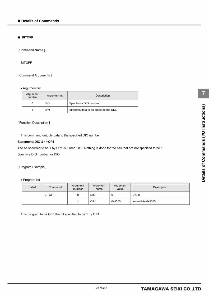
217/388
Details of Commands
7
Det
ails
of C
omm
ands
(I/O
Inst
ruct
ions
)
■ BITOFF
[ Command Name ]
BITOFF
[ Command Arguments ]
• Argument list
Argument number Argument list Description
0 DIO Specifies a DIO number.
1 OP1 Specifies data to be output to the DIO.
[ Function Description ]
This command outputs data to the specified DIO number.
Statement: DIO &= ~OP1
The bit specified to be 1 by OP1 is turned OFF. Nothing is done for the bits that are not specified to be 1.
Specify a DIO number for DIO.
[ Program Example ]
• Program list
Label Command Argument number
Argument name
Argument value Description
0 DIO 0 DIO 0 BITOFF
1 OP1 0x5555 Immediate 0x5555
This program turns OFF the bit specified to be 1 by OP1.

218/388
Details of Commands
7
Det
ails
of C
omm
ands
(I/O
Inst
ruct
ions
)
■ BITIN
[ Command Name ]
BITIN
[ Command Arguments ]
• Argument list
Argument number Argument list Description
0 VAR Specifies a variable name.
1 DIO Specifies a DIO number to be input.
2 MASK Specifies a bit to be input.
[ Function Description ]
This command stores only the bit set to 1 by the MASK argument, among the bits of the specified DIO number, in the
specified variable.
Statement: VAR = DIO & MASK
Bits that are not set to 1 by the MASK argument are set to 0.
[ Program Example ]
• Program list
Label Command Argument number
Argument name
Argument value Description
0 VAR TEMP Variable TEMP
1 DIO 0 DIO 0
BITIN
2 MASK 0x5555 Immediate 0x5555
The input of DIO 0 and the data masked by the immediate 0x5555 are stored in the variable TEMP.

219/388
Details of Commands
7
Det
ails
of C
omm
ands
(PA
SS In
stru
ctio
ns)
Details of PASS Instructions

220/388
Details of Commands
7
Det
ails
of C
omm
ands
(PA
SS In
stru
ctio
ns)
■ PASSM
[ Command Name ]
PASSM
[ Command Arguments ]
• Argument list
Argument number Argument list Description
0 MCH Specifies a mechanism number.
[ Function Description ]
This command places the program in a wait status at the current index until interpolation calculation has been completed
for all the axes belonging to the mechanism.
Unlike for JMPMCH, no branch destination label can be specified in this command.
[ Program Example ]
• Program list
Label Command Argument number
Argument name
Argument value Description
PASSM 0 MCH 0 Mechanism 0
The program is placed in a wait status at the current index until interpolation calculation has been completed for all the axes
in Mechanism 0.
• Notes on the use of the PASSM command
(A) Use an individual-axis PASS instruction (PASSA, DECELA, INPOSA, or ORGA) if the axis move instruction is used for
multiple tasks.

221/388
Details of Commands
7
Det
ails
of C
omm
ands
(PA
SS In
stru
ctio
ns)
■ DECELM
[ Command Name ]
DECELM
[ Command Arguments ]
• Argument list
Argument number Argument list Description
0 MCH Specifies a mechanism number.
[ Function Description ]
This command places the program in a wait status at the current index until deceleration has been completed for all the
axes belonging to the mechanism.
Unlike for JMPMCH, no branch destination label can be specified in this command.
[ Program Example ]
• Program list
Label Command Argument number
Argument name
Argument value Description
DECELM 0 MCH 0 Mechanism 0
The program is placed in a wait status at the current index until deceleration processing has been completed for all the
axes in Mechanism 0.
• Notes on the use of the DECELM command
(A) Use an individual-axis PASS instruction (PASSA, DECELA, INPOSA, or ORGA) if the axis move instruction is used for
multiple tasks.

222/388
Details of Commands
7
Det
ails
of C
omm
ands
(PA
SS In
stru
ctio
ns)
■ INPOSM
[ Command Name ]
INPOSM
[ Command Arguments ]
• Argument list
Argument number Argument list Description
0 MCH Specifies a mechanism number.
[ Function Description ]
This command places the program in a wait status at the current index until all the axes belonging to the mechanism have
been placed in position.
Unlike for JMPMCH, no branch destination label can be specified in this command.
[ Program Example ]
• Program list
Label Command Argument number
Argument name
Argument value Description
INPOSM 0 MCH 0 Mechanism 0
The program is placed in a wait status at the current index until all the axes in Mechanism 0 have been placed in position.
• Notes on the use of the INPOSM command
(A) Use an individual-axis PASS instruction (PASSA, DECELA, INPOSA, or ORGA) if the axis move instruction is used for
multiple tasks.

223/388
Details of Commands
7
Det
ails
of C
omm
ands
(PA
SS In
stru
ctio
ns)
■ ORGM
[ Command Name ]
ORGM
[ Command Arguments ]
• Argument list
Argument number Argument list Description
0 MCH Specifies a mechanism number.
[ Function Description ]
This command places the program in a wait status at the current index until homing has been completed for all the axes
belonging to the mechanism.
Unlike for JMPMCH, no branch destination label can be specified in this command.
[ Program Example ]
• Program list
Label Command Argument number
Argument name
Argument value Description
ORGM 0 MCH 0 Mechanism 0
The program is placed in a wait status at the current index until homing has been completed for all the axes in Mechanism
0.
• Notes on the use of the ORGM command
(A) Use an individual-axis PASS instruction (PASSA, DECELA, INPOSA, or ORGA) if the axis move instruction is used for
multiple tasks.

224/388
Details of Commands
7
Det
ails
of C
omm
ands
(PA
SS In
stru
ctio
ns)
■ PASSA
[ Command Name ]
PASSA
[ Command Arguments ]
• Argument list
Argument number Argument list Description
0 MCH Specifies a mechanism number.
1 SETUP Specifies a setup axis number.
[ Function Description ]
This command places the program in a wait status at the current index until interpolation calculation has been completed
for all the axes specified by the mechanism number and the setup axis number.
Unlike for JMPAXIS, no branch destination label can be specified in this command.
[ Program Example ]
• Program list
Label Command Argument number
Argument name
Argument value Description
0 MCH 0 Mechanism 0 PASSA
1 SETUP 0x07 Axes 1, 2, and 3
The program is placed in a wait status until interpolation calculation has been completed for Axes 1, 2, and 3 of Mechanism
0.

225/388
Details of Commands
7
Det
ails
of C
omm
ands
(PA
SS In
stru
ctio
ns)
■ DECELA
[ Command Name ]
DECELA
[ Command Arguments ]
• Argument list
Argument number Argument list Description
0 MCH Specifies a mechanism number.
1 SETUP Specifies a setup axis number.
[ Function Description ]
This command places the program in a wait status at the current index until deceleration processing has been completed
for all the axes specified by the mechanism number and the setup axis number.
Unlike for JMPAXIS, no branch destination label can be specified in this command.
[ Program Example ]
• Program list
Label Command Argument number
Argument name
Argument value Description
0 MCH 0 Mechanism 0 DECELA
1 SETUP 0x07 Axes 1, 2, and 3
The program is placed in a wait status until deceleration processing has been completed for Axes 1, 2, and 3 of Mechanism
0.

226/388
Details of Commands
7
Det
ails
of C
omm
ands
(PA
SS In
stru
ctio
ns)
■ INPOSA
[ Command Name ]
INPOSA
[ Command Arguments ]
• Argument list
Argument number Argument list Description
0 MCH Specifies a mechanism number.
1 SETUP Specifies a setup axis number.
[ Function Description ]
This command places the program in a wait status at the current index until all the axes specified by the mechanism
number and the setup axis number have been placed in position.
Unlike for JMPAXIS, no branch destination label can be specified in this command.
[ Program Example ]
• Program list
Label Command Argument number
Argument name
Argument value Description
0 MCH 0 Mechanism 0 INPOSA
1 SETUP 0x07 Axes 1, 2, and 3 of the mechanism
The program is placed in a wait status until Axes 1, 2, and 3 of Mechanism 0 have been placed in position.

227/388
Details of Commands
7
Det
ails
of C
omm
ands
(PA
SS In
stru
ctio
ns)
■ ORGA
[ Command Name ]
ORGA
[ Command Arguments ]
• Argument list
Argument number Argument list Description
0 MCH Specifies a mechanism number.
1 SETUP Specifies a setup axis number.
[ Function Description ]
This command places the program in a wait status at the current index until homing has been completed for all the axes
specified by the mechanism number and the setup axis number.
Unlike for JMPAXIS, no branch destination label can be specified in this command.
[ Program Example ]
• Program list
Label Command Argument number
Argument name
Argument value Description
0 MCH 0 Mechanism 0 ORGA
1 SETUP 0x07 Axes 1, 2, and 3 of the mechanism
The program is placed in a wait status until homing has been completed for Axes 1, 2, and 3 of Mechanism 0.

228/388
Details of Commands
7
Det
ails
of C
omm
ands
(PA
SS In
stru
ctio
ns)
229/388
Details of Commands
7
Det
ails
of C
omm
ands
(Ser
vo In
stru
ctio
ns)
Details of Servo Instructions
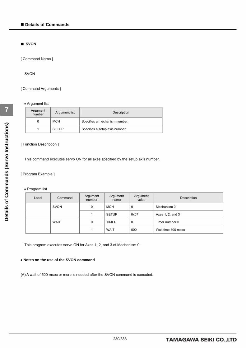
230/388
Details of Commands
7
Det
ails
of C
omm
ands
(Ser
vo In
stru
ctio
ns)
■ SVON
[ Command Name ]
SVON
[ Command Arguments ]
• Argument list
Argument number Argument list Description
0 MCH Specifies a mechanism number.
1 SETUP Specifies a setup axis number.
[ Function Description ]
This command executes servo ON for all axes specified by the setup axis number.
[ Program Example ]
• Program list
Label Command Argument number
Argument name
Argument value Description
0 MCH 0 Mechanism 0 SVON
1 SETUP 0x07 Axes 1, 2, and 3
0 TIMER 0 Timer number 0 WAIT
1 WAIT 500 Wait time 500 msec
This program executes servo ON for Axes 1, 2, and 3 of Mechanism 0.
• Notes on the use of the SVON command
(A) A wait of 500 msec or more is needed after the SVON command is executed.

231/388
Details of Commands
7
Det
ails
of C
omm
ands
(Ser
vo In
stru
ctio
ns)
■ SVOFF
[ Command Name ]
SVOFF
[ Command Arguments ]
• Argument list
Argument number Argument list Description
0 MCH Specifies a mechanism number.
1 SETUP Specifies a setup axis number.
[ Function Description ]
This command executes servo OFF for all axes specified by the setup axis number.
In general, if servo OFF is executed when a servo motor with a brake is used, the brake is applied.
For servo OFF with the brake released, use the SVFREE command.
[ Program Example ]
• Program list
Label Command Argument number
Argument name
Argument value Description
0 MCH 0 Mechanism 0 SVOFF
1 SETUP 0x07 Axes 1, 2, and 3
This program executes servo OFF for Axes 1, 2, and 3 of Mechanism 0.

232/388
Details of Commands
7
Det
ails
of C
omm
ands
(Ser
vo In
stru
ctio
ns)
■ SVFREE
[ Command Name ]
SVFREE
[ Command Arguments ]
• Argument list
Argument number Argument list Description
0 MCH Specifies a mechanism number.
1 SETUP Specifies a setup axis number.
[ Function Description ]
This command executes Servo-FREE for all axes specified by the setup axis number.
In general, if servo OFF is executed when a servo motor with a brake is used, the brake is applied.
For servo OFF with the brake released, use the SVFREE command.
[ Program Example ]
• Program list
Label Command Argument number
Argument name
Argument value Description
0 MCH 0 Mechanism 0 SVFREE
1 SETUP 0x07 Axes 1, 2, and 3
This program executes Servo-FREE for Axes 1, 2, and 3 of Mechanism 0.

233/388
Details of Commands
7
Det
ails
of C
omm
ands
(Ser
vo In
stru
ctio
ns)
■ SVMODE
[ Command Name ]
SVMODE
[ Command Arguments ]
• Argument list
Argument number Argument list Description
0 MCH Specifies a mechanism number.
1 AXIS Specifies an axis number in the mechanism.
2 MODE Specifies a control mode.
[ Function Description ]
This command sets the control mode of the specified axis. Unlike for the setup axis number, specify the number
corresponding to the axis number (i.e. 3 for Axis 3 in the mechanism, etc.). You can specify only one axis. To change the
control modes of multiple axes, repeat execution of the command as many times as required.
The MODE options are as follows:
0 : NoControl
1 : Position control mode (default)
2 : Speed control mode
3 : Torque control mode
[ Program Example ]
• Program list
Label Command Argument number
Argument name
Argument value Description
0 MCH 0 Mechanism 0
1 AXIS 3 Axis 3
SVMODE
2 MODE 2 Speed control mode
This program sets the control mode of Axis 3 in Mechanism 0 to speed control mode.

234/388
Details of Commands
7
Det
ails
of C
omm
ands
(Ser
vo In
stru
ctio
ns)
• Notes on the use of the SVMODE command
(A) The SVC forcibly sets the driver to position control mode after servo ON.
The mode must be re-set after servo ON if you use this command in speed control mode or torque control mode.
(B) Whether or not the mode can be changed while axis moving is in progress depends on the driver specifications.
(C) An axis move instruction must be executed after the servo ON processing (SVON command + simple wait) if speed
control mode or electric current control mode is changed to position control mode before axis moving is performed.
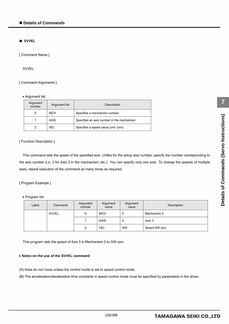
235/388
Details of Commands
7
Det
ails
of C
omm
ands
(Ser
vo In
stru
ctio
ns)
■ SVVEL
[ Command Name ]
SVVEL
[ Command Arguments ]
• Argument list
Argument number Argument list Description
0 MCH Specifies a mechanism number.
1 AXIS Specifies an axis number in the mechanism.
2 VEL Specifies a speed value (unit: rpm).
[ Function Description ]
This command sets the speed of the specified axis. Unlike for the setup axis number, specify the number corresponding to
the axis number (i.e. 3 for Axis 3 in the mechanism, etc.). You can specify only one axis. To change the speeds of multiple
axes, repeat execution of the command as many times as required.
[ Program Example ]
• Program list
Label Command Argument number
Argument name
Argument value Description
0 MCH 0 Mechanism 0
1 AXIS 3 Axis 3
SVVEL
2 VEL 500 Speed 500 rpm
This program sets the speed of Axis 3 in Mechanism 0 to 500 rpm.
• Notes on the use of the SVVEL command
(A) Axes do not move unless the control mode is set to speed control mode.
(B) The acceleration/deceleration time constants in speed control mode must be specified by parameters in the driver.

236/388
Details of Commands
7
Det
ails
of C
omm
ands
(Ser
vo In
stru
ctio
ns)
■ SVCUR
[ Command Name ]
SVCUR
[ Command Arguments ]
• Argument list
Argument number Argument list Description
0 MCH Specifies a mechanism number.
1 AXIS Specifies an axis number in the mechanism.
2 CUR Specifies an electric current value (unit:0.01 A).
[ Function Description ]
This command sets the electric current value of the specified axis. Unlike for the setup axis number, specify the number
corresponding to the axis number (i.e. 3 for Axis 3 in the mechanism, etc.). You can specify only one axis. To change the
electric current values of multiple axes, repeat execution of the command as many times as required.
[ Program Example ]
• Program list
Label Command Argument number
Argument name
Argument value Description
0 MCH 0 Mechanism 0
1 AXIS 3 Axis 3
SVCUR
2 CUR 100 Electric current value 1.0 A
This program sets the electric current value of Axis 3 in Mechanism 0 to 1.0 A.
• Notes on the use of the SVCUR command
(A) Axes do not move unless the control mode is set to electric current control mode.

237/388
Details of Commands
7
Det
ails
of C
omm
ands
(Ser
vo In
stru
ctio
ns)
■ SVPRM2
[ Command Name ]
SVPRM2
[ Command Arguments ]
• Argument list
Argument number Argument list Description
0 MCH Specifies a mechanism number.
1 AXIS Specifies an axis number in the mechanism.
2 ID Specifies the data ID to be rewritten.
3 DATA Specifies the data value to be rewritten.
[ Function Description ]
This command sets a parameter of the specified axis.
The command sends data not only to within the controller but also to the main body of the driver.
This command is invalid if a parameter cannot be rewritten effectively by specifying its parameter ID.
For more information, refer to the driver specifications.
[ Program Example ]
• Program list
Label Command Argument number
Argument name
Argument value Description
0 MCH 0 Mechanism 0
1 AXIS 3 Axis 3
2 ID 50 Data ID 50
SVPRM2
3 DATA 200 Data value 200
This program sets 200 to the value for data ID 50 of Axis 3 in Mechanism 0.

238/388
Details of Commands
7
Det
ails
of C
omm
ands
(Ser
vo In
stru
ctio
ns)

239/388
Details of Commands
7
Det
ails
of C
omm
ands
(Hom
ing
Inst
ruct
ions
)
Details of Homing Instructions

240/388
Details of Commands
7
Det
ails
of C
omm
ands
(Hom
ing
Inst
ruct
ions
)
■ HOME
[ Command Name ]
HOME
[ Command Arguments ]
• Argument list
Argument number Argument list Description
0 MCH Specifies a mechanism number.
1 SETUP Specifies a setup axis number.
2 HS1 Homing start move speed (unit of speed)
3 MS1 Home sensor LS move speed (unit of speed)
4 ZS1 Z search speed (unit of speed)
5 HMIO1 Home sensor LS DIO number
6 HMLS1 Home sensor LS number
7 LMIO Limit LS DIO number
8 LMLS1
Axis 1 is set.
Limit LS number
9 HS2 Homing start move speed (unit of speed)
10 MS2 Home sensor LS move speed (unit of speed)
11 ZS2 Z search speed (unit of speed)
12 HMIO2 Home sensor LS DIO number
13 HMLS2 Home sensor LS number
14 LMIO2 Limit LS DIO number
15 LMLS2
Axis 2 is set.
Limit LS number
: : : :
23 HS4 Homing start move speed (unit of speed)
24 MS4 Home sensor LS move speed (unit of speed)
25 ZS4 Z search speed (unit of speed)
26 HMIO4 Home sensor LS DIO number
27 HMLS4 Home sensor LS number
28 LMIO4 Limit LS DIO number
29 LMLS4
Axis 4 is set.
Limit LS number

241/388
Details of Commands
7
Det
ails
of C
omm
ands
(Hom
ing
Inst
ruct
ions
)
[ Function Description ]
This command directs homing to the driver. (A Z-phase search is performed.)
If homing is re-started after a homing operation has been completed once, the old homing information is overwritten by new
information only if the new homing operation is completed normally. The old homing information is retained until the new
homing operation is completed normally. If the new homing operation abends or aborts, the old homing information remains
intact.
[ Program Example ]
• Program list
Label Command Argument number
Argument name
Argument value Description
0 MCH 0 Mechanism 0
1 SETUP 0x05 Axes 1 and 3
2 HS1 1000 Homing start move speed 500 rpm
3 MS1 400 Home sensor LS move speed 200 rpm
4 ZS1 200 Z search speed 100 rpm
5 HMIO1 0 Home sensor LS DIO number 0
6 HMLS1 0x0001 Home sensor LS DIO number 0x0001
7 LMIO 0 Limit LS DIO number 0
8 LMLS1 0x8000
Axis 1 is set.
Limit LS number 0x8000
9 HS2 1000 Homing start move speed 500 rpm
10 MS2 400 Home sensor LS move speed 200 rpm
11 ZS2 200 Z search speed 100 rpm
12 HMIO2 1 Home sensor LS DIO number 1
13 HMLS2 0x0001 Home sensor LS DIO number 0x0001
14 LMIO2 1 Limit LS DIO number 1
HOME
15 LMLS2 0x8000
Axis 2 is set.
Limit LS number 0x8000
This program executes homing for Axes 1 and 3 of Mechanism 0.
• Notes on the use of the HOME command
(A) Servo ON processing (SVON command + simple wait time) must be executed before the HOME command.
An alarm at the task level is returned if the HOME command is executed for the axis before its servo ON processing has
been completed.

242/388
Details of Commands
7
Det
ails
of C
omm
ands
(Hom
ing
Inst
ruct
ions
)
■ HOME2
[ Command Name ]
HOME2
[ Command Arguments ]
• Argument list
Argument number Argument list Description
0 MCH Specifies a mechanism number.
1 SETUP Specifies a setup axis number.
2 HS1 Homing start move speed (unit of speed)
3 MS1 Home sensor LS move speed (unit of speed)
4 ZS1 Z search speed (unit of speed)
5 HMIO1 Home sensor LS DIO number
6 HMLS1 Home sensor LS number
7 LMIO Limit LS DIO number
8 LMLS1
Axis 1 is set.
Limit LS number
9 HS2 Homing start move speed (unit of speed)
10 MS2 Home sensor LS move speed (unit of speed)
11 ZS2 Z search speed (unit of speed)
12 HMIO2 Home sensor LS DIO number
13 HMLS2 Home sensor LS number
14 LMIO2 Limit LS DIO number
15 LMLS2
Axis 2 is set.
Limit LS number
: : : :
23 HS4 Homing start move speed (unit of speed)
24 MS4 Home sensor LS move speed (unit of speed)
25 ZS4 Z search speed (unit of speed)
26 HMIO4 Home sensor LS DIO number
27 HMLS4 Home sensor LS number
28 LMIO4 Limit LS DIO number
29 LMLS4
Axis 4 is set.
Limit LS number

243/388
Details of Commands
7
Det
ails
of C
omm
ands
(Hom
ing
Inst
ruct
ions
)
[ Function Description ]
This command directs homing to the driver. (A Z-phase search is performed.)
If homing is re-started after a homing operation has been completed once, the old homing information is overwritten by new
information only if the new homing operation is completed normally. The old homing information is retained until the new
homing operation is completed normally. If the new homing operation abends or aborts, the old homing information remains
intact.
The HOME2 command is used for a motor with two motor zero points. This type of motor uses the nearer of the two zero
points as the origin after power-on. If you execute this command for a motor with two zero points, the homing position may
differ by 180° according to the position after power-on. Use the HOME2 command for a motor that has 2 motor 0 points. [ Program Example ]
• Program list
Label Command Argument number
Argument name
Argument value Description
0 MCH 0 Mechanism 0
1 SETUP 0x05 Axes 1 and 3
2 HS1 1000 Homing start move speed 500 rpm
3 MS1 400 Home sensor LS move speed 200 rpm
4 ZS1 200 Z search speed 100 rpm
5 HMIO1 0 Home sensor LS DIO number 0
6 HMLS1 0x0001 Home sensor LS DIO number 0x0001
7 LMIO 0 Limit LS DIO number 0
8 LMLS1 0x8000
Axis 1 is set.
Limit LS number 0x8000
9 HS2 1000 Homing start move speed 500 rpm
10 MS2 400 Home sensor LS move speed 200 rpm
11 ZS2 200 Z search speed 100 rpm
12 HMIO2 1 Home sensor LS DIO number 1
13 HMLS2 0x0001 Home sensor LS DIO number 0x0001
14 LMIO2 1 Limit LS DIO number 1
HOME
15 LMLS2 0x8000
Axis 2 is set.
Limit LS number 0x8000
This program executes homing for Axes 1 and 3 of Mechanism 0.
• Notes on the use of the HOME2 command
(A) Servo ON processing (SVON command + simple wait time) must be executed before the HOME2 command.
An alarm at the task level is returned if the HOME2 command is executed for the axis before its servo ON processing
has been completed.

244/388
Details of Commands
7
Det
ails
of C
omm
ands
(Hom
ing
Inst
ruct
ions
)
■ HOMESET
[ Command Name ]
HOMESET
[ Command Arguments ]
• Argument list
Argument number Argument list Description
0 MCH Specifies a mechanism number.
1 SETUP Specifies a setup axis number.
[ Function Description ]
This command sets the origin on an ad-hoc basis.
The present position assumes 0 with the homing completed status set.
[ Program Example ]
• Program list
Label Command Argument number
Argument name
Argument value Description
0 MCH 0 Mechanism 0 HOMESET
1 SETUP 0x07 Axes 1, 2, and 3
This program sets Axes 1, 2, and 3 of Mechanism 0 to ad-hoc origins.
• Notes on the use of the HOMESET command
(A) A wait of 500 msec or more is needed after the HOMESET command is executed.
(B) The HOMESET command must be executed while the axes are stopped.

245/388
Details of Commands
7
Det
ails
of C
omm
ands
(Hom
ing
Inst
ruct
ions
)
■ HOMESET2
[ Command Name ]
HOMESET2 [ Command Arguments ]
• Argument list
Argument number Argument list Description
0 MCH Specifies a mechanism number.
1 SETUP Specifies a setup axis number.
2 PRE1 Axis 1 is set. Preset value (instruction unit)
3 PRE2 Axis 2 is set. Preset value (instruction unit)
: : : :
29 PRE28 Axis 28 is set. Preset value (instruction unit)
[ Function Description ]
This command sets the origin on an ad-hoc basis.
The present position assumes the preset value with the homing completed status set. [ Program Example ]
• Program list
Label Command Argument number
Argument name
Argument value Description
0 MCH 0 Mechanism 0
1 SETUP 0x07 Axes 1, 2, and 3
2 PRE1 1000 Preset value 1000
3 PRE2 1000 Preset value 1000
HOMESET2
4 PRE3 1000 Preset value 1000
This program sets Axes 1, 2, and 3 of Mechanism 0 to ad-hoc origins and sets their present positions to the preset value of
1000.
• Notes on the use of the HOMESET2 command
(A) A wait of 500 msec or more is needed after the HOMESET2 command is executed.
(B) The HOMESET2 command must be executed while the axes are stopped.

246/388
Details of Commands
7
Det
ails
of C
omm
ands
(Hom
ing
Inst
ruct
ions
)
■ HOMECLR
[ Command Name ]
HOMECLR
[ Command Arguments ]
• Argument list
Argument number Argument list Description
0 MCH Specifies a mechanism number.
1 SETUP Specifies a setup axis number.
[ Function Description ]
This command clears the homing completed status.
Use this command to move the machine without regard to soft limits.
This command can clear the status of only certain axes by using the setup axis number.
[ Program Example ]
• Program list
Label Command Argument number
Argument name
Argument value Description
0 MCH 0 Mechanism 0 HOMECLR
1 SETUP 0x07 Axes 1, 2, and 3
This program clears the homing completed status for Axes 1, 2, and 3 of Mechanism 0.

247/388
Details of Commands
7
Det
ails
of C
omm
ands
(Hom
ing
Inst
ruct
ions
)
■ HOMINGS
[ Command Name ]
HOMINGS
[ Command Arguments ]
• Argument list
Argument number Argument list Description
0 MCH Specifies a mechanism number.
1 SETUP Specifies a setup axis number.
[ Function Description ]
This command sets the homing in progress status.
Use this command to move the machine without regard to soft limits.
This command can set the status of only certain axes by using the setup axis number.
Unlike the HOMECLR instruction, this command can restore the homing completed status if the homing in progress status is
cleared.
[ Program Example ]
• Program list
Label Command Argument number
Argument name
Argument value Description
0 MCH 0 Mechanism 0 HOMINGS
1 SETUP 0x07 Axes 1, 2, and 3
This program sets the homing in progress status for Axes 1, 2, and 3 of Mechanism 0.

248/388
Details of Commands
7
Det
ails
of C
omm
ands
(Hom
ing
Inst
ruct
ions
)
■ HOMINGE
[ Command Name ]
HOMINGE
[ Command Arguments ]
• Argument list
Argument number Argument list Description
0 MCH Specifies a mechanism number.
1 SETUP Specifies a setup axis number.
[ Function Description ]
This command clears the homing in progress status.
This command is used after the HOMINGS command has been executed.
[ Program Example ]
• Program list
Label Command Argument number
Argument name
Argument value Description
0 MCH 0 Mechanism 0 HOMINGE
1 SETUP 0x07 Axes 1, 2, and 3
This program clears the homing in progress statuses for Axes 1, 2, and 3 of Mechanism 0.

249/388
Details of Commands
7
Det
ails
of C
omm
ands
(Hom
ing
Inst
ruct
ions
)
■ HOMEBUMP
[ Command Name ]
HOMEBUMP
[ Command Arguments ]
• Argument list
Argument number Argument list Description
0 MCH Specifies a mechanism number.
1 SETUP Specifies a setup axis number.
2 PRE1 Preset value (unit: pulse)
3 DIR1 Homing direction
0: Forward (CW) 1: Reverse (CCW)
4 VEL1 Homing speed (unit: rpm)
5 TIM1 Thrust time (unit: msec)
6 TRQ1
Axis 1 is set.
Thrust torque (unit: 0.01 A)
7 PRE2 Preset value (unit: pulse)
8 DIR2 Homing direction
0: Forward (CW) 1: Reverse (CCW)
9 VEL2 Homing speed (unit: rpm)
10 TIM2 Thrust time (unit: msec)
11 TRQ2
Axis 2 is set.
Thrust torque (unit: 0.01 A)
: : : :
22 PRE5 Preset value (unit: pulse)
23 DIR5 Homing direction
0: Forward (CW) 1: Reverse (CCW)
24 VEL5 Homing speed (unit: rpm)
25 TIM5 Thrust time (unit: msec)
26 TRQ5
Axis 5 is set.
Thrust torque (unit: 0.01 A)

250/388
Details of Commands
7
Det
ails
of C
omm
ands
(Hom
ing
Inst
ruct
ions
)
[ Function Description ]
This command directs homing to the driver. (The origin is reached by means of the mechanical stopper thrust method.)
The homing speed, thrust time, and thrust torque are executed by sending their respective parameters to the driver.
Execute servo OFF after the homing is completed. For continued operation, you must re-execute servo ON.
[ Program Example ]
• Program list
Label Command Argument number
Argument name
Argument value Description
0 MCH 0 Mechanism 0
1 SETUP 0x05 Axes 1 and 3
2 PRE1 204800 Preset value 204800 pulses
3 DIR1 0 Homing direction Forward
4 VEL1 100 Homing speed 100 rpm
5 TIM1 500 Thrust time 500 msec
6 TRQ1 100
Axis 1 is set.
Thrust torque 1.0 A
7 PRE2 204800 Preset value 204800 pulses
8 DIR2 0 Homing direction Forward
9 VEL2 100 Homing speed 100 rpm
10 TIM2 500 Thrust time 500 msec
HOMEBUMP
11 TRQ2 100
Axis 2 is set.
Thrust torque 1.0 A
This program starts homing for Axes 1 and 3 of Mechanism 0 by means of the mechanical stopper thrust method.
• Notes on the use of the HOMEBUMP command
(A) Servo ON processing (SVON command + simple wait time) must be executed before the HOMEBUMP command.
An alarm at the task level is returned if the HOMEBUMP command is executed for the axis before its servo ON
processing has been completed.
(B) With the HOMEBUMP command, servo OFF is executed after completion of homing. For continued operation of the axis,
you must re-execute servo ON (SVON command + simple wait time).
(C) The acceleration/deceleration time constants of the HOMEBUMP command must be specified by parameters in the
driver.

251/388
Details of Commands
7
Det
ails
of C
omm
ands
(Hom
ing
Inst
ruct
ions
)
■ HOMESV
[ Command Name ]
HOMESV
[ Command Arguments ]
• Argument list
Argument number Argument list Description
0 MCH Specifies a mechanism number.
1 SETUP Specifies a setup axis number.
2 TYP1 Homing Type
3 PRE1 Preset value (unit: pulse)
4 DIR1 Homing direction
0: Forward (CW) 1: Reverse (CCW)
5 VEL1 Homing speed (unit: rpm)
6 CRP1 Creep speed (unit: rpm)
7 HMIO1 DIO number
8 HMLS1
Axis 1 is set.
Origin LS number
9 TYP2 Homing Type
10 PRE2 Preset value (unit: pulse)
11 DIR2 Homing direction
0: Forward (CW) 1: Reverse (CCW)
12 VEL2 Homing speed (unit: rpm)
13 CRP2 Creep speed (unit: rpm)
14 HMIO2 DIO number
15 HMLS2
Axis 2 is set.
Origin LS number
: : : :
23 TYP4 Homing Type
24 PRE4 Preset value (unit: pulse)
25 DIR4 Homing direction
0: Forward (CW) 1: Reverse (CCW)
26 VEL4 Homing speed (unit: rpm)
27 CRP4 Creep speed (unit: rpm)
28 HMIO4 DIO number
29 HMLS4
Axis 4 is set.
Origin LS number

252/388
Details of Commands
7
Det
ails
of C
omm
ands
(Hom
ing
Inst
ruct
ions
)
[ Function Description ]
This command directs homing to the driver. (The origin is reached by means of the origin detection signal.)
The homing speed and creep speed are executed by sending their respective parameters to the driver.
The following origin detection modes are available according to Homing Type setting:
Homing Type 0 : The position is preset by the home sensor signal + motor 0 point.
2 : The axis stops immediately and the position is preset by the home sensor signal.
3 : After the home sensor signal is input, the return operation is performed and the position is preset until the
input signal is reset.
Set the origin detection signal to a DIO number and origin LS number.
Use a bit pattern for setting the origin LS number.
For example, use 0x0001 if the origin detection signal is set to DIO 0 and input by BIT_0, and use 0x0200 if the origin
detection signal is input by BIT_9. [ Program Example ]
• Program list
Label Command Argument number
Argument name
Argument value Description
0 MCH 0 Mechanism 0
1 SETUP 0x05 Axes 1 and 3
2 TYP1 2 Homing Type 2
3 PRE1 0 Preset value 0 pulses
4 DIR1 0 Homing direction Forward
5 VEL1 500 Homing speed 500 rpm
6 CRP1 100 Creep speed 100 rpm
7 HMIO1 0 Origin detection signal DIO_0
8 HMLS1 0x0001
Axis 1 is set.
Origin detection LS number BIT_0
9 TYP1 2 Homing Type 2
10 PRE1 0 Preset value 0 pulses
11 DIR1 0 Homing direction Forward
VEL1 500 Homing speed 500 rpm
CRP1 100 Creep speed 100 rpm
HMIO1 1 Origin detection signal DIO_1
HOMESV
HMLS1 0x0002
Axis 2 is set.
Origin detection LS number BIT_1
This program starts homing for Axes 1 and 3 of Mechanism 0.

253/388
Details of Commands
7
Det
ails
of C
omm
ands
(Hom
ing
Inst
ruct
ions
)
• Notes on the use of the HOMESV command
(A) Servo ON processing (SVON command + simple wait time) must be executed before the HOMESV command.
An alarm at the task level is returned if the HOMESV command is executed for the axis before its servo ON processing
has been completed.
(B) The acceleration/deceleration time constants of the HOMESV command must be specified by parameters in the driver.

254/388
Details of Commands
7
Det
ails
of C
omm
ands
(Hom
ing
Inst
ruct
ions
)

255/388
Details of Commands
7
Det
ails
of C
omm
ands
(Net
wor
k In
stru
ctio
ns)
Details of Network Instructions

256/388
Details of Commands
7
Det
ails
of C
omm
ands
(Net
wor
k In
stru
ctio
ns)
■ RUNRS
[ Command Name ]
RUNRS
[ Command Arguments ]
None
[ Function Description ]
This command starts automatic send/receive to/from the device connected to the RS232C port of the SVC.
The initial address, the number of data elements to acquire, etc. depend on the parameters of the RS232C device and
controller.
[ Program Example ]
• Program list
Label Command Argument number
Argument name
Argument value Description
RUNRS No arguments
This program starts RS232C automatic send/receive.

257/388
Details of Commands
7
Det
ails
of C
omm
ands
(Net
wor
k In
stru
ctio
ns)
■ STOPRS
[ Command Name ]
STOPRS
[ Command Arguments ]
None
[ Function Description ]
This command stops automatic send/receive to/from the device connected to the RS232C port of the SVC.
[ Program Example ]
• Program list
Label Command Argument number
Argument name
Argument value Description
STOPRS No arguments
This program stops RS232C automatic send/receive.

258/388
Details of Commands
7
Det
ails
of C
omm
ands
(Net
wor
k In
stru
ctio
ns)
■ GETRS
[ Command Name ]
GETRS
[ Command Arguments ]
• Argument list
Argument number Argument list Description
0 VAR_ADR Specifies the initial address for the data storage variable.
1 RS_ADR Specifies the initial address for the RS232C device.
2 DEV1 Specifies the device type of the RS232C device
(ASCII code at the first character position).
3 DEV2 Specifies the device type of the RS232C device
(ASCII code at the second character position).
4 NUM Specifies the number of data elements to acquire.
[ Function Description ]
This command acquires data from the device connected to the RS232C port of the SVC.
The initial address and the number of data elements to acquire depend on the specifications of the RS232C device.
[ Program Example ]
• Program list
Label Command Argument number
Argument name
Argument value Description
0 VAR_ADR &TEMP[0] Initial address of variable TEMP[0]
1 RS_ADR 0x0100 Initial address for the RS232C device
0x0100
2 DEV1 0
3 DEV2 0
GETRS
4 NUM 64 Number of data elements to acquire 64
This program acquires 64 data elements beginning with the address 0x0100 of the RS232C device and stores these data
elements in 64 members beginning with the variable TEMP[0].

259/388
Details of Commands
7
Det
ails
of C
omm
ands
(Net
wor
k In
stru
ctio
ns)
■ SETRS
[ Command Name ]
SETRS
[ Command Arguments ]
• Argument list
Argument number Argument list Description
0 VAR_ADR Specifies the initial address for the variable to which the data is set.
1 RS_ADR Specifies the initial address for the RS232C device.
2 DEV1 Specifies the device type of the RS232C device
(ASCII code at the first character position).
3 DEV2 Specifies the device type of the RS232C device
(ASCII code at the second character position).
4 NUM Specifies the number of data elements to set.
[ Function Description ]
This command sets data to the device connected to the RS232C port of the SVC.
The initial address and the number of data elements to acquire depend on the specifications of the RS232C device.
[ Program Example ]
• Program list
Label Command Argument number
Argument name
Argument value Description
0 VAR_ADR &TEMP[0] Initial address of variable TEMP[0]
1 RS_ADR 0x0100 Initial address for the RS232C device
0x0100
2 DEV1 0
3 DEV2 0
SETRS
4 NUM 64 Number of data elements to set 64
This program acquires 64 data elements beginning with the variable TEMP[0] and stores these data elements in 64
locations beginning with the address 0x0100 of the RS232C device.

260/388
Details of Commands
7
Det
ails
of C
omm
ands
(Net
wor
k In
stru
ctio
ns)
■ FINRS
[ Command Name ]
FINRS
[ Command Arguments ]
None
[ Function Description ]
This command places the program in a wait status at the current index until the RS command (GETRS or SETRS) has
been completed.
[ Program Example ]
• Program list
Label Command Argument number
Argument name
Argument value Description
FINRS No arguments
This program waits at the current index until the RS command (GETRS or SETRS) has been completed.

261/388
Details of Commands
7
Det
ails
of C
omm
ands
(JO
G In
stru
ctio
ns)
Details of JOG Instructions
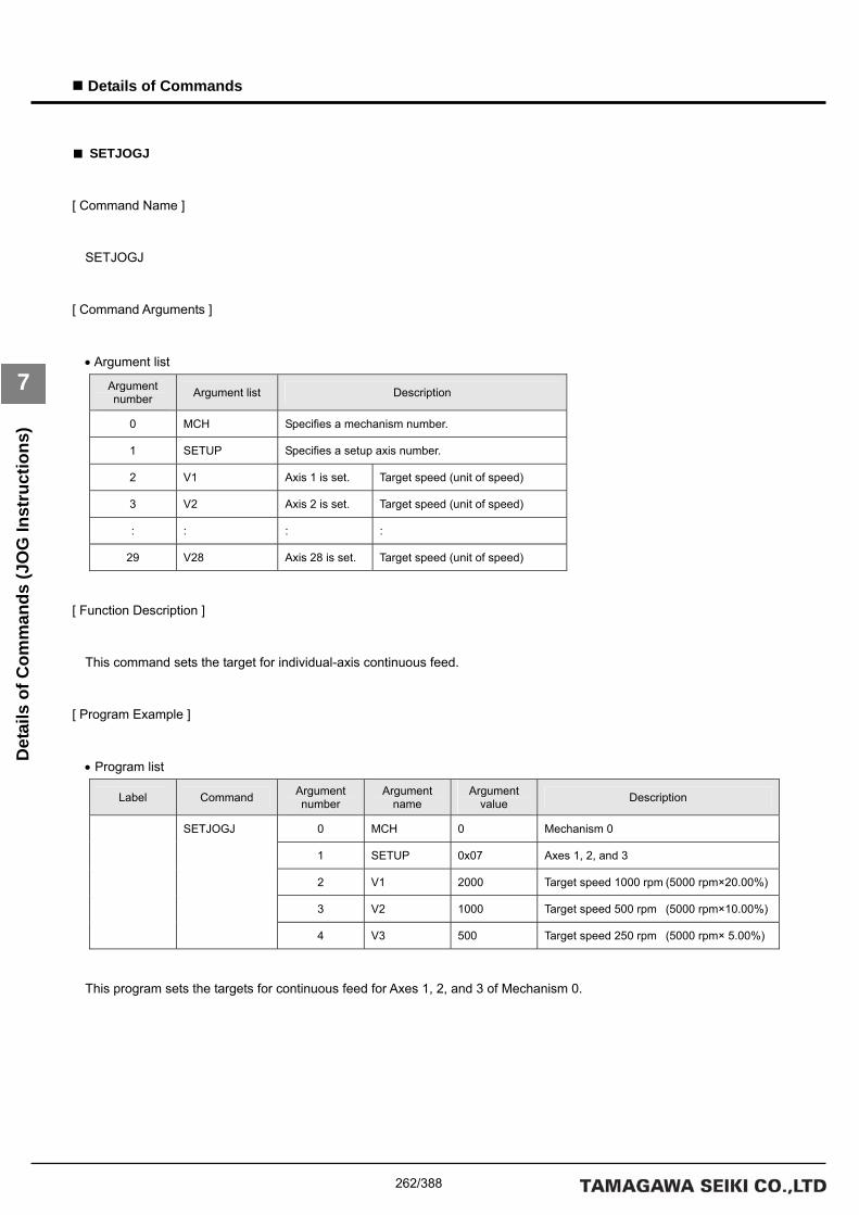
262/388
Details of Commands
7
Det
ails
of C
omm
ands
(JO
G In
stru
ctio
ns)
■ SETJOGJ
[ Command Name ]
SETJOGJ
[ Command Arguments ]
• Argument list
Argument number Argument list Description
0 MCH Specifies a mechanism number.
1 SETUP Specifies a setup axis number.
2 V1 Axis 1 is set. Target speed (unit of speed)
3 V2 Axis 2 is set. Target speed (unit of speed)
: : : :
29 V28 Axis 28 is set. Target speed (unit of speed)
[ Function Description ]
This command sets the target for individual-axis continuous feed.
[ Program Example ]
• Program list
Label Command Argument number
Argument name
Argument value Description
0 MCH 0 Mechanism 0
1 SETUP 0x07 Axes 1, 2, and 3
2 V1 2000 Target speed 1000 rpm (5000 rpm×20.00%)
3 V2 1000 Target speed 500 rpm (5000 rpm×10.00%)
SETJOGJ
4 V3 500 Target speed 250 rpm (5000 rpm× 5.00%)
This program sets the targets for continuous feed for Axes 1, 2, and 3 of Mechanism 0.

263/388
Details of Commands
7
Det
ails
of C
omm
ands
(JO
G In
stru
ctio
ns)
■ JOGJ
[ Command Name ]
JOGJ
[ Command Arguments ]
• Argument list
Argument number Argument list Description
0 MCH Specifies a mechanism number.
1 SETUP Specifies a setup axis number.
2 V1 Axis 1 is set. Target speed (unit of speed)
3 V2 Axis 2 is set. Target speed (unit of speed)
: : : :
29 V28 Axis 28 is set. Target speed (unit of speed)
[ Function Description ]
This command performs individual-axis continuous feeds.
[ Program Example ]
• Program list
Label Command Argument number
Argument name
Argument value Description
0 MCH 0 Mechanism 0
1 SETUP 0x07 Axes 1, 2, and 3
2 V1 2000 Speed 1000 rpm (5000 rpm×20.00%)
3 V2 1000 Speed 500 rpm (5000 rpm×10.00%)
JOGJ
4 V3 500 Speed 250 rpm (5000 rpm× 5.00%)
This program performs continuous feed for Axes 1, 2, and 3 of Mechanism 0.

264/388
Details of Commands
7
Det
ails
of C
omm
ands
(JO
G In
stru
ctio
ns)

265/388
Details of Commands
7
Det
ails
of C
omm
ands
(Abs
olut
e Po
sitio
n M
ove
Targ
et S
et In
stru
ctio
ns)
Details of Absolute Position Move Target Set Instructions
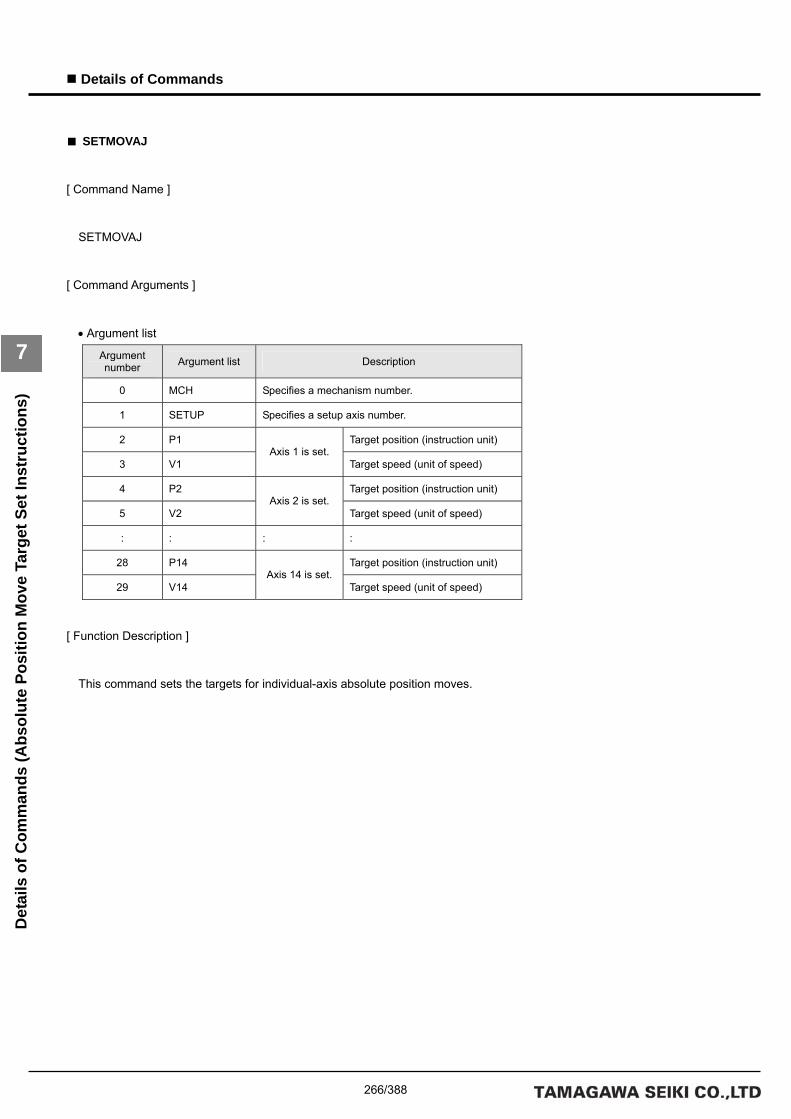
266/388
Details of Commands
7
Det
ails
of C
omm
ands
(Abs
olut
e Po
sitio
n M
ove
Targ
et S
et In
stru
ctio
ns)
■ SETMOVAJ
[ Command Name ]
SETMOVAJ
[ Command Arguments ]
• Argument list
Argument number Argument list Description
0 MCH Specifies a mechanism number.
1 SETUP Specifies a setup axis number.
2 P1 Target position (instruction unit)
3 V1 Axis 1 is set.
Target speed (unit of speed)
4 P2 Target position (instruction unit)
5 V2 Axis 2 is set.
Target speed (unit of speed)
: : : :
28 P14 Target position (instruction unit)
29 V14 Axis 14 is set.
Target speed (unit of speed)
[ Function Description ]
This command sets the targets for individual-axis absolute position moves.

267/388
Details of Commands
7
Det
ails
of C
omm
ands
(Abs
olut
e Po
sitio
n M
ove
Targ
et S
et In
stru
ctio
ns)
[ Program Example ]
• Program list
Label Command Argument number
Argument name
Argument value Description
0 MCH 0 Mechanism 0
1 SETUP 0x03 Axes 1 and 2
2 P1 1000 Target position 100.0 mm
3 V1 2000 Target speed 1000 rpm (5000 rpm×20.00%)
4 P2 1000 Target position 100.0 mm
SETMOVAJ
5 V2 2000 Target speed 1000 rpm (5000 rpm×20.00%)
: : : : :
0 MCH 0 Mechanism 0 MOVE
1 SETUP 0x03 Axes 1 and 2
This program sets the targets for individual-axis absolute position moves for Axes 1 and 2 of Mechanism 0.
The move is started by a MOVE command.
[ Move Example ]
The figure below shows an example of a move from the present position (20, 20) to the target position with Axis 1 as the X
axis and Axis 2 as the Y axis.
If the same acceleration/deceleration time constant is set for the X and Y axes, a linear interpolation move is performed.
Coordinate origin (0, 0)
Move to the target position (100, 100).
Y axis (Axis 2)
X axis (Axis 1)
Present position (20, 20)
1000rpm
Time
Speed
Time
Speed
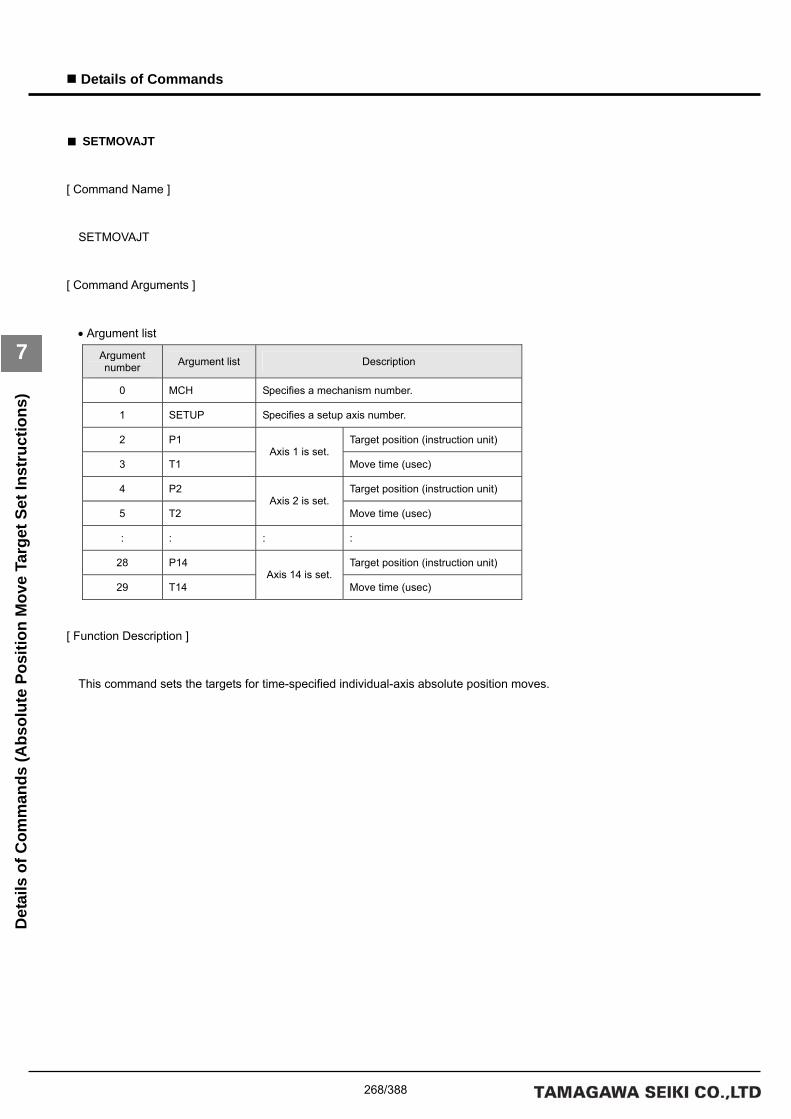
268/388
Details of Commands
7
Det
ails
of C
omm
ands
(Abs
olut
e Po
sitio
n M
ove
Targ
et S
et In
stru
ctio
ns)
■ SETMOVAJT
[ Command Name ]
SETMOVAJT
[ Command Arguments ]
• Argument list
Argument number Argument list Description
0 MCH Specifies a mechanism number.
1 SETUP Specifies a setup axis number.
2 P1 Target position (instruction unit)
3 T1 Axis 1 is set.
Move time (usec)
4 P2 Target position (instruction unit)
5 T2 Axis 2 is set.
Move time (usec)
: : : :
28 P14 Target position (instruction unit)
29 T14 Axis 14 is set.
Move time (usec)
[ Function Description ]
This command sets the targets for time-specified individual-axis absolute position moves.

269/388
Details of Commands
7
Det
ails
of C
omm
ands
(Abs
olut
e Po
sitio
n M
ove
Targ
et S
et In
stru
ctio
ns)
[ Program Example ]
• Program list
Label Command Argument number
Argument name
Argument value Description
0 MCH 0 Mechanism 0
1 SETUP 0x01 Axis 1
2 P1 1000 Target position 100.0 mm
SETMOVAJT
3 T1 1000000 Move time 1.0 sec
: : : : :
0 MCH 0 Mechanism 0 MOVE
1 SETUP 0x01 Axis 1
This program sets the target for a time-specified individual-axis absolute position move for Axis 1 of Mechanism 0.
The move is started by a MOVE command.
[ Move Example ]
The figure below shows an example of a time-specified individual-axis absolute position move. Speeds are calculated
automatically by position and time.
The target time is the time period up to the completion of interpolation calculation. If an acceleration/deceleration time
constant is set, the move time is extended by the set time.

270/388
Details of Commands
7
Det
ails
of C
omm
ands
(Abs
olut
e Po
sitio
n M
ove
Targ
et S
et In
stru
ctio
ns)
■ SETMOVAJFS
[ Command Name ]
SETMOVAJFS
[ Command Arguments ]
• Argument list
Argument number Argument list Description
0 MCH Specifies a mechanism number.
1 SETUP Specifies a setup axis number.
2 P1 Target position (instruction unit)
3 S1 Target initial speed (unit of speed)
4 E1
Axis 1 is set.
Target end speed (unit of speed)
5 P2 Target position (instruction unit)
6 S2 Target initial speed (unit of speed)
7 E2
Axis 2 is set.
Target end speed (unit of speed)
: : : :
26 P9 Target position (instruction unit)
27 S9 Target initial speed (unit of speed)
28 E9
Axis 9 is set.
Target end speed (unit of speed)
[ Function Description ]
This command sets the targets for primary-speed individual-axis absolute position moves.
• Notes on the use of the SETMOVAJFS command
(A) To use a compound move command, set the correct values for the initial speed and the end speed.
(B) If a smooth move is not obtained for the initial-to-end speed transition between move commands, review the initial
speed value and the end speed value.

271/388
Details of Commands
7
Det
ails
of C
omm
ands
(Abs
olut
e Po
sitio
n M
ove
Targ
et S
et In
stru
ctio
ns)
[ Program Example ]
• Program list
Label Command Argument number
Argument name
Argument value Description
0 MCH 0 Mechanism 0
1 SETUP 0x01 Axis 1
2 P1 500 Target position 50.0 mm
3 S1 0 Target initial speed 0 rpm
(5000 rpm×00.00%)
SETMOVAJFS
4 E1 2000 Target end speed 1000 rpm
(5000 rpm×20.00%)
: : : : :
0 MCH 0 Mechanism 0 MOVE
1 SETUP 0x01 Axis 1
This program sets the target for a primary-speed individual-axis absolute position move for Axis 1 of Mechanism 0.
The move is started by a MOVE command.
[ Move Example ]
The figure below shows an example of a primary-speed individual-axis absolute position move. Give the target initial speed
and the target end speed by arguments. This command is usually combined with multiple move commands to make a
compound move command.

272/388
Details of Commands
7
Det
ails
of C
omm
ands
(Abs
olut
e Po
sitio
n M
ove
Targ
et S
et In
stru
ctio
ns)
■ SETMOVAJCU
[ Command Name ]
SETMOVAJCU
[ Command Arguments ]
• Argument list
Argument number Argument list Description
0 MCH Specifies a mechanism number.
1 SETUP Specifies a setup axis number.
2 P1 Target position (instruction unit)
3 S1 Target initial speed (unit of speed)
4 E1 Target end speed (unit of speed)
5 T1
Axis 1 is set.
Move time (usec)
6 P2 Target position (instruction unit)
7 S2 Target initial speed (unit of speed)
8 E2 Target end speed (unit of speed)
9 T2
Axis 2 is set.
Move time (usec)
: : :
26 P7 Target position (instruction unit)
27 S7 Target initial speed (unit of speed)
28 E7 Target end speed (unit of speed)
29 T7
Axis 7 is set.
Move time (usec)
[ Function Description ]
This command sets the targets for secondary-speed individual-axis absolute position moves.
• Notes on the use of the SETMOVAJCU command
(A) To use a compound move command, set the correct values for the initial speed and the end speed.
(B) If a smooth move is not obtained for the initial-to-end speed transition between move commands, review the initial
speed value and the end speed value.
(C) When using the JCU command, check the speed data by means of the monitor function after the program is created.
If improper time values are specified, the speed will overshoot and then undershoot (reverse rotation followed by
forward rotation).

273/388
Details of Commands
7
Det
ails
of C
omm
ands
(Abs
olut
e Po
sitio
n M
ove
Targ
et S
et In
stru
ctio
ns)
[ Program Example ]
• Program list
Label Command Argument number
Argument name
Argument value Description
0 MCH 0 Mechanism 0
1 SETUP 0x01 Axis 1
2 P1 500 Target position 50.0 mm
3 S1 0 Target initial speed
0 rpm
(5000 rpm×00.00%)
4 E1 2000 Target end speed
1000 rpm
(5000 rpm×20.00%)
SETMOVAJCU
5 T1 500000 Move time 500 msec
: : : : :
0 MCH 0 Mechanism 0 MOVE
1 SETUP 0x01 Axis 1
This program sets the target for a secondary-speed individual-axis absolute position move for Axis 1 of Mechanism 0.
The move is started by a MOVE command.
[ Move Example ]
The figure below shows an example of a secondary-speed individual-axis absolute position move. Give the move time,
target initial speed, and target end speed by arguments. This command is usually combined with multiple move commands to
make a compound move command.

274/388
Details of Commands
7
Det
ails
of C
omm
ands
(Abs
olut
e Po
sitio
n M
ove
Targ
et S
et In
stru
ctio
ns)
■ SETMOVAJTW
[ Command Name ]
SETMOVAJTW
[ Command Arguments ]
• Argument list
Argument number Argument list Description
0 MCH Specifies a mechanism number.
1 SETUP Specifies a setup axis number.
2 P1 Target position (instruction unit)
3 T1 Axis 1 is set.
Move time (usec)
4 P2 Target position (instruction unit)
5 T2 Axis 2 is set.
Move time (usec)
: : : :
28 P14 Target position (instruction unit)
29 T14 Axis 14 is set.
Move time (usec)
[ Function Description ]
This command sets the targets for wait-type time-specified individual-axis absolute position moves.
Unlike the SETMOVAJT command, this command places the program in the interpolation calculation in progress status until
the specified move period has elapsed even if the move distance is 0.

275/388
Details of Commands
7
Det
ails
of C
omm
ands
(Abs
olut
e Po
sitio
n M
ove
Targ
et S
et In
stru
ctio
ns)
[ Program Example ]
• Program list
Label Command Argument number
Argument name
Argument value Description
0 MCH 0 Mechanism 0
1 SETUP 0x01 Axis 1
2 P1 1000 Target position 100.0 mm
SETMOVAJTW
3 V1 1000000 Move time 1.0 sec
: : : : :
0 MCH 0 Mechanism 0 MOVE
1 SETUP 0x01 Axis 1
This program sets the target for a wait-type time-specified individual-axis absolute position move for Axis 1 of Mechanism
0.
The move is started by a MOVE command.
[ Move Example ]
The figure below shows an example of a wait-type time-specified individual-axis absolute position move. Speeds are
calculated automatically by position and time.
The target time is the time period up to the completion of interpolation calculation. If an acceleration/deceleration time
constant is set, the move time is extended by the set time.

276/388
Details of Commands
7
Det
ails
of C
omm
ands
(Abs
olut
e Po
sitio
n M
ove
Targ
et S
et In
stru
ctio
ns)
■ SETMOVAJA1
[ Command Name ]
SETMOVAJA1
[ Command Arguments ]
• Argument list
Argument number Argument list Description
0 MCH Specifies a mechanism number.
1 SETUP Specifies a setup axis number.
2 P1 Target position (instruction unit)
3 V1 Target speed (unit of speed)
4 M1
Axis 1 is set.
Mode
5 P2 Target position (instruction unit)
6 V2 Target speed (unit of speed)
7 M2
Axis 2 is set.
Mode
: : : :
26 P9 Target position (instruction unit)
27 V9 Target speed (unit of speed)
28 M9
Axis 9 is set.
Mode
[ Function Description ]
This command sets the targets for right angle arc interpolation individual-axis absolute position moves (90-degree arc
interpolation).
The following modes are available:
1 = X axis
0 = Synchronous axes (Z, Θ, etc.)
-1 = Y axis
• Notes on the use of the SETMOVAJA1 command
(A) To make the arc a perfect circle, specify the correct target position argument with respect to the present position.
The SVC determines the center coordinates of the arc based on the present position and the target position.

277/388
Details of Commands
7
Det
ails
of C
omm
ands
(Abs
olut
e Po
sitio
n M
ove
Targ
et S
et In
stru
ctio
ns)
[ Program Example ]
• Program list
Label Command Argument number
Argument name
Argument value Description
0 MCH 0 Mechanism 0
1 SETUP 0x03 Axes 1 and 2
2 P1 1000 Target position 100.0 mm
3 V1 2000 Target speed 1000 rpm (5000 rpm×20.00%)
4 M1 1 Mode X axis
5 P2 1000 Target position 100.0 mm
6 V2 2000 Target speed 1000 rpm (5000 rpm×20.00%)
SETMOVAJA1
7 M2 -1 Mode Y axis
: : : : :
0 MCH 0 Mechanism 0 MOVE
1 SETUP 0x03 Axes 1 and 2
This program sets the targets for right angle arc interpolation individual-axis absolute position moves for Axes 1 and 2 of
Mechanism 0.
The move is started by a MOVE command.
[ Move Example ]
The figure below shows an example of a right angle arc interpolation individual-axis absolute position move. The present
position is at the origin (0, 0) of the coordinate system.
100.0mm
Y axis
Center
X axis
Coordinate origin (0, 0)

278/388
Details of Commands
7
Det
ails
of C
omm
ands
(Abs
olut
e Po
sitio
n M
ove
Targ
et S
et In
stru
ctio
ns)
■ SETMOVAJA2
[ Command Name ]
SETMOVAJA2
[ Command Arguments ]
• Argument list
Argument number Argument list Description
0 MCH Specifies a mechanism number.
1 SETUP Specifies a setup axis number.
2 P1 Target position (instruction unit)
3 V1 Target speed (unit of speed)
4 M1 Mode
5 O1
Axis 1 is set.
Auxiliary data (center or angle)
6 P2 Target position (instruction unit)
7 V2 Target speed (unit of speed)
8 M2 Mode
9 O2
Axis 2 is set.
Auxiliary data (center or angle)
: : : :
26 P7 Target position (instruction unit)
27 V7 Target speed (unit of speed)
28 M7 Mode
29 O7
Axis 7 is set.
Auxiliary data (center or angle)
[ Function Description ]
This command sets the targets for arc interpolation individual-axis absolute position moves. The following modes are
available for arc interpolation:
3 = X axis (center specified, CCW rotation)
2 = X axis (center specified, CW rotation)
1 = X axis (start point angle and end point angle specified)
0 = Synchronous axes (Z, Θ, etc.)
-1 = Y axis
• Notes on the use of the SETMOVAJA2 command
(A) To make the arc a perfect circle, specify the correct coordinates for the center.

279/388
Details of Commands
7
Det
ails
of C
omm
ands
(Abs
olut
e Po
sitio
n M
ove
Targ
et S
et In
stru
ctio
ns)
[ Program Example ]
• Program list
Label Command Argument number
Argument name
Argument value Description
0 MCH 0 Mechanism 0
1 SETUP 0x03 Axes 1 and 2
2 P1 200 Target position 20.0 mm
3 V1 2000 Target speed 1000 rpm (5000 rpm×20.00%)
4 M1 2 Mode X axis Center specified, CW rotation
5 O1 400 Coordinates of the center 40.0 mm
6 P2 600 Target position 60.0 mm
7 V2 2000 Target speed 1000 rpm (5000 rpm×20.00%)
8 M2 -1 Mode Y axis
SETMOVAJA2
9 O2 0 Coordinates of the center 0.0 mm
: : : : :
0 MCH 0 Mechanism 0 MOVE
1 SETUP 0x03 Axes 1 and 2
This program sets the targets for arc interpolation individual-axis absolute position moves for Axes 1 and 2 of Mechanism 0.
The move is started by a MOVE command.
[ Move Example ]
The figure below shows an example of an arc interpolation individual-axis absolute position move. The present position is
at the coordinates (20, 60).
Present position (20, 60)
Y axis
R 40.0mm
Coordinates of the center (60, 60)
X axis
Coordinate origin (0, 0)

280/388
Details of Commands
7
Det
ails
of C
omm
ands
(Abs
olut
e Po
sitio
n M
ove
Targ
et S
et In
stru
ctio
ns)
■ SETMOVAJBL
[ Command Name ]
SETMOVAJBL [ Command Arguments ]
• Argument list
Argument number Argument list Description
0 MCH Specifies a mechanism number.
1 SETUP Specifies a setup axis number.
2 P1 Target position (instruction unit)
3 S1 Target initial speed (unit of speed)
4 E1 Target end speed (unit of speed)
5 A1 Acceleration factor 1 (0.0001%)
6 B1
Axis 1 is set.
Acceleration factor 2 (0.0001%)
7 P2 Target position (instruction unit)
8 S2 Target initial speed (unit of speed)
9 E2 Target end speed (unit of speed)
10 A2 Acceleration factor 1 (0.0001%)
11 B2
Axis 2 is set.
Acceleration factor 2 (0.0001%)
: : : :
22 P5 Target position (instruction unit)
23 S5 Target initial speed (unit of speed)
24 E5 Target end speed (unit of speed)
25 A5 Acceleration factor 1 (0.0001%)
26 B5
Axis 5 is set.
Acceleration factor 2 (0.0001%)
[ Function Description ]
This command sets the targets for tertiary-speed individual-axis absolute position moves.
If acceleration factors 1 and 2 are set to 100%, acceleration is made constant (linear move).
• Notes on the use of the SETMOVAJBL command
(A) To use a compound move command, set the correct values for the initial speed and the end speed.
(B) If a smooth move is not obtained for the initial-to-end speed transition between move commands, review the initial
speed value and the end speed value.

281/388
Details of Commands
7
Det
ails
of C
omm
ands
(Abs
olut
e Po
sitio
n M
ove
Targ
et S
et In
stru
ctio
ns)
[ Program Example ]
• Program list
Label Command Argument number
Argument name
Argument value Description
0 MCH 0 Mechanism 0
1 SETUP 0x01 Axis 1
2 P1 1000 Target position 100.0 mm
3 S1 0 Target initial speed 0 rpm (5000 rpm×00.00%)
4 E1 2000 Target end speed 1000 rpm (5000 rpm×20.00%)
5 A1 0 Acceleration factor 1 0.000%
SETMOVAJBL
6 B1 0 Acceleration factor 2 0.000%
: : : : :
0 MCH 0 Mechanism 0 MOVE
1 SETUP 0x01 Axis 1
This program sets the target for a tertiary-speed individual-axis absolute position move for Axis 1 of Mechanism 0.
The move is started by a MOVE command.
[ Move Example 1 ]
The figure below shows examples of tertiary-speed individual-axis absolute position moves. It shows a move with
acceleration factors 1 and 2 both set to 0%, another move with them both set to 50%, and another move with them both set to
100%.
MOVJBL command
Time
Speed
Target initial speed (0rpm)
Target end speed (1000rpm)
Acceleration factor 1=100.0% Acceleration factor 2=100.0%
Acceleration factor 1=50.0% Acceleration factor 2=50.0%
Acceleration factor 1=0.0% Acceleration factor 2=0.0%

282/388
Details of Commands
7
Det
ails
of C
omm
ands
(Abs
olut
e Po
sitio
n M
ove
Targ
et S
et In
stru
ctio
ns)
[ Move Example 2 ]
The figure below shows examples of tertiary-speed individual-axis absolute position moves. It shows a move with
acceleration factors 1 and 2 set individually to either 0% or 100% in the combinations indicated.

283/388
Details of Commands
7
Det
ails
of C
omm
ands
(Rel
ativ
e Po
sitio
n M
ove
Targ
et S
et In
stru
ctio
ns)
Details of Relative Position Move Target Set Instructions

284/388
Details of Commands
7
Det
ails
of C
omm
ands
(Rel
ativ
e Po
sitio
n M
ove
Targ
et S
et In
stru
ctio
ns)
■ SETMOVIJ
[ Command Name ]
SETMOVIJ
[ Command Arguments ]
• Argument list
Argument number Argument list Description
0 MCH Specifies a mechanism number.
1 SETUP Specifies a setup axis number.
2 P1 Target distance (instruction unit)
3 V1 Axis 1 is set.
Target speed (unit of speed)
4 P2 Target distance (instruction unit)
5 V2 Axis 2 is set.
Target speed (unit of speed)
: : : :
28 P14 Target distance (instruction unit)
29 V14 Axis 14 is set.
Target speed (unit of speed)
[ Function Description ]
This command sets the targets for individual-axis relative position moves.

285/388
Details of Commands
7
Det
ails
of C
omm
ands
(Rel
ativ
e Po
sitio
n M
ove
Targ
et S
et In
stru
ctio
ns)
[ Program Example ]
• Program list
Label Command Argument number
Argument name
Argument value Description
0 MCH 0 Mechanism 0
1 SETUP 0x03 Axes 1 and 2
2 P1 800 Target distance 80.0 mm
3 V1 2000 Target speed 1000 rpm (5000 rpm×20.00%)
4 P2 800 Target distance 80.0 mm
SETMOVIJ
5 V2 2000 Target speed 1000 rpm (5000 rpm×20.00%)
: : : : :
0 MCH 0 Mechanism 0 MOVE
1 SETUP 0x03 Axes 1 and 2
This program sets the target for individual-axis relative position moves for Axes 1 and 2 of Mechanism 0.
The move is started by a MOVE command.
[ Move Example ]
The figure below shows an example of a move by the target distance from the present position (20, 20) with Axis 1 as the X
axis and Axis 2 as the Y axis.
If the same acceleration/deceleration time constant is set for the X and Y axes, a linear interpolation move is performed.
Coordinate origin (0, 0)
Move to the target position (100, 100).
Y axis (Axis 2)
X axis (Axis 1)
Present position (20, 20)
1000rpm
Time
Speed
Time
Speed

286/388
Details of Commands
7
Det
ails
of C
omm
ands
(Rel
ativ
e Po
sitio
n M
ove
Targ
et S
et In
stru
ctio
ns)
■ SETMOVIJT
[ Command Name ]
SETMOVIJT
[ Command Arguments ]
• Argument list
Argument number Argument list Description
0 MCH Specifies a mechanism number.
1 SETUP Specifies a setup axis number.
2 P1 Target distance (instruction unit)
3 T1 Axis 1 is set.
Move time (usec)
4 P2 Target distance (instruction unit)
5 T2 Axis 2 is set.
Move time (usec)
: : : :
28 P14 Target distance (instruction unit)
29 T14 Axis 14 is set.
Move time (usec)
[ Function Description ]
This command sets the targets for time-specified individual-axis relative position moves.

287/388
Details of Commands
7
Det
ails
of C
omm
ands
(Rel
ativ
e Po
sitio
n M
ove
Targ
et S
et In
stru
ctio
ns)
[ Program Example ]
• Program list
Label Command Argument number
Argument name
Argument value Description
0 MCH 0 Mechanism 0
1 SETUP 0x01 Axis 1
2 P1 1000 Target distance 100.0 mm
SETMOVIJT
3 T1 1000000 Move time 1.0 sec
: : : : :
0 MCH 0 Mechanism 0 MOVE
1 SETUP 0x01 Axis 1
This program sets the target for a time-specified individual-axis relative position move for Axis 1 of Mechanism 0.
The move is started by a MOVE command.
[ Move Example ]
The figure below shows an example of a time-specified individual-axis relative position move. Speeds are calculated
automatically by position and time.
The target time is the time period up to the completion of interpolation calculation. If an acceleration/deceleration time
constant is set, the move time is extended by the set time.

288/388
Details of Commands
7
Det
ails
of C
omm
ands
(Rel
ativ
e Po
sitio
n M
ove
Targ
et S
et In
stru
ctio
ns)
■ SETMOVIJFS
[ Command Name ]
SETMOVIJFS
[ Command Arguments ]
• Argument list
Argument number Argument list Description
0 MCH Specifies a mechanism number.
1 SETUP Specifies a setup axis number.
2 P1 Target distance (instruction unit)
3 S1 Target initial speed (unit of speed)
4 E1
Axis 1 is set.
Target end speed (unit of speed)
5 P2 Target distance (instruction unit)
6 S2 Target initial speed (unit of speed)
7 E2
Axis 2 is set.
Target end speed (unit of speed)
: : : :
26 P9 Target distance (instruction unit)
27 S9 Target initial speed (unit of speed)
28 E9
Axis 9 is set.
Target end speed (unit of speed)
[ Function Description ]
This command sets the targets for primary-speed individual-axis relative position moves.
• Notes on the use of the SETMOVIJFS command
(A) To use a compound move command, set the correct values for the initial speed and the end speed.
(B) If a smooth move is not obtained for the initial-to-end speed transition between move commands, review the initial
speed value and the end speed value.

289/388
Details of Commands
7
Det
ails
of C
omm
ands
(Rel
ativ
e Po
sitio
n M
ove
Targ
et S
et In
stru
ctio
ns)
[ Program Example ]
• Program list
Label Command Argument number
Argument name
Argument value Description
0 MCH 0 Mechanism 0
1 SETUP 0x01 Axis 1
2 P1 500 Target distance 50.0 mm
3 S1 0 Target initial speed 0 rpm
(5000 rpm×00.00%)
SETMOVIJFS
4 E1 2000 Target end speed 1000 rpm
(5000 rpm×20.00%)
: : : : :
0 MCH 0 Mechanism 0 MOVE
1 SETUP 0x01 Axis 1
This program sets the target for a primary-speed individual-axis relative position move for Axis 1 of Mechanism 0.
The move is started by a MOVE command.
[ Move Example ]
The figure below shows an example of a primary-speed individual-axis relative position move. Give the target initial speed
and the target end speed by arguments. This command is usually combined with multiple move commands to make a
compound move command.

290/388
Details of Commands
7
Det
ails
of C
omm
ands
(Rel
ativ
e Po
sitio
n M
ove
Targ
et S
et In
stru
ctio
ns)
■ SETMOVIJCU
[ Command Name ]
SETMOVIJCU
[ Command Arguments ]
• Argument list
Argument number Argument list Description
0 MCH Specifies a mechanism number.
1 SETUP Specifies a setup axis number.
2 P1 Target distance (instruction unit)
3 S1 Target initial speed (unit of speed)
4 E1 Target end speed (unit of speed)
5 T1
Axis 1 is set.
Move time (usec)
6 P2 Target distance (instruction unit)
7 S2 Target initial speed (unit of speed)
8 E2 Target end speed (unit of speed)
9 T2
Axis 2 is set.
Move time (usec)
: : :
26 P7 Target distance (instruction unit)
27 S7 Target initial speed (unit of speed)
28 E7 Target end speed (unit of speed)
29 T7
Axis 7 is set.
Move time (usec)
[ Function Description ]
This command sets the targets for secondary-speed individual-axis relative position moves.
• Notes on the use of the SETMOVIJCU command
(A) To use a compound move command, set the correct values for the initial speed and the end speed.
(B) If a smooth move is not obtained for the initial-to-end speed transition between move commands, review the initial
speed value and the end speed value.
(C) When using the JCU command, check the speed data by means of the monitor function after the program is created.
If improper time values are specified, the speed will overshoot and then undershoot (reverse rotation followed by
forward rotation).

291/388
Details of Commands
7
Det
ails
of C
omm
ands
(Rel
ativ
e Po
sitio
n M
ove
Targ
et S
et In
stru
ctio
ns)
[ Program Example ]
• Program list
Label Command Argument number
Argument name
Argument value Description
0 MCH 0 Mechanism 0
1 SETUP 0x01 Axis 1
2 P1 500 Target distance 50.0 mm
3 S1 0 Target initial speed 0 rpm
(5000 rpm×00.00%)
4 E1 2000 Target end speed 1000 rpm
(5000 rpm×20.00%)
SETMOVIJCU
5 T1 500000 Move time 500 msec
: : : : :
0 MCH 0 Mechanism 0 MOVE
1 SETUP 0x01 Axis 1
This program sets the target for a secondary-speed individual-axis relative position move for Axis 1 of Mechanism 0.
The move is started by a MOVE command.
[ Move Example ]
The figure below shows an example of a secondary-speed individual-axis relative position move. Give the move time,
target initial speed, and target end speed by arguments. This command is usually combined with multiple move commands to
make a compound move command.

292/388
Details of Commands
7
Det
ails
of C
omm
ands
(Rel
ativ
e Po
sitio
n M
ove
Targ
et S
et In
stru
ctio
ns)
■ SETMOVIJTW
[ Command Name ]
SETMOVIJTW
[ Command Arguments ]
• Argument list
Argument number Argument list Description
0 MCH Specifies a mechanism number.
1 SETUP Specifies a setup axis number.
2 P1 Target distance (instruction unit)
3 T1 Axis 1 is set.
Move time (usec)
4 P2 Target distance (instruction unit)
5 T2 Axis 2 is set.
Move time (usec)
: : : :
28 P14 Target distance (instruction unit)
29 T14 Axis 14 is set.
Move time (usec)
[ Function Description ]
This command sets the targets for wait-type time-specified individual-axis relative position moves.
Unlike the SETMOVIJT command, this command places the program in the interpolation calculation in progress status until
the specified move period has elapsed even if the move distance is 0.

293/388
Details of Commands
7
Det
ails
of C
omm
ands
(Rel
ativ
e Po
sitio
n M
ove
Targ
et S
et In
stru
ctio
ns)
[ Program Example ]
• Program list
Label Command Argument number
Argument name
Argument value Description
0 MCH 0 Mechanism 0
1 SETUP 0x01 Axis 1
2 P1 1000 Target distance 100.0 mm
SETMOVIJTW
3 V1 1000000 Move time 1.0 sec
: : : : :
0 MCH 0 Mechanism 0 MOVE
1 SETUP 0x01 Axis 1
This program sets the target for a wait-type time-specified individual-axis relative position move for Axis 1 of Mechanism 0.
The move is started by a MOVE command.
[ Move Example ]
The figure below shows an example of a wait-type time-specified individual-axis relative position move. Speeds are
calculated automatically by position and time.
The target time is the time period up to the completion of interpolation calculation. If an acceleration/deceleration time
constant is set, the move time is extended by the set time.

294/388
Details of Commands
7
Det
ails
of C
omm
ands
(Rel
ativ
e Po
sitio
n M
ove
Targ
et S
et In
stru
ctio
ns)
■ SETMOVIJA1
[ Command Name ]
SETMOVIJA1
[ Command Arguments ]
• Argument list
Argument number Argument list Description
0 MCH Specifies a mechanism number.
1 SETUP Specifies a setup axis number.
2 P1 Target distance (instruction unit)
3 V1 Target speed (unit of speed)
4 M1
Axis 1 is set.
Mode
5 P2 Target distance (instruction unit)
6 V2 Target speed (unit of speed)
7 M2
Axis 2 is set.
Mode
: : : :
26 P9 Target distance (instruction unit)
27 V9 Target speed (unit of speed)
28 M9
Axis 9 is set.
Mode
[ Function Description ]
This command sets the targets for right angle arc interpolation individual-axis relative position moves (90-degree arc
interpolation).
The following modes are available:
1 = X axis
0 = Synchronous axes (Z, Θ, etc.)
-1 = Y axis
• Notes on the use of the SETMOVIJA1 command
(A) To make the arc a perfect circle, specify the correct target position argument with respect to the present position.
The SVC determines the center coordinates of the arc based on the present position and the target position.

295/388
Details of Commands
7
Det
ails
of C
omm
ands
(Rel
ativ
e Po
sitio
n M
ove
Targ
et S
et In
stru
ctio
ns)
[ Program Example ]
• Program list
Label Command Argument number
Argument name
Argument value Description
0 MCH 0 Mechanism 0
1 SETUP 0x03 Axes 1 and 2
2 P1 1000 Target distance 100.0 mm
3 V1 2000 Target speed 1000 rpm (5000 rpm×20.00%)
4 M1 1 Mode X axis
5 P2 1000 Target distance 100.0 mm
6 V2 2000 Target speed 1000 rpm (5000 rpm×20.00%)
SETMOVIJA1
7 M2 -1 Mode Y axis
: : : : :
0 MCH 0 Mechanism 0 MOVE
1 SETUP 0x03 Axes 1 and 2
This program sets the targets for right angle arc interpolation individual-axis relative position moves for Axes 1 and 2 of
Mechanism 0.
The move is started by a MOVE command.
[ Move Example ]
The figure below shows an example of a right angle arc interpolation individual-axis relative position move. The present
position is at the origin (0, 0) of the coordinate system.
100.0mm
Y axis
Center
X axis
Coordinate origin (0, 0)

296/388
Details of Commands
7
Det
ails
of C
omm
ands
(Rel
ativ
e Po
sitio
n M
ove
Targ
et S
et In
stru
ctio
ns)
■ SETMOVIJA2
[ Command Name ]
SETMOVIJA2
[ Command Arguments ]
• Argument list
Argument number Argument list Description
0 MCH Specifies a mechanism number.
1 SETUP Specifies a setup axis number.
2 P1 Target distance (instruction unit)
3 V1 Target speed (unit of speed)
4 M1 Mode
5 O1
Axis 1 is set.
Auxiliary data (center or angle)
6 P2 Target distance (instruction unit)
7 V2 Target speed (unit of speed)
8 M2 Mode
9 O2
Axis 2 is set.
Auxiliary data (center or angle)
: : : :
26 P7 Target distance (instruction unit)
27 V7 Target speed (unit of speed)
28 M7 Mode
29 O7
Axis 7 is set.
Auxiliary data (center or angle)
[ Function Description ]
This command sets the targets for arc interpolation individual-axis relative position moves. The following modes are
available for arc interpolation:
3 = X axis (center specified, CCW rotation)
2 = X axis (center specified, CW rotation)
1 = X axis (start point angle and end point angle specified)
0 = Synchronous axes (Z, Θ, etc.)
-1 = Y axis
• Notes on the use of the SETMOVIJA2 command
(A) To make the arc a perfect circle, specify the correct coordinates for the center.
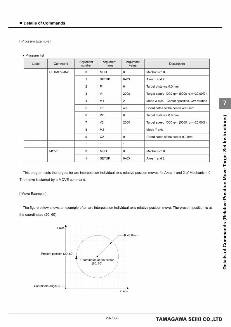
297/388
Details of Commands
7
Det
ails
of C
omm
ands
(Rel
ativ
e Po
sitio
n M
ove
Targ
et S
et In
stru
ctio
ns)
[ Program Example ]
• Program list
Label Command Argument number
Argument name
Argument value Description
0 MCH 0 Mechanism 0
1 SETUP 0x03 Axes 1 and 2
2 P1 0 Target distance 0.0 mm
3 V1 2000 Target speed 1000 rpm (5000 rpm×20.00%)
4 M1 2 Mode X axis Center specified, CW rotation
5 O1 400 Coordinates of the center 40.0 mm
6 P2 0 Target distance 0.0 mm
7 V2 2000 Target speed 1000 rpm (5000 rpm×20.00%)
8 M2 -1 Mode Y axis
SETMOVIJA2
9 O2 0 Coordinates of the center 0.0 mm
: : : : :
0 MCH 0 Mechanism 0 MOVE
1 SETUP 0x03 Axes 1 and 2
This program sets the targets for arc interpolation individual-axis relative position moves for Axes 1 and 2 of Mechanism 0.
The move is started by a MOVE command.
[ Move Example ]
The figure below shows an example of an arc interpolation individual-axis relative position move. The present position is at
the coordinates (20, 60).
Present position (20, 60)
Y axis
R 40.0mm
Coordinates of the center (60, 60)
X axis
Coordinate origin (0, 0)

298/388
Details of Commands
7
Det
ails
of C
omm
ands
(Rel
ativ
e Po
sitio
n M
ove
Targ
et S
et In
stru
ctio
ns)
■ SETMOVIJBL
[ Command Name ]
SETMOVIJBL [ Command Arguments ]
• Argument list
Argument number Argument list Description
0 MCH Specifies a mechanism number.
1 SETUP Specifies a setup axis number.
2 P1 Target distance (instruction unit)
3 S1 Target initial speed (unit of speed)
4 E1 Target end speed (unit of speed)
5 A1 Acceleration factor 1 (0.0001%)
6 B1
Axis 1 is set.
Acceleration factor 2 (0.0001%)
7 P2 Target distance (instruction unit)
8 S2 Target initial speed (unit of speed)
9 E2 Target end speed (unit of speed)
10 A2 Acceleration factor 1 (0.0001%)
11 B2
Axis 2 is set.
Acceleration factor 2 (0.0001%)
: : : :
22 P5 Target distance (instruction unit)
23 S5 Target initial speed (unit of speed)
24 E5 Target end speed (unit of speed)
25 A5 Acceleration factor 1 (0.0001%)
26 B5
Axis 5 is set.
Acceleration factor 2 (0.0001%)
[ Function Description ]
This command sets the targets for tertiary-speed individual-axis relative position moves.
If acceleration factors 1 and 2 are set to 100%, acceleration is made constant (linear move).
• Notes on the use of the SETMOVIJBL command
(A) To use a compound move command, set the correct values for the initial speed and the end speed.
(B) If a smooth move is not obtained for the initial-to-end speed transition between move commands, review the initial
speed value and the end speed value.

299/388
Details of Commands
7
Det
ails
of C
omm
ands
(Rel
ativ
e Po
sitio
n M
ove
Targ
et S
et In
stru
ctio
ns)
[ Program Example ]
• Program list
Label Command Argument number
Argument name
Argument value Description
0 MCH 0 Mechanism 0
1 SETUP 0x01 Axis 1
2 P1 1000 Target distance 100.0 mm
3 S1 0 Target initial speed 0 rpm
(5000 rpm×00.00%)
4 E1 2000 Target end speed 1000 rpm
(5000 rpm×20.00%)
5 A1 0 Acceleration factor 1 0.000%
SETMOVIJBL
6 B1 0 Acceleration factor 2 0.000%
: : : : :
0 MCH 0 Mechanism 0 MOVE
1 SETUP 0x01 Axis 1
This program sets the target for a tertiary-speed individual-axis relative position move for Axis 1 of Mechanism 0.
The move is started by a MOVE command.
[ Move Example 1 ]
The figure below shows examples of tertiary-speed individual-axis relative position moves. It shows a move with
acceleration factors 1 and 2 both set to 0%, another move with them both set to 50%, and another move with them both set to
100%.
MOVJBL command
Time
Speed
Target initial speed (0rpm)
Target end speed (1000rpm)
Acceleration factor 1=100.0% Acceleration factor 2=100.0%
Acceleration factor 1=50.0% Acceleration factor 2=50.0%
Acceleration factor 1=0.0% Acceleration factor 2=0.0%

300/388
Details of Commands
7
Det
ails
of C
omm
ands
(Rel
ativ
e Po
sitio
n M
ove
Targ
et S
et In
stru
ctio
ns)
[ Move Example 2 ]
The figure below shows examples of tertiary-speed individual-axis relative position moves. It shows a move with
acceleration factors 1 and 2 set individually to either 0% or 100% in the combinations indicated.

301/388
Details of Commands
7
Det
ails
of C
omm
ands
(Abs
olut
e Po
sitio
n M
ove
Inst
ruct
ions
)
Details of Absolute Position Move Instructions

302/388
Details of Commands
7
Det
ails
of C
omm
ands
(Abs
olut
e Po
sitio
n M
ove
Inst
ruct
ions
)
■ MOVAJ
[ Command Name ]
MOVAJ
[ Command Arguments ]
• Argument list
Argument number Argument list Description
0 MCH Specifies a mechanism number.
1 SETUP Specifies a setup axis number.
2 P1 Target position (instruction unit)
3 V1 Axis 1 is set.
Target speed (unit of speed)
4 P2 Target position (instruction unit)
5 V2 Axis 2 is set.
Target speed (unit of speed)
: : : :
28 P14 Target position (instruction unit)
29 V14 Axis 14 is set.
Target speed (unit of speed)
[ Function Description ]
This command performs individual-axis absolute position moves.
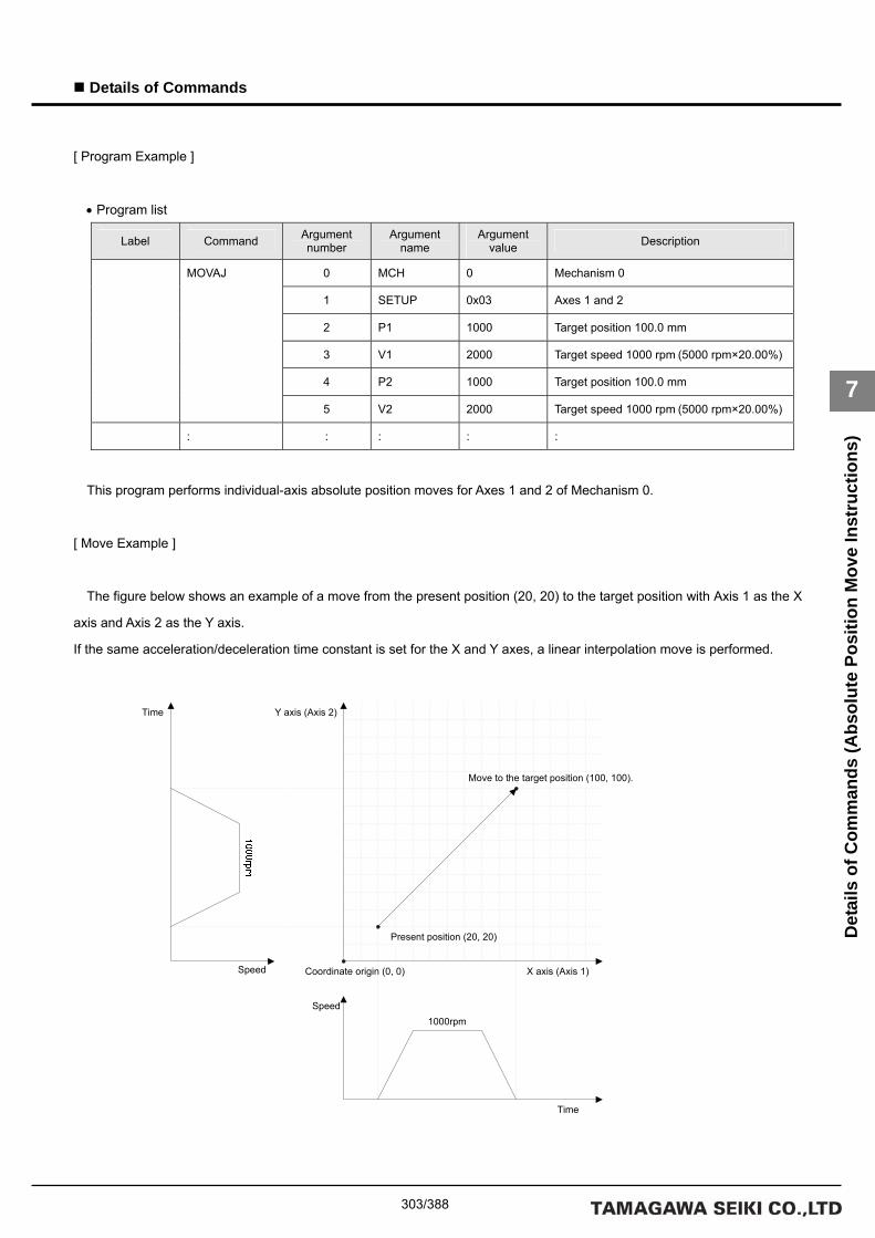
303/388
Details of Commands
7
Det
ails
of C
omm
ands
(Abs
olut
e Po
sitio
n M
ove
Inst
ruct
ions
)
[ Program Example ]
• Program list
Label Command Argument number
Argument name
Argument value Description
0 MCH 0 Mechanism 0
1 SETUP 0x03 Axes 1 and 2
2 P1 1000 Target position 100.0 mm
3 V1 2000 Target speed 1000 rpm (5000 rpm×20.00%)
4 P2 1000 Target position 100.0 mm
MOVAJ
5 V2 2000 Target speed 1000 rpm (5000 rpm×20.00%)
: : : : :
This program performs individual-axis absolute position moves for Axes 1 and 2 of Mechanism 0.
[ Move Example ]
The figure below shows an example of a move from the present position (20, 20) to the target position with Axis 1 as the X
axis and Axis 2 as the Y axis.
If the same acceleration/deceleration time constant is set for the X and Y axes, a linear interpolation move is performed.
Coordinate origin (0, 0)
Move to the target position (100, 100).
Y axis (Axis 2)
X axis (Axis 1)
Present position (20, 20)
1000rpm
Time
Speed
Time
Speed

304/388
Details of Commands
7
Det
ails
of C
omm
ands
(Abs
olut
e Po
sitio
n M
ove
Inst
ruct
ions
)
■ MOVAJT
[ Command Name ]
MOVAJT
[ Command Arguments ]
• Argument list
Argument number Argument list Description
0 MCH Specifies a mechanism number.
1 SETUP Specifies a setup axis number.
2 P1 Target position (instruction unit)
3 T1 Axis 1 is set.
Move time (usec)
4 P2 Target position (instruction unit)
5 T2 Axis 2 is set.
Move time (usec)
: : : :
28 P14 Target position (instruction unit)
29 T14 Axis 14 is set.
Move time (usec)
[ Function Description ]
This command performs time-specified individual-axis absolute position moves.

305/388
Details of Commands
7
Det
ails
of C
omm
ands
(Abs
olut
e Po
sitio
n M
ove
Inst
ruct
ions
)
[ Program Example ]
• Program list
Label Command Argument number
Argument name
Argument value Description
0 MCH 0 Mechanism 0
1 SETUP 0x01 Axis 1
2 P1 1000 Target position 100.0 mm
MOVAJT
3 T1 1000000 Move time 1.0 sec
: : : : :
This program performs a time-specified individual-axis absolute position move for Axis 1 of Mechanism 0.
[ Move Example ]
The figure below shows an example of a time-specified individual-axis absolute position move. Speeds are calculated
automatically by position and time.
The target time is the time period up to the completion of interpolation calculation. If an acceleration/deceleration time
constant is set, the move time is extended by the set time.

306/388
Details of Commands
7
Det
ails
of C
omm
ands
(Abs
olut
e Po
sitio
n M
ove
Inst
ruct
ions
)
■ MOVAJFS
[ Command Name ]
MOVAJFS
[ Command Arguments ]
• Argument list
Argument number Argument list Description
0 MCH Specifies a mechanism number.
1 SETUP Specifies a setup axis number.
2 P1 Target position (instruction unit)
3 S1 Target initial speed (unit of speed)
4 E1
Axis 1 is set.
Target end speed (unit of speed)
5 P2 Target position (instruction unit)
6 S2 Target initial speed (unit of speed)
7 E2
Axis 2 is set.
Target end speed (unit of speed)
: : : :
26 P9 Target position (instruction unit)
27 S9 Target initial speed (unit of speed)
28 E9
Axis 9 is set.
Target end speed (unit of speed)
[ Function Description ]
This command performs primary-speed individual-axis absolute position moves.
• Notes on the use of the MOVAJFS command
(A) To use a compound move command, set the correct values for the initial speed and the end speed.
(B) If a smooth move is not obtained for the initial-to-end speed transition between move commands, review the initial
speed value and the end speed value.

307/388
Details of Commands
7
Det
ails
of C
omm
ands
(Abs
olut
e Po
sitio
n M
ove
Inst
ruct
ions
)
[ Program Example ]
• Program list
Label Command Argument number
Argument name
Argument value Description
0 MCH 0 Mechanism 0
1 SETUP 0x01 Axis 1
2 P1 500 Target position 50.0 mm
3 S1 0 Target initial speed
0 rpm
(5000 rpm×00.00%)
MOVAJFS
4 E1 2000 Target end speed
1000 rpm
(5000 rpm×20.00%)
: : : : :
This program performs a primary-speed individual-axis absolute move for Axis 1 of Mechanism 0.
[ Move Example ]
The figure below shows an example of a primary-speed individual-axis absolute position move. Give the target initial speed
and the target end speed by arguments. This command is usually combined with multiple move commands to make a
compound move command.

308/388
Details of Commands
7
Det
ails
of C
omm
ands
(Abs
olut
e Po
sitio
n M
ove
Inst
ruct
ions
)
■ MOVAJCU
[ Command Name ]
MOVAJCU
[ Command Arguments ]
• Argument list
Argument number Argument list Description
0 MCH Specifies a mechanism number.
1 SETUP Specifies a setup axis number.
2 P1 Target position (instruction unit)
3 S1 Target initial speed (unit of speed)
4 E1 Target end speed (unit of speed)
5 T1
Axis 1 is set.
Move time (usec)
6 P2 Target position (instruction unit)
7 S2 Target initial speed (unit of speed)
8 E2 Target end speed (unit of speed)
9 T2
Axis 2 is set.
Move time (usec)
: : :
26 P7 Target position (instruction unit)
27 S7 Target initial speed (unit of speed)
28 E7 Target end speed (unit of speed)
29 T7
Axis 7 is set.
Move time (usec)
[ Function Description ]
This command performs secondary-speed individual-axis absolute position moves.
• Notes on the use of the MOVAJFS command
(A) To use a compound move command, set the correct values for the initial speed and the end speed.
(B) If a smooth move is not obtained for the initial-to-end speed transition between move commands, review the initial
speed value and the end speed value.

309/388
Details of Commands
7
Det
ails
of C
omm
ands
(Abs
olut
e Po
sitio
n M
ove
Inst
ruct
ions
)
[ Program Example ]
• Program list
Label Command Argument number
Argument name
Argument value Description
0 MCH 0 Mechanism 0
1 SETUP 0x01 Axis 1
2 P1 500 Target position 50.0 mm
3 S1 0 Target initial speed
0 rpm
(5000 rpm×00.00%)
4 E1 2000 Target end speed
1000 rpm
(5000 rpm×20.00%)
MOVAJCU
5 T1 500000 Move time 500 msec
: : : : :
This program performs a secondary-speed individual-axis absolute move for Axis 1 of Mechanism 0.
[ Move Example ]
The figure below shows an example of a secondary-speed individual-axis absolute position move. Give the move time,
target initial speed, and target end speed by arguments. This command is usually combined with multiple move commands to
make a compound move command.
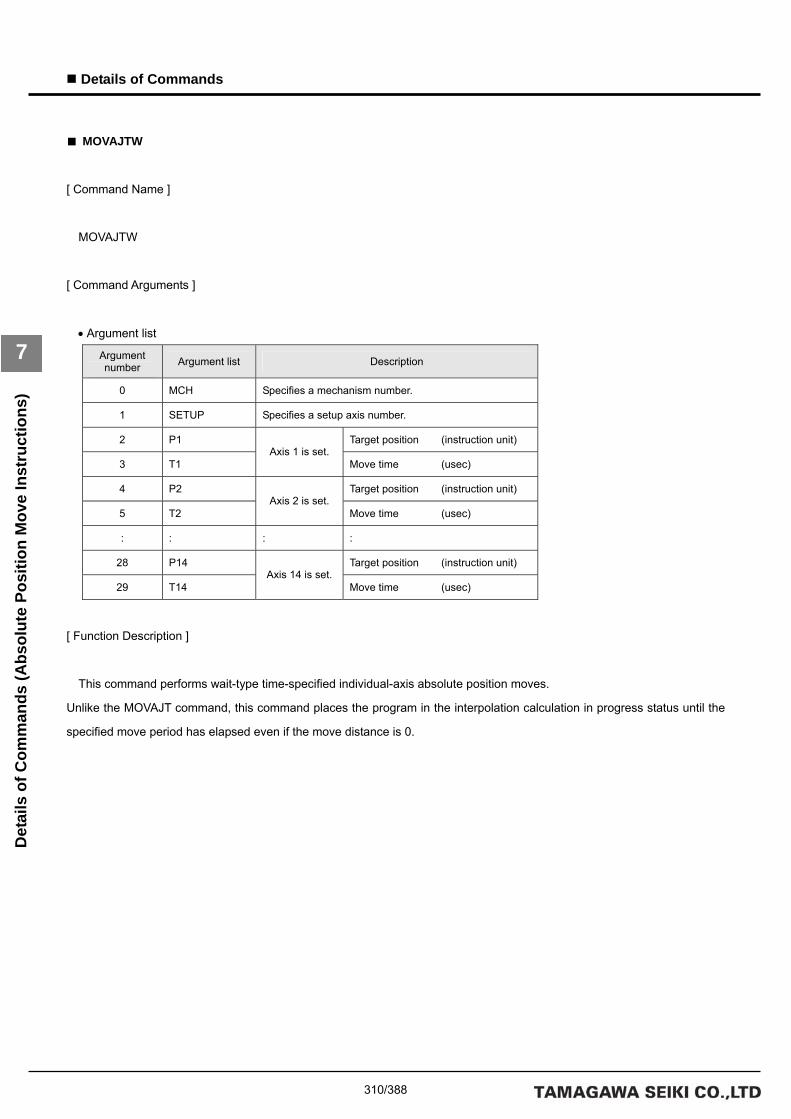
310/388
Details of Commands
7
Det
ails
of C
omm
ands
(Abs
olut
e Po
sitio
n M
ove
Inst
ruct
ions
)
■ MOVAJTW
[ Command Name ]
MOVAJTW
[ Command Arguments ]
• Argument list
Argument number Argument list Description
0 MCH Specifies a mechanism number.
1 SETUP Specifies a setup axis number.
2 P1 Target position (instruction unit)
3 T1 Axis 1 is set.
Move time (usec)
4 P2 Target position (instruction unit)
5 T2 Axis 2 is set.
Move time (usec)
: : : :
28 P14 Target position (instruction unit)
29 T14 Axis 14 is set.
Move time (usec)
[ Function Description ]
This command performs wait-type time-specified individual-axis absolute position moves.
Unlike the MOVAJT command, this command places the program in the interpolation calculation in progress status until the
specified move period has elapsed even if the move distance is 0.

311/388
Details of Commands
7
Det
ails
of C
omm
ands
(Abs
olut
e Po
sitio
n M
ove
Inst
ruct
ions
)
[ Program Example ]
• Program list
Label Command Argument number
Argument name
Argument value Description
0 MCH 0 Mechanism 0
1 SETUP 0x01 Axis 1
2 P1 1000 Target position 100.0 mm
MOVAJTW
3 V1 1000000 Move time 1.0 sec
: : : : :
This program performs a wait-type time-specified individual-axis absolute position move for Axis 1 of Mechanism 0.
[ Move Example ]
The figure below shows an example of a wait-type time-specified individual-axis absolute position move. Speeds are
calculated automatically by position and time.
The target time is the time period up to the completion of interpolation calculation. If an acceleration/deceleration time
constant is set, the move time is extended by the set time.

312/388
Details of Commands
7
Det
ails
of C
omm
ands
(Abs
olut
e Po
sitio
n M
ove
Inst
ruct
ions
)
■ MOVAJA1
[ Command Name ]
MOVAJA1
[ Command Arguments ]
• Argument list
Argument number Argument list Description
0 MCH Specifies a mechanism number.
1 SETUP Specifies a setup axis number.
2 P1 Target position (instruction unit)
3 V1 Target speed (unit of speed)
4 M1
Axis 1 is set.
Mode
5 P2 Target position (instruction unit)
6 V2 Target speed (unit of speed)
7 M2
Axis 2 is set.
Mode
: : : :
26 P9 Target position (instruction unit)
27 V9 Target speed (unit of speed)
28 M9
Axis 9 is set.
Mode
[ Function Description ]
This command performs right angle arc interpolation individual-axis absolute position moves (90-degree arc interpolation).
The following modes are available:
1 = X axis
0 = Synchronous axes (Z, Θ, etc.)
-1 = Y axis
• Notes on the use of the MOVAJA1 command
(A) To make the arc a perfect circle, specify the correct target position argument with respect to the present position.
The SVC determines the center coordinates of the arc based on the present position and the target position.

313/388
Details of Commands
7
Det
ails
of C
omm
ands
(Abs
olut
e Po
sitio
n M
ove
Inst
ruct
ions
)
[ Program Example ]
• Program list
Label Command Argument number
Argument name
Argument value Description
0 MCH 0 Mechanism 0
1 SETUP 0x03 Axes 1 and 2
2 P1 1000 Target position 100.0 mm
3 V1 2000 Target speed 1000 rpm (5000 rpm×20.00%)
4 M1 1 Mode X axis
5 P2 1000 Target position 100.0 mm
6 V2 2000 Target speed 1000 rpm (5000 rpm×20.00%)
MOVAJA1
7 M2 -1 Mode Y axis
: : : : :
This program performs right angle arc interpolation individual-axis absolute position moves for Axes 1 and 2 of Mechanism
0.
[ Move Example ]
The figure below shows an example of a right angle arc interpolation individual-axis absolute position move. The present
position is at the origin (0, 0) of the coordinate system.
100.0mm
Y axis
Center
X axis
Coordinate origin (0, 0)

314/388
Details of Commands
7
Det
ails
of C
omm
ands
(Abs
olut
e Po
sitio
n M
ove
Inst
ruct
ions
)
■ MOVAJA2
[ Command Name ]
MOVAJA2 [ Command Arguments ]
• Argument list
Argument number Argument list Description
0 MCH Specifies a mechanism number.
1 SETUP Specifies a setup axis number.
2 P1 Target position (instruction unit)
3 V1 Target speed (unit of speed)
4 M1 Mode
5 O1
Axis 1 is set.
Auxiliary data (center or angle)
6 P2 Target position (instruction unit)
7 V2 Target speed (unit of speed)
8 M2 Mode
9 O2
Axis 2 is set.
Auxiliary data (center or angle)
: : : :
26 P7 Target position (instruction unit)
27 V7 Target speed (unit of speed)
28 M7 Mode
29 O7
Axis 7 is set.
Auxiliary data (center or angle)
[ Function Description ]
This command performs arc-interpolation individual-axis absolute position moves. The following modes are available for
arc interpolation:
3 = X axis (center specified, CCW rotation)
2 = X axis (center specified, CW rotation)
1 = X axis (start point angle and end point angle specified)
0 = Synchronous axes (Z, Θ, etc.)
-1 = Y axis
• Notes on the use of the MOVAJA2 command
(A) To make the arc a perfect circle, specify the correct coordinates for the center.

315/388
Details of Commands
7
Det
ails
of C
omm
ands
(Abs
olut
e Po
sitio
n M
ove
Inst
ruct
ions
)
[ Program Example ]
• Program list
Label Command Argument number
Argument name
Argument value Description
0 MCH 0 Mechanism 0
1 SETUP 0x03 Axes 1 and 2
2 P1 200 Target position 20.0 mm
3 V1 2000 Target speed 1000 rpm (5000 rpm×20.00%)
4 M1 2 Mode X axis Center specified, CW rotation
5 O1 400 Coordinates of the center 40.0 mm
6 P2 600 Target position 60.0 mm
7 V2 2000 Target speed 1000 rpm (5000 rpm×20.00%)
8 M2 -1 Mode Y axis
MOVAJA2
9 O2 0 Coordinates of the center 0.0 mm
: : : : :
This program performs arc interpolation individual-axis absolute position moves for Axes 1 and 2 of Mechanism 0.
[ Move Example ]
The figure below shows an example of an arc interpolation individual-axis absolute position move. The present position is
at the coordinates (20, 60).
Present position (20, 60)
Y axis
R 40.0mm
Coordinates of the center (60, 60)
X axis
Coordinate origin (0, 0)

316/388
Details of Commands
7
Det
ails
of C
omm
ands
(Abs
olut
e Po
sitio
n M
ove
Inst
ruct
ions
)
■ MOVAJBL
[ Command Name ]
MOVAJBL [ Command Arguments ]
• Argument list
Argument number Argument list Description
0 MCH Specifies a mechanism number.
1 SETUP Specifies a setup axis number.
2 P1 Target position (instruction unit)
3 S1 Target initial speed (unit of speed)
4 E1 Target end speed (unit of speed)
5 A1 Acceleration factor 1 (0.0001%)
6 B1
Axis 1 is set.
Acceleration factor 2 (0.0001%)
7 P2 Target position (instruction unit)
8 S2 Target initial speed (unit of speed)
9 E2 Target end speed (unit of speed)
10 A2 Acceleration factor 1 (0.0001%)
11 B2
Axis 2 is set.
Acceleration factor 2 (0.0001%)
: : : :
22 P5 Target position (instruction unit)
23 S5 Target initial speed (unit of speed)
24 E5 Target end speed (unit of speed)
25 A5 Acceleration factor 1 (0.0001%)
26 B5
Axis 5 is set.
Acceleration factor 2 (0.0001%)
[ Function Description ]
This command performs tertiary-speed individual-axis absolute position moves.
If acceleration factors 1 and 2 are set to 100%, acceleration is made constant (linear move).
• Notes on the use of the MOVAJBL command
(A) To use a compound move command, set the correct values for the initial speed and the end speed.
(B) If a smooth move is not obtained for the initial-to-end speed transition between move commands, review the initial
speed value and the end speed value.

317/388
Details of Commands
7
Det
ails
of C
omm
ands
(Abs
olut
e Po
sitio
n M
ove
Inst
ruct
ions
)
[ Program Example ]
• Program list
Label Command Argument number
Argument name
Argument value Description
0 MCH 0 Mechanism 0
1 SETUP 0x01 Axis 1
2 P1 1000 Target position 100.0 mm
3 S1 0 Target initial speed
0 rpm
(5000 rpm×00.00%)
4 E1 2000 Target end speed
1000 rpm
(5000 rpm×20.00%)
5 A1 0 Acceleration factor 1 0.000%
MOVAJBL
6 B1 0 Acceleration factor 2 0.000%
: : : : :
This program performs a tertiary-speed individual-axis absolute position move for Axis 1 of Mechanism 0.
[ Move Example 1 ]
The figure below shows examples of tertiary-speed individual-axis absolute position moves. It shows a move with
acceleration factors 1 and 2 both set to 0%, another move with them both set to 50%, and another move with them both set to
100%.
MOVJBL command
Time
Speed
Target initial speed (0rpm)
Target end speed (1000rpm)
Acceleration factor 1=100.0% Acceleration factor 2=100.0%
Acceleration factor 1=50.0% Acceleration factor 2=50.0%
Acceleration factor 1=0.0% Acceleration factor 2=0.0%

318/388
Details of Commands
7
Det
ails
of C
omm
ands
(Abs
olut
e Po
sitio
n M
ove
Inst
ruct
ions
)
[ Move Example 2 ]
The figure below shows examples of tertiary-speed individual-axis absolute position moves. It shows a move with
acceleration factors 1 and 2 set individually to either 0% or 100% in the combinations indicated.

319/388
Details of Commands
7
Det
ails
of C
omm
ands
(Rel
ativ
e Po
sitio
n M
ove
Inst
ruct
ions
)
Details of Relative Position Move Instructions

320/388
Details of Commands
7
Det
ails
of C
omm
ands
(Rel
ativ
e Po
sitio
n M
ove
Inst
ruct
ions
)
■ MOVIJ
[ Command Name ]
MOVIJ
[ Command Arguments ]
• Argument list
Argument number Argument list Description
0 MCH Specifies a mechanism number.
1 SETUP Specifies a setup axis number.
2 P1 Target distance (instruction unit)
3 V1 Axis 1 is set.
Target speed (unit of speed)
4 P2 Target distance (instruction unit)
5 V2 Axis 2 is set.
Target speed (unit of speed)
: : : :
28 P14 Target distance (instruction unit)
29 V14 Axis 14 is set.
Target speed (unit of speed)
[ Function Description ]
This command performs individual-axis relative position moves.

321/388
Details of Commands
7
Det
ails
of C
omm
ands
(Rel
ativ
e Po
sitio
n M
ove
Inst
ruct
ions
)
[ Program Example ]
• Program list
Label Command Argument number
Argument name
Argument value Description
0 MCH 0 Mechanism 0
1 SETUP 0x03 Axes 1 and 2
2 P1 800 Target distance 80.0 mm
3 V1 2000 Target speed 1000 rpm
(5000 rpm×20.00%)
4 P2 800 Target distance 80.0 mm
MOVIJ
5 V2 2000 Target speed 1000 rpm
(5000 rpm×20.00%)
: : : : :
This program performs individual-axis absolute position moves for Axes 1 and 2 of Mechanism 0.
[ Move Example ]
The figure below shows an example of a move by the target distance from the present position (20, 20) with Axis 1 as the X
axis and Axis 2 as the Y axis.
If the same acceleration/deceleration time constant is set for the X and Y axes, a linear interpolation move is performed.
Coordinate origin (0, 0)
Move to the target position (100, 100).
Y axis (Axis 2)
X axis (Axis 1)
Present position (20, 20)
1000rpm
Time
Speed
Time
Speed

322/388
Details of Commands
7
Det
ails
of C
omm
ands
(Rel
ativ
e Po
sitio
n M
ove
Inst
ruct
ions
)
■ MOVIJT
[ Command Name ]
MOVIJT
[ Command Arguments ]
• Argument list
Argument number Argument list Description
0 MCH Specifies a mechanism number.
1 SETUP Specifies a setup axis number.
2 P1 Target distance (instruction unit)
3 T1 Axis 1 is set.
Move time (usec)
4 P2 Target distance (instruction unit)
5 T2 Axis 2 is set.
Move time (usec)
: : : :
28 P14 Target distance (instruction unit)
29 T14 Axis 14 is set.
Move time (usec)
[ Function Description ]
This command performs time-specified individual-axis relative position moves.

323/388
Details of Commands
7
Det
ails
of C
omm
ands
(Rel
ativ
e Po
sitio
n M
ove
Inst
ruct
ions
)
[ Program Example ]
• Program list
Label Command Argument number
Argument name
Argument value Description
0 MCH 0 Mechanism 0
1 SETUP 0x01 Axis 1
2 P1 1000 Target distance 100.0 mm
MOVIJT
3 T1 1000000 Move time 1.0 sec
: : : : :
This program performs a time-specified individual-axis relative position move for Axis 1 of Mechanism 0.
[ Move Example ]
The figure below shows an example of a time-specified individual-axis relative position move. Speeds are calculated
automatically by position and time.
The target time is the time period up to the completion of interpolation calculation. If an acceleration/deceleration time
constant is set, the move time is extended by the set time.

324/388
Details of Commands
7
Det
ails
of C
omm
ands
(Rel
ativ
e Po
sitio
n M
ove
Inst
ruct
ions
)
■ MOVIJFS
[ Command Name ]
MOVIJFS
[ Command Arguments ]
• Argument list
Argument number Argument list Description
0 MCH Specifies a mechanism number.
1 SETUP Specifies a setup axis number.
2 P1 Target distance (instruction unit)
3 S1 Target initial speed (unit of speed)
4 E1
Axis 1 is set.
Target end speed (unit of speed)
5 P2 Target distance (instruction unit)
6 S2 Target initial speed (unit of speed)
7 E2
Axis 2 is set.
Target end speed (unit of speed)
: : : :
26 P9 Target distance (instruction unit)
27 S9 Target initial speed (unit of speed)
28 E9
Axis 9 is set.
Target end speed (unit of speed)
[ Function Description ]
This command performs primary-speed individual-axis relative position moves.
• Notes on the use of the MOVIJFS command
(A) To use a compound move command, set the correct values for the initial speed and the end speed.
(B) If a smooth move is not obtained for the initial-to-end speed transition between move commands, review the initial
speed value and the end speed value.

325/388
Details of Commands
7
Det
ails
of C
omm
ands
(Rel
ativ
e Po
sitio
n M
ove
Inst
ruct
ions
)
[ Program Example ]
• Program list
Label Command Argument number
Argument name
Argument value Description
0 MCH 0 Mechanism 0
1 SETUP 0x01 Axis 1
2 P1 500 Target distance 50.0 mm
3 S1 0 Target initial speed 0 rpm
(5000 rpm×00.00%)
MOVIJFS
4 E1 2000 Target end speed 1000 rpm
(5000 rpm×20.00%)
: : : : :
This program performs a primary-speed individual-axis relative position move for Axis 1 of Mechanism 0.
[ Move Example ]
The figure below shows an example of a primary-speed individual-axis relative position move. Give the target initial speed
and the target end speed by arguments. This command is usually combined with multiple move commands to make a
compound move command.

326/388
Details of Commands
7
Det
ails
of C
omm
ands
(Rel
ativ
e Po
sitio
n M
ove
Inst
ruct
ions
)
■ MOVIJCU
[ Command Name ]
MOVIJCU
[ Command Arguments ]
• Argument list
Argument number Argument list Description
0 MCH Specifies a mechanism number.
1 SETUP Specifies a setup axis number.
2 P1 Target distance (instruction unit)
3 S1 Target initial speed (unit of speed)
4 E1 Target end speed (unit of speed)
5 T1
Axis 1 is set.
Move time (usec)
6 P2 Target distance (instruction unit)
7 S2 Target initial speed (unit of speed)
8 E2 Target end speed (unit of speed)
9 T2
Axis 2 is set.
Move time (usec)
: : :
26 P7 Target distance (instruction unit)
27 S7 Target initial speed (unit of speed)
28 E7 Target end speed (unit of speed)
29 T7
Axis 7 is set.
Move time (usec)
[ Function Description ]
This command performs secondary-speed individual-axis relative position moves. • Notes on the use of the MOVIJCU command
(A) To use a compound move command, set the correct values for the initial speed and the end speed.
(B) If a smooth move is not obtained for the initial-to-end speed transition between move commands, review the initial
speed value and the end speed value.
(C) When using the JCU command, check the speed data by means of the monitor function after the program is created.
If improper time values are specified, the speed will overshoot and then undershoot (reverse rotation followed by
forward rotation).
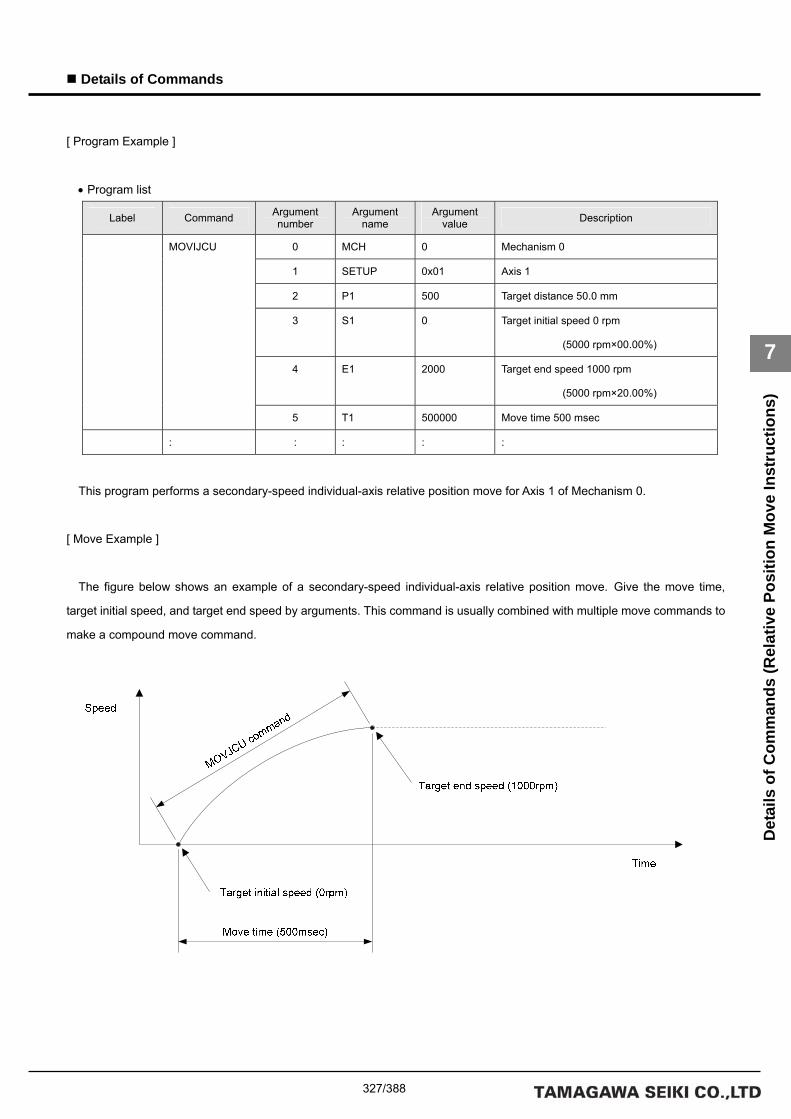
327/388
Details of Commands
7
Det
ails
of C
omm
ands
(Rel
ativ
e Po
sitio
n M
ove
Inst
ruct
ions
)
[ Program Example ]
• Program list
Label Command Argument number
Argument name
Argument value Description
0 MCH 0 Mechanism 0
1 SETUP 0x01 Axis 1
2 P1 500 Target distance 50.0 mm
3 S1 0 Target initial speed 0 rpm
(5000 rpm×00.00%)
4 E1 2000 Target end speed 1000 rpm
(5000 rpm×20.00%)
MOVIJCU
5 T1 500000 Move time 500 msec
: : : : :
This program performs a secondary-speed individual-axis relative position move for Axis 1 of Mechanism 0.
[ Move Example ]
The figure below shows an example of a secondary-speed individual-axis relative position move. Give the move time,
target initial speed, and target end speed by arguments. This command is usually combined with multiple move commands to
make a compound move command.

328/388
Details of Commands
7
Det
ails
of C
omm
ands
(Rel
ativ
e Po
sitio
n M
ove
Inst
ruct
ions
)
■ MOVIJTW
[ Command Name ]
MOVIJTW
[ Command Arguments ]
• Argument list
Argument number Argument list Description
0 MCH Specifies a mechanism number.
1 SETUP Specifies a setup axis number.
2 P1 Target distance (instruction unit)
3 T1 Axis 1 is set.
Move time (usec)
4 P2 Target distance (instruction unit)
5 T2 Axis 2 is set.
Move time (usec)
: : : :
28 P14 Target distance (instruction unit)
29 T14 Axis 14 is set.
Move time (usec)
[ Function Description ]
This command performs wait-type time-specified individual-axis relative position moves.
Unlike the MOVIJT command, this command places the program in the interpolation calculation in progress status until the
specified move period has elapsed even if the move distance is 0.
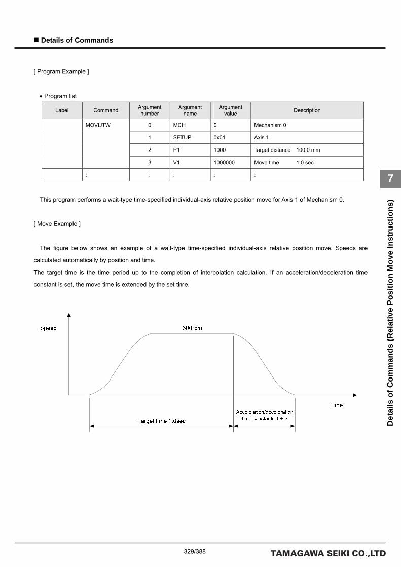
329/388
Details of Commands
7
Det
ails
of C
omm
ands
(Rel
ativ
e Po
sitio
n M
ove
Inst
ruct
ions
)
[ Program Example ]
• Program list
Label Command Argument number
Argument name
Argument value Description
0 MCH 0 Mechanism 0
1 SETUP 0x01 Axis 1
2 P1 1000 Target distance 100.0 mm
MOVIJTW
3 V1 1000000 Move time 1.0 sec
: : : : :
This program performs a wait-type time-specified individual-axis relative position move for Axis 1 of Mechanism 0.
[ Move Example ]
The figure below shows an example of a wait-type time-specified individual-axis relative position move. Speeds are
calculated automatically by position and time.
The target time is the time period up to the completion of interpolation calculation. If an acceleration/deceleration time
constant is set, the move time is extended by the set time.

330/388
Details of Commands
7
Det
ails
of C
omm
ands
(Rel
ativ
e Po
sitio
n M
ove
Inst
ruct
ions
)
■ MOVIJA1
[ Command Name ]
MOVIJA1
[ Command Arguments ]
• Argument list
Argument number Argument list Description
0 MCH Specifies a mechanism number.
1 SETUP Specifies a setup axis number.
2 P1 Target distance (instruction unit)
3 V1 Target speed (unit of speed)
4 M1
Axis 1 is set.
Mode
5 P2 Target distance (instruction unit)
6 V2 Target speed (unit of speed)
7 M2
Axis 2 is set.
Mode
: : : :
26 P9 Target distance (instruction unit)
27 V9 Target speed (unit of speed)
28 M9
Axis 9 is set.
Mode
[ Function Description ]
This command performs right angle arc interpolation individual-axis relative position moves (90-degree arc interpolation).
The following modes are available:
1 = X axis
0 = Synchronous axes (Z, Θ, etc.)
-1 = Y axis
• Notes on the use of the MOVIJA1 command
(A) To make the arc a perfect circle, specify the correct target position argument with respect to the present position.
The SVC determines the center coordinates of the arc based on the present position and the target position.

331/388
Details of Commands
7
Det
ails
of C
omm
ands
(Rel
ativ
e Po
sitio
n M
ove
Inst
ruct
ions
)
[ Program Example ]
• Program list
Label Command Argument number
Argument name
Argument value Description
0 MCH 0 Mechanism 0
1 SETUP 0x03 Axes 1 and 2
2 P1 1000 Target distance 100.0 mm
3 V1 2000 Target speed 1000 rpm
(5000 rpm×20.00%)
4 M1 1 Mode X axis
5 P2 1000 Target distance 100.0 mm
6 V2 2000 Target speed 1000 rpm
(5000 rpm×20.00%)
MOVIJA1
7 M2 -1 Mode Y axis
: : : : :
This program performs right angle arc interpolation individual-axis relative position moves for Axes 1 and 2 of Mechanism
0.
[ Move Example ]
The figure below shows an example of a right angle arc interpolation individual-axis relative position move. The present
position is at the origin (0, 0) of the coordinate system.
100.0mm
Y axis
Center
X axis
Coordinate origin (0, 0)

332/388
Details of Commands
7
Det
ails
of C
omm
ands
(Rel
ativ
e Po
sitio
n M
ove
Inst
ruct
ions
)
■ MOVIJA2
[ Command Name ]
MOVIJA2
[ Command Arguments ]
• Argument list
Argument number Argument list Description
0 MCH Specifies a mechanism number.
1 SETUP Specifies a setup axis number.
2 P1 Target distance (instruction unit)
3 V1 Target speed (unit of speed)
4 M1 Mode
5 O1
Axis 1 is set.
Auxiliary data (center or angle)
6 P2 Target distance (instruction unit)
7 V2 Target speed (unit of speed)
8 M2 Mode
9 O2
Axis 2 is set.
Auxiliary data (center or angle)
: : : :
26 P7 Target distance (instruction unit)
27 V7 Target speed (unit of speed)
28 M7 Mode
29 O7
Axis 7 is set.
Auxiliary data (center or angle)
[ Function Description ]
This command performs arc-interpolation individual-axis relative position moves. The following modes are available for arc
interpolation:
3 = X axis (center specified, CCW rotation)
2 = X axis (center specified, CW rotation)
1 = X axis (start point angle and end point angle specified)
0 = Synchronous axes (Z, Θ, etc.)
-1 = Y axis
• Notes on the use of the MOVIJA2 command
(A) To make the arc a perfect circle, specify the correct coordinates for the center.

333/388
Details of Commands
7
Det
ails
of C
omm
ands
(Rel
ativ
e Po
sitio
n M
ove
Inst
ruct
ions
)
[ Program Example ]
• Program list
Label Command Argument number
Argument name
Argument value Description
0 MCH 0 Mechanism 0
1 SETUP 0x03 Axes 1 and 2
2 P1 0 Target distance 0.0 mm
3 V1 2000 Target speed 1000 rpm
(5000 rpm×20.00%)
4 M1 2 Mode X axis Center specified, CW rotation
5 O1 400 Coordinates of the center 40.0 mm
6 P2 0 Target distance 0.0 mm
7 V2 2000 Target speed 1000 rpm
(5000 rpm×20.00%)
8 M2 -1 Mode Y axis
MOVIJA2
9 O2 0 Coordinates of the center 0.0 mm
: : : : :
This program performs arc interpolation individual-axis relative position moves for Axes 1 and 2 of Mechanism 0.
[ Move Example ]
The figure below shows an example of an arc interpolation individual-axis relative position move. The present position is at
the coordinates (20, 60).
Present position (20, 60)
Y axis
R 40.0mm
Coordinates of the center (60, 60)
X axis
Coordinate origin (0, 0)

334/388
Details of Commands
7
Det
ails
of C
omm
ands
(Rel
ativ
e Po
sitio
n M
ove
Inst
ruct
ions
)
■ MOVIJBL
[ Command Name ]
MOVIJBL [ Command Arguments ]
• Argument list
Argument number Argument list Description
0 MCH Specifies a mechanism number.
1 SETUP Specifies a setup axis number.
2 P1 Target distance (instruction unit)
3 S1 Target initial speed (unit of speed)
4 E1 Target end speed (unit of speed)
5 A1 Acceleration factor 1 (0.0001%)
6 B1
Axis 1 is set.
Acceleration factor 2 (0.0001%)
7 P2 Target distance (instruction unit)
8 S2 Target initial speed (unit of speed)
9 E2 Target end speed (unit of speed)
10 A2 Acceleration factor 1 (0.0001%)
11 B2
Axis 2 is set.
Acceleration factor 2 (0.0001%)
: : : :
22 P5 Target distance (instruction unit)
23 S5 Target initial speed (unit of speed)
24 E5 Target end speed (unit of speed)
25 A5 Acceleration factor 1 (0.0001%)
26 B5
Axis 5 is set.
Acceleration factor 2 (0.0001%)
[ Function Description ]
This command performs tertiary-speed individual-axis relative position moves.
If acceleration factors 1 and 2 are set to 100%, acceleration is made constant (linear move).
• Notes on the use of the MOVIJBL command
(A) To use a compound move command, set the correct values for the initial speed and the end speed.
(B) If a smooth move is not obtained for the initial-to-end speed transition between move commands, review the initial
speed value and the end speed value.

335/388
Details of Commands
7
Det
ails
of C
omm
ands
(Rel
ativ
e Po
sitio
n M
ove
Inst
ruct
ions
)
[ Program Example ]
• Program list
Label Command Argument number
Argument name
Argument value Description
0 MCH 0 Mechanism 0
1 SETUP 0x01 Axis 1
2 P1 1000 Target distance 100.0 mm
3 S1 0 Target initial speed 0 rpm
(5000 rpm×00.00%)
4 E1 2000 Target end speed 1000 rpm
(5000 rpm×20.00%)
5 A1 0 Acceleration factor 1 0.000%
MOVIJBL
6 B1 0 Acceleration factor 2 0.000%
: : : : :
This program performs a tertiary-speed individual-axis relative position move for Axis 1 of Mechanism 0.
[ Move Example 1 ]
The figure below shows examples of tertiary-speed individual-axis relative position moves. It shows a move with
acceleration factors 1 and 2 both set to 0%, another move with them both set to 50%, and another move with them both set to
100%.
MOVJBL command
Time
Speed
Target initial speed (0rpm)
Target end speed (1000rpm)
Acceleration factor 1=100.0% Acceleration factor 2=100.0%
Acceleration factor 1=50.0% Acceleration factor 2=50.0%
Acceleration factor 1=0.0% Acceleration factor 2=0.0%
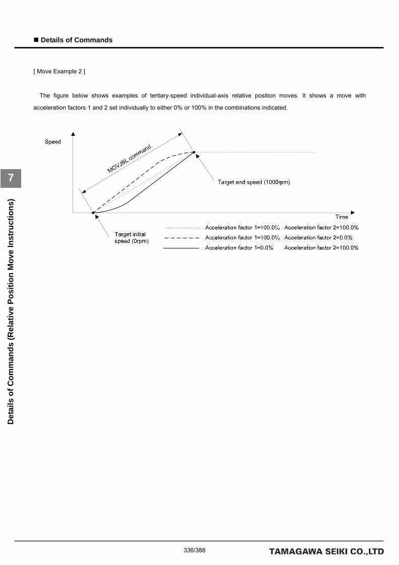
336/388
Details of Commands
7
Det
ails
of C
omm
ands
(Rel
ativ
e Po
sitio
n M
ove
Inst
ruct
ions
)
[ Move Example 2 ]
The figure below shows examples of tertiary-speed individual-axis relative position moves. It shows a move with
acceleration factors 1 and 2 set individually to either 0% or 100% in the combinations indicated.

337/388
Details of Commands
7
Det
ails
of C
omm
ands
(Mov
e C
ontr
ol In
stru
ctio
ns)
Details of Move Control Instructions

338/388
Details of Commands
7
Det
ails
of C
omm
ands
(Mov
e C
ontr
ol In
stru
ctio
ns)
■ MOVE
[ Command Name ]
MOVE
[ Command Arguments ]
• Argument list
Argument number Argument list Description
0 MCH Specifies a mechanism number.
1 SETUP Specifies a setup axis number.
[ Function Description ]
This command actually starts moving the axes according to the set target commands.
The bits associated with the axes to be moved this time are set in the setup axis number.
The SVC ignores set data for axes not set in the setup axis number.
Note that the SVC clears all set data if 0x00000000 is specified as the setup axis number.
[ Program Example ]
• Program list
Label Command Argument number
Argument name
Argument value Description
0 MCH 0 Mechanism 0 MOVE
1 SETUP 0x07 Axes 1, 2, and 3
This program start moving Axes 1, 2, and 3 of Mechanism 0.

339/388
Details of Commands
7
Det
ails
of C
omm
ands
(Mov
e C
ontr
ol In
stru
ctio
ns)
■ STOP
[ Command Name ]
STOP
[ Command Arguments ]
• Argument list
Argument number Argument list Description
0 MCH Specifies a mechanism number.
1 LVL Specifies a stop request level.
(0: No stop processing; 1: Deceleration stop; 2: Immediate stop)
2 AFT Specifies post-stop processing.
(0: None; 1: Servo OFF)
[ Function Description ]
This command stops the move for the mechanism.
Options for stop processing and post-stop processing can be set.
[ Program Example ]
• Program list
Label Command Argument number
Argument name
Argument value Description
0 MCH 0 Mechanism 0
1 LVL 1 Stop processing: Deceleration stop
STOP
2 AFT 1 Post-stop processing: Servo OFF
This program executes servo OFF for all axes belonging to the mechanism after completion of deceleration stop.
• Notes on the use of the STOP command
(A) If “0: No stop processing” is specified for stop request level, the SVC does nothing. The specified options are also
disabled.
(B) The “0: No stop processing” setting for stop request level is disabled for axes moving in speed control mode, electric
current control mode, or homing mode (HOMESV or HOMEBUMP). Specify “Deceleration stop” or higher for the stop
request level.
The speed of deceleration during deceleration stop depends on the setting within the driver.

340/388
Details of Commands
7
Det
ails
of C
omm
ands
(Mov
e C
ontr
ol In
stru
ctio
ns)
■ SETOVR
[ Command Name ]
SETOVR
[ Command Arguments ]
• Argument list
Argument number Argument list Description
0 MCH Specifies a mechanism number.
1 TYPE Data type (0: 0.01%; 1: Numerator & denominator)
2 OVR Override number
3 VAL1 Override value or numerator
4 VAL2 Invalid or denominator
[ Function Description ]
This command sets speed override data items for the mechanism.
Four speed override data items are provided for each mechanism. The product of all speed override data items is used last.
[ Program Example ]
• Program list
Label Command Argument number
Argument name
Argument value Description
0 MCH 0 Mechanism 0
1 TYPE 1 Data type Numerator & denominator
2 OVR 0 Override number 0
3 VAL1 50 Numerator data 50
SETOVR
4 VAL2 100 Denominator data 100
This program sets 50 to the numerator data and 100 to the denominator data for Override 0 of Mechanism 0.

341/388
Details of Commands
7
Det
ails
of C
omm
ands
(Mov
e C
ontr
ol In
stru
ctio
ns)
■ GETOVR
[ Command Name ]
GETOVR
[ Command Arguments ]
• Argument list
Argument number Argument list Description
0 MCH Specifies a mechanism number.
1 TYPE Data type (0: 0.01%; 1: Numerator & denominator)
2 OVR Override number
3 VAR1 Override value or numerator
4 VAR2 Invalid or denominator
[ Function Description ]
This command obtains speed override data items in variables VAR1 and VAR2.
Four speed override data items are provided for each mechanism. The product of all speed override data items is used last.
[ Program Example ]
• Program list
Label Command Argument number
Argument name
Argument value Description
0 MCH 0 Mechanism 0
1 TYPE 1 Data type Numerator & denominator
2 OVR 0 Override number 0
3 VAR1 TEMP1 Variable TEMP1
GETOVR
4 VAR2 TEMP2 Variable TEMP2
This program stores the numerator data in variable TEMP1 and the denominator data in variable TEMP2 for Override 0 of
Mechanism 0.

342/388
Details of Commands
7
Det
ails
of C
omm
ands
(Mov
e C
ontr
ol In
stru
ctio
ns)
■ SETWAIT
[ Command Name ]
SETWAIT
[ Command Arguments ]
• Argument list
Argument number Argument list Description
0 MCH Specifies a mechanism number.
1 LVL Wait level
(0: No wait; 1: Wait for interpolation calculation; 2: Wait for acceleration/deceleration; 3: Wait for
in-position)
2 INPOS 0: Follow the SVD.
3 DELAY Additional delay time (unit: msec). No delay if 0 is specified.
[ Function Description ]
This command sets the move completion wait mode for the mechanism.
For the “Additional delay time (DELAY)” argument, specify the additional delay time that is to elapse after the condition has
been satisfied. (No delay is performed if 0 is specified.)
If 0 is specified for both the “Wait level (LVL)” and “Additional delay time (DELAY) arguments, ordinary no-wait mode is
assumed.
The initial state is no-wait mode.
[ Program Example ]
• Program list
Label Command Argument number
Argument name
Argument value Description
0 MCH 0 Mechanism 0
1 LVL 3 Wait level: Wait for in-position
2 INPOS 0 Follow in-position of the SVD.
SETWAIT
3 DELAY 100 Additional delay time 100 msec
This program sets “Wait for in-position” to the “Wait level” argument and 100 msec to the “Additional delay time” argument
for Mechanism 0.

343/388
Details of Commands
7
Det
ails
of C
omm
ands
(Mov
e C
ontr
ol In
stru
ctio
ns)
■ GETWAIT
[ Command Name ]
GETWAIT
[ Command Arguments ]
• Argument list
Argument number Argument list Description
0 MCH Specifies a mechanism number.
1 TYPE Specifies a data type.
2 VAR Specifies a variable number.
[ Function Description ]
This command obtains the move completion wait mode of the mechanism.
Data type 0: Wait level
1: In-position width
2: Additional delay item
[ Program Example ]
• Program list
Label Command Argument number
Argument name
Argument value Description
0 MCH 0 Mechanism 0
1 TYPE 0 Data type: Wait level
GETWAIT
2 VAR TEMP Variable TEMP
This program stores the wait level for Mechanism 0 to variable TEMP.
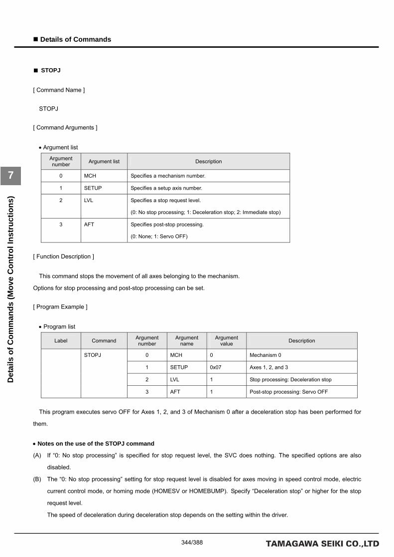
344/388
Details of Commands
7
Det
ails
of C
omm
ands
(Mov
e C
ontr
ol In
stru
ctio
ns)
■ STOPJ
[ Command Name ]
STOPJ [ Command Arguments ]
• Argument list
Argument number Argument list Description
0 MCH Specifies a mechanism number.
1 SETUP Specifies a setup axis number.
2 LVL Specifies a stop request level.
(0: No stop processing; 1: Deceleration stop; 2: Immediate stop)
3 AFT Specifies post-stop processing.
(0: None; 1: Servo OFF)
[ Function Description ]
This command stops the movement of all axes belonging to the mechanism.
Options for stop processing and post-stop processing can be set. [ Program Example ]
• Program list
Label Command Argument number
Argument name
Argument value Description
0 MCH 0 Mechanism 0
1 SETUP 0x07 Axes 1, 2, and 3
2 LVL 1 Stop processing: Deceleration stop
STOPJ
3 AFT 1 Post-stop processing: Servo OFF
This program executes servo OFF for Axes 1, 2, and 3 of Mechanism 0 after a deceleration stop has been performed for
them.
• Notes on the use of the STOPJ command
(A) If “0: No stop processing” is specified for stop request level, the SVC does nothing. The specified options are also
disabled.
(B) The “0: No stop processing” setting for stop request level is disabled for axes moving in speed control mode, electric
current control mode, or homing mode (HOMESV or HOMEBUMP). Specify “Deceleration stop” or higher for the stop
request level.
The speed of deceleration during deceleration stop depends on the setting within the driver.

345/388
Appendix
List
of P
aram
eter
s (S
VCC
Ser
ies)
Appendix
8. Appendix
List of Parameters
(A) SVCC Series
System-Related Parameters
Class number Group number ID number Description W S
0 Memory switch
1 Basic processing period (unit: usec)
2 Upper limit for host command reception interval (unit:
msec)
Not checked if 0 is specified.
3 Time for determining whether or not the host command is
executable (unit: msec)
Not checked if 0 is specified.
4 Variable number to be written in the event of a host
command error
5 Task number to be written in the event of a host command
error
6 Reserved
7 Reserved
8 Reserved
0
Basic configuration
9 Reserved
0 Product model (TA number)
1 Product model (N number)
2 Product model (E number)
3 Serial number (first 4 characters)
4 Serial number (second 4 characters)
5 Reserved
6 Reserved
7 Reserved
8 Reserved
0x0010
System-related
parameters
1
Product information
9 Reserved

346/388
Appendix
Appendix
List
of P
aram
eter
s (S
VCC
Ser
ies)
Class number Group number ID number Description W S
0 Default of the SV-NET CH1 baud rate: 4 (1 Mbps)
1 Default of the SV-NET CH2 baud rate: 1 (250 Kbps)
2 Reserved
3 Reserved
4 Reserved
5 Reserved
6 Reserved
7 Reserved
8 Reserved
2
SV-NET
9 Reserved
0 Default of the RS232C baud rate: 2 (38400 bps)
1 Default of the number of data elements: 0 (8 bits)
2 Default of the stop bit polarity: 0 (1 bit)
3 Default of the parity: 0 (none)
4 Reserved
5 Operation in the event of an alarm
6 Reserved
7 Communication mode
8 Communication timeout
3
RS232C basic
configuration
9 Response wait
0 Automatic send/receive mode
1 Initial address of the device in automatic send/receive
mode (Read)
2 Initial address of the device in automatic send/receive
mode (Write)
3 Number of data elements per session in automatic
send/receive mode
4 Number of times read and write are repeated in automatic
send/receive mode
5 Initial address of the network variable (Read)
6 Initial address of the network variable (Write)
7 Communication interval
8 Device type (ASCII code at the first character position)
0x0010
System-related
parameters
4
RS232C automatic
send/receive mode
9 Device type (ASCII code at the second character position)

347/388
Appendix
List
of P
aram
eter
s (S
VCC
Ser
ies)
Appendix
Class number Group number ID number Description W S
0 Reserved
1 Reserved
2 Reserved
3 Reserved
4 Reserved
5 Reserved
6 Reserved
7 Reserved
8 Reserved
7
Reserved
9 Reserved
0 Reserved
1 Reserved
2 Reserved
3 Reserved
4 Reserved
5 Reserved
6 Reserved
7 Reserved
8 Reserved
5
Reserved
9 Reserved
0 Reserved
1 Reserved
2 Reserved
3 Reserved
4 Reserved
5 Reserved
6 Reserved
7 Reserved
8 Reserved
0x0010
System-related
parameters
6
Reserved
9 Reserved

348/388
Appendix
Appendix
List
of P
aram
eter
s (S
VCC
Ser
ies)
Class number Group number ID number Description W S
0 Alarm history 1
1 Alarm history 2
2 Alarm history 3
3 Alarm history 4
4 Alarm history 5
5 Alarm history 6
6 Alarm history 7
7 Alarm history 8
8 Alarm history 9
8
Alarm history 1
9 Alarm history 10
0 Alarm history 11
1 Alarm history 12
2 Alarm history 13
3 Alarm history 14
4 Alarm history 15
5 Alarm history 16
6 Alarm history 17
7 Alarm history 18
8 Alarm history 19
0x0010
System-related
parameters
9
Alarm history 2
9 Alarm history 20

349/388
Appendix
List
of P
aram
eter
s (S
VCC
Ser
ies)
Appendix
SVD Axis n
Class number Group number ID number Description W S
0 Reserved
1 Reserved
2 Reserved
3 Reserved
4 Reserved
5 Number of encoder pulses per rotation of the motor
(Value after internal processing of the driver)
○
6 Reserved
7 Maximum rotation speed of the motor (unit: rpm) ○
8 Reserved
0
Motor type &
encoder type
9 Reserved
0 Reserved
1 Length of the 1st acceleration/deceleration buffer (unit: msec) ○
2 Length of the 2nd acceleration/deceleration buffer (unit: msec) ○
3 Reserved
4 Reserved
5 Reserved
6 Reserved
7 Reserved
8 Reserved
1
Acceleration/decel
eration time
constant
9 Reserved
0 Address ID (1 to 63)
1 Group ID (1 to 63)
2 Sub-ID for the group (0 to 2)
3 Network access period (unit: usec)
4 Position output period (unit: usec)
5 Internal data ID (If a value other than 0 is specified, the
data associated with the input ID is changed.)
6 Set value of internal data (set value for internal data ID is
described above)
7 Internal data ID for the motor
8 Number of bytes of the internal data for the motor (1, 2, and 4)
0x1000 + n
SVD Axis n
2
Configuration of
network servo
communication
9 Reserved
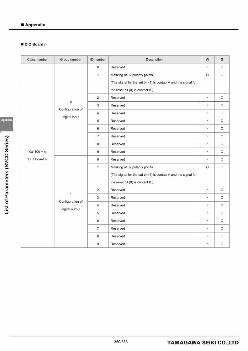
350/388
Appendix
Appendix
List
of P
aram
eter
s (S
VCC
Ser
ies)
DIO Board n
Class number Group number ID number Description W S
0 Reserved
1 Masking of 32 polarity points
(The signal for the set bit (1) is contact A and the signal for
the reset bit (0) is contact B.)
2 Reserved
3 Reserved
4 Reserved
5 Reserved
6 Reserved
7 Reserved
8 Reserved
0
Configuration of
digital input
9 Reserved
0 Reserved
1 Masking of 32 polarity points
(The signal for the set bit (1) is contact A and the signal for
the reset bit (0) is contact B.)
2 Reserved
3 Reserved
4 Reserved
5 Reserved
6 Reserved
7 Reserved
8 Reserved
0x1100 + n
DIO Board n
1
Configuration of
digital output
9 Reserved

351/388
Appendix
List
of P
aram
eter
s (S
VCC
Ser
ies)
Appendix
AIO CH n
Class number Group number ID number Description W S
0 Reserved
1 Reserved
2 Reserved
3 Reserved
4 Reserved
5 Reserved
6 Reserved
7 Reserved
8 Reserved
0
Configuration of
analog input
9 Reserved
0 Reserved
1 Reserved
2 Reserved
3 Reserved
4 Reserved
5 Reserved
6 Reserved
7 Reserved
8 Reserved
0x1200 + n
AIO CH n
1
Configuration of
analog output
9 Reserved
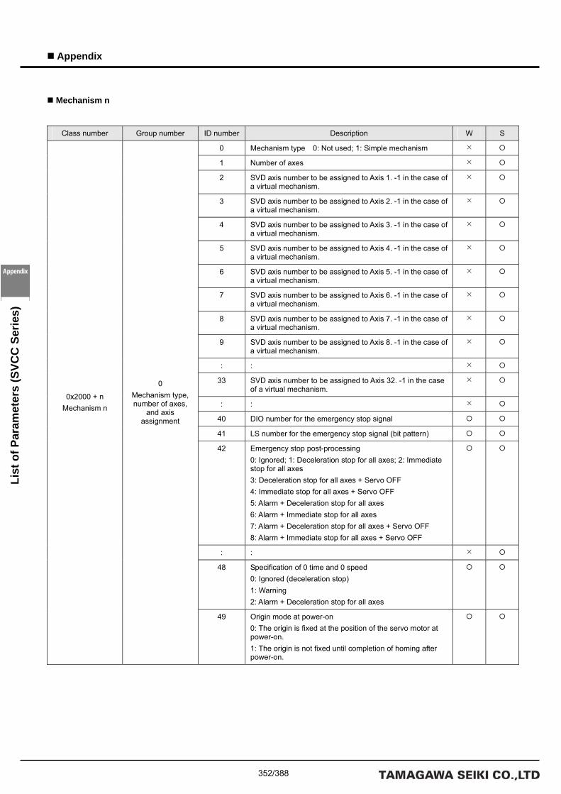
352/388
Appendix
Appendix
List
of P
aram
eter
s (S
VCC
Ser
ies)
Mechanism n
Class number Group number ID number Description W S
0 Mechanism type 0: Not used; 1: Simple mechanism
1 Number of axes
2 SVD axis number to be assigned to Axis 1. -1 in the case of a virtual mechanism.
3 SVD axis number to be assigned to Axis 2. -1 in the case of a virtual mechanism.
4 SVD axis number to be assigned to Axis 3. -1 in the case of a virtual mechanism.
5 SVD axis number to be assigned to Axis 4. -1 in the case of a virtual mechanism.
6 SVD axis number to be assigned to Axis 5. -1 in the case of a virtual mechanism.
7 SVD axis number to be assigned to Axis 6. -1 in the case of a virtual mechanism.
8 SVD axis number to be assigned to Axis 7. -1 in the case of a virtual mechanism.
9 SVD axis number to be assigned to Axis 8. -1 in the case of a virtual mechanism.
: :
33 SVD axis number to be assigned to Axis 32. -1 in the case of a virtual mechanism.
: :
40 DIO number for the emergency stop signal
41 LS number for the emergency stop signal (bit pattern)
42 Emergency stop post-processing 0: Ignored; 1: Deceleration stop for all axes; 2: Immediate stop for all axes 3: Deceleration stop for all axes + Servo OFF 4: Immediate stop for all axes + Servo OFF 5: Alarm + Deceleration stop for all axes 6: Alarm + Immediate stop for all axes 7: Alarm + Deceleration stop for all axes + Servo OFF 8: Alarm + Immediate stop for all axes + Servo OFF
: :
48 Specification of 0 time and 0 speed 0: Ignored (deceleration stop) 1: Warning 2: Alarm + Deceleration stop for all axes
0x2000 + n Mechanism n
0 Mechanism type, number of axes,
and axis assignment
49 Origin mode at power-on 0: The origin is fixed at the position of the servo motor at power-on. 1: The origin is not fixed until completion of homing after power-on.

353/388
Appendix
List
of P
aram
eter
s (S
VCC
Ser
ies)
Appendix
Class number Group number ID number Description W S
0 Axis type 0: Linear-motion axis; 1: Rotation axis; 2: Infinite linear motion axis; 3: Infinite rotation axis
1 Pulse rate numerator (unit: instruction unit [mm or deg])
2 Pulse rate denominator (unit: pulse)
3 Speed unit 0: 0.01% (with respect to the maximum rotation speed of the motor)
1: Instruction unit (per second); 2: min-1 [rpm]
4 Speed limit (unit: speed unit)
5 Processing when the maximum speed is exceeded 0: Ignored; 1: Deceleration stop; 2: Immediate stop; 3: Clamp 4: Warning + Clamp; 5: Alarm + Deceleration stop 6: Alarm + Immediate stop
6 Forward direction soft limit (unit: instruction unit)
7 Processing when the forward direction soft limit is exceeded 0: Ignored; 1: Deceleration stop; 2: Alarm + Deceleration stop)
8 Reverse direction soft limit (unit: instruction unit)
9 Processing when the reverse direction soft limit is exceeded 0: Ignored; 1: Deceleration stop; 2: Alarm + Deceleration stop)
10 DIO number for the forward direction stroke limit
11 LS number for the forward direction stroke limit (bit pattern)
12 Processing when the forward direction stroke limit is exceeded 0: Ignored; 1: Deceleration stop; 2: Immediate stop 3: Alarm + Deceleration stop; 4: Alarm + Immediate stop
13 DIO number for the reverse direction stroke limit
14 LS number for the reverse direction stroke limit (bit pattern)
15 Processing when the reverse direction stroke limit is exceeded 0: Ignored; 1: Deceleration stop; 2: Immediate stop 3: Alarm + Deceleration stop; 4: Alarm + Immediate stop
16 DIO number for the home sensor signal
17 LS number for the home sensor signal (bit pattern)
18 Reserved
19 Reserved
20 Infinite length axis coordinate reset (unit: instruction unit)
: :
: :
0x2000 + n Mechanism n
j Axis j
49 Reserved

354/388
Appendix
Appendix
List
of P
aram
eter
s (S
VCC
Ser
ies)
Class number Group number ID number Description R/W S
0 Interpolation period (unit: usec)
1 SVD monitoring period (unit: usec)
2 Reserved
: :
: :
0x2000 + n
Mechanism n
50
Motion control
49 Reserved
Task-Related Parameters
Class number Group number ID number Description R/W S
0 Number of global variables
1 Number of network variables 1
2 Number of network variables 2
3 Number of network variables 3
4 Number of network variables 4
5 Number of network variables 5
6 Number of network variables 6
7 Number of network variables 7
8 Number of network variables 8
9 Reserved
10 Reserved
11 Reserved
12 Reserved
13 Reserved
14 Reserved
15 Reserved
16 Reserved
17 Reserved
18 Reserved
0x4000
Task-related
parameters
0
Assignment of
global variables
19 Reserved

355/388
Appendix
List
of P
aram
eter
s (S
VCC
Ser
ies)
Appendix
Task n
Class number Group number ID number Description R/W S
0 Number of local variables
1 Number of stack variables
2 Reserved
3 Reserved
4 Reserved
5 Reserved
6 Reserved
7 Reserved
8 Reserved
0x4000 + n
Task n
0
Assignment of local
variables and stack
variables
9 Task stop processing in the event of an alarm
0: Stop the task in the event of an alarm
1: Do not stop the task in the event of an alarm

356/388
Appendix
Appendix
List
of P
aram
eter
s (S
VCC
Ser
ies)

357/388
Appendix
List
of P
aram
eter
s (S
VCC
Ser
ies)
Appendix
List of Monitor Items
(A) SVCC Series
System-Related Monitor Items
Class number Group number ID number Description
0 Hardware type (first 4 characters)
1 Hardware type (second 4 characters)
2 Hardware type (third 4 characters)
3 Hardware type (fourth 4 characters)
4 Software type (first 4 characters)
5 Software type (second 4 characters)
6 Software type (third 4 characters)
7 Software type (fourth 4 characters)
8 Version information (first 4 characters)
9 Version information (second 4 characters)
10 TA number for the product model
11 N number for the product model
12 E number for the product model
13 Serial number (first 4 characters)
0x0010
System-related
monitor items
0
System information
14 Serial number (second 4 characters)

358/388
Appendix
Appendix
List
of P
aram
eter
s (S
VCC
Ser
ies)
SVD-Related Monitor Items
Class number Group number ID number Description
0 Present instructed position of SVD Axis 1 (unit: pulse)
1 Present actual position of SVD Axis 1 (unit: pulse)
2 Present instructed position of SVD Axis 2 (unit: pulse)
3 Present actual position of SVD Axis 2 (unit: pulse)
0x1000
SVD-related
monitor items
0
Present position of
each axis
: :
Class number Group number ID number Description
0 Present instructed speed of SVD Axis 1 (unit: rpm)
1 Present actual speed of SVD Axis 1 (unit: rpm)
2 Present instructed speed of SVD Axis 2 (unit: rpm)
3 Present actual speed of SVD Axis 2 (unit: rpm)
0x1000
SVD-related
monitor items
1
Present speed of
each axis
: :
Class number Group number ID number Description
0 Present instructed electric current of SVD Axis 1 (unit: 0.01 A)
1 Present actual electric current of SVD Axis 1 (unit: 0.01 A)
2 Present instructed electric current of SVD Axis 2 (unit: 0.01 A)
3 Present actual electric current of SVD Axis 2 (unit: 0.01 A)
0x1000
SVD-related
monitor items
2
Present electric
current of each axis
: :

359/388
Appendix
List
of P
aram
eter
s (S
VCC
Ser
ies)
Appendix
Class number Group number ID number Description
0 SVD Axis 1 servo status
1 SVD Axis 1 alarm code
2 SVD Axis 2 servo status
3 SVD Axis 2 alarm code
0x1000
SVD-related
monitor items
3
Present status of
each axis
: :
Class number Group number ID number Description
0 Present instructed position of SVD Axis 1 (unit: pulse)
1 Present actual position of SVD Axis 1 (unit: pulse)
2 Present actual speed of SVD Axis 1 (unit: rpm)
3 Present actual electric current of SVD Axis 1 (unit: 0.01 A)
4 SVD Axis 1 servo status
5 SVD Axis 1 alarm code
6 Present actual position of SVD Axis 1 (unit: pulse with no origin offset)
7 Present instructed position of SVD Axis 2 (unit: pulse)
8 Present actual position of SVD Axis 2 (unit: pulse)
9 Present actual speed of SVD Axis 2 (unit: rpm)
10 Present actual electric current of SVD Axis 2 (unit: 0.01 A)
11 SVD Axis 2 servo status
12 SVD Axis 2 alarm code
13 Present actual position of SVD Axis 2 (unit: pulse with no origin offset)
: :
: :
49 Present instructed position of SVD Axis 8 (unit: pulse)
50 Present actual position of SVD Axis 8 (unit: pulse)
51 Present actual speed of SVD Axis 8 (unit: rpm)
52 Present actual electric current of SVD Axis 8 (unit: 0.01 A)
53 SVD Axis 8 servo status
54 SVD Axis 8 alarm code
0x1000
SVD-related
monitor items
100
Data for 8 SVD
Axes
55 Present actual position of SVD Axis 8 (unit: pulse with no origin offset)

360/388
Appendix
Appendix
List
of P
aram
eter
s (S
VCC
Ser
ies)
SVD Axis n
Class number Group number ID number Description
0 Present instructed position of SVD Axis n (unit: pulse)
1 Present actual position of SVD Axis n (unit: pulse)
2 Present instructed speed of SVD Axis n (unit: rpm)
3 Present actual speed of SVD Axis n (unit: rpm)
4 Present instructed electric current of SVD Axis n (unit: 0.01 A)
5 Present actual electric current of SVD Axis n (unit: 0.01 A)
6 SVD Axis n servo status
7 SVD Axis n alarm code
0x1000 + n
SVD Axis n
0
Data for SVD Axis
n
8 Present actual position of SVD Axis n (unit: pulse with no origin offset)
Class number Group number ID number Description
0 SVD Axis n version information
1 SVD Axis n serial number
2 SVD Axis n internal data monitor
3 SVD Axis n driver temperature (0.1°C)
0x1000 + n
SVD Axis n
1
System information
for SVD Axis n
4 Driving power voltage for SVD Axis n (0.1 V)
Class number Group number ID number Description
0 Internal data 0
1 Internal data 1
: :
0x1000 + n
SVD Axis n
0x0A
Internal data list ①
for SVD Axis n 49 Internal data 49
Class number Group number ID number Description
0 Internal data 50
1 Internal data 51
: :
0x1000 + n
SVD Axis n
0x0B
Internal data list ②
for SVD Axis n 49 Internal data 99
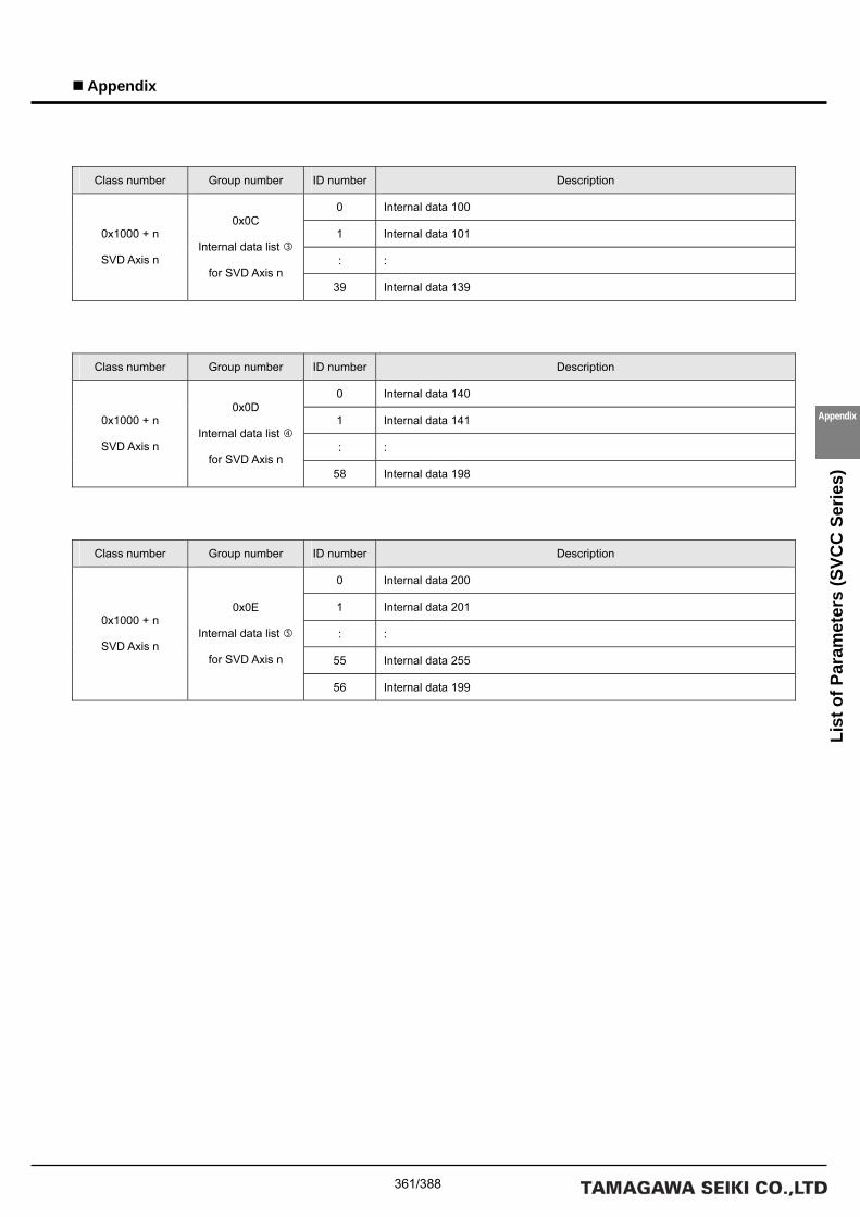
361/388
Appendix
List
of P
aram
eter
s (S
VCC
Ser
ies)
Appendix
Class number Group number ID number Description
0 Internal data 100
1 Internal data 101
: :
0x1000 + n
SVD Axis n
0x0C
Internal data list
for SVD Axis n 39 Internal data 139
Class number Group number ID number Description
0 Internal data 140
1 Internal data 141
: :
0x1000 + n
SVD Axis n
0x0D
Internal data list
for SVD Axis n 58 Internal data 198
Class number Group number ID number Description
0 Internal data 200
1 Internal data 201
: :
55 Internal data 255
0x1000 + n
SVD Axis n
0x0E
Internal data list
for SVD Axis n
56 Internal data 199

362/388
Appendix
Appendix
List
of P
aram
eter
s (S
VCC
Ser
ies)
DIO-Related Monitor Items
Class number Group number ID number Description
0 DIO Board 1 input data
1 DIO Board 1 output data
2 DIO Board 2 input data
3 DIO Board 2 output data
4 DIO Board 3 input data
5 DIO Board 3 output data
6 DIO Board 4 input data
7 DIO Board 4 output data
0x1100
DIO-related
monitor items
0
DIO data
: :
DIO Board n
Class number Group number ID number Description
0 DIO Board n input data 0x1100 + n
DIO Board n
0
DIO data 1 DIO Board n output data
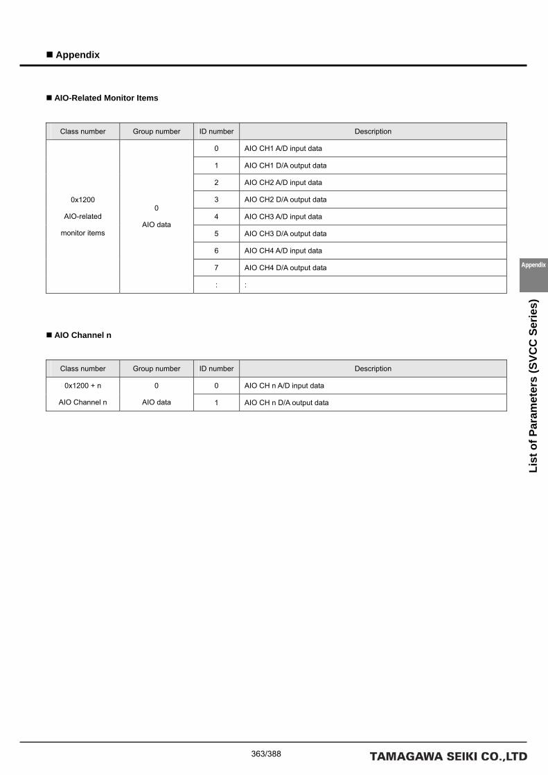
363/388
Appendix
List
of P
aram
eter
s (S
VCC
Ser
ies)
Appendix
AIO-Related Monitor Items
Class number Group number ID number Description
0 AIO CH1 A/D input data
1 AIO CH1 D/A output data
2 AIO CH2 A/D input data
3 AIO CH2 D/A output data
4 AIO CH3 A/D input data
5 AIO CH3 D/A output data
6 AIO CH4 A/D input data
7 AIO CH4 D/A output data
0x1200
AIO-related
monitor items
0
AIO data
: :
AIO Channel n
Class number Group number ID number Description
0 AIO CH n A/D input data 0x1200 + n
AIO Channel n
0
AIO data 1 AIO CH n D/A output data

364/388
Appendix
Appendix
List
of P
aram
eter
s (S
VCC
Ser
ies)
Mechanism-Related Monitor Items
Class number Group number ID number Description
0 Present status of Mechanism 1
1 Present status of Mechanism 2
0x2000
Mechanism-related
monitor items
0
Present status of
each mechanism : :
Mechanism Status
Bit number Description
0 Interpolation calculation in progress
1 Acceleration/deceleration in progress
2 Axis moving
3 Homing
4 Speed limit
5 Forward direction soft limit
6 Reverse direction soft limit
7
8 An alarm has been generated
9 A warning has been generated
10
11
12 Stop in the course of a move instruction
13 Forward direction stroke limit
14 Reverse direction stroke limit
15 Homing completed
: :

365/388
Appendix
List
of P
aram
eter
s (S
VCC
Ser
ies)
Appendix
Mechanism n
Class number Group number ID number Description
0 Present instructed position (unit: pulse)
1 Present actual position (unit: pulse)
2 Present instructed speed (unit: rpm)
3 Present actual speed (unit: rpm)
4 Present instructed electric current (unit: 0.01 A)
5 Present actual electric current (unit: 0.01 A)
6 Servo status
7 Servo alarm code
8 Present instructed position (instruction unit)
0x2000 + n
Mechanism n
j
Data for Axis j in
Mechanism n
9 Present actual position (instruction unit)
Class number Group number ID number Description
0 Mechanism n status
1 Mechanism n alarm number
2 Mechanism n alarm index
3 Mechanism n warning number
4 Mechanism n warning index
5 Mechanism n override first numerator
6 Mechanism n override first denominator
7 Mechanism n override second numerator
8 Mechanism n override second denominator
0x2000 + n
Mechanism n
100
Status of
Mechanism n
: :
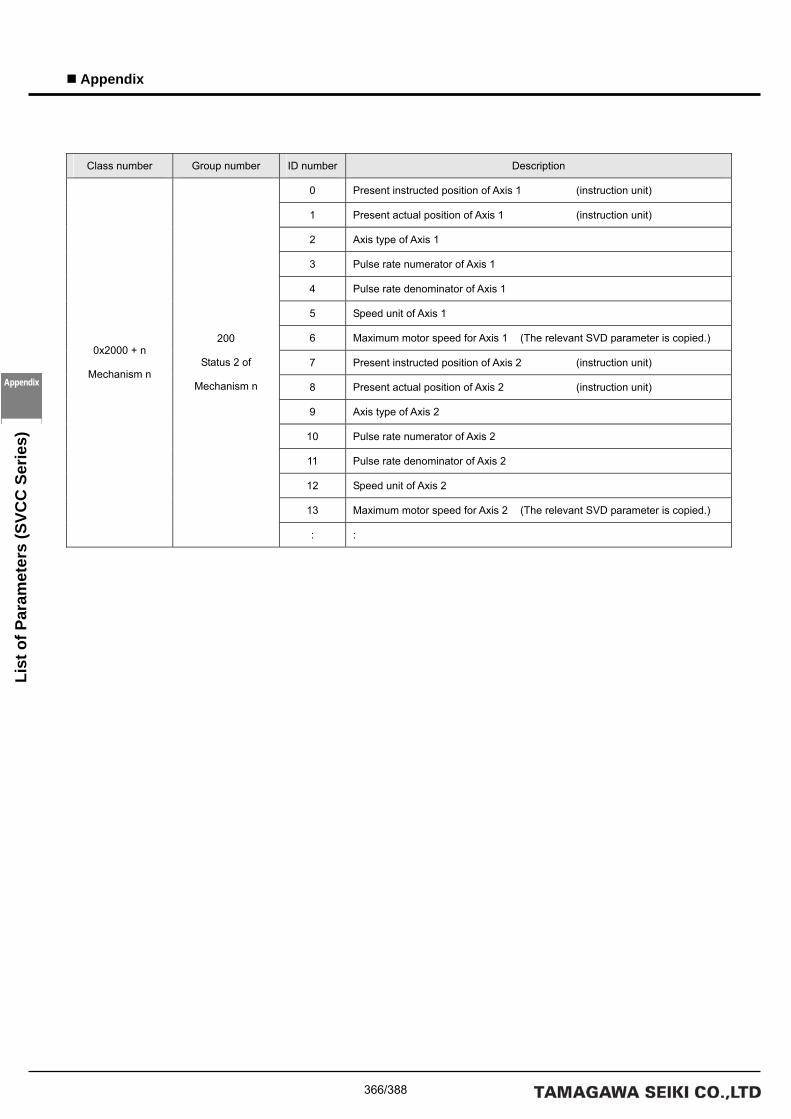
366/388
Appendix
Appendix
List
of P
aram
eter
s (S
VCC
Ser
ies)
Class number Group number ID number Description
0 Present instructed position of Axis 1 (instruction unit)
1 Present actual position of Axis 1 (instruction unit)
2 Axis type of Axis 1
3 Pulse rate numerator of Axis 1
4 Pulse rate denominator of Axis 1
5 Speed unit of Axis 1
6 Maximum motor speed for Axis 1 (The relevant SVD parameter is copied.)
7 Present instructed position of Axis 2 (instruction unit)
8 Present actual position of Axis 2 (instruction unit)
9 Axis type of Axis 2
10 Pulse rate numerator of Axis 2
11 Pulse rate denominator of Axis 2
12 Speed unit of Axis 2
13 Maximum motor speed for Axis 2 (The relevant SVD parameter is copied.)
0x2000 + n
Mechanism n
200
Status 2 of
Mechanism n
: :

367/388
Appendix
List
of P
aram
eter
s (S
VCC
Ser
ies)
Appendix
Task-Related Monitor Items
Class number Group number ID number Description
0 Present status of Task 0 (1: Being executed; 0: Stopped)
1 Present status of Task 1 (1: Being executed; 0: Stopped)
2 Present status of Task 2 (1: Being executed; 0: Stopped)
0x4000
Task-related
monitor items
0
Present status of
each task : :
Class number Group number ID number Description
0 Present status of Task 0 (1: Being executed; 0: Stopped)
1 Present step index of Task 0
2 Present stack pointer of Task 0
3 Present status of Task 1 (1: Being executed; 0: Stopped)
4 Present step index of Task 1
5 Present stack pointer of Task 1
6 Present status of Task 2 (1: Being executed; 0: Stopped)
7 Present step index of Task 2
8 Present stack pointer of Task 2
0x4000
Task-related
monitor items
0x8000
Present status 2 of
each task
: :

368/388
Appendix
Appendix
List
of P
aram
eter
s (S
VCC
Ser
ies)

369/388
Appendix
Appendix
List
of E
rror
Cod
es
List of Error Codes
SVC Error Definitions
An SVC error code consists of 8 digits. The first two digits indicate the major classification of the error and the last two digits
indicate the error code. The two digits after the major classification code indicate the task number and the next two digits after
that indicate the axis number, which may be omitted depending on the error content.
The following figure indicates the error code definition:

370/388
Appendix
Appendix
List
of E
rror
Cod
es
Motion Errors Error Classification: 01000000
Error code Error name Cause Action to be taken Error processing
01 Driver alarm input
Refer to the driver error code. Refer to the driver operation manual. All tasks stop.
Deceleration stop
performed for all axes.
(The driver performs
stop processing for
the axis that
generated the alarm.)
11 Forward direction soft
limit
The forward direction soft limit was
reached.
For an alarm to be output, this parameter
must be set accordingly.
Check the value set for the soft limit and
the task.
All tasks stop.
Deceleration stop
performed for all axes.
12 Reverse direction soft
limit
The reverse direction soft limit was
reached.
For an alarm to be output, this parameter
must be set accordingly.
Check the value set for the soft limit and
the task.
All tasks stop.
Deceleration stop
performed for all axes.
13 Excessive speed
The speed limit was reached. For an
alarm to be output, this parameter must
be set accordingly.
Check the value set for the speed limit,
the speed unit parameter, and the task.
All tasks stop.
Deceleration stop
performed for all axes.
14 Forward direction over
travel
The forward direction limit LS signal was
detected. For an alarm to be output, this
parameter must be set accordingly.
Check the forward direction limit LS signal
and the task.
All tasks stop.
Immediate or
deceleration stop
performed for all axes.
15 Reverse direction over
travel
The reverse direction limit LS signal was
detected. For an alarm to be output, this
parameter must be set accordingly.
Check the reverse direction limit LS signal
and the task.
All tasks stop.
Immediate or
deceleration stop
performed for all axes.
16 Emergency stop
switch input
The emergency stop switch was
activated. For an alarm to be output, this
parameter must be set accordingly.
Reset the emergency stop switch. All tasks stop.
Immediate or
deceleration stop
performed for all axes.

371/388
Appendix
Appendix
List
of E
rror
Cod
es
Task Errors Error Classification: 02000000
Error code Error name Cause Action to be taken Error processing
01 Division by 0
Division by 0 was performed by an
operation instruction.
Check the argument of the operation
instruction.
All tasks stop.
Deceleration stop
performed for all axes.
02 Operation overflow
The results of the operation instruction
overflowed.
Check the argument of the operation
instruction.
All tasks stop.
Deceleration stop
performed for all axes.
03 Excessive rotation
The rotation specified for the rotate
instruction is too large.
Check the argument of the ROT
command.
All tasks stop.
Deceleration stop
performed for all axes.
04 Excessive shift
The shift specified for the shift instruction
is too large.
Check the argument of the SHIFT
command.
All tasks stop.
Deceleration stop
performed for all axes.

372/388
Appendix
Appendix
List
of E
rror
Cod
es
Error code Error name Cause Action to be taken Error processing
11 Wait level
specification error
Specification for the SETWAIT command
wait level is invalid.
Check the argument of the SETWAIT
command.
All tasks stop.
Deceleration stop
performed for all axes.
12 Override-type
specification error
Specification for the override type in the
SETOVR or GETOVR command is
invalid.
Check the override type. All tasks stop.
Deceleration stop
performed for all axes.
13 Override number
specification error
The override number for the SETOVR or
GETOVR command is invalid.
Check the override number. All tasks stop.
Deceleration stop
performed for all axes.
14 Override data
specification error
Specification for the override data in the
SETOVR command is invalid.
Check the override data. All tasks stop.
Deceleration stop
performed for all axes.
15 Post-stop processing
specification error
Specification for post-stop processing in
the STOP or STOPJ command is invalid.
Check the argument for post-stop
processing.
All tasks stop.
Deceleration stop
performed for all axes.
16 Stop request level
specification error
Specification for the stop request level in
the STOP or STOPJ command is invalid.
Check the argument for the stop request
level.
All tasks stop.
Deceleration stop
performed for all axes.

373/388
Appendix
Appendix
List
of E
rror
Cod
es
Error code Error name Cause Action to be taken Error processing
21 AIO number
specification error
A nonexistent AIO number was specified. Check the specification for the AIO
number.
All tasks stop.
Deceleration stop
performed for all axes.
22 DIO number
specification error
A nonexistent DIO number was specified. Check the specification for the DIO
number.
All tasks stop.
Deceleration stop
performed for all axes.
23 PASS point
specification error
An invalid PASS point was specified. Check the PASS point. All tasks stop.
Deceleration stop
performed for all axes.
24 Monitor number
specification error
A nonexistent monitor number was
specified.
Check the monitor number. All tasks stop.
Deceleration stop
performed for all axes.
25 Timer number
specification error
A nonexistent timer number was
specified.
Check the timer number. All tasks stop.
Deceleration stop
performed for all axes.
26 SVD number
specification error
A nonexistent SVD number was specified. Check the SVD number. All tasks stop.
Deceleration stop
performed for all axes.
27 Axis number
specification error
A nonexistent axis number was specified. Check the axis number. All tasks stop.
Stop performed for all
axes.
28 Mechanism number
specification error
A nonexistent mechanism number was
specified.
Check the mechanism number. All tasks stop.
Deceleration stop
performed for all axes.
29 Task number
specification error
A nonexistent task number was specified. Check the task number. All tasks stop.
Deceleration stop
performed for all axes.

374/388
Appendix
Appendix
List
of E
rror
Cod
es
Error code Error name Cause Action to be taken Error processing
31 Specification of 0
speed
The value 0 was specified for the speed
argument of the move instruction. For an
alarm to be output, this parameter must
be set accordingly.
Check the speed argument of the move
instruction.
All tasks stop.
Deceleration stop
performed for all axes.
32 Specification of 0 time
The value 0 was specified for the time
argument of the move instruction. For an
alarm to be output, this parameter must
be set accordingly.
Check the time argument of the move
instruction.
All tasks stop.
Deceleration stop
performed for all axes.
33 Excessive move
distance
The value for the position argument of the
move instruction is too great.
Check the position argument of the move
instruction.
All tasks stop.
Deceleration stop
performed for all axes.
34 Excessive speed
The value for the speed argument of the
move instruction is greater than the set
maximum speed.
Check the speed argument and the
maximum speed parameter of the move
instruction.
All tasks stop.
Deceleration stop
performed for all axes.
35 Acceleration factor
setting error
The value for the acceleration factor
argument of the move instruction is
invalid.
Check the acceleration factor argument of
the move instruction.
All tasks stop.
Deceleration stop
performed for all axes.
36
Excessive
acceleration/decelerati
on time constant
The value for the
acceleration/deceleration constant is
greater than the predetermined value.
Check the argument of the ACCSET
command.
All tasks stop.
Deceleration stop
performed for all axes.

375/388
Appendix
Appendix
List
of E
rror
Cod
es
Error code Error name Cause Action to be taken Error processing
41 Arc interpolation mode
specification error
The value for the mode argument of the
arc interpolation instruction is invalid.
Check the mode argument of the arc
interpolation instruction.
All tasks stop.
Deceleration stop
performed for all axes.
42
Arc interpolation
option specification
error
The value for the option argument of the
arc interpolation instruction is invalid.
Check the option argument of the arc
interpolation instruction.
All tasks stop.
Deceleration stop
performed for all axes.

376/388
Appendix
Appendix
List
of E
rror
Cod
es
Error code Error name Cause Action to be taken Error processing
81 Origin not yet fixed
A prohibited command was executed with
the origin not fixed.
Execute homing. All tasks stop.
Deceleration stop
performed for all axes.
82 Override set value
error
The override value is greater than 100%.
The value 0 was specified for the
denominator when the numerator and
denominator were set.
Check the argument of the SETOVR
command.
All tasks stop.
Deceleration stop
performed for all axes.
Clear the override
value.
83
Acceleration/decelerat
ion time constant
setting error
An attempt was made to change the
acceleration/deceleration time constant
while axis moving is in progress.
Check the ACCSET command. All tasks stop.
Deceleration stop
performed for all axes.
84 Infinite length axis
command error
A prohibited command was executed in
infinite axis mode.
Check the MOV-related commands for the
infinite length set axis.
All tasks stop.
Deceleration stop
performed for all axes.
85 Network command
error
A network command was executed for a
nonexistent device.
Check the network command. All tasks stop.
Deceleration stop
performed for all axes.
86
Homing instruction
servo ON
incompletion error
A homing instruction was executed before
the servo ON processing had been
completed.
Check the homing instruction. All tasks stop.
Deceleration stop
performed for all axes.

377/388
Appendix
Appendix
List
of E
rror
Cod
es
Error code Error name Cause Action to be taken Error processing
91 Monitor size
specification error
The monitor request size is greater than
the predetermined limit.
Check the number of monitor items to be
obtained in the MONGET instruction.
All tasks stop.
Deceleration stop
performed for all axes.
92 Parameter size
specification error
The parameter request size is greater
than the predetermined limit.
Check the number of parameters to be
obtained in the PRMGET instruction.
All tasks stop.
Deceleration stop
performed for all axes.
93 No return destination
The return destination of the subroutine is
not specified.
Check the RET instruction. All tasks stop.
Deceleration stop
performed for all axes.
94 Stack overflow
The stack overflowed. Check the nesting depth of the CALL
instruction.
All tasks stop.
Deceleration stop
performed for all axes.

378/388
Appendix
Appendix
List
of E
rror
Cod
es
System Errors Error classification: 03000000
Error code Error name Cause Action to be taken Error processing
21
SV-NET
communication error:
Request error
A command not defined in the SV-NET
was issued. “Cable defective,” “No
terminating resistor,” “Noise,” or the like
may be the cause.
Check the cabling. SV-NET
communication stops.
All tasks stop.
Deceleration stop
performed for all axes.
22
SV-NET
communication error:
Reception overrun
Data was overwritten before a received
message was read. “Cable defective,” “No
terminating resistor,” “Noise,” or the like
may be the cause.
Check the cabling. SV-NET
communication stops.
All tasks stop.
Deceleration stop
performed for all axes.
71 Control power supply
voltage drop
The voltage of the internal 5-V power
supply dropped to 4.5 V or lower. “Control
power supply capacity insufficient,”
“Noise,” or the like may be the cause.
Check the control power supply voltage,
wiring, and other possible causes.
SV-NET
communication stops.
All tasks stop.
Deceleration stop
performed for all axes.

379/388
Appendix
Appendix
List
of E
rror
Cod
es
Error code Error name Cause Action to be taken Error processing
91 Command memory
write error
Write to command memory failed.
“Flash memory failed” or the like may be
the cause.
Re-write the parameters.
If the error persists, initialize the
parameters.
SV-NET
communication stops.
All tasks stop.
Deceleration stop
performed for all axes.
92 Parameter write error
Write of parameters failed.
“Flash memory failed” or the like may be
the cause.
Re-write the parameters.
If the error persists, initialize the
parameters.
SV-NET
communication stops.
All tasks stop.
Deceleration stop
performed for all axes.
93 Alarm history error
The alarm history area has been
destroyed.
“Powered off during alarm history
re-writing,” “Flash memory failed,” or the
like may be the cause.
Initialize the parameters. SV-NET
communication stops.
All tasks stop.
Deceleration stop
performed for all axes.
94 Command memory
read error
The command memory has been
destroyed.
“Powered off during flash memory
writing,” “Flash memory failed,” or the like
may be the cause.
Rewrite the task from the SV
Programmer, save it to the flash memory,
turn the power off, and then turn it back on
again. If the error persists, initialize the
parameters.
SV-NET
communication stops.
All tasks stop.
Deceleration stop
performed for all axes.
95 Parameter read error
The parameters have been destroyed.
“Powered off during flash memory
writing,” “Flash memory failed,” or the like
may be the cause.
Rewrite the parameters from the SV
Programmer, save them to the flash
memory, turn the power off, and then turn
it back on again. If the error persists,
initialize the parameters.
SV-NET
communication stops.
All tasks stop.
Deceleration stop
performed for all axes.
: :
: : :
99 Flash memory error
Flash memory initialization failed.
“Powered off during flash memory
re-writing,” “Flash memory failed,” or the
like may be the cause.
Initialize the parameters. SV-NET
communication stops.
All tasks stop.
Deceleration stop
performed for all axes.

380/388
Appendix
Appendix
List
of E
rror
Cod
es
Network Errors Error Classification: 04000000
• RS232C Communication Errors Error Classification: 04010000
Error code Error name Cause Action to be taken Error processing
11
RS232C
communication
timeout
No RS232C response is returned.
“Parameter setting faulty,” “Cable
defective,” or the like may be the cause.
Check the RS232C communication
parameters.
All tasks stop.
Deceleration stop
performed for all axes.
21 Communication data
checksum error
A checksum error was found in the
received data. “Noise” or the like may be
the cause.
Check the cabling. All tasks stop.
Deceleration stop
performed for all axes.
31
Error code of
connected device
received
An error code was received from the
connected device. “Parameter setting
faulty,” “Noise,” or the like may be the
cause.
Check the RS232C communication
parameters and cabling.
All tasks stop.
Deceleration stop
performed for all axes.
81 Parity error
A parity error was found in the received
data. “Parameter setting faulty,” “Noise,”
or the like may be the cause.
Check the RS232C communication
parameters and cabling.
All tasks stop.
Deceleration stop
performed for all axes.
82 Framing error
A framing error was found in the received
data. “Parameter setting faulty,” “Noise,”
or the like may be the cause.
Check the RS232C communication
parameters and cabling.
All tasks stop.
Deceleration stop
performed for all axes.
83 Overrun error
An overrun error occurred. “Parameter
setting faulty,” “Noise,” or the like may be
the cause.
Check the RS232C communication
parameters and cabling.
All tasks stop.
Deceleration stop
performed for all axes.

381/388
Appendix
Appendix
List
of E
rror
Cod
es
Error code Error name Cause Action to be taken Error processing
91 DMA address error
An address error occurred during DMA
transfer. “Noise” or the like may be the
cause.
Check the cabling. All tasks stop.
Deceleration stop
performed for all axes.
92 DMA NMI error
An NMI error occurred during DMA
transfer. “Noise” or the like may be the
cause.
Check the cabling. All tasks stop.
Deceleration stop
performed for all axes.

382/388
Appendix
Appendix
List
of E
rror
Cod
es

383/388
Index
Index
Inde
x
Index
A About label definition of the SV Programmer ................ 42
ABS............................................................................. 161
Absolute Position Move Instructions ..................... 10, 147
Absolute Position Move Target Set Instructions.......... 146
Acceleration/Deceleration in Progress .......................... 18
ACCSET ..................................................................... 152
Actual Electric Current Supervisory Program.............. 121
Actual Position Supervisory Program.......................... 123
ADD ............................................................................ 162
AIN.............................................................................. 215
ALMRST ..................................................................... 151
AND ............................................................................ 167
AO[*] ............................................................................. 48
AOUT.......................................................................... 214
Arc Interpolation Instruction ........................................ 126
Argument List Grid ........................................................ 24
Arithmetic Instructions................................................... 13
Axis Moving .................................................................. 18
B Bit Inspection Branch Instructions................................. 15
BITIN........................................................................... 218
BITOFF ....................................................................... 217
BITON......................................................................... 216
Branch Instructions ............................................... 15, 143
C CALL........................................................................... 197
Center Specified Arc Interpolation Individual Axis Move
................................................................................ 127
Command List............................................................. 141
Command Memory ......................................................... 3
Compound Move Commands ................................11, 124
COPY.......................................................................... 180
COS............................................................................ 176
D Data Acquisition Instructions .........................................14
Data Instructions....................................................13, 142
Debugging & Monitoring ..............................................108
Debugging Functions...................................................109
DECELA......................................................................225
Deceleration Stop/Immediate Stop ................................73
DECELM .....................................................................221
DEL Key Function..........................................................29
Details of Monitor Variables...........................................48
DI[*] ...............................................................................48
DIN ..............................................................................213
DIV ..............................................................................165
DO[*]..............................................................................48
DOUT ..........................................................................212
E END.............................................................................156
Error Definition ..............................................................58
Executing the Program................................................104
F FIELD1 ........................................................................172
FIELD2 ........................................................................173
File Pane .......................................................................25
FINRS..........................................................................260
G GETOVR .....................................................................341
GETRS........................................................................258
GETTID .......................................................................201
GETTST ......................................................................202
GETWAIT ....................................................................343
H Helical Move................................................................132
HOME..........................................................................240
HOME2........................................................................242

384/388
Index
Index
Inde
x
HOMEBUMP............................................................... 249
HOMECLR.................................................................. 246
HOMESET .................................................................. 244
HOMESET2 ................................................................ 245
HOMESV .................................................................... 251
Homing Instructions .................................................... 145
Homing Processing....................................................... 79
HOMINGE................................................................... 248
HOMINGS................................................................... 247
How to Specify a Label ................................................. 44
How to Specify a Variable ............................................. 45
How to Specify an Immediate ....................................... 44
I I/O Input Instructions..................................................... 21
I/O Instructions...................................................... 21, 144
I/O Output Instructions .................................................. 21
ID 158
Indirect Variable Reference....................................46, 116
INPOSA ...................................................................... 226
INPOSM...................................................................... 222
Insert Line/Delete Line Function ................................... 29
J JMP0........................................................................... 182
JMP1........................................................................... 183
JMPAND ..................................................................... 184
JMPAXIS..................................................................... 193
JMPBIT ....................................................................... 191
JMPDIO ...................................................................... 195
JMPEQ ....................................................................... 185
JMPGE ....................................................................... 190
JMPGT........................................................................ 188
JMPLE ........................................................................ 189
JMPLT......................................................................... 187
JMPMCH .................................................................... 194
JMPNE........................................................................ 186
JNPBIT ....................................................................... 192
JNPDIO....................................................................... 196
JOG Instructions ......................................................... 146
JOGJ ...........................................................................263
L List of Error Codes ......................................................369
List of Monitor Items ....................................................357
List of Monitor Variables ................................................47
List of Parameters .......................................................345
List of Reserved Words .................................................55
List of Shortcut Keys......................................................31
M MCH_ALM[*] .................................................................54
MCH_CPLS[*][*] ............................................................51
MCH_CPOS[*][*] ...........................................................52
MCH_FCUR[*][*] ...........................................................51
MCH_FPLS[*][*] ............................................................51
MCH_FPOS[*][*]............................................................52
MCH_FSPD[*][*] ............................................................51
MCH_FVEL[*][*] ............................................................51
MCH_JSTS[*][*].............................................................53
MCH_STS[*]..................................................................54
MCH_SVALM[*][*]..........................................................52
MCH_SVSTS[*][*]..........................................................52
Mechanism Number ........................................................7
MERGE .......................................................................177
MOD............................................................................166
MONGET.....................................................................179
Monitor Function.......................................................... 112
MOVAJ ........................................................................302
MOVAJA1....................................................................312
MOVAJA2....................................................................314
MOVAJBL....................................................................316
MOVAJCU ...................................................................308
MOVAJFS....................................................................306
MOVAJT ......................................................................304
MOVAJTW...................................................................310
MOVE..........................................................................338
Move Control Instructions............................................147
Move Direction of Move Instructions .............................10
Move Status Branch Instructions ...................................16

385/388
Index
Index
Inde
x
MOVIJ......................................................................... 320
MOVIJA1 .................................................................... 330
MOVIJA2 .................................................................... 332
MOVIJBL .................................................................... 334
MOVIJCU.................................................................... 326
MOVIJFS .................................................................... 324
MOVIJT....................................................................... 322
MOVIJTW ................................................................... 328
MUL ............................................................................ 164
N NEG............................................................................ 160
Network Errors............................................................ 380
Network Instructions ................................................... 145
NOP............................................................................ 150
NOT ............................................................................ 159
O OR .............................................................................. 168
Ordinary Branch Instructions ........................................ 15
ORGA ......................................................................... 227
ORGM......................................................................... 223
P PASS Instructions ................................................. 17, 144
PASSA ........................................................................ 224
PASSM ....................................................................... 220
Primary Speed Type.......................................................11
PRMGET .................................................................... 178
PRMSET2................................................................... 154
Procedure for Creating a Program................................ 61
Program Step Grid ........................................................ 24
R Relative Position Move Instructions ...................... 10, 147
Relative Position Move Target Set Instructions........... 146
Resetting of Set Axes...................................................... 9
RET............................................................................. 198
Right Angle Arc Interpolation Individual Axis Move ..... 126
ROT ............................................................................ 170
RUNRS........................................................................256
S Saving the Program..................................................... 113
SCALE.........................................................................174
Secondary Speed Type ................................................. 11
Servo Instructions..................................................19, 145
Servo On, Servo Off, and Servo Free Instructions ........19
Servo Parameter Instructions ........................................19
SETJOGJ ....................................................................262
SETMOVAJ .................................................................266
SETMOVAJA1.............................................................276
SETMOVAJA2.............................................................278
SETMOVAJBL.............................................................280
SETMOVAJCU ............................................................272
SETMOVAJFS.............................................................270
SETMOVAJT ...............................................................268
SETMOVAJTW............................................................274
SETMOVIJ ..................................................................284
SETMOVIJA1 ..............................................................294
SETMOVIJA2 ..............................................................296
SETMOVIJBL ..............................................................298
SETMOVIJCU .............................................................290
SETMOVIJFS..............................................................288
SETMOVIJT ................................................................286
SETMOVIJTW.............................................................292
SETOVR......................................................................340
SETRS ........................................................................259
Setting and resetting breakpoints ................................ 110
Setting the SVC Parameters .........................................62
Setup Axis Number..........................................................7
SETWAIT.....................................................................342
SHIFT..........................................................................171
Shortcut Menu for Child Tree Node (Split File) ..............25
Shortcut Menu for Parent Tree Node (Program File) .....25
Simple Wait Instruction..................................................20
SIN ..............................................................................175
Specifications of Motion Control ......................................4
Stack................................................................................3
STOP...........................................................................339

386/388
Index
Index
Inde
x
STOPJ ........................................................................ 344
STOPRS ..................................................................... 257
SUB ............................................................................ 163
Subroutie ........................................................................ 3
Subroutine Call ........................................................... 136
Subroutine Call Instructions .......................................... 16
SVC Error Definitions.................................................. 369
SVCUR ....................................................................... 236
SVD_ALM[*].................................................................. 50
SVD_CPLS[*]................................................................ 49
SVD_FCUR[*] ............................................................... 49
SVD_FPLS[*] ................................................................ 49
SVD_FVEL[*] ................................................................ 49
SVD_LOAD[*] ............................................................... 50
SVD_PWR[*]................................................................. 51
SVD_STS[*] .................................................................. 50
SVD_TEMP[*] ............................................................... 51
SVFREE ..................................................................... 232
SVMODE .................................................................... 233
SVOFF........................................................................ 231
SVON.......................................................................... 230
SVPRM2..................................................................... 237
SVVEL ........................................................................ 235
System Instructions..................................................... 141
T Tamagawa Motion Assembler Language .................... 1, 2
Target Position Set Instructions .................................... 10
Task ................................................................................ 2
Task Instruction ...........................................................136
Task Instructions..........................................................143
Task Monitor Function ................................................. 112
TASK_STS[*] .................................................................48
TEND...........................................................................205
Tertiary Speed Type.......................................................12
TIM[*].............................................................................48
TIME............................................................................208
Timer Instructions ..................................................20, 144
TMasM ........................................................................1, 2
TMoS...............................................................................2
TRESTART..................................................................203
TSTART.......................................................................200
TSTEP.........................................................................204
Types of PASS Instructions ...........................................18
U Undo/Redo Function .....................................................30
V Variable List Grid ...........................................................24
Variable Monitor Function............................................ 111
W WAIT ...........................................................................209
X XOR.............................................................................169

387/388
Index
Index
Inde
x

388/388
Index
Index
Inde
x


Please note that this manual may be changed without prior notice.
Manual number: MNL000389Y00
Company Web site: http://www.tamagawa-seiki.co.jp
SV-NET Web site: http://sv-net.tamagawa-seiki.com
Trading Company
TAMAGAWA TRADING CO.,LTD. Headquarters: 1-595-1 Haba-cho, Iida City, Nagano Prefecture, 395-0063 Japan
Eastern Japan Regional Headquarters (Responsible for: Niigata Pref., Nagano Pref., Yamanashi Pref., Kanagawa Pref. and areas eastward)
• Kita-Kanto Sales Office
338-001 3rd Floor, Yahata Bldg., 3-8-8 Kamiochiai, Chuo-ku, Saitama City, Saitama Prefecture, Japan
TEL (048) 851 - 4560 FAX (048) 851 - 4580
• Hachioji Sales Office
191-0011 2nd Floor, Central Green Bldg., 2-15-1 Hino-honmachi, Hino City, Tokyo, Japan
TEL (042) 581 - 9961 FAX (042) 581 - 9963
• Kanagawa Sales Office
252-0804 Rm. 302, Narita Bldg., 2-7-9 Shonandai, Fujisawa City, Kanagawa Prefecture, Japan
TEL (0466) 41 - 1830 FAX (0466) 41 - 1831
Western Japan Regional Headquarters (Responsible for: Toyama Pref., Gifu Pref., Aichi Pref., Shizuoka Pref. and areas westward)
• Nagoya Sales Office 486-0916 5-10 Hakko-cho, Kasugai City, Aichi Prefecture, Japan TEL (0568) 35 - 3533 FAX (0568) 35 - 3534 • Chubu Sales Office 444-0834 Rm. 303, Device Bldg., 210 Higashi-Arako, Hashira-cho, Okazaki
City, Aichi Prefecture, Japan TEL (0564) 71 - 2550 FAX (0564) 71 - 2551
• Hokuriku Sales Office
920-0036 Sion Furumura 301, 17-55 Motogiku-cho, Kanazawa City, Ishikawa Prefecture, Japan
TEL (076) 263 - 3731 FAX (076) 263 - 3732
• Osaka Sales Office 532-0011 Rm. 401, Osaka-hamamiya Bldg., 5-6-24 Nishi-Nakajima, Yodogawa-ku, Osaka City, Osaka, Japan
TEL (06) 6307 - 5570 FAX (06) 6307 - 5670
• Fukuoka Sales Office
812-0014 Maison MI306, 12-25 Hie-machi, Hakata-ku , Fukuoka City, Fukuoka Prefecture, Japan
TEL (092) 437 - 5566 FAX (092) 437 - 5533
Special Equipment Business Headquarters (Sales of aviation-, space- and defense-related equipment) • Tokyo Sales Office 144-0054 3-19-9 Shin-Kamata, Ota-ku, Tokyo, Japan TEL (03) 3731 - 2131 FAX (03) 3738 - 3134 • Kanagawa Sales
Office 252-0804 Rm. 302, Narita Bldg., 2-7-9 Shonandai, Fujisawa City,
Kanagawa Prefecture, Japan TEL (0466) 41 - 1830 FAX (0466) 41 - 1831
• Nagoya Sales Office 486-0916 5-10 Hakko-cho, Kasugai City, Aichi Prefecture, Japan TEL (0568) 35 - 3453 FAX (0568) 35 - 3534 • Osaka Sales Office 532-0011 Rm. 401, Osaka-hamamiya Bldg., 5-6-24 Nishi-Nakajima,
Yodogawa-ku, Osaka City, Osaka, Japan TEL (06) 6307 - 5580 FAX (06) 6307 - 3670
Overseas Sales Department SALES OFFICE : 1020, KEGA, IIDA, NAGANO PREF, 395 - 8520. JAPAN PHONE : 0265 - 56 - 5423 FAX : 0265 56 - 5427
Inquiries • Phone center: 1-595-1 Haba-cho, Iida City, Nagano Prefecture, 395-0063 Japan TEL (0265) 56 - 5421 ,5422 FAX (0265) 56 - 5426
Manufacturer
Tamagawa Seiki Co., Ltd. Headquarters & First Plant
395-8515 1879 Oyasumi, Iida City, Nagano Prefecture, Japan TEL (0265) 21 - 1800 (Main No.) FAX (0265) 21 - 1861
Second Plant 395-8520 1020 Kega, Iida City, Nagano Prefecture, Japan TEL (0265) 56 - 5411 FAX (0265) 56 - 5412 Third Plant 399-3303 3174-22 Motohshima Matsukawa-machi,
Shimoina-gun, Nagano Prefecture, Japan TEL (0265) 34 - 7811 FAX (0265) 34 - 7812
Hachinohe Plant 039-2245 1-3-47 Kita-Inter Kogyo-danchi, Hachinohe City, Aomori Prefecture, Japan
TEL (0178) 21 - 2611 FAX (0178) 21 - 2615
Fukuchi Factory, Hachinohe Plant
039-0811 1-1 Aza Kan-emonyama, Oaza Hoshioka, Nambu-cho, Sannohe-gun, Aomori Prefecture, Japan
TEL (0178) 60 - 1050 FAX (0178) 60 - 1155
Tokyo Plant 144-0054 3-19-9 Shin-Kamata, Ota-ku, Tokyo, Japan TEL (03) 3738 - 3233 FAX (03) 3738 - 3175