Embed Size (px)
Citation preview

SVM F27 Compact Compact heat meter
Users’ manual


3
Users’ manual
1 INSTALLATION................................................................................................... 5 1.1 CONNECTION AND MOUNTING........................................................................... 5
1.1.1 Flow part, mounting................................................................................. 5 1.1.2 Temperature sensors, mounting ............................................................... 5 1.1.3 Calculator, mounting ............................................................................... 6
1.2 START F27 ........................................................................................................ 7 1.3 CONNECTIONS................................................................................................... 8 1.4 TEST THE INSTALLATION................................................................................. 10
2 DIMENSIONS AND CLARIFICATIONS ........................................................ 11 2.1 CABLE OUTLETS.............................................................................................. 11
2.1.1 Cable length ........................................................................................... 11 2.2 DIMENSIONS CALCULATOR PART .................................................................... 11 2.3 DIMENSIONS FLOW PARTS............................................................................... 12
2.3.1 Threaded ................................................................................................ 12 2.3.2 Flanged .................................................................................................. 12
2.4 CLARIFICATIONS............................................................................................. 13 2.4.1 Momentary flow ..................................................................................... 13 2.4.2 Behavior at high flow ............................................................................. 13 2.4.3 Store data ............................................................................................... 13 2.4.4 Pulse value for pulses from pulse output................................................ 13
3 HANDLING.......................................................................................................... 15 3.1 MANEUVER IN THE DISPLAY SEQUENCE .......................................................... 15 3.2 DISPLAY SEQUENCE ........................................................................................ 16 3.3 ERROR CODES ................................................................................................. 17
4 SERVICE.............................................................................................................. 19 4.1.1 To set the calculator into service mode.................................................. 19 4.1.2 Exit service mode ................................................................................... 19
4.2 MANEUVER IN THE SERVICE MODE.................................................................. 20 4.3 SERVICE SEQUENCE TABLE ............................................................................. 21
4.3.1 FlexServ.exe ........................................................................................... 21 4.4 SERVICE FLOW PART ....................................................................................... 21
5 TEST ..................................................................................................................... 22 5.1 VERIFYING THE CALCULATOR......................................................................... 22
5.1.1 Set calculator in Test mode .................................................................... 22 5.2 TEST FLOW PART............................................................................................. 23
5.2.1 High frequency pulses ............................................................................ 23 5.2.2 Calibration flow part.............................................................................. 23
5.3 SEALS ............................................................................................................. 24

4
6 TECHNICAL DATA ........................................................................................... 25
6.1 TECHNICAL DATA FLOW PART......................................................................... 25 6.2 TECHNICAL DATA TEMPERATURE SENSORS..................................................... 25
6.2.1 Technical data TDA26 ........................................................................... 25 6.3 TECHNICAL DATA CALCULATOR ..................................................................... 26
6.3.1 Mains supplied ....................................................................................... 26 6.3.2 Temperature sensors .............................................................................. 26 6.3.3 Temperature range................................................................................. 26 6.3.4 Ambient temperature & Temperature class ........................................... 26 6.3.5 Flow sensor placing ............................................................................... 27 6.3.6 Maximum values for power .................................................................... 27 6.3.7 Dynamic behavior .................................................................................. 27 6.3.8 Data output interface ............................................................................. 27 6.3.9 Pulse output (either pulse output or pulse input on F27)...................... 28 6.3.10 Pulse input (either pulse input or pulse output on F27)......................... 28 6.3.11 Alarm output........................................................................................... 28
7 APPENDIX........................................................................................................... 29 7.1 DECIMAL SETTING FOR F27............................................................................. 29
7.1.1 Decimal setting for pulse inputs F27 ..................................................... 29 7.2 ARTICLENUMBER F27..................................................................................... 30
7.2.1 F27 Threaded ......................................................................................... 30 7.2.2 F27 Flanged........................................................................................... 31
5
1 Installation
1.1 Connection and mounting F27 may only be installed by trained professionals. We recommend installation according to common industry standards.
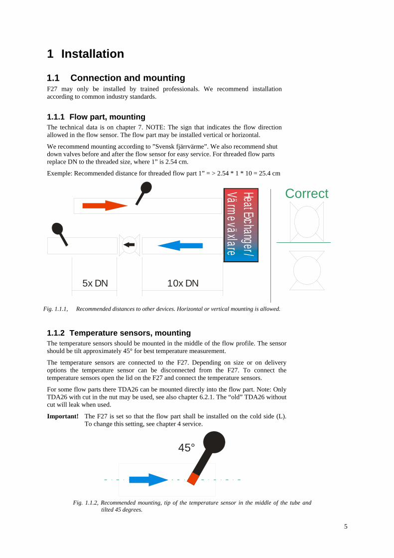
1.1.1 Flow part, mounting The technical data is on chapter 7. NOTE: The sign that indicates the flow direction allowed in the flow sensor. The flow part may be installed vertical or horizontal.
We recommend mounting according to ”Svensk fjärrvärme”. We also recommend shut down valves before and after the flow sensor for easy service. For threaded flow parts replace DN to the threaded size, where 1” is 2.54 cm.
Exemple: Recommended distance for threaded flow part 1” = > 2.54 * 1 * 10 = 25.4 cm
1.1.2 Temperature sensors, mounting The temperature sensors should be mounted in the middle of the flow profile. The sensor should be tilt approximately 45° for best temperature measurement.
The temperature sensors are connected to the F27. Depending on size or on delivery options the temperature sensor can be disconnected from the F27. To connect the temperature sensors open the lid on the F27 and connect the temperature sensors.
For some flow parts there TDA26 can be mounted directly into the flow part. Note: Only TDA26 with cut in the nut may be used, see also chapter 6.2.1. The “old” TDA26 without cut will leak when used.
Important! The F27 is set so that the flow part shall be installed on the cold side (L). To change this setting, see chapter 4 service.
45°
Fig. 1.1.2, Recommended mounting, tip of the temperature sensor in the middle of the tube and tilted 45 degrees.
Fig. 1.1.1, Recommended distances to other devices. Horizontal or vertical mounting is allowed.
Correct
5x DN 10x DN
Heat Exchanger /Värmeväxlare

6
F27
1.1.3 Calculator, mounting The calculator part of the F27 can be rotated in 90 degrees on the flow part. F27 robust construction allows any positioning of the calculator part on the flow part, on top, bottom or at the side.
The fastening device can be removed and can be used to wall mount the calculator part of the F27. The pulse cable is the cable between the flow part and the calculator part and is approximately 1 meter. This cable may not be cut or in other way changed.
Remove the rail fastener from the flow part. This can be used to fasten the calculator part on a wall
Loop to hook the calculator part on the wall
To get the best angle rotate the calculator part in 90 degrees
Fig. 1.1.3b, Wall mount the calculator part on the F27
Fig. 1.1.3a, Calculator part can be rotated on the flow part

7
1.2 Start F27 The F27 is delivered in transport mode. This means that the calculator is in a sleep mode, no measurements are done from the calculator. This mode is indicated with a “NO” in the upper left corner of the display. To start the F27 hold the display button in five seconds, until the “no” disappears. Operating, normal mode is indicated with ”10” in the display.
In service mode some settings in the calculator can be altered, see also chapter 4.
NOTE: The calculator must be set in normal mode before finishing the installation.
Fig. 1.2c, NOT normal mode, never leave calculator in this mode.
Top, transport mode middle, Service mode below, Testmode
Wrong
Fig. 1.2b, Normal mode, the F27 measures and calculates energy. The F27 must be set in this mode before finishing the installation According to EN1434 the calculator must clearly indicate the decimal setting. This is done in F27 by blinking digits
Correct Blinking digits
Fig. 1.1a, Display shows transport mode

8
1.3 Connections The connection terminals are placed safely inside the F27.
When the F27 is mains supplied a 1.5 [m] mains cable is delivered with the heat meter.
3 4M-BUSP1 0 P2
A1 B1 AL+
K5
K3
S1
PinPout S1K6
P1 - Energy output / input 1 ”+”0 - Common ”–” P2 - Volume output / input 2 ”+”
M-Bus utgång (Galvanisk isolerad)
S1 – Jumpers to set pulse output to pulse input
One or both outputs can be changed Node Jumpers are always set to
pulse output
How to description; Setting the jumpers for P1 and P2.
Temper-ature sensors HOT (H)
Temper-ature sensors Cold (L)
Fig. 1.3a, Connection terminal F27
Fig. 1.3b, Open the F27 and unhook the pulse adapter board in order to reach the terminals better.

9
1.3.1.1 Symbol description Symbol Description 3 4M-BUS
M-Bus
P1 0 P2 P1 = Pulse output 1 Energy (pulse input 1) ”+” 0 = common ”-” P2 = Pulse output 2 Volume (Pulse input 2) ”+”
Temperature sensor Hot (H)
Temperature sensor Cold (L)
A1 B1 Input/output options AL+
Alarm output
PinPout S1
Jumper setting description
S1 Jumpers for setting pulse output to input
K3 Connection mains board / battery board
K5 Connection to flow part
1.3.1.2 Jumpers pulse input / pulse output F27 has two pulse outputs when delivered. These outputs can be changed to one or two inputs.
Setting Description
S1
P1 = Pulse output (energy) P2 = Pulse output (volume)
S1
P1 = Pulse output (energy) P2 = Pulse input 2 (seq. ”14”)
S1
P1 = Pulse input 1 (seq. ”13”) P2 = Pulse input 2 (seq. ”14”)
S1
P1 = Pulse input 1 (seq. ”13”) P2 = Pulse output (volume)
3 4P1 0 P2
A1 B1
K5
K3
S1
PinPout S1K6
S1

10
1.4 Test the installation When the calculator is correctly installed a few simple installation test can be preformed to verify the function of the F27.
• Check the pulse indicator. • Check temperature is show in display • Check pulse value setting • Check flow part placing • Check for any error codes
Fig. 1.4c, Seq., “22” temperature hot (H) and “23” cold (L)
Fig. 1.4d, Seq. “24”, temperature difference
Fig. 1.4c, Seq. “63” pulse value and “64” placing
Fig. 1.4b, Seq. “15” error codes
Fig. 1.4a, Flow pulses are indicated with a square

11
2 Dimensions and clarifications
2.1 Cable outlets
2.1.1 Cable length Cable type Length [m] Ultrasonic cable, cable between the calculator part and the flow part (may not be cut)
1
Mains cable (only in 230V supplied F27) 1.5
2.2 Dimensions calculator part Dimmensions in [mm].
SERVICE
TEST SAVEDATA
(4x) Ø9CablesØ4...Ø5.5
CablesØ6.5
Cable outlets
Fig. 2.1, Cable outlets and possible cable size in F27
Fig. 2.2, Dimensions F27 calculator part
SERVICE
12060
112
75
67Ø7.8

12
2.3 Dimensions flow parts
2.3.1 Threaded Typ Qp
[m³/h] G A b h
0 0.6 G3/4” 110 - 77 1 1.5 G3/4” 110 - 77 2 0.6 G1” 130 - 77 3 1.5 G1” 130 - 77 4 2.5 G1” 130 - 74 5 3.5 G1¼” 260 51 111 6 6 G1¼” 260 51 111 7 10 G2” 300 68 108
2.3.2 Flanged
Typ Qp [m³/h]
DN a b h Øc Ød HCD
Øe Ant. Skruv
hål f g
A 3.5 25 260 51 111 115 85 14 4 68 18 B 6 25 260 51 111 115 85 14 4 68 18 C 10 40 300 48 108 150 110 18 4 88 18 D 15 50 270 46 106 165 125 18 4 102 20 E 25 65 300 52 112 185 145 18 8 122 22 F 40 80 300 56 116 200 160 18 8 138 24 G 60 100 360 68 128 235 190 22 8 158 24
a g
h
f
Øe
b
ØdØc
a
h
G
b

13
2.4 Clarifications
2.4.1 Momentary flow The momentary values are displayed in sequence “20”. Momentary flow is in seq. “21”. This calculation is secondary. The time base is 4 seconds and can be altered.
2.4.2 Behavior at high flow When the flow is higher than qs (upper flow limit) the flow part will give an output until 2.8x qn (permanent flow) and then send an output that equals Kv. See also technical data for Kv.
2.4.3 Store data All meter data is saved in a ”EEProm” at day shift. When service shall be preformed on the F24 (e.g. change of battery or other) the save data should be preformed. This procedure is done by short circuit the button “save data”. The data save is indicated in the display under seq. “15” with “080”.
2.4.4 Pulse value for pulses from pulse output
Kvqp Flow [m3/h]
Puls
es
Fig. 2.4.2, At flow over 2.8x qn (Kv) the flow part emits pulses equal to Kv
SERVICE
TEST SAVEDATA
Mwhm³/h kW°Cm³
15 0000080
Fig. 2.4.3, Save meter data by short circut ”Save Data”, code ”080” will appear under seq. ”15”
PULSE
Fig. 2.4.4a, Seq. ”10” (energy), when the last digit increments one one pulse is emitted from the pulse output P1 (if jumpers are set for pulse outputs).
In the example the pulse value is 0.01 [MWh].
Mwhm³/h kW°Cm³
10 00002.38Mwhm³/h kW°Cm³
10 00002.39
Mwhm³/h kW°Cm³
11 000095.0Mwhm³/h kW°Cm³
11 000095.1
Fig. 2.4.4b, Seq. ”11” (volume) increments one pulse is emitted from P2.
Pulse value 0.1 [m3] in the example. The last digit and the unit decide the pulse value.


15
3 Handling
3.1 Maneuver in the display sequence F27 has an LCD-display where the stored information can be retrieved. The two upper digits in the display indicate the sequence. The left digit indicates in which sequence loop the display is in. Hold the button pressed to change sequence. Too toggle in the sequence press the display button until correct value is acquired.
The display returns to seq. “10” after 60 seconds of inactivity, in the normal mode.
Desciption of the display: 1. Sequence indicator 2. Square indicate flow pulse 3. Value, max 7 digits 4. Arrow point the correct unit for the value
1.
2.
4.
3.
F27
Optical interface
Push button
16xx
1110
xx20 xx
xx70
Fig.3.1, Hold to reach next sequence and push to toggle in the sequence
HOLD
PUSH
16
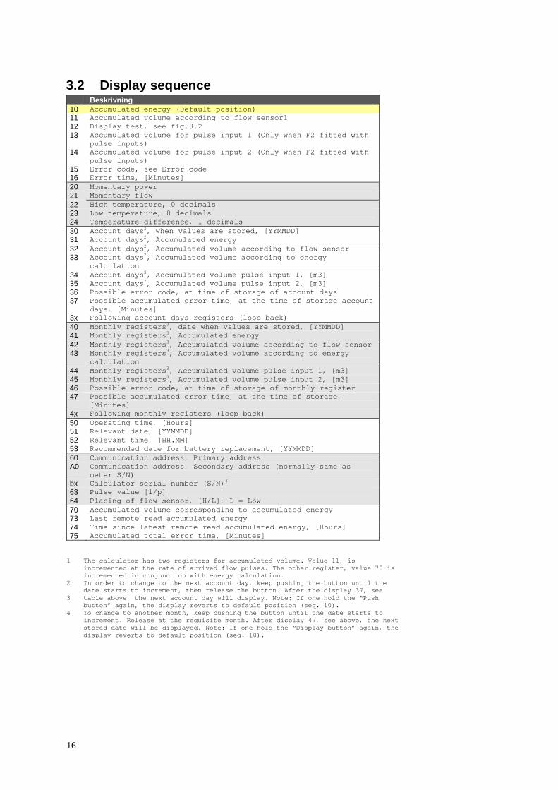
3.2 Display sequence Beskrivning 10 Accumulated energy (Default position) 11 Accumulated volume according to flow sensor1 12 Display test, see fig.3.2 13 Accumulated volume for pulse input 1 (Only when F2 fitted with
pulse inputs) 14 Accumulated volume for pulse input 2 (Only when F2 fitted with
pulse inputs) 15 Error code, see Error code 16 Error time, [Minutes] 20 Momentary power 21 Momentary flow 22 High temperature, 0 decimals 23 Low temperature, 0 decimals 24 Temperature difference, 1 decimals 30 Account days2, when values are stored, [YYMMDD] 31 Account days2, Accumulated energy 32 Account days2, Accumulated volume according to flow sensor 33 Account days2, Accumulated volume according to energy
calculation 34 Account days2, Accumulated volume pulse input 1, [m3] 35 Account days2, Accumulated volume pulse input 2, [m3] 36 Possible error code, at time of storage of account days 37 Possible accumulated error time, at the time of storage account
days, [Minutes] 3x Following account days registers (loop back) 40 Monthly registers3, date when values are stored, [YYMMDD] 41 Monthly registers3, Accumulated energy 42 Monthly registers3, Accumulated volume according to flow sensor 43 Monthly registers3, Accumulated volume according to energy
calculation 44 Monthly registers3, Accumulated volume pulse input 1, [m3] 45 Monthly registers3, Accumulated volume pulse input 2, [m3] 46 Possible error code, at time of storage of monthly register 47 Possible accumulated error time, at the time of storage,
[Minutes] 4x Following monthly registers (loop back) 50 Operating time, [Hours] 51 Relevant date, [YYMMDD] 52 Relevant time, [HH.MM] 53 Recommended date for battery replacement, [YYMMDD] 60 Communication address, Primary address A0 Communication address, Secondary address (normally same as
meter S/N) bx Calculator serial number (S/N)4 63 Pulse value [l/p] 64 Placing of flow sensor, [H/L], L = Low 70 Accumulated volume corresponding to accumulated energy 73 Last remote read accumulated energy 74 Time since latest remote read accumulated energy, [Hours] 75 Accumulated total error time, [Minutes]
1 The calculator has two registers for accumulated volume. Value 11, is
incremented at the rate of arrived flow pulses. The other register, value 70 is incremented in conjunction with energy calculation.
2 In order to change to the next account day, keep pushing the button until the date starts to increment, then release the button. After the display 37, see
3 table above, the next account day will display. Note: If one hold the “Push button” again, the display reverts to default position (seq. 10).
4 To change to another month, keep pushing the button until the date starts to increment. Release at the requisite month. After display 47, see above, the next stored date will be displayed. Note: If one hold the “Display button” again, the display reverts to default position (seq. 10).

17
3.3 Error codes Error codes are displayed in sequence ”15”. The three digits counted from the left combines the error code. The interpretation depends on the position. The error code can consist of more than one error.
Error code (1)
Description
1 Disconnected temperature sensor cold (L)* 2 Temperature sensor cold (L) short circuit 4 Disconnected temperature sensor hot (L)* 8 Temperature sensor cold (L) short circuit
Error code (2)
Description
1 Electronic error (contact service) 2 I2C error (contact service) 4 Low flow 8 Mains failure (only 230V supplied)
/ Save data (save data button)
Error code (3)
Description
1 Change battery 2 CPU error (contact service) 4 Error in flow part*
(Air in flow part/electronic error) 8 Not used
* Error codes that can appears in a not installed F27
Error codes that do not appear in the table is an combination of two or more error codes, see table below.
Example: Error code 5 at position 1 = > 1 + 4, temperature sensor hot (H) disconnected, temperature sensor cold (L) disconnected, probably temperature sensor not connected.
Error code Error code combination
3 1 + 2 5 1 + 4 6 2 + 4 7 1 + 2 + 4 9 1 + 8 A 2 + 8 B 1 + 2 + 8 C 4 + 8 D 1 + 4 + 8 E 1 + 2 + 4 + 8
Fig. 3.3a, Displaysequence “15” error codes are displayed here
1 2 3
Mwhm³/h kW°Cm³
15 00004c5Fig. 3.3b, Example 2 Error code “4c5” is shown
1. ”5” => 1+4 = Both temperature sensors disconnected.
2. ”C” => 4+8 = No 230V connected and low flow
3. ”4” = Error in flow part, probably air in flow part
This is a very common error in F27 that is not installed
Similar code battery supplied F27 is ”445”


19
4 Service A seal must be broken in order to set F27´s calculator part in service mode. The service mode can be accessed using a push button and a dull thin screwdriver, see below 4.1.1. To set the calculator back into the normal mode use the same procedure as setting the calculator in service mode. Service mode is indicated with “00” in the display.
Note Any changes made in the service mode will be permanet first when the next service sequence is reached. Example when time is changed hold the button pressed until changing the date is reached.
4.1.1 To set the calculator into service mode 1. Hold the “service button” pressed with a thin dull
screwdriver.
2. Hold the “service button” pressed and at the same time hold the “push button” pressed. Wait in 5 seconds
3. Release the “push button”.
4. First then release the ”service button”.
Changing of the display when entering the service mode:
Mwhm³/h kW°Cm³
2345.67810
Fig. 4.1b, normal mode
Mwhm³/h kW°Cm³
00 1130
Fig. 4.1c, Service mode is indicated with a ”0” on the left digit, a value digit is also blinking.
4.1.2 Exit service mode There are two way to exit the service mode
1. Use the same procedure as setting the calculator in service mode.
2. Hold the ”push button” pressed until the sequence reaches ”0A”. Then push the “push button” so that the value changes to “1” and HOLD the “push button” pressed.
2
3
1
4
Fig. 4.1, Set the calculator into service mode
20
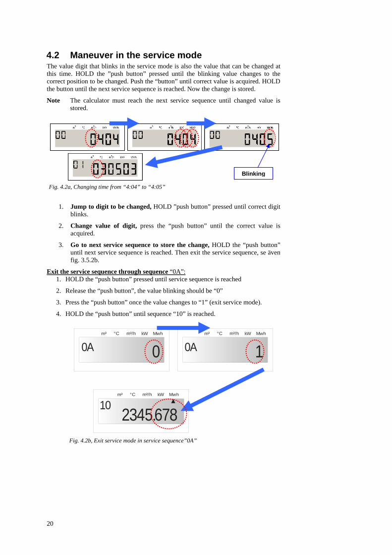
4.2 Maneuver in the service mode The value digit that blinks in the service mode is also the value that can be changed at this time. HOLD the ”push button” pressed until the blinking value changes to the correct position to be changed. Push the “button” until correct value is acquired. HOLD the button until the next service sequence is reached. Now the change is stored.
Note The calculator must reach the next service sequence until changed value is stored.
1. Jump to digit to be changed, HOLD ”push button” pressed until correct digit blinks.
2. Change value of digit, press the “push button” until the correct value is acquired.
3. Go to next service sequence to store the change, HOLD the “push button” until next service sequence is reached. Then exit the service sequence, se även fig. 3.5.2b.
Exit the service sequence through sequence “0A”: 1. HOLD the “push button” pressed until service sequence is reached
2. Release the “push button”, the value blinking should be “0”
3. Press the “push button” once the value changes to “1” (exit service mode).
4. HOLD the “push button” until sequence “10” is reached.
Fig. 4.2a, Changing time from “4:04” to “4:05”
Mwhm³/h kW°Cm³
0A 0Mwhm³/h kW°Cm³
0A 1
Mwhm³/h kW°Cm³
2345.67810
Blinking
Fig. 4.2b, Exit service mode in service sequence”0A”

21
4.3 Service sequence table
Service sequence
Description
00 Time, hhmm 01 Date, YYMMDD 02 Pulse value, 4 digits (no decimals) 03 Decimal placing, 0-4 04 Account day 1, MMDD 05 Account day 2, MMDD 06 Primary address (in 3 digits). ex. “5” is
set “005” in display. 07 Reset error time,
0 = Reset (standard) 1 = Do not reset error time
08 Flow part placing, 0 = Cold (L), STANDARD 1 = Hot (H)
09 Battery change date, YYMMDD. Do not change without consulting Metrima AB
0A Exit Service mode 1 = Exit service mode 0 = Return to “00”
Table 4.3, Service sequence, hh – hour, mm – minute, YY – Year, MM – Month, DD – Day
Note Wrong setting in the service mode can result in wrong calculation or measurements.
4.3.1 FlexServ.exe With a PC program ”FlexServ.exe” even more parameters can be changed, se ”service manual” for more information.
Note Wrong set calculator will measure and calculate wrong.
4.4 Service flow part The service on the flow part should be preformed by a certified test laboratory. For more instructions see the service manual.
Cleaning of the tube: 1. For small sizes, the two measuring sensor should be
removed. Then use a brush to clean the tube.
2. For larger sizes of the flow part, clean the flow part with a brush directly.
NOTE: This may only be preformed by trained qualified service personnel.
Fig. 4.3a, Service button
SERVICE
Service button
Push button
Fig. 4.3b, Push button
Two sensors
Fig. 4.4, Small flow parts the two measuring sensor must be removed before claning

22
5 Test
5.1 Verifying the calculator Verification of the calculator's measurement accuracy is undertaken in the test mode, where the energy value/flow sensor pulse is issued via the HF-output at the service adapter. For each flow sensor pulse, measurement takes place on the temperature sensors and a pulse burst corresponding to the measured energy of the meter is issued.
To test (verify) the measurement accuracy of the calculator by means of HF-pulses proceed as follows:
1. While short circuiting the test button with “Test key”, hold the “Push button” until the display mode changes.
2. The calculator now enters test mode. This is indicated by a flash symbol being displayed.
3. Connect fixed resistance for simulation of Pt100 via terminal block units Nos. 5-6 (flow) and 7-8 (return).
4. Connect a pulse generator via terminal block unit Nos. 10-11 (connection 11 is ground) in order to simulate flow sensor pulses. Note: Voltage level is max. 3V.
5. Connect an OPTO-head/interface with HF-pulse interface at the front.
6. Simulate a flow sensor pulse after which the meter issues an (approximately) 20 kHz pulse burst corresponding to 100*k*dt pulses via the HF-output. “k” is the energy factor. (kWh/°C/m3) and dt is the difference between simulated flow and return temperatures.
Example: Rf=138.50Ω (100.00°C), Rr=127.07Ω (70.00°C) => dt=30.00°C, k=1.141 gives 100*1.141*30 = 3423 pulses
7. The next flow sensor pulse can be sent immediately after the HF-pulse burst from the meter has been dispatched.
To leave test mode proceed as follows: 1. While short circuiting the test button hold the “Display Button”.
2. The calculator now enters operation mode.
3. Connect Optical head with HF-pulsinterface on front.
To verify (test) the measurement accuracy of the meter with help of the display, first set up connections in accordance with points 3 and 4 above for testing by means of HF-pulses. Testingis undertaken in the meter's operation mode. Proceed as follows:
1. Supply flow sensor pulses until the energy display is incremented one step.
2. Supply flow sensor pulses with a maximum frequency of 12 Hz until the display has been stepped appropriate numbers of steps.
3. Errors in testing decrease with the number of steps made during the test. If the meter is programmed for 1.0 liter/pulse and resolution for display of energy is 0.001MWh, this means that 10 steps on the display correspond to 288.85 pulses from the flow sensor with selected temperatures in accordance with the above. The testing error is maximum + - 1 pulse, which, in the example, corresponds to 0.35%.
5.1.1 Set calculator in Test mode To set the calculator into “test mode”. Short circuit the “test button” and at the same time press the push button, release the push button and then release the ”test button. The method is similar to setting the calculator into “service mode”, see chapter 4.1.
SERVICE
TEST SAVEDATA

23
5.2 Test flow part The PCB-board controls the flow part. Several selas are on the PCB-board that protects the different modes on the flow part.
5.2.1 High frequency pulses Breaking the seal (1) and short circuit the button will set the flow part into sending high frequence pulses. These pulses are equal to the flow and can be read through an Optical head. Using the PC-program “PappaWin” test results can be read from the flow part. For more detailed description see manual ”TKB3412c_engl.pdf”.
5.2.2 Calibration flow part Breaking seal (2) and short circuit the button will set the flow part into calibration mode. With an Optical head and using the PC-program “PappaWin” the flow part can be calibrated. In this mode the flow part also emits high frequency pulses. For more detailed instructions see ”TKB3412c_engl.pdf”.
Picture 6
SVM SVM
Placering av optohuvud
1 2

24
5.3 Seals 1. Installation seal 2. Electronic seal 3. Test seal calculator (inside calculator) 4. Service seal calculator 5. Calibration seal flow part 6. Service seal flow part 7. Flow part seal
SERVICESVM
TESTSVM
1
4 3
SVM
2
Fig. 5.3a, Seals F27 calculator
Fig. 5.3b, Seals F27 flow part
6 6 SVM SVM
56

25
6 Technical data
6.1 Technical data flow part Accuracy class 2* Environmental class C Metrological class 1:100 (dynamic range) Installation orientation Horizontal or Vertical Installation placing Return or supply Temperature range +10°C -- +130°C Max. temperature +150°C in max. 2000h Max. flow 2.8 x qp Medium Water * Qp 2.5 accuracy class 3
6.2 Technical data temperature sensors Temperature sensors are connected to the F27 when delivered. There can be different types of temperature sensors depending on the delivery order. For more technical information on the different temperature sensors, see documentation for that temperature sensor.
6.2.1 Technical data TDA26 Only TDA26 with a cut in the nut can be mounted directly into the flow part. The old type will cause a leakage.
Sensor type Pt100/Pt500 Resistance acc. to IEC751 Max RMS sensor current 8 [μA] Measuring range 0 - 140 [°C] Tolerance Class B Temp. difference 2 – 100 [°C] Temp. Step response 1.8 [s] Min. immersion depth 20 [mm] Pressure PN16 Dimensions Diameter 3.5 [mm] Length 26 [mm] Resistance (2-wire cable) 0,2955 [Ω] Cable length 2 [m] Cable type Silicone, PUR or PVC
Swedish SP SP WT 98:01 P 15 42 02 German PTB 22.70/99.06
Fig. 6.21, TDA26 Dimensions Only TDA26 with a cut in the nut can be used in V700 and F27 flow parts.
When used TDA26 without a cut in the nut there is a risk for lekage.
Sealing Cut
M10x1
Ø 3.5

26
6.3 Technical data calculator
6.3.1 Mains supplied Battery 3.6V – 18 Ah
10 years operation Mains 230V±10%, 45-65Hz,
battery 1 Ah as spare* * At mains failure the spare battery will automatically take charge. The flow
part will not be supplied from the spare battery
6.3.2 Temperature sensors Approved and matching pares type PT100 or PT500 are to be used. Maximum sensor current (RMS): 4μA
Calbe area [mm2]
Max. cable length for PT100 sensors [m]
0.22 2.5 0.50 5.0 0.75 7.5 1.50 15.0
6.3.3 Temperature range Temperature range 10 - 130°C (190°C) Temperature difference 2 – 120K
6.3.4 Ambient temperature & Temperature class F27 comply with the prerequisites for Environmental Class C according to EN1434.
Ambient temperature Storage/Transport
-20°C to +70°C
Ambient temperature operation
+5°C to +55°C

27
6.3.5 Flow sensor placing F22 can be configured for flow sensor placed in high or low end of the pipe (supply or return pipe). This is marked H = high or L = Low. In the display sequence “64.
6.3.6 Maximum values for power The values below are valid for energy unit [MWh] and standard decimal setting.
Pulse value [l/p]
Max. power [ MW ]
1.0 3.3 10.0 33.0 100.0 330.0 2.5 3.3 25.0 33.0 250.0 330.0
6.3.7 Dynamic behavior pulses is five (5) seconds or longer. If the time between pulses is less than five seconds, measurement takes place each five seconds. When the period between the flow sensor pulses exceeds 60 seconds, a measurement takes place every 60th second. For this measurement only the temperature is updated.
6.3.8 Data output interface M-Bus acc. EN1434-3
OPTO-interface (EN60870-5) and bus connection (terminal) galvanic isolated
L
H
Fig. 6.3.5, Flow part placing

28
6.3.9 Pulse output (either pulse output or pulse input on F27)
F22 is equipped with two pulse outputs as standard of the type ”Open collector” for energy (Pulse output 1) and volume (Pulse output 2).
Pulse output 1 (energy) Energy, one (1) pulse per display update in the energy register (seq. “10”).
Pulsutgång 2 (volym) Volume, one (1) pulse per display update in the flow register (seq. “11”).
The last digit and the unit decide the pulse value, see chapter 2.4.4.
Pulse duration [ms] 250 Voltage [V] 3 – 30 Max current [mA] 20
6.3.10 Pulse input (either pulse input or pulse output on F27)
F22 is equipped with two pulse inputs as standard. The pulse inputs can be used for measuring of other meter with pulse outputs, such as cold and hot water meters, gas, electricity meters and other meters. The pulse inputs can be set as volume registers. These registers accumulate the pulses into two volume registers with the value [m3].
Frequency [Hz] 12 Min. Pulse frequency [ms] 40 Max. Voltage [V] 3
6.3.11 Alarm output The F22 is equipped with one alarm output as standard of the type “Open collector”. The alarm output sends a pulse every hour as long as an error code exists. The pulse duration 250 [ms] for pulse and alarm output can be altered using the “FlexServ.exe” version 2 or higher in 125ms steps.
Alarm frequency when an error exists
Once every hour
Pulse length [ms] 250
+ 3V
Fig. 6.3.10, Schematics pulse input
7 Appendix
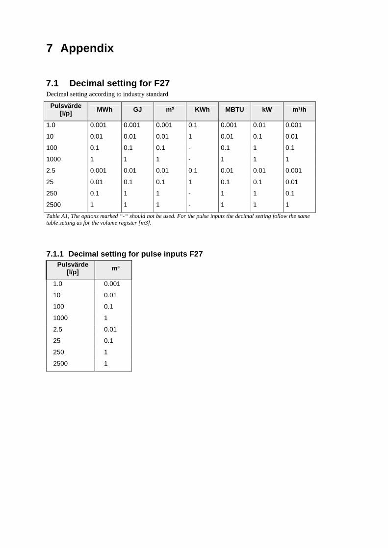
7.1 Decimal setting for F27 Decimal setting according to industry standard
Pulsvärde [l/p] MWh GJ m³ KWh MBTU kW m³/h
1.0 0.001 0.001 0.001 0.1 0.001 0.01 0.001
10 0.01 0.01 0.01 1 0.01 0.1 0.01
100 0.1 0.1 0.1 - 0.1 1 0.1
1000 1 1 1 - 1 1 1
2.5 0.001 0.01 0.01 0.1 0.01 0.01 0.001
25 0.01 0.1 0.1 1 0.1 0.1 0.01
250 0.1 1 1 - 1 1 0.1
2500 1 1 1 - 1 1 1
Table A1, The options marked “-“ should not be used. For the pulse inputs the decimal setting follow the same table setting as for the volume register [m3].
7.1.1 Decimal setting for pulse inputs F27 Pulsvärde
[l/p] m³
1.0 0.001
10 0.01
100 0.1
1000 1
2.5 0.01
25 0.1
250 1
2500 1

30
7.2 Articlenumber F27
7.2.1 F27 Threaded F27 ABCDEFGHIJ KLM A 1 Pt100 2-wire measurement, flow sensor in low (L) temp. A 2 Pt100 2-wire measurement, flow sensor in high (H) temp. B 1 Battery supply (3.6V – 16Ah) B 3 Mains supplied 230V (with backup battery 1.0 Ah) C 1 Pulse weight 2.5 [l/p] at qp= 3.5/6.0 [m³/h] C 5 Pulse weight 1 [l/p] at qp= 0.6 / 1.5 / 2.5 [m³/h] C 6 Pulse weight 10 [l/p] at qp= 10.0 [m³/h] D 0 kWh [kW m³ m³/h] D 1 MWh [kW m³ m³/h] D 2 GJ [kW m³ m³/h] D 3 MBTU [kW m³ m³/h] D 4 MBTU [kUSG kW USG/m] E - Standard order E S Special, extra ordering information enclosed with order.
Example customer information F H Pulse output, STANDARD. Jumpers for pulse inputs 1000[l/p]. G 1 No backlight (STANDARD) G 0 Backlight (option, ONLY in F27 mains supplied) H 0 qp= 0.6 [m³/h], 110[mm], G3/4” PN16 C5 1 l/p H 1 qp= 1.5 [m³/h], 110[mm], G3/4” PN16 C5 1 l/p H 2 qp= 0.6 [m³/h], 130[mm], G1” PN16 C5 1 l/p H 3 qp= 1.5 [m³/h], 130[mm], G1” PN16 C5 1 l/p H 4 qp= 2.5 [m³/h], 130[mm], G1” PN16 C5 1 l/p H 5 qp= 3.5 [m³/h], 260[mm], G1 1/4” PN16 C1 2.5 l/p H 6 qp= 6.0 [m³/h], 260[mm], G1 1/4” PN16 C1 2.5 l/p H 7 qp=10.0 [m³/h], 300[mm], G2” PN16 C6 10 l/p H 8 qp= 1.0 [m³/h], 130[mm], G1” PN16 C5 1 l/p I - No temperature sensor eqipped with F27 I 1 TDA26 temperature sensor, 2m silicone (ONLY qp=0.6 – qp=2.5 can
a TDA26 be mounted directly in the flow sensor) I 3 TL045, 2m silicone I S Special temperature sensors, specified separately on order J 1 Standard mounting KLM #00 Country code
Only TDA26 temperature sensors with a cut in the nut may be used in the flow part.
TDA26 without a cut in the nut will leak.
F27 threaded flow parts

31
F27 Flanged
F27 ABCDEFGHIJ KLM A 1 Pt100 2-wire measurement, flow sensor in low (L) temp. A 2 Pt100 2-wire measurement, flow sensor in high (H) temp. B 1 Battery supplied (3.6 – 16Ah) B 3 Mains supplied 230V (with backup battery 1.0 Ah) C 1 Pulse weight 2.5 [l/p] endast qp=3.5/6 [m³/h] C 2 Pulse weight 25 [l/p] endast qp=40/60 [m³/h] C 6 Pulse weight 10 [l/p] endast qp=10/15/25 [m³/h] D 0 KWh D 1 MWh D 2 GJ D 3 MBTU D 4 MBTU [kUSG kW USG/m] E - Standard order E S Special, extra information enclosed with order.
Example customer information F H Pulsingångar, STANDARD. Bygling för pulsingångar, 1000[l/p]. G 1 No backlight (STANDARD) G 0 Backlight (option, ONLY in F27 mains supplied) H A qp= 3.5 [m³/h], 260[mm], DN25, flange PN25 C1 2.5 l/p H B qp= 6.0 [m³/h], 260[mm], DN25, flange PN25 C1 2.5 l/p H C qp=10.0 [m³/h], 300[mm], DN40, flange PN25 C6 10 l/p H D qp=15.0 [m³/h], 270[mm], DN50, flange PN25 C6 10 l/p H E qp=25.0 [m³/h], 300[mm], DN65, flange PN25 C6 10 l/p H F qp=40.0 [m³/h], 300[mm], DN80, flange PN25 C2 25 l/p H G qp=60.0 [m³/h], 300[mm], DN100, flange PN16 C2 25 l/p I - No temperature sensor equipped with F27 I 3 TL045, 2m silicone sensor I S Special temperature sensors, specified separately on order J 1 Standard mounting KLM #00 Country code
F27 flanged flow parts


Metrima AB www.metrima.se [email protected] Norra Stationsgatan 93 SE-113 64 Stockholm Phone: +46-8 23 60 30 Fax: +46-8 23 60 31
© Metrima AB
Stockholm, Sweden
Created: 2005-01-05
Author: Johan Tsung
Rev. date 2006-05-22
Rev.by: EW
Filename: F27 Manual [2-02-02E].doc
Revision no: 0.183