Embed Size (px)
Citation preview

Digital Equipment CorporationMaynard, Massachusetts
�1.76+105
24 SBB, DSSI RAID Subsystem,Deskside Expansion Unit (SW301)User’s GuideOrder Number: EK–SW301–UG. A01
This guide describes the procedures that install and operate the 24 SBB, DSSI RAIDSubsystem deskside expansion unit (SW301).

ii
April 1996
While Digital believes the information included in this publication is correct as of the date of publication, it issubject to change without notice.
Digital Equipment Corporation makes no representations that the interconnection of its products in themanner described in this document will not infringe existing or future patent rights, nor do the descriptionscontained in this document imply the granting of licenses to make, use, or sell equipment or software inaccordance with the description.
__________________________ NOTE __________________________
This equipment has been tested and found to comply with the limits for a ClassA digital device, pursuant to Part 15 of the FCC rules. These limits aredesigned to provide reasonable protection against harmful interference whenthe equipment is operated in a commercial environment. This equipmentgenerates, uses, and can radiate radio frequency energy and, if not installed andused in accordance with the instructions, may cause harmful interference toradio communications.
Any changes or modifications made to this equipment may void the usersauthority to operate this equipment. Operation of this equipment in aresidential area may cause interference in which case the user at his ownexpense, will be required to take whatever measures may be required to correctthe interference.
___________________________________________________________
© Digital Equipment Corporation, 1996.All Rights Reserved.Printed in the United States of America.
DSSI, HS1CP, StorageWorks, and the DIGITAL logo are trademarks of Digital Equipment Corporation.

iii
Table of Contents
PREFACE
1 INTRODUCING THE DSSI RAID SUBSYSTEM
1.1 PRODUCT OVERVIEW .................................................................................................................................31.2 DSSI RAID SUBSYSTEM MAJOR COMPONENTS..........................................................................................5
1.2.1 AC Power Entry Controllers...............................................................................................................61.2.2 Power Supply SBBs............................................................................................................................71.2.3 Standard (4+1) Power Configuration..................................................................................................71.2.4 Optional (4+4) Power Configuration ..................................................................................................8
1.3 ENCLOSURE ERROR DETECTION AND REPORTING........................................................................................91.3.1 Fault Bus ...........................................................................................................................................91.3.2 Environmental Monitor Unit (EMU)..................................................................................................9
1.4 DSSI RAID SUBSYSTEM COOLING...........................................................................................................101.5 HS1CP ARRAY CONTROLLERS.................................................................................................................111.6 CONNECTING THE DSSI CABLES ..............................................................................................................121.7 SCSI BUSES............................................................................................................................................141.8 STORAGE DEVICE SBBS...........................................................................................................................15
1.8.1 CD-ROM Drives..............................................................................................................................161.8.2 Disk Drives......................................................................................................................................161.8.3 Optical Disk Drives..........................................................................................................................171.8.4 Solid State Disks..............................................................................................................................171.8.5 Cartridge Tape Drives......................................................................................................................18
2 CONFIGURING THE DSSI RAID SUBSYSTEM
2.1 POWER CONFIGURATIONS........................................................................................................................202.2 POWER DISTRIBUTION..............................................................................................................................20
2.2.1 Power Bus A....................................................................................................................................212.2.2 Power Bus B....................................................................................................................................22
2.3 SCSI BUS CONFIGURATIONS....................................................................................................................232.4 HS ARRAY CONTROLLER CONFIGURATIONS.............................................................................................232.5 INSTALLATION SEQUENCE........................................................................................................................24
3 ENCLOSURE ERROR ANALYSIS AND FAULT ISOLATION
3.1 DSSI RAID SUBSYSTEM ENCLOSURE FAULT NOTIFICATION .....................................................................253.2 ERROR REPORTING..................................................................................................................................263.3 CONTROLLER ERROR CONDITIONS ...........................................................................................................293.4 STORAGE DEVICE FAULT NOTIFICATION ...................................................................................................303.5 POWER SUPPLY FAULT NOTIFICATION.......................................................................................................313.6 DUAL SPEED BLOWERS............................................................................................................................32
4 REPLACING COMPONENTS
4.1 REPLACING A CONTROLLER OR A CACHE MODULE ....................................................................................354.2 REPLACING AN SBB STORAGE DEVICE......................................................................................................35
4.2.1 Before You Replace a Storage SBB..................................................................................................364.2.2 SBB Replacement............................................................................................................................36
4.3 REPLACING DSSI RAID SUBSYSTEM BLOWERS........................................................................................394.4 REPLACING A POWER SUPPLY SBB ...........................................................................................................40

iv
4.5 REPLACING AN EMU............................................................................................................................... 414.6 REPLACING A POWER ENTRY CONTROLLER.............................................................................................. 42
GLOSSARY
INDEX
FIGURES
Figure 1-1 DSSI RAID Subsystem................................................................................................................ 2Figure 1-2 DSSI RAID Subsystem Major Components.................................................................................. 5Figure 1-3 Typical Shelf Power Supply SBB................................................................................................. 7Figure 1-4 Dual Speed Blowers................................................................................................................... 10Figure 1-5 Typical DSSI Tri-Link Connector.............................................................................................. 12Figure 1-6 DSSI SCSI Buses....................................................................................................................... 14Figure 1-7 Typical 3.5-Inch and 5.25-inch SBBs ........................................................................................ 15Figure 2-1 Standard (4+1) DSSI Power Configuration ................................................................................ 21Figure 2-2 Redundant (4+4) DSSI Power Configuration............................................................................. 22Figure 2-3 DSSI RAID Subsystem SCSI Buses........................................................................................... 23Figure 2-4 HS1CP Controller and SBB Installation Sequence..................................................................... 24Figure 3-1 DSSI RAID Subsystem Status LEDs.......................................................................................... 25Figure 3-2 EMU Front Panel....................................................................................................................... 26Figure 3-3 EMU LED Indicators................................................................................................................. 27Figure 3-4 HS1CP OCP.............................................................................................................................. 29Figure 3-5 Typical 3.5-Inch and 5.25-Inch SBBs ........................................................................................ 30Figure 3-6 3.5 Inch Power Supply SBB....................................................................................................... 31Figure 3-7 Dual Speed Blowers Locations................................................................................................... 33Figure 4-1 Removing a Storage Device SBB............................................................................................... 38Figure 4-2 Dual Speed Blower Replacement............................................................................................... 39Figure 4-3 Removing a Power Supply SBB................................................................................................. 40Figure 4-4 Replacing an EMU .................................................................................................................... 41Figure 4-5 Replacing a Power Entry Controller........................................................................................... 42
TABLES
Table 1-1 DSSI RAID Subsystem Components............................................................................................. 3Table 1-2 HS1CP Controller....................................................................................................................... 11Table 1-3 DSSI Subsystem Compatible Cables............................................................................................ 13Table 2-1 DSSI RAID Subsystem Components........................................................................................... 19Table 2-2 DSSI Power Configurations........................................................................................................ 20Table 3-1 DSSI RAID Subsystem Enclosure Status..................................................................................... 26Table 3-2 EMU DSSI Status Indications..................................................................................................... 28Table 3-3 DSSI Power Supply Status LEDs................................................................................................. 31Table 4-1 Controller Response to SBB Replacement................................................................................... 36

v
Preface
The StorageWorks Solutions, 24 SBB, DSSI (Digital standard system interconnect) RAID (redundant array ofindependent disks) Subsystem, Deskside Expansion Unit (DSSI) User's Guide describes the purpose, function,operation, and use of the DSSI RAID subsystem and the associated power entry controllers, power supplies,environmental monitor units (EMUs), HS1CP SCSI bus controllers, and StorageWorks building blocks(SBBs). This guide, the StorageWorks Solutions Products Catalog, the StorageWorks Solutions 8-Bit I/OModule, and the StorageWorks Solutions 16-Bit I/O Module comprise the StorageWorks Solutionsdocumentation set.
Intended Audience
This publication is for use by customers and Digital™ employees responsible for configuring, installing, andmaintaining the StorageWorks subsystem and its components.
Documentation Conventions
The following conventions are used in this manual:
boldface type Boldface type indicates the first instance of terms being defined in text, in the glossary,or both.
italic type Italic type indicates emphasis and complete manual titles. In the glossary, italic typealso is used to indicate cross–references.
Structure
This manual is organized as follows:
Chapter 1 Describes the DSSI RAID subsystem including physical characteristics, layout,specifications, components, StorageWorks SBBs and general information.
Chapter 2 Describes the how to configure the DSSI RAID subsystem power and SCSI buses.
Chapter 3 Describes how the DSSI RAID subsystem and the device status are monitored andreported. This chapter includes recommended corrective action for fault conditions.
Chapter 4 Describes the procedures replacing SBB power supplies, SBB storage devices,environmental monitor unit (EMU), controllers, blowers, and power entry controllers.
Glossary
Index

Introducing the DSSI RAID Subsystem 1
1Introducing the DSSI RAID Subsystem
This chapter describes the DSSI RAID subsystem deskside expansion unit shown in Figure 1-1. Thisdescription includes features, unit layout, Small Computer System Interface (SCSI) bus, power, cabling,StorageWorks building blocks (SBBs), and general user information. A label inside the cabinet front dooridentifies a wide compatible subsystem.
__________________________ Note __________________________
The DSSI RAID subsystem requires at least one HS1CP array controller forproper operation. This user’s guide discusses only controller replacementprocedures. For detailed descriptions of the individual controllers, use,configuration, operation, storage device compatibility, SCSI bus, anddiagnostics, refer to the specific controller documentation.
___________________________________________________________
Figure 1-1 DSSI RAID Subsystem
CXO-4268A-MC

2 Introducing the DSSI RAID Subsystem
1.1 Product Overview
The DSSI RAID subsystem is a member of the Digital StorageWorks family of modular enclosures thatcontain StorageWorks storage devices, power supplies, and controllers. Table 1-1 shows DSSI RAIDsubsystem components.
Table 1-1 DSSI RAID Subsystem Components
Power Configurations
Component Order No.Standard
(4+1)Option(4+4)
Blower (dual speed) BA35X–MD 8 8Environmental monitor unit (EMU) BA35X–EA 1 2Power controller BA35X–HE 2 2Shelf power supply (150W) BA35X–HD 5 8HS1CP array controller 2HS1CP cache memory module 2
Customer Specified OptionsStorage devices:
(Based on 6 SCSI buses;minimum of one device per bus)
SBB Size3.5-inch5.25-inch
Minimum60
Maximum248
DSSI cable to host See Chart
__________________________ CAUTION ______________________
The specific storage devices installed must be compatible with the HS1CPcontroller and with each other.
___________________________________________________________
The following are the major features of the DSSI RAID subsystem:
• All major components, except the cache memory modules, can be replaced using either the hot swap or warmswap methods (see Chapter 4 for detailed information).
• Extensive fault monitoring and reporting capability includes the following:
− Incorrect voltage
− Shelf blower failure
− Power supply failure
− Operating temperature
− Storage device removal
− Device operational status
− Storage device installation
• Automatic initiation of system protection actions
• Six, single-ended, 8-bit/16-bit INTERNAL SCSI buses
• SCSI buses are configured and terminated
• No SCSI cables required to connect controllers to devices

Introducing the DSSI RAID Subsystem 3
1.2 DSSI RAID Subsystem Major Components
The major components of the DSSI RAID subsystem are shown in Figure 1-2.
• Power controller with a power ON/OFF switch, noise filters, surge suppression, and electromagneticinterference (EMI ) filters.
• SBB power supplies that convert the ac input to +12 V dc and +5 V dc.
__________________________ CAUTION ______________________
A minimum of four operational SBB power supplies is required for operation ofthe following DSSI RAID subsystem components: 2 − EMUs, 2 – HS1CPControllers, 2 – Cache Memories, 24 – 3.5-inch SBBs
___________________________________________________________
Figure 1-2 DSSI RAID Subsystem Major Components
CXO-4305A-MC
PowerSupply SBB
Storage Device SBB
AC PowerEntry Controller A
AC PowerEntry Comtroller B
HS ArrayController
Dual-SpeedBlower
Power A
Power B
EnvironmentalMonitor Unit
Single - EndedWIDE SCSI Device
Compatible

4 Introducing the DSSI RAID Subsystem
When there are less than four operational power supplies, the RAID subsystem will cease operating to preserveand protect the data.
See Chapter 2 for a detailed description of the power configurations and power cord connections. Described inthe following sections are three possible power configurations for each DSSI RAID subsystem:
• Standard—four power supply SBBs, plus one redundant power supply SBB (4+1)
• Option—four power supply SBBs, plus four redundant power supply SBBs (4+4); and two power controllers
1.2.1 AC Power Entry Controllers
The ac input power is routed from the wall outlet to a power entry controller. These power controllers useeither of the following input voltages:
• 100–120 V ac, 60 Hz, single-phase, 12A
• 220–240 V ac, 50 Hz, single-phase, 6A
The two ac power entry controllers provide the system ON/OFF switch, ac power to all power supply SBBs.

Introducing the DSSI RAID Subsystem 5
1.2.2 Power Supply SBBs
__________________________ CAUTION ______________________
The DSSI RAID subsystem requires power supply SBBs rated for at least150 W. Lower rated supplies, such as the 131 W BA35X–HA, cannot be used.
___________________________________________________________
The power supply SBB shown in Figure 1-3 converts the ac voltage from the power controller to +5 V dc and+12 V dc and distributes these voltages throughout the RAID subsystem. The maximum capacity of the DSSIRAID subsystem is eight power supplies. A minimum of five operable power supply SBBs is required for 4+1standard system operation.
The 4+1 configuration provides five suppies connected to power bus A by the black power cords. As long asany four of these supplies are operational, the RAID subsystem is operational. The failure of a second supplyplaces the RAID subsystem controller in a reset state. This precludes further data processing and prevents thecorruption or loss of the stored data.
With the 4+4 full redundant power option, the RAID subsystem can survive multiple power supply faults. Tofully realize the benefits of the 4+4 configuration, connect the power controllers to different ac distributioncircuits (legs).
The four RAID subsystem power supply SBBs on the left end of the shelf are connected to power controller A.The four RAID subsystem power supply SBBs on the right end of the shelf are connected to power controllerB.
Figure 1-3 Typical Shelf Power Supply SBB
CXO-4787A-MC
Power BusStatus LED(Green)
Power SupplyStatus LED(Green)

6 Introducing the DSSI RAID Subsystem
1.2.3 Standard (4+1) Power Configuration
__________________________ Note __________________________
The black power cord at the upper right corner of the DSSI RAID subsystem isused only for the standard (4+1) configuration. It is not used for either the basicor redundant (4+4) configurations.
___________________________________________________________
This standard power configuration is recommended by Digital. If a power supply SBB fails you would be ableto replace it before a second power supply SBB fails. The standard power configuration has the followingcomponents:
5 — power supply SBBs
2 — ac power controllers
Any one of the following error conditions will cause the DSSI RAID subsystem to cease operation and maycause loss or corruption of data:
• Failure of two power supply SBBs
• Power controller failure
1.2.4 Optional (4+4) Power Configuration
Digital recommends this power configuration for complete data protection. The redundant powerconfiguration provides complete redundancy for all power system components. Loss or corruption of data mayoccur only when any one of the following multiple error conditions occurs before you take corrective action:
• Failure of five power supply SBBs
• Failure of both power controllers
Two separate ac power sources and two ac power controllers are required for full redundant power operation.
The first ac source provides power to controller A, which distributes the ac power through the five black powercords at the left end of the device shelves.
The second ac source provides power to controller B, which distributes the ac power through the four graypower cords to shelf power SBBs at the right end of the device shelves.
In all configurations, the four power supply SBBs on the left end of the shelf are connected to this bus with theblack power cords.
For the standard configuration, a power supply SBB is installed at the right end of the top device shelf and theblack power bus A cord is connected.

Introducing the DSSI RAID Subsystem 7
1.3 Enclosure Error Detection and Reporting
The DSSI RAID subsystem error detection and reporting function has two major elements—the fault bus andEMU. For a detailed discussion about error detection, fault reporting, and correction see Chapter 3.
1.3.1 Fault Bus
The RAID subsystem fault bus monitors the subsystem enclosure operation and reports fault conditions to theHS1CP array controller and the EMU. The controller and EMU then report the error condition to the user.The fault bus monitors the following conditions:
• Blower failure (SHELF_OK)
• Storage device removal (SWAP_L)
• Power supply failure (SHELF_OK)
• Storage device installation (SWAP_L)
• SBB failure (FAULT_CLK, FAULT_DATA)
The fault bus consists of three subsystem backplane signals routed to the port connectors on the arraycontrollers:
• Shelf Status SignalThe SHELF_OK status signal indicates the state of the RAID subsystem power (ac and dc) and bloweroperation.
• SBB Swap SignalThe SWAP_L signal is asserted whenever an SBB is either removed from or inserted in the RAID subsystem.
• SBB Fault SignalsThe SBB amber light emitting diode (LED) displays either the storage device address or indicates a device fault.This device fault LED is controlled by the fault clock (FAULT_CLK) and the fault data (FAULT_DATA)control signals.
For a detailed technical description of the fault bus, refer to the High Availability Storage subsystem Fault BusEngineering Specification. The controller uses the fault bus signals in the manner described in the controllerspecifications.
1.3.2 Environmental Monitor Unit (EMU)
The EMU provides protection against catastrophic DSSI RAID subsystem faults. Together the EMU and thecontroller warn the user of existing or impending failures using one or more of the following error reportingsystems:
• SBB LEDs.
• EMU LEDs.
• A user-enabled EMU audible alarm
• Error messages on the host interface.
• Error messages on the maintenance terminal.
• Controller operator control panel (OCP) LEDs.
• In some instances, the EMU automatically initiates corrective actions.
8 Introducing the DSSI RAID Subsystem
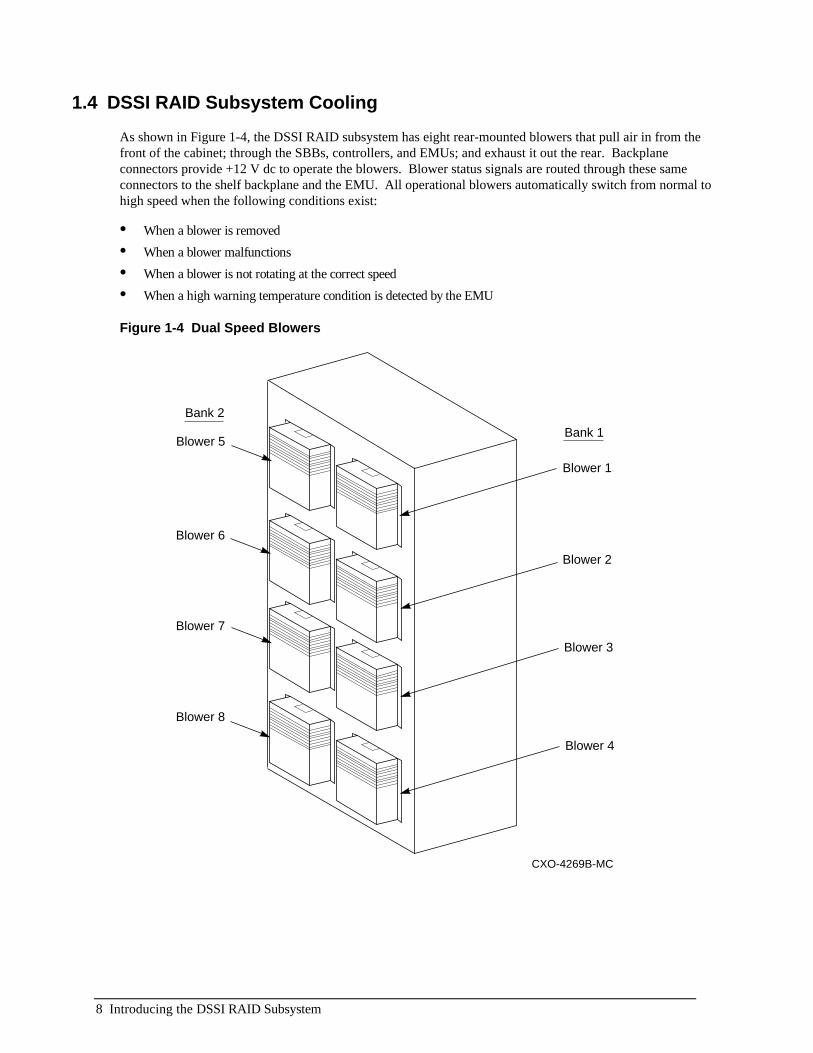
1.4 DSSI RAID Subsystem Cooling
As shown in Figure 1-4, the DSSI RAID subsystem has eight rear-mounted blowers that pull air in from thefront of the cabinet; through the SBBs, controllers, and EMUs; and exhaust it out the rear. Backplaneconnectors provide +12 V dc to operate the blowers. Blower status signals are routed through these sameconnectors to the shelf backplane and the EMU. All operational blowers automatically switch from normal tohigh speed when the following conditions exist:
• When a blower is removed
• When a blower malfunctions
• When a blower is not rotating at the correct speed
• When a high warning temperature condition is detected by the EMU
Figure 1-4 Dual Speed Blowers
CXO-4269B-MC
Blower 5
Blower 6
Blower 7
Blower 8
Blower 1
Blower 2
Blower 3
Blower 4
Bank 2
Bank 1

Introducing the DSSI RAID Subsystem 9
1.5 HS1CP Array Controllers
The HS1CP array controllers provide a means of connecting the Digital host system to the RAID subsystem.
Install two HS1CP controllers with cache memories to provide complete controller redundancy as described inStorageWorks Array Controllers HS Family of Array Controllers User's Guide. The controller documentationdescribes:
• Configuring the controller
• Connecting a maintenance terminal to set initial controller parameters
• Determining the proper method for replacing SBBs (hot swap or warm swap)
The controller firmware revision level determines the devices supported by each controller. See the controllerrelease-specific StorageWorks Array Controller Operating Firmware Release Notes for a list of supportedstorage devices.
The DSSI RAID subsystem supports the HS1CP controller (see Table 1-2). This table shows the number ofoutput SCSI buses (Ports) and the compatible cache memories (Cache Memory).
__________________________ CAUTION ______________________
To replace a write-back cache module you must use the procedures inStorageWorks Array Controllers HS Family of Array Controllers User's Guide.
___________________________________________________________
Table 1-2 HS1CP Controller
Model Input Ports Cache MemoryHS1CP DSSI 6 Any of the following caches may be installed:
16-MB read 32-MB read16-MB write-back 32-MB write-back

10 Introducing the DSSI RAID Subsystem
1.6 Connecting the DSSI Cables
__________________________ CAUTION ______________________
All DSSI buses must be terminated whenever power is applied. Disconnecting aDSSI bus cable when the power is applied removes termination from the bus andcan generate erroneous signals and cause the bus to hang. To avoid thiscondition never connect or disconnect a DSSI cable with power applied to eitherthe host or the controller.
___________________________________________________________
Complete the following procedure to connect the DSSI cable to the HS1CP controller (see Figure 1-5):1. Install the connector guide over the 68-pin DSSI controller connector.2. Connect the DSSI cable as required.3. Install the tri-link connector on the 68-pin DSSI controller connector.
Figure 1-5 Typical DSSI Tri-Link Connector
1 2 3 4 5 6
CXO-5198A-MC
CONTROLLER
HOST PORTCONNECTORWITH MATINGGUIDE
TRILINKADAPTER
HOST PORT CABLE(TO OTHER UNITS)
HOST PORTCABLE (FROM HOST)
CAPTIVE SCREW(2X)
The DSSI bus cable you use is dependent upon the following:
• The computer host.
• The adapter type.

Introducing the DSSI RAID Subsystem 11
See Table 1-3 to determine the compatible DSSI cable series for connecting the pedestal to a host adapter. Fordetailed information about these cables see the StorageWorks Solutions HS1CP Array Controller ReleaseNotes, order number EK–HS1CP–RN.
Table 1-3 DSSI Subsystem Compatible Cables
If the host and adapterare…
the cable to use is …
Alpha Server 2000™KFESA
BC29R
CXO-5224A-MC
Alpha Server 2000™KFESBKFPSA
BC29S
CXO-5192A-MC
Alpha Server 2100™KFESA
BC29R
CXO-5224A-MC
Alpha Server 2100™KFESBKFPSA
BC29S
CXO-5192A-MC

12 Introducing the DSSI RAID Subsystem
1.7 SCSI Buses
The factory-configured six 8-bit SCSI buses and the associated ports and device addresses are shown inFigure 1-6. The DSSI RAID subsystem enclosure supports 16-bit storage devices operating in -bit mode. Theconfiguration rules for these single-ended SCSI buses are as follows:
• May install all current level 8-bit -VW devices.
• Termination boards are installed on the top, rear of the backplane.
• All devices and ports in the same column are on the same SCSI bus or port.
• Device addresses 4 and 5 are only used if the SBB has a device address switch.
• All the devices in the same horizontal row (device shelf) have the same device address.
• Device addresses are determined by the backplane connector into which the device is inserted.
• Each terminator board terminates two buses (that is, Bus 1–Bus 2, Bus 3–Bus 4, and Bus 5–Bus 6).
Figure 1-6 DSSI SCSI Buses
CXO-4785A-MC
Port/Bus 2
Port/Bus 4
Port/Bus 6
Port/Bus 1
ID0
ID6
ID7
ID1
ID2
ID3
Port/Bus 3
Port/Bus 5
DeviceAddress 3
DeviceAddress 2
DeviceAddress 1
Typ
ical
Bac
kpla
ne C
onne
ctio
n
DeviceAddress 0
DeviceAddress 6
DeviceAddress 7

Introducing the DSSI RAID Subsystem 13
1.8 Storage Device SBBs
The DSSI RAID subsystem accommodates the 3.5-inch and 5.25-inch storage device SBBs(see Figure 1-7).
• 24 — 3.5-inch SBBs, each occupying one slot OR
• 8 — 5.25-inch SBBs, each occupying three slots OR
• a combination of both
The 8-bit SCSI device addresses can be assigned in the following ways:
• By the backplane connector
• With the SCSI device address switch mounted on the rear of the 5.25-inch SBBs and some 3.5-inch SBBs
The 16-bit SCSI devices are assigned only the lower 8-bits of the address.
For detailed information about SCSI device addressing see either StorageWorks Solutions Shelf and SBB User'sGuide or the StorageWorks Solutions SBB User's Guide.
To determine the SBBs that can be used in a DSSI RAID subsystem—refer to the HS array controller (HS1CP)software product descriptions (SPDs).
See the StorageWorks Solutions Product Catalog for a list of available SBBs.
Figure 1-7 Typical 3.5-Inch and 5.25-inch SBBs
CXO-5254A-MC
DeviceActivity(Green)
DeviceFault(Amber)
DeviceActivity(Green)
DeviceFault(Amber)

14 Introducing the DSSI RAID Subsystem
1.8.1 CD-ROM DrivesYou can install the following CE Mark certified StorageWorks CD-ROM drives:
CXO-5167A-MC
0.600 GB Quad Speed (4X) High Performance CD-ROMLower Half-Height.................................................................... RRD45-VA
0.600 GB Quad Speed (4X) High Performance CD-ROMUpper Half-Height.................................................................... RRD45-VU
NOTEYou can install, but not order, the following compatible devices.
0.600 GB Dual Speed (2X) High Performance CD-ROMLower Half-Height.................................................................... RRD43-VA
0.600 GB Dual Speed (2X) High Performance CD-ROMUpper Half-Height.................................................................... RRD43-VU
0.600 GB Dual Speed (2X) High Performance CD-ROMLower Half-Height.................................................................... RRD44-VA
0.600 GB Quad Speed (4X) High Performance CD-ROMUpper Half-Height.................................................................... RRD44-VU
1.8.2 Disk DrivesYou can install the following CE–Mark certified disks drives, (fixed, removable):
CXO-4562A-MC
CAUTIONInstalling a 7200 RPM disk drive may require additional cooling.
1.05 GB Fixed Disk Drive—5400 RPM............................................ RZ26L–VW
1.05 GB Fixed Disk Drive—5400 RPM............................................ RZ26N–VA
1.05 GB Fixed Disk Drive—5400 RPM............................................ RZ26N–VW
2.1 GB Fixed Disk Drive—5400 RPM.............................................. RZ28M–VA
2.1 GB Fixed Disk Drive—5400 RPM.............................................. RZ28M–VW
2.1 GB Fixed Disk Drive—7200 RPM.............................................. RZ28D–VA
2.1 GB Fixed Disk Drive—7200 RPM.............................................. RZ28D–VW
4.3 GB Fixed Disk Drive—7200 RPM.............................................. RZ29B–VA
4.3 GB Fixed Disk Drive—7200 RPM.............................................. RZ29B–VW
NOTEYou can install, but not order, the following compatible devices.
1.05 GB Fixed Disk Drive—5400 RPM............................................. RZ26L–VA
2.1 GB Fixed Disk Drive—5400 RPM............................................... RZ28–VA
2.1 GB Fixed Disk Drive—5400 RPM............................................... RZ28–VW
2.1 GB Fixed Disk Drive—5400 RPM............................................... RZ28B–VA

Introducing the DSSI RAID Subsystem 15
1.8.3 Optical Disk DrivesYou can install the following CE Mark certified StorageWorks optical disk drive:
CXO-5169A-MC
1.3 GB Removable Optical Disk Drive, Full-Height.......................... RWZ52–VA
1.8.4 Solid State DisksYou can install the following CE–Mark certified StorageWorks solid state disks (SSDs):
CXO-5168A-MC
134 Mb Solid State Disk, Full-Height .............................................. EZ31–VW
268 Mb Solid State Disk, Full-Height .............................................. EZ32–VW
CXO-4800A-MC
0.475 GB Solid State Disk, Full-Height........................................... EZ64–VA
0.950 GB Solid State Disk, Full-Height........................................... EZ69–VA
NOTEYou can install, but not order, the following compatible devices.
0.107 GB Solid State Disk with Integrated Data Retention, Full-Height EZ51R–VA
0.428 GB Solid State Disk with Integrated Data Retention, Full-Height EZ54R–VA
0.856 GB Solid State Disk with Integrated Data Retention, Full-Height EZ58R–VA

16 Introducing the DSSI RAID Subsystem
1.8.5 Cartridge Tape DrivesYou can install the following CE–Mark certified StorageWorks cartridge tape drives (DAT, DLT)
CXO-5168A-MC
8 GB 4 mm DAT Cartridge Tape Drive............................................ TLZ07–VA
NOTEYou can install, but not order, the following compatible devices.
4 GB 4 mm DAT Cartridge Tape Drive............................................ TLZ06–VA
CXO-5169A-MC
20 GB DLT Cartridge Tape Drive—Full Height............................... TZ87–VA
20 GB DLT Cartridge Tape Drive—Full Height............................... TZ87N–VA
32 GB 4 mm DAT 4 Cartridge Tape Drive Loader—Full Height...... TLZ7L–VA
NOTEYou can install, but not order, the following compatible devices.
16 GB 4 mm DAT 4 Cartridge Tape Drive Loade—Full Height r...... TLZ6L–VA

Configuring the DSSI RAID Subsystem 17
2Configuring the DSSI RAID Subsystem
This chapter describes the basic rules for configuring a DSSI RAID subsystem. Table 2-1 lists the componentsrequired for an operational DSSI RAID subsystem. The first part of the table lists the components suppliedwith shelf and the upgrade kit. The second part of this table lists the components required to make the systemoperational, the configure-to-order (CTO) components.
Table 2-1 DSSI RAID Subsystem Components
DSSI Series Standard Components QuantityDual speed blowers 8Environmental monitor unit (EMU) 1HS1CP controller with cache memory 2Power entry controller 2Power supply SBBs 5ac power cord—black 5ac power cord—gray 4Power entry controller ac power cords 2
Customer Specified Components Min Max3.5-inch storage SBBs 6 245.25-inch storage SBBs 0 8Environmental monitor unit (EMU) 1 2DSSI cables: controller to host 1 4

18 Configuring the DSSI RAID Subsystem
2.1 Power Configurations
The DSSI RAID subsystem is configured for dual ac power which includes two ac power controllers.
This is the optimum ac power configuration and is recommended for use with the 4+4 redundant shelf powerconfiguration. These configurations provide the maximum protection for your data.
Table 2-2 lists the RAID subsystem power configurations. To easily identify the ac power controller providingpower to the power bus, different colored (black and gray) power cords are used:
• Black power cords are connected to power entry controller A.
• Gray power cords are connected to power entry controller B.
Table 2-2 DSSI Power Configurations
Power CordsBus Type Power Supply Locations Bus A
(Black)Bus B(Gray)
Power Supply Bus A (Single Power Controller)Standard (4+1) Single SBB power supply in Slot A on each shelf
Single SBB power supply in Slot B, top shelf5 0
Power Supply Buses A and B (Dual Power Controllers)Optional (4+4) SBB power supplies in Slots A and B on each
shelf4 4
2.2 Power Distribution
The ac power is distributed to the DSSI power supply SBBs over two separate ac power buses—power bus Aand power bus B. Each bus has its own ac input power source, power controller, and power cords.
Configuring the DSSI RAID Subsystem 19
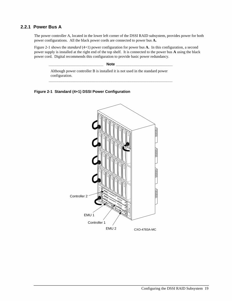
2.2.1 Power Bus A
The power controller A, located in the lower left corner of the DSSI RAID subsystem, provides power for bothpower configurations. All the black power cords are connected to power bus A.
Figure 2-1 shows the standard (4+1) power configuration for power bus A. In this configuration, a secondpower supply is installed at the right end of the top shelf. It is connected to the power bus A using the blackpower cord. Digital recommends this configuration to provide basic power redundancy.
__________________________ Note ___________________________
Although power controller B is installed it is not used in the standard powerconfiguration.
___________________________________________________________
Figure 2-1 Standard (4+1) DSSI Power Configuration
CXO-4783A-MC
Controller 2
Controller 1
EMU 1
EMU 2

20 Configuring the DSSI RAID Subsystem
2.2.2 Power Bus B
Power Bus B is only used in the optional (4+4) power configuration (see Figure 2-2). Power controller Bprovides power to four power supply SBBs at the right end of the RAID subsystem (gray power cords).
Figure 2-2 Redundant (4+4) DSSI Power Configuration
CXO-4782A-MC
Controller 2
Controller 1
EMU 1
EMU 2

Configuring the DSSI RAID Subsystem 21
2.3 SCSI Bus Configurations
The six single-ended, SCSI buses are oriented vertically on the RAID subsystem backplane. Each busconnects a HS1CP controller to one device on each device shelf for a total of four devices per SCSI bus (deviceaddresses 0 through 3). The two HS1CP array controllers, SCSI initiator device addresses are preset by slotlocation to device addresses 6 and 7 (see Figure 2-3).
Figure 2-3 DSSI RAID Subsystem SCSI Buses
CXO-4785A-MC
Port/Bus 2
Port/Bus 4
Port/Bus 6
Port/Bus 1
ID0
ID6
ID7
ID1
ID2
ID3
Port/Bus 3
Port/Bus 5
DeviceAddress 3
DeviceAddress 2
DeviceAddress 1
Typ
ical
Bac
kpla
ne C
onne
ctio
n
DeviceAddress 0
DeviceAddress 6
DeviceAddress 7
2.4 HS Array Controller Configurations
For information on RAID and other controller configurations, see the following publications:
• StorageWorks Array Controllers HS Family of Array Controllers User's Guide
• StorageWorks Array Controllers HS Family of Array Controllers Service Manual

22 Configuring the DSSI RAID Subsystem
2.5 Installation SequenceFor the most effective DSSI RAID subsystem operation, install the HS1CP controllers and SBBs in thefollowing sequence (see Figure 2-4):1. Install the first HS1CP controller in Device Address 7.2. Install the second HS1CP controller in Device Address 6.3. Install the first storage device SBB at the left end of the bottom shelf (Device Address 0, SCSI Bus 1).
Completely fill the bottom shelf from left to right.4. Once the bottom shelf is full, install the next SBB starting at the left end of the second shelf (Device Address 1,
SCSI Bus 1). Completely fill the second shelf from left to right.5. Once the second shelf is full, install the next SBB starting at the left end of the third shelf (Device Address 2,
SCSI Bus 1). Completely fill the third shelf from left to right.6. Once the third shelf is full, install the next SBB starting at the left end of the top shelf (Device Address 3, SCSI
Bus 1). Completely fill the third shelf from left to right.
Figure 2-4 HS1CP Controller and SBB Installation Sequence
17
11
CXO-4786A-MC
Port/Bus 2
Port/Bus 4
Port/Bus 6
Port/Bus 1
Port/Bus 3
Port/Bus 5
DeviceAddress 3
DeviceAddress 2
DeviceAddress 1
DeviceAddress 0
DeviceAddress 6
DeviceAddress 7
19 20 21 22 23 24
13 14 15 16 18
7 8 9 10 12
1 2 3 4 5 6
Controller 2
Controller 1
Error Analysis and Fault Isolation 23
3Enclosure Error Analysis and Fault Isolation
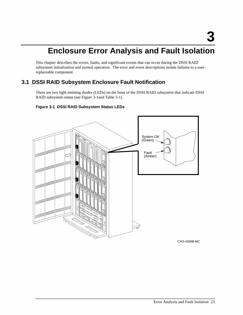
This chapter describes the errors, faults, and significant events that can occur during the DSSI RAIDsubsystem initialization and normal operation. The error and event descriptions isolate failures to a user-replaceable component.
3.1 DSSI RAID Subsystem Enclosure Fault Notification
There are two light emitting diodes (LEDs) on the front of the DSSI RAID subsystem that indicate DSSIRAID subsystem status (see Figure 3-1and Table 3-1).
Figure 3-1 DSSI RAID Subsystem Status LEDs
CXO-4309B-MC
System OK(Green)
Fault(Amber)

24 Error Analysis and Fault Isolation
Table 3-1 DSSI RAID Subsystem Enclosure Status
CXO-5190A-MC
When the SW300 LEDs are... The subsystem status is...
System OK ONFault LED OFF
System OK OFF
Fault LED ON
Is in the normanl operating state.
The subsystem does not have power applied or is in a Reset state. 1. Check that ac power is applied. 2. Check the EMU control panel LEDs to determine which FRU has failed. 3. Check the system has at least four operational power supply SBBs. 4. Check for any error messages on the terminal (if one is attached).Has a failed FRU. Check the EMU control panel LEDs todetermine which FRU has failed.
3.2 Error Reporting
DSSI RAID subsystem enclosure error conditions are displayed on the EMU front panel LEDs(see Figure 3-2).
Figure 3-2 EMU Front Panel
5 6 7 8
Blowers
Blowers
12 3 4
AudibleAlarm Switch
System OK
Temperature
Shelf Fault
CXO-4310A-MC
All DSSI RAID subsystem enclosure error conditions are processed by the EMU which performs the followingfunctions during routine operations:
• Senses shelf temperature
• Monitors the power supplies
• Monitors the power supply voltage
• Monitors and controls the cabinet blowers

Error Analysis and Fault Isolation 25
When the EMU detects one or more fault conditions, it implements the following actions:
• Enables the audible alarm
• Turns on the amber shelf fault LED
• Turns on one or more EMU panel LEDs
The front panel LEDs display DSSI RAID subsystem enclosure status information (see Figure 3-2). Any errorcondition can cause the audible alarm to sound.
__________________________ Note __________________________
The audible alarm only operates when the EMU front panel audible alarmswitch is in the up (enabled) position.
___________________________________________________________
The EMU front panel LEDs (see Figure 3-3) display the status of the DSSI RAID subsystem enclosure(SYSTEM OK), the temperature (TEMPERATURE), error conditions (SHELF FAULT), and the status of theindividual blowers and banks of blowers (BLOWERS). When the DSSI RAID subsystem enclosure isfunctioning properly, only the SYSTEM OK LED is on.
Figure 3-3 EMU LED Indicators
CXO-4788A-MC
1 2 3 4
5 6 7 8
Temerature
Blowers
Blowers
ShelfFaultSystem OK

26 Error Analysis and Fault Isolation
Table 3-2 is a summary of the basic EMU LED displays, the DSSI status, and corrective actions.
Table 3-2 EMU DSSI Status Indications
When the EMU LED display is… The DSSI status is…
CXO-4789A-MC
1 2 3 4
5 6 7 8
The RAID shelf is fully operational.
CXO-4790A-MC
1 2 3 4
5 6 7 8
The RAID subsystem temperature is above 35°C(95°F).All blowers are operating at high speed.Determine and correct the cause of this conditionas quickly as possible.
When the temperature exceeds 50°C (122°F) theEMU places the HS array controller in theRESET state. This will halt all data transfersthereby preventing the loss or corruption of data.
CXO-4791A-MC
1 2 3 4
5 6 7 8
There is a RAID subsystem power problem.
Observe the power supply LEDs to determine thedefective supply and replace it.
CXO-4792A-MC
1 2 3 4
5 6 7 8
One or more blowers are nonoperational.
In this example Blowers 1 and 7 arenonoperational and must be replaced.
CXO-4793A-MC
1 2 3 4
5 6 7 8
Either a blower is not installed or it is installedincorrectly.
In this example, the error condition is caused by aBank 1 blower.
Check Blowers 1, 2, 3, and 4 to isolate theblower causing the problem and install itproperly.

Error Analysis and Fault Isolation 27
3.3 Controller Error Conditions
The HS1CP operator control panel (OCP) (see Figure 3-4), has the following switches and indicators:
• Controller reset switch with an embedded green status LED
• Six SCSI port (bus) reset switches
• Six amber SCSI bus status LEDs
Figure 3-4 HS1CP OCP
CXO-4823A-MC
ControllerReset Switch
Port ResetSwitch(1 of 6)
Port LED(1 of 6)
The green controller reset LED indicates controller status. This LED flashes constantly once the controllerinitialization is complete and the firmware is functioning. Pressing this switch resets the controller.
The amber port LEDs are off when the bus is functioning properly. A port LED that is on or flashingindicates that a device on the bus is not functioning properly.
Pressing and holding any port reset switch will quiesce the bus and turn on the amber LED. Depending on thecontroller, you may have to quiesce a bus to replace a storage device. For further information aboutrequirements for quiescing the bus, see the StorageWorks Array Controllers HS Family of Array ControllerUser’s Guide.

28 Error Analysis and Fault Isolation
3.4 Storage Device Fault Notification
The storage device SBBs are either a 3.5-inch or a 5.25-inch form factor (see Figure 3-5). The front panelLEDs have three states (on, off, and flashing) to display the SBB status.
• The green LED is the device activity LED and is on or flashing when the SBB is active.
__________________________ Note __________________________
Removing a storage SBB when the device activity (upper) LED is on or flashingcan cause the loss or corruption of data.
___________________________________________________________
The amber LED is the device fault LED and indicates an error condition or configuration problem when it iseither on or flashing.
Figure 3-5 Typical 3.5-Inch and 5.25-Inch SBBs
CXO-5254A-MC
DeviceActivity(Green)
DeviceFault(Amber)
DeviceActivity(Green)
DeviceFault(Amber)

Error Analysis and Fault Isolation 29
3.5 Power Supply Fault Notification
Each power supply SBB has two green LEDs that display the power supply status, as shown inTable 3-3.
Table 3-3 DSSI Power Supply Status LEDs
CXO-5191A-MC
When the LED display is... The RAID subsystem power status is ...
All the power supply SBBs on the associated power bus are functioningproperly.
At least one power supply on the associated power bus hasmalfunctioned.This supply is operating properly.
Either there is no ac power to this supply or this power supply should be replaced.
Figure 3-6 3.5 Inch Power Supply SBB
CXO-4787A-MC
Power BusStatus LED(Green)
Power SupplyStatus LED(Green)

30 Error Analysis and Fault Isolation
3.6 Dual Speed Blowers
__________________________ Note __________________________The DSSI RAID subsystem uses only Model BA35X–MD, dual speed blowers.Model BA35X–MA, the single speed blower, is not an acceptable substitute andcannot be used as a replacement.
___________________________________________________________
As shown in Figure 3-7, the RAID subsystem has eight rear-mounted blowers that pull air in from the front ofthe cabinet; through the SBBs, controllers, and EMUs; and exhaust it out the rear. Backplane connectorsprovide +12 V dc to operate the blowers. Blower status signals are routed through these connectors to theshelf backplane and the EMU. All operational blowers go from normal to high speed when the followingconditions exist:
• When a blower is removed
• When a blower malfunctions
• When a blower is not rotating at the correct speed
• When a high warning temperature condition is detected by the EMU
The EMU monitors the blower status logic signals and displays error conditions and controls the bloweroperating speed.
Figure 3-7 Dual Speed Blowers Locations
CXO-4269A-MC
Blower 5
Blower 6
Blower 7
Blower 8
Blower 1
Blower 2
Blower 3
Blower 4

Replacing Components 31
4Replacing Components
This chapter describes the procedures to remove and install the following components in the DSSI RAIDsubsystem:
• Power entry controller
• SBB storage device
• Dual speed blower
• Power supply SBBs
• EMU
4.1 Replacing a Controller or a Cache ModuleReplacing the HS1CP array controllers and cache memories are complex procedures. Therefore, theseprocedures are not within the scope of this publication. The StorageWorks Array Controllers HS Family ofArray Controllers User’s Guide’s contain the complete procedures for replacing these devices.
4.2 Replacing an SBB Storage Device
Replacing an SBB involves quickly removing and replacing a storage device or power supply using eitherthe warm swap or the hot swap method depending upon the capabilities of the controller. The differencesbetween these two methods are as follows:
hot swap—A method of device replacement whereby the complete system remains on-line and activeduring device removal or insertion. The device being removed or inserted is the only device that cannotperform operations during this process.
warm swap—A method of device replacement whereby the complete system remains on-line duringdevice removal or insertion. A single SCSI bus may be halted for a brief period of time, during deviceinsertion or removal. No booting or loading of code is permitted except on the device being inserted.
The method used to replace a device must preserve the data integrity and either the controller or the operatormust determine that the swap is necessary. The SBB swap methods can be used to add a device.
The controller determines that a device is bad by trying to access the device, receiving no response from thedevice, or detecting excessive errors from the device.

32 Replacing Components
The operator decides to remove a device by examining the controller operator control panel (OCP) codes, theSBB LEDs, system messages, or system error log information.
__________________________ CAUTION ______________________
Both the hot swap and warm swap methods support removing and replacing asingle storage SBB. You must repeat the complete procedure for each SBB youare replacing.
___________________________________________________________
4.2.1 Before You Replace a Storage SBB
Whenever you replace a storage SBB, you must consider the following factors:
• Installing a different model device requires you to reconfigure the subsystem.
• You cannot replace a device that is active (the green device activity LED is flashing) without losing or corruptingdata.
• You do not need electrostatic discharge (ESD) protection, such as an ESD wrist strap, to replace an SBB.However, you can cause ESD damage by touching the SBB connector.
Always use both hands to remove or install an SBB.
4.2.2 SBB Replacement
The procedures for replacing a storage SBB accomplish the following:
• Preserve data integrity.
• Make sure that the controller performs in a predictable manner.
• Reduce the time a port and the associated devices are not available.
Removing or inserting a storage SBB generates the C_SWAP low signal. Table 4-1 describes the expectedcontroller responses.
Table 4-1 Controller Response to SBB Replacement
Action Expected Controller Response
Removing a storage device when data is not being transferredNo controller response expected.
Removing a storage device during a data transfer operationReduced operation.
Installing a storage device The controller begins to reconstruct thedata on the disk.

Replacing Components 33
In general, the procedure for replacing an SBB is the same for most controllers. However, there may besignificant operating system or firmware differences. Therefore, the following procedure is an outline. Referto the controller user documentation for the detailed procedure you should use.
Complete the following procedure to replace an SBB:1. Dismount the device.2. Quiesce the SCSI bus (port). The controller OCP LEDs display indicates the bus status and when you can
remove or insert an SBB.
__________________________ Note __________________________
You can quiesce only one port at a time.___________________________________________________________
3. You can remove or install an SBB only when the controller OCP LEDs indicate:
• There is no I/O activity on any bus.
• Removing or installing an SBB will not cause the data loss or corruption.
The reset light blinks at a normal rate, while the port LEDs indicate the condition by flashing in an alternatingpattern. For example, when you quiesce port 3 and I/O has halted, the OCP LED pattern alternates as follows:
CXO-4824A-MC
4. Remove the SBB by pressing the two mounting tabs together to release it from the shelf, and pull it out usingboth hands (see Figure 4-1) .
5. Insert the replacement SBB into the guide slots and firmly push it into the shelf until the mounting tabs snap intoplace.
6. Observe the status LEDs for the following indications:
• The green device activity LED is either on, flashing, or off.
• The amber device fault LED is off.

34 Replacing Components
The controller should automatically configure the replacement SBB (see the StorageWorks Array ControllersHS Family of Array Controllers Service Manual).
Figure 4-1 Removing a Storage Device SBB
CXO-4312A-MC
For additional information on storage device replacement, see the StorageWorks Solutions Shelf or the SBBUser's Guide or the StorageWorks Solutions SBB User's Guide.

Replacing Components 35
4.3 Replacing DSSI RAID Subsystem Blowers
You can install a dual speed blower only one way and have it operate properly. The blower connector and theguide allow you to insert the unit without the possibility of a connector mismatch.
__________________________ Caution ________________________
Operating a DSSI RAID subsystem with a blower removed significantly changesthe air flow pattern and reduces air flow through the shelf and devices, Thiscauses an overtemperature condition. Do not remove a blower unless youreplace it within 1 minute.
___________________________________________________________
To remove a dual speed blower, refer to Figure 4-2 and complete the following procedure:1. Remove the blower safety screw.2. Press the upper and lower blower mounting tabs together to release the blower.3. Pull the blower straight out.
Figure 4-2 Dual Speed Blower Replacement
CXO-4336A-MC
Guide
Connector
Lower Mounting Tab(Not Shown)
Blower
Upper Mounting Tab
To replace a dual speed blower, refer to Figure 4-2 and complete the following procedure:1. Orient the replacement blower so the connector and guide pin align with the blower opening on the rear panel.2. Push the blower straight in, making sure the upper and lower mounting tabs snap in place.3. Install the blower safety screw.

36 Replacing Components
4.4 Replacing a Power Supply SBB
The basic procedure for removing and replacing power supply SBBs is the same as for replacing storagedevices. Power supply SBBs normally are replaced while power is applied to the unit and the other powersupply SBBs.
There are two methods for replacing power supply SBBs—the hot swap method and the cold swap method.The cold swap involves removing all power from a power bus. Unless you are using a full redundant (4+4)power configuration, this will turn off the DSSI RAID subsystem and can result in the loss or corruption ofdata.
The light emitting diodes (LEDs) on the front of the SBB indicate the status, either operational or non-operational.
• Normally you use the warm swap method when both LEDs are off.
• The cold swap method is normally used only during initial installation. The power is removed from the DSSIRAID subsystem and all devices are inactive. None of the devices are operational until power is restored.
Use the following procedure to replace a power supply SBB:
__________________________ CAUTION ______________________
To prevent ESD (electrostatic discharge) damage to an SBB, do not touch theSBB connector.
___________________________________________________________
1. Disconnect the power cord from the front of the SBB.2. Press the two mounting tabs together to release the power supply SBB from the shelf (see Figure 4-3).3. Use both hands and pull the power supply SBB out of the shelf.
__________________________ CAUTION ______________________
Always use both hands when removing a power supply.___________________________________________________________
Figure 4-3 Removing a Power Supply SBB
CXO-4314A-MC

Replacing Components 37
Use the following procedure to install a power supply SBB:
1. Insert the replacement power supply SBB into the guide slots and push it in until it is fully seated and themounting tabs engage the shelf.
2. Connect the power cord to the power supply SBB.3. After input power is applied, observe the power supply SBB LEDs to make sure the power supply is functioning
properly. Both status LEDs should be on.
4.5 Replacing an EMUUse the following procedure to remove or install an EMU (see Figure 4-4) without turning off the DSSI RAIDsubsystem:
__________________________ Note __________________________
You may remove or install this component while power is ON. When there aretwo EMUs, one EMU can be hot swapped without affecting system operation.
___________________________________________________________
1. Loosen the two retaining screws.2. Use a gentle back-and-forth rocking motion to loosen the EMU from the backplane.3. Pull the EMU straight out to disconnect it from the backplane.
Use the following procedure to install an EMU:1. Insert the replacement EMU into the guide slots and push it in against the backplane connector.2. Use a gentle back-and-forth rocking motion while pushing in to seat the EMU into the backplane. Press firmly
in on the EMU until it is fully seated.3. Tighten the two retaining screws.
Figure 4-4 Replacing an EMU
CXO-5185A-MC
EMU 1
EMU 2
RetainingScrew (2X)

38 Replacing Components
4.6 Replacing a Power Entry Controller
__________________________ WARNING ______________________
Removing and installing a power entry controller can be performed only byqualified service personnel. Failure to comply may result in injury or death as aresult of electric shock.
___________________________________________________________
Use the following procedure to remove a power entry controller (see Figure 4-5):1. Press 0 on the ON/OFF switch to turn the power controller to OFF.2. Disconnect the ac input power cord.3. Loosen the two retaining screws.4. Pull the power controller from the DSSI RAID subsystem.
Use the following procedure to install a power entry controller:1. Press 0 on the ON/OFF switch to turn the replacement power controller to OFF.2. Insert the replacement power controller into the DSSI RAID subsystem.3. Tighten retaining screws.4. Connect the ac input power cord.5. Press | on the ON/OFF switch to turn the power controller to ON.
Figure 4-5 Replacing a Power Entry Controller
CXO-5186A-MC
10
10
AC Power EntryController A
ON/OFFSwitch
AC InputPower Cord
RetainingScrew (2X)

Glossary−1
Glossaryarray controllerA device that exercises control over the SCSI bus,for example, an HS1CP disk array controller.
cache memoryA fast storage buffer.
CIA Digital trademark for the Digital ComputerInterconnect bus.
cold swapA method of device replacement that requires thatpower be removed from all shelves in a cabinet.This method is used when conditions preclude theuse of a warm-swap or hot-swap method.
See also warm swap and hot swap.
controllerA hardware line device that managescommunications over a line. Controllers can bepoint-to-point, multipoint, or multiple linecontrollers.
DSSIDigital standard system interconnect.
electromagnetic interferenceSee EMI .
electrostatic dischargeSee ESD.
EMIElectromagnetic interference. The impairment ofa signal by an electromagnetic disturbance.
ESDElectrostatic discharge. The discharge of apotentially harmful static electric voltage as aresult of improper grounding.
hostThe primary or controlling computer in a multiplecomputer network.
hot swapA method of device replacement whereby thecomplete system remains on-line and activeduring device removal or insertion. The devicebeing removed or inserted is the only device thatcannot perform operations during this process.
See also cold swap and warm swap.
quiesceTo make a bus inactive or dormant. The operatormust quiesce SCSI bus operations, for example,during a device warm swap.
RAIDRedundant array of independent disks. A set ofstorage techniques devised to increase theperformance and availability of a storagesubsystem.
SBBSystem building block. A modular carrier plusthe individual mechanical and electromechanicalinterface required to mount it into a shelf. Anydevice conforming to shelf mechanical andelectrical standards is considered an SBB.
SCSISmall Computer System Interface. This interfacedefines the physical and electrical parameters of aparallel I/O bus used to connect computers and amaximum of seven SBBs. The StorageWorkssystem implementation uses SCSI–2, whichpermits the synchronous transfer of 8-bit data atrates of up to 10 MB/s.
warm swapA method of device replacement whereby thecomplete system remains on-line during deviceremoval or insertion. The system bus may behalted for a brief period of time, during deviceinsertion or removal. No booting or loading ofcode is permitted except on the device beinginserted.
See also cold swap and hot swap.

Index−1
Index
AAC power controller. See PowerAC power entry controller. See Power
BBA355 RAID shelf. See RAID shelfBlowers, 1–2
description, 3–8removal, 4–5
CCache memory. See ControllerCDU, 1–4CI bus controller. See ControllerComponents
EMU, 1–7Configurations, 1–2
4+1, 1–24+4, 1–2power, 1–6redundant, 1–2SCSI buses, 1–2standard, 1–2
Controllercache memory, 1–2configurations, 2–5DSSI controller.HSD-series controller.HSJ-series controller.HSZ-series controller.LEDs, 3–5operator control panel, 3–5RAID, 2–5reset, 3–5
EEMU, 1–2
description, 1–7operation, 3–2
Environmental monitor unit. See EMUError detection, 1–7Error reporting, 1–7
FFault bus. See Fault monitoringFault monitoring, 1–7
blower failure, 1–2device installation, 1–2device operational status, 1–2device removal, 1–2error detection, 1–7error reporting, 1–7fault bus, 1–7power supply, 1–2SBB fault signal, 1–7SBB swap signal, 1–7shelf status signal, 1–7signals, 1–7temperature, 1–2
Fault notificationRAID SHELF, 3–2storage device SBBs, 3–6
Hhot swap
hot swap. See Replace componentsHS series array controller. See Controller
IInput power cord routing, 2–2Installing
power supply SBBs, 4–7storage device SBBs, 4–4
PPower
ac power, 1–4CDU, 1–3controller, 1–2, 1–3, 1–4error conditions, 1–6input voltages, 1–4requirements, 1–4shelf power supplies, 1–2shelf power supply, 1–3
Power configuration4+1, 1–64+4, 1–6redundant, 1–6standard, 1–6

Index−2
Power entry controller. See PowerPower supplies, 1–5power supply SBBs, 1–5
installation, 4–7removal, 4–6
RRAID
controller, 2–5RAID shelf, 1–1
error codes, 3–2fault notification, 3–2LEDs, 3–2product overview, 1–2redundancy, 2–2SCSI buses, 2–5
Redundancysystem, 2–2
Replace componentswarm swap, 1–2
Replace componentshot swap, 1–2
Replaceable componentscontroller, 1–1
Replacing componentspower controller, 4–8power supply SBBs, 4–6
SSCSI bus
configuration, 1–2termination, 1–2
SCSI bus controller. See ControllerSCSI buses, 2–5Storage device SBBs
fault notification, 3–6installation, 4–4LEDs, 3–6
WWarm swap. See Replace components


![Full page photo print · Carbaryl Carbofuran Methomyl Oxarnyl Glyphosate Abbreviations/ References: ML Minimum Leve' LRL RL ug/L ug/L uglL uglL ug/L ug]L ugJL ug[L uglL uglL uglL](https://img.pdfslide.net/doc/110x75/5ec442420abc4702252a1ce3/full-page-photo-print-carbaryl-carbofuran-methomyl-oxarnyl-glyphosate-abbreviations.jpg)