Embed Size (px)
Citation preview

Research ArticleSwelling Pressure of Double-Expansive Material and Its ActiveSupport Effect for Coal Seam Gas Drainage Borehole
Zhiming Wang1 and Yuning Sun 12
1School of Energy Science and Engineering Henan Polytechnic University Jiaozuo 454002 China2State and Local Joint Engineering Laboratory for Gas Drainage and Ground Control of Deep MinesHenan Polytechnic University Jiaozuo 454000 China
Correspondence should be addressed to Yuning Sun sunyn639126com
Received 13 April 2018 Revised 24 June 2018 Accepted 15 July 2018 Published 2 August 2018
Academic Editor Shazim A Memon
Copyright copy 2018 Zhiming Wang and Yuning Sun -is is an open access article distributed under the Creative CommonsAttribution License which permits unrestricted use distribution and reproduction in anymedium provided the original work isproperly cited
To improve coal seam gas drainage performance we developed a double-expansive (DE) material to seal the borehole -eswelling process of this material includes an initial swelling stage and a secondary swelling stage We studied the swelling pressureproperties of the DE material under four constraint conditions using a self-made swelling test device Further the active supporteffect of the DEmaterial on the borehole was analyzed by simulating borehole stability with COMSOLMultiphysics software -eresults exhibit the following (1)-e swelling pressure of the DEmaterial exhibits time-dependent behavior and the mathematicalrelationship between the swelling pressure and time can be obtained by nonlinear fitting (2) -e radial swelling potential isprincipally formed during the secondary swelling stage providing the main active support on the radial constraint (3) -e activesupport imposed on the hole wall can prevent the extension of plastic and damage regions around the borehole for improvedstability of the gas drainage borehole Finally field tests demonstrate improved gas drainage performance of the borehole sealed bythe DE material compared to a conventional sealing material
1 Introduction
Coalbed methane (CBM) is an unconventional natural gasand presents hazards in coal mines [1ndash3] Methane pro-duces a greenhouse effect that is more than 20 times higherthan that of carbon dioxide [4 5] -us the development ofCBM would benefit coal mine hazard prevention resourceutilization and environmental protection Gas drainage viaboreholes in the coal seam is the major strategy used toexploit CBM in underground coal mines in China [6ndash9]Borehole sealing plays a critical role during the gas drainageprocess and the quality of this sealing directly influencesgas drainage performance If the borehole is poorly sealedthe air in the tunnels of coal mines can be inhaled into thegas drainage borehole via fractures which is considered tobe an air leakage phenomenon of gas drainage borehole-is will cause a significant decrease in the concentration ofthe methane in the drainage borehole [10ndash12] When the
concentration of methane drops to 5ndash16 there arehazards of fire and blasting in the drainage pipe net Ad-ditionally methane can only be utilized directly when itsconcentration is above 30 and it is expensive for currenttechnology to utilize methane that has been diluted toa lower concentration [13]
To reduce the air leakage of gas drainage boreholeefficient sealing materials have been developed Zhou et al[6 14 15] developed a secondary hole sealing technologywhich is implemented by the introduction of fine expansiveparticles into seam fractures -e fractures are sub-sequently blocked by the particles after several days pre-senting a barrier to air entering the seam Zhai and Xianget al [11 16] proposed a flexible gel (FG) sealing materialwith good compactness and stability and utilized an activesealing method to inject the FG material into the fracturesaround the borehole Liu et al [17] tested the shrinkage rateand uniaxial compression strength of a sealing material
HindawiAdvances in Materials Science and EngineeringVolume 2018 Article ID 8245036 14 pageshttpsdoiorg10115520188245036
composed of ordinary Portland cement (OPC) and anexpansion agent and found that the best material hada water-cement ratio of 08 1
Generally sealing materials with good swelling propertiesare required to guarantee the sealing quality and to reduce airleakage of drainage boreholes -e swelling pressure of thematerial can provide active support that acts on the wall of theborehole to resist borehole deformation inhibit the devel-opment of fractures around the borehole and reduce airleakage [18] However materials that have been appliedcommercially to seal gas drainage boreholes provide littleactive support to the hole wall -erefore a novel materialmust be developed that can be used to provide active supporton the inner wall of a gas drainage borehole
-e swelling pressure of a material is a resistance tomaintain its initial volume and shape [19] Many researchershave studied the swelling pressure of soil and rock materialsproposing models to predict the swelling pressure andswelling potential based on swelling pressure tests [20ndash22]However the swelling pressure properties of sealing ma-terials throughout the hydration process have rarely beenexamined in detail In this study we developed a DEmaterialto seal gas drainage boreholes We then used a self-designedswelling test device to analyze the swelling pressure prop-erties of the DE material under four different constraintconditions -en adopting COMSOL software the activesupport effect of the DE material on the gas drainageborehole was simulated Finally field tests were conducted tocompare the gas drainage performances of boreholes sealedby the DE material and conventional sealing material Ourresults provide insight into how to accurately assess theswelling pressure of the sealing material during hydrationand thus will serve as a reference for the future study ofefficient sealing materials for coal seam gas drainage
2 Materials and Methods
21 DE Material
211 Composition of the DE Material -e DE material iscomposed of main raw material and supplementary mate-rial combined at amass ratio of 17 3-emain rawmaterialis composed of OPC and mineral powder (at a mass ratio of8 9)-e supplementary material includes a solid expansionagent bentonite naphthalene water reducer and aluminumpowder (mass ratio of 26 6 1 1)-e chemical compositionof the solid expansion agent includes MgO (41) CaO(268) CaSO4 (192) SiO2 (311) and Al2O3 (183)with a loss on ignition of 05 -e bentonite that acts as anefficient suspending agent [23 24] can prevent separation ofthe DE paste during solidification -e naphthalene waterreducer acts to reduce water consumption -e optimalwater-solid ratio of the DE material is 08 1 At this optimalwater-solid ratio the DE material has a compressionstrength that ranges from 29MPa to 36MPa a fluidity of213mm and a setting time of about 15 hours
212 Basic Properties of the DE Material According to ourprior results of applying the free swelling test to the DE
material using Le Chatelierrsquos rubber bagmethod [25] the DEmaterial initially swells rapidly and then continues to swellslowly for a long time (Figure 1) -e volume of the DEmaterial at the 168th hour is obviously larger than that at the16th hour -erefore the swelling process can be dividedinto an initial swelling stage (0ndash16th hour) and a secondaryswelling stage (16th hourndash240th hour) In an alkaline so-lution environment hydrogen is generated by the chemicalreaction between the aluminum powder and water [26]which induces the fast swelling of the DEmaterial during theinitial swelling stage However this fast swelling attenuatesgradually due to the decrease of the aluminum powder inthe material
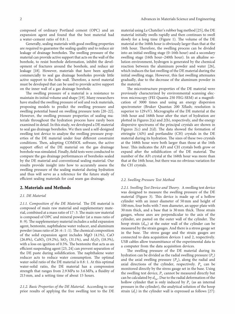
-e microstructure properties of the DE material werepreviously characterized by environmental scanning elec-tron microscopy (FEI Quanta 250 FEG-SEM) at a magnifi-cation of 3000 times and using an energy dispersionspectrometer (Bruker Quantax 200 Xflash resolution issuperior to 129 eV) Micrographs of the DE material at the16th hour and 168th hour after the start of hydration areplotted in Figures 2(a) and 2(b) respectively and the energydispersive spectrums of the principal crystals are shown inFigures 2(c) and 2(d) -e data showed the formation ofettringite (AFt) and portlandite (CH) crystals in the DEmaterial during its hydration -e sizes of these two crystalsat the 168th hour were both larger than those at the 16thhour -is indicates the AFt and CH crystals both grow orexpand after the solidification of the DE material -enumber of the AFt crystal at the 168th hour was more thanthat at the 16th hour but there was no obvious variation forthe CH crystals
22 Swelling Pressure Test Method
221 Swelling Test Device and-eory A swelling test devicewas designed to measure the swelling pressure of the DEmaterial (Figure 3) -is device is made up of a hollowcylinder with an inner diameter of 50mm and height of100mm four bolts with 7mm diameter an upper plate with30mm thick and a base that is 30mm thick -ree straingauges whose axes are perpendicular to the axis of thecylinder are pasted on the outer wall of the cylinder -ehoop strain (dtw) at the outer wall of the cylinder can bemeasured by the strain gauges And there is a stress gauge setin the base -e stress gauge and the strain gauges areconnected to data acquisition devices 1 and 2 respectivelyUSB cables allow transmittance of the experimental data toa computer from the data acquisition devices
-e swelling pressure of the DE material during itshydration can be divided as the radial swelling pressure (Pr)and the axial swelling pressure (Pa) along the radial andaxial directions of the cylinder respectively Pa can bemonitored directly by the stress gauge set in the base Usingthe swelling test device Pr cannot be measured directly butcan be calculated by dtw Due to the radial deformation of thehollow cylinder that is only induced by Pr (as an internalpressure in the cylinder) the analytical solution of the hoopstrain (dt) in the cylinder wall is expressed as follows [27]
2 Advances in Materials Science and Engineering
CH
AFt
(a)
CHAFt
(b)
30
25
20
15
10
05
00
cps (
eV)
0 2 4 6 8 10Energy (keV)
Au
O
Ca
(c)
30
25
20
15
10
05
00
cps (
eV)
Energy (keV)0 1 2 3 4 5 6 7 8 9 10
Au
O Si
Al S
Ca
(d)
Figure 2 -e micrographs of the DE material and the EDS of the CH and Aft crystals (a) micrograph at the 16th hour (b) micrograph atthe 168th hour (c) EDS of CH crystal (d) EDS of AFt crystal
16
14
12
10
8
6
4
2
Free
swel
ling
ratio
()
0 25 50 75 100 125 150 175 200 225 250Time (hour)
Secondary swelling
Photograph at the 168th hour free swelling
ratio of 154
Photograph at the 16th hour free swelling
ratio of 97
Initial swelling
Figure 1 Free swelling ratio of the DE material during hydration with macrographs of the material at the 16th hour and the 168th hour
Advances in Materials Science and Engineering 3
dt 1 + μ
E
Pr middot r2c
r0 + δ( 11138572 minus r2c
1minus 2μ +r0 + δ( 1113857
2
r21113888 1113889 (1)
where E and μ are Youngrsquos modulus and the Poisson ratio ofthe cylinder material respectively rc is the elastic-plasticcritical radius in the cylinder r0 is the inner radius of thecylinder δ is the thickness of the cylinder r0 + δ is the initialouter radius of the cylinder and r is the distance to the axisof the cylinder
-e swelling pressure of the DE material is far less thanthe yield strength of the cylinder material (355MPa)-erefore the entire cylinder remains elastic and we canobtain
rc r0 (2)
Incorporating (2) into (1) the hoop strain of the cylindercan be rewritten as
dt 1 + μ
E
Pr middot r20
r0 + δ( 11138572 minus r20
1minus 2μ +r0 + δ( 1113857
2
r21113888 1113889 (3)
-en dtw can be expressed as
dtw dt
1113868111386811138681113868rr0+δ 1 + μ
E
2Pr middot r20
r0 + δ( 11138572 minus r20
(1minus μ) (4)
-erefore Pr can be derived as
Pr E r0 + δ( 1113857
2 minus r201113872 1113873 middot dtw
2 1minus μ2( 1113857r20 (5)
222 Test Procedure Using the swelling test device theswelling pressure test procedure can be summarized as follows
(i) Test device connection -e swelling test devicedata acquisition devices and computer were con-nected according to Figure 3 -e upper plate wasnot installed at this step
(ii) DE paste preparation According to GBT 1346-2011 500 grams of the DE material and 400 gramsof water were stirred twice in a slurry agitator at25degC -e first stirring is performed at a rate of140 rmin for 120 s-en stirring is stopped for 15 sFinally the second stirring is performed at a rate of285 rmin for 120 s
(iii) Monitoring of swelling parameters and data pro-cessing After DE paste sample preparation the pastesample was immediately transported into the hollowcylinder When the cylinder was full the upper platewas installed on the cylinder and fixed by bolts andnuts (Figure 3) -en the swelling parameters of Paand dtw were monitored by the computer via the dataacquisition devices for 240 hours Finally using (5)Pr could be calculated using dtw
223 Test Scheme With swelling the DE material wasconstrained radially by the hollow cylinder and constrainedaxially by the bolts We aimed to investigate the swellingpressures of the DE material in four hollow cylinders ofdifferent dimensions and different radial constraint stiffness(Sr) However the axial constraint stiffness (Sa) of the boltswas maintained constant at 1268MPamiddotm2 Table 1 lists theconstraint stiffness used in the four tests
3 Results and Discussion
31 Time-Dependent Behavior of Swelling Pressure -eswelling pressure of the DE material exhibited a significanttime-dependent characteristic during its hydration asshown in Figure 4 -e swelling pressures including Pr andPa increased over time initially and then tended to be stablegradually For instance in test no 1 (Sr 412MPamiddotm2 andSa 1268MPamiddotm2) Pr and Pa are 063MPa and 049MPa at34 hours after the starting hydration of the DE material(Figure 4(a)) -en Pr and Pa rapidly increased between the
Data acquisition device 2
Data acquisition device 1
USB
cabl
e
ComputerUSB cable
Datawire
100 m
m
Swelling test device
Data wire
30 mm
30 mmStress gauge
Figure 3 Swelling test device and the connections with the computer and data acquisition devices
4 Advances in Materials Science and Engineering
34th hour and the 83rd hour Finally Pr and Pa increasedslowly and reached the stable values of 158MPa and137MPa respectively -e stable value is the maximumswelling pressure (MSP) For the other tests the tendency ofthe swelling pressure to vary over time is consistent with that
in test no 1-e time-dependent swelling pressure of the DEmaterial agrees with the results of Shi [28 29]
-e time (tm) to reach the maximum radial swellingpressure (MSP-r) is similar to that of the maximum axialswelling pressure (MSP-a) Specifically tm is about 1165 hours
30
25
20
15
10
05
00
Swel
ling
pres
sure
(MPa
)
0 50 100 150 200 250Time (hour)
Pr
Pa
1-Pr-T fitting curve1-Pa-T fitting curve
(a)
30
25
20
15
10
05
00
Swel
ling
pres
sure
(MPa
)
0 50 100 150 200 250Time (hour)
Pr
Pa
2-Pr-T fitting curve2-Pa-T fitting curve
(b)
30
25
20
15
10
05
00
Swel
ling
pres
sure
(MPa
)
0 50 100 150 200 250Time (hour)
Pr
Pa
3-Pr-T fitting curve3-Pa-T fitting curve
(c)
30
25
20
15
10
05
00
Swel
ling
pres
sure
(MPa
)
0 50 100 150 200 250Time (hour)
Pr
Pa
4-Pr-T fitting curve4-Pa-T fitting curve
(d)
Figure 4 Variations of swelling pressure over time (a) radial and axial swelling pressures-time curves in test no 1 (b) radial and axialswelling pressures-time curves in test no 2 (c) radial and axial swelling pressures-time curves in test no 3 (d) radial and axial swellingpressures-time curves in test no 4
Table 1 Constraint stiffness in the four tests
Test no δ (mm) rblowast (mm) Sr (MPamiddotm2) Sa (MPamiddotm2)1 2 7 412 12682 3 7 618 12683 4 7 824 12684 5 7 103 1268lowastRadius of the bolt
Advances in Materials Science and Engineering 5
in test no 1 166 hours in test no 2 201 hours in test no 3 and131 hours in test no 4 However there is also a difference in thevalues of tm for different tests For Srlt 824MPamiddotm2 tm in-creased with Sr However for Sr 824MPamiddotm2 in test no 4 thevalue of tm decreased significantly As discussed in Section212 formation and growth of AFt and CH occurs in the DEmaterial after solidification Furthermore based onmany priorstudies [30ndash35] the continuous formation and growth of AFtis a major contributor to the swelling of many inorganicmaterials -e chemical reaction of forming AFt is as follows
6Ca2++ 2Al(OH)
minus4 + 4OHminus + 3SO 2minus
4 + 26H2O
⟶ Ca6 Al(OH)61113858 11138592 middot SO4( 11138573 middot 26H20(AFt)(6)
From (6) it is clear that the formation and growthprocess of AFt is influenced by the transmission of ions inthe DE material After the hardening of the DE materialwith aluminum calcium and sulfate ions present in thepores that continued to concentrate around the AFt the AFtforms and grows over time [31ndash33] A counterforce from theconstraint is imposed on the DE material -e counterforcehas a positive correlation with the swelling pressure andincreases with Sr Pores in the DE material may be partiallycompressed under the counterforce which hinders ionmigration and prolongs the formation and growth process ofAFt When Sr increases to 824MPamiddotm2 the swelling pres-sure becomes much larger -erefore the pores in the DEmaterial may be compressed further or be completely undera relatively high counterforce which may drive some of theions that are migrating from pores to gather together -eformation and growth progress of AFt will be much shorter-erefore the tm of test no 4 was less than that of test nos 2and 3 However the critical counterforce which reduces tmwas not determined in this study
-e time-dependent behavior of the swelling pressure isshown in Figure 4 and can be applied to evaluate the stabilityof a coal seam borehole and to estimate air leakage [18] Tomathematically describe the time-dependent behavior of theswelling pressure (7a) was introduced for nonlinear fitting
P A2 +A1 minusA2
1 + exp((tminus a)1113870b) (7a)
where A1 A2 a and b represent the fitting parameters and t
is timeAfter nonlinear fitting the fitting parameters are listed in
Table 2 -e correlation coefficients between the fittingequation and the experimental data are larger than 098-erefore (7a) can be used to accurately describe the time-dependent behavior of the swelling pressure Moreoverfrom the fitting results it can be seen that the fitting pa-rameter A2 roughly coincides with MSP and the parameterA1 is close to 0 Hence the time-dependent behavior of theswelling pressure can be described as
P MSP middotexp((tminus a)1113870b)
1 + exp((tminus a)1113870b) (7b)
32 Radial Swelling Potential at Each Stage Based on theresults of the swelling pressure tests the radial swellingpressures produced at different swelling stages are plotted in
Figure 5 -e radial swelling pressures were less than0125MPa at the initial swelling stage (0ndash16th hour) How-ever the radial swelling pressures produced at the secondaryswelling stage (17th hourndash240th hour) are 1526MPa1614MPa 2057MPa and 208MPa in test nos 1 2 3 and 4respectively -is result indicates that the radial swellingpressure produced at the secondary swelling stage is largerthan that at the initial swelling stage and increases with Sr
In practice the swelling potential of the DE materialenergy is released radially and axially and it is the radialswelling potential that is a key for the active support actingon the gas drainage borehole wall For the laboratory teststhe radial swelling pressure as an internal pressure doeswork to the hollow cylinder and then elastic energy (WH) issaved in the hollow cylinder Hence WH can be adopted toassess the radial swelling potential of the DE material In thispaper we define WH as the radial swelling potential index(RSPI) of the DEmaterial Based on the elastic theory and byapplying the integration method the WH and the RSPI canbe expressed as follows (Appendix A)
WH RSPI 1113946r0+δ
r0
11139462π
0
A
rB +
C
r21113874 1113875dφ dr
A P2rr
30L0(1 + μ)
2δE
B 1minus 2μ
C r0 + δ( 11138572
(8)
-e RSPI of the DE material at different swelling stages isillustrated in Figure 6-e values of RSPI at the initial swellingstage were 0147times10minus4 J 0155times10minus4 J 0421times 10minus4 J and0724times10minus4 J in test nos 1 2 3 and 4 respectively Howeverthe values of RSPI at the secondary swelling stage were1258times10minus4 J 1379times10minus4 J 2244times10minus4 J and 2329times10minus4 Jfor the four tests showing that the values of RSPI increase withSr Furthermore the values of RSPI at the initial swelling stagewere much lower than those at the secondary swelling stage
In the initial swelling stage the swelling of the DEmaterial is mainly caused by the foaming effect of thealuminum powder-en a porous structure is formed in theDE material as shown schematically in Figure 7(a) whichincludes pores calcium silicate hydrates (C-S-H) AFtcrystals and CH crystals -e AFt and CH crystals formed at
Table 2 Fitting parameters of the fitting curves
Fittingcurves A1 A2 a b R2
1-Pr-T minus027 158 4131 2148 09911-Pa-T 003 137 4943 2439 09902-Pr-T minus009 168 9177 3100 09872-Pa-T minus008 153 9177 3100 09873-Pr-T minus142 215 2867 4957 09863-Pa-T minus034 197 6646 4575 09934-Pr-T minus035 221 4748 2259 09974-Pa-T minus033 209 4748 2259 0997
6 Advances in Materials Science and Engineering
this stage do not play a role in the swelling of the DEmaterial but they do enhance the strength of the material inthis initial phase [36] -e swelling potential caused by thefoaming effect is very low and due to the compressibility ofthe porous structure at this stage the swelling potentialenergy can be easily absorbed by the compression of thepores -at is why the value of the RSPI is very low at thisstage However the fast swelling in this initial swelling stageensures that the gas drainage borehole is sealed quickly
In the secondary swelling stage the DE material has beensolidified -e schematic for the morphology model of hy-drates of the DE material in the secondary swelling stage isillustrated in Figure 7(b)-e pores become smaller than thoseat the 16th hour and the AFt and CH crystals become larger-e swelling is mainly caused by the formation or growth ofthe crystals which exert a notable pressure on the surroundingmedium [3537ndash39] When there is a slight radial deformationof the hollow cylinder much elastic energy will be stored in the
cylinder -erefore the radial swelling potential of the DEmaterial is mainly formed in the secondary swelling stagecausing main active support on the radial constraint
33 Active Support Effect of DE Material for a GasDrainage Borehole
331 Coal Creep Model and Validation
(1) Creep Model of Coal Coal is a typical viscoelastic-plasticmedium [40] It is necessary to consider its creep property tostudy the stability of the borehole In this study a creepmodel consisting of Burgers body (Kelvin body in series withMaxwell body) in series with a plastic element was adopted-e Burgers body reflects the viscoelastic deformation of coaland the plastic element controls the failure of coal which isdetermined by the MohrndashCoulomb yield criterion F
RSPI at the initial swelling stageRSPI at the secondary swelling stage
30
25
20
15
10
5
0
RSPI
(10ndash4
∙J)
Test no1 Test no2 Test no3 Test no4
Figure 6 RSPI at different swelling stages
30
25
20
15
10
05
00
Pres
sure
(MPa
)
Test no 1 Test no 2 Test no 3 Test no 4
Radial swelling pressure at the initial swelling stageRadial swelling pressure at the secondary swelling stage
Figure 5 Radial swelling pressures produced at different swelling stages
Advances in Materials Science and Engineering 7
F σ1 minus1 + sin ϕ1minus sin ϕ
σ3 minus σs (9)
where σ1 and σ3 are the maximum and minimum principalstresses φ is the internal friction angle and σs is the uniaxialcompressive strength
For Flt 0 the plastic element does not work -e creepequation of coal in the viscoelastic deformation stage can beexpressed as follows [41]
eveij(t)
Sij
2GM+
Sij
2ηMt +
Sij
2GK1minus eminus GKηK( )t
1113874 1113875 (10)
where eveij(t) is the deviatoric strain tensor at the viscoelastic
deformation stage Sij is the deviatoric stress tensor G and ηare the shear modulus and the viscosity coefficient re-spectively and the subscripts ldquoMrdquo and ldquoKrdquo represent theMaxwell body and Kelvin body in the Burgers body
Assuming the coal is an isotropic material the elasticconstitutive relation can be expressed as follows
Sij 2Geij
σm 3Kεm(11)
Sij σij minus σmδij
eij εij minus εmδij(12)
where K is the bulk modulus σij and εij are stress and straintensors respectively σm σkk3 and εm εkk3 representthe average normal strain and stress respectively and δij isthe Kronecker delta
Incorporating (11) and (12) into (10) the viscoelasticstrain in three dimensions is obtained as
εveij σij minus σmδij1113872 1113873
middot1
2GM+
12ηM
t +1
2GK1minus eminus GKηK( )t
1113874 11138751113890 1113891 +σm
3K
(13)
For F 0 based on the nonassociated flow rule the strainincrement of the plastic element can be expressed as follows
dεpij dλ
zQ
zσij
(14)
where dλ is the plastic multiplier and Q is the plastic po-tential function which is expressed as follows
Q σ1 minus1 + sin ψ1minus sin ψ
σ3 minus2c cos ψ1minus sin ψ
(15)
where c is the cohesion of coal and ψ is the dilatation angle
(2) Model Verification To verify the proposed creep modelthe creep behavior of the coal sample from the no 2 coalseam in Huangling no 2 coal mine was tested under triaxialstress condition (σ1 7MPa and σ2 σ3 3MPa) In ac-cordance with (13) and the experimental data the creepparameters of the coal were obtained -en (13) wasimplemented into the solid mechanics module of theCOMSOL Multiphysics software as a viscoelastic constitu-tive equation Combining the built-in plastic model of thesolid mechanics module the creep deformation under thesame triaxial stress condition was simulated -e parametersused in the simulation are listed in Table 3 which are fromthe experimental results -e simulated results and theexperimental data are plotted in Figure 8 -e comparisonshows that the creep model presented in this study candescribe the coal samplersquos creep curve which includesa transient creep stage a decelerating creep stage a steadycreep stage and an accelerating stage
332 Simulation of Gas Drainage Borehole Stability
(1) Physical Model and Boundary Conditions As shown inFigure 9 the physical model is 2m in height and 2m inwidth and the diameter of the borehole is 01m AB BC andAD have a constant normal stress boundary conditionP0 10MPa -e DC is under a fixed boundary conditionUx Uy 0 -e simulation was conducted under two kindsof stress boundary conditions of the borehole (1) no active
CH
C-S-H
Pore
AFt
(a)
Pore AFt
CH
C-S-H
(b)
Figure 7 Schematic for the morphology model of hydrates in the DE material (a) initial swelling stage (b) secondary swelling stage
8 Advances in Materials Science and Engineering
support imposed on the hole wall and (2) an active supportS1 imposed on the inner wall of the borehole which is fromthe swelling of the DE material and can be assumed aspresented in the following equation -e parameters in thissimulation are chosen from Table 3
S1 15 middotexp((Tminus 40)111387020)
1 + exp((Tminus 40)111387020) (16)
(2) Borehole Stability Analysis -e vertical stress distribu-tion around a gas drainage borehole is illustrated in Fig-ure 10 -e vertical stress near the hole wall is lower than thein situ stress which indicates damage to the coal that is closeto the borehole after borehole excavation -is damageregion extends over time For the borehole sealed withoutactive support the maximum damage distance to the holewall was 47mm one day after drilling excavation For 2 daysand 5 days after borehole drilling the maximum damagedistance increased to 96mm and 123mm respectivelyHowever when the active support S1 was imposed on thehole wall the maximum damage distances were reduced to24mm 37mm and 51mm at the 1st day 2nd day and 5thday after drilling excavation
Figure 11 illustrates the distribution of the plastic regionaround the borehole -e plastic region also extends overtime but shrinks when the active support is imposed on theborehole wall Without active support on the hole wall theradii of the plastic regions were 129mm 220mm and246mm for 1 day 2 days and 5 days after drilling re-spectively However with active support S1 the radii of theplastic regions were reduced to 121mm 165mm and183mm for 1 day 2 days and 5 days after drillingrespectively
-e stability of the borehole weakens over time due tothe creep of the coal which is consistent with the results ofLiu and Paraschiv-Munteanu et al [42 43] However theactive support imposed on the borehole can efficiently limitthe enlargement of the damage region and the plastic regionresulting in improved stability of the gas drainage borehole-erefore the borehole sealed by the DE material is morestable than that sealed by materials lacking swelling pressure
4 Field Tests
41 Field Situation To compare the gas drainage boreholesealing effect for the DE material and a conventional materialfield tests were carried out at panel 207 of Huangling no 2 coalmine in China -e buried depth of the panel 207 is 369mndash413m and the dip angle ranges from 4deg to 7deg -e gas pressureof the panel is 029MPandash151MPa and the gas content rangesfrom 675m3t to 1452m3t-e coal seam permeability in thispanel is measured as 67times10minus17m2sim36times10minus16m2 witha mean value of 25times10minus16m2 -e conventional sealingmaterial used for the field test consisted of OPC water reducerand aluminum powder (mass ratio of 1 0006 0002) -ismaterial has a free swelling ratio of 15 and a maximumswelling pressure of 50 kPa under a water-solid ratio of 06 1In this panel forty coal seam boreholes were prepared anddivided into two groups-e boreholes in Group 1 were sealedby the DE material and the boreholes in Group 2 were sealedby the conventional sealing material -e sealing length of thegas drainage borehole in the panel 207 is 16m After sealing
8
7
6
5
4
3
2
1
0
Axi
al st
rian
(permil)
4 8 12 16 20 24 28 32 36 40Time (hour)
Simulated resultExperimental data
Figure 8 Comparison between experimental data and simulatedresults
P0
P0
P0
A B
CD
2 m
2 m
Drilling position atdiameter of 01 m
Figure 9 Physical model and boundary conditions
Table 3 Parameters of the coal from Huangling no 2 coal mine
Density (gcm3) GM (GPa) Gk (GPa) ηM (MPamiddoth) ηK (MPamiddoth) c (MPa) ψ (deg) φ (deg)138 194 326 1175 102 085 17 315
Advances in Materials Science and Engineering 9
137
12
10
8
6
4
2162
(a)
135
12
10
8
6
4
2021
(b)
137
ndash117
12
10
8
6
4
2
0
(c)
157
139
12
10
8
6
4
2
(d)
061
138
12
10
8
6
4
2
(e)
ndash006
138
12
10
8
6
4
2
0
(f )
Figure 10 Distribution of vertical stress around borehole (a) No active support 1d (b) No active support 2d (c) No active support 5d (d)Active support S1-1d (e) Active support S1-2d (f ) Active support S1-5d
10908070605040302010
1
0
(a)
10908070605040302010
1
0
(b)
10908070605040302010
1
0
(c)
Figure 11 Continued
10 Advances in Materials Science and Engineering
the boreholes were connected to the drainage net with a neg-ative drainage pressure of minus15 kPa
42GasDrainagePerformanceComparison Figure 12 showsthe gas concentrations recorded in the drainage process for 50days On the first day the gas drainage concentrations were48 and 47 in Group 1 and Group 2 respectively -en inGroup 2 the gas concentration attenuated very fast changingfrom 47 to 4 during 50 days However in Group 1 the gasconcentration decreased slowly from 48 to 32-roughout the whole drainage process the average gasconcentration of Group 1 was 391 more than twice theaverage concentration (17) of Group 1 Field tests resultsrevealed no discernible difference between the sealing effect ofthe conventional sealing material and the DE material at thebeginning stage However throughout the entire drainageprocess the active support from the DE material significantlyimproved the gas drainage performance compared with theborehole sealed using the conventional sealing material
5 Conclusions
To improve coal seam gas drainage performance we de-veloped a DE material for borehole sealing -is material iscomposed of OPC mineral powder a solid expansion agentbentonite naphthalene water reducer and aluminumpowder -e swelling process of the DE material includes aninitial swelling stage affected by the foaming effect of thealuminum powder and a secondary swelling stage inducedby the growth and formation of the crystals According tothe results the key conclusions are summarized as follows
(1) -e swelling test device was used to test the swellingpressure of the DE material under four constraintconditions -e swelling pressure properties of theDE material revealed that (a) the swelling pressure ofthe DE material is time-dependent during its hy-dration and the relationship described here of theswelling pressure and time can describe this time-dependent behavior accurately and (b) the radialswelling potential is principally formed during thesecondary swelling stage
(2) -e stability of a gas drainage borehole weakens overtime due to the creep of the coal However the activesupport imposed on the hole wall can efficientlyinhibit the enlargement of the damage region and theplastic region for improved stability of the gasdrainage borehole
(3) Field tests results show significantly improved gasdrainage performance of the borehole sealed by theDE material -e DE-sealed borehole had an averagegas concentration in 50 days of 391 more thantwice that of the borehole sealed by the conventionalsealing material
Appendix
A Derivation Process of (8)
With the swelling of the DE material the radial swellingpressure does work to the hollow cylinder Part of the radial
109080706050403020100
1
(d)
10908070605040302010
0
1
(e)
10908070605040302010
0
1
(f )
Figure 11 Distribution of the plastic region around the borehole (a) No active support 1d (b) No active support 2d (c) No active support5d (d) Active support S1-1d (e) Active support S1-2d (f ) Active support S1-5d
00
10
20
30
40
50
Group 1Group 2
10 20 30Predrainage time (day)
Conc
entr
atio
n (
)
40 50
Figure 12 Gas drainage concentrations in the field test
Advances in Materials Science and Engineering 11
swelling potential is converted to elastic deformation energyand is saved in the cylinder and this can be calculated by theintegration method As shown in Figure 13 the hollow cyl-inder can be divided into numerous unit hollow cylinderswhose thicknesses are all dr -e unit hollow cylinder iscomposed of numerous rectangular units with length of r middot dφand width of dr -erefore the elastic deformation energystored in the hollow cylinder and the RSPI can be expressed as
RSPI WH 1113946r0+δ
r0
11139462π
0WR (A1)
where WR represents the elastic deformation energy saved ina rectangular unit
Based on the elastic theory the stresses and strains in therectangular unit can be expressed as
Prminus1 minusPrminus1 Pr middotr20r2
εrminus1 minusεrminus2 minusdt
(A2)
where Prminus1 and Prminus2 are the normal and tangential principalstresses respectively and εrminus1 and εrminus2 are the normal andtangential principal strains It should be noted that the stressand strain along the axis of the cylinder are both 0-erefore the elastic deformation energy saved in therectangular unit can be calculated as follows
WR WR1 + WR2
WR1 12L0Prminus1εrminus1r dφdr
WR2 12L0Prminus2εrminus2r dφdr
(A3)
where WR1 and WR2 represent the normal and tangentialelastic deformation energies respectively
Incorporating (A2) into (A3) we can obtain
WR PrL0r20dt
rdr dφ (A4)
where L0 is the length of the hollow cylinder and is equal to100mm
-en combining with (3) (A4) can be rewritten as
WR A B +C
r21113874 1113875
dφ dr
r
A P2
rr30L0(1 + μ)
2δE
B 1minus 2μ
C r0 + δ( 11138572
(A5)
Finally incorporating (A5) into (A1) we can obtain
WH RSPI 1113946r0+δ
r0
11139462π
0
A
rB +
C
r21113874 1113875dφ dr
A P2
rr30L0(1 + μ)
2δE
B 1minus 2μ
C r0 + δ( 11138572
(A6)
Data Availability
No data were used to support this study
Conflicts of Interest
-e authors declare that there are no conflicts of interestregarding the publication of this paper
Acknowledgments
-is work was supported by the Henan Province Science andTechnology Innovation Talent Program (no 164200510002)
Supplementary Materials
A dataset is provided as supplementary materials whichincludes the experimental results of free swelling ratio EDSdata and swelling pressure of the DEmaterial and the valuesof RSPI calculated (Supplementary Materials)
References
[1] Z J Pan and D A Wood ldquoCoal bed methane (CBM) ex-ploration reservoir characterisation production and mod-elling a collection of published research (2009ndash2015)rdquoJournal of Natural Gas Science and Engineering vol 26 no 1pp 1472ndash1484 2015
[2] K Baris C Keles N Ripepi et al ldquo-e first commercial coalbed methane project in Turkey-Reservoir simulation andprefeasibility study for the Amasra coalfieldrdquo InternationalJournal of Oil Gas and Coal Technology vol 13 no 2pp 170ndash199 2016
r0
r0 + δ
Pr
r
Prndash2
Prndash2
Prndash1Prndash1
Unit hollow cylinder
Rectangular unit
Figure 13 Unit division of the hollow cylinder
12 Advances in Materials Science and Engineering
[3] N Ripepi K Louk J Amante C Schlosser X Tang andE Gilliland ldquoDetermining coalbed methane production andcomposition from individual stacked coal seams in a multi-zone completed gas wellrdquo Energies vol 10 no 10 p 15332017
[4] J Hansen and A Lacis ldquoSun and dust versus greenhousegases an assessment of their relative roles in global climatechangerdquo Nature vol 346 no 6286 pp 713ndash719 1990
[5] K Warmuzinski ldquoHarnessing methane emissions from coalminingrdquo Process Safety and Environmental Protection vol 86no 5 pp 315ndash320 2008
[6] T Xia F Zhou J Liu and F Gao ldquoEvaluation of the pre-drained coal seam gas qualityrdquo Fuel vol 130 pp 296ndash3052014
[7] Y Gao B Q Lin W Yang et al ldquoDrilling large diametercross-measure boreholes to improve gas drainage in highlygassy soft coal seamsrdquo Journal of Natural Gas Science andEngineering vol 26 pp 193ndash204 2015
[8] J Jiang Y Cheng P Zhang et al ldquoCBM drainage engineeringchallenges and the technology of mining protective coal seamin the Dalong Mine Tiefa Basin Chinardquo Journal of NaturalGas Science and Engineering vol 24 pp 412ndash424 2015
[9] Y Chen J Xu S Peng F Yan and C Fan ldquoA gasndashsolidndashliquid coupling model of coal seams and the optimization ofgas drainage boreholesrdquo Energies vol 11 no 3 p 560 2018
[10] T Q Xia F B Zhou J S Liu S Y Hu and Y K Liu ldquoA fullycoupled coal deformation and compositional flow model forthe control of the pre-mining coal seam gas extractionrdquoInternational Journal of Rock Mechanics and Mining Sciencesvol 72 pp 138ndash148 2014
[11] X W Xiang C Zhai Y Xu and J Z Xu ldquoA flexible gelsealing material and a novel active sealing method for coal-bed methane drainage boreholesrdquo Journal of Natural GasScience and Engineering vol 26 pp 1187ndash1199 2015
[12] C Zheng M S Kizil Z Chen and S M AminossadatildquoEffects of coal properties on ventilation air leakage intomethane gas drainage boreholes application of the orthog-onal designrdquo Journal of Natural Gas Science and Engineeringvol 45 pp 88ndash95 2017
[13] H Farzaneh M Fahimi and Y Saboohi ldquoOptimal powergeneration from low concentration coal bed methane in IranrdquoEnergy Sources Part A Recovery Utilization and Environ-mental Effects vol 38 no 4 pp 590ndash596 2016
[14] F B Zhou J Li X Ze et al ldquoA study of the second holesealing method to improve gas drainage in coal seamsrdquoJournal of China University of Mining and Technology vol 38no 6 pp 764ndash768 2009
[15] F B Zhou Y N Sun H J Li and G Yu ldquoResearch on thetheoretical model and engineering technology of the coalseam gas drainage hole sealingrdquo Journal of China University ofMining and Technology vol 45 no 3 pp 433ndash439 2016
[16] C Zhai X W Xiang Q L Zou X Yu and Y Xu ldquoInfluencefactors analysis of a flexible gel sealing material for coal-bedmethane drainage boreholesrdquo Environmental Earth Sciencesvol 75 no 5 pp 1ndash13 2016
[17] Q Q Liu Y P Cheng L Yuan et al ldquoA new effective methodand new materials for high sealing performance of cross-measure CMM drainage boreholesrdquo Journal of Natural GasScience and Engineering vol 21 pp 805ndash813 2014
[18] Z F Wang Y Zhou Y N Sun and Y L Wang ldquoNovel gasextraction borehole grouting sealing method and sealingmechanismrdquo Journal of China Coal Society vol 40 no 3pp 588ndash595 2015
[19] F Shuai Simulation of swelling pressure measurements onexpansive soils PhD dissertation University of Saskatch-ewan Saskatchewan Canada 1996
[20] L Liu ldquoPrediction of swelling pressures of different types ofbentonite in dilute solutionsrdquo Colloids and Surfaces APhysicochemical and Engineering Aspects vol 434 no 19pp 303ndash318 2013
[21] C Butscher S Scheidler H Farhadian H Dresmann andP Huggenberger ldquoSwelling potential of clay-sulfate rocks intunneling in complex geological settings and impact of hy-draulic measures assessed by 3D groundwater modelingrdquoEngineering Geology vol 221 pp 143ndash153 2017
[22] R Bag and A Rabbani ldquoEffect of temperature on swellingpressure and compressibility characteristics of soilrdquo AppliedClay Science vol 136 pp 1ndash7 2017
[23] G Montesh ldquoSwellingndashshrinkage measurements of bentoniteusing coupled environmental scanning electron microscopyand digital image analysisrdquo Journal of Colloid and InterfaceScience vol 284 no 1 pp 271ndash277 2005
[24] M Bradbury and B Baeyens ldquoExperimental and modellingstudies on the pH buffering of MX-80 bentonite porewaterrdquoApplied Geochemistry vol 24 no 3 pp 419ndash425 2009
[25] E Tazawa S Miyazawa and T Kasai ldquoChemical shrinkageand autogenous shrinkage of hydrating cement pasterdquo Ce-ment and Concrete Research vol 25 no 2 pp 288ndash292 1995
[26] N Nasir R Jumaidin H Efendy et al ldquoPreparation ofmacroporous ceramic materials by using aluminium powderas foaming agentrdquo Applied Mechanics and Materials vol 699pp 336ndash341 2014
[27] X Gao ldquoElasto-plastic analysis of an internally pressurizedthick-walled cylinder using a strain gradient plasticity theoryrdquoInternational Journal of Solids and Structures vol 40 no 23pp 6445ndash6455 2003
[28] H Shi G Chen Y Xiao W Yu and Y Yuan ldquoMineraladditives and expansion behaviors of hardened cement pasterdquoJournal of Building Materials vol 2 no 4 pp 344ndash348 1999
[29] H Shi G Chen and W Yu ldquoExpansion behavior and stressmatch of hardened cement pastesrdquo Journal of Tongji Uni-versity vol 25 no 6 pp 690ndash694 1997
[30] D Dermatas ldquoEttringite-induced swelling in soils state-of-the-artrdquo Applied Mechanics Reviews vol 48 no 10pp 659ndash675 1995
[31] D H Moon D Dermatas M Wazne A M SanchezM Chrysochoou and D G Grubb ldquoSwelling related toettringite crystal formation in chromite ore processing resi-duerdquo Environmental Geochemistry and Health vol 29 no 4pp 289ndash294 2007
[32] H F W Taylor C Famy and K L Scrivener ldquoDelayedettringite formationrdquo Cement and Concrete Research vol 31no 5 pp 683ndash693 2001
[33] D Damidot M Atkins and F P Glasser ldquoPhase developmentin cement in relation to the secondary ettringite problemrdquoAdvances in Cement Research vol 7 no 26 pp 57ndash68 1995
[34] I Odler and J C Subauste ldquoInvestigations on cement ex-pansion associated with ettringite formationrdquo Cement andConcrete Research vol 29 no 5 pp 731ndash735 1999
[35] P Yan F Zheng J Peng and X Qin ldquoRelationship betweendelayed ettringite formation and delayed expansion in mas-sive shrinkage-compensating concreterdquo Cement and ConcreteComposites vol 26 no 6 pp 687ndash693 2004
[36] P Akpinar and I Casanova ldquoA combined study of expansiveand tensile strength evolution of mortars under sulfate attackimplications on durability assessmentrdquo Materiales De Con-struccion vol 60 no 297 pp 59ndash68 2010
Advances in Materials Science and Engineering 13
[37] A Pavoine L Divet and S Fenouillet ldquoA concrete perfor-mance test for delayed ettringite formation part II valida-tionrdquo Cement and Concrete Research vol 36 no 12pp 2144ndash2151 2006
[38] A Ramon Expansion mechanisms in sulphated rocks and soilsPhD dissertation Universitat Politecnica de CatalunyaBarcelona Spain 2014
[39] R Chen and Z Chen ldquoStudy on the hydration kinetics of freeCaO in high calcium fly ashrdquo Journal of Building Materialsvol 2 pp 147ndash150 2000
[40] J Kang F Zhou C Liu and Y Liu ldquoA fractional nonlinearcreep model for coal considering damage effect and experi-mental validationrdquo International Journal of Non-Linear Me-chanics vol 76 pp 20ndash28 2015
[41] S Yang P Xu and P Ranjith ldquoEvaluation of creep me-chanical behavior of deep-buried marble under triaxial cyclicloadingrdquo Arabian Journal of Geosciences vol 8 no 9pp 6567ndash6582 2015
[42] C Liu F Zhou and J Kang ldquoApplication of a non-linearviscoelastic-plastic rheological model of soft coal on boreholestabilityrdquo Journal of Natural Gas Science and Engineeringvol 36 pp 1303ndash1311 2016
[43] I Paraschiv-Munteanu and N D Cristescu ldquoStress relaxationduring creep of rocks around deep boreholesrdquo InternationalJournal of Engineering Science vol 39 no 7 pp 737ndash7542001
14 Advances in Materials Science and Engineering
CorrosionInternational Journal of
Hindawiwwwhindawicom Volume 2018
Advances in
Materials Science and EngineeringHindawiwwwhindawicom Volume 2018
Hindawiwwwhindawicom Volume 2018
Journal of
Chemistry
Analytical ChemistryInternational Journal of
Hindawiwwwhindawicom Volume 2018
ScienticaHindawiwwwhindawicom Volume 2018
Polymer ScienceInternational Journal of
Hindawiwwwhindawicom Volume 2018
Hindawiwwwhindawicom Volume 2018
Advances in Condensed Matter Physics
Hindawiwwwhindawicom Volume 2018
International Journal of
BiomaterialsHindawiwwwhindawicom
Journal ofEngineeringVolume 2018
Applied ChemistryJournal of
Hindawiwwwhindawicom Volume 2018
NanotechnologyHindawiwwwhindawicom Volume 2018
Journal of
Hindawiwwwhindawicom Volume 2018
High Energy PhysicsAdvances in
Hindawi Publishing Corporation httpwwwhindawicom Volume 2013Hindawiwwwhindawicom
The Scientific World Journal
Volume 2018
TribologyAdvances in
Hindawiwwwhindawicom Volume 2018
Hindawiwwwhindawicom Volume 2018
ChemistryAdvances in
Hindawiwwwhindawicom Volume 2018
Advances inPhysical Chemistry
Hindawiwwwhindawicom Volume 2018
BioMed Research InternationalMaterials
Journal of
Hindawiwwwhindawicom Volume 2018
Na
nom
ate
ria
ls
Hindawiwwwhindawicom Volume 2018
Journal ofNanomaterials
Submit your manuscripts atwwwhindawicom
composed of ordinary Portland cement (OPC) and anexpansion agent and found that the best material hada water-cement ratio of 08 1
Generally sealing materials with good swelling propertiesare required to guarantee the sealing quality and to reduce airleakage of drainage boreholes -e swelling pressure of thematerial can provide active support that acts on the wall of theborehole to resist borehole deformation inhibit the devel-opment of fractures around the borehole and reduce airleakage [18] However materials that have been appliedcommercially to seal gas drainage boreholes provide littleactive support to the hole wall -erefore a novel materialmust be developed that can be used to provide active supporton the inner wall of a gas drainage borehole
-e swelling pressure of a material is a resistance tomaintain its initial volume and shape [19] Many researchershave studied the swelling pressure of soil and rock materialsproposing models to predict the swelling pressure andswelling potential based on swelling pressure tests [20ndash22]However the swelling pressure properties of sealing ma-terials throughout the hydration process have rarely beenexamined in detail In this study we developed a DEmaterialto seal gas drainage boreholes We then used a self-designedswelling test device to analyze the swelling pressure prop-erties of the DE material under four different constraintconditions -en adopting COMSOL software the activesupport effect of the DE material on the gas drainageborehole was simulated Finally field tests were conducted tocompare the gas drainage performances of boreholes sealedby the DE material and conventional sealing material Ourresults provide insight into how to accurately assess theswelling pressure of the sealing material during hydrationand thus will serve as a reference for the future study ofefficient sealing materials for coal seam gas drainage
2 Materials and Methods
21 DE Material
211 Composition of the DE Material -e DE material iscomposed of main raw material and supplementary mate-rial combined at amass ratio of 17 3-emain rawmaterialis composed of OPC and mineral powder (at a mass ratio of8 9)-e supplementary material includes a solid expansionagent bentonite naphthalene water reducer and aluminumpowder (mass ratio of 26 6 1 1)-e chemical compositionof the solid expansion agent includes MgO (41) CaO(268) CaSO4 (192) SiO2 (311) and Al2O3 (183)with a loss on ignition of 05 -e bentonite that acts as anefficient suspending agent [23 24] can prevent separation ofthe DE paste during solidification -e naphthalene waterreducer acts to reduce water consumption -e optimalwater-solid ratio of the DE material is 08 1 At this optimalwater-solid ratio the DE material has a compressionstrength that ranges from 29MPa to 36MPa a fluidity of213mm and a setting time of about 15 hours
212 Basic Properties of the DE Material According to ourprior results of applying the free swelling test to the DE
material using Le Chatelierrsquos rubber bagmethod [25] the DEmaterial initially swells rapidly and then continues to swellslowly for a long time (Figure 1) -e volume of the DEmaterial at the 168th hour is obviously larger than that at the16th hour -erefore the swelling process can be dividedinto an initial swelling stage (0ndash16th hour) and a secondaryswelling stage (16th hourndash240th hour) In an alkaline so-lution environment hydrogen is generated by the chemicalreaction between the aluminum powder and water [26]which induces the fast swelling of the DEmaterial during theinitial swelling stage However this fast swelling attenuatesgradually due to the decrease of the aluminum powder inthe material
-e microstructure properties of the DE material werepreviously characterized by environmental scanning elec-tron microscopy (FEI Quanta 250 FEG-SEM) at a magnifi-cation of 3000 times and using an energy dispersionspectrometer (Bruker Quantax 200 Xflash resolution issuperior to 129 eV) Micrographs of the DE material at the16th hour and 168th hour after the start of hydration areplotted in Figures 2(a) and 2(b) respectively and the energydispersive spectrums of the principal crystals are shown inFigures 2(c) and 2(d) -e data showed the formation ofettringite (AFt) and portlandite (CH) crystals in the DEmaterial during its hydration -e sizes of these two crystalsat the 168th hour were both larger than those at the 16thhour -is indicates the AFt and CH crystals both grow orexpand after the solidification of the DE material -enumber of the AFt crystal at the 168th hour was more thanthat at the 16th hour but there was no obvious variation forthe CH crystals
22 Swelling Pressure Test Method
221 Swelling Test Device and-eory A swelling test devicewas designed to measure the swelling pressure of the DEmaterial (Figure 3) -is device is made up of a hollowcylinder with an inner diameter of 50mm and height of100mm four bolts with 7mm diameter an upper plate with30mm thick and a base that is 30mm thick -ree straingauges whose axes are perpendicular to the axis of thecylinder are pasted on the outer wall of the cylinder -ehoop strain (dtw) at the outer wall of the cylinder can bemeasured by the strain gauges And there is a stress gauge setin the base -e stress gauge and the strain gauges areconnected to data acquisition devices 1 and 2 respectivelyUSB cables allow transmittance of the experimental data toa computer from the data acquisition devices
-e swelling pressure of the DE material during itshydration can be divided as the radial swelling pressure (Pr)and the axial swelling pressure (Pa) along the radial andaxial directions of the cylinder respectively Pa can bemonitored directly by the stress gauge set in the base Usingthe swelling test device Pr cannot be measured directly butcan be calculated by dtw Due to the radial deformation of thehollow cylinder that is only induced by Pr (as an internalpressure in the cylinder) the analytical solution of the hoopstrain (dt) in the cylinder wall is expressed as follows [27]
2 Advances in Materials Science and Engineering
CH
AFt
(a)
CHAFt
(b)
30
25
20
15
10
05
00
cps (
eV)
0 2 4 6 8 10Energy (keV)
Au
O
Ca
(c)
30
25
20
15
10
05
00
cps (
eV)
Energy (keV)0 1 2 3 4 5 6 7 8 9 10
Au
O Si
Al S
Ca
(d)
Figure 2 -e micrographs of the DE material and the EDS of the CH and Aft crystals (a) micrograph at the 16th hour (b) micrograph atthe 168th hour (c) EDS of CH crystal (d) EDS of AFt crystal
16
14
12
10
8
6
4
2
Free
swel
ling
ratio
()
0 25 50 75 100 125 150 175 200 225 250Time (hour)
Secondary swelling
Photograph at the 168th hour free swelling
ratio of 154
Photograph at the 16th hour free swelling
ratio of 97
Initial swelling
Figure 1 Free swelling ratio of the DE material during hydration with macrographs of the material at the 16th hour and the 168th hour
Advances in Materials Science and Engineering 3
dt 1 + μ
E
Pr middot r2c
r0 + δ( 11138572 minus r2c
1minus 2μ +r0 + δ( 1113857
2
r21113888 1113889 (1)
where E and μ are Youngrsquos modulus and the Poisson ratio ofthe cylinder material respectively rc is the elastic-plasticcritical radius in the cylinder r0 is the inner radius of thecylinder δ is the thickness of the cylinder r0 + δ is the initialouter radius of the cylinder and r is the distance to the axisof the cylinder
-e swelling pressure of the DE material is far less thanthe yield strength of the cylinder material (355MPa)-erefore the entire cylinder remains elastic and we canobtain
rc r0 (2)
Incorporating (2) into (1) the hoop strain of the cylindercan be rewritten as
dt 1 + μ
E
Pr middot r20
r0 + δ( 11138572 minus r20
1minus 2μ +r0 + δ( 1113857
2
r21113888 1113889 (3)
-en dtw can be expressed as
dtw dt
1113868111386811138681113868rr0+δ 1 + μ
E
2Pr middot r20
r0 + δ( 11138572 minus r20
(1minus μ) (4)
-erefore Pr can be derived as
Pr E r0 + δ( 1113857
2 minus r201113872 1113873 middot dtw
2 1minus μ2( 1113857r20 (5)
222 Test Procedure Using the swelling test device theswelling pressure test procedure can be summarized as follows
(i) Test device connection -e swelling test devicedata acquisition devices and computer were con-nected according to Figure 3 -e upper plate wasnot installed at this step
(ii) DE paste preparation According to GBT 1346-2011 500 grams of the DE material and 400 gramsof water were stirred twice in a slurry agitator at25degC -e first stirring is performed at a rate of140 rmin for 120 s-en stirring is stopped for 15 sFinally the second stirring is performed at a rate of285 rmin for 120 s
(iii) Monitoring of swelling parameters and data pro-cessing After DE paste sample preparation the pastesample was immediately transported into the hollowcylinder When the cylinder was full the upper platewas installed on the cylinder and fixed by bolts andnuts (Figure 3) -en the swelling parameters of Paand dtw were monitored by the computer via the dataacquisition devices for 240 hours Finally using (5)Pr could be calculated using dtw
223 Test Scheme With swelling the DE material wasconstrained radially by the hollow cylinder and constrainedaxially by the bolts We aimed to investigate the swellingpressures of the DE material in four hollow cylinders ofdifferent dimensions and different radial constraint stiffness(Sr) However the axial constraint stiffness (Sa) of the boltswas maintained constant at 1268MPamiddotm2 Table 1 lists theconstraint stiffness used in the four tests
3 Results and Discussion
31 Time-Dependent Behavior of Swelling Pressure -eswelling pressure of the DE material exhibited a significanttime-dependent characteristic during its hydration asshown in Figure 4 -e swelling pressures including Pr andPa increased over time initially and then tended to be stablegradually For instance in test no 1 (Sr 412MPamiddotm2 andSa 1268MPamiddotm2) Pr and Pa are 063MPa and 049MPa at34 hours after the starting hydration of the DE material(Figure 4(a)) -en Pr and Pa rapidly increased between the
Data acquisition device 2
Data acquisition device 1
USB
cabl
e
ComputerUSB cable
Datawire
100 m
m
Swelling test device
Data wire
30 mm
30 mmStress gauge
Figure 3 Swelling test device and the connections with the computer and data acquisition devices
4 Advances in Materials Science and Engineering
34th hour and the 83rd hour Finally Pr and Pa increasedslowly and reached the stable values of 158MPa and137MPa respectively -e stable value is the maximumswelling pressure (MSP) For the other tests the tendency ofthe swelling pressure to vary over time is consistent with that
in test no 1-e time-dependent swelling pressure of the DEmaterial agrees with the results of Shi [28 29]
-e time (tm) to reach the maximum radial swellingpressure (MSP-r) is similar to that of the maximum axialswelling pressure (MSP-a) Specifically tm is about 1165 hours
30
25
20
15
10
05
00
Swel
ling
pres
sure
(MPa
)
0 50 100 150 200 250Time (hour)
Pr
Pa
1-Pr-T fitting curve1-Pa-T fitting curve
(a)
30
25
20
15
10
05
00
Swel
ling
pres
sure
(MPa
)
0 50 100 150 200 250Time (hour)
Pr
Pa
2-Pr-T fitting curve2-Pa-T fitting curve
(b)
30
25
20
15
10
05
00
Swel
ling
pres
sure
(MPa
)
0 50 100 150 200 250Time (hour)
Pr
Pa
3-Pr-T fitting curve3-Pa-T fitting curve
(c)
30
25
20
15
10
05
00
Swel
ling
pres
sure
(MPa
)
0 50 100 150 200 250Time (hour)
Pr
Pa
4-Pr-T fitting curve4-Pa-T fitting curve
(d)
Figure 4 Variations of swelling pressure over time (a) radial and axial swelling pressures-time curves in test no 1 (b) radial and axialswelling pressures-time curves in test no 2 (c) radial and axial swelling pressures-time curves in test no 3 (d) radial and axial swellingpressures-time curves in test no 4
Table 1 Constraint stiffness in the four tests
Test no δ (mm) rblowast (mm) Sr (MPamiddotm2) Sa (MPamiddotm2)1 2 7 412 12682 3 7 618 12683 4 7 824 12684 5 7 103 1268lowastRadius of the bolt
Advances in Materials Science and Engineering 5
in test no 1 166 hours in test no 2 201 hours in test no 3 and131 hours in test no 4 However there is also a difference in thevalues of tm for different tests For Srlt 824MPamiddotm2 tm in-creased with Sr However for Sr 824MPamiddotm2 in test no 4 thevalue of tm decreased significantly As discussed in Section212 formation and growth of AFt and CH occurs in the DEmaterial after solidification Furthermore based onmany priorstudies [30ndash35] the continuous formation and growth of AFtis a major contributor to the swelling of many inorganicmaterials -e chemical reaction of forming AFt is as follows
6Ca2++ 2Al(OH)
minus4 + 4OHminus + 3SO 2minus
4 + 26H2O
⟶ Ca6 Al(OH)61113858 11138592 middot SO4( 11138573 middot 26H20(AFt)(6)
From (6) it is clear that the formation and growthprocess of AFt is influenced by the transmission of ions inthe DE material After the hardening of the DE materialwith aluminum calcium and sulfate ions present in thepores that continued to concentrate around the AFt the AFtforms and grows over time [31ndash33] A counterforce from theconstraint is imposed on the DE material -e counterforcehas a positive correlation with the swelling pressure andincreases with Sr Pores in the DE material may be partiallycompressed under the counterforce which hinders ionmigration and prolongs the formation and growth process ofAFt When Sr increases to 824MPamiddotm2 the swelling pres-sure becomes much larger -erefore the pores in the DEmaterial may be compressed further or be completely undera relatively high counterforce which may drive some of theions that are migrating from pores to gather together -eformation and growth progress of AFt will be much shorter-erefore the tm of test no 4 was less than that of test nos 2and 3 However the critical counterforce which reduces tmwas not determined in this study
-e time-dependent behavior of the swelling pressure isshown in Figure 4 and can be applied to evaluate the stabilityof a coal seam borehole and to estimate air leakage [18] Tomathematically describe the time-dependent behavior of theswelling pressure (7a) was introduced for nonlinear fitting
P A2 +A1 minusA2
1 + exp((tminus a)1113870b) (7a)
where A1 A2 a and b represent the fitting parameters and t
is timeAfter nonlinear fitting the fitting parameters are listed in
Table 2 -e correlation coefficients between the fittingequation and the experimental data are larger than 098-erefore (7a) can be used to accurately describe the time-dependent behavior of the swelling pressure Moreoverfrom the fitting results it can be seen that the fitting pa-rameter A2 roughly coincides with MSP and the parameterA1 is close to 0 Hence the time-dependent behavior of theswelling pressure can be described as
P MSP middotexp((tminus a)1113870b)
1 + exp((tminus a)1113870b) (7b)
32 Radial Swelling Potential at Each Stage Based on theresults of the swelling pressure tests the radial swellingpressures produced at different swelling stages are plotted in
Figure 5 -e radial swelling pressures were less than0125MPa at the initial swelling stage (0ndash16th hour) How-ever the radial swelling pressures produced at the secondaryswelling stage (17th hourndash240th hour) are 1526MPa1614MPa 2057MPa and 208MPa in test nos 1 2 3 and 4respectively -is result indicates that the radial swellingpressure produced at the secondary swelling stage is largerthan that at the initial swelling stage and increases with Sr
In practice the swelling potential of the DE materialenergy is released radially and axially and it is the radialswelling potential that is a key for the active support actingon the gas drainage borehole wall For the laboratory teststhe radial swelling pressure as an internal pressure doeswork to the hollow cylinder and then elastic energy (WH) issaved in the hollow cylinder Hence WH can be adopted toassess the radial swelling potential of the DE material In thispaper we define WH as the radial swelling potential index(RSPI) of the DEmaterial Based on the elastic theory and byapplying the integration method the WH and the RSPI canbe expressed as follows (Appendix A)
WH RSPI 1113946r0+δ
r0
11139462π
0
A
rB +
C
r21113874 1113875dφ dr
A P2rr
30L0(1 + μ)
2δE
B 1minus 2μ
C r0 + δ( 11138572
(8)
-e RSPI of the DE material at different swelling stages isillustrated in Figure 6-e values of RSPI at the initial swellingstage were 0147times10minus4 J 0155times10minus4 J 0421times 10minus4 J and0724times10minus4 J in test nos 1 2 3 and 4 respectively Howeverthe values of RSPI at the secondary swelling stage were1258times10minus4 J 1379times10minus4 J 2244times10minus4 J and 2329times10minus4 Jfor the four tests showing that the values of RSPI increase withSr Furthermore the values of RSPI at the initial swelling stagewere much lower than those at the secondary swelling stage
In the initial swelling stage the swelling of the DEmaterial is mainly caused by the foaming effect of thealuminum powder-en a porous structure is formed in theDE material as shown schematically in Figure 7(a) whichincludes pores calcium silicate hydrates (C-S-H) AFtcrystals and CH crystals -e AFt and CH crystals formed at
Table 2 Fitting parameters of the fitting curves
Fittingcurves A1 A2 a b R2
1-Pr-T minus027 158 4131 2148 09911-Pa-T 003 137 4943 2439 09902-Pr-T minus009 168 9177 3100 09872-Pa-T minus008 153 9177 3100 09873-Pr-T minus142 215 2867 4957 09863-Pa-T minus034 197 6646 4575 09934-Pr-T minus035 221 4748 2259 09974-Pa-T minus033 209 4748 2259 0997
6 Advances in Materials Science and Engineering
this stage do not play a role in the swelling of the DEmaterial but they do enhance the strength of the material inthis initial phase [36] -e swelling potential caused by thefoaming effect is very low and due to the compressibility ofthe porous structure at this stage the swelling potentialenergy can be easily absorbed by the compression of thepores -at is why the value of the RSPI is very low at thisstage However the fast swelling in this initial swelling stageensures that the gas drainage borehole is sealed quickly
In the secondary swelling stage the DE material has beensolidified -e schematic for the morphology model of hy-drates of the DE material in the secondary swelling stage isillustrated in Figure 7(b)-e pores become smaller than thoseat the 16th hour and the AFt and CH crystals become larger-e swelling is mainly caused by the formation or growth ofthe crystals which exert a notable pressure on the surroundingmedium [3537ndash39] When there is a slight radial deformationof the hollow cylinder much elastic energy will be stored in the
cylinder -erefore the radial swelling potential of the DEmaterial is mainly formed in the secondary swelling stagecausing main active support on the radial constraint
33 Active Support Effect of DE Material for a GasDrainage Borehole
331 Coal Creep Model and Validation
(1) Creep Model of Coal Coal is a typical viscoelastic-plasticmedium [40] It is necessary to consider its creep property tostudy the stability of the borehole In this study a creepmodel consisting of Burgers body (Kelvin body in series withMaxwell body) in series with a plastic element was adopted-e Burgers body reflects the viscoelastic deformation of coaland the plastic element controls the failure of coal which isdetermined by the MohrndashCoulomb yield criterion F
RSPI at the initial swelling stageRSPI at the secondary swelling stage
30
25
20
15
10
5
0
RSPI
(10ndash4
∙J)
Test no1 Test no2 Test no3 Test no4
Figure 6 RSPI at different swelling stages
30
25
20
15
10
05
00
Pres
sure
(MPa
)
Test no 1 Test no 2 Test no 3 Test no 4
Radial swelling pressure at the initial swelling stageRadial swelling pressure at the secondary swelling stage
Figure 5 Radial swelling pressures produced at different swelling stages
Advances in Materials Science and Engineering 7
F σ1 minus1 + sin ϕ1minus sin ϕ
σ3 minus σs (9)
where σ1 and σ3 are the maximum and minimum principalstresses φ is the internal friction angle and σs is the uniaxialcompressive strength
For Flt 0 the plastic element does not work -e creepequation of coal in the viscoelastic deformation stage can beexpressed as follows [41]
eveij(t)
Sij
2GM+
Sij
2ηMt +
Sij
2GK1minus eminus GKηK( )t
1113874 1113875 (10)
where eveij(t) is the deviatoric strain tensor at the viscoelastic
deformation stage Sij is the deviatoric stress tensor G and ηare the shear modulus and the viscosity coefficient re-spectively and the subscripts ldquoMrdquo and ldquoKrdquo represent theMaxwell body and Kelvin body in the Burgers body
Assuming the coal is an isotropic material the elasticconstitutive relation can be expressed as follows
Sij 2Geij
σm 3Kεm(11)
Sij σij minus σmδij
eij εij minus εmδij(12)
where K is the bulk modulus σij and εij are stress and straintensors respectively σm σkk3 and εm εkk3 representthe average normal strain and stress respectively and δij isthe Kronecker delta
Incorporating (11) and (12) into (10) the viscoelasticstrain in three dimensions is obtained as
εveij σij minus σmδij1113872 1113873
middot1
2GM+
12ηM
t +1
2GK1minus eminus GKηK( )t
1113874 11138751113890 1113891 +σm
3K
(13)
For F 0 based on the nonassociated flow rule the strainincrement of the plastic element can be expressed as follows
dεpij dλ
zQ
zσij
(14)
where dλ is the plastic multiplier and Q is the plastic po-tential function which is expressed as follows
Q σ1 minus1 + sin ψ1minus sin ψ
σ3 minus2c cos ψ1minus sin ψ
(15)
where c is the cohesion of coal and ψ is the dilatation angle
(2) Model Verification To verify the proposed creep modelthe creep behavior of the coal sample from the no 2 coalseam in Huangling no 2 coal mine was tested under triaxialstress condition (σ1 7MPa and σ2 σ3 3MPa) In ac-cordance with (13) and the experimental data the creepparameters of the coal were obtained -en (13) wasimplemented into the solid mechanics module of theCOMSOL Multiphysics software as a viscoelastic constitu-tive equation Combining the built-in plastic model of thesolid mechanics module the creep deformation under thesame triaxial stress condition was simulated -e parametersused in the simulation are listed in Table 3 which are fromthe experimental results -e simulated results and theexperimental data are plotted in Figure 8 -e comparisonshows that the creep model presented in this study candescribe the coal samplersquos creep curve which includesa transient creep stage a decelerating creep stage a steadycreep stage and an accelerating stage
332 Simulation of Gas Drainage Borehole Stability
(1) Physical Model and Boundary Conditions As shown inFigure 9 the physical model is 2m in height and 2m inwidth and the diameter of the borehole is 01m AB BC andAD have a constant normal stress boundary conditionP0 10MPa -e DC is under a fixed boundary conditionUx Uy 0 -e simulation was conducted under two kindsof stress boundary conditions of the borehole (1) no active
CH
C-S-H
Pore
AFt
(a)
Pore AFt
CH
C-S-H
(b)
Figure 7 Schematic for the morphology model of hydrates in the DE material (a) initial swelling stage (b) secondary swelling stage
8 Advances in Materials Science and Engineering
support imposed on the hole wall and (2) an active supportS1 imposed on the inner wall of the borehole which is fromthe swelling of the DE material and can be assumed aspresented in the following equation -e parameters in thissimulation are chosen from Table 3
S1 15 middotexp((Tminus 40)111387020)
1 + exp((Tminus 40)111387020) (16)
(2) Borehole Stability Analysis -e vertical stress distribu-tion around a gas drainage borehole is illustrated in Fig-ure 10 -e vertical stress near the hole wall is lower than thein situ stress which indicates damage to the coal that is closeto the borehole after borehole excavation -is damageregion extends over time For the borehole sealed withoutactive support the maximum damage distance to the holewall was 47mm one day after drilling excavation For 2 daysand 5 days after borehole drilling the maximum damagedistance increased to 96mm and 123mm respectivelyHowever when the active support S1 was imposed on thehole wall the maximum damage distances were reduced to24mm 37mm and 51mm at the 1st day 2nd day and 5thday after drilling excavation
Figure 11 illustrates the distribution of the plastic regionaround the borehole -e plastic region also extends overtime but shrinks when the active support is imposed on theborehole wall Without active support on the hole wall theradii of the plastic regions were 129mm 220mm and246mm for 1 day 2 days and 5 days after drilling re-spectively However with active support S1 the radii of theplastic regions were reduced to 121mm 165mm and183mm for 1 day 2 days and 5 days after drillingrespectively
-e stability of the borehole weakens over time due tothe creep of the coal which is consistent with the results ofLiu and Paraschiv-Munteanu et al [42 43] However theactive support imposed on the borehole can efficiently limitthe enlargement of the damage region and the plastic regionresulting in improved stability of the gas drainage borehole-erefore the borehole sealed by the DE material is morestable than that sealed by materials lacking swelling pressure
4 Field Tests
41 Field Situation To compare the gas drainage boreholesealing effect for the DE material and a conventional materialfield tests were carried out at panel 207 of Huangling no 2 coalmine in China -e buried depth of the panel 207 is 369mndash413m and the dip angle ranges from 4deg to 7deg -e gas pressureof the panel is 029MPandash151MPa and the gas content rangesfrom 675m3t to 1452m3t-e coal seam permeability in thispanel is measured as 67times10minus17m2sim36times10minus16m2 witha mean value of 25times10minus16m2 -e conventional sealingmaterial used for the field test consisted of OPC water reducerand aluminum powder (mass ratio of 1 0006 0002) -ismaterial has a free swelling ratio of 15 and a maximumswelling pressure of 50 kPa under a water-solid ratio of 06 1In this panel forty coal seam boreholes were prepared anddivided into two groups-e boreholes in Group 1 were sealedby the DE material and the boreholes in Group 2 were sealedby the conventional sealing material -e sealing length of thegas drainage borehole in the panel 207 is 16m After sealing
8
7
6
5
4
3
2
1
0
Axi
al st
rian
(permil)
4 8 12 16 20 24 28 32 36 40Time (hour)
Simulated resultExperimental data
Figure 8 Comparison between experimental data and simulatedresults
P0
P0
P0
A B
CD
2 m
2 m
Drilling position atdiameter of 01 m
Figure 9 Physical model and boundary conditions
Table 3 Parameters of the coal from Huangling no 2 coal mine
Density (gcm3) GM (GPa) Gk (GPa) ηM (MPamiddoth) ηK (MPamiddoth) c (MPa) ψ (deg) φ (deg)138 194 326 1175 102 085 17 315
Advances in Materials Science and Engineering 9
137
12
10
8
6
4
2162
(a)
135
12
10
8
6
4
2021
(b)
137
ndash117
12
10
8
6
4
2
0
(c)
157
139
12
10
8
6
4
2
(d)
061
138
12
10
8
6
4
2
(e)
ndash006
138
12
10
8
6
4
2
0
(f )
Figure 10 Distribution of vertical stress around borehole (a) No active support 1d (b) No active support 2d (c) No active support 5d (d)Active support S1-1d (e) Active support S1-2d (f ) Active support S1-5d
10908070605040302010
1
0
(a)
10908070605040302010
1
0
(b)
10908070605040302010
1
0
(c)
Figure 11 Continued
10 Advances in Materials Science and Engineering
the boreholes were connected to the drainage net with a neg-ative drainage pressure of minus15 kPa
42GasDrainagePerformanceComparison Figure 12 showsthe gas concentrations recorded in the drainage process for 50days On the first day the gas drainage concentrations were48 and 47 in Group 1 and Group 2 respectively -en inGroup 2 the gas concentration attenuated very fast changingfrom 47 to 4 during 50 days However in Group 1 the gasconcentration decreased slowly from 48 to 32-roughout the whole drainage process the average gasconcentration of Group 1 was 391 more than twice theaverage concentration (17) of Group 1 Field tests resultsrevealed no discernible difference between the sealing effect ofthe conventional sealing material and the DE material at thebeginning stage However throughout the entire drainageprocess the active support from the DE material significantlyimproved the gas drainage performance compared with theborehole sealed using the conventional sealing material
5 Conclusions
To improve coal seam gas drainage performance we de-veloped a DE material for borehole sealing -is material iscomposed of OPC mineral powder a solid expansion agentbentonite naphthalene water reducer and aluminumpowder -e swelling process of the DE material includes aninitial swelling stage affected by the foaming effect of thealuminum powder and a secondary swelling stage inducedby the growth and formation of the crystals According tothe results the key conclusions are summarized as follows
(1) -e swelling test device was used to test the swellingpressure of the DE material under four constraintconditions -e swelling pressure properties of theDE material revealed that (a) the swelling pressure ofthe DE material is time-dependent during its hy-dration and the relationship described here of theswelling pressure and time can describe this time-dependent behavior accurately and (b) the radialswelling potential is principally formed during thesecondary swelling stage
(2) -e stability of a gas drainage borehole weakens overtime due to the creep of the coal However the activesupport imposed on the hole wall can efficientlyinhibit the enlargement of the damage region and theplastic region for improved stability of the gasdrainage borehole
(3) Field tests results show significantly improved gasdrainage performance of the borehole sealed by theDE material -e DE-sealed borehole had an averagegas concentration in 50 days of 391 more thantwice that of the borehole sealed by the conventionalsealing material
Appendix
A Derivation Process of (8)
With the swelling of the DE material the radial swellingpressure does work to the hollow cylinder Part of the radial
109080706050403020100
1
(d)
10908070605040302010
0
1
(e)
10908070605040302010
0
1
(f )
Figure 11 Distribution of the plastic region around the borehole (a) No active support 1d (b) No active support 2d (c) No active support5d (d) Active support S1-1d (e) Active support S1-2d (f ) Active support S1-5d
00
10
20
30
40
50
Group 1Group 2
10 20 30Predrainage time (day)
Conc
entr
atio
n (
)
40 50
Figure 12 Gas drainage concentrations in the field test
Advances in Materials Science and Engineering 11
swelling potential is converted to elastic deformation energyand is saved in the cylinder and this can be calculated by theintegration method As shown in Figure 13 the hollow cyl-inder can be divided into numerous unit hollow cylinderswhose thicknesses are all dr -e unit hollow cylinder iscomposed of numerous rectangular units with length of r middot dφand width of dr -erefore the elastic deformation energystored in the hollow cylinder and the RSPI can be expressed as
RSPI WH 1113946r0+δ
r0
11139462π
0WR (A1)
where WR represents the elastic deformation energy saved ina rectangular unit
Based on the elastic theory the stresses and strains in therectangular unit can be expressed as
Prminus1 minusPrminus1 Pr middotr20r2
εrminus1 minusεrminus2 minusdt
(A2)
where Prminus1 and Prminus2 are the normal and tangential principalstresses respectively and εrminus1 and εrminus2 are the normal andtangential principal strains It should be noted that the stressand strain along the axis of the cylinder are both 0-erefore the elastic deformation energy saved in therectangular unit can be calculated as follows
WR WR1 + WR2
WR1 12L0Prminus1εrminus1r dφdr
WR2 12L0Prminus2εrminus2r dφdr
(A3)
where WR1 and WR2 represent the normal and tangentialelastic deformation energies respectively
Incorporating (A2) into (A3) we can obtain
WR PrL0r20dt
rdr dφ (A4)
where L0 is the length of the hollow cylinder and is equal to100mm
-en combining with (3) (A4) can be rewritten as
WR A B +C
r21113874 1113875
dφ dr
r
A P2
rr30L0(1 + μ)
2δE
B 1minus 2μ
C r0 + δ( 11138572
(A5)
Finally incorporating (A5) into (A1) we can obtain
WH RSPI 1113946r0+δ
r0
11139462π
0
A
rB +
C
r21113874 1113875dφ dr
A P2
rr30L0(1 + μ)
2δE
B 1minus 2μ
C r0 + δ( 11138572
(A6)
Data Availability
No data were used to support this study
Conflicts of Interest
-e authors declare that there are no conflicts of interestregarding the publication of this paper
Acknowledgments
-is work was supported by the Henan Province Science andTechnology Innovation Talent Program (no 164200510002)
Supplementary Materials
A dataset is provided as supplementary materials whichincludes the experimental results of free swelling ratio EDSdata and swelling pressure of the DEmaterial and the valuesof RSPI calculated (Supplementary Materials)
References
[1] Z J Pan and D A Wood ldquoCoal bed methane (CBM) ex-ploration reservoir characterisation production and mod-elling a collection of published research (2009ndash2015)rdquoJournal of Natural Gas Science and Engineering vol 26 no 1pp 1472ndash1484 2015
[2] K Baris C Keles N Ripepi et al ldquo-e first commercial coalbed methane project in Turkey-Reservoir simulation andprefeasibility study for the Amasra coalfieldrdquo InternationalJournal of Oil Gas and Coal Technology vol 13 no 2pp 170ndash199 2016
r0
r0 + δ
Pr
r
Prndash2
Prndash2
Prndash1Prndash1
Unit hollow cylinder
Rectangular unit
Figure 13 Unit division of the hollow cylinder
12 Advances in Materials Science and Engineering
[3] N Ripepi K Louk J Amante C Schlosser X Tang andE Gilliland ldquoDetermining coalbed methane production andcomposition from individual stacked coal seams in a multi-zone completed gas wellrdquo Energies vol 10 no 10 p 15332017
[4] J Hansen and A Lacis ldquoSun and dust versus greenhousegases an assessment of their relative roles in global climatechangerdquo Nature vol 346 no 6286 pp 713ndash719 1990
[5] K Warmuzinski ldquoHarnessing methane emissions from coalminingrdquo Process Safety and Environmental Protection vol 86no 5 pp 315ndash320 2008
[6] T Xia F Zhou J Liu and F Gao ldquoEvaluation of the pre-drained coal seam gas qualityrdquo Fuel vol 130 pp 296ndash3052014
[7] Y Gao B Q Lin W Yang et al ldquoDrilling large diametercross-measure boreholes to improve gas drainage in highlygassy soft coal seamsrdquo Journal of Natural Gas Science andEngineering vol 26 pp 193ndash204 2015
[8] J Jiang Y Cheng P Zhang et al ldquoCBM drainage engineeringchallenges and the technology of mining protective coal seamin the Dalong Mine Tiefa Basin Chinardquo Journal of NaturalGas Science and Engineering vol 24 pp 412ndash424 2015
[9] Y Chen J Xu S Peng F Yan and C Fan ldquoA gasndashsolidndashliquid coupling model of coal seams and the optimization ofgas drainage boreholesrdquo Energies vol 11 no 3 p 560 2018
[10] T Q Xia F B Zhou J S Liu S Y Hu and Y K Liu ldquoA fullycoupled coal deformation and compositional flow model forthe control of the pre-mining coal seam gas extractionrdquoInternational Journal of Rock Mechanics and Mining Sciencesvol 72 pp 138ndash148 2014
[11] X W Xiang C Zhai Y Xu and J Z Xu ldquoA flexible gelsealing material and a novel active sealing method for coal-bed methane drainage boreholesrdquo Journal of Natural GasScience and Engineering vol 26 pp 1187ndash1199 2015
[12] C Zheng M S Kizil Z Chen and S M AminossadatildquoEffects of coal properties on ventilation air leakage intomethane gas drainage boreholes application of the orthog-onal designrdquo Journal of Natural Gas Science and Engineeringvol 45 pp 88ndash95 2017
[13] H Farzaneh M Fahimi and Y Saboohi ldquoOptimal powergeneration from low concentration coal bed methane in IranrdquoEnergy Sources Part A Recovery Utilization and Environ-mental Effects vol 38 no 4 pp 590ndash596 2016
[14] F B Zhou J Li X Ze et al ldquoA study of the second holesealing method to improve gas drainage in coal seamsrdquoJournal of China University of Mining and Technology vol 38no 6 pp 764ndash768 2009
[15] F B Zhou Y N Sun H J Li and G Yu ldquoResearch on thetheoretical model and engineering technology of the coalseam gas drainage hole sealingrdquo Journal of China University ofMining and Technology vol 45 no 3 pp 433ndash439 2016
[16] C Zhai X W Xiang Q L Zou X Yu and Y Xu ldquoInfluencefactors analysis of a flexible gel sealing material for coal-bedmethane drainage boreholesrdquo Environmental Earth Sciencesvol 75 no 5 pp 1ndash13 2016
[17] Q Q Liu Y P Cheng L Yuan et al ldquoA new effective methodand new materials for high sealing performance of cross-measure CMM drainage boreholesrdquo Journal of Natural GasScience and Engineering vol 21 pp 805ndash813 2014
[18] Z F Wang Y Zhou Y N Sun and Y L Wang ldquoNovel gasextraction borehole grouting sealing method and sealingmechanismrdquo Journal of China Coal Society vol 40 no 3pp 588ndash595 2015
[19] F Shuai Simulation of swelling pressure measurements onexpansive soils PhD dissertation University of Saskatch-ewan Saskatchewan Canada 1996
[20] L Liu ldquoPrediction of swelling pressures of different types ofbentonite in dilute solutionsrdquo Colloids and Surfaces APhysicochemical and Engineering Aspects vol 434 no 19pp 303ndash318 2013
[21] C Butscher S Scheidler H Farhadian H Dresmann andP Huggenberger ldquoSwelling potential of clay-sulfate rocks intunneling in complex geological settings and impact of hy-draulic measures assessed by 3D groundwater modelingrdquoEngineering Geology vol 221 pp 143ndash153 2017
[22] R Bag and A Rabbani ldquoEffect of temperature on swellingpressure and compressibility characteristics of soilrdquo AppliedClay Science vol 136 pp 1ndash7 2017
[23] G Montesh ldquoSwellingndashshrinkage measurements of bentoniteusing coupled environmental scanning electron microscopyand digital image analysisrdquo Journal of Colloid and InterfaceScience vol 284 no 1 pp 271ndash277 2005
[24] M Bradbury and B Baeyens ldquoExperimental and modellingstudies on the pH buffering of MX-80 bentonite porewaterrdquoApplied Geochemistry vol 24 no 3 pp 419ndash425 2009
[25] E Tazawa S Miyazawa and T Kasai ldquoChemical shrinkageand autogenous shrinkage of hydrating cement pasterdquo Ce-ment and Concrete Research vol 25 no 2 pp 288ndash292 1995
[26] N Nasir R Jumaidin H Efendy et al ldquoPreparation ofmacroporous ceramic materials by using aluminium powderas foaming agentrdquo Applied Mechanics and Materials vol 699pp 336ndash341 2014
[27] X Gao ldquoElasto-plastic analysis of an internally pressurizedthick-walled cylinder using a strain gradient plasticity theoryrdquoInternational Journal of Solids and Structures vol 40 no 23pp 6445ndash6455 2003
[28] H Shi G Chen Y Xiao W Yu and Y Yuan ldquoMineraladditives and expansion behaviors of hardened cement pasterdquoJournal of Building Materials vol 2 no 4 pp 344ndash348 1999
[29] H Shi G Chen and W Yu ldquoExpansion behavior and stressmatch of hardened cement pastesrdquo Journal of Tongji Uni-versity vol 25 no 6 pp 690ndash694 1997
[30] D Dermatas ldquoEttringite-induced swelling in soils state-of-the-artrdquo Applied Mechanics Reviews vol 48 no 10pp 659ndash675 1995
[31] D H Moon D Dermatas M Wazne A M SanchezM Chrysochoou and D G Grubb ldquoSwelling related toettringite crystal formation in chromite ore processing resi-duerdquo Environmental Geochemistry and Health vol 29 no 4pp 289ndash294 2007
[32] H F W Taylor C Famy and K L Scrivener ldquoDelayedettringite formationrdquo Cement and Concrete Research vol 31no 5 pp 683ndash693 2001
[33] D Damidot M Atkins and F P Glasser ldquoPhase developmentin cement in relation to the secondary ettringite problemrdquoAdvances in Cement Research vol 7 no 26 pp 57ndash68 1995
[34] I Odler and J C Subauste ldquoInvestigations on cement ex-pansion associated with ettringite formationrdquo Cement andConcrete Research vol 29 no 5 pp 731ndash735 1999
[35] P Yan F Zheng J Peng and X Qin ldquoRelationship betweendelayed ettringite formation and delayed expansion in mas-sive shrinkage-compensating concreterdquo Cement and ConcreteComposites vol 26 no 6 pp 687ndash693 2004
[36] P Akpinar and I Casanova ldquoA combined study of expansiveand tensile strength evolution of mortars under sulfate attackimplications on durability assessmentrdquo Materiales De Con-struccion vol 60 no 297 pp 59ndash68 2010
Advances in Materials Science and Engineering 13
[37] A Pavoine L Divet and S Fenouillet ldquoA concrete perfor-mance test for delayed ettringite formation part II valida-tionrdquo Cement and Concrete Research vol 36 no 12pp 2144ndash2151 2006
[38] A Ramon Expansion mechanisms in sulphated rocks and soilsPhD dissertation Universitat Politecnica de CatalunyaBarcelona Spain 2014
[39] R Chen and Z Chen ldquoStudy on the hydration kinetics of freeCaO in high calcium fly ashrdquo Journal of Building Materialsvol 2 pp 147ndash150 2000
[40] J Kang F Zhou C Liu and Y Liu ldquoA fractional nonlinearcreep model for coal considering damage effect and experi-mental validationrdquo International Journal of Non-Linear Me-chanics vol 76 pp 20ndash28 2015
[41] S Yang P Xu and P Ranjith ldquoEvaluation of creep me-chanical behavior of deep-buried marble under triaxial cyclicloadingrdquo Arabian Journal of Geosciences vol 8 no 9pp 6567ndash6582 2015
[42] C Liu F Zhou and J Kang ldquoApplication of a non-linearviscoelastic-plastic rheological model of soft coal on boreholestabilityrdquo Journal of Natural Gas Science and Engineeringvol 36 pp 1303ndash1311 2016
[43] I Paraschiv-Munteanu and N D Cristescu ldquoStress relaxationduring creep of rocks around deep boreholesrdquo InternationalJournal of Engineering Science vol 39 no 7 pp 737ndash7542001
14 Advances in Materials Science and Engineering
CorrosionInternational Journal of
Hindawiwwwhindawicom Volume 2018
Advances in
Materials Science and EngineeringHindawiwwwhindawicom Volume 2018
Hindawiwwwhindawicom Volume 2018
Journal of
Chemistry
Analytical ChemistryInternational Journal of
Hindawiwwwhindawicom Volume 2018
ScienticaHindawiwwwhindawicom Volume 2018
Polymer ScienceInternational Journal of
Hindawiwwwhindawicom Volume 2018
Hindawiwwwhindawicom Volume 2018
Advances in Condensed Matter Physics
Hindawiwwwhindawicom Volume 2018
International Journal of
BiomaterialsHindawiwwwhindawicom
Journal ofEngineeringVolume 2018
Applied ChemistryJournal of
Hindawiwwwhindawicom Volume 2018
NanotechnologyHindawiwwwhindawicom Volume 2018
Journal of
Hindawiwwwhindawicom Volume 2018
High Energy PhysicsAdvances in
Hindawi Publishing Corporation httpwwwhindawicom Volume 2013Hindawiwwwhindawicom
The Scientific World Journal
Volume 2018
TribologyAdvances in
Hindawiwwwhindawicom Volume 2018
Hindawiwwwhindawicom Volume 2018
ChemistryAdvances in
Hindawiwwwhindawicom Volume 2018
Advances inPhysical Chemistry
Hindawiwwwhindawicom Volume 2018
BioMed Research InternationalMaterials
Journal of
Hindawiwwwhindawicom Volume 2018
Na
nom
ate
ria
ls
Hindawiwwwhindawicom Volume 2018
Journal ofNanomaterials
Submit your manuscripts atwwwhindawicom

CH
AFt
(a)
CHAFt
(b)
30
25
20
15
10
05
00
cps (
eV)
0 2 4 6 8 10Energy (keV)
Au
O
Ca
(c)
30
25
20
15
10
05
00
cps (
eV)
Energy (keV)0 1 2 3 4 5 6 7 8 9 10
Au
O Si
Al S
Ca
(d)
Figure 2 -e micrographs of the DE material and the EDS of the CH and Aft crystals (a) micrograph at the 16th hour (b) micrograph atthe 168th hour (c) EDS of CH crystal (d) EDS of AFt crystal
16
14
12
10
8
6
4
2
Free
swel
ling
ratio
()
0 25 50 75 100 125 150 175 200 225 250Time (hour)
Secondary swelling
Photograph at the 168th hour free swelling
ratio of 154
Photograph at the 16th hour free swelling
ratio of 97
Initial swelling
Figure 1 Free swelling ratio of the DE material during hydration with macrographs of the material at the 16th hour and the 168th hour
Advances in Materials Science and Engineering 3
dt 1 + μ
E
Pr middot r2c
r0 + δ( 11138572 minus r2c
1minus 2μ +r0 + δ( 1113857
2
r21113888 1113889 (1)
where E and μ are Youngrsquos modulus and the Poisson ratio ofthe cylinder material respectively rc is the elastic-plasticcritical radius in the cylinder r0 is the inner radius of thecylinder δ is the thickness of the cylinder r0 + δ is the initialouter radius of the cylinder and r is the distance to the axisof the cylinder
-e swelling pressure of the DE material is far less thanthe yield strength of the cylinder material (355MPa)-erefore the entire cylinder remains elastic and we canobtain
rc r0 (2)
Incorporating (2) into (1) the hoop strain of the cylindercan be rewritten as
dt 1 + μ
E
Pr middot r20
r0 + δ( 11138572 minus r20
1minus 2μ +r0 + δ( 1113857
2
r21113888 1113889 (3)
-en dtw can be expressed as
dtw dt
1113868111386811138681113868rr0+δ 1 + μ
E
2Pr middot r20
r0 + δ( 11138572 minus r20
(1minus μ) (4)
-erefore Pr can be derived as
Pr E r0 + δ( 1113857
2 minus r201113872 1113873 middot dtw
2 1minus μ2( 1113857r20 (5)
222 Test Procedure Using the swelling test device theswelling pressure test procedure can be summarized as follows
(i) Test device connection -e swelling test devicedata acquisition devices and computer were con-nected according to Figure 3 -e upper plate wasnot installed at this step
(ii) DE paste preparation According to GBT 1346-2011 500 grams of the DE material and 400 gramsof water were stirred twice in a slurry agitator at25degC -e first stirring is performed at a rate of140 rmin for 120 s-en stirring is stopped for 15 sFinally the second stirring is performed at a rate of285 rmin for 120 s
(iii) Monitoring of swelling parameters and data pro-cessing After DE paste sample preparation the pastesample was immediately transported into the hollowcylinder When the cylinder was full the upper platewas installed on the cylinder and fixed by bolts andnuts (Figure 3) -en the swelling parameters of Paand dtw were monitored by the computer via the dataacquisition devices for 240 hours Finally using (5)Pr could be calculated using dtw
223 Test Scheme With swelling the DE material wasconstrained radially by the hollow cylinder and constrainedaxially by the bolts We aimed to investigate the swellingpressures of the DE material in four hollow cylinders ofdifferent dimensions and different radial constraint stiffness(Sr) However the axial constraint stiffness (Sa) of the boltswas maintained constant at 1268MPamiddotm2 Table 1 lists theconstraint stiffness used in the four tests
3 Results and Discussion
31 Time-Dependent Behavior of Swelling Pressure -eswelling pressure of the DE material exhibited a significanttime-dependent characteristic during its hydration asshown in Figure 4 -e swelling pressures including Pr andPa increased over time initially and then tended to be stablegradually For instance in test no 1 (Sr 412MPamiddotm2 andSa 1268MPamiddotm2) Pr and Pa are 063MPa and 049MPa at34 hours after the starting hydration of the DE material(Figure 4(a)) -en Pr and Pa rapidly increased between the
Data acquisition device 2
Data acquisition device 1
USB
cabl
e
ComputerUSB cable
Datawire
100 m
m
Swelling test device
Data wire
30 mm
30 mmStress gauge
Figure 3 Swelling test device and the connections with the computer and data acquisition devices
4 Advances in Materials Science and Engineering
34th hour and the 83rd hour Finally Pr and Pa increasedslowly and reached the stable values of 158MPa and137MPa respectively -e stable value is the maximumswelling pressure (MSP) For the other tests the tendency ofthe swelling pressure to vary over time is consistent with that
in test no 1-e time-dependent swelling pressure of the DEmaterial agrees with the results of Shi [28 29]
-e time (tm) to reach the maximum radial swellingpressure (MSP-r) is similar to that of the maximum axialswelling pressure (MSP-a) Specifically tm is about 1165 hours
30
25
20
15
10
05
00
Swel
ling
pres
sure
(MPa
)
0 50 100 150 200 250Time (hour)
Pr
Pa
1-Pr-T fitting curve1-Pa-T fitting curve
(a)
30
25
20
15
10
05
00
Swel
ling
pres
sure
(MPa
)
0 50 100 150 200 250Time (hour)
Pr
Pa
2-Pr-T fitting curve2-Pa-T fitting curve
(b)
30
25
20
15
10
05
00
Swel
ling
pres
sure
(MPa
)
0 50 100 150 200 250Time (hour)
Pr
Pa
3-Pr-T fitting curve3-Pa-T fitting curve
(c)
30
25
20
15
10
05
00
Swel
ling
pres
sure
(MPa
)
0 50 100 150 200 250Time (hour)
Pr
Pa
4-Pr-T fitting curve4-Pa-T fitting curve
(d)
Figure 4 Variations of swelling pressure over time (a) radial and axial swelling pressures-time curves in test no 1 (b) radial and axialswelling pressures-time curves in test no 2 (c) radial and axial swelling pressures-time curves in test no 3 (d) radial and axial swellingpressures-time curves in test no 4
Table 1 Constraint stiffness in the four tests
Test no δ (mm) rblowast (mm) Sr (MPamiddotm2) Sa (MPamiddotm2)1 2 7 412 12682 3 7 618 12683 4 7 824 12684 5 7 103 1268lowastRadius of the bolt
Advances in Materials Science and Engineering 5
in test no 1 166 hours in test no 2 201 hours in test no 3 and131 hours in test no 4 However there is also a difference in thevalues of tm for different tests For Srlt 824MPamiddotm2 tm in-creased with Sr However for Sr 824MPamiddotm2 in test no 4 thevalue of tm decreased significantly As discussed in Section212 formation and growth of AFt and CH occurs in the DEmaterial after solidification Furthermore based onmany priorstudies [30ndash35] the continuous formation and growth of AFtis a major contributor to the swelling of many inorganicmaterials -e chemical reaction of forming AFt is as follows
6Ca2++ 2Al(OH)
minus4 + 4OHminus + 3SO 2minus
4 + 26H2O
⟶ Ca6 Al(OH)61113858 11138592 middot SO4( 11138573 middot 26H20(AFt)(6)
From (6) it is clear that the formation and growthprocess of AFt is influenced by the transmission of ions inthe DE material After the hardening of the DE materialwith aluminum calcium and sulfate ions present in thepores that continued to concentrate around the AFt the AFtforms and grows over time [31ndash33] A counterforce from theconstraint is imposed on the DE material -e counterforcehas a positive correlation with the swelling pressure andincreases with Sr Pores in the DE material may be partiallycompressed under the counterforce which hinders ionmigration and prolongs the formation and growth process ofAFt When Sr increases to 824MPamiddotm2 the swelling pres-sure becomes much larger -erefore the pores in the DEmaterial may be compressed further or be completely undera relatively high counterforce which may drive some of theions that are migrating from pores to gather together -eformation and growth progress of AFt will be much shorter-erefore the tm of test no 4 was less than that of test nos 2and 3 However the critical counterforce which reduces tmwas not determined in this study
-e time-dependent behavior of the swelling pressure isshown in Figure 4 and can be applied to evaluate the stabilityof a coal seam borehole and to estimate air leakage [18] Tomathematically describe the time-dependent behavior of theswelling pressure (7a) was introduced for nonlinear fitting
P A2 +A1 minusA2
1 + exp((tminus a)1113870b) (7a)
where A1 A2 a and b represent the fitting parameters and t
is timeAfter nonlinear fitting the fitting parameters are listed in
Table 2 -e correlation coefficients between the fittingequation and the experimental data are larger than 098-erefore (7a) can be used to accurately describe the time-dependent behavior of the swelling pressure Moreoverfrom the fitting results it can be seen that the fitting pa-rameter A2 roughly coincides with MSP and the parameterA1 is close to 0 Hence the time-dependent behavior of theswelling pressure can be described as
P MSP middotexp((tminus a)1113870b)
1 + exp((tminus a)1113870b) (7b)
32 Radial Swelling Potential at Each Stage Based on theresults of the swelling pressure tests the radial swellingpressures produced at different swelling stages are plotted in
Figure 5 -e radial swelling pressures were less than0125MPa at the initial swelling stage (0ndash16th hour) How-ever the radial swelling pressures produced at the secondaryswelling stage (17th hourndash240th hour) are 1526MPa1614MPa 2057MPa and 208MPa in test nos 1 2 3 and 4respectively -is result indicates that the radial swellingpressure produced at the secondary swelling stage is largerthan that at the initial swelling stage and increases with Sr
In practice the swelling potential of the DE materialenergy is released radially and axially and it is the radialswelling potential that is a key for the active support actingon the gas drainage borehole wall For the laboratory teststhe radial swelling pressure as an internal pressure doeswork to the hollow cylinder and then elastic energy (WH) issaved in the hollow cylinder Hence WH can be adopted toassess the radial swelling potential of the DE material In thispaper we define WH as the radial swelling potential index(RSPI) of the DEmaterial Based on the elastic theory and byapplying the integration method the WH and the RSPI canbe expressed as follows (Appendix A)
WH RSPI 1113946r0+δ
r0
11139462π
0
A
rB +
C
r21113874 1113875dφ dr
A P2rr
30L0(1 + μ)
2δE
B 1minus 2μ
C r0 + δ( 11138572
(8)
-e RSPI of the DE material at different swelling stages isillustrated in Figure 6-e values of RSPI at the initial swellingstage were 0147times10minus4 J 0155times10minus4 J 0421times 10minus4 J and0724times10minus4 J in test nos 1 2 3 and 4 respectively Howeverthe values of RSPI at the secondary swelling stage were1258times10minus4 J 1379times10minus4 J 2244times10minus4 J and 2329times10minus4 Jfor the four tests showing that the values of RSPI increase withSr Furthermore the values of RSPI at the initial swelling stagewere much lower than those at the secondary swelling stage
In the initial swelling stage the swelling of the DEmaterial is mainly caused by the foaming effect of thealuminum powder-en a porous structure is formed in theDE material as shown schematically in Figure 7(a) whichincludes pores calcium silicate hydrates (C-S-H) AFtcrystals and CH crystals -e AFt and CH crystals formed at
Table 2 Fitting parameters of the fitting curves
Fittingcurves A1 A2 a b R2
1-Pr-T minus027 158 4131 2148 09911-Pa-T 003 137 4943 2439 09902-Pr-T minus009 168 9177 3100 09872-Pa-T minus008 153 9177 3100 09873-Pr-T minus142 215 2867 4957 09863-Pa-T minus034 197 6646 4575 09934-Pr-T minus035 221 4748 2259 09974-Pa-T minus033 209 4748 2259 0997
6 Advances in Materials Science and Engineering
this stage do not play a role in the swelling of the DEmaterial but they do enhance the strength of the material inthis initial phase [36] -e swelling potential caused by thefoaming effect is very low and due to the compressibility ofthe porous structure at this stage the swelling potentialenergy can be easily absorbed by the compression of thepores -at is why the value of the RSPI is very low at thisstage However the fast swelling in this initial swelling stageensures that the gas drainage borehole is sealed quickly
In the secondary swelling stage the DE material has beensolidified -e schematic for the morphology model of hy-drates of the DE material in the secondary swelling stage isillustrated in Figure 7(b)-e pores become smaller than thoseat the 16th hour and the AFt and CH crystals become larger-e swelling is mainly caused by the formation or growth ofthe crystals which exert a notable pressure on the surroundingmedium [3537ndash39] When there is a slight radial deformationof the hollow cylinder much elastic energy will be stored in the
cylinder -erefore the radial swelling potential of the DEmaterial is mainly formed in the secondary swelling stagecausing main active support on the radial constraint
33 Active Support Effect of DE Material for a GasDrainage Borehole
331 Coal Creep Model and Validation
(1) Creep Model of Coal Coal is a typical viscoelastic-plasticmedium [40] It is necessary to consider its creep property tostudy the stability of the borehole In this study a creepmodel consisting of Burgers body (Kelvin body in series withMaxwell body) in series with a plastic element was adopted-e Burgers body reflects the viscoelastic deformation of coaland the plastic element controls the failure of coal which isdetermined by the MohrndashCoulomb yield criterion F
RSPI at the initial swelling stageRSPI at the secondary swelling stage
30
25
20
15
10
5
0
RSPI
(10ndash4
∙J)
Test no1 Test no2 Test no3 Test no4
Figure 6 RSPI at different swelling stages
30
25
20
15
10
05
00
Pres
sure
(MPa
)
Test no 1 Test no 2 Test no 3 Test no 4
Radial swelling pressure at the initial swelling stageRadial swelling pressure at the secondary swelling stage
Figure 5 Radial swelling pressures produced at different swelling stages
Advances in Materials Science and Engineering 7
F σ1 minus1 + sin ϕ1minus sin ϕ
σ3 minus σs (9)
where σ1 and σ3 are the maximum and minimum principalstresses φ is the internal friction angle and σs is the uniaxialcompressive strength
For Flt 0 the plastic element does not work -e creepequation of coal in the viscoelastic deformation stage can beexpressed as follows [41]
eveij(t)
Sij
2GM+
Sij
2ηMt +
Sij
2GK1minus eminus GKηK( )t
1113874 1113875 (10)
where eveij(t) is the deviatoric strain tensor at the viscoelastic
deformation stage Sij is the deviatoric stress tensor G and ηare the shear modulus and the viscosity coefficient re-spectively and the subscripts ldquoMrdquo and ldquoKrdquo represent theMaxwell body and Kelvin body in the Burgers body
Assuming the coal is an isotropic material the elasticconstitutive relation can be expressed as follows
Sij 2Geij
σm 3Kεm(11)
Sij σij minus σmδij
eij εij minus εmδij(12)
where K is the bulk modulus σij and εij are stress and straintensors respectively σm σkk3 and εm εkk3 representthe average normal strain and stress respectively and δij isthe Kronecker delta
Incorporating (11) and (12) into (10) the viscoelasticstrain in three dimensions is obtained as
εveij σij minus σmδij1113872 1113873
middot1
2GM+
12ηM
t +1
2GK1minus eminus GKηK( )t
1113874 11138751113890 1113891 +σm
3K
(13)
For F 0 based on the nonassociated flow rule the strainincrement of the plastic element can be expressed as follows
dεpij dλ
zQ
zσij
(14)
where dλ is the plastic multiplier and Q is the plastic po-tential function which is expressed as follows
Q σ1 minus1 + sin ψ1minus sin ψ
σ3 minus2c cos ψ1minus sin ψ
(15)
where c is the cohesion of coal and ψ is the dilatation angle
(2) Model Verification To verify the proposed creep modelthe creep behavior of the coal sample from the no 2 coalseam in Huangling no 2 coal mine was tested under triaxialstress condition (σ1 7MPa and σ2 σ3 3MPa) In ac-cordance with (13) and the experimental data the creepparameters of the coal were obtained -en (13) wasimplemented into the solid mechanics module of theCOMSOL Multiphysics software as a viscoelastic constitu-tive equation Combining the built-in plastic model of thesolid mechanics module the creep deformation under thesame triaxial stress condition was simulated -e parametersused in the simulation are listed in Table 3 which are fromthe experimental results -e simulated results and theexperimental data are plotted in Figure 8 -e comparisonshows that the creep model presented in this study candescribe the coal samplersquos creep curve which includesa transient creep stage a decelerating creep stage a steadycreep stage and an accelerating stage
332 Simulation of Gas Drainage Borehole Stability
(1) Physical Model and Boundary Conditions As shown inFigure 9 the physical model is 2m in height and 2m inwidth and the diameter of the borehole is 01m AB BC andAD have a constant normal stress boundary conditionP0 10MPa -e DC is under a fixed boundary conditionUx Uy 0 -e simulation was conducted under two kindsof stress boundary conditions of the borehole (1) no active
CH
C-S-H
Pore
AFt
(a)
Pore AFt
CH
C-S-H
(b)
Figure 7 Schematic for the morphology model of hydrates in the DE material (a) initial swelling stage (b) secondary swelling stage
8 Advances in Materials Science and Engineering
support imposed on the hole wall and (2) an active supportS1 imposed on the inner wall of the borehole which is fromthe swelling of the DE material and can be assumed aspresented in the following equation -e parameters in thissimulation are chosen from Table 3
S1 15 middotexp((Tminus 40)111387020)
1 + exp((Tminus 40)111387020) (16)
(2) Borehole Stability Analysis -e vertical stress distribu-tion around a gas drainage borehole is illustrated in Fig-ure 10 -e vertical stress near the hole wall is lower than thein situ stress which indicates damage to the coal that is closeto the borehole after borehole excavation -is damageregion extends over time For the borehole sealed withoutactive support the maximum damage distance to the holewall was 47mm one day after drilling excavation For 2 daysand 5 days after borehole drilling the maximum damagedistance increased to 96mm and 123mm respectivelyHowever when the active support S1 was imposed on thehole wall the maximum damage distances were reduced to24mm 37mm and 51mm at the 1st day 2nd day and 5thday after drilling excavation
Figure 11 illustrates the distribution of the plastic regionaround the borehole -e plastic region also extends overtime but shrinks when the active support is imposed on theborehole wall Without active support on the hole wall theradii of the plastic regions were 129mm 220mm and246mm for 1 day 2 days and 5 days after drilling re-spectively However with active support S1 the radii of theplastic regions were reduced to 121mm 165mm and183mm for 1 day 2 days and 5 days after drillingrespectively
-e stability of the borehole weakens over time due tothe creep of the coal which is consistent with the results ofLiu and Paraschiv-Munteanu et al [42 43] However theactive support imposed on the borehole can efficiently limitthe enlargement of the damage region and the plastic regionresulting in improved stability of the gas drainage borehole-erefore the borehole sealed by the DE material is morestable than that sealed by materials lacking swelling pressure
4 Field Tests
41 Field Situation To compare the gas drainage boreholesealing effect for the DE material and a conventional materialfield tests were carried out at panel 207 of Huangling no 2 coalmine in China -e buried depth of the panel 207 is 369mndash413m and the dip angle ranges from 4deg to 7deg -e gas pressureof the panel is 029MPandash151MPa and the gas content rangesfrom 675m3t to 1452m3t-e coal seam permeability in thispanel is measured as 67times10minus17m2sim36times10minus16m2 witha mean value of 25times10minus16m2 -e conventional sealingmaterial used for the field test consisted of OPC water reducerand aluminum powder (mass ratio of 1 0006 0002) -ismaterial has a free swelling ratio of 15 and a maximumswelling pressure of 50 kPa under a water-solid ratio of 06 1In this panel forty coal seam boreholes were prepared anddivided into two groups-e boreholes in Group 1 were sealedby the DE material and the boreholes in Group 2 were sealedby the conventional sealing material -e sealing length of thegas drainage borehole in the panel 207 is 16m After sealing
8
7
6
5
4
3
2
1
0
Axi
al st
rian
(permil)
4 8 12 16 20 24 28 32 36 40Time (hour)
Simulated resultExperimental data
Figure 8 Comparison between experimental data and simulatedresults
P0
P0
P0
A B
CD
2 m
2 m
Drilling position atdiameter of 01 m
Figure 9 Physical model and boundary conditions
Table 3 Parameters of the coal from Huangling no 2 coal mine
Density (gcm3) GM (GPa) Gk (GPa) ηM (MPamiddoth) ηK (MPamiddoth) c (MPa) ψ (deg) φ (deg)138 194 326 1175 102 085 17 315
Advances in Materials Science and Engineering 9
137
12
10
8
6
4
2162
(a)
135
12
10
8
6
4
2021
(b)
137
ndash117
12
10
8
6
4
2
0
(c)
157
139
12
10
8
6
4
2
(d)
061
138
12
10
8
6
4
2
(e)
ndash006
138
12
10
8
6
4
2
0
(f )
Figure 10 Distribution of vertical stress around borehole (a) No active support 1d (b) No active support 2d (c) No active support 5d (d)Active support S1-1d (e) Active support S1-2d (f ) Active support S1-5d
10908070605040302010
1
0
(a)
10908070605040302010
1
0
(b)
10908070605040302010
1
0
(c)
Figure 11 Continued
10 Advances in Materials Science and Engineering
the boreholes were connected to the drainage net with a neg-ative drainage pressure of minus15 kPa
42GasDrainagePerformanceComparison Figure 12 showsthe gas concentrations recorded in the drainage process for 50days On the first day the gas drainage concentrations were48 and 47 in Group 1 and Group 2 respectively -en inGroup 2 the gas concentration attenuated very fast changingfrom 47 to 4 during 50 days However in Group 1 the gasconcentration decreased slowly from 48 to 32-roughout the whole drainage process the average gasconcentration of Group 1 was 391 more than twice theaverage concentration (17) of Group 1 Field tests resultsrevealed no discernible difference between the sealing effect ofthe conventional sealing material and the DE material at thebeginning stage However throughout the entire drainageprocess the active support from the DE material significantlyimproved the gas drainage performance compared with theborehole sealed using the conventional sealing material
5 Conclusions
To improve coal seam gas drainage performance we de-veloped a DE material for borehole sealing -is material iscomposed of OPC mineral powder a solid expansion agentbentonite naphthalene water reducer and aluminumpowder -e swelling process of the DE material includes aninitial swelling stage affected by the foaming effect of thealuminum powder and a secondary swelling stage inducedby the growth and formation of the crystals According tothe results the key conclusions are summarized as follows
(1) -e swelling test device was used to test the swellingpressure of the DE material under four constraintconditions -e swelling pressure properties of theDE material revealed that (a) the swelling pressure ofthe DE material is time-dependent during its hy-dration and the relationship described here of theswelling pressure and time can describe this time-dependent behavior accurately and (b) the radialswelling potential is principally formed during thesecondary swelling stage
(2) -e stability of a gas drainage borehole weakens overtime due to the creep of the coal However the activesupport imposed on the hole wall can efficientlyinhibit the enlargement of the damage region and theplastic region for improved stability of the gasdrainage borehole
(3) Field tests results show significantly improved gasdrainage performance of the borehole sealed by theDE material -e DE-sealed borehole had an averagegas concentration in 50 days of 391 more thantwice that of the borehole sealed by the conventionalsealing material
Appendix
A Derivation Process of (8)
With the swelling of the DE material the radial swellingpressure does work to the hollow cylinder Part of the radial
109080706050403020100
1
(d)
10908070605040302010
0
1
(e)
10908070605040302010
0
1
(f )
Figure 11 Distribution of the plastic region around the borehole (a) No active support 1d (b) No active support 2d (c) No active support5d (d) Active support S1-1d (e) Active support S1-2d (f ) Active support S1-5d
00
10
20
30
40
50
Group 1Group 2
10 20 30Predrainage time (day)
Conc
entr
atio
n (
)
40 50
Figure 12 Gas drainage concentrations in the field test
Advances in Materials Science and Engineering 11
swelling potential is converted to elastic deformation energyand is saved in the cylinder and this can be calculated by theintegration method As shown in Figure 13 the hollow cyl-inder can be divided into numerous unit hollow cylinderswhose thicknesses are all dr -e unit hollow cylinder iscomposed of numerous rectangular units with length of r middot dφand width of dr -erefore the elastic deformation energystored in the hollow cylinder and the RSPI can be expressed as
RSPI WH 1113946r0+δ
r0
11139462π
0WR (A1)
where WR represents the elastic deformation energy saved ina rectangular unit
Based on the elastic theory the stresses and strains in therectangular unit can be expressed as
Prminus1 minusPrminus1 Pr middotr20r2
εrminus1 minusεrminus2 minusdt
(A2)
where Prminus1 and Prminus2 are the normal and tangential principalstresses respectively and εrminus1 and εrminus2 are the normal andtangential principal strains It should be noted that the stressand strain along the axis of the cylinder are both 0-erefore the elastic deformation energy saved in therectangular unit can be calculated as follows
WR WR1 + WR2
WR1 12L0Prminus1εrminus1r dφdr
WR2 12L0Prminus2εrminus2r dφdr
(A3)
where WR1 and WR2 represent the normal and tangentialelastic deformation energies respectively
Incorporating (A2) into (A3) we can obtain
WR PrL0r20dt
rdr dφ (A4)
where L0 is the length of the hollow cylinder and is equal to100mm
-en combining with (3) (A4) can be rewritten as
WR A B +C
r21113874 1113875
dφ dr
r
A P2
rr30L0(1 + μ)
2δE
B 1minus 2μ
C r0 + δ( 11138572
(A5)
Finally incorporating (A5) into (A1) we can obtain
WH RSPI 1113946r0+δ
r0
11139462π
0
A
rB +
C
r21113874 1113875dφ dr
A P2
rr30L0(1 + μ)
2δE
B 1minus 2μ
C r0 + δ( 11138572
(A6)
Data Availability
No data were used to support this study
Conflicts of Interest
-e authors declare that there are no conflicts of interestregarding the publication of this paper
Acknowledgments
-is work was supported by the Henan Province Science andTechnology Innovation Talent Program (no 164200510002)
Supplementary Materials
A dataset is provided as supplementary materials whichincludes the experimental results of free swelling ratio EDSdata and swelling pressure of the DEmaterial and the valuesof RSPI calculated (Supplementary Materials)
References
[1] Z J Pan and D A Wood ldquoCoal bed methane (CBM) ex-ploration reservoir characterisation production and mod-elling a collection of published research (2009ndash2015)rdquoJournal of Natural Gas Science and Engineering vol 26 no 1pp 1472ndash1484 2015
[2] K Baris C Keles N Ripepi et al ldquo-e first commercial coalbed methane project in Turkey-Reservoir simulation andprefeasibility study for the Amasra coalfieldrdquo InternationalJournal of Oil Gas and Coal Technology vol 13 no 2pp 170ndash199 2016
r0
r0 + δ
Pr
r
Prndash2
Prndash2
Prndash1Prndash1
Unit hollow cylinder
Rectangular unit
Figure 13 Unit division of the hollow cylinder
12 Advances in Materials Science and Engineering
[3] N Ripepi K Louk J Amante C Schlosser X Tang andE Gilliland ldquoDetermining coalbed methane production andcomposition from individual stacked coal seams in a multi-zone completed gas wellrdquo Energies vol 10 no 10 p 15332017
[4] J Hansen and A Lacis ldquoSun and dust versus greenhousegases an assessment of their relative roles in global climatechangerdquo Nature vol 346 no 6286 pp 713ndash719 1990
[5] K Warmuzinski ldquoHarnessing methane emissions from coalminingrdquo Process Safety and Environmental Protection vol 86no 5 pp 315ndash320 2008
[6] T Xia F Zhou J Liu and F Gao ldquoEvaluation of the pre-drained coal seam gas qualityrdquo Fuel vol 130 pp 296ndash3052014
[7] Y Gao B Q Lin W Yang et al ldquoDrilling large diametercross-measure boreholes to improve gas drainage in highlygassy soft coal seamsrdquo Journal of Natural Gas Science andEngineering vol 26 pp 193ndash204 2015
[8] J Jiang Y Cheng P Zhang et al ldquoCBM drainage engineeringchallenges and the technology of mining protective coal seamin the Dalong Mine Tiefa Basin Chinardquo Journal of NaturalGas Science and Engineering vol 24 pp 412ndash424 2015
[9] Y Chen J Xu S Peng F Yan and C Fan ldquoA gasndashsolidndashliquid coupling model of coal seams and the optimization ofgas drainage boreholesrdquo Energies vol 11 no 3 p 560 2018
[10] T Q Xia F B Zhou J S Liu S Y Hu and Y K Liu ldquoA fullycoupled coal deformation and compositional flow model forthe control of the pre-mining coal seam gas extractionrdquoInternational Journal of Rock Mechanics and Mining Sciencesvol 72 pp 138ndash148 2014
[11] X W Xiang C Zhai Y Xu and J Z Xu ldquoA flexible gelsealing material and a novel active sealing method for coal-bed methane drainage boreholesrdquo Journal of Natural GasScience and Engineering vol 26 pp 1187ndash1199 2015
[12] C Zheng M S Kizil Z Chen and S M AminossadatildquoEffects of coal properties on ventilation air leakage intomethane gas drainage boreholes application of the orthog-onal designrdquo Journal of Natural Gas Science and Engineeringvol 45 pp 88ndash95 2017
[13] H Farzaneh M Fahimi and Y Saboohi ldquoOptimal powergeneration from low concentration coal bed methane in IranrdquoEnergy Sources Part A Recovery Utilization and Environ-mental Effects vol 38 no 4 pp 590ndash596 2016
[14] F B Zhou J Li X Ze et al ldquoA study of the second holesealing method to improve gas drainage in coal seamsrdquoJournal of China University of Mining and Technology vol 38no 6 pp 764ndash768 2009
[15] F B Zhou Y N Sun H J Li and G Yu ldquoResearch on thetheoretical model and engineering technology of the coalseam gas drainage hole sealingrdquo Journal of China University ofMining and Technology vol 45 no 3 pp 433ndash439 2016
[16] C Zhai X W Xiang Q L Zou X Yu and Y Xu ldquoInfluencefactors analysis of a flexible gel sealing material for coal-bedmethane drainage boreholesrdquo Environmental Earth Sciencesvol 75 no 5 pp 1ndash13 2016
[17] Q Q Liu Y P Cheng L Yuan et al ldquoA new effective methodand new materials for high sealing performance of cross-measure CMM drainage boreholesrdquo Journal of Natural GasScience and Engineering vol 21 pp 805ndash813 2014
[18] Z F Wang Y Zhou Y N Sun and Y L Wang ldquoNovel gasextraction borehole grouting sealing method and sealingmechanismrdquo Journal of China Coal Society vol 40 no 3pp 588ndash595 2015
[19] F Shuai Simulation of swelling pressure measurements onexpansive soils PhD dissertation University of Saskatch-ewan Saskatchewan Canada 1996
[20] L Liu ldquoPrediction of swelling pressures of different types ofbentonite in dilute solutionsrdquo Colloids and Surfaces APhysicochemical and Engineering Aspects vol 434 no 19pp 303ndash318 2013
[21] C Butscher S Scheidler H Farhadian H Dresmann andP Huggenberger ldquoSwelling potential of clay-sulfate rocks intunneling in complex geological settings and impact of hy-draulic measures assessed by 3D groundwater modelingrdquoEngineering Geology vol 221 pp 143ndash153 2017
[22] R Bag and A Rabbani ldquoEffect of temperature on swellingpressure and compressibility characteristics of soilrdquo AppliedClay Science vol 136 pp 1ndash7 2017
[23] G Montesh ldquoSwellingndashshrinkage measurements of bentoniteusing coupled environmental scanning electron microscopyand digital image analysisrdquo Journal of Colloid and InterfaceScience vol 284 no 1 pp 271ndash277 2005
[24] M Bradbury and B Baeyens ldquoExperimental and modellingstudies on the pH buffering of MX-80 bentonite porewaterrdquoApplied Geochemistry vol 24 no 3 pp 419ndash425 2009
[25] E Tazawa S Miyazawa and T Kasai ldquoChemical shrinkageand autogenous shrinkage of hydrating cement pasterdquo Ce-ment and Concrete Research vol 25 no 2 pp 288ndash292 1995
[26] N Nasir R Jumaidin H Efendy et al ldquoPreparation ofmacroporous ceramic materials by using aluminium powderas foaming agentrdquo Applied Mechanics and Materials vol 699pp 336ndash341 2014
[27] X Gao ldquoElasto-plastic analysis of an internally pressurizedthick-walled cylinder using a strain gradient plasticity theoryrdquoInternational Journal of Solids and Structures vol 40 no 23pp 6445ndash6455 2003
[28] H Shi G Chen Y Xiao W Yu and Y Yuan ldquoMineraladditives and expansion behaviors of hardened cement pasterdquoJournal of Building Materials vol 2 no 4 pp 344ndash348 1999
[29] H Shi G Chen and W Yu ldquoExpansion behavior and stressmatch of hardened cement pastesrdquo Journal of Tongji Uni-versity vol 25 no 6 pp 690ndash694 1997
[30] D Dermatas ldquoEttringite-induced swelling in soils state-of-the-artrdquo Applied Mechanics Reviews vol 48 no 10pp 659ndash675 1995
[31] D H Moon D Dermatas M Wazne A M SanchezM Chrysochoou and D G Grubb ldquoSwelling related toettringite crystal formation in chromite ore processing resi-duerdquo Environmental Geochemistry and Health vol 29 no 4pp 289ndash294 2007
[32] H F W Taylor C Famy and K L Scrivener ldquoDelayedettringite formationrdquo Cement and Concrete Research vol 31no 5 pp 683ndash693 2001
[33] D Damidot M Atkins and F P Glasser ldquoPhase developmentin cement in relation to the secondary ettringite problemrdquoAdvances in Cement Research vol 7 no 26 pp 57ndash68 1995
[34] I Odler and J C Subauste ldquoInvestigations on cement ex-pansion associated with ettringite formationrdquo Cement andConcrete Research vol 29 no 5 pp 731ndash735 1999
[35] P Yan F Zheng J Peng and X Qin ldquoRelationship betweendelayed ettringite formation and delayed expansion in mas-sive shrinkage-compensating concreterdquo Cement and ConcreteComposites vol 26 no 6 pp 687ndash693 2004
[36] P Akpinar and I Casanova ldquoA combined study of expansiveand tensile strength evolution of mortars under sulfate attackimplications on durability assessmentrdquo Materiales De Con-struccion vol 60 no 297 pp 59ndash68 2010
Advances in Materials Science and Engineering 13
[37] A Pavoine L Divet and S Fenouillet ldquoA concrete perfor-mance test for delayed ettringite formation part II valida-tionrdquo Cement and Concrete Research vol 36 no 12pp 2144ndash2151 2006
[38] A Ramon Expansion mechanisms in sulphated rocks and soilsPhD dissertation Universitat Politecnica de CatalunyaBarcelona Spain 2014
[39] R Chen and Z Chen ldquoStudy on the hydration kinetics of freeCaO in high calcium fly ashrdquo Journal of Building Materialsvol 2 pp 147ndash150 2000
[40] J Kang F Zhou C Liu and Y Liu ldquoA fractional nonlinearcreep model for coal considering damage effect and experi-mental validationrdquo International Journal of Non-Linear Me-chanics vol 76 pp 20ndash28 2015
[41] S Yang P Xu and P Ranjith ldquoEvaluation of creep me-chanical behavior of deep-buried marble under triaxial cyclicloadingrdquo Arabian Journal of Geosciences vol 8 no 9pp 6567ndash6582 2015
[42] C Liu F Zhou and J Kang ldquoApplication of a non-linearviscoelastic-plastic rheological model of soft coal on boreholestabilityrdquo Journal of Natural Gas Science and Engineeringvol 36 pp 1303ndash1311 2016
[43] I Paraschiv-Munteanu and N D Cristescu ldquoStress relaxationduring creep of rocks around deep boreholesrdquo InternationalJournal of Engineering Science vol 39 no 7 pp 737ndash7542001
14 Advances in Materials Science and Engineering
CorrosionInternational Journal of
Hindawiwwwhindawicom Volume 2018
Advances in
Materials Science and EngineeringHindawiwwwhindawicom Volume 2018
Hindawiwwwhindawicom Volume 2018
Journal of
Chemistry
Analytical ChemistryInternational Journal of
Hindawiwwwhindawicom Volume 2018
ScienticaHindawiwwwhindawicom Volume 2018
Polymer ScienceInternational Journal of
Hindawiwwwhindawicom Volume 2018
Hindawiwwwhindawicom Volume 2018
Advances in Condensed Matter Physics
Hindawiwwwhindawicom Volume 2018
International Journal of
BiomaterialsHindawiwwwhindawicom
Journal ofEngineeringVolume 2018
Applied ChemistryJournal of
Hindawiwwwhindawicom Volume 2018
NanotechnologyHindawiwwwhindawicom Volume 2018
Journal of
Hindawiwwwhindawicom Volume 2018
High Energy PhysicsAdvances in
Hindawi Publishing Corporation httpwwwhindawicom Volume 2013Hindawiwwwhindawicom
The Scientific World Journal
Volume 2018
TribologyAdvances in
Hindawiwwwhindawicom Volume 2018
Hindawiwwwhindawicom Volume 2018
ChemistryAdvances in
Hindawiwwwhindawicom Volume 2018
Advances inPhysical Chemistry
Hindawiwwwhindawicom Volume 2018
BioMed Research InternationalMaterials
Journal of
Hindawiwwwhindawicom Volume 2018
Na
nom
ate
ria
ls
Hindawiwwwhindawicom Volume 2018
Journal ofNanomaterials
Submit your manuscripts atwwwhindawicom

dt 1 + μ
E
Pr middot r2c
r0 + δ( 11138572 minus r2c
1minus 2μ +r0 + δ( 1113857
2
r21113888 1113889 (1)
where E and μ are Youngrsquos modulus and the Poisson ratio ofthe cylinder material respectively rc is the elastic-plasticcritical radius in the cylinder r0 is the inner radius of thecylinder δ is the thickness of the cylinder r0 + δ is the initialouter radius of the cylinder and r is the distance to the axisof the cylinder
-e swelling pressure of the DE material is far less thanthe yield strength of the cylinder material (355MPa)-erefore the entire cylinder remains elastic and we canobtain
rc r0 (2)
Incorporating (2) into (1) the hoop strain of the cylindercan be rewritten as
dt 1 + μ
E
Pr middot r20
r0 + δ( 11138572 minus r20
1minus 2μ +r0 + δ( 1113857
2
r21113888 1113889 (3)
-en dtw can be expressed as
dtw dt
1113868111386811138681113868rr0+δ 1 + μ
E
2Pr middot r20
r0 + δ( 11138572 minus r20
(1minus μ) (4)
-erefore Pr can be derived as
Pr E r0 + δ( 1113857
2 minus r201113872 1113873 middot dtw
2 1minus μ2( 1113857r20 (5)
222 Test Procedure Using the swelling test device theswelling pressure test procedure can be summarized as follows
(i) Test device connection -e swelling test devicedata acquisition devices and computer were con-nected according to Figure 3 -e upper plate wasnot installed at this step
(ii) DE paste preparation According to GBT 1346-2011 500 grams of the DE material and 400 gramsof water were stirred twice in a slurry agitator at25degC -e first stirring is performed at a rate of140 rmin for 120 s-en stirring is stopped for 15 sFinally the second stirring is performed at a rate of285 rmin for 120 s
(iii) Monitoring of swelling parameters and data pro-cessing After DE paste sample preparation the pastesample was immediately transported into the hollowcylinder When the cylinder was full the upper platewas installed on the cylinder and fixed by bolts andnuts (Figure 3) -en the swelling parameters of Paand dtw were monitored by the computer via the dataacquisition devices for 240 hours Finally using (5)Pr could be calculated using dtw
223 Test Scheme With swelling the DE material wasconstrained radially by the hollow cylinder and constrainedaxially by the bolts We aimed to investigate the swellingpressures of the DE material in four hollow cylinders ofdifferent dimensions and different radial constraint stiffness(Sr) However the axial constraint stiffness (Sa) of the boltswas maintained constant at 1268MPamiddotm2 Table 1 lists theconstraint stiffness used in the four tests
3 Results and Discussion
31 Time-Dependent Behavior of Swelling Pressure -eswelling pressure of the DE material exhibited a significanttime-dependent characteristic during its hydration asshown in Figure 4 -e swelling pressures including Pr andPa increased over time initially and then tended to be stablegradually For instance in test no 1 (Sr 412MPamiddotm2 andSa 1268MPamiddotm2) Pr and Pa are 063MPa and 049MPa at34 hours after the starting hydration of the DE material(Figure 4(a)) -en Pr and Pa rapidly increased between the
Data acquisition device 2
Data acquisition device 1
USB
cabl
e
ComputerUSB cable
Datawire
100 m
m
Swelling test device
Data wire
30 mm
30 mmStress gauge
Figure 3 Swelling test device and the connections with the computer and data acquisition devices
4 Advances in Materials Science and Engineering
34th hour and the 83rd hour Finally Pr and Pa increasedslowly and reached the stable values of 158MPa and137MPa respectively -e stable value is the maximumswelling pressure (MSP) For the other tests the tendency ofthe swelling pressure to vary over time is consistent with that
in test no 1-e time-dependent swelling pressure of the DEmaterial agrees with the results of Shi [28 29]
-e time (tm) to reach the maximum radial swellingpressure (MSP-r) is similar to that of the maximum axialswelling pressure (MSP-a) Specifically tm is about 1165 hours
30
25
20
15
10
05
00
Swel
ling
pres
sure
(MPa
)
0 50 100 150 200 250Time (hour)
Pr
Pa
1-Pr-T fitting curve1-Pa-T fitting curve
(a)
30
25
20
15
10
05
00
Swel
ling
pres
sure
(MPa
)
0 50 100 150 200 250Time (hour)
Pr
Pa
2-Pr-T fitting curve2-Pa-T fitting curve
(b)
30
25
20
15
10
05
00
Swel
ling
pres
sure
(MPa
)
0 50 100 150 200 250Time (hour)
Pr
Pa
3-Pr-T fitting curve3-Pa-T fitting curve
(c)
30
25
20
15
10
05
00
Swel
ling
pres
sure
(MPa
)
0 50 100 150 200 250Time (hour)
Pr
Pa
4-Pr-T fitting curve4-Pa-T fitting curve
(d)
Figure 4 Variations of swelling pressure over time (a) radial and axial swelling pressures-time curves in test no 1 (b) radial and axialswelling pressures-time curves in test no 2 (c) radial and axial swelling pressures-time curves in test no 3 (d) radial and axial swellingpressures-time curves in test no 4
Table 1 Constraint stiffness in the four tests
Test no δ (mm) rblowast (mm) Sr (MPamiddotm2) Sa (MPamiddotm2)1 2 7 412 12682 3 7 618 12683 4 7 824 12684 5 7 103 1268lowastRadius of the bolt
Advances in Materials Science and Engineering 5
in test no 1 166 hours in test no 2 201 hours in test no 3 and131 hours in test no 4 However there is also a difference in thevalues of tm for different tests For Srlt 824MPamiddotm2 tm in-creased with Sr However for Sr 824MPamiddotm2 in test no 4 thevalue of tm decreased significantly As discussed in Section212 formation and growth of AFt and CH occurs in the DEmaterial after solidification Furthermore based onmany priorstudies [30ndash35] the continuous formation and growth of AFtis a major contributor to the swelling of many inorganicmaterials -e chemical reaction of forming AFt is as follows
6Ca2++ 2Al(OH)
minus4 + 4OHminus + 3SO 2minus
4 + 26H2O
⟶ Ca6 Al(OH)61113858 11138592 middot SO4( 11138573 middot 26H20(AFt)(6)
From (6) it is clear that the formation and growthprocess of AFt is influenced by the transmission of ions inthe DE material After the hardening of the DE materialwith aluminum calcium and sulfate ions present in thepores that continued to concentrate around the AFt the AFtforms and grows over time [31ndash33] A counterforce from theconstraint is imposed on the DE material -e counterforcehas a positive correlation with the swelling pressure andincreases with Sr Pores in the DE material may be partiallycompressed under the counterforce which hinders ionmigration and prolongs the formation and growth process ofAFt When Sr increases to 824MPamiddotm2 the swelling pres-sure becomes much larger -erefore the pores in the DEmaterial may be compressed further or be completely undera relatively high counterforce which may drive some of theions that are migrating from pores to gather together -eformation and growth progress of AFt will be much shorter-erefore the tm of test no 4 was less than that of test nos 2and 3 However the critical counterforce which reduces tmwas not determined in this study
-e time-dependent behavior of the swelling pressure isshown in Figure 4 and can be applied to evaluate the stabilityof a coal seam borehole and to estimate air leakage [18] Tomathematically describe the time-dependent behavior of theswelling pressure (7a) was introduced for nonlinear fitting
P A2 +A1 minusA2
1 + exp((tminus a)1113870b) (7a)
where A1 A2 a and b represent the fitting parameters and t
is timeAfter nonlinear fitting the fitting parameters are listed in
Table 2 -e correlation coefficients between the fittingequation and the experimental data are larger than 098-erefore (7a) can be used to accurately describe the time-dependent behavior of the swelling pressure Moreoverfrom the fitting results it can be seen that the fitting pa-rameter A2 roughly coincides with MSP and the parameterA1 is close to 0 Hence the time-dependent behavior of theswelling pressure can be described as
P MSP middotexp((tminus a)1113870b)
1 + exp((tminus a)1113870b) (7b)
32 Radial Swelling Potential at Each Stage Based on theresults of the swelling pressure tests the radial swellingpressures produced at different swelling stages are plotted in
Figure 5 -e radial swelling pressures were less than0125MPa at the initial swelling stage (0ndash16th hour) How-ever the radial swelling pressures produced at the secondaryswelling stage (17th hourndash240th hour) are 1526MPa1614MPa 2057MPa and 208MPa in test nos 1 2 3 and 4respectively -is result indicates that the radial swellingpressure produced at the secondary swelling stage is largerthan that at the initial swelling stage and increases with Sr
In practice the swelling potential of the DE materialenergy is released radially and axially and it is the radialswelling potential that is a key for the active support actingon the gas drainage borehole wall For the laboratory teststhe radial swelling pressure as an internal pressure doeswork to the hollow cylinder and then elastic energy (WH) issaved in the hollow cylinder Hence WH can be adopted toassess the radial swelling potential of the DE material In thispaper we define WH as the radial swelling potential index(RSPI) of the DEmaterial Based on the elastic theory and byapplying the integration method the WH and the RSPI canbe expressed as follows (Appendix A)
WH RSPI 1113946r0+δ
r0
11139462π
0
A
rB +
C
r21113874 1113875dφ dr
A P2rr
30L0(1 + μ)
2δE
B 1minus 2μ
C r0 + δ( 11138572
(8)
-e RSPI of the DE material at different swelling stages isillustrated in Figure 6-e values of RSPI at the initial swellingstage were 0147times10minus4 J 0155times10minus4 J 0421times 10minus4 J and0724times10minus4 J in test nos 1 2 3 and 4 respectively Howeverthe values of RSPI at the secondary swelling stage were1258times10minus4 J 1379times10minus4 J 2244times10minus4 J and 2329times10minus4 Jfor the four tests showing that the values of RSPI increase withSr Furthermore the values of RSPI at the initial swelling stagewere much lower than those at the secondary swelling stage
In the initial swelling stage the swelling of the DEmaterial is mainly caused by the foaming effect of thealuminum powder-en a porous structure is formed in theDE material as shown schematically in Figure 7(a) whichincludes pores calcium silicate hydrates (C-S-H) AFtcrystals and CH crystals -e AFt and CH crystals formed at
Table 2 Fitting parameters of the fitting curves
Fittingcurves A1 A2 a b R2
1-Pr-T minus027 158 4131 2148 09911-Pa-T 003 137 4943 2439 09902-Pr-T minus009 168 9177 3100 09872-Pa-T minus008 153 9177 3100 09873-Pr-T minus142 215 2867 4957 09863-Pa-T minus034 197 6646 4575 09934-Pr-T minus035 221 4748 2259 09974-Pa-T minus033 209 4748 2259 0997
6 Advances in Materials Science and Engineering
this stage do not play a role in the swelling of the DEmaterial but they do enhance the strength of the material inthis initial phase [36] -e swelling potential caused by thefoaming effect is very low and due to the compressibility ofthe porous structure at this stage the swelling potentialenergy can be easily absorbed by the compression of thepores -at is why the value of the RSPI is very low at thisstage However the fast swelling in this initial swelling stageensures that the gas drainage borehole is sealed quickly
In the secondary swelling stage the DE material has beensolidified -e schematic for the morphology model of hy-drates of the DE material in the secondary swelling stage isillustrated in Figure 7(b)-e pores become smaller than thoseat the 16th hour and the AFt and CH crystals become larger-e swelling is mainly caused by the formation or growth ofthe crystals which exert a notable pressure on the surroundingmedium [3537ndash39] When there is a slight radial deformationof the hollow cylinder much elastic energy will be stored in the
cylinder -erefore the radial swelling potential of the DEmaterial is mainly formed in the secondary swelling stagecausing main active support on the radial constraint
33 Active Support Effect of DE Material for a GasDrainage Borehole
331 Coal Creep Model and Validation
(1) Creep Model of Coal Coal is a typical viscoelastic-plasticmedium [40] It is necessary to consider its creep property tostudy the stability of the borehole In this study a creepmodel consisting of Burgers body (Kelvin body in series withMaxwell body) in series with a plastic element was adopted-e Burgers body reflects the viscoelastic deformation of coaland the plastic element controls the failure of coal which isdetermined by the MohrndashCoulomb yield criterion F
RSPI at the initial swelling stageRSPI at the secondary swelling stage
30
25
20
15
10
5
0
RSPI
(10ndash4
∙J)
Test no1 Test no2 Test no3 Test no4
Figure 6 RSPI at different swelling stages
30
25
20
15
10
05
00
Pres
sure
(MPa
)
Test no 1 Test no 2 Test no 3 Test no 4
Radial swelling pressure at the initial swelling stageRadial swelling pressure at the secondary swelling stage
Figure 5 Radial swelling pressures produced at different swelling stages
Advances in Materials Science and Engineering 7
F σ1 minus1 + sin ϕ1minus sin ϕ
σ3 minus σs (9)
where σ1 and σ3 are the maximum and minimum principalstresses φ is the internal friction angle and σs is the uniaxialcompressive strength
For Flt 0 the plastic element does not work -e creepequation of coal in the viscoelastic deformation stage can beexpressed as follows [41]
eveij(t)
Sij
2GM+
Sij
2ηMt +
Sij
2GK1minus eminus GKηK( )t
1113874 1113875 (10)
where eveij(t) is the deviatoric strain tensor at the viscoelastic
deformation stage Sij is the deviatoric stress tensor G and ηare the shear modulus and the viscosity coefficient re-spectively and the subscripts ldquoMrdquo and ldquoKrdquo represent theMaxwell body and Kelvin body in the Burgers body
Assuming the coal is an isotropic material the elasticconstitutive relation can be expressed as follows
Sij 2Geij
σm 3Kεm(11)
Sij σij minus σmδij
eij εij minus εmδij(12)
where K is the bulk modulus σij and εij are stress and straintensors respectively σm σkk3 and εm εkk3 representthe average normal strain and stress respectively and δij isthe Kronecker delta
Incorporating (11) and (12) into (10) the viscoelasticstrain in three dimensions is obtained as
εveij σij minus σmδij1113872 1113873
middot1
2GM+
12ηM
t +1
2GK1minus eminus GKηK( )t
1113874 11138751113890 1113891 +σm
3K
(13)
For F 0 based on the nonassociated flow rule the strainincrement of the plastic element can be expressed as follows
dεpij dλ
zQ
zσij
(14)
where dλ is the plastic multiplier and Q is the plastic po-tential function which is expressed as follows
Q σ1 minus1 + sin ψ1minus sin ψ
σ3 minus2c cos ψ1minus sin ψ
(15)
where c is the cohesion of coal and ψ is the dilatation angle
(2) Model Verification To verify the proposed creep modelthe creep behavior of the coal sample from the no 2 coalseam in Huangling no 2 coal mine was tested under triaxialstress condition (σ1 7MPa and σ2 σ3 3MPa) In ac-cordance with (13) and the experimental data the creepparameters of the coal were obtained -en (13) wasimplemented into the solid mechanics module of theCOMSOL Multiphysics software as a viscoelastic constitu-tive equation Combining the built-in plastic model of thesolid mechanics module the creep deformation under thesame triaxial stress condition was simulated -e parametersused in the simulation are listed in Table 3 which are fromthe experimental results -e simulated results and theexperimental data are plotted in Figure 8 -e comparisonshows that the creep model presented in this study candescribe the coal samplersquos creep curve which includesa transient creep stage a decelerating creep stage a steadycreep stage and an accelerating stage
332 Simulation of Gas Drainage Borehole Stability
(1) Physical Model and Boundary Conditions As shown inFigure 9 the physical model is 2m in height and 2m inwidth and the diameter of the borehole is 01m AB BC andAD have a constant normal stress boundary conditionP0 10MPa -e DC is under a fixed boundary conditionUx Uy 0 -e simulation was conducted under two kindsof stress boundary conditions of the borehole (1) no active
CH
C-S-H
Pore
AFt
(a)
Pore AFt
CH
C-S-H
(b)
Figure 7 Schematic for the morphology model of hydrates in the DE material (a) initial swelling stage (b) secondary swelling stage
8 Advances in Materials Science and Engineering
support imposed on the hole wall and (2) an active supportS1 imposed on the inner wall of the borehole which is fromthe swelling of the DE material and can be assumed aspresented in the following equation -e parameters in thissimulation are chosen from Table 3
S1 15 middotexp((Tminus 40)111387020)
1 + exp((Tminus 40)111387020) (16)
(2) Borehole Stability Analysis -e vertical stress distribu-tion around a gas drainage borehole is illustrated in Fig-ure 10 -e vertical stress near the hole wall is lower than thein situ stress which indicates damage to the coal that is closeto the borehole after borehole excavation -is damageregion extends over time For the borehole sealed withoutactive support the maximum damage distance to the holewall was 47mm one day after drilling excavation For 2 daysand 5 days after borehole drilling the maximum damagedistance increased to 96mm and 123mm respectivelyHowever when the active support S1 was imposed on thehole wall the maximum damage distances were reduced to24mm 37mm and 51mm at the 1st day 2nd day and 5thday after drilling excavation
Figure 11 illustrates the distribution of the plastic regionaround the borehole -e plastic region also extends overtime but shrinks when the active support is imposed on theborehole wall Without active support on the hole wall theradii of the plastic regions were 129mm 220mm and246mm for 1 day 2 days and 5 days after drilling re-spectively However with active support S1 the radii of theplastic regions were reduced to 121mm 165mm and183mm for 1 day 2 days and 5 days after drillingrespectively
-e stability of the borehole weakens over time due tothe creep of the coal which is consistent with the results ofLiu and Paraschiv-Munteanu et al [42 43] However theactive support imposed on the borehole can efficiently limitthe enlargement of the damage region and the plastic regionresulting in improved stability of the gas drainage borehole-erefore the borehole sealed by the DE material is morestable than that sealed by materials lacking swelling pressure
4 Field Tests
41 Field Situation To compare the gas drainage boreholesealing effect for the DE material and a conventional materialfield tests were carried out at panel 207 of Huangling no 2 coalmine in China -e buried depth of the panel 207 is 369mndash413m and the dip angle ranges from 4deg to 7deg -e gas pressureof the panel is 029MPandash151MPa and the gas content rangesfrom 675m3t to 1452m3t-e coal seam permeability in thispanel is measured as 67times10minus17m2sim36times10minus16m2 witha mean value of 25times10minus16m2 -e conventional sealingmaterial used for the field test consisted of OPC water reducerand aluminum powder (mass ratio of 1 0006 0002) -ismaterial has a free swelling ratio of 15 and a maximumswelling pressure of 50 kPa under a water-solid ratio of 06 1In this panel forty coal seam boreholes were prepared anddivided into two groups-e boreholes in Group 1 were sealedby the DE material and the boreholes in Group 2 were sealedby the conventional sealing material -e sealing length of thegas drainage borehole in the panel 207 is 16m After sealing
8
7
6
5
4
3
2
1
0
Axi
al st
rian
(permil)
4 8 12 16 20 24 28 32 36 40Time (hour)
Simulated resultExperimental data
Figure 8 Comparison between experimental data and simulatedresults
P0
P0
P0
A B
CD
2 m
2 m
Drilling position atdiameter of 01 m
Figure 9 Physical model and boundary conditions
Table 3 Parameters of the coal from Huangling no 2 coal mine
Density (gcm3) GM (GPa) Gk (GPa) ηM (MPamiddoth) ηK (MPamiddoth) c (MPa) ψ (deg) φ (deg)138 194 326 1175 102 085 17 315
Advances in Materials Science and Engineering 9
137
12
10
8
6
4
2162
(a)
135
12
10
8
6
4
2021
(b)
137
ndash117
12
10
8
6
4
2
0
(c)
157
139
12
10
8
6
4
2
(d)
061
138
12
10
8
6
4
2
(e)
ndash006
138
12
10
8
6
4
2
0
(f )
Figure 10 Distribution of vertical stress around borehole (a) No active support 1d (b) No active support 2d (c) No active support 5d (d)Active support S1-1d (e) Active support S1-2d (f ) Active support S1-5d
10908070605040302010
1
0
(a)
10908070605040302010
1
0
(b)
10908070605040302010
1
0
(c)
Figure 11 Continued
10 Advances in Materials Science and Engineering
the boreholes were connected to the drainage net with a neg-ative drainage pressure of minus15 kPa
42GasDrainagePerformanceComparison Figure 12 showsthe gas concentrations recorded in the drainage process for 50days On the first day the gas drainage concentrations were48 and 47 in Group 1 and Group 2 respectively -en inGroup 2 the gas concentration attenuated very fast changingfrom 47 to 4 during 50 days However in Group 1 the gasconcentration decreased slowly from 48 to 32-roughout the whole drainage process the average gasconcentration of Group 1 was 391 more than twice theaverage concentration (17) of Group 1 Field tests resultsrevealed no discernible difference between the sealing effect ofthe conventional sealing material and the DE material at thebeginning stage However throughout the entire drainageprocess the active support from the DE material significantlyimproved the gas drainage performance compared with theborehole sealed using the conventional sealing material
5 Conclusions
To improve coal seam gas drainage performance we de-veloped a DE material for borehole sealing -is material iscomposed of OPC mineral powder a solid expansion agentbentonite naphthalene water reducer and aluminumpowder -e swelling process of the DE material includes aninitial swelling stage affected by the foaming effect of thealuminum powder and a secondary swelling stage inducedby the growth and formation of the crystals According tothe results the key conclusions are summarized as follows
(1) -e swelling test device was used to test the swellingpressure of the DE material under four constraintconditions -e swelling pressure properties of theDE material revealed that (a) the swelling pressure ofthe DE material is time-dependent during its hy-dration and the relationship described here of theswelling pressure and time can describe this time-dependent behavior accurately and (b) the radialswelling potential is principally formed during thesecondary swelling stage
(2) -e stability of a gas drainage borehole weakens overtime due to the creep of the coal However the activesupport imposed on the hole wall can efficientlyinhibit the enlargement of the damage region and theplastic region for improved stability of the gasdrainage borehole
(3) Field tests results show significantly improved gasdrainage performance of the borehole sealed by theDE material -e DE-sealed borehole had an averagegas concentration in 50 days of 391 more thantwice that of the borehole sealed by the conventionalsealing material
Appendix
A Derivation Process of (8)
With the swelling of the DE material the radial swellingpressure does work to the hollow cylinder Part of the radial
109080706050403020100
1
(d)
10908070605040302010
0
1
(e)
10908070605040302010
0
1
(f )
Figure 11 Distribution of the plastic region around the borehole (a) No active support 1d (b) No active support 2d (c) No active support5d (d) Active support S1-1d (e) Active support S1-2d (f ) Active support S1-5d
00
10
20
30
40
50
Group 1Group 2
10 20 30Predrainage time (day)
Conc
entr
atio
n (
)
40 50
Figure 12 Gas drainage concentrations in the field test
Advances in Materials Science and Engineering 11
swelling potential is converted to elastic deformation energyand is saved in the cylinder and this can be calculated by theintegration method As shown in Figure 13 the hollow cyl-inder can be divided into numerous unit hollow cylinderswhose thicknesses are all dr -e unit hollow cylinder iscomposed of numerous rectangular units with length of r middot dφand width of dr -erefore the elastic deformation energystored in the hollow cylinder and the RSPI can be expressed as
RSPI WH 1113946r0+δ
r0
11139462π
0WR (A1)
where WR represents the elastic deformation energy saved ina rectangular unit
Based on the elastic theory the stresses and strains in therectangular unit can be expressed as
Prminus1 minusPrminus1 Pr middotr20r2
εrminus1 minusεrminus2 minusdt
(A2)
where Prminus1 and Prminus2 are the normal and tangential principalstresses respectively and εrminus1 and εrminus2 are the normal andtangential principal strains It should be noted that the stressand strain along the axis of the cylinder are both 0-erefore the elastic deformation energy saved in therectangular unit can be calculated as follows
WR WR1 + WR2
WR1 12L0Prminus1εrminus1r dφdr
WR2 12L0Prminus2εrminus2r dφdr
(A3)
where WR1 and WR2 represent the normal and tangentialelastic deformation energies respectively
Incorporating (A2) into (A3) we can obtain
WR PrL0r20dt
rdr dφ (A4)
where L0 is the length of the hollow cylinder and is equal to100mm
-en combining with (3) (A4) can be rewritten as
WR A B +C
r21113874 1113875
dφ dr
r
A P2
rr30L0(1 + μ)
2δE
B 1minus 2μ
C r0 + δ( 11138572
(A5)
Finally incorporating (A5) into (A1) we can obtain
WH RSPI 1113946r0+δ
r0
11139462π
0
A
rB +
C
r21113874 1113875dφ dr
A P2
rr30L0(1 + μ)
2δE
B 1minus 2μ
C r0 + δ( 11138572
(A6)
Data Availability
No data were used to support this study
Conflicts of Interest
-e authors declare that there are no conflicts of interestregarding the publication of this paper
Acknowledgments
-is work was supported by the Henan Province Science andTechnology Innovation Talent Program (no 164200510002)
Supplementary Materials
A dataset is provided as supplementary materials whichincludes the experimental results of free swelling ratio EDSdata and swelling pressure of the DEmaterial and the valuesof RSPI calculated (Supplementary Materials)
References
[1] Z J Pan and D A Wood ldquoCoal bed methane (CBM) ex-ploration reservoir characterisation production and mod-elling a collection of published research (2009ndash2015)rdquoJournal of Natural Gas Science and Engineering vol 26 no 1pp 1472ndash1484 2015
[2] K Baris C Keles N Ripepi et al ldquo-e first commercial coalbed methane project in Turkey-Reservoir simulation andprefeasibility study for the Amasra coalfieldrdquo InternationalJournal of Oil Gas and Coal Technology vol 13 no 2pp 170ndash199 2016
r0
r0 + δ
Pr
r
Prndash2
Prndash2
Prndash1Prndash1
Unit hollow cylinder
Rectangular unit
Figure 13 Unit division of the hollow cylinder
12 Advances in Materials Science and Engineering
[3] N Ripepi K Louk J Amante C Schlosser X Tang andE Gilliland ldquoDetermining coalbed methane production andcomposition from individual stacked coal seams in a multi-zone completed gas wellrdquo Energies vol 10 no 10 p 15332017
[4] J Hansen and A Lacis ldquoSun and dust versus greenhousegases an assessment of their relative roles in global climatechangerdquo Nature vol 346 no 6286 pp 713ndash719 1990
[5] K Warmuzinski ldquoHarnessing methane emissions from coalminingrdquo Process Safety and Environmental Protection vol 86no 5 pp 315ndash320 2008
[6] T Xia F Zhou J Liu and F Gao ldquoEvaluation of the pre-drained coal seam gas qualityrdquo Fuel vol 130 pp 296ndash3052014
[7] Y Gao B Q Lin W Yang et al ldquoDrilling large diametercross-measure boreholes to improve gas drainage in highlygassy soft coal seamsrdquo Journal of Natural Gas Science andEngineering vol 26 pp 193ndash204 2015
[8] J Jiang Y Cheng P Zhang et al ldquoCBM drainage engineeringchallenges and the technology of mining protective coal seamin the Dalong Mine Tiefa Basin Chinardquo Journal of NaturalGas Science and Engineering vol 24 pp 412ndash424 2015
[9] Y Chen J Xu S Peng F Yan and C Fan ldquoA gasndashsolidndashliquid coupling model of coal seams and the optimization ofgas drainage boreholesrdquo Energies vol 11 no 3 p 560 2018
[10] T Q Xia F B Zhou J S Liu S Y Hu and Y K Liu ldquoA fullycoupled coal deformation and compositional flow model forthe control of the pre-mining coal seam gas extractionrdquoInternational Journal of Rock Mechanics and Mining Sciencesvol 72 pp 138ndash148 2014
[11] X W Xiang C Zhai Y Xu and J Z Xu ldquoA flexible gelsealing material and a novel active sealing method for coal-bed methane drainage boreholesrdquo Journal of Natural GasScience and Engineering vol 26 pp 1187ndash1199 2015
[12] C Zheng M S Kizil Z Chen and S M AminossadatildquoEffects of coal properties on ventilation air leakage intomethane gas drainage boreholes application of the orthog-onal designrdquo Journal of Natural Gas Science and Engineeringvol 45 pp 88ndash95 2017
[13] H Farzaneh M Fahimi and Y Saboohi ldquoOptimal powergeneration from low concentration coal bed methane in IranrdquoEnergy Sources Part A Recovery Utilization and Environ-mental Effects vol 38 no 4 pp 590ndash596 2016
[14] F B Zhou J Li X Ze et al ldquoA study of the second holesealing method to improve gas drainage in coal seamsrdquoJournal of China University of Mining and Technology vol 38no 6 pp 764ndash768 2009
[15] F B Zhou Y N Sun H J Li and G Yu ldquoResearch on thetheoretical model and engineering technology of the coalseam gas drainage hole sealingrdquo Journal of China University ofMining and Technology vol 45 no 3 pp 433ndash439 2016
[16] C Zhai X W Xiang Q L Zou X Yu and Y Xu ldquoInfluencefactors analysis of a flexible gel sealing material for coal-bedmethane drainage boreholesrdquo Environmental Earth Sciencesvol 75 no 5 pp 1ndash13 2016
[17] Q Q Liu Y P Cheng L Yuan et al ldquoA new effective methodand new materials for high sealing performance of cross-measure CMM drainage boreholesrdquo Journal of Natural GasScience and Engineering vol 21 pp 805ndash813 2014
[18] Z F Wang Y Zhou Y N Sun and Y L Wang ldquoNovel gasextraction borehole grouting sealing method and sealingmechanismrdquo Journal of China Coal Society vol 40 no 3pp 588ndash595 2015
[19] F Shuai Simulation of swelling pressure measurements onexpansive soils PhD dissertation University of Saskatch-ewan Saskatchewan Canada 1996
[20] L Liu ldquoPrediction of swelling pressures of different types ofbentonite in dilute solutionsrdquo Colloids and Surfaces APhysicochemical and Engineering Aspects vol 434 no 19pp 303ndash318 2013
[21] C Butscher S Scheidler H Farhadian H Dresmann andP Huggenberger ldquoSwelling potential of clay-sulfate rocks intunneling in complex geological settings and impact of hy-draulic measures assessed by 3D groundwater modelingrdquoEngineering Geology vol 221 pp 143ndash153 2017
[22] R Bag and A Rabbani ldquoEffect of temperature on swellingpressure and compressibility characteristics of soilrdquo AppliedClay Science vol 136 pp 1ndash7 2017
[23] G Montesh ldquoSwellingndashshrinkage measurements of bentoniteusing coupled environmental scanning electron microscopyand digital image analysisrdquo Journal of Colloid and InterfaceScience vol 284 no 1 pp 271ndash277 2005
[24] M Bradbury and B Baeyens ldquoExperimental and modellingstudies on the pH buffering of MX-80 bentonite porewaterrdquoApplied Geochemistry vol 24 no 3 pp 419ndash425 2009
[25] E Tazawa S Miyazawa and T Kasai ldquoChemical shrinkageand autogenous shrinkage of hydrating cement pasterdquo Ce-ment and Concrete Research vol 25 no 2 pp 288ndash292 1995
[26] N Nasir R Jumaidin H Efendy et al ldquoPreparation ofmacroporous ceramic materials by using aluminium powderas foaming agentrdquo Applied Mechanics and Materials vol 699pp 336ndash341 2014
[27] X Gao ldquoElasto-plastic analysis of an internally pressurizedthick-walled cylinder using a strain gradient plasticity theoryrdquoInternational Journal of Solids and Structures vol 40 no 23pp 6445ndash6455 2003
[28] H Shi G Chen Y Xiao W Yu and Y Yuan ldquoMineraladditives and expansion behaviors of hardened cement pasterdquoJournal of Building Materials vol 2 no 4 pp 344ndash348 1999
[29] H Shi G Chen and W Yu ldquoExpansion behavior and stressmatch of hardened cement pastesrdquo Journal of Tongji Uni-versity vol 25 no 6 pp 690ndash694 1997
[30] D Dermatas ldquoEttringite-induced swelling in soils state-of-the-artrdquo Applied Mechanics Reviews vol 48 no 10pp 659ndash675 1995
[31] D H Moon D Dermatas M Wazne A M SanchezM Chrysochoou and D G Grubb ldquoSwelling related toettringite crystal formation in chromite ore processing resi-duerdquo Environmental Geochemistry and Health vol 29 no 4pp 289ndash294 2007
[32] H F W Taylor C Famy and K L Scrivener ldquoDelayedettringite formationrdquo Cement and Concrete Research vol 31no 5 pp 683ndash693 2001
[33] D Damidot M Atkins and F P Glasser ldquoPhase developmentin cement in relation to the secondary ettringite problemrdquoAdvances in Cement Research vol 7 no 26 pp 57ndash68 1995
[34] I Odler and J C Subauste ldquoInvestigations on cement ex-pansion associated with ettringite formationrdquo Cement andConcrete Research vol 29 no 5 pp 731ndash735 1999
[35] P Yan F Zheng J Peng and X Qin ldquoRelationship betweendelayed ettringite formation and delayed expansion in mas-sive shrinkage-compensating concreterdquo Cement and ConcreteComposites vol 26 no 6 pp 687ndash693 2004
[36] P Akpinar and I Casanova ldquoA combined study of expansiveand tensile strength evolution of mortars under sulfate attackimplications on durability assessmentrdquo Materiales De Con-struccion vol 60 no 297 pp 59ndash68 2010
Advances in Materials Science and Engineering 13
[37] A Pavoine L Divet and S Fenouillet ldquoA concrete perfor-mance test for delayed ettringite formation part II valida-tionrdquo Cement and Concrete Research vol 36 no 12pp 2144ndash2151 2006
[38] A Ramon Expansion mechanisms in sulphated rocks and soilsPhD dissertation Universitat Politecnica de CatalunyaBarcelona Spain 2014
[39] R Chen and Z Chen ldquoStudy on the hydration kinetics of freeCaO in high calcium fly ashrdquo Journal of Building Materialsvol 2 pp 147ndash150 2000
[40] J Kang F Zhou C Liu and Y Liu ldquoA fractional nonlinearcreep model for coal considering damage effect and experi-mental validationrdquo International Journal of Non-Linear Me-chanics vol 76 pp 20ndash28 2015
[41] S Yang P Xu and P Ranjith ldquoEvaluation of creep me-chanical behavior of deep-buried marble under triaxial cyclicloadingrdquo Arabian Journal of Geosciences vol 8 no 9pp 6567ndash6582 2015
[42] C Liu F Zhou and J Kang ldquoApplication of a non-linearviscoelastic-plastic rheological model of soft coal on boreholestabilityrdquo Journal of Natural Gas Science and Engineeringvol 36 pp 1303ndash1311 2016
[43] I Paraschiv-Munteanu and N D Cristescu ldquoStress relaxationduring creep of rocks around deep boreholesrdquo InternationalJournal of Engineering Science vol 39 no 7 pp 737ndash7542001
14 Advances in Materials Science and Engineering
CorrosionInternational Journal of
Hindawiwwwhindawicom Volume 2018
Advances in
Materials Science and EngineeringHindawiwwwhindawicom Volume 2018
Hindawiwwwhindawicom Volume 2018
Journal of
Chemistry
Analytical ChemistryInternational Journal of
Hindawiwwwhindawicom Volume 2018
ScienticaHindawiwwwhindawicom Volume 2018
Polymer ScienceInternational Journal of
Hindawiwwwhindawicom Volume 2018
Hindawiwwwhindawicom Volume 2018
Advances in Condensed Matter Physics
Hindawiwwwhindawicom Volume 2018
International Journal of
BiomaterialsHindawiwwwhindawicom
Journal ofEngineeringVolume 2018
Applied ChemistryJournal of
Hindawiwwwhindawicom Volume 2018
NanotechnologyHindawiwwwhindawicom Volume 2018
Journal of
Hindawiwwwhindawicom Volume 2018
High Energy PhysicsAdvances in
Hindawi Publishing Corporation httpwwwhindawicom Volume 2013Hindawiwwwhindawicom
The Scientific World Journal
Volume 2018
TribologyAdvances in
Hindawiwwwhindawicom Volume 2018
Hindawiwwwhindawicom Volume 2018
ChemistryAdvances in
Hindawiwwwhindawicom Volume 2018
Advances inPhysical Chemistry
Hindawiwwwhindawicom Volume 2018
BioMed Research InternationalMaterials
Journal of
Hindawiwwwhindawicom Volume 2018
Na
nom
ate
ria
ls
Hindawiwwwhindawicom Volume 2018
Journal ofNanomaterials
Submit your manuscripts atwwwhindawicom

137
12
10
8
6
4
2162
(a)
135
12
10
8
6
4
2021
(b)
137
ndash117
12
10
8
6
4
2
0
(c)
157
139
12
10
8
6
4
2
(d)
061
138
12
10
8
6
4
2
(e)
ndash006
138
12
10
8
6
4
2
0
(f )
Figure 10 Distribution of vertical stress around borehole (a) No active support 1d (b) No active support 2d (c) No active support 5d (d)Active support S1-1d (e) Active support S1-2d (f ) Active support S1-5d
10908070605040302010
1
0
(a)
10908070605040302010
1
0
(b)
10908070605040302010
1
0
(c)
Figure 11 Continued
10 Advances in Materials Science and Engineering
the boreholes were connected to the drainage net with a neg-ative drainage pressure of minus15 kPa
42GasDrainagePerformanceComparison Figure 12 showsthe gas concentrations recorded in the drainage process for 50days On the first day the gas drainage concentrations were48 and 47 in Group 1 and Group 2 respectively -en inGroup 2 the gas concentration attenuated very fast changingfrom 47 to 4 during 50 days However in Group 1 the gasconcentration decreased slowly from 48 to 32-roughout the whole drainage process the average gasconcentration of Group 1 was 391 more than twice theaverage concentration (17) of Group 1 Field tests resultsrevealed no discernible difference between the sealing effect ofthe conventional sealing material and the DE material at thebeginning stage However throughout the entire drainageprocess the active support from the DE material significantlyimproved the gas drainage performance compared with theborehole sealed using the conventional sealing material
5 Conclusions
To improve coal seam gas drainage performance we de-veloped a DE material for borehole sealing -is material iscomposed of OPC mineral powder a solid expansion agentbentonite naphthalene water reducer and aluminumpowder -e swelling process of the DE material includes aninitial swelling stage affected by the foaming effect of thealuminum powder and a secondary swelling stage inducedby the growth and formation of the crystals According tothe results the key conclusions are summarized as follows
(1) -e swelling test device was used to test the swellingpressure of the DE material under four constraintconditions -e swelling pressure properties of theDE material revealed that (a) the swelling pressure ofthe DE material is time-dependent during its hy-dration and the relationship described here of theswelling pressure and time can describe this time-dependent behavior accurately and (b) the radialswelling potential is principally formed during thesecondary swelling stage
(2) -e stability of a gas drainage borehole weakens overtime due to the creep of the coal However the activesupport imposed on the hole wall can efficientlyinhibit the enlargement of the damage region and theplastic region for improved stability of the gasdrainage borehole
(3) Field tests results show significantly improved gasdrainage performance of the borehole sealed by theDE material -e DE-sealed borehole had an averagegas concentration in 50 days of 391 more thantwice that of the borehole sealed by the conventionalsealing material
Appendix
A Derivation Process of (8)
With the swelling of the DE material the radial swellingpressure does work to the hollow cylinder Part of the radial
109080706050403020100
1
(d)
10908070605040302010
0
1
(e)
10908070605040302010
0
1
(f )
Figure 11 Distribution of the plastic region around the borehole (a) No active support 1d (b) No active support 2d (c) No active support5d (d) Active support S1-1d (e) Active support S1-2d (f ) Active support S1-5d
00
10
20
30
40
50
Group 1Group 2
10 20 30Predrainage time (day)
Conc
entr
atio
n (
)
40 50
Figure 12 Gas drainage concentrations in the field test
Advances in Materials Science and Engineering 11
swelling potential is converted to elastic deformation energyand is saved in the cylinder and this can be calculated by theintegration method As shown in Figure 13 the hollow cyl-inder can be divided into numerous unit hollow cylinderswhose thicknesses are all dr -e unit hollow cylinder iscomposed of numerous rectangular units with length of r middot dφand width of dr -erefore the elastic deformation energystored in the hollow cylinder and the RSPI can be expressed as
RSPI WH 1113946r0+δ
r0
11139462π
0WR (A1)
where WR represents the elastic deformation energy saved ina rectangular unit
Based on the elastic theory the stresses and strains in therectangular unit can be expressed as
Prminus1 minusPrminus1 Pr middotr20r2
εrminus1 minusεrminus2 minusdt
(A2)
where Prminus1 and Prminus2 are the normal and tangential principalstresses respectively and εrminus1 and εrminus2 are the normal andtangential principal strains It should be noted that the stressand strain along the axis of the cylinder are both 0-erefore the elastic deformation energy saved in therectangular unit can be calculated as follows
WR WR1 + WR2
WR1 12L0Prminus1εrminus1r dφdr
WR2 12L0Prminus2εrminus2r dφdr
(A3)
where WR1 and WR2 represent the normal and tangentialelastic deformation energies respectively
Incorporating (A2) into (A3) we can obtain
WR PrL0r20dt
rdr dφ (A4)
where L0 is the length of the hollow cylinder and is equal to100mm
-en combining with (3) (A4) can be rewritten as
WR A B +C
r21113874 1113875
dφ dr
r
A P2
rr30L0(1 + μ)
2δE
B 1minus 2μ
C r0 + δ( 11138572
(A5)
Finally incorporating (A5) into (A1) we can obtain
WH RSPI 1113946r0+δ
r0
11139462π
0
A
rB +
C
r21113874 1113875dφ dr
A P2
rr30L0(1 + μ)
2δE
B 1minus 2μ
C r0 + δ( 11138572
(A6)
Data Availability
No data were used to support this study
Conflicts of Interest
-e authors declare that there are no conflicts of interestregarding the publication of this paper
Acknowledgments
-is work was supported by the Henan Province Science andTechnology Innovation Talent Program (no 164200510002)
Supplementary Materials
A dataset is provided as supplementary materials whichincludes the experimental results of free swelling ratio EDSdata and swelling pressure of the DEmaterial and the valuesof RSPI calculated (Supplementary Materials)
References
[1] Z J Pan and D A Wood ldquoCoal bed methane (CBM) ex-ploration reservoir characterisation production and mod-elling a collection of published research (2009ndash2015)rdquoJournal of Natural Gas Science and Engineering vol 26 no 1pp 1472ndash1484 2015
[2] K Baris C Keles N Ripepi et al ldquo-e first commercial coalbed methane project in Turkey-Reservoir simulation andprefeasibility study for the Amasra coalfieldrdquo InternationalJournal of Oil Gas and Coal Technology vol 13 no 2pp 170ndash199 2016
r0
r0 + δ
Pr
r
Prndash2
Prndash2
Prndash1Prndash1
Unit hollow cylinder
Rectangular unit
Figure 13 Unit division of the hollow cylinder
12 Advances in Materials Science and Engineering
[3] N Ripepi K Louk J Amante C Schlosser X Tang andE Gilliland ldquoDetermining coalbed methane production andcomposition from individual stacked coal seams in a multi-zone completed gas wellrdquo Energies vol 10 no 10 p 15332017
[4] J Hansen and A Lacis ldquoSun and dust versus greenhousegases an assessment of their relative roles in global climatechangerdquo Nature vol 346 no 6286 pp 713ndash719 1990
[5] K Warmuzinski ldquoHarnessing methane emissions from coalminingrdquo Process Safety and Environmental Protection vol 86no 5 pp 315ndash320 2008
[6] T Xia F Zhou J Liu and F Gao ldquoEvaluation of the pre-drained coal seam gas qualityrdquo Fuel vol 130 pp 296ndash3052014
[7] Y Gao B Q Lin W Yang et al ldquoDrilling large diametercross-measure boreholes to improve gas drainage in highlygassy soft coal seamsrdquo Journal of Natural Gas Science andEngineering vol 26 pp 193ndash204 2015
[8] J Jiang Y Cheng P Zhang et al ldquoCBM drainage engineeringchallenges and the technology of mining protective coal seamin the Dalong Mine Tiefa Basin Chinardquo Journal of NaturalGas Science and Engineering vol 24 pp 412ndash424 2015
[9] Y Chen J Xu S Peng F Yan and C Fan ldquoA gasndashsolidndashliquid coupling model of coal seams and the optimization ofgas drainage boreholesrdquo Energies vol 11 no 3 p 560 2018
[10] T Q Xia F B Zhou J S Liu S Y Hu and Y K Liu ldquoA fullycoupled coal deformation and compositional flow model forthe control of the pre-mining coal seam gas extractionrdquoInternational Journal of Rock Mechanics and Mining Sciencesvol 72 pp 138ndash148 2014
[11] X W Xiang C Zhai Y Xu and J Z Xu ldquoA flexible gelsealing material and a novel active sealing method for coal-bed methane drainage boreholesrdquo Journal of Natural GasScience and Engineering vol 26 pp 1187ndash1199 2015
[12] C Zheng M S Kizil Z Chen and S M AminossadatildquoEffects of coal properties on ventilation air leakage intomethane gas drainage boreholes application of the orthog-onal designrdquo Journal of Natural Gas Science and Engineeringvol 45 pp 88ndash95 2017
[13] H Farzaneh M Fahimi and Y Saboohi ldquoOptimal powergeneration from low concentration coal bed methane in IranrdquoEnergy Sources Part A Recovery Utilization and Environ-mental Effects vol 38 no 4 pp 590ndash596 2016
[14] F B Zhou J Li X Ze et al ldquoA study of the second holesealing method to improve gas drainage in coal seamsrdquoJournal of China University of Mining and Technology vol 38no 6 pp 764ndash768 2009
[15] F B Zhou Y N Sun H J Li and G Yu ldquoResearch on thetheoretical model and engineering technology of the coalseam gas drainage hole sealingrdquo Journal of China University ofMining and Technology vol 45 no 3 pp 433ndash439 2016
[16] C Zhai X W Xiang Q L Zou X Yu and Y Xu ldquoInfluencefactors analysis of a flexible gel sealing material for coal-bedmethane drainage boreholesrdquo Environmental Earth Sciencesvol 75 no 5 pp 1ndash13 2016
[17] Q Q Liu Y P Cheng L Yuan et al ldquoA new effective methodand new materials for high sealing performance of cross-measure CMM drainage boreholesrdquo Journal of Natural GasScience and Engineering vol 21 pp 805ndash813 2014
[18] Z F Wang Y Zhou Y N Sun and Y L Wang ldquoNovel gasextraction borehole grouting sealing method and sealingmechanismrdquo Journal of China Coal Society vol 40 no 3pp 588ndash595 2015
[19] F Shuai Simulation of swelling pressure measurements onexpansive soils PhD dissertation University of Saskatch-ewan Saskatchewan Canada 1996
[20] L Liu ldquoPrediction of swelling pressures of different types ofbentonite in dilute solutionsrdquo Colloids and Surfaces APhysicochemical and Engineering Aspects vol 434 no 19pp 303ndash318 2013
[21] C Butscher S Scheidler H Farhadian H Dresmann andP Huggenberger ldquoSwelling potential of clay-sulfate rocks intunneling in complex geological settings and impact of hy-draulic measures assessed by 3D groundwater modelingrdquoEngineering Geology vol 221 pp 143ndash153 2017
[22] R Bag and A Rabbani ldquoEffect of temperature on swellingpressure and compressibility characteristics of soilrdquo AppliedClay Science vol 136 pp 1ndash7 2017
[23] G Montesh ldquoSwellingndashshrinkage measurements of bentoniteusing coupled environmental scanning electron microscopyand digital image analysisrdquo Journal of Colloid and InterfaceScience vol 284 no 1 pp 271ndash277 2005
[24] M Bradbury and B Baeyens ldquoExperimental and modellingstudies on the pH buffering of MX-80 bentonite porewaterrdquoApplied Geochemistry vol 24 no 3 pp 419ndash425 2009
[25] E Tazawa S Miyazawa and T Kasai ldquoChemical shrinkageand autogenous shrinkage of hydrating cement pasterdquo Ce-ment and Concrete Research vol 25 no 2 pp 288ndash292 1995
[26] N Nasir R Jumaidin H Efendy et al ldquoPreparation ofmacroporous ceramic materials by using aluminium powderas foaming agentrdquo Applied Mechanics and Materials vol 699pp 336ndash341 2014
[27] X Gao ldquoElasto-plastic analysis of an internally pressurizedthick-walled cylinder using a strain gradient plasticity theoryrdquoInternational Journal of Solids and Structures vol 40 no 23pp 6445ndash6455 2003
[28] H Shi G Chen Y Xiao W Yu and Y Yuan ldquoMineraladditives and expansion behaviors of hardened cement pasterdquoJournal of Building Materials vol 2 no 4 pp 344ndash348 1999
[29] H Shi G Chen and W Yu ldquoExpansion behavior and stressmatch of hardened cement pastesrdquo Journal of Tongji Uni-versity vol 25 no 6 pp 690ndash694 1997
[30] D Dermatas ldquoEttringite-induced swelling in soils state-of-the-artrdquo Applied Mechanics Reviews vol 48 no 10pp 659ndash675 1995
[31] D H Moon D Dermatas M Wazne A M SanchezM Chrysochoou and D G Grubb ldquoSwelling related toettringite crystal formation in chromite ore processing resi-duerdquo Environmental Geochemistry and Health vol 29 no 4pp 289ndash294 2007
[32] H F W Taylor C Famy and K L Scrivener ldquoDelayedettringite formationrdquo Cement and Concrete Research vol 31no 5 pp 683ndash693 2001
[33] D Damidot M Atkins and F P Glasser ldquoPhase developmentin cement in relation to the secondary ettringite problemrdquoAdvances in Cement Research vol 7 no 26 pp 57ndash68 1995
[34] I Odler and J C Subauste ldquoInvestigations on cement ex-pansion associated with ettringite formationrdquo Cement andConcrete Research vol 29 no 5 pp 731ndash735 1999
[35] P Yan F Zheng J Peng and X Qin ldquoRelationship betweendelayed ettringite formation and delayed expansion in mas-sive shrinkage-compensating concreterdquo Cement and ConcreteComposites vol 26 no 6 pp 687ndash693 2004
[36] P Akpinar and I Casanova ldquoA combined study of expansiveand tensile strength evolution of mortars under sulfate attackimplications on durability assessmentrdquo Materiales De Con-struccion vol 60 no 297 pp 59ndash68 2010
Advances in Materials Science and Engineering 13
[37] A Pavoine L Divet and S Fenouillet ldquoA concrete perfor-mance test for delayed ettringite formation part II valida-tionrdquo Cement and Concrete Research vol 36 no 12pp 2144ndash2151 2006
[38] A Ramon Expansion mechanisms in sulphated rocks and soilsPhD dissertation Universitat Politecnica de CatalunyaBarcelona Spain 2014
[39] R Chen and Z Chen ldquoStudy on the hydration kinetics of freeCaO in high calcium fly ashrdquo Journal of Building Materialsvol 2 pp 147ndash150 2000
[40] J Kang F Zhou C Liu and Y Liu ldquoA fractional nonlinearcreep model for coal considering damage effect and experi-mental validationrdquo International Journal of Non-Linear Me-chanics vol 76 pp 20ndash28 2015
[41] S Yang P Xu and P Ranjith ldquoEvaluation of creep me-chanical behavior of deep-buried marble under triaxial cyclicloadingrdquo Arabian Journal of Geosciences vol 8 no 9pp 6567ndash6582 2015
[42] C Liu F Zhou and J Kang ldquoApplication of a non-linearviscoelastic-plastic rheological model of soft coal on boreholestabilityrdquo Journal of Natural Gas Science and Engineeringvol 36 pp 1303ndash1311 2016
[43] I Paraschiv-Munteanu and N D Cristescu ldquoStress relaxationduring creep of rocks around deep boreholesrdquo InternationalJournal of Engineering Science vol 39 no 7 pp 737ndash7542001
14 Advances in Materials Science and Engineering
CorrosionInternational Journal of
Hindawiwwwhindawicom Volume 2018
Advances in
Materials Science and EngineeringHindawiwwwhindawicom Volume 2018
Hindawiwwwhindawicom Volume 2018
Journal of
Chemistry
Analytical ChemistryInternational Journal of
Hindawiwwwhindawicom Volume 2018
ScienticaHindawiwwwhindawicom Volume 2018
Polymer ScienceInternational Journal of
Hindawiwwwhindawicom Volume 2018
Hindawiwwwhindawicom Volume 2018
Advances in Condensed Matter Physics
Hindawiwwwhindawicom Volume 2018
International Journal of
BiomaterialsHindawiwwwhindawicom
Journal ofEngineeringVolume 2018
Applied ChemistryJournal of
Hindawiwwwhindawicom Volume 2018
NanotechnologyHindawiwwwhindawicom Volume 2018
Journal of
Hindawiwwwhindawicom Volume 2018
High Energy PhysicsAdvances in
Hindawi Publishing Corporation httpwwwhindawicom Volume 2013Hindawiwwwhindawicom
The Scientific World Journal
Volume 2018
TribologyAdvances in
Hindawiwwwhindawicom Volume 2018
Hindawiwwwhindawicom Volume 2018
ChemistryAdvances in
Hindawiwwwhindawicom Volume 2018
Advances inPhysical Chemistry
Hindawiwwwhindawicom Volume 2018
BioMed Research InternationalMaterials
Journal of
Hindawiwwwhindawicom Volume 2018
Na
nom
ate
ria
ls
Hindawiwwwhindawicom Volume 2018
Journal ofNanomaterials
Submit your manuscripts atwwwhindawicom


![WLX-2001 Range Extender N300 [Full Manual]](https://img.pdfslide.net/doc/110x75/62589589e5f63e1b50694db7/wlx-2001-range-extender-n300-full-manual.jpg)

![p-{Klw {]m]n®p - Syriac Christianityp-{Klw {]m]n®p - Syriac Christianity ... 2014](https://img.pdfslide.net/doc/110x75/5f30b99526b4ed0a9e036b1e/-p-klw-mnp-syriac-p-klw-mnp-syriac-christianity-2014.jpg)


![klx/f]n] aufof], lxDdtn] arfof]](https://img.pdfslide.net/doc/110x75/62890167a1e0592d2a66eec1/klxfn-aufof-lxddtn-arfof.jpg)