Embed Size (px)
Citation preview

Installation Instructions
Falcon Electro-mechanicalSwing Operator
Models: 8230 & 8240
Phone: 1-877-671-7011640072-00(C) © 2012 Ingersoll-Rand Company Limited

21fo2egaP
GeneralstnenopmoCmetsySdnastraPtnemecalpeR
kcehCtcudorPdnaetiSnoitallatsnI-erP.1noitallatsnIrotarepO.2
3. WiringnoitallatsnIrevoCdnamrA.4
kcehClanoitarepO.5tnemtsujdArotarepO.6
ecivreSrofesaeleR.78. Falcon Software
GENERAL
The Falcon Operator is a low energy automatic electromechanical swinging door operator foruse on hinged, center pivoted and offset pivoted doors. When activated, the Falcon drives thedoor to full open position, then electrical power is turned off and the door is closed by springforce. The activating circuit opens the door from any position in the closing swing. During apower failure, the Falcon Operator acts as a manual door closer (Size 3). Door opening andclosing cycles, including opening speed, back check speed, hold open time delay, closingspeed, latch position, and backcheck position are adjustable.
Part 26” HeaderControl Box 8230-3462
8240-3462Gear Box 8230-3454
8240-3454
Part Pull Standard Push FinishArm Assembly 8230-3077T 8240-3077 AL689
CONTENTS
REPLACEMENT PARTS & SYSTEM COMPONENTS
26” Pull System(screw pack not shown)
26” Push System(screw pack not shown)
WARNING! CAUTION! CAUTION!Always disconnect main
power to the operatorprior to servicing
or cleaning.
This operator is forindoor use only.
Do not mount anyaccessories directly to
the operator.
223
4-56
6-78
9-1011
11-12
Pull arm -3077Tand track -3038Arm & track assy -3077PLCM
Page 3 of 12
1.1 Check that the product model is correct for the required application.
1.2 Check that all parts listed on the Bill of Material are in the shipping container.
1.3 Check the architectural drawings and final approved shop drawings for the positionof frame and structural openings.
1.4 Check header and frame dimensions and required clearances.
26” 26”
1.5 Check Door Width: 26” minimum for 26” Push Operator
1/8” max reveal
30” minimum for 26” Pull Operator
1.6 Check that Door Weight is 200 lbs. or less. For heavier door, consult factory.
1.7 Check that a 115 volt, single phase, 60 Hz, fused 15 amp, 3-wire power supply is availableat the side jamb with approximately 12” of wire available to connect to the Operator.UL approved flexible conduit is recommended for the 115 volt power line.
The 115 volt power supply must be a dedicated circuit from the main circuit breaker paneland must NOT be connected into any building lighting system that operates florescentlights.
1. PRE-INSTALLATI ON SITE & PRODUCT CHECK
Page 4 of 12
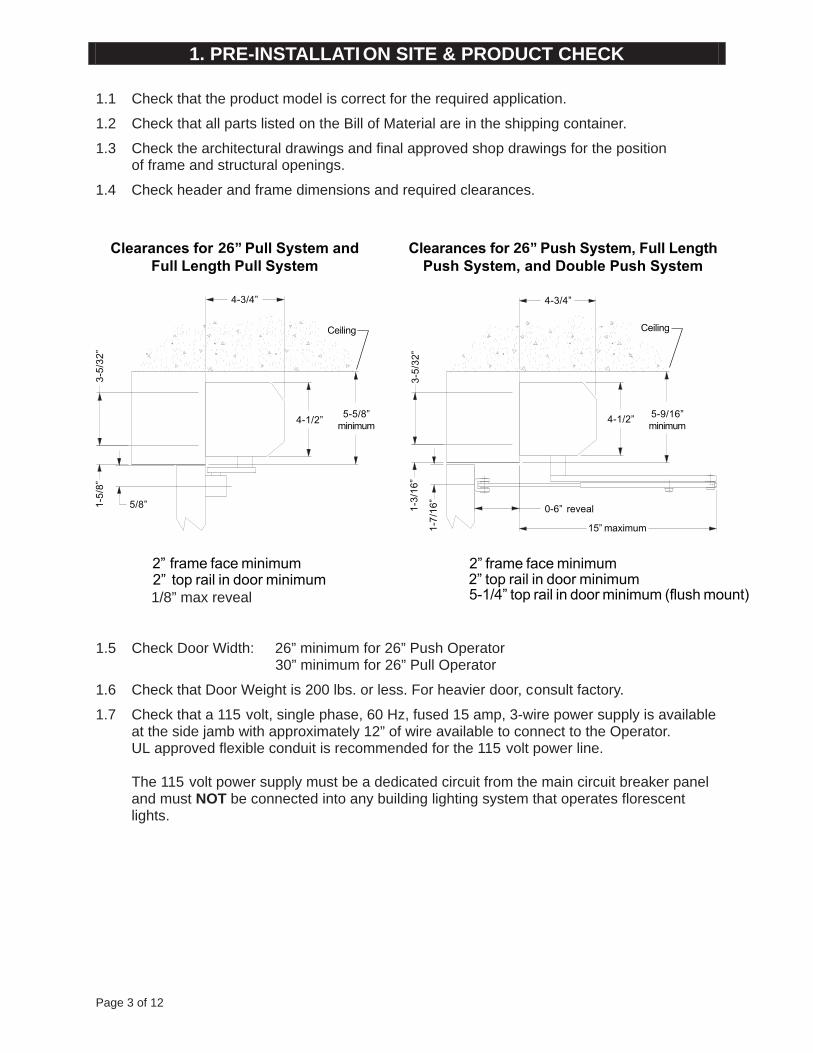
2.1 Remove Control Box from Operator Mounting Bracket, then remove Motor/Gearbox fromBracket:
1/4” - 20 Remove screw to remove controlbox from mounting bracket
2.2 Prepare Header/Frame and Door: 26” Pull System ..............................See below5egaP............................metsyShsuP”625egaP..................noitacilppAtnuoMporD
2.3 Install Operator Mounting Bracket on Header/Frame. Do not install the center screwsuntil you’ve attached the Motor Gearbox assembly in step 2.4
2.4 Install Motor/Gearbox on Operator Mounting Bracket. If there is not a mounting surfacefor both screws on the Gearbox, use the ¼”-20 nut removed in 2.1 to secure thegearbox. Then install the Control Box.
2.5 Proceed to Chapter 3: Wiring (page 6 ).
26” Pull SystemHeader/Frame and Door Preparation
6”1/5-518”/3-9
6
2. OPERATOR INSTALLATION
CAUTIONWhen mounting to an aluminumframe, the use of rivet nuts isstrongly recommended.
26” Pull, 26” Push
ControlBox
Gearbox
1-11/16”
Drill 1/2” hole in jamb tube in this area for low voltage wire access
24”
Page 5 of 12
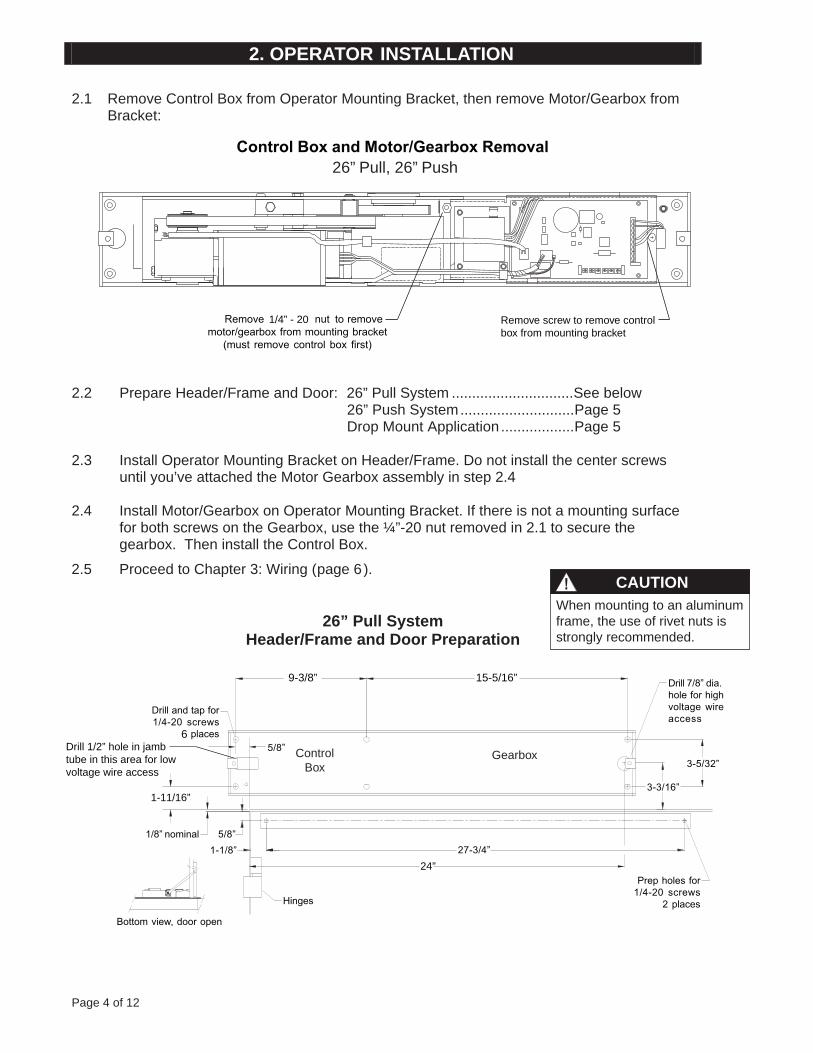
26” Push SystemHeader/Frame and Door Preparation
6”1/5-518”/3-9
Drop Mount Application (26” Push System Only)Header/Frame and Door Preparation
6”1/5-51 8”/3-9
2. OPERATOR INSTALLATION (CNTD)
ControlBox
Gearbox
6
4
1-3/16”
5/8”
Page 6 of 12
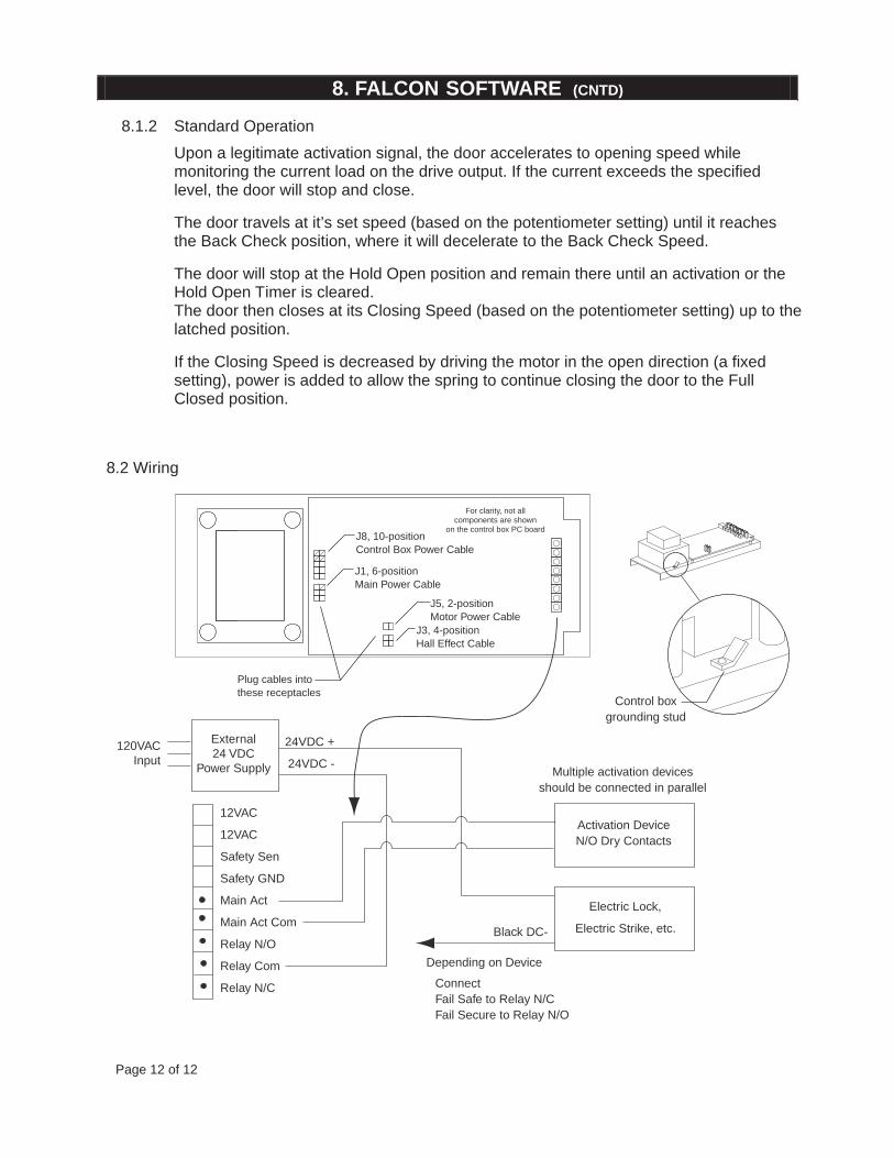
3.1 Refer to the appropriate wiring diagram for the Control Box (page 12 ) or the diagramsupplied for custom applications.Connect the following cables:
Ground Cable (Ground the Operator properly with the earth from main supply)Hall Effect Cable (Do not wrap the Hall Effect Cable around the Motor Power Cable)
Motor Power Cable (Do not wrap the Motor Power Cable around the Hall Effect Cable)
Control Box Power Cable
3.2 Connect activate and lock accessories, as needed.Refer to the accessory instructions for any accessories used.Do not connect any remote activating device to the door unless it is located withinline of sight of the door.
3.3 When wiring is complete, proceed to Chapter 4: Arm and Cover Installation (page 6 )
3. WIRING
CAUTION
Make sure all wires are properly dressed and secured to prevent interferenceRoute all wiring away from moving parts, sharp edges, and heat sourcesUse copper conductors onlyDo not modify the factory wiring or connect into existing electrical circuits or devices
WARNING
Keep hands, clothing, wires, tools, etc., AWAY FROM Operator Motorwhen the Operator Motor is turned on
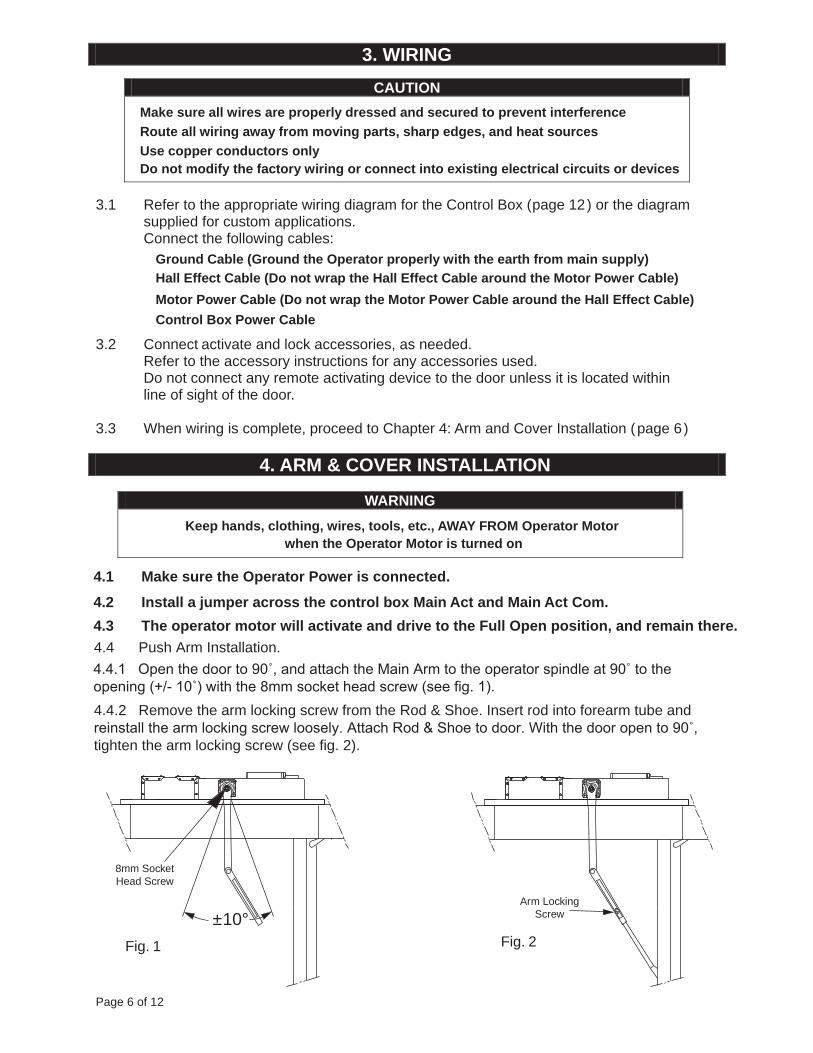
4.1 Make sure the Operator Power is connected.
4.2 Install a jumper across the control box Main Act and Main Act Com.
4.3 The operator motor will activate and drive to the Full Open position, and remain there.4.4 Push Arm Installation.
4.4.1 Open the door to 90˚, and attach the Main Arm to the operator spindle at 90˚ to theopening (+/- 10˚) with the 8mm socket head screw (see fig. 1).4.4.2 Remove the arm locking screw from the Rod & Shoe. Insert rod into forearm tube andreinstall the arm locking screw loosely. Attach Rod & Shoe to door. With the door open to 90˚,tighten the arm locking screw (see fig. 2).
4. ARM & COVER INSTALLATION
±10°Arm Locking
Screw
8mm SocketHead Screw
Fig. 1 Fig. 2
Page 7 of 12
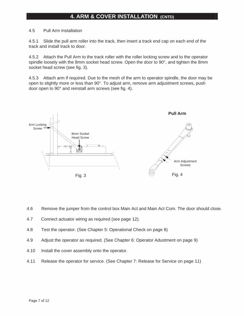
4.5 Pull Arm Installation
4.5.1 Slide the pull arm roller into the track, then insert a track end cap on each end of the track and install track to door.
4.5.2 Attach the Pull Arm to the track roller with the roller locking screw and to the operatorspindle loosely with the 8mm socket head screw. Open the door to 90°, and tighten the 8mm socket head screw (see fig. 3).
4.5.3 Attach arm if required. Due to the mesh of the arm to operator spindle, the door may be open to slightly more or less than 90°. To adjust arm, remove arm adjustment screws, pushdoor open to 90° and reinstall arm screws (see fig. 4).
4.6 Remove the jumper from the control box Main Act and Main Act Com. The door should close.
4.7 Connect actuator wiring as required (see page 12).
4.8 Test the operator. (See Chapter 5: Operational Check on page 8)
4.9 Adjust the operator as required. (See Chapter 6: Operator Adustment on page 9)
4.10 Install the cover assembly onto the operator.
4.11 Release the operator for service. (See Chapter 7: Release for Service on page 11)
Pull Arm
4. ARM & COVER INSTALLATION (CNTD)
Fig. 4Fig. 3
Arm LockingScrew
Arm AdjustmentScrews
8mm SocketHead Screw
Page 8 of 12
5.1 Activate the operator using the activation device.The operator will perform one sizing cycle.
Sizing Cycle: Occurs after power is turned on and a legitimate activation signalis received. During the sizing cycle, the door opens and closes one time.
5.2 If the door does NOT OPEN AT ALL during the sizing cycle:
• Check the door for binding.
• If an electromechanical lock is being used, check that the lock disengages before theoperator opens the door.
• Check fuses, circuit breakers and connections.
• Adjust the operator and check the door operation(See chapter 6: Operator Adjustment onBelow are default settings:
page 9)
Opening Speed 9:00Back Check Speed 3:00Hold Open Time Delay 10:00Latch Position 12:00Closing Speed 12:00Back check position 4:00 (Fully clockwise)
5.3 If the door does NOT OPEN FULLY during the sizing cycle:
• Check the door for binding.
• Increase the back check speed slightly and re-check the door operation.Repeat until door opens fully.
5.4 If the door OPENS TOO FAST during the sizing cycle, decrease the back check speedslightly and re-check the door operation. Repeat until the door opens at desired speed.
5.5 After the sizing cycle is completed and the door(s) are closed, apply a maintainedactivation signal. Check that the door remains open while the signal is applied.
5.7 When the door is operating properly, continue with Step 4.11 on page 7.
5. OPERATIONAL CHECK
Page 9 of 12
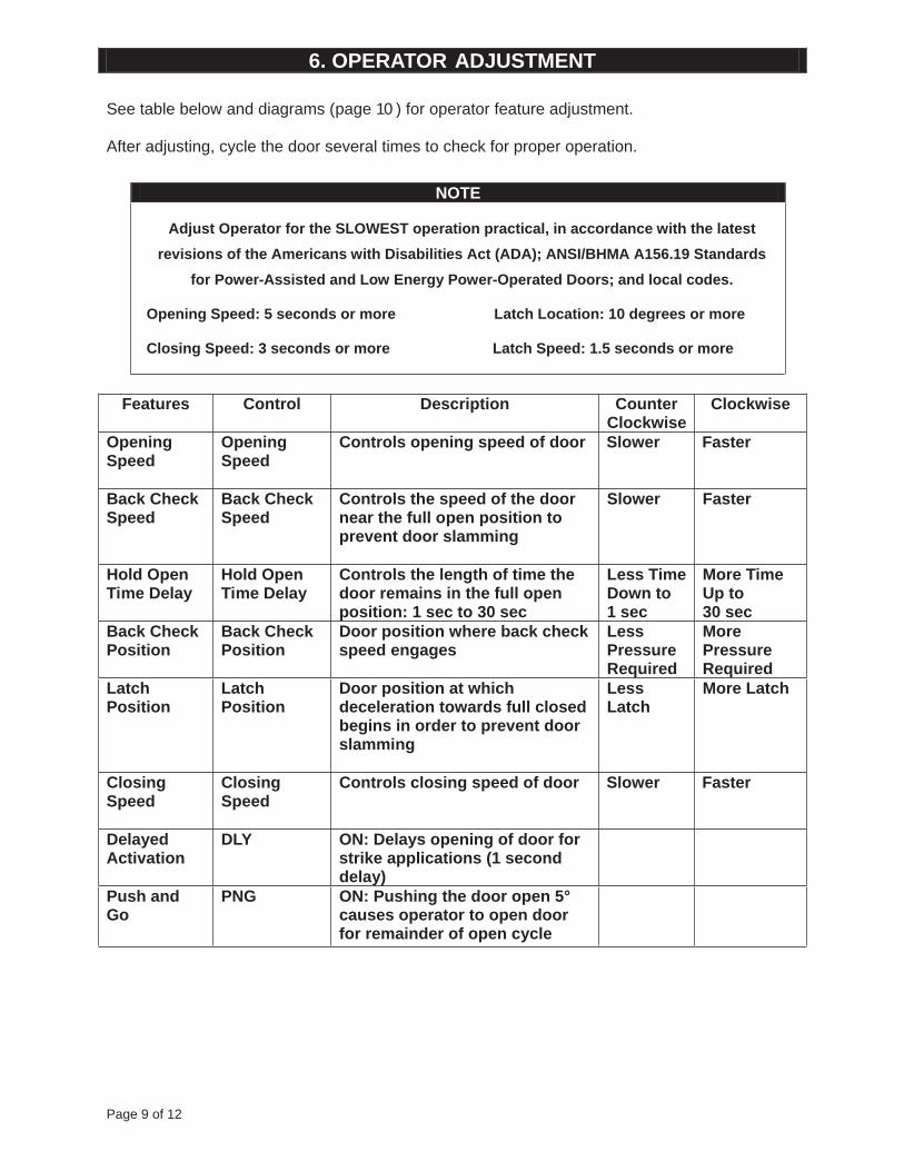
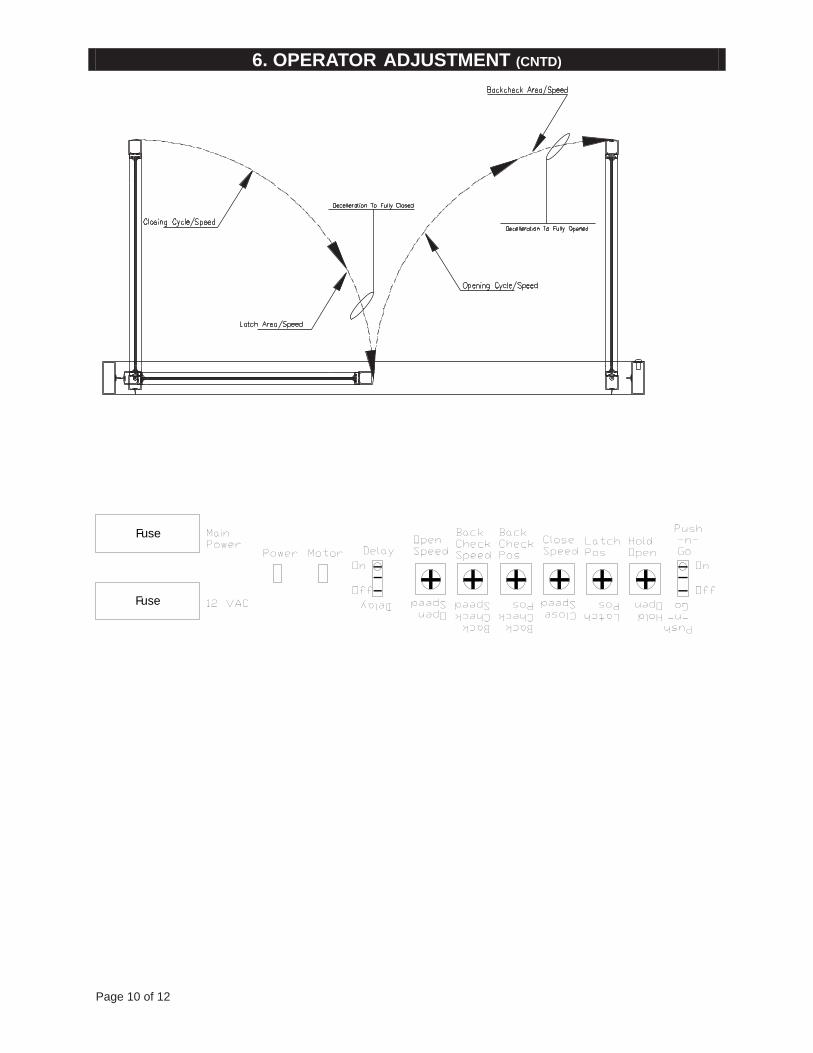
See table below and diagrams (page 10 ) for operator feature adjustment.
After adjusting, cycle the door several times to check for proper operation.
NOTE
Adjust Operator for the SLOWEST operation practical, in accordance with the latest
revisions of the Americans with Disabilities Act (ADA); ANSI/BHMA A156.19 Standards
for Power-Assisted and Low Energy Power-Operated Doors; and local codes.
Opening Speed: 5 seconds or more Latch Location: 10 degrees or more
Closing Speed: 3 seconds or more Latch Speed: 1.5 seconds or more
Features Control Description CounterClockwise
Clockwise
OpeningSpeed
OpeningSpeed
Controls opening speed of door Slower Faster
Back CheckSpeed
Back CheckSpeed
Controls the speed of the doornear the full open position toprevent door slamming
Slower Faster
Hold OpenTime Delay
Hold OpenTime Delay
Controls the length of time thedoor remains in the full openposition: 1 sec to 30 sec
Less TimeDown to1 sec
More TimeUp to30 sec
Back CheckPosition
Back CheckPosition
Door position where back checkspeed engages
LessPressureRequired
MorePressureRequired
LatchPosition
LatchPosition
Door position at whichdeceleration towards full closedbegins in order to prevent doorslamming
LessLatch
More Latch
ClosingSpeed
ClosingSpeed
Controls closing speed of door Slower Faster
DelayedActivation
DLY ON: Delays opening of door forstrike applications (1 seconddelay)
Push andGo
PNG ON: Pushing the door open 5°causes operator to open doorfor remainder of open cycle
6. OPERATOR ADJUSTMENT
Page 10 of 12
BackCheckSpeed
BackCheckSpeed
BackCheckPos
BackCheckPos
CloseSpeed
CloseSpeed
LatchPos
LatchPos
HoldOpen
HoldOpen
Push-n-Go
Push-n-Go
On
Off
OpenSpeed
OpenSpeed
Delay
Delay
On
Off
MainPower
12 VAC
Power Motor
Fuse
Fuse
6. OPERATOR ADJUSTMENT (CNTD)
Page 11 of 12
7.1 Remove all tools, installation equipment and debris from the vicinity of the door.
7.2 MANDATORY: Install all Safety, Traffic Control and Instruction Labels onto the door,as required.
Failure to do this will leave the INSTALLER LIABLE for any accidents that occur.
7.3 Give verbal instruction on how to properly operate the door to the owner orperson in charge.
7.4 Give verbal instruction to the owner or person in charge on periodic inspection of thedoor for the following:
• Occasional damage
• Developing problems
• Minor preventative maintenance
7.5 Provide the owner or person in charge with a contact name and phone number to callfor future service and maintenance.
IMPORTANT
Be sure to install all Safety, Traffic Control and Instruction Labels
onto the door, as required
7. RELEASE FOR SERVICE
8.1 Operation:
8.1.1 Sizing
From start-up (Sizing), the door will activate via:
Main Input (Main Act and Main Act Com).
The first motion of the door will be towards the Door Open position. The speed duringSizing is automatic and cannot be set from a potentiometer.
The door drives to full open and the system sets the open counter to full open.
The door closes at Closing Speed. The system sets the closed counter to Full Closedwhen the latch goes up at the Closed position.
The system calculates all other parameters required for normal operation based on thetwo values of Full Open and Full Closed.
8. FALCON SOFTWARE
Page 12 of 12
8.1.2 Standard Operation
Upon a legitimate activation signal, the door accelerates to opening speed whilemonitoring the current load on the drive output. If the current exceeds the specifiedlevel, the door will stop and close.
The door travels at it’s set speed (based on the potentiometer setting) until it reachesthe Back Check position, where it will decelerate to the Back Check Speed.
The door will stop at the Hold Open position and remain there until an activation or theHold Open Timer is cleared.The door then closes at its Closing Speed (based on the potentiometer setting) up to thelatched position.
If the Closing Speed is decreased by driving the motor in the open direction (a fixedsetting), power is added to allow the spring to continue closing the door to the FullClosed position.
8. FALCON SOFTWARE (CNTD)
8.2 Wiring
24VDC +
24VDC -
Electric Lock,
Electric Strike, etc.
Depending on Device
Black DC-
Activation DeviceN/O Dry Contacts
Multiple activation devicesshould be connected in parallel
Control boxgrounding stud
For clarity, not allcomponents are shown
on the control box PC boardJ8, 10-positionControl Box Power Cable
J1, 6-positionMain Power Cable
J5, 2-positionMotor Power Cable
J3, 4-positionHall Effect Cable
Plug cables intothese receptacles
External24 VDC
Power Supply
12VAC
12VAC
Safety Sen
Safety GND
Main Act
Main Act Com
Relay N/O
Relay Com
Relay N/C
120VACInput
ConnectFail Safe to Relay N/CFail Secure to Relay N/O


![Vol 39 - [Swing, Swing, Swing]](https://img.pdfslide.net/doc/110x75/55cf8f5a550346703b9b7709/vol-39-swing-swing-swing-5699adb3c742c.jpg)