Embed Size (px)
Citation preview

Switch (8) HDMI source devices plus IR to (8) HDMI displays.
Supports 1080p 3D HDMI or DVI formats + IR with RS-232 or IR remote control.
8 x 8 HDMI Matrix Switch
VSW-HDMI8X8-B
Order toll-free in the U.S.: Call 877-877-BBOX (outside U.S. call 724-746-5500)FREE technical support 24 hours a day, 7 days a week: Call 724-746-5500 or fax 724-746-0746Mailing address: Black Box Corporation, 1000 Park Drive, Lawrence, PA 15055-1018Web site: www.blackbox.com • E-mail: [email protected]
Customer Support
Information

724-746-5500 | blackbox.com Page 2
Trademarks Used in this Manual
We‘re here to help! If you have any questions about your application or our products, contact Black Box Tech Support at 724-746-5500
or go to blackbox.com and click on “Talk to Black Box.”You’ll be live with one of our technical experts in less than 60 seconds.
Trademarks Used in this Manual
Black Box and the Double Diamond logo are registered trademarks of BB Technologies, Inc.
Any other trademarks mentioned in this manual are acknowledged to be the property of the trademark owners.
Blu-ray is a trademark of the Blu-ray Disc Association.
HDMI is a registered trademark of HDMI Licensing L.L.C.
Xbox and Windows are registered trademarks of Microsoft Corporation.

724-746-5500 | blackbox.com Page 3
FCC and IC RFI Statements
Federal Communications Commission and Industry Canada Radio Frequency Interference Statements
This equipment generates, uses, and can radiate radio-frequency energy, and if not installed and used properly, that is, in strict accordance with the manufacturer’s instructions, may cause inter ference to radio communication. It has been tested and found to comply with the limits for a Class A computing device in accordance with the specifications in Subpart B of Part 15 of FCC rules, which are designed to provide reasonable protection against such interference when the equipment is operated in a commercial environment. Operation of this equipment in a residential area is likely to cause interference, in which case the user at his own expense will be required to take whatever measures may be necessary to correct the interference.
Changes or modifications not expressly approved by the party responsible for compliance could void the user’s authority to operate the equipment.
This digital apparatus does not exceed the Class A limits for radio noise emis sion from digital apparatus set out in the Radio Interference Regulation of Industry Canada.
Le présent appareil numérique n’émet pas de bruits radioélectriques dépassant les limites applicables aux appareils numériques de la classe A prescrites dans le Règlement sur le brouillage radioélectrique publié par Industrie Canada.
724-746-5500 | blackbox.com Page 4
NOM Statement
Instrucciones de Seguridad(Normas Oficiales Mexicanas Electrical Safety Statement)1. Todas las instrucciones de seguridad y operación deberán ser leídas antes de que el aparato eléctrico sea operado.
2. Las instrucciones de seguridad y operación deberán ser guardadas para referencia futura.
3. Todas las advertencias en el aparato eléctrico y en sus instrucciones de operación deben ser respetadas.
4. Todas las instrucciones de operación y uso deben ser seguidas.
5. El aparato eléctrico no deberá ser usado cerca del agua—por ejemplo, cerca de la tina de baño, lavabo, sótano mojado o cerca de una alberca, etc.
6. El aparato eléctrico debe ser usado únicamente con carritos o pedestales que sean recomendados por el fabricante.
7. El aparato eléctrico debe ser montado a la pared o al techo sólo como sea recomendado por el fabricante.
8. Servicio—El usuario no debe intentar dar servicio al equipo eléctrico más allá a lo descrito en las instrucciones de operación. Todo otro servicio deberá ser referido a personal de servicio calificado.
9. El aparato eléctrico debe ser situado de tal manera que su posición no interfiera su uso. La colocación del aparato eléctrico sobre una cama, sofá, alfombra o superficie similar puede bloquea la ventilación, no se debe colocar en libreros o gabinetes que impidan el flujo de aire por los orificios de ventilación.
10. El equipo eléctrico deber ser situado fuera del alcance de fuentes de calor como radiadores, registros de calor, estufas u otros aparatos (incluyendo amplificadores) que producen calor.
11. El aparato eléctrico deberá ser connectado a una fuente de poder sólo del tipo descrito en el instructivo de operación, o como se indique en el aparato.
12. Precaución debe ser tomada de tal manera que la tierra fisica y la polarización del equipo no sea eliminada.
13. Los cables de la fuente de poder deben ser guiados de tal manera que no sean pisados ni pellizcados por objetos colocados sobre o contra ellos, poniendo particular atención a los contactos y receptáculos donde salen del aparato.
14. El equipo eléctrico debe ser limpiado únicamente de acuerdo a las recomendaciones del fabricante.
15. En caso de existir, una antena externa deberá ser localizada lejos de las lineas de energia.
16. El cable de corriente deberá ser desconectado del cuando el equipo no sea usado por un largo periodo de tiempo.
17. Cuidado debe ser tomado de tal manera que objectos liquidos no sean derramados sobre la cubierta u orificios de ventilación.
18. Servicio por personal calificado deberá ser provisto cuando: A: El cable de poder o el contacto ha sido dañado; u B: Objectos han caído o líquido ha sido derramado dentro del aparato; o C: El aparato ha sido expuesto a la lluvia; o D: El aparato parece no operar normalmente o muestra un cambio en su desempeño; o E: El aparato ha sido tirado o su cubierta ha sido dañada.

724-746-5500 | blackbox.com Page 5
Safety Information
Safety Information
NOTE: THIS SAFETY INFORMATION IS OF A GENERAL NATURE AND MAY BE SUPERSEDED BY INSTRUCTIONS CONTAINED WITHIN THIS MANUAL.
1. Save the carton and packing material even if the equipment has arrived in good condition. If you ever need to ship the unit, use only the original factory packing.
2. Read all documentation before operating your equipment. Retain all documentation for future reference.
3. Follow all instructions printed on unit chassis for proper operation.
4. Do not spill water or other liquids into or on the unit, or operate the unit while standing in liquid.
5. Make sure power outlets conform to the power requirements listed on the back of the unit.
6. Do not use the unit if the electrical power cord is frayed or broken. The power supply cords should be routed so that they are not likely to be walked on or pinched by items placed upon or against them, paying particular attention to cords and plugs, convenience receptacles, and the point where they exit.
7. Always operate the unit with the AC ground wire connected to the electrical system ground. Precautions should be taken so that the means of grounding of a piece of equipment is not defeated.
8. Voltage must be correct and the same as that printed on the rear of the unit. Damage caused by connection to improper AC voltage is not covered by any warranty.
9. Power down and disconnect the unit from mains voltage before making connections.
10. Never hold a power switch in the “ON” position.
11. Do not use the unit near stoves, heat registers, radiators, or other heat-producing devices.
12. Do not block fan intake or exhaust ports. Do not operate equipment on a surface or in an environment which may impede the normal flow of air around the unit, such as a bed, rug, carpet, or completely enclosed rack. If the unit is used in an extremely dusty or smoky environment, the unit should be periodically “blown free” of foreign matter.
13. Do not remove the cover. Removing the cover will expose you to potentially dangerous voltages. There are no user serviceable parts inside.
14. Do not drive the inputs with a signal level greater than that required to drive equipment to full output.
15. Non-use periods. The power cord of equipment should be unplugged from the outlet when left unused for a long period of time.
16. Service information equipment should be serviced by qualifier service personnel when:
A. The power supply cord or the plug has been damaged.
B. Objects have fallen, or liquid has been spilled into the equipment.
C. The equipment has been exposed to rain.
D. The equipment does not appear to operate normally, or exhibits a marked change in performance
E. The equipment has been dropped, or the enclosure damaged.

724-746-5500 | blackbox.com Page 6
Important Safety Instructions
IMPORTANT SAFETY INSTRUCTIONSTo get the best from this product, please read this manual carefully. Keep it in a safe place for future reference.
To reduce the risk of electric shock, do not remove the cover from the unit. No user serviceable parts inside. Refer servicing to qualified personnel.
To reduce the risk of fire, do not expose the unit to rain, water or excessive moisture.
Do not force switched or external connections.
When moving the unit disconnect the serial port connections first then the power cable and finally the interconnecting cables to other devices.
Do not attempt to clean the unit with chemical solvents or aerosol cleaners, as this may damage the unit. Use a clean dry cloth.
Installation of this unit should be in a cool dry place, away from sources of excessive heat, vibration, dust, moisture and cold.
WARNING: To prevent electric shock do not use this (polarized) plug with an extension cord, receptacle or other outlet unless the blades can be fully inserted to prevent blade exposure. To prevent electric shock, match wide blade of plug to wide slot, fully insert.
CAUTION: TO REDUCE THE RISK OF ELECTRIC SHOCK, DO NOT REMOVE COVER (OR BACK), NO USER SERVICEABLE PARTS INSIDE, REFER SERVICING TO QUALIFIED SERVICE PERSONNEL.
WARNING: TO REDUCE THE RISK OF FIRE OR ELECTRIC SHOCK, DO NOT EXPOSE THIS EQUIPMENT TO RAIN OR MOISTURE.

724-746-5500 | blackbox.com Page 7
Table of Contents
Table of Contents
1. Specifications .........................................................................................................................................................................8
2. Overview ...............................................................................................................................................................................9 2.1 Introduction ...................................................................................................................................................................9 2.2 Features .........................................................................................................................................................................9 2.3 What’s Included ............................................................................................................................................................9 2.4 Hardware Description ..................................................................................................................................................10 2.4.1 Front Panel ........................................................................................................................................................10 2.4.2 Rear Panel ......................................................................................................................................................... 11
3. Installation ........................................................................................................................................................................... 13 3.1 Installation Diagram .................................................................................................................................................... 13 3.2 IR Extender ..................................................................................................................................................................14
4. Operation ............................................................................................................................................................................ 15 4.1 EDID Setup .................................................................................................................................................................. 15 4.2 Embedded EDID Modes .............................................................................................................................................. 15 4.3 Copy EDID ................................................................................................................................................................... 15 4.4 EDID Status ..................................................................................................................................................................16 4.5 How to Set Up Fast Speed Start (FSS) Function ........................................................................................................... 17 4.6 Auto Mode Definition ................................................................................................................................................. 17 4.7 Consumer Electronics Control (CEC) Setup.................................................................................................................. 17 4.8 Front-Panel Control Functions .....................................................................................................................................18 4.9 Remote Control ...........................................................................................................................................................18 4.10 IR Remote Custom and Data Codes (NEC Standard) ...................................................................................................19
5. RS-232 Serial Interface .........................................................................................................................................................20
6. Troubleshooting ...................................................................................................................................................................21 6.1 Contacting Black Box...................................................................................................................................................21 6.2 Shipping and Packaging ..............................................................................................................................................21
724-746-5500 | blackbox.com Page 8
Chapter 1: Specifications
1. Specifications
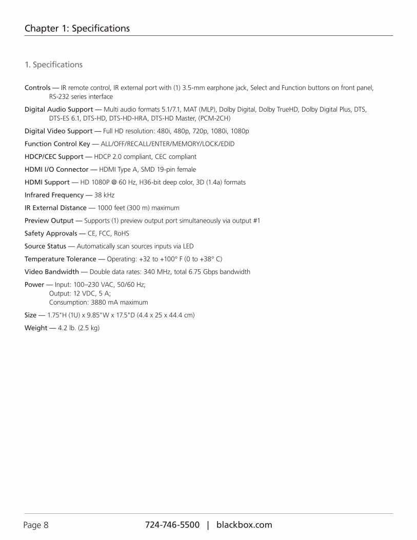
Controls — IR remote control, IR external port with (1) 3.5-mm earphone jack, Select and Function buttons on front panel, RS-232 series interface
Digital Audio Support — Multi audio formats 5.1/7.1, MAT (MLP), Dolby Digital, Dolby TrueHD, Dolby Digital Plus, DTS, DTS-ES 6.1, DTS-HD, DTS-HD-HRA, DTS-HD Master, (PCM-2CH)
Digital Video Support — Full HD resolution: 480i, 480p, 720p, 1080i, 1080p
Function Control Key — ALL/OFF/RECALL/ENTER/MEMORY/LOCK/EDID
HDCP/CEC Support — HDCP 2.0 compliant, CEC compliant
HDMI I/O Connector — HDMI Type A, SMD 19-pin female
HDMI Support — HD 1080P @ 60 Hz, H36-bit deep color, 3D (1.4a) formats
Infrared Frequency — 38 kHz
IR External Distance — 1000 feet (300 m) maximum
Preview Output — Supports (1) preview output port simultaneously via output #1
Safety Approvals — CE, FCC, RoHS
Source Status — Automatically scan sources inputs via LED
Temperature Tolerance — Operating: +32 to +100° F (0 to +38° C)
Video Bandwidth — Double data rates: 340 MHz, total 6.75 Gbps bandwidth
Power — Input: 100–230 VAC, 50/60 Hz; Output: 12 VDC, 5 A; Consumption: 3880 mA maximum
Size — 1.75"H (1U) x 9.85"W x 17.5"D (4.4 x 25 x 44.4 cm)
Weight — 4.2 lb. (2.5 kg)

724-746-5500 | blackbox.com Page 9
Chapter 2: Overview
2. Overview
2.1 IntroductionThe HDMI8X8 is a high-performance 8x8 matrix routing switch for HDMI signals. This switch supports data rates up to 6.75 Gbps, enabling 1080p HDMI formats and UXGA/WUXGA/DVI resolution to any HD display. High Definition Digital signals can be selected and distributed to any eight outputs simultaneously. The switch is certified as being fully HDMI® and HDCP compliant, with RoHS, CE, and FCC certification. It supports high-resolution HDMI sources routed to HDMI displays, monitors, projectors, or audio receivers. The EDID can be selected between seven different modes or copied from the attached displays. You can control the switch via front panel push buttons, IR remote, or RS-232.
2.2 Features• Matrix switches (8) HDMI digital source devices to (8) HDMI devices.
• Supports HDMI digital video w/embedded audio, DVI format and complies with CEC/HDCP 2.0.
• Includes (7) function key controls.
• Supports worldwide EDID modes for HDTV resolutions.
• Enables link speeds of up to 6.75 Gbps (link clock rate of 340Mb Hz) and supports HDMI 1.4a 3D formats.
• Works with wide range of HD resolutions from PC XGA to WUXGA 1920x1200 and HDTV/DTV resolutions 480i/480p, 576i/576p, 720p, 1080i, and 1080p.
• Compatible with all HDMI source devices, PC monitors, plasma HD displays, HDTV and audio receivers/amplifiers.
• Provides digital video TMDS formats resolution up to 1080P-60 with Deep color 36-bit.
• Supports digital audio: Dolby TrueHD, Dolby Digital, Dolby Digital Plug/ex, DTS, DTS-HD, DTS-HD Master, DTS-EX, PCM, PCM2, LPCM2.
• Choose from three ways to control the user interface: front panel push button, IR wireless remote control, and third-party RS-232 controller (via simple ASCII).
• Supports world wide control functions: ALL/OFF/RECALL/ENTER/MEMORY/EDID/LOCK.
• Supports built-in EDID modes, external copy, and auto mode
• Front-panel LEDs show active input and output status.
• Supports preview output port simultaneously with output #1.
• Supports IR Remote and IR Extender with distance up to 1000 feet (300 m) maximum.
• Provides EDID configuration via Internal modes.
• Consumer Electronic Control (CEC) switch can be all open or OFF.
• Remembers the last state during a power cycle.
• When power is removed and resorted, the last configuration will be restored.
2.3 What’s IncludedYour package should include the following items. If anything is missing or damaged, contact Black Box Technical Support at 724-746-5500 or [email protected].
• Main console unit
• IR remote control
• IR extender receiver kit
724-746-5500 | blackbox.com Page 10
Chapter 2: Overview
• RS-232 cable
• 100–230 VAC, 12 VDC, 5A universal power supply
• Rackmount brackets
• User manual
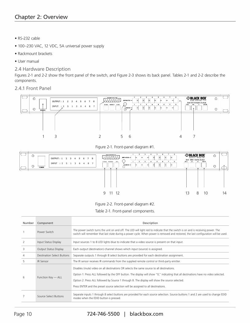
2.4 Hardware DescriptionFigures 2-1 and 2-2 show the front panel of the switch, and Figure 2-3 shows its back panel. Tables 2-1 and 2-2 describe the components.
2.4.1 Front Panel
1 3 2 5 6 4 7
Figure 2-1. Front-panel diagram #1.
9 11 12 13 8 10 14
Figure 2-2. Front-panel diagram #2.
Table 2-1. Front-panel components.
Number Component Description
1 Power SwitchThe power switch turns the unit on and off. The LED will light red to indicate that the switch is on and is receiving power. The switch will remember that last state during a power cycle. When power is removed and restored, the last configuration will be used.
2 Input Status Display Input sources 1 to 8 LED lights blue to indicate that a video source is present on that input.
3 Output Status Display Each output (destination) channel shows which input (source) is assigned.
4 Destination Select Buttons Separate outputs 1 through 8 select buttons are provided for each destination assignment.
5 IR Sensor The IR sensor receives IR commands from the supplied remote control or third-party emitter.
6 Function Key — ALL
Disables (mute) video on all destinations OR selects the same source to all destinations.
Option 1: Press ALL followed by the OFF button. The display will show “0,” indicating that all destinations have no video selected.
Option 2: Press ALL followed by Source 1 through 8. The display will show the source selected.
Press ENTER and the preset source selection will be assigned to all destinations.
7 Source Select ButtonsSeparate inputs 1 through 8 select buttons are provided for each source selection. Source buttons 1 and 2 are used to change EDID modes when the EDID button is pressed.
724-746-5500 | blackbox.com Page 11
Chapter 2: Overview
Table 2-1 (Continued). Front-panel components.
Number Component Description
8 Function Key — OFF
Disables (mutes) video to selected channels. • Press the OFF button followed by any destination channel. • Press button 1 through 4 to select the output destination. The display will show “0” for the selected channel indicating no video
selected.
9Function Key — RECALL (preview)
The system will show previously stored presets, up to a total of 16. Presets are stored in local memory using Source keys 1 through 8 or Destination keys 1 through 8 as the memory preset location. • Press the RECALL button. • Press 1 through 4 on either Source or Destination row. • Press ENTER. The preset configuration will execute. Operation completes.
NOTE: Operation will abort if no keys are pressed within 5 seconds.
10Function Key—Enter (or DEMO)
Press ENTER to confirm entries.
11Function Key—Memory (or SAVE)
The system will store presets, up to a total of 16. Presets are stored in local memory using Source keys 1 through 8 or Destination keys 1 through 8 as the memory preset location. • Configure desired matrices. • Press the memory button. • Press 1 through 4 on either Source or Destination row. • Press ENTER to ready memory location. • Or press MEMORY again to cancel operation. Operation completes.
NOTE: Operation will abort if no keys are pressed within 5 seconds.
12 Function Key — LOCK• Press and hold the LOCK button for two seconds to lockout the front panel. • Press and hold the LOCK button for two seconds to re-enable the front panel.
13 Function Key — EDID Press EDID to select new EDID mode and select source button #1 or #2 to change embedded EDID mode.
14 19" rackmount ears Converts a desktop switch to a 19-inch rackmount switch. Brackets are included. Figure 2-2 shows rackmount bracket attached.
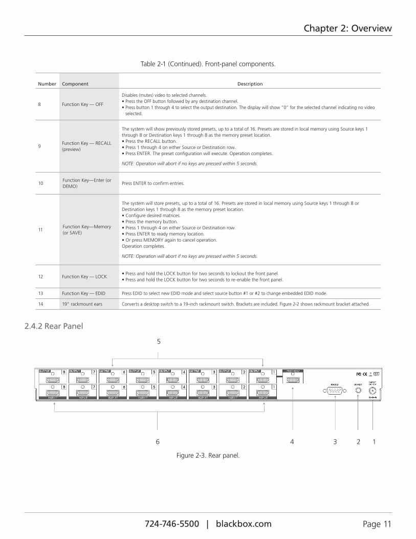
2.4.2 Rear Panel
6 4 3 2 1
5
Figure 2-3. Rear panel.
724-746-5500 | blackbox.com Page 12
Chapter 2: Overview
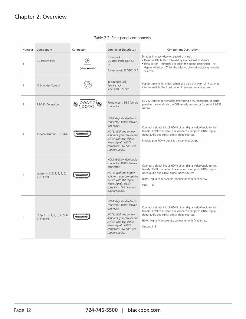
Table 2-2. Rear-panel components.
Number Component Connector Connector Descripton Component Description
1DC Power Inlet
Power jack: DC jack: inner OID 2.1-mm
Power input: 12 VDC, 5 A
Disables (mutes) video to selected channels. • Press the OFF button followed by any destination channel. • Press button 1 through 4 to select the output destination. The
display will show “0” for the selected channel indicating no video selected.
2 IR Extender ControlIR extender jack: Female jack: inner OID 3.5-mm
Support one IR Extender. When you plug the external IR extender into the switch, the front panel IR receiver remains active.
3 RS-232 ConnectionRemote port: DB9 female connector
RS-232 control port enables interfacing a PC, computer, or touch panel to the switch via the DB9 female connector for serial RS-232 control.
4 Preview Output-01 HDMI
HDMI digital video/audio connector: HDMI female connector.
NOTE: With the proper adapters, you can use the switch with DVI digital video signals. HDCP compliant. DVI does not support audio.
Connect a signal link of HDMI direct digital video/audio to this female HDMI connector. The connector supports HDMI digital video/audio and HDMI digital video sources.
Preview port HDMI signal is the same as Output 1.
5Inputs — 1, 2, 3, 4, 5, 6, 7, 8 HDMI
HDMI digital video/audio connector: HDMI female connector.
NOTE: With the proper adapters, you can use the switch with DVI digital video signals. HDCP compliant. DVI does not support audio.
Connect a signal link of HDMI direct digital video/audio to this female HDMI connector. The connector supports HDMI digital video/audio and HDMI digital video sources.
HDMI Digital Video/Audio, connector with fixed screw
Input 1–8
6Outputs — 1, 2, 3, 4, 5, 6, 7, 8 HDMI
HDMI digital video/audio connector: HDMI female connector.
NOTE: With the proper adapters, you can use the switch with DVI digital video signals. HDCP compliant. DVI does not support audio.
Connect a signal link of HDMI direct digital video/audio to this female HDMI connector. The connector supports HDMI digital video/audio and HDMI digital videp sources.
HDMI Digital Video/Audio, connector with fixed screw
Output 1–8
724-746-5500 | blackbox.com Page 13
Chapter 3: Installation
3. Installation
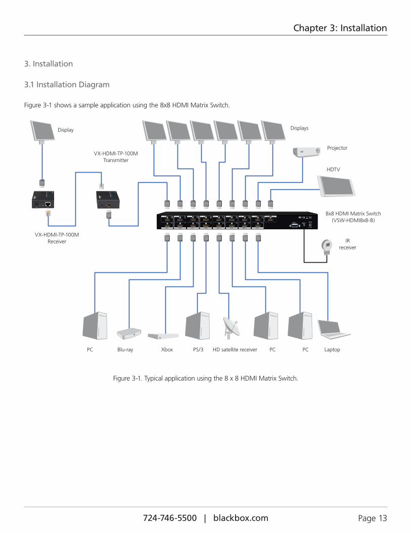
3.1 Installation Diagram
Figure 3-1 shows a sample application using the 8x8 HDMI Matrix Switch.
PC Blu-ray Xbox PS/3 HD satellite receiver PC PC Laptop
8x8 HDMI Matrix Switch (VSW-HDMI8x8-B)
Displays
Projector
HDTV
IR receiver
VX-HDMI-TP-100M Transmitter
VX-HDMI-TP-100M Receiver
Display
Figure 3-1. Typical application using the 8 x 8 HDMI Matrix Switch.

724-746-5500 | blackbox.com Page 14
Chapter 3: Installation
3.2 IR Extender
Figure 3-2. IR extender connection.
NOTE: When you plug the external IR extender into the switch, the front panel IR receiver remains active.
STEP 1
STEP 2 STEP 3
Figure 3-3. How to set up the IR extender components: Steps 1-3.
724-746-5500 | blackbox.com Page 15
Chapter 4: Operation
4. Operation
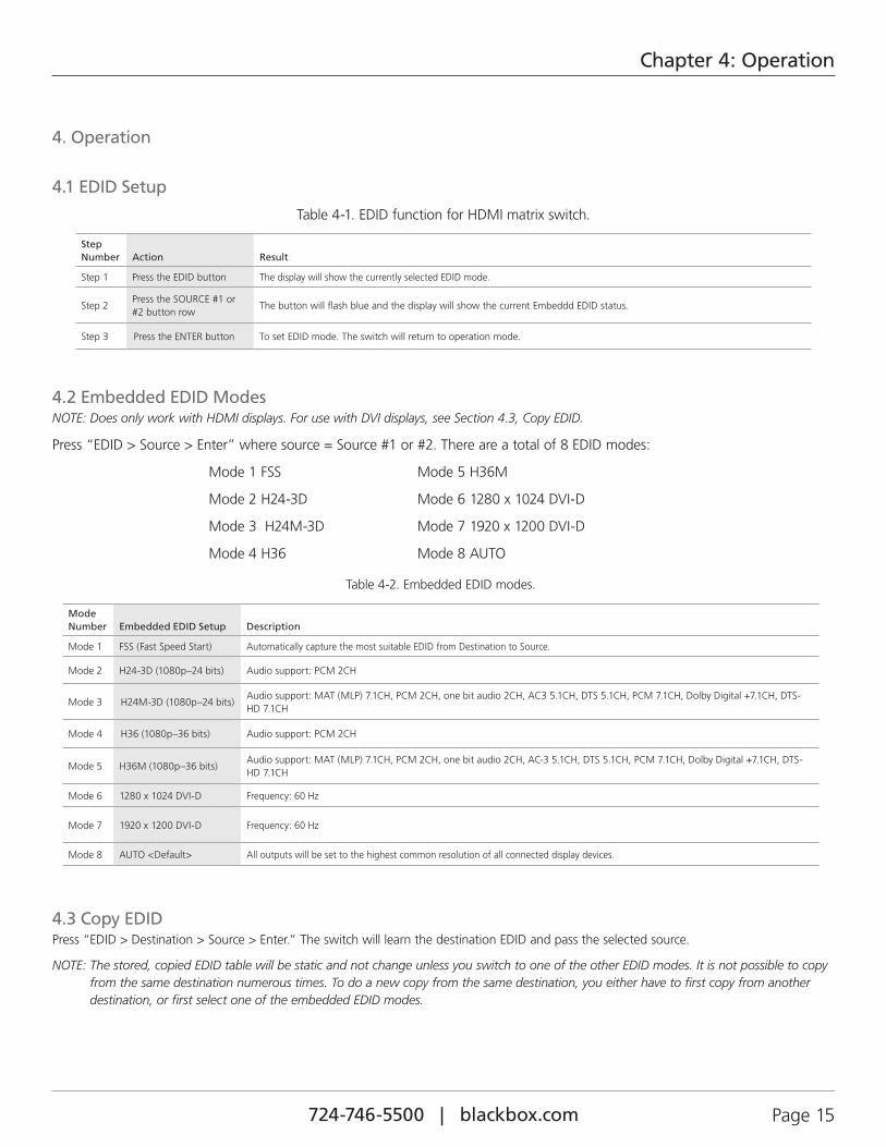
4.1 EDID Setup
Table 4-1. EDID function for HDMI matrix switch.
Step Number Action Result
Step 1 Press the EDID button The display will show the currently selected EDID mode.
Step 2Press the SOURCE #1 or #2 button row
The button will flash blue and the display will show the current Embeddd EDID status.
Step 3 Press the ENTER button To set EDID mode. The switch will return to operation mode.
4.2 Embedded EDID ModesNOTE: Does only work with HDMI displays. For use with DVI displays, see Section 4.3, Copy EDID.
Press “EDID > Source > Enter” where source = Source #1 or #2. There are a total of 8 EDID modes:
Mode 1 FSS Mode 5 H36M
Mode 2 H24-3D Mode 6 1280 x 1024 DVI-D
Mode 3 H24M-3D Mode 7 1920 x 1200 DVI-D
Mode 4 H36 Mode 8 AUTO
Table 4-2. Embedded EDID modes.
Mode Number Embedded EDID Setup Description
Mode 1 FSS (Fast Speed Start) Automatically capture the most suitable EDID from Destination to Source.
Mode 2 H24-3D (1080p–24 bits) Audio support: PCM 2CH
Mode 3 H24M-3D (1080p–24 bits)Audio support: MAT (MLP) 7.1CH, PCM 2CH, one bit audio 2CH, AC3 5.1CH, DTS 5.1CH, PCM 7.1CH, Dolby Digital +7.1CH, DTS-HD 7.1CH
Mode 4 H36 (1080p–36 bits) Audio support: PCM 2CH
Mode 5 H36M (1080p–36 bits)Audio support: MAT (MLP) 7.1CH, PCM 2CH, one bit audio 2CH, AC-3 5.1CH, DTS 5.1CH, PCM 7.1CH, Dolby Digital +7.1CH, DTS-HD 7.1CH
Mode 6 1280 x 1024 DVI-D Frequency: 60 Hz
Mode 7 1920 x 1200 DVI-D Frequency: 60 Hz
Mode 8 AUTO <Default> All outputs will be set to the highest common resolution of all connected display devices.
4.3 Copy EDIDPress “EDID > Destination > Source > Enter.” The switch will learn the destination EDID and pass the selected source.
NOTE: The stored, copied EDID table will be static and not change unless you switch to one of the other EDID modes. It is not possible to copy from the same destination numerous times. To do a new copy from the same destination, you either have to first copy from another destination, or first select one of the embedded EDID modes.
724-746-5500 | blackbox.com Page 16
Chapter 4: Operation
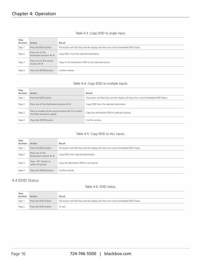
Table 4-3. Copy EDID to single input.
Step Number Action Result
Step 1 Press the EDID button The button will flash blue and the display will show the current Embedded EDID Status.
Step 2Press one of the Destination buttons #1-8
Copy EDID. from the selected destination.
Step 3Press one of the source buttons #1-8
Copy to the Destination EDID to the selected source.
Step 4 Press the ENTER button Confirm entries.
Table 4-4. Copy EDID to multiple inputs.
Step Number Action Result
Step 1 Press the EDID button The button will flash blue and the display will show the current Embedded EDID Status.
Step 2 Press one of the Destination buttons #1-8 Copy EDID from the selected destination.
Step 3Press to enable all the source buttons (#1-5) to which the EDID should be copied.
Copy the destination EDID to selected sources.
Step 4 Press the ENTER button Confirm entries.
Table 4-5. Copy EDID to ALL inputs.
Step Number Action Result
Step 1 Press the EDID button The button will flash blue and the display will show the current Embedded EDID Status.
Step 2Press one of the Destination buttons #1-8
Copy EDID from selected destination.
Step 3Press "All" button to select all sources
Copy the destination EDID to all sources.
Step 4 Press the ENTER button Confirm entries.
4.4 EDID Status
Table 4-6. EDID status.
Step Number Action Result
Step 1 Press the EDID button The button will flash blue and the display will show the current Embedded EDID Status.
Step 2 Press the EDID button To exit.

724-746-5500 | blackbox.com Page 17
Chapter 4: Operation
4.5 How to Set Up Fast Speed Start (FSS) FunctionTable 4-7. Setting up Fast Speed Start (FSS) function.
Step Number Action Result
Step 1 Press the Destination #1–8 button row, then press the Source #1–8 button row To set up and install all devices.
Step 2 Press EDID button Select an optimum status of Embedded EDID mode.
Step 3 Press the ENTER button Confirm entries.
Step 4 Press the EDID button Select the EDID FSS mode.
Step 5 Press the ENTER button Confirm entries.
4.6 Auto Mode DefinitionThe switch will detect and automatically copy the EDID for the highest common supported video mode of the displays.
Example for a single destination:
Destination device #1 will be set to the highest common audio and video mode supported by source #1.
Example for multiple destinations:
The highest supported common audio and video mode for destination device #1, #2 and #3 will be copied to the active source.
4.7 Consumer Electronics Control (CEC) SetupIn brief, CEC allows HDMI devices to control each other when necessary and allows the user to operate multiple devices with one remote control handset.
To enable CEC:
• Press EDID button.
• Press ALL button.
• Press EDID button. The pre-set configuration will execute.
To disable CEC:
• Press EDID button
• Press OFF button
• Press EDID button The pre-set configuration will execute.
NOTE: Not all devices support CEC. Check with your device’s Users Guide for additional information and specifications. For stable operation, only connect HDMI connections with the switch powered OFF.
724-746-5500 | blackbox.com Page 18
Chapter 4: Operation
4.8 Front-Panel Control FunctionsSee Chapter 2.
4.9 Remote ControlBefore making any connections to the switch, observe the following:
• Make sure that the voltage supply matches the label on the supplied plug (±10%).
• Make sure that the power switch is OFF.
• Make sure that all system grounds are connected to a common point.
• Avoid powering equipment with a system from multiple power sources that may be separated by large distances.
• Connect all audio video sources and destination equipment.
• Power on all source and destination audio-visual sources.
• For each destination output, select the appropriate input source by using the front-panel input 1–8 select buttons, the supplied IR remote control, or through the RS-232 serial communications port.
• Upon power up the switch will return to its last used setting before it was powered down.
POWER
ON OFF
DESTINATION
SOURCES
1 2 3 4
5 6 7 8
1 2 3 4
5 6 7 8
ALL OFF EDID
LOCK RECALL MEMORY ENTER
8x8 HDMI MATRIX SWITCH
1 2
5
4
3
Figure 4-1. IR remote.
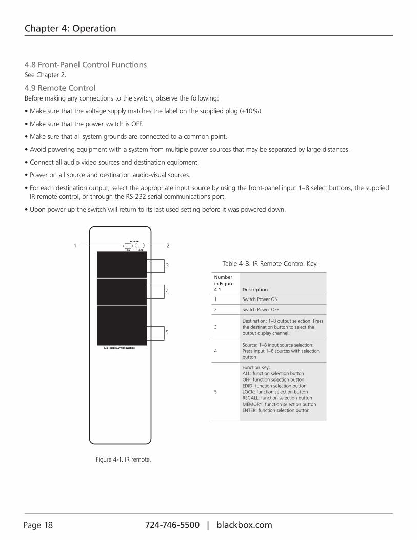
Table 4-8. IR Remote Control Key.
Number in Figure 4-1 Description
1 Switch Power ON
2 Switch Power OFF
3Destination: 1–8 output selection: Press the destination button to select the output display channel.
4Source: 1–8 input source selection: Press input 1–8 sources with selection button
5
Function Key: ALL: function selection button OFF: function selection button EDID: function selection button LOCK: function selection button RECALL: function selection button MEMORY: function selection button ENTER: function selection button

724-746-5500 | blackbox.com Page 19
Chapter 4: Operation
4.10 IR Remote Custom and Data Codes (NEC Standard)
HOW TO SETUP IR CODES:
CUSTOM CODE: 09F6 ALL: 09F6 B04F
POWER ON: 09F6 A15E ENTER: 09F6 B34C
POWER OFF: 09F6 A25D EDID: 09F6 B748
LOCK: 09F6 B54A
PRESS DESTINATION # then PRESS SOURCE #
DESTINATION #1: 09F6 10EF SOURCE #1 : 09F6 01FE DESTINATION #2: 09F6 20DF SOURCE #2 : 09F6 02FD DESTINATION #3: 09F6 30CF SOURCE #3 : 09F6 03FC DESTINATION #4: 09F6 40BF SOURCE #4 : 09F6 04FB DESTINATION #5: 09F6 50AF SOURCE #5 : 09F6 05FA DESTINATION #6: 09F6 609F SOURCE #6 : 09F6 06F9 DESTINATION #7: 09F6 708F SOURCE #7 : 09F6 07F8 DESTINATION #8: 09F6 807F SOURCE #8 : 09F6 08F7
For example:
Select Destination # 1 to show Source #1~8,
The IR Data Code list:
Press Destination #1, Source #1 009F6 10EF 09F6 01FE Press Destination #1, Source #2 09F6 10EF 09F6 02FD Press Destination #1, Source #3 09F6 10EF 09F6 03FC Press Destination #1, Source #4 09F6 10EF 09F6 04FB Press Destination #1, Source #5 09F6 10EF 09F6 05FA Press Destination #1, Source #6 09F6 10EF 09F6 06F9 Press Destination #1, Source #7 09F6 10EF 09F6 07F8 Press Destination #1, Source #8 09F6 10EF 09F6 08F7
724-746-5500 | blackbox.com Page 20
Chapter 5: RS-232 Serial Interface
5. RS-232 Serial Interface
RS-232 SERIAL INTERFACE CONNECT A PC OR CONTROL SYSTEM. VERSION COMPATIBLE V2.0
For a complete list of commands, refer to the extended RS-232 Protocol Instruction Manual.
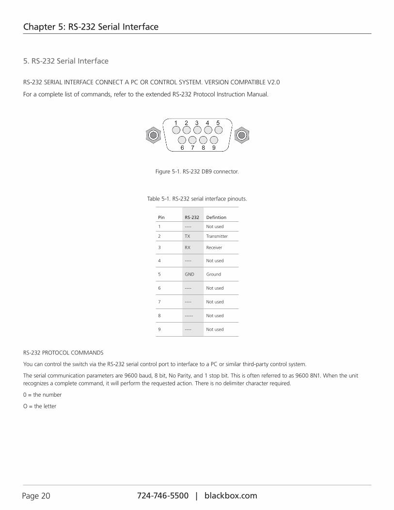
Figure 5-1. RS-232 DB9 connector.
Table 5-1. RS-232 serial interface pinouts.
Pin RS-232 Defintion
1 ---- Not used
2 TX Transmitter
3 RX Receiver
4 ---- Not used
5 GND Ground
6 ---- Not used
7 ---- Not used
8 ----- Not used
9 ---- Not used
RS-232 PROTOCOL COMMANDS
You can control the switch via the RS-232 serial control port to interface to a PC or similar third-party control system.
The serial communication parameters are 9600 baud, 8 bit, No Parity, and 1 stop bit. This is often referred to as 9600 8N1. When the unit recognizes a complete command, it will perform the requested action. There is no delimiter character required.
0 = the number
O = the letter
724-746-5500 | blackbox.com Page 21
Chapter 6: Troubleshooting
6. Troubleshooting
6.1 Contacting Black BoxIf you determine that your 8X8 HDMI Matrix Switch is malfunctioning, do not attempt to alter or repair the unit. It contains no user-serviceable parts. Contact Black Box Technical Support at 724-746-5500 or [email protected].
Before you do, make a record of the history of the problem. We will be able to provide more efficient and accurate assistance if you have a complete description, including:
• the nature and duration of the problem.
• when the problem occurs.
• the components involved in the problem.
• any particular application that, when used, appears to create the problem or make it worse.
6.2 Shipping and PackagingIf you need to transport or ship your 8X8 HDMI Matrix Switch:
• Package it carefully. We recommend that you use the original container.
• If you are returning the unit, make sure you include everything you received with it. Before you ship for return or repair, contact Black Box to get a Return Authorization (RA) number.

724-746-5500 | blackbox.com Page 22
NOTES

724-746-5500 | blackbox.com Page 23
NOTES

724-746-5500 | blackbox.com
About Black BoxBlack Box provides an extensive range of networking and infrastructure products. You’ll find everything from cabinets and racks and power and surge protection products to media converters and Ethernet switches all supported by free, live 24/7 Tech support available in 60 seconds or less.
© Copyright 2016. Black Box Corporation. All rights reserved.
Black Box Tech Support: FREE! Live. 24/7.
Tech support the way it should be.
Great tech support is just 60 seconds away at 724-746-5500 or blackbox.com.
VSW-HDMI8X8-B, version 4