Embed Size (px)
Citation preview
Oiltight Switches and Pilot Devices TW Series: 22mm
www.idec.com USA: (800) 262-IDEC or (408) 747-0550, Canada (888) 317-IDEC A-121
A
Sw
itch
es &
Pilo
t Devic
es
TW NEMA Style Switches with snap-on contacts
TW Series — 22mm NEMA Style Pushbuttons
Key features include:
• Corrosion resistant octagonal chrome plated locking bezel
• Snap-on 10A contact blocks • Transformer or full voltage• Incandescent or LED illumination • Slow make, double break, self cleaning contacts •Modular construction for maximum flexibility•NEMA 4X and IP65 watertight/oiltight panel•Available assembled or as sub-components•Large M3.5 screw terminals with captive sems plate
IDEC has your 22mm switching needs covered.
Button styles include flush, extended, mushroom, or square and all bodies are crafted from fracture-resistant nylon.
All illuminated units feature two lense styles, one that maximizes lightdispersion, the other accommodates direct lense engraving.
Self cleaning contact mechanisms allow for a wide current rating, 5mAto 10A, which reduces the need for various contact materials.
When looking for a 22mm switch that is durable, easy to use, and ver-satile, then IDEC's TW series is your solution.
CSA CertifiedFile No.LR48366UL Listed
File No. E70646File No. 9561116E01 File No. DK95-01696
TW Series: 22mm Oiltight Switches and Pilot Devices
A-122 www.idec.com USA: (800) 262-IDEC or (408) 747-0550, Canada (888) 317-IDEC
A
Sw
itch
es &
Pil
ot
Devic
es
Spec
ifica
tions
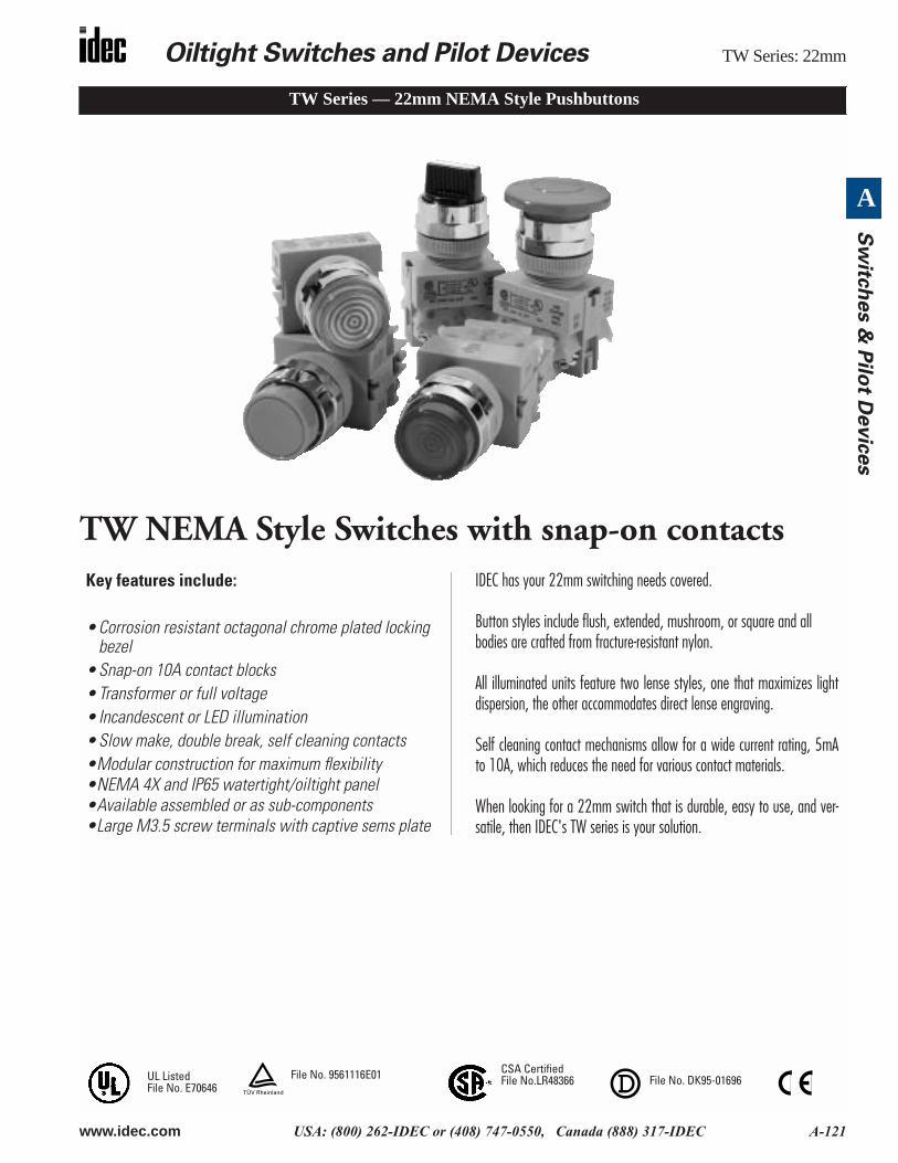
Conforming to Standards EN60947-1, EN60947-5-1, VDE0660-200, UL508, CSA C22-2 No.14
Approvals
CSA: pushbuttons and selector switches: A600pilot lights and illuminated pushbuttons, direct supplypilot lights and illuminated pushbuttons with integral transformer(100/110, 115, 120, 200/220, 230, 240, 380, 400/440, 480V)UL: pushbuttons and selector switches: A600pilot lights and illuminated pushbuttons, direct supplypilot lights and illuminated pushbuttons with integral transformer(100/110, 115, 120, 200/220, 230, 240, 380, 400/440, 480V)TÜV: pushbuttons and selector switches: A600=P600 (NO, NC)/Q600 (NO-EM, NC-LB)pilot lights and illuminated pushbuttons, direct supplypilot lights and illuminated pushbuttons with integral transformer(100/110, 115, 120, 200/220, 230, 240, 380, 400/440, 480V)
Operating Temperature Operation: –25 to +50°C (without freezing)Storage: –40 to +80°C (without freezing)
Vibration Resistance 5 to 55Hz, 100m/sec2 (10g) conforming to IEC6068-2-6
Shock Resistance 1000m/sec2 (100g) conforming to IEC6068-2-7
Electric Shock Protection Class 0 conforming to IEC60536
Degree of Protection (conforming to IEC60529) (conforming to NEMA ICS6-110)
IP65 from front of the panel; (IP54 for key switches)IP20 (Type HW-F contact block)NEMA 1, 2, 3, 3R, 3S, 4, 4X, 5, 12, 13 (NEMA 1, 2, 3R, 5, 12, 13 for key switches)
Mechanical Life Momentary pushbuttons: 5,000,000 (900 operations per hour)All other switches: 500,000
Pollution Degree (conforming to IEC60947-1)
3 for switches not using a transformer2 for switches using a transformer
Rated Operational Characteristics~AC-15: A600 or Ue = 250V, le = 3A (NO, NC, NO-EM, NC-LB)DC-13: P600 or Ue = 125V, le = 1.1A (NO, NC)DC-13: Q600 or Ue = 125V, le = 0.9A (NO-EM, NC-LB)
Rated Insulation Voltage 600V
Rated Switching Over-Voltage Less than 4kV, conforming to IEC60947-1
Rated Impulse Withstanding Voltage 4kV for contact circuit2.5kV for lamp circuit
Rated Thermal Current 10 Amp
Minimum Switching Capacity 5 mA at 3V AC/DC
Contact Operation Slow break NC or slow make NO, self-cleaning
Recommended Terminal Torque 0.8 N m (7.1 in lb.)
External Short-Circuit Protection 10A 250V fuse conforming to IEC60269-1
Applicable Wire Size Minimum 1 x 22 AWG, max. 2 x 14 AWG or 1 x 12 AWG
Contact Resistance Initial contact resistance of 50mΩ or less
Contact Gap 4mm (NO and NC)2mm (NO-EM and NC-LB)
Electrical Reliability MTBF < 1 fault for 10 million operation cycles (3V DC, 5mA)
Lamp Ratings Incandescent: 1 WLEDs: 6V: 17mA max, 12/24V: 11mA max, 120/240V: 10mA max
Horsepower Rating 1/4 HP @ 120V (single-phase, non-reversing motor); 1 HP @ 240V (3 phase, non-revers-ing motor)
Maximum Inrush Current 40 A (40 ms)
Contact Material Silver
Cont
act R
atin
gs
Break Values Make Values
AC DC AC DC
Inductive Resistive Inductive Resistive Inductive Resistive Inductive Resistive
Rated Operating Current 24V:10A120V: 6A240V: 3A480V: 1.5A600V: 1.2 A
24V:10A120V: 10A240V: 6A480V: 2A
24V: 5A110V: 1.1A240V: 0.6A
24V: 10A110V: 2.2A240V: 1.1A480V: 0.4A
120V: 60A240V: 30A480V: 15A600V: 12 A
120V: 100A240V: 60A480V: 20A
120V: 11A240V: 6A12V: 40A24V: 40A
120V: 20A240V: 11A480V: 4A12V: 40A, 24V: 40A
File No. LR21451File No. E68961
Registration No: J9551802 (E-Stops)Registration No: J9551803 (All other switches)Registration No: J9551804 (Pilot Lights)
Oiltight Switches and Pilot Devices TW Series: 22mm
www.idec.com USA: (800) 262-IDEC or (408) 747-0550, Canada (888) 317-IDEC A-123
A
Sw
itch
es &
Pilo
t Devic
es
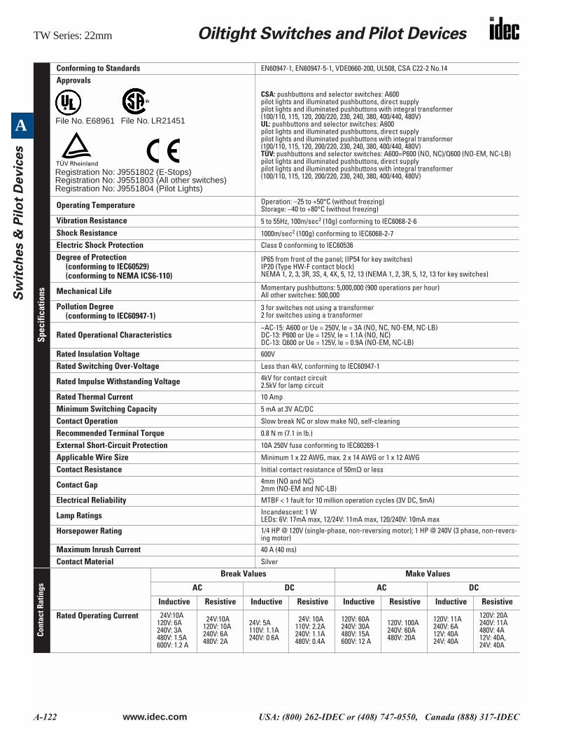
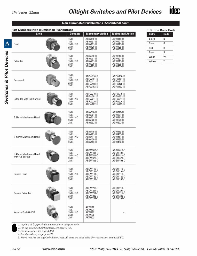
Non-Illuminated Pushbuttons (Assembled)
Assembled Pushbuttons
A B ( ) W 1 10 - B
FunctionB: MomentaryO: MaintainedK: Key On/Off Lock
Bezel ShapeBlank: OctagonalF: Full ShroudG: Mushroom ShroudQ: Square
Button ColorB: Black G: Green W: WhiteR: Red S: Blue Y: Yellow
Terminal StyleBlank: StandardN: Fingersafe (IP20)
Contact Arrangement10: 1NO 01: 1NC20: 2NO 02: 2NC11: 1NO-1NC 22: 2NO-2NC
Button Shape1: Flush2: Extended3: Mushroom Head Ø 29mm4: Mushroom Head Ø 40mm
Series DesignationW:TW Series
( )
To be used for interpreting part numbers only, not for part number development.
TW Series: 22mm Oiltight Switches and Pilot Devices
A-124 www.idec.com USA: (800) 262-IDEC or (408) 747-0550, Canada (888) 317-IDEC
A
Sw
itch
es &
Pil
ot
Devic
es
Part Numbers: Non-illuminated Pushbuttons
Style Contacts Momentary Action Maintained Action
Flush
1NO1NC1NO-1NC2NO2NC
ABW110-➀ABW101-➀ABW111-➀ABW120-➀ABW102-➀
AOW110-➀AOW101-➀AOW111-➀AOW120-➀AOW102-➀
Extended
1NO1NC1NO-1NC2NO2NC
ABW210-➀ABW201-➀ABW211-➀ABW220-➀ABW202-➀
AOW210-➀AOW201-➀AOW211-➀AOW220-➀AOW202-➀
Recessed
1NO1NC1NO-1NC2NO2NC
ABFW110-➀ABFW101-➀ABFW111-➀ABFW120-➀ABFW102-➀
AOFW110-➀AOFW101-➀AOFW111-➀AOFW120-➀AOFW102-➀
Extended with Full Shroud
1NO1NC1NO-1NC2NO2NC
ABFW210-➀ABFW201-➀ABFW211-➀ABFW220-➀ABFW202-➀
AOFW210-➀AOFW201-➀AOFW211-➀AOFW220-➀AOFW202-➀
Ø 29mm Mushroom Head
1NO1NC1NO-1NC2NO2NC
ABW310-➀ABW301-➀ABW311-➀ABW320-➀ABW302-➀
AOW310-➀AOW301-➀AOW311-➀AOW320-➀AOW302-➀
Ø 40mm Mushroom Head
1NO1NC1NO-1NC2NO2NC
ABW410-➀ ABW401-➀ ABW411-➀ ABW420-➀ ABW402-➀
AOW410-➀ AOW401-➀ AOW411-➀ AOW420-➀ AOW402-➀
Ø 40mm Mushroom Head with Full Shroud
1NO1NC1NO-1NC2NO2NC
ABGW410-➀ABGW401-➀ABGW411-➀ABGW420-➀ABGW402-➀
AOGW410-➀AOGW401-➀AOGW411-➀AOGW420-➀AOGW402-➀
Square Flush
1NO1NC1NO-1NC2NO2NC
ABQW110-➀ABQW101-➀ABQW111-➀ABQW120-➀ABQW102-➀
AOQW110-➀AOQW101-➀AOQW111-➀AOQW120-➀AOQW102-➀
Square Extended
1NO1NC1NO-1NC2NO2NC
ABQW210-➀ABQW201-➀ABQW211-➀ ABQW220-➀ ABQW202-➀
AOQW210-➀AOQW201-➀ AOQW211-➀AOQW220-➀ AOQW202-➀
Keylock Push On/Off
1NO1NC1NO-1NC2NO2NC
AKW210AKW201AKW211AKW220AKW202
–
① Button Color Code
Color Code
Black B
Green G
Red R
Blue S
White W
Yellow Y
Non-Illuminated Pushbuttons (Assembled) con’t
1. In place of ➀ , specify the Button Color Code from table.2. For sub-assembled part numbers, see page A-125.3. For accessories, see page A-150.4. For dimensions, see page A-152.5. Keyed switches are supplied with two keys. All units are keyed alike. For custom keys, contact IDEC.
Oiltight Switches and Pilot Devices TW Series: 22mm
www.idec.com USA: (800) 262-IDEC or (408) 747-0550, Canada (888) 317-IDEC A-125
A
Sw
itch
es &
Pilo
t Devic
es
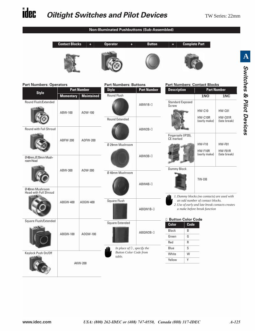
Part Numbers: Operators
Contact Blocks + Operator + Button = Complete Part
StylePart Number
Momentary Maintained
Round Flush/Extended
ABW-100 AOW-100
Round with Full Shroud
ABFW-200 AOFW-200
Ø 40mm, Ø 29mm Mush-room Head
ABW-300 AOW-300
Ø 40mm Mushroom Head with Full Shroud
ABGW-400 AOGW-400
Square Flush/Extended
ABQW-100 AOQW-100
Keylock Push On/Off
AKW-200
Non-Illuminated Pushbuttons (Sub-Assembled)
Part Numbers: Buttons
Style Part NumberRound Flush
ABW1B-➀
Round Extended
ABW2B-➀
Ø 29mm Mushroom
ABW3B-➀
Ø 40mm Mushroom
ABW4B-➀
Square Flush
ABQW1B-➀
Square Extended
ABQW2B-➀
In place of ➀ , specify the Button Color Code from table.
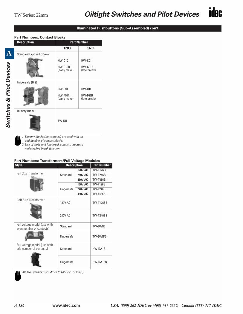
Part Numbers: Contact Blocks
① Button Color Code
Description Part Number
1NO 1NC
Standard Exposed Screw
HW-C10
HW-C10R(early make)
HW-C01
HW-C01R(late break)
Fingersafe (IP20), CE marked
HW-F10
HW-F10R(early make)
HW-F01
HW-F01R(late break)
Dummy Block
TW-DB
Color Code
Black B
Green G
Red R
Blue S
White W
Yellow Y
1. Dummy blocks (no contacts) are used with an odd number of contact blocks.
2. Use of early and late break contacts creates a make before break function
TW Series: 22mm Oiltight Switches and Pilot Devices
A-126 www.idec.com USA: (800) 262-IDEC or (408) 747-0550, Canada (888) 317-IDEC
A
Sw
itch
es &
Pil
ot
Devic
es
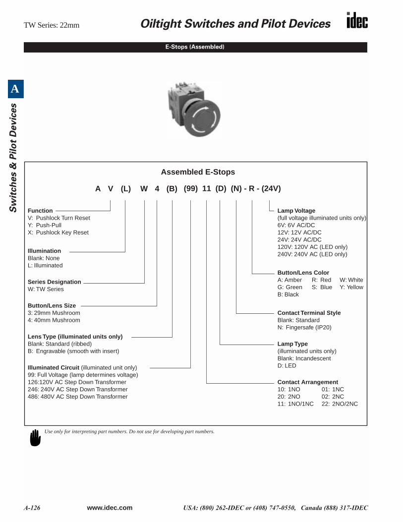
E-Stops (Assembled)
Assembled E-Stops
A V (L) W 4 (B)
FunctionV: Pushlock Turn ResetY: Push-PullX: Pushlock Key Reset
IlluminationBlank: NoneL: Illuminated
Series DesignationW: TW Series
Button/Lens Size3: 29mm Mushroom4: 40mm Mushroom
Lens Type (illuminated units only)Blank: Standard (ribbed)B: Engravable (smooth with insert)
Illuminated Circuit (illuminated unit only)99: Full Voltage (lamp determines voltage)126:120V AC Step Down Transformer246: 240V AC Step Down Transformer486: 480V AC Step Down Transformer
Lamp Voltage (full voltage illuminated units only)6V: 6V AC/DC12V: 12V AC/DC24V: 24V AC/DC120V: 120V AC (LED only)240V: 240V AC (LED only)
Button/Lens ColorA: Amber R: Red W: WhiteG: Green S: Blue Y: YellowB: Black
Contact Terminal StyleBlank: StandardN: Fingersafe (IP20)
Lamp Type(illuminated units only)Blank: IncandescentD: LED
Contact Arrangement10: 1NO 01: 1NC20: 2NO 02: 2NC11: 1NO/1NC 22: 2NO/2NC
(99) 11 (D) (N) - R - (24V)
Use only for interpreting part numbers. Do not use for developing part numbers.
Oiltight Switches and Pilot Devices TW Series: 22mm
www.idec.com USA: (800) 262-IDEC or (408) 747-0550, Canada (888) 317-IDEC A-127
A
Sw
itch
es &
Pilo
t Devic
es
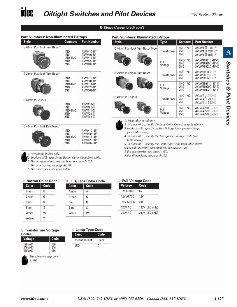
Part Numbers: Non-Illuminated E-Stops
Style Contacts Part Number
Ø 40mm Pushlock Turn Reset*1NO1NC1NO-1NC2NO2NC
AVW410-R*AVW401-R*AVW411-R*AVW420-R*AVW402-R*
Ø 29mm Pushlock Turn Reset*1NO1NC1NO-1NC2NO2NC
AVW310-R*AVW301-R*AVW311-R*AVW320-R*AVW302-R*
Ø 40mm Push-Pull1NO1NC1NO-1NC2NO2NC
AYW410-➀AYW401-➀AYW411-➀AYW420-➀AYW402-➀
Ø 40mm Pushlock Key Reset *1NO1NC1NO-1NC2NO2NC
AXW410- R*AXW401- R*AXW411- R*AXW420- R*AXW402- R*
Part Numbers: Illuminated E-Stops
Style Type Contacts Part Number
Ø 40mm Pushlock Turn Reset TypeTransformer
1NO-1NC2NO2NC
AVLW4 ➃ 11⑤ -R*AVLW4 ➃ 20⑤ -R*AVLW4 ➃ 02⑤ -R*
Full Voltage
1NO-1NC2NO2NC
AVLW49911➄ -R*-➂ AVLW49920➄ -R*-➂ AVLW49902➄ -R*-➂
Ø 29mm Pushlock Turn Reset Transformer
1NO-1NC2NO2NC
AVLW3➃ 11➄ -R*AVLW3➃ 20➄ -R*AVLW3➃ 02➄ -R*
Full Voltage
1NO-1NC2NO2NC
AVLW39911➄ -R*-➂AVLW39920➄ -R*-➂AVLW39902➄ -R*-➂
Ø 40mm Push-Pull Transformer1NO-1NC2NO2NC
AYLW4 ➃ 11➄ -➁AYLW4 ➃ 20➄ -➁AYLW4 ➃ 02➄ -➁
Full Voltage
1NO-1NC2NO2NC
AYLW49911➄ -➁ -➂AYLW49920➄ -➁ -➂AYLW49902➄ -➁ -➂
1. *Available in red only.2. In place of ➁ , specify the Lens Color Code (see table above).3. In place of ➂ , specify the Full Voltage Code (lamp voltage)
(see table above). 4. In place of ➃ , specify the Transformer Voltage Code (see
table above).5. In place of ⑤ , specify the Lamp Type Code from table above.6. For sub-assembly part numbers, see page A-129.7. For accessories, see page A-150.8. For dimensions, see page A-152.
E-Stops (Assembled) con’t
1. *Available in Red only.2. In place of ➀ , specify the Button Color Code from table.3. For sub-assembled part numbers, see page A-125.4. For accessories, see page A-150.5. For dimensions, see page A-152.
① Button Color Code
Color Code
Black B
Green G
Red R
Blue S
White W
Yellow Y
➁ LED/Lens Color Code
Color Code
Amber A
Green G
Red R
Blue S
White W
➂ Full Voltage Code
Voltage Code
6V AC/DC 6V
12V AC/DC 12V
24V AC/DC 24V
120V AC 120V (LED only)
240V AC 240V (LED only)
➄ Lamp Type Code
Lamp Code
Incandescent Blank
LED D
➃ Transformer Voltage Codes
Voltage Code
120VAC240VAC480VAC
126246486
Transformers step down to 6V.
TW Series: 22mm Oiltight Switches and Pilot Devices
A-128 www.idec.com USA: (800) 262-IDEC or (408) 747-0550, Canada (888) 317-IDEC
A
Sw
itch
es &
Pil
ot
Devic
es
Part Numbers: Operators
Part Numbers: Lamps
Part Numbers: Buttons
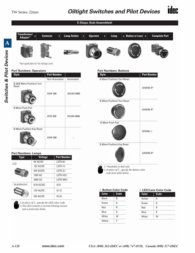
E-Stops (Sub-Assembled)
Transformer/Adaptor* + Contacts + Lamp Holder + Operator + Lamp + Button or Lens = Complete Part
* Not applicable for full voltage units
Style Part Number
Non-illuminated Illuminated
Ø 29/Ø 40mm Pushlock Turn Reset
AVW-300 AVLW3-0600
Ø 40mm Push-Pull
AYW-400 AYLW4-0600
Ø 40mm Pushlock Key Reset
AXW-300 —
Type Voltage Part Number
LED6V AC/DC LSTD-6➁
12V AC/DC LSTD-1➁
24V AC/DC LSTD-2➁
120V AC LSTD-H2➁
240V AC LSTD-M4➁
Incandescent 6.3V AC/DC IS-6
12V AC/DC IS-12
24V AC/DC IS-24
1. In place of ➁ , specify the LED color code.2. The LED contains a current-limiting resistor
and a protection diode.
Style Part Number
Ø 40mm Pushlock Turn Reset
AVW4B-R*
Ø 29mm Pushlock Turn Reset
AVW3B-R*
Ø 40mm Push-Pull
AYW4B-➀
Ø 40mm Pushlock Key Reset
AXW4B-R*
1. *Available in Red only2. In place of ➀ , specify the button color
code from table below.
① Button Color Code
Color Code
Black B
Green G
Red R
Blue S
White W
Yellow Y
➁ LED/Lens Color Code
Color Code
Amber A
Green G
Red R
Blue S
White W
Oiltight Switches and Pilot Devices
TW Series: 22mm
www.idec.com
USA: (800) 262-IDEC or (408) 747-0550, Canada (888) 317-IDEC A-129
A
S
witc
hes &
Pilo
t Devic
es
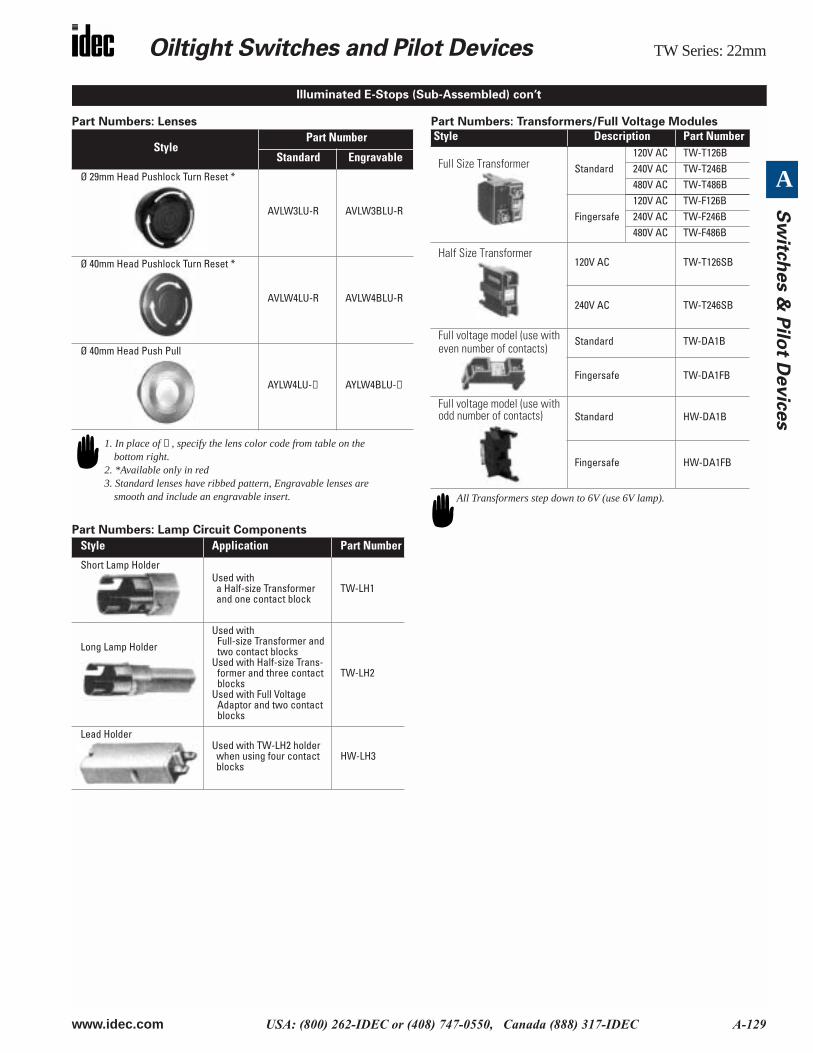
Part Numbers: Lenses
Part Numbers: Lamp Circuit Components
Part Numbers: Transformers/Full Voltage Modules
StylePart Number
Standard Engravable
Ø 29mm Head Pushlock Turn Reset *
AVLW3LU-R AVLW3BLU-R
Ø 40mm Head Pushlock Turn Reset *
AVLW4LU-R AVLW4BLU-R
Ø 40mm Head Push Pull
AYLW4LU-
➁
AYLW4BLU-
➁
Style Application Part Number
Short Lamp HolderUsed with a Half-size Transformer and one contact block
TW-LH1
Long Lamp Holder
Used with Full-size Transformer and two contact blocks
Used with Half-size Trans-former and three contact blocks
Used with Full Voltage Adaptor and two contact blocks
TW-LH2
Lead HolderUsed with TW-LH2 holder when using four contact blocks
HW-LH3
1. In place of ➁ , specify the lens color code from table on the bottom right.
2. *Available only in red3. Standard lenses have ribbed pattern, Engravable lenses are
smooth and include an engravable insert.
Illuminated E-Stops (Sub-Assembled) con’t
Style Description Part Number
Full Size Transformer
Standard120V AC TW-T126B240V AC TW-T246B480V AC TW-T486B
Fingersafe120V AC TW-F126B240V AC TW-F246B480V AC TW-F486B
Half Size Transformer
120V AC TW-T126SB
240V AC TW-T246SB
Full voltage model (use with even number of contacts)
Standard TW-DA1B
Fingersafe TW-DA1FB
Full voltage model (use with odd number of contacts)
Standard HW-DA1B
Fingersafe HW-DA1FB
All Transformers step down to 6V (use 6V lamp).
TW Series: 22mm
Oiltight Switches and Pilot Devices
A-130
www.idec.com
USA: (800) 262-IDEC or (408) 747-0550, Canada (888) 317-IDEC
A
S
wit
ch
es &
Pil
ot
Devic
es
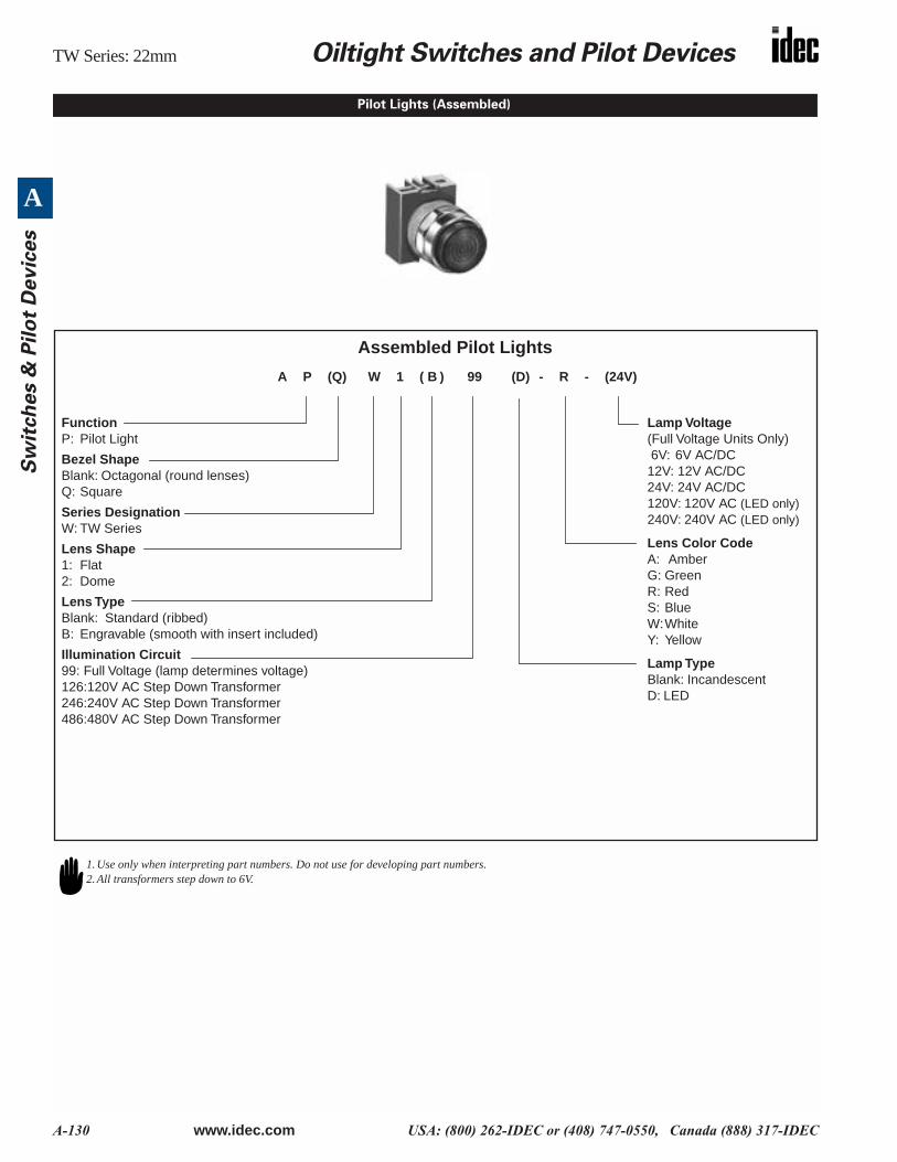
Pilot Lights (Assembled)
Assembled Pilot Lights
FunctionP: Pilot Light
Bezel ShapeBlank: Octagonal (round lenses)Q: Square
Series DesignationW: TW Series
Lens Shape1: Flat2: Dome
Lens TypeBlank: Standard (ribbed)B: Engravable (smooth with insert included)
Illumination Circuit99: Full Voltage (lamp determines voltage)126:120V AC Step Down Transformer246:240V AC Step Down Transformer486:480V AC Step Down Transformer
Lamp Voltage(Full Voltage Units Only) 6V: 6V AC/DC12V: 12V AC/DC24V: 24V AC/DC120V: 120V AC (LED only)240V: 240V AC (LED only)
Lens Color CodeA: AmberG: GreenR: RedS: BlueW:WhiteY: Yellow
Lamp TypeBlank: Incandescent D: LED
A P (Q) W 1 ( B ) 99 (D) - R - (24V)
1. Use only when interpreting part numbers. Do not use for developing part numbers.2. All transformers step down to 6V.
Oiltight Switches and Pilot Devices
TW Series: 22mm
www.idec.com
USA: (800) 262-IDEC or (408) 747-0550, Canada (888) 317-IDEC A-131
A
S
witc
hes &
Pilo
t Devic
es
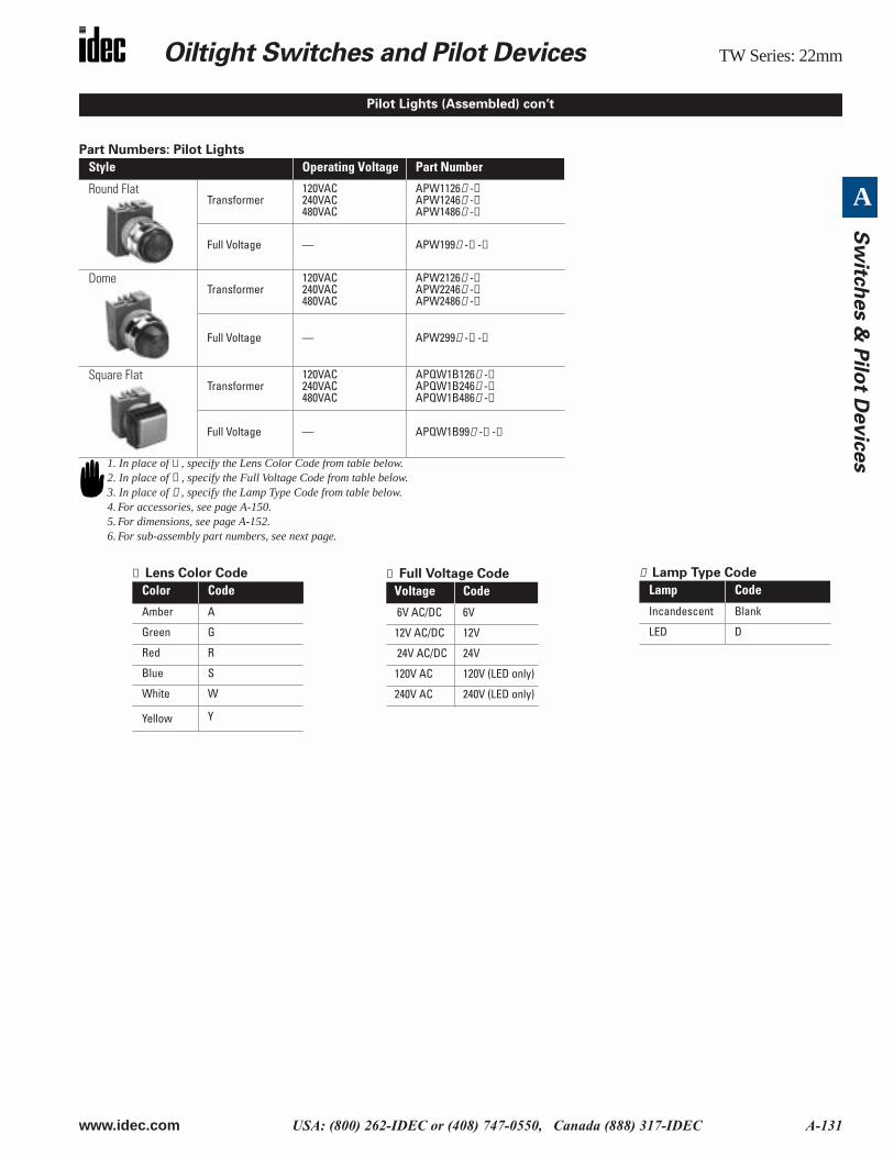
Part Numbers: Pilot Lights
Style Operating Voltage Part Number
Round Flat
Transformer120VAC240VAC480VAC
APW1126
➃
-
➁
APW1246
➃
-
➁
APW1486
➃
-
➁
Full Voltage — APW199
➃
-
➁
-
➂
Dome
Transformer120VAC240VAC480VAC
APW2126
➃
-
➁
APW2246
➃
-
➁
APW2486
➃
-
➁
Full Voltage — APW299
➃
-
➁
-
➂
Square Flat
Transformer120VAC240VAC480VAC
APQW1B126
➃
-
➁
APQW1B246
➃
-
➁
APQW1B486
➃
-
➁
Full Voltage — APQW1B99
➃
-
➁
-
➂
Pilot Lights (Assembled) con’t
1. In place of ➁ , specify the Lens Color Code from table below.2. In place of ➂ , specify the Full Voltage Code from table below.3. In place of ➃ , specify the Lamp Type Code from table below.4. For accessories, see page A-150.5. For dimensions, see page A-152.6. For sub-assembly part numbers, see next page.
➁ Lens Color Code
Color Code
Amber A
Green G
Red R
Blue S
White W
Yellow Y
➃ Lamp Type Code
Lamp Code
Incandescent Blank
LED D
➂ Full Voltage Code
Voltage Code
6V AC/DC 6V
12V AC/DC 12V
24V AC/DC 24V
120V AC 120V (LED only)
240V AC 240V (LED only)
TW Series: 22mm
Oiltight Switches and Pilot Devices
A-132
www.idec.com
USA: (800) 262-IDEC or (408) 747-0550, Canada (888) 317-IDEC
A
S
wit
ch
es &
Pil
ot
Devic
es
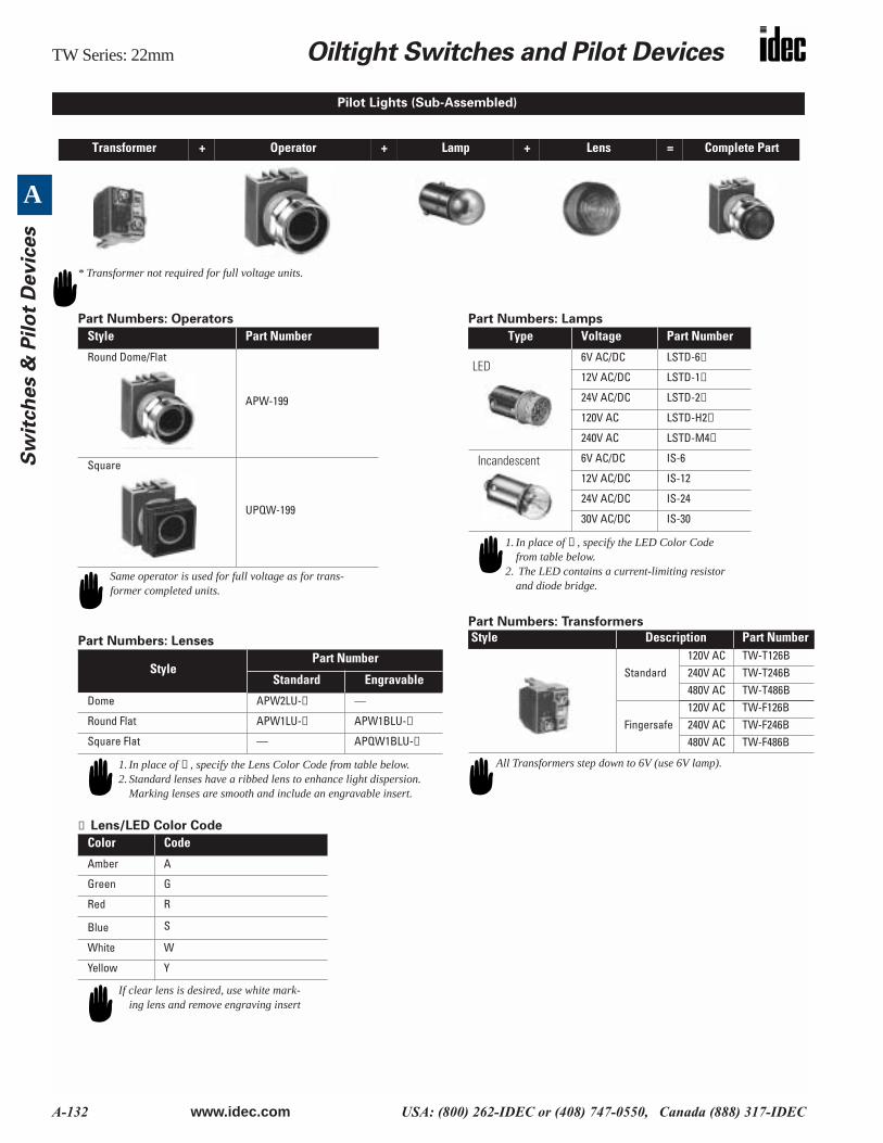
Transformer + Operator + Lamp + Lens = Complete Part
Pilot Lights (Sub-Assembled)
* Transformer not required for full voltage units.
Part Numbers: Operators
Part Numbers: Lenses
➁
Lens/LED Color Code
Part Numbers: Lamps
Part Numbers: Transformers
Style Part Number
Round Dome/Flat
APW-199
Square
UPQW-199
StylePart Number
Standard Engravable
Dome APW2LU-
➁
—
Round Flat APW1LU-
➁
APW1BLU-
➁
Square Flat — APQW1BLU-
➁
Color Code
Amber A
Green G
Red R
Blue S
White W
Yellow Y
Same operator is used for full voltage as for trans-former completed units.
1. In place of ➁ , specify the Lens Color Code from table below.2. Standard lenses have a ribbed lens to enhance light dispersion.
Marking lenses are smooth and include an engravable insert.
If clear lens is desired, use white mark-ing lens and remove engraving insert
Type Voltage Part Number
LED
6V AC/DC LSTD-6
➁
12V AC/DC LSTD-1
➁
24V AC/DC LSTD-2
➁
120V AC LSTD-H2
➁
240V AC LSTD-M4
➁
Incandescent
6V AC/DC IS-6
12V AC/DC IS-12
24V AC/DC IS-24
30V AC/DC IS-30
Style Description Part Number
Standard120V AC TW-T126B240V AC TW-T246B480V AC TW-T486B
Fingersafe120V AC TW-F126B240V AC TW-F246B480V AC TW-F486B
1. In place of ➁ , specify the LED Color Code from table below.
2. The LED contains a current-limiting resistor and diode bridge.
All Transformers step down to 6V (use 6V lamp).
Oiltight Switches and Pilot Devices
TW Series: 22mm
www.idec.com
USA: (800) 262-IDEC or (408) 747-0550, Canada (888) 317-IDEC A-133
A
S
witc
hes &
Pilo
t Devic
es
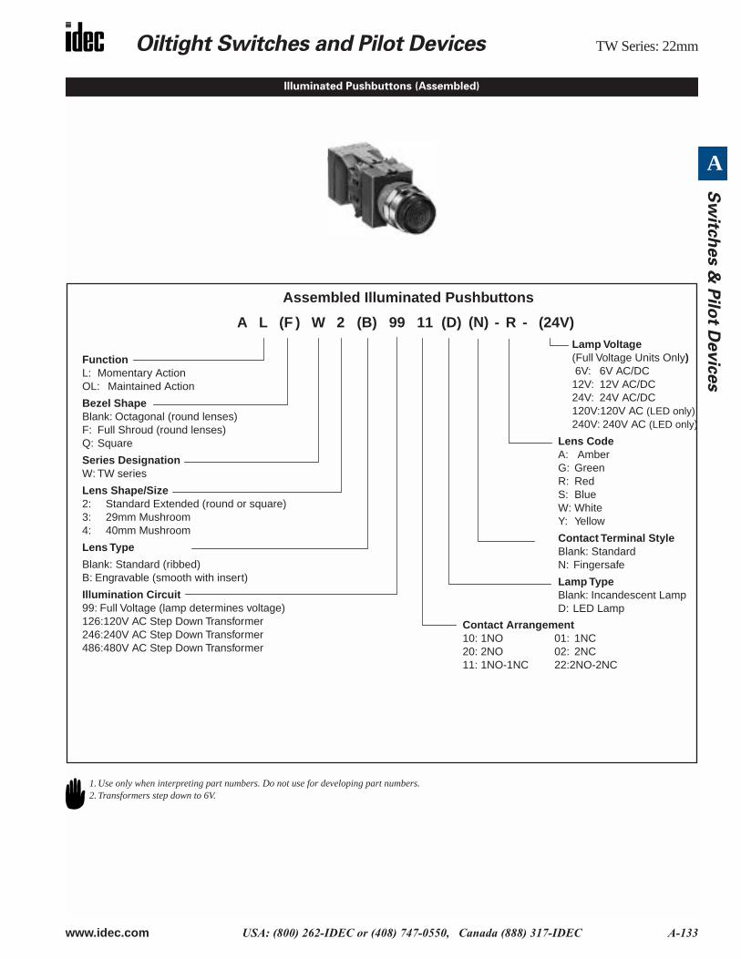
Illuminated Pushbuttons (Assembled)
Assembled Illuminated Pushbuttons
FunctionL: Momentary ActionOL: Maintained Action
Bezel ShapeBlank: Octagonal (round lenses)F: Full Shroud (round lenses)Q: Square
Series DesignationW: TW series
Lens Shape/Size2: Standard Extended (round or square)3: 29mm Mushroom4: 40mm Mushroom
Lens Type
Blank: Standard (ribbed)B: Engravable (smooth with insert)
Illumination Circuit99: Full Voltage (lamp determines voltage) 126:120V AC Step Down Transformer246:240V AC Step Down Transformer486:480V AC Step Down Transformer
Lamp Voltage(Full Voltage Units Only) 6V: 6V AC/DC12V: 12V AC/DC24V: 24V AC/DC120V:120V AC (LED only)240V: 240V AC (LED only)
Lens CodeA: AmberG: GreenR: RedS: BlueW: WhiteY: Yellow
Contact Terminal StyleBlank: StandardN: Fingersafe
Lamp TypeBlank: Incandescent LampD: LED Lamp
A L (F ) W 2 (B) 99 11 (D) - R - (24V)
Contact Arrangement10: 1NO 01: 1NC20: 2NO 02: 2NC11: 1NO-1NC 22:2NO-2NC
(N)
1. Use only when interpreting part numbers. Do not use for developing part numbers.2. Transformers step down to 6V.
TW Series: 22mm
Oiltight Switches and Pilot Devices
A-134
www.idec.com
USA: (800) 262-IDEC or (408) 747-0550, Canada (888) 317-IDEC
A
S
wit
ch
es &
Pil
ot
Devic
es
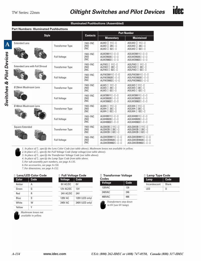
Part Numbers: Illuminated Pushbuttons
Style ContactsPart Number
Momentary Maintained
Extended LensTransformer Type
1NO-1NC2NO2NC
ALW2
➃
11
⑤
-
➁
ALW2 ➃ 20⑤ -➁ALW2 ➃ 02⑤ -➁
AOLW2 ➃ 11⑤ -➁AOLW2 ➃ 20⑤ -➁AOLW2 ➃ 02⑤ -➁
Full Voltage1NO-1NC2NO2NC
ALW29911⑤ -➁ -➂ ALW29920⑤ -➁ -➂ ALW29902⑤ -➁ -➂
AOLW29911⑤ -➁ -➂ AOLW29920⑤ -➁ -➂ AOLW29902⑤ -➁ -➂
Extended Lens with Full Shroud Transformer Type1NO-1NC2NO2NC
ALFW2 ➃ 11⑤ -➁ALFW2 ➃ 20⑤ -➁ALFW2 ➃ 02⑤ -➁
AOLFW2 ➃ 11⑤ -➁AOLFW2 ➃ 20⑤ -➁AOLFW2 ➃ 02⑤ -➁
Full Voltage1NO-1NC2NO2NC
ALFW29911⑤ -➁ -➂ ALFW29920⑤ -➁ -➂ ALFW29902⑤ -➁ -➂
AOLFW29911⑤ -➁ -➂ AOLFW29920⑤ -➁ -➂ AOLFW29902⑤ -➁ -➂
Ø 29mm Mushroom Lens Transformer Type1NO-1NC2NO2NC
ALW3 ➃ 11⑤ -➁ALW3 ➃ 20⑤ -➁ALW3 ➃ 02⑤ -➁
AOLW3 ➃ 11⑤ -➁AOLW3 ➃ 20⑤ -➁AOLW3 ➃ 02⑤ -➁
Full Voltage1NO-1NC2NO2NC
ALW39911⑤ -➁ -➂ ALW39920⑤ -➁ -➂ ALW39902⑤ -➁ -➂
AOLW39911⑤ -➁ -➂ AOLW39920⑤ -➁ -➂ AOLW39902⑤ -➁ -➂
Ø 40mm Mushroom LensTransformer Type
1NO-1NC2NO2NC
ALW4 ➃ 11⑤ -➁ALW4 ➃ 20⑤ -➁ALW4 ➃ 02⑤ -➁
AOLW4 ➃ 11⑤ -➁AOLW4 ➃ 20⑤ -➁AOLW4 ➃ 02⑤ -➁
Full Voltage1NO-1NC2NO2NC
ALW49911⑤ -➁ -➂ ALW49920⑤ -➁ -➂ ALW49902⑤ -➁ -➂
AOLW49911⑤ -➁ -➂ AOLW49920⑤ -➁ -➂ AOLW49902⑤ -➁ -➂
Square Extended Transformer Type
1NO-1NC2NO2NC
ALQW2B ➃ 11⑤ -➁ALQW2B ➃ 20⑤ -➁ALQW2B ➃ 02⑤ -➁
AOLQW2B ➃ 11⑤ -➁AOLQW2B ➃ 20⑤ -➁AOLQW2B ➃ 02⑤ -➁
Full Voltage1NO-1NC2NO2NC
ALQW2B9911⑤ -➁ -➂ ALQW2B9920⑤ -➁ -➂ ALQW2B9902⑤ -➁ -➂
AOLQW2B9911⑤ -➁ -➂ AOLQW2B9920⑤ -➁ -➂ AOLQW2B9902⑤ -➁ -➂
Illuminated Pushbuttons (Assembled)
1. In place of ➁ , specify the Lens Color Code (see table above). Mushroom lenses not available in yellow.2. In place of ➂ , specify the Full Voltage Code (lamp voltage) (see table above). 3. In place of ➃ , specify the Transformer Voltage Code (see table above).4. In place of ⑤ , specify the Lamp Type Code from table above.5. For sub-assembly part numbers, see page A-135.6. For accessories, see page A-150.7. For dimensions, see page A-152.
➁ Lens/LED Color Code
Color Code
Amber A
Green G
Red R
Blue S
White W
Yellow Y
Mushroom lenses not available in yellow.
➂ Full Voltage Code
Voltage Code
6V AC/DC 6V
12V AC/DC 12V
24V AC/DC 24V
120V AC 120V (LED only)
240V AC 240V (LED only)
➃ Transformer Voltage Codes
Voltage Code
120VAC 126
240VAC 246
480VAC 486
Transformers step down to 6V (use 6V lamp).
⑤ Lamp Type Code
Lamp Code
Incandescent Blank
LED D
Oiltight Switches and Pilot Devices TW Series: 22mm
www.idec.com USA: (800) 262-IDEC or (408) 747-0550, Canada (888) 317-IDEC A-135
A
Sw
itch
es &
Pilo
t Devic
es
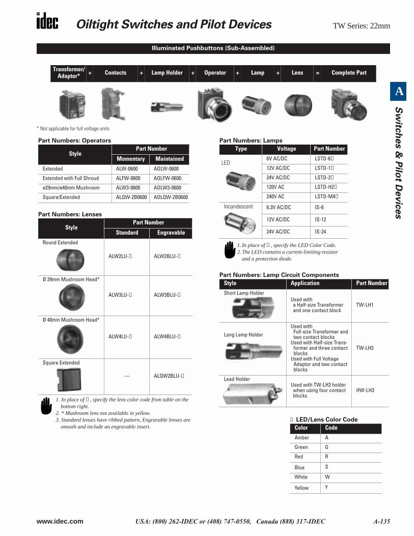
* Not applicable for full voltage units
Transformer/Adaptor* + Contacts + Lamp Holder + Operator + Lamp + Lens = Complete Part
Illuminated Pushbuttons (Sub-Assembled)
Part Numbers: Operators
Part Numbers: Lenses
Part Numbers: Lamps
Part Numbers: Lamp Circuit Components
Style Part Number
Momentary Maintained
Extended ALW-0600 AOLW-0600
Extended with Full Shroud ALFW-0600 AOLFW-0600
ø29mm/ø40mm Mushroom ALW3-0600 AOLW3-0600
Square/Extended ALQW-2B0600 AOLQW-2B0600
StylePart Number
Standard Engravable
Round Extended
ALW2LU-➁ ALW2BLU-➁
Ø 29mm Mushroom Head*
ALW3LU-➁ ALW3BLU-➁
Ø 40mm Mushroom Head*
ALW4LU-➁ ALW4BLU-➁
Square Extended
— ALQW2BLU-➁
1. In place of ➁ , specify the lens color code from table on the bottom right.
2. * Mushroom lens not available in yellow.3. Standard lenses have ribbed pattern, Engravable lenses are
smooth and include an engravable insert.
Type Voltage Part Number
LED6V AC/DC LSTD-6➁
12V AC/DC LSTD-1➁
24V AC/DC LSTD-2➁
120V AC LSTD-H2➁
240V AC LSTD-M4➁
Incandescent 6.3V AC/DC IS-6
12V AC/DC IS-12
24V AC/DC IS-24
Style Application Part Number
Short Lamp HolderUsed with a Half-size Transformer and one contact block
TW-LH1
Long Lamp Holder
Used with Full-size Transformer and two contact blocks
Used with Half-size Trans-former and three contact blocks
Used with Full Voltage Adaptor and two contact blocks
TW-LH2
Lead HolderUsed with TW-LH2 holder when using four contact blocks
HW-LH3
1. In place of ➁ , specify the LED Color Code.2. The LED contains a current-limiting resistor
and a protection diode.
➁ LED/Lens Color Code
Color Code
Amber A
Green G
Red R
Blue S
White W
Yellow Y
TW Series: 22mm Oiltight Switches and Pilot Devices
A-136 www.idec.com USA: (800) 262-IDEC or (408) 747-0550, Canada (888) 317-IDEC
A
Sw
itch
es &
Pil
ot
Devic
es
Part Numbers: Contact Blocks
Part Numbers: Transformers/Full Voltage Modules
Description Part Number
1NO 1NC
Standard Exposed Screw
HW-C10
HW-C10R(early make)
HW-C01
HW-C01R(late break)
Fingersafe (IP20)
HW-F10
HW-F10R(early make)
HW-F01
HW-F01R(late break)
Dummy Block
TW-DB
Style Description Part Number
Full Size Transformer Standard120V AC TW-T126B240V AC TW-T246B480V AC TW-T486B
Fingersafe120V AC TW-F126B240V AC TW-F246B480V AC TW-F486B
Half Size Transformer120V AC TW-T126SB
240V AC TW-T246SB
Full voltage model (use with even number of contacts)
Standard TW-DA1B
Fingersafe TW-DA1FB
Full voltage model (use with odd number of contacts) Standard HW-DA1B
Fingersafe HW-DA1FB
1. Dummy blocks (no contacts) are used with an odd number of contact blocks.
2. Use of early and late break contacts creates a make before break function
Illuminated Pushbuttons (Sub-Assembled) con’t
All Transformers step down to 6V (use 6V lamp).
Oiltight Switches and Pilot Devices TW Series: 22mm
www.idec.com USA: (800) 262-IDEC or (408) 747-0550, Canada (888) 317-IDEC A-137
A
Sw
itch
es &
Pilo
t Devic
es
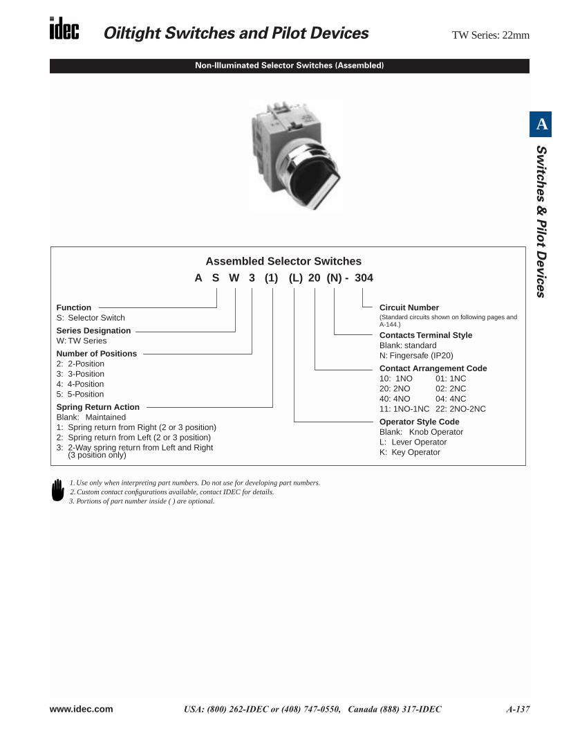
Non-Illuminated Selector Switches (Assembled)
Assembled Selector Switches
FunctionS: Selector Switch
Series DesignationW: TW Series
Number of Positions2: 2-Position3: 3-Position4: 4-Position5: 5-Position
Spring Return ActionBlank: Maintained1: Spring return from Right (2 or 3 position)2: Spring return from Left (2 or 3 position)3: 2-Way spring return from Left and Right (3 position only)
Circuit Number(Standard circuits shown on following pages and A-144.)
Contacts Terminal StyleBlank: standardN: Fingersafe (IP20)
Contact Arrangement Code10: 1NO 01: 1NC20: 2NO 02: 2NC40: 4NO 04: 4NC11: 1NO-1NC 22: 2NO-2NC
Operator Style CodeBlank: Knob OperatorL: Lever OperatorK: Key Operator
A S W 3 (1) (L) 20 (N) - 304
1. Use only when interpreting part numbers. Do not use for developing part numbers.2. Custom contact configurations available, contact IDEC for details.3. Portions of part number inside ( ) are optional.
TW Series: 22mm Oiltight Switches and Pilot Devices
A-138 www.idec.com USA: (800) 262-IDEC or (408) 747-0550, Canada (888) 317-IDEC
A
Sw
itch
es &
Pil
ot
Devic
es
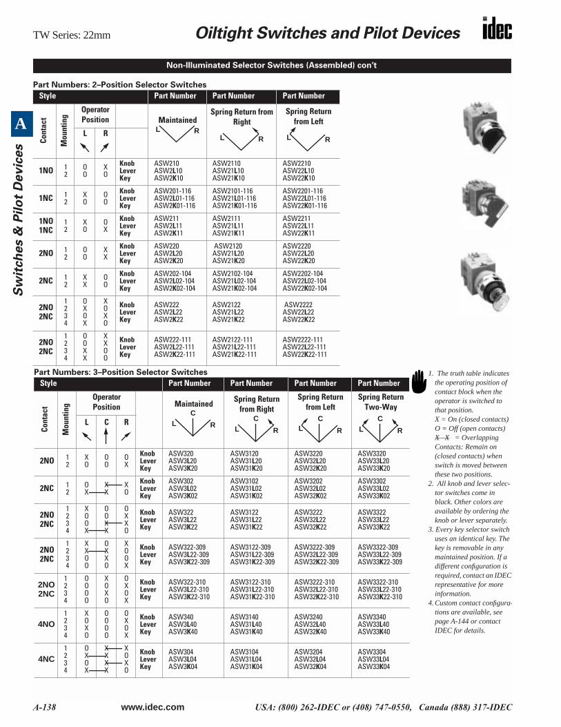
Part Numbers: 2–Position Selector Switches
Style Part Number Part Number Part Number
Cont
act
Mou
ntin
g
OperatorPosition Maintained
Spring Return from Right
Spring Return from Left
L R
1NO 12
OO
XO
KnobLeverKey
ASW210 ASW2L10ASW2K10
ASW2110ASW21L10ASW21K10
ASW2210ASW22L10ASW22K10
1NC 12
XO
OO
KnobLeverKey
ASW201-116 ASW2L01-116ASW2K01-116
ASW2101-116ASW21L01-116ASW21K01-116
ASW2201-116ASW22L01-116ASW22K01-116
1NO1NC
12
XO
OX
KnobLeverKey
ASW211ASW2L11ASW2K11
ASW2111ASW21L11ASW21K11
ASW2211ASW22L11ASW22K11
2NO 12
OO
XX
KnobLeverKey
ASW220ASW2L20ASW2K20
ASW2120 ASW21L20ASW21K20
ASW2220ASW22L20ASW22K20
2NC 12
XX
OO
KnobLeverKey
ASW202-104ASW2L02-104ASW2K02-104
ASW2102-104ASW21L02-104ASW21K02-104
ASW2202-104ASW22L02-104ASW22K02-104
2NO2NC
1234
OXOX
XOXO
KnobLeverKey
ASW222ASW2L22ASW2K22
ASW2122ASW21L22ASW21K22
ASW2222ASW22L22ASW22K22
2NO2NC
1234
OOXX
XXOO
KnobLeverKey
ASW222-111ASW2L22-111ASW2K22-111
ASW2122-111ASW21L22-111ASW21K22-111
ASW2222-111ASW22L22-111ASW22K22-111
Non-Illuminated Selector Switches (Assembled) con’t
L RL R L R
Part Numbers: 3–Position Selector Switches
Style Part Number Part Number Part Number Part Number
Cont
act
Mou
ntin
g
OperatorPosition Maintained Spring Return
from RightSpring Return
from LeftSpring Return
Two-Way
L C R
2NO 12
XO
OO
OX
KnobLeverKey
ASW320ASW3L20ASW3K20
ASW3120ASW31L20ASW31K20
ASW3220ASW32L20ASW32K20
ASW3320ASW33L20ASW33K20
2NC 12
OX
XX
XO
KnobLeverKey
ASW302ASW3L02ASW3K02
ASW3102ASW31L02ASW31K02
ASW3202ASW32L02ASW32K02
ASW3302ASW33L02ASW33K02
2NO2NC
1234
XOOX
OOXX
OXXO
KnobLeverKey
ASW322ASW3L22ASW3K22
ASW3122ASW31L22ASW31K22
ASW3222ASW32L22ASW32K22
ASW3322ASW33L22ASW33K22
2NO2NC
1234
XXOO
OXXO
XOOX
KnobLeverKey
ASW322-309ASW3L22-309ASW3K22-309
ASW3122-309ASW31L22-309ASW31K22-309
ASW3222-309ASW32L22-309ASW32K22-309
ASW3322-309ASW33L22-309ASW33K22-309
2NO2NC
1234
OOOO
XOXO
OXOX
KnobLeverKey
ASW322-310ASW3L22-310ASW3K22-310
ASW3122-310ASW31L22-310ASW31K22-310
ASW3222-310ASW32L22-310ASW32K22-310
ASW3322-310ASW33L22-310ASW33K22-310
4NO1234
XOXO
OOOO
OXOX
KnobLeverKey
ASW340ASW3L40ASW3K40
ASW3140ASW31L40ASW31K40
ASW3240ASW32L40ASW32K40
ASW3340ASW33L40ASW33K40
4NC1234
OXOX
XXXX
XOXO
KnobLeverKey
ASW304ASW3L04ASW3K04
ASW3104ASW31L04ASW31K04
ASW3204ASW32L04ASW32K04
ASW3304ASW33L04ASW33K04
LC
R LC
R LC
R LC
R
1. The truth table indicates the operating position of contact block when the operator is switched to that position.X = On (closed contacts) O = Off (open contacts)X X = Overlapping Contacts: Remain on (closed contacts) when switch is moved between these two positions.
2. All knob and lever selec-tor switches come in black. Other colors are available by ordering the knob or lever separately.
3. Every key selector switch uses an identical key. The key is removable in any maintained position. If a different configuration is required, contact an IDEC representative for more information.
4. Custom contact configura-tions are available, see page A-144 or contact IDEC for details.
Oiltight Switches and Pilot Devices TW Series: 22mm
www.idec.com USA: (800) 262-IDEC or (408) 747-0550, Canada (888) 317-IDEC A-139
A
Sw
itch
es &
Pilo
t Devic
es
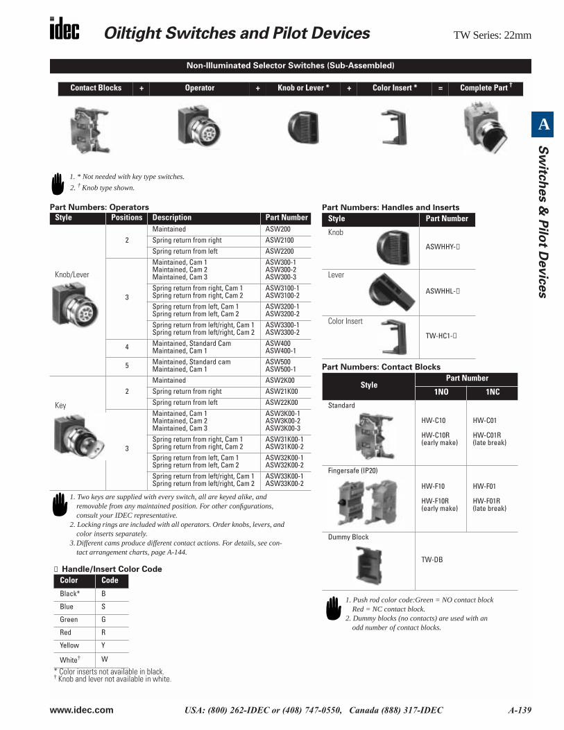
Part Numbers: Operators
Contact Blocks + Operator + Knob or Lever * + Color Insert * = Complete Part †
Style Positions Description Part Number
Knob/Lever
2Maintained ASW200Spring return from right ASW2100Spring return from left ASW2200
3
Maintained, Cam 1Maintained, Cam 2Maintained, Cam 3
ASW300-1ASW300-2ASW300-3
Spring return from right, Cam 1Spring return from right, Cam 2
ASW3100-1ASW3100-2
Spring return from left, Cam 1Spring return from left, Cam 2
ASW3200-1ASW3200-2
Spring return from left/right, Cam 1Spring return from left/right, Cam 2
ASW3300-1ASW3300-2
4 Maintained, Standard CamMaintained, Cam 1
ASW400ASW400-1
5 Maintained, Standard camMaintained, Cam 1
ASW500ASW500-1
Key
2Maintained ASW2K00Spring return from right ASW21K00Spring return from left ASW22K00
3
Maintained, Cam 1Maintained, Cam 2Maintained, Cam 3
ASW3K00-1ASW3K00-2ASW3K00-3
Spring return from right, Cam 1Spring return from right, Cam 2
ASW31K00-1ASW31K00-2
Spring return from left, Cam 1Spring return from left, Cam 2
ASW32K00-1ASW32K00-2
Spring return from left/right, Cam 1Spring return from left/right, Cam 2
ASW33K00-1ASW33K00-2
Non-Illuminated Selector Switches (Sub-Assembled)
1. * Not needed with key type switches.
2. † Knob type shown.
Part Numbers: Handles and Inserts
Part Numbers: Contact Blocks
Style Part Number
Knob
ASWHHY-①
Lever
ASWHHL-①
Color Insert
TW-HC1-①
StylePart Number
1NO 1NC
Standard
HW-C10
HW-C10R(early make)
HW-C01
HW-C01R(late break)
Fingersafe (IP20)
HW-F10
HW-F10R(early make)
HW-F01
HW-F01R(late break)
Dummy Block
TW-DB
1. Push rod color code:Green = NO contact block Red = NC contact block.
2. Dummy blocks (no contacts) are used with an odd number of contact blocks.
1. Two keys are supplied with every switch, all are keyed alike, and removable from any maintained position. For other configurations, consult your IDEC representative.
2. Locking rings are included with all operators. Order knobs, levers, and color inserts separately.
3. Different cams produce different contact actions. For details, see con-tact arrangement charts, page A-144.
① Handle/Insert Color Code
* Color inserts not available in black.† Knob and lever not available in white.
Color Code
Black* B
Blue S
Green G
Red R
Yellow Y
White† W
TW Series: 22mm Oiltight Switches and Pilot Devices
A-140 www.idec.com USA: (800) 262-IDEC or (408) 747-0550, Canada (888) 317-IDEC
A
Sw
itch
es &
Pil
ot
Devic
es
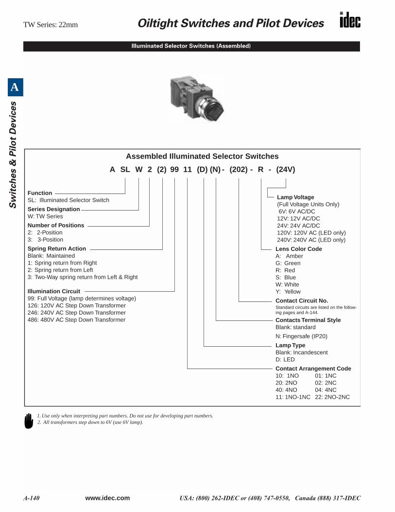
Illuminated Selector Switches (Assembled)
Assembled Illuminated Selector Switches
FunctionSL: Illuminated Selector Switch
Series DesignationW: TW Series
Number of Positions2: 2-Position3: 3-Position
Spring Return ActionBlank: Maintained1: Spring return from Right2: Spring return from Left3: Two-Way spring return from Left & Right
Illumination Circuit99: Full Voltage (lamp determines voltage)126: 120V AC Step Down Transformer246: 240V AC Step Down Transformer486: 480V AC Step Down Transformer
Lamp Voltage(Full Voltage Units Only) 6V: 6V AC/DC12V: 12V AC/DC24V: 24V AC/DC120V: 120V AC (LED only)240V: 240V AC (LED only)
Lens Color CodeA: AmberG: GreenR: RedS: BlueW: WhiteY: Yellow
Contact Circuit No.Standard circuits are listed on the follow-ing pages and A-144.
Contacts Terminal StyleBlank: standard
N: Fingersafe (IP20)
Lamp TypeBlank: Incandescent D: LED
Contact Arrangement Code10: 1NO 01: 1NC20: 2NO 02: 2NC40: 4NO 04: 4NC11: 1NO-1NC 22: 2NO-2NC
A SL W (2)2 99 11 (D) (N) - (202) - R - (24V)
1. Use only when interpreting part numbers. Do not use for developing part numbers.2. All transformers step down to 6V (use 6V lamp).
Oiltight Switches and Pilot Devices TW Series: 22mm
www.idec.com USA: (800) 262-IDEC or (408) 747-0550, Canada (888) 317-IDEC A-141
A
Sw
itch
es &
Pilo
t Devic
es
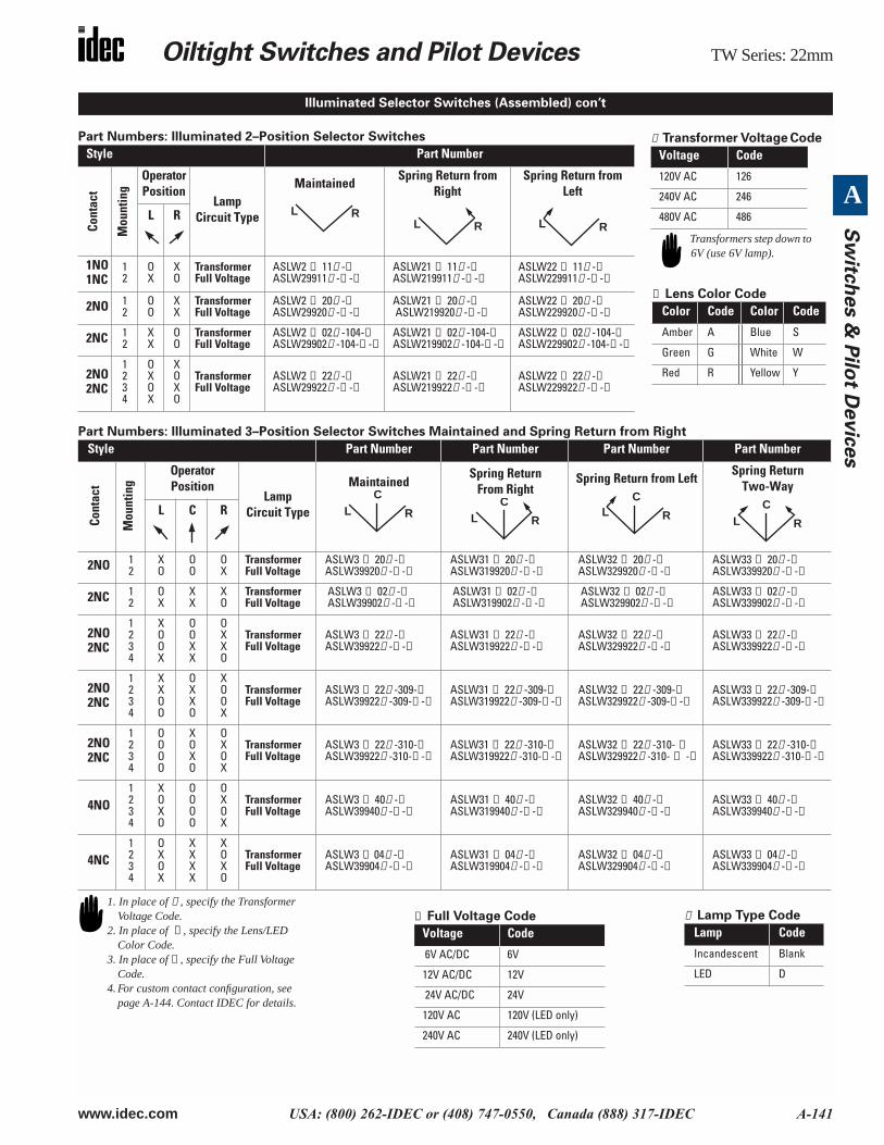
Part Numbers: Illuminated 2–Position Selector Switches
Part Numbers: Illuminated 3–Position Selector Switches Maintained and Spring Return from Right
Style Part Number
Cont
act
Mou
ntin
g
OperatorPosition
Lamp Circuit Type
MaintainedSpring Return from
RightSpring Return from
Left
L R
1NO1NC
12
OX
XO
TransformerFull Voltage
ASLW2 ➀ 11➃ -➁ASLW29911➃ -➁ -➂
ASLW21 ➀ 11➃ -➁ASLW219911➃ -➁ -➂
ASLW22 ➀ 11➃ -➁ASLW229911➃ -➁ -➂
2NO 12
OO
XX
TransformerFull Voltage
ASLW2 ➀ 20➃ -➁ASLW29920➃ -➁ -➂
ASLW21 ➀ 20➃ -➁ ASLW219920➃ -➁ -➂
ASLW22 ➀ 20➃ -➁ASLW229920➃ -➁ -➂
2NC 12
XX
OO
TransformerFull Voltage
ASLW2 ➀ 02➃ -104-➁ASLW29902➃ -104-➁ -➂
ASLW21 ➀ 02➃ -104-➁ASLW219902➃ -104-➁ -➂
ASLW22 ➀ 02➃ -104-➁ASLW229902➃ -104-➁ -➂
2NO2NC
1234
OXOX
XOXO
TransformerFull Voltage
ASLW2 ➀ 22➃ -➁ASLW29922➃ -➁ -➂
ASLW21 ➀ 22➃ -➁ASLW219922➃ -➁ -➂
ASLW22 ➀ 22➃ -➁ASLW229922➃ -➁ -➂
Style Part Number Part Number Part Number Part Number
Cont
act
Mou
ntin
g
OperatorPosition
Lamp Circuit Type
MaintainedSpring Return
From RightSpring Return from Left
Spring Return Two-Way
L C R
2NO 12
XO
OO
OX
Transformer Full Voltage
ASLW3 ➀ 20➃ -➁ASLW39920➃ -➁ -➂
ASLW31 ➀ 20➃ -➁ASLW319920➃ -➁ -➂
ASLW32 ➀ 20➃ -➁ASLW329920➃ -➁ -➂
ASLW33 ➀ 20➃ -➁ASLW339920➃ -➁ -➂
2NC 12
OX
XX
XO
TransformerFull Voltage
ASLW3 ➀ 02➃ -➁ ASLW39902➃ -➁ -➂
ASLW31 ➀ 02➃ -➁ ASLW319902➃ -➁ -➂
ASLW32 ➀ 02➃ -➁ ASLW329902➃ -➁ -➂
ASLW33 ➀ 02➃ -➁ASLW339902➃ -➁ -➂
2NO2NC
1234
XOOX
OOXX
OXXO
TransformerFull Voltage
ASLW3 ➀ 22➃ -➁ASLW39922➃ -➁ -➂
ASLW31 ➀ 22➃ -➁ASLW319922➃ -➁ -➂
ASLW32 ➀ 22➃ -➁ASLW329922➃ -➁ -➂
ASLW33 ➀ 22➃ -➁ASLW339922➃ -➁ -➂
2NO2NC
1234
XXOO
OXXO
XOOX
TransformerFull Voltage
ASLW3 ➀ 22➃ -309-➁ASLW39922➃ -309-➁ -➂
ASLW31 ➀ 22➃ -309-➁ASLW319922➃ -309-➁ -➂
ASLW32 ➀ 22➃ -309-➁ASLW329922➃ -309-➁ -➂
ASLW33 ➀ 22➃ -309-➁ASLW339922➃ -309-➁ -➂
2NO2NC
1234
OOOO
XOXO
OXOX
Transformer Full Voltage
ASLW3 ➀ 22➃ -310-➁ASLW39922➃ -310-➁ -➂
ASLW31 ➀ 22➃ -310-➁ASLW319922➃ -310-➁ -➂
ASLW32 ➀ 22➃ -310- ➁ASLW329922➃ -310- ➁ -➂
ASLW33 ➀ 22➃ -310-➁ ASLW339922➃ -310-➁ -➂
4NO1234
XOXO
OOOO
OXOX
Transformer Full Voltage
ASLW3 ➀ 40➃ -➁ASLW39940➃ -➁ -➂
ASLW31 ➀ 40➃ -➁ASLW319940➃ -➁ -➂
ASLW32 ➀ 40➃ -➁ASLW329940➃ -➁ -➂
ASLW33 ➀ 40➃ -➁ASLW339940➃ -➁ -➂
4NC1234
OXOX
XXXX
XOXO
TransformerFull Voltage
ASLW3 ➀ 04➃ -➁ASLW39904➃ -➁ -➂
ASLW31 ➀ 04➃ -➁ASLW319904➃ -➁ -➂
ASLW32 ➀ 04➃ -➁ASLW329904➃ -➁ -➂
ASLW33 ➀ 04➃ -➁ASLW339904➃ -➁ -➂
➀ Transformer Voltage Code Voltage Code
120V AC 126
240V AC 246
480V AC 486
Transformers step down to 6V (use 6V lamp).
➁ Lens Color Code
Color Code Color Code
Amber A Blue S
Green G White W
Red R Yellow Y
Illuminated Selector Switches (Assembled) con’t
L RL R L R
LC
R LC
RL
C
R LC
R
1. In place of ➀ , specify the Transformer Voltage Code.
2. In place of ➁ , specify the Lens/LED Color Code.
3. In place of ➂ , specify the Full Voltage Code.
4. For custom contact configuration, see page A-144. Contact IDEC for details.
➂ Full Voltage Code
Voltage Code
6V AC/DC 6V
12V AC/DC 12V
24V AC/DC 24V
120V AC 120V (LED only)
240V AC 240V (LED only)
➃ Lamp Type Code
Lamp Code
Incandescent Blank
LED D
TW Series: 22mm Oiltight Switches and Pilot Devices
A-142 www.idec.com USA: (800) 262-IDEC or (408) 747-0550, Canada (888) 317-IDEC
A
Sw
itch
es &
Pil
ot
Devic
es
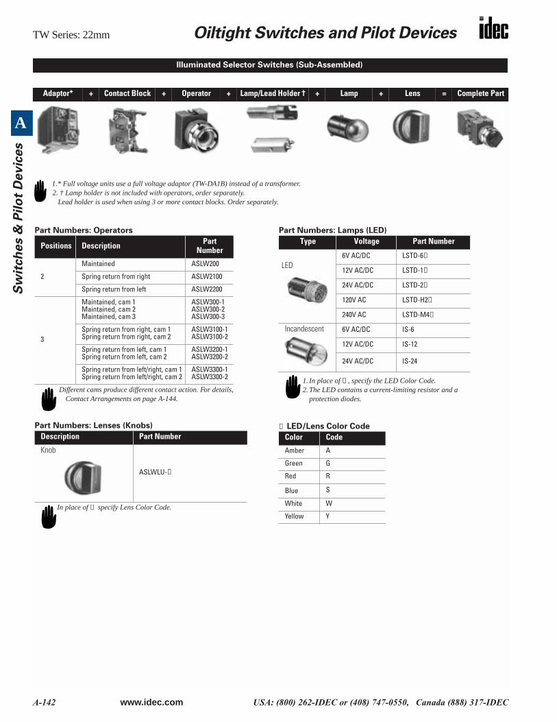
Adaptor* + Contact Block + Operator + Lamp/Lead Holder † + Lamp + Lens = Complete Part
Illuminated Selector Switches (Sub-Assembled)
1.* Full voltage units use a full voltage adaptor (TW-DA1B) instead of a transformer.2. † Lamp holder is not included with operators, order separately.
Lead holder is used when using 3 or more contact blocks. Order separately.
Part Numbers: Operators
Part Numbers: Lenses (Knobs)
Part Numbers: Lamps (LED)
➁ LED/Lens Color Code
Positions Description Part Number
2
Maintained ASLW200
Spring return from right ASLW2100
Spring return from left ASLW2200
3
Maintained, cam 1Maintained, cam 2Maintained, cam 3
ASLW300-1ASLW300-2ASLW300-3
Spring return from right, cam 1Spring return from right, cam 2
ASLW3100-1ASLW3100-2
Spring return from left, cam 1Spring return from left, cam 2
ASLW3200-1ASLW3200-2
Spring return from left/right, cam 1Spring return from left/right, cam 2
ASLW3300-1ASLW3300-2
Description Part Number
Knob
ASLWLU-➁
Different cams produce different contact action. For details,Contact Arrangements on page A-144.
In place of ➁ specify Lens Color Code.
Type Voltage Part Number
LED6V AC/DC LSTD-6➁
12V AC/DC LSTD-1➁
24V AC/DC LSTD-2➁
120V AC LSTD-H2➁
240V AC LSTD-M4➁
Incandescent 6V AC/DC IS-6
12V AC/DC IS-12
24V AC/DC IS-24
Color Code
Amber A
Green G
Red R
Blue S
White W
Yellow Y
1. In place of ➁ , specify the LED Color Code.2. The LED contains a current-limiting resistor and a
protection diodes.
Oiltight Switches and Pilot Devices TW Series: 22mm
www.idec.com USA: (800) 262-IDEC or (408) 747-0550, Canada (888) 317-IDEC A-143
A
Sw
itch
es &
Pilo
t Devic
es
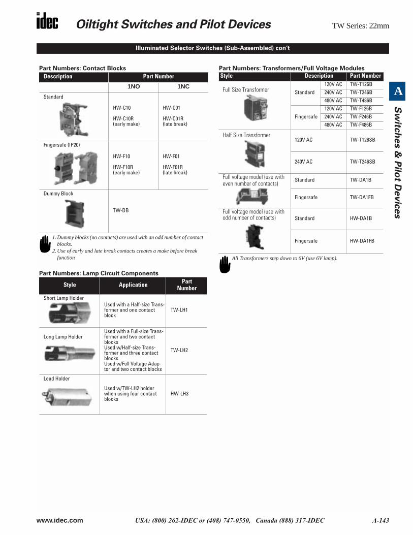
Illuminated Selector Switches (Sub-Assembled) con’t
Part Numbers: Contact Blocks
Part Numbers: Lamp Circuit Components
Part Numbers: Transformers/Full Voltage Modules
Description Part Number
1NO 1NC
Standard
HW-C10
HW-C10R(early make)
HW-C01
HW-C01R(late break)
Fingersafe (IP20)
HW-F10
HW-F10R(early make)
HW-F01
HW-F01R(late break)
Dummy Block
TW-DB
Style Application Part Number
Short Lamp HolderUsed with a Half-size Trans-former and one contact block
TW-LH1
Long Lamp HolderUsed with a Full-size Trans-former and two contact blocksUsed w/Half-size Trans-former and three contact blocksUsed w/Full Voltage Adap-tor and two contact blocks
TW-LH2
Lead Holder
Used w/TW-LH2 holder when using four contact blocks
HW-LH3
1. Dummy blocks (no contacts) are used with an odd number of contact blocks.
2. Use of early and late break contacts creates a make before break function
Style Description Part Number
Full Size Transformer Standard120V AC TW-T126B240V AC TW-T246B480V AC TW-T486B
Fingersafe120V AC TW-F126B240V AC TW-F246B480V AC TW-F486B
Half Size Transformer120V AC TW-T126SB
240V AC TW-T246SB
Full voltage model (use with even number of contacts)
Standard TW-DA1B
Fingersafe TW-DA1FB
Full voltage model (use with odd number of contacts) Standard HW-DA1B
Fingersafe HW-DA1FB
All Transformers step down to 6V (use 6V lamp).
TW Series: 22mm Oiltight Switches and Pilot Devices
A-144 www.idec.com USA: (800) 262-IDEC or (408) 747-0550, Canada (888) 317-IDEC
A
Sw
itch
es &
Pil
ot
Devic
es
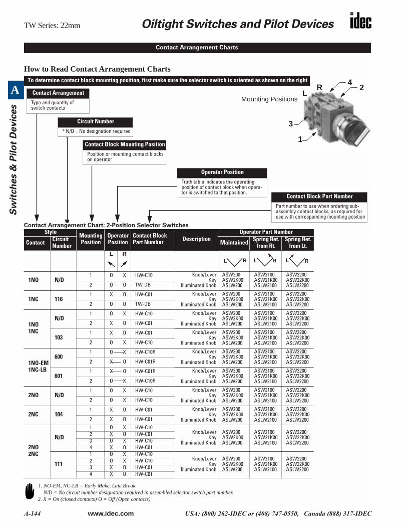
How to Read Contact Arrangement Charts
Contact Arrangement Chart: 2-Position Selector SwitchesStyle
MountingPosition
Operator Position
Contact Block Part Number Description
Operator Part Number
Contact CircuitNumber Maintained Spring Ret.
from Rt.Spring Ret.
from Lt.L R
1NO N/D1 O X HW-C10 Knob/Lever
KeyIlluminated Knob
ASW200ASW2K00ASLW200
ASW2100ASW21K00ASLW2100
ASW2200ASW22K00ASLW22002 O O TW-DB
1NC 1161 X O HW-C01 Knob/Lever
KeyIlluminated Knob
ASW200ASW2K00ASLW200
ASW2100ASW21K00ASLW2100
ASW2200ASW22K00ASLW22002 O O TW-DB
1NO1NC
N/D1 O X HW-C10 Knob/Lever
KeyIlluminated Knob
ASW200ASW2K00ASLW200
ASW2100ASW21K00ASLW2100
ASW2200ASW22K00ASLW22002 X O HW-C01
1031 X O HW-C01 Knob/Lever
KeyIlluminated Knob
ASW200ASW2K00ASLW200
ASW2100ASW21K00ASLW2100
ASW2200ASW22K00ASLW22002 O X HW-C10
1NO-EM1NC-LB
6001 O X HW-C10R Knob/Lever
KeyIlluminated Knob
ASW200ASW2K00ASLW200
ASW2100ASW21K00ASLW2100
ASW2200ASW22K00ASLW22002 X O HW-C01R
6011 X O HW-C01R Knob/Lever
KeyIlluminated Knob
ASW200ASW2K00ASLW200
ASW2100ASW21K00ASLW2100
ASW2200ASW22K00ASLW22002 O X HW-C10R
2NO N/D1 O X HW-C10 Knob/Lever
KeyIlluminated Knob
ASW200ASW2K00ASLW200
ASW2100ASW21K00ASLW2100
ASW2200ASW22K00ASLW22002 O X HW-C10
2NC 1041 X O HW-C01 Knob/Lever
KeyIlluminated Knob
ASW200ASW2K00ASLW200
ASW2100ASW21K00ASLW2100
ASW2200ASW22K00ASLW22002 X O HW-C01
2NO2NC
N/D
1 O X HW-C10Knob/Lever
KeyIlluminated Knob
ASW200ASW2K00ASLW200
ASW2100ASW21K00ASLW2100
ASW2200ASW22K00ASLW2200
2 X O HW-C013 O X HW-C104 X O HW-C01
111
1 O X HW-C10Knob/Lever
KeyIlluminated Knob
ASW200ASW2K00ASLW200
ASW2100ASW21K00ASLW2100
ASW2200ASW22K00ASLW2200
2 O X HW-C103 X O HW-C014 X O HW-C01
Contact Arrangement Charts
2
3
Mounting Positions
4
Contact Block Part Number
Part number to use when ordering sub-assembly contact blocks, as required for use with corresponding mounting position
Contact Block Mounting Position
Position or mounting contact blocks on operator
Operator Position
Truth table indicates the operating position of contact block when opera-tor is switched to that position.
Contact Arrangement
Type and quantity of switch contacts
To determine contact block mounting position, first make sure the selector switch is oriented as shown on the right
LR
1
Circuit Number
* N/D = No designation required
L R L R L R
1. NO-EM, NC-LB = Early Make, Late Break.N/D = No circuit number designation required in assembled selector switch part number.
2. X = On (closed contacts) O = Off (Open contacts)
Oiltight Switches and Pilot Devices TW Series: 22mm
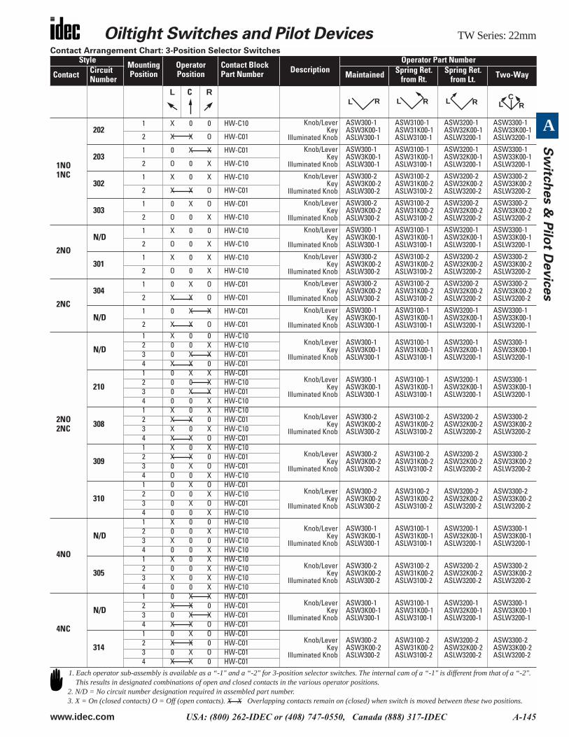
www.idec.com USA: (800) 262-IDEC or (408) 747-0550, Canada (888) 317-IDEC A-145
A
Sw
itch
es &
Pilo
t Devic
es
Contact Arrangement Chart: 3-Position Selector SwitchesStyle
MountingPosition
Operator Position
Contact Block Part Number Description
Operator Part Number
Contact CircuitNumber Maintained Spring Ret.
from Rt.Spring Ret.
from Lt. Two-Way
L C R
1NO1NC
2021 X 0 0 HW-C10 Knob/Lever
KeyIlluminated Knob
ASW300-1ASW3K00-1ASLW300-1
ASW3100-1ASW31K00-1ASLW3100-1
ASW3200-1ASW32K00-1ASLW3200-1
ASW3300-1ASW33K00-1ASLW3200-12 X X O HW-C01
2031 0 X X HW-C01 Knob/Lever
KeyIlluminated Knob
ASW300-1ASW3K00-1ASLW300-1
ASW3100-1ASW31K00-1ASLW3100-1
ASW3200-1ASW32K00-1ASLW3200-1
ASW3300-1ASW33K00-1ASLW3200-12 O 0 X HW-C10
3021 X 0 X HW-C10 Knob/Lever
KeyIlluminated Knob
ASW300-2ASW3K00-2ASLW300-2
ASW3100-2ASW31K00-2ASLW3100-2
ASW3200-2ASW32K00-2ASLW3200-2
ASW3300-2ASW33K00-2ASLW3200-22 X X O HW-C01
3031 0 X O HW-C01 Knob/Lever
KeyIlluminated Knob
ASW300-2ASW3K00-2ASLW300-2
ASW3100-2ASW31K00-2ASLW3100-2
ASW3200-2ASW32K00-2ASLW3200-2
ASW3300-2ASW33K00-2ASLW3200-22 O 0 X HW-C10
2NO
N/D1 X 0 0 HW-C10 Knob/Lever
KeyIlluminated Knob
ASW300-1ASW3K00-1ASLW300-1
ASW3100-1ASW31K00-1ASLW3100-1
ASW3200-1ASW32K00-1ASLW3200-1
ASW3300-1ASW33K00-1ASLW3200-12 O 0 X HW-C10
3011 X 0 X HW-C10 Knob/Lever
KeyIlluminated Knob
ASW300-2ASW3K00-2ASLW300-2
ASW3100-2ASW31K00-2ASLW3100-2
ASW3200-2ASW32K00-2ASLW3200-2
ASW3300-2ASW33K00-2ASLW3200-22 O 0 X HW-C10
2NC
3041 0 X O HW-C01 Knob/Lever
KeyIlluminated Knob
ASW300-2ASW3K00-2ASLW300-2
ASW3100-2ASW31K00-2ASLW3100-2
ASW3200-2ASW32K00-2ASLW3200-2
ASW3300-2ASW33K00-2ASLW3200-22 X X O HW-C01
N/D1 0 X X HW-C01 Knob/Lever
KeyIlluminated Knob
ASW300-1ASW3K00-1ASLW300-1
ASW3100-1ASW31K00-1ASLW3100-1
ASW3200-1ASW32K00-1ASLW3200-1
ASW3300-1ASW33K00-1ASLW3200-12 X X O HW-C01
2NO2NC
N/D
1 X 0 0 HW-C10Knob/Lever
KeyIlluminated Knob
ASW300-1ASW3K00-1ASLW300-1
ASW3100-1ASW31K00-1ASLW3100-1
ASW3200-1ASW32K00-1ASLW3200-1
ASW3300-1ASW33K00-1ASLW3200-1
2 0 0 X HW-C103 0 X X HW-C014 X X 0 HW-C01
210
1 0 X X HW-C01Knob/Lever
KeyIlluminated Knob
ASW300-1ASW3K00-1ASLW300-1
ASW3100-1ASW31K00-1ASLW3100-1
ASW3200-1ASW32K00-1ASLW3200-1
ASW3300-1ASW33K00-1ASLW3200-1
2 0 0 X HW-C103 0 X X HW-C014 0 0 X HW-C10
308
1 X 0 X HW-C10Knob/Lever
KeyIlluminated Knob
ASW300-2ASW3K00-2ASLW300-2
ASW3100-2ASW31K00-2ASLW3100-2
ASW3200-2ASW32K00-2ASLW3200-2
ASW3300-2ASW33K00-2ASLW3200-2
2 X X 0 HW-C013 X 0 X HW-C104 X X O HW-C01
309
1 X 0 X HW-C10Knob/Lever
KeyIlluminated Knob
ASW300-2ASW3K00-2ASLW300-2
ASW3100-2ASW31K00-2ASLW3100-2
ASW3200-2ASW32K00-2ASLW3200-2
ASW3300-2ASW33K00-2ASLW3200-2
2 X X 0 HW-C013 0 X O HW-C014 O 0 X HW-C10
310
1 0 X O HW-C01Knob/Lever
KeyIlluminated Knob
ASW300-2ASW3K00-2ASLW300-2
ASW3100-2ASW31K00-2ASLW3100-2
ASW3200-2ASW32K00-2ASLW3200-2
ASW3300-2ASW33K00-2ASLW3200-2
2 O 0 X HW-C103 0 X O HW-C014 0 0 X HW-C10
4NO
N/D
1 X 0 0 HW-C10Knob/Lever
KeyIlluminated Knob
ASW300-1ASW3K00-1ASLW300-1
ASW3100-1ASW31K00-1ASLW3100-1
ASW3200-1ASW32K00-1ASLW3200-1
ASW3300-1ASW33K00-1ASLW3200-1
2 0 0 X HW-C103 X 0 0 HW-C104 0 0 X HW-C10
305
1 X 0 X HW-C10Knob/Lever
KeyIlluminated Knob
ASW300-2ASW3K00-2ASLW300-2
ASW3100-2ASW31K00-2ASLW3100-2
ASW3200-2ASW32K00-2ASLW3200-2
ASW3300-2ASW33K00-2ASLW3200-2
2 0 0 X HW-C103 X 0 X HW-C104 0 0 X HW-C10
4NC
N/D
1 0 X X HW-C01Knob/Lever
KeyIlluminated Knob
ASW300-1ASW3K00-1ASLW300-1
ASW3100-1ASW31K00-1ASLW3100-1
ASW3200-1ASW32K00-1ASLW3200-1
ASW3300-1ASW33K00-1ASLW3200-1
2 X X 0 HW-C013 0 X X HW-C014 X X O HW-C01
314
1 0 X O HW-C01Knob/Lever
KeyIlluminated Knob
ASW300-2ASW3K00-2ASLW300-2
ASW3100-2ASW31K00-2ASLW3100-2
ASW3200-2ASW32K00-2ASLW3200-2
ASW3300-2ASW33K00-2ASLW3200-2
2 X X 0 HW-C013 0 X O HW-C014 X X 0 HW-C01
L R L R L R LC
R
1. Each operator sub-assembly is available as a “-1" and a “-2" for 3-position selector switches. The internal cam of a “-1" is different from that of a “-2". This results in designated combinations of open and closed contacts in the various operator positions.
2. N/D = No circuit number designation required in assembled part number.3. X = On (closed contacts) O = Off (open contacts). X X Overlapping contacts remain on (closed) when switch is moved between these two positions.
TW Series: 22mm Oiltight Switches and Pilot Devices
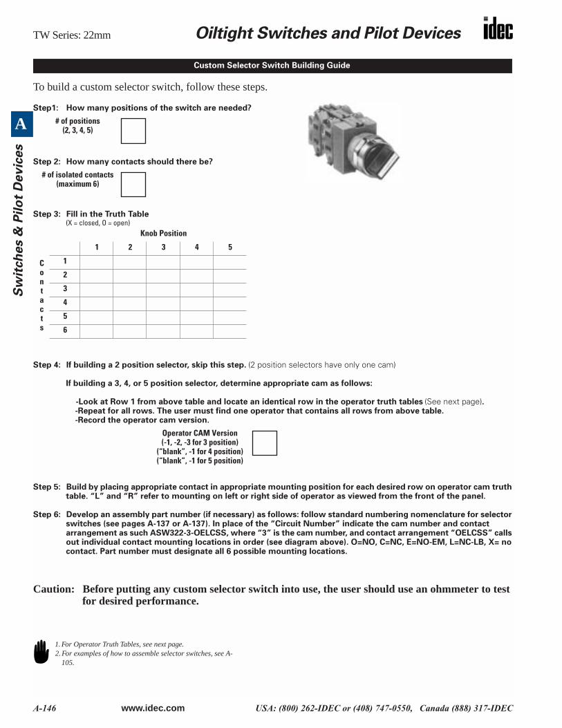
A-146 www.idec.com USA: (800) 262-IDEC or (408) 747-0550, Canada (888) 317-IDEC
A
Sw
itch
es &
Pil
ot
Devic
es
To build a custom selector switch, follow these steps.
Step1: How many positions of the switch are needed?
Step 2: How many contacts should there be?
Step 3: Fill in the Truth Table (X = closed, O = open)
Step 4: If building a 2 position selector, skip this step. (2 position selectors have only one cam)
If building a 3, 4, or 5 position selector, determine appropriate cam as follows:
-Look at Row 1 from above table and locate an identical row in the operator truth tables (See next page). -Repeat for all rows. The user must find one operator that contains all rows from above table.-Record the operator cam version.
Step 5: Build by placing appropriate contact in appropriate mounting position for each desired row on operator cam truth table. “L” and “R” refer to mounting on left or right side of operator as viewed from the front of the panel.
Step 6: Develop an assembly part number (if necessary) as follows: follow standard numbering nomenclature for selector switches (see pages A-137 or A-137). In place of the “Circuit Number” indicate the cam number and contact arrangement as such ASW322-3-OELCSS, where “3” is the cam number, and contact arrangement “OELCSS” calls out individual contact mounting locations in order (see diagram above). O=NO, C=NC, E=NO-EM, L=NC-LB, X= no contact. Part number must designate all 6 possible mounting locations.
Caution: Before putting any custom selector switch into use, the user should use an ohmmeter to test for desired performance.
Knob Position
1 2 3 4 5
Contacts
1
2
3
4
5
6
Custom Selector Switch Building Guide
# of positions(2, 3, 4, 5)
# of isolated contacts(maximum 6)
Operator CAM Version(-1, -2, -3 for 3 position)
(“blank”, -1 for 4 position)(“blank”, -1 for 5 position)
1. For Operator Truth Tables, see next page.2. For examples of how to assemble selector switches, see A-
105.
Oiltight Switches and Pilot Devices TW Series: 22mm
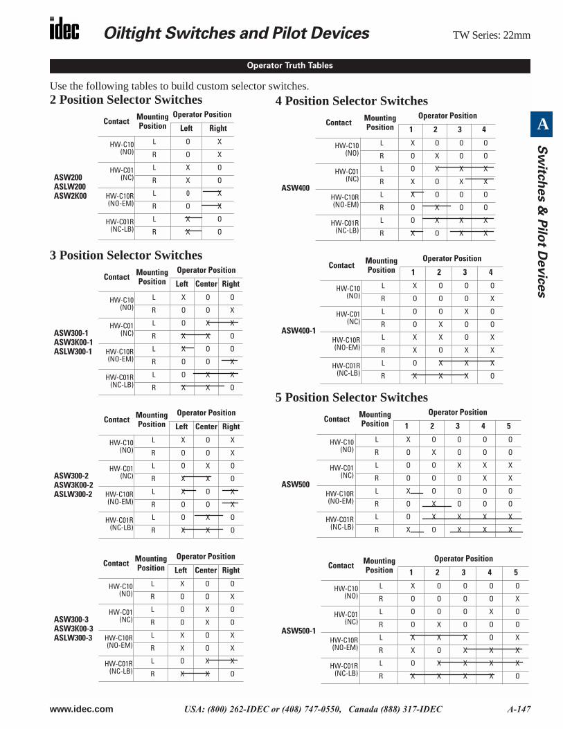
www.idec.com USA: (800) 262-IDEC or (408) 747-0550, Canada (888) 317-IDEC A-147
A
Sw
itch
es &
Pilo
t Devic
es
Use the following tables to build custom selector switches.2 Position Selector Switches
3 Position Selector Switches
Contact Mounting Position
Operator Position
Left Right
ASW200ASLW200ASW2K00
HW-C10(NO)
L O X
R O X
HW-C01(NC)
L X O
R X O
HW-C10R(NO-EM)
L 0 X
R O X
HW-C01R(NC-LB)
L X O
R X O
Contact Mounting Position
Operator Position
Left Center Right
ASW300-1ASW3K00-1ASLW300-1
HW-C10(NO)
L X O O
R O O X
HW-C01(NC)
L O X X
R X X O
HW-C10R(NO-EM)
L X O O
R O O X
HW-C01R(NC-LB)
L O X X
R X X O
Contact Mounting Position
Operator Position
Left Center Right
ASW300-2ASW3K00-2ASLW300-2
HW-C10(NO)
L X O X
R O O X
HW-C01(NC)
L O X O
R X X O
HW-C10R(NO-EM)
L X O X
R O O X
HW-C01R(NC-LB)
L O X O
R X X O
Contact Mounting Position
Operator Position
Left Center Right
ASW300-3ASW3K00-3ASLW300-3
HW-C10(NO)
L X O O
R O O X
HW-C01(NC)
L O X O
R O X O
HW-C10R(NO-EM)
L X O X
R X O X
HW-C01R(NC-LB)
L O X X
R X X O
Operator Truth Tables
4 Position Selector Switches
5 Position Selector Switches
Contact Mounting Position
Operator Position
1 2 3 4
ASW400
HW-C10(NO)
L X O O O
R O X O O
HW-C01(NC)
L O X X X
R X O X X
HW-C10R(NO-EM)
L X O O O
R O X O O
HW-C01R(NC-LB)
L O X X X
R X O X X
Contact Mounting Position
Operator Position
1 2 3 4
ASW400-1
HW-C10(NO)
L X O O O
R O O O X
HW-C01(NC)
L O O X O
R O X O O
HW-C10R(NO-EM)
L X X O X
R X O X X
HW-C01R(NC-LB)
L O X X X
R X X X O
Contact Mounting Position
Operator Position
1 2 3 4 5
ASW500
HW-C10(NO)
L X O O O O
R O X O O O
HW-C01(NC)
L O O X X X
R O O O X X
HW-C10R(NO-EM)
L X O O O O
R O X O O O
HW-C01R(NC-LB)
L O X X X X
R X O X X X
Contact Mounting Position
Operator Position
1 2 3 4 5
ASW500-1
HW-C10(NO)
L X O O O O
R O O O O X
HW-C01(NC)
L O O O X O
R O X O O O
HW-C10R(NO-EM)
L X X X O X
R X O X X X
HW-C01R(NC-LB)
L O X X X X
R X X X X O
TW Series: 22mm Oiltight Switches and Pilot Devices
A-148 www.idec.com USA: (800) 262-IDEC or (408) 747-0550, Canada (888) 317-IDEC
A
Sw
itch
es &
Pil
ot
Devic
es
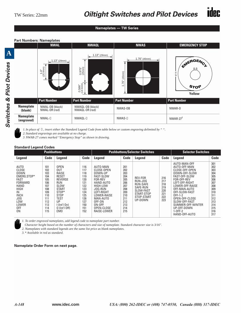
Part Numbers: Nameplates
Standard Legend Codes
Nameplate Order Form on next page.
NWAL NWAQL NWAS EMERGENCY STOP
Part Number Part Number Part Number Part Number
Nameplate (blank)
NWAL-OB (black)NWAL-OR (red)
NWAQL-OB (black)NWAQL-OR (red) NWAS-OB NWAR-O
Nameplate (engraved) NWAL-➀ NWAQL-➀ NWAS-➀ NWAR-27†
Pushbuttons Pushbuttons/Selector Switches Selector Switches
Legend Code Legend Code Legend Code Legend Code Legend Code
AUTOCLOSEDOWNEMERG.STOP*FASTFORWARDHANDHIGHININCHJOGLOWLOWEROFFON
101102103104105106107108109110111112113114115
OPENOUTRAISERESETREVERSERUNSLOWSTARTSTOP*STOPTESTUPI (Int’l On)O (Int’l Off)EMO
116117118119120121122123124125126127150151152
AUTO-MANCLOSE-OPENDOWN-UPFAST-SLOWFOR-REVHAND-AUTOHIGH-LOWJOG-RUNLEFT-RIGHTLOWER-RAISEMAN-AUTOOFF-ONON-OFFOPEN-CLOSERAISE-LOWER
201202203204205206207208209210211212213214215
REV-FORRUN-JOGRUN-SAFESAFE-RUNSLOW-FASTSTART-STOPSTOP-STARTUP-DOWN
216217218219220221222223
AUTO-MAN-OFFAUTO-OFF-MANCLOSE-OFF-OPENDOWN-OFF-SLOWFAST-OFF-SLOWFOR-OFF-REVLEFT-OFF-RIGHTLOWER-OFF-RAISEOFF-MAN-AUTOOFF-SLOW-FASTOFF-1-2OPEN-OFF-CLOSESLOW-OFF-FASTSUMMER-OFF-WINTERUP-OFF-DOWN1-OFF-2HAND-OFF-AUTO
301302303304305306307308309310311312313314315316317
Nameplates — TW Series
1.13" (29mm)
1.0"
(25.
4mm
)
1.13" (29mm)
0.97
5"(2
5mm
)
0.56
6"(1
4.5m
m)
1.76" (45mm)
1.76
" (4
5mm
)
EMERGENC
Y
STOP
Ø 7
0
Yellow
1. In place of ➀ , insert either the Standard Legend Code from table below or custom engraving delimited by “ “.2. Standard engravings are available at no charge. 3 NWAR-27 comes marked “Emergency Stop” as shown in drawing.
1. To order engraved nameplates, add legend code to nameplate part number.Character height based on the number of characters and size of nameplate. Standard character size is 3/16".
2. Nameplates with standard legends are the same list price as blank nameplates. 3. * Available in red as standard.
Oiltight Switches and Pilot Devices TW Series: 22mm
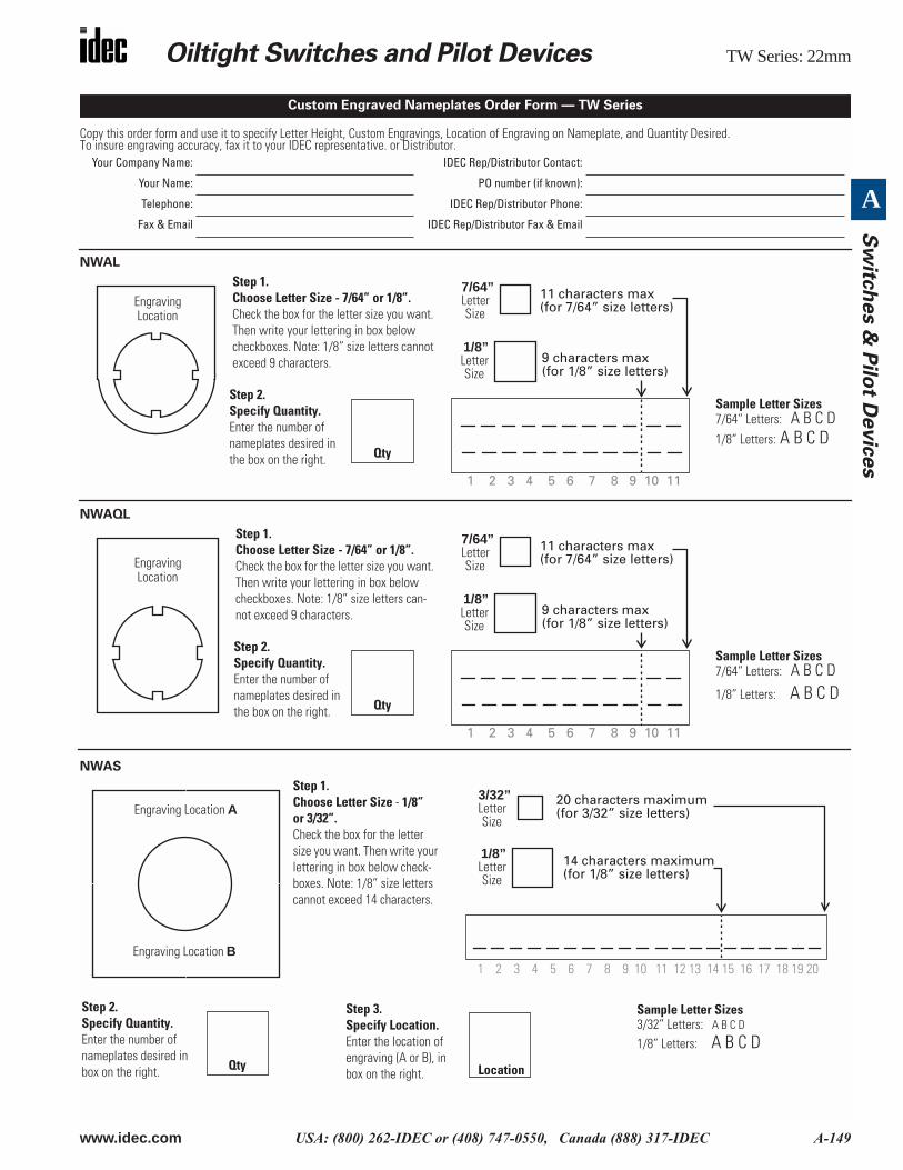
www.idec.com USA: (800) 262-IDEC or (408) 747-0550, Canada (888) 317-IDEC A-149
A
Sw
itch
es &
Pilo
t Devic
es
Copy this order form and use it to specify Letter Height, Custom Engravings, Location of Engraving on Nameplate, and Quantity Desired. To insure engraving accuracy, fax it to your IDEC representative. or Distributor.
NWAL
NWAQL
NWAS
Your Company Name: IDEC Rep/Distributor Contact:
Your Name: PO number (if known):
Telephone: IDEC Rep/Distributor Phone:
Fax & Email IDEC Rep/Distributor Fax & Email
Custom Engraved Nameplates Order Form — TW Series
Step 1. Choose Letter Size - 7/64” or 1/8”.Check the box for the letter size you want. Then write your lettering in box below checkboxes. Note: 1/8” size letters cannot exceed 9 characters.
Engraving Location
Step 2. Specify Quantity. Enter the number of nameplates desired in the box on the right. Qty
Sample Letter Sizes7/64” Letters: A B C D1/8” Letters: A B C D
1/8”LetterSize
7/64”LetterSize
9 characters max (for 1/8” size letters)
11 characters max (for 7/64” size letters)
1 2 3 4 5 6 7 8 9 10 11
Step 1. Choose Letter Size - 7/64” or 1/8”.Check the box for the letter size you want. Then write your lettering in box below checkboxes. Note: 1/8” size letters can-not exceed 9 characters.
Engraving Location
Step 2. Specify Quantity. Enter the number of nameplates desired in the box on the right. Qty
Sample Letter Sizes7/64” Letters: A B C D1/8” Letters: A B C D
1/8”LetterSize
7/64”LetterSize
9 characters max (for 1/8” size letters)
11 characters max (for 7/64” size letters)
1 2 3 4 5 6 7 8 9 10 11
Step 1. Choose Letter Size - 1/8” or 3/32”. Check the box for the letter size you want. Then write your lettering in box below check-boxes. Note: 1/8” size letters cannot exceed 14 characters.
Engraving Location A
Engraving Location B
Step 2. Specify Quantity. Enter the number of nameplates desired in box on the right. Qty
Step 3. Specify Location. Enter the location of engraving (A or B), in box on the right. Location
Sample Letter Sizes3/32” Letters: A B C D
1/8” Letters: A B C D
1/8”LetterSize
3/32”LetterSize
14 characters maximum
1 2 3 4 5 6 7 8 9 10 11 12 13 14 15 16 17 18 19 20
20 characters maximum(for 3/32” size letters)
(for 1/8” size letters)
TW Series: 22mm Oiltight Switches and Pilot Devices
A-150 www.idec.com USA: (800) 262-IDEC or (408) 747-0550, Canada (888) 317-IDEC
A
Sw
itch
es &
Pil
ot
Devic
es
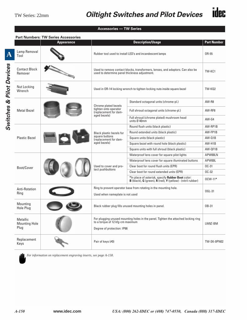
Part Numbers: TW Series Accessories
Appearance Description/Usage Part Number
Lamp Removal Tool Rubber tool used to install LED’s and incandescent lamps OR-55
Contact Block Remover
Used to remove contact blocks, transformers, lenses, and adaptors. Can also be used to determine panel thickness adjustment. TW-KC1
Nut Locking Wrench Used in OR-14 locking wrench to tighten locking nuts inside square bezel TW-KQ2
Metal BezelChrome plated bezels tighten onto operator(replacement for dam-aged bezels)
Standard octagonal units (chrome-pl.) AW-R8
Full shroud octagonal units (chrome-pl.) AW-RF8
Full shroud (chrome plated) mushroom head units Ø 40mm AW-G4
Plastic BezelBlack plastic bezels for square buttons(replacement for dam-aged bezels)
Round flush units (black plastic) AW-RP1B
Round extended units (black plastic) AW-FP1B
Square units (black plastic) AW-Q1B
Square bezel with round hole (black plastic) AW-H1B
Square units with full shroud (black plastic) AW-QF1B
Boot/Cover Used to cover and pro-tect pushbuttons
Waterproof lens cover for square pilot lights APW00LN
Waterproof lens cover for square illuminated buttons APW00L
Clear boot for round flush units (EPR) OC-31
Clear boot for round extended units (EPR) OC-32
*In place of asterisk, specify Rubber Boot color:B (black), G (green), R (red), Y (yellow) - (nitril rubber) OCW-11*
Anti-Rotation Ring
Ring to prevent operator base from rotating in the mounting hole.
Used when nameplate is not usedOGL-31
Mounting Hole Plug Black rubber plug fills unused mounting holes in panel. OB-31
Metallic Mounting Hole Plug
For plugging unused mounting holes in the panel. Tighten the attached locking ring to a torque of 12 kfg-cm maximum
Degree of protection: IP66LW9Z-BM
Replacement Keys Pair of keys (#0) TW-SK-0PN02
Accessories — TW Series
For information on replacement engraving inserts, see page A-158.
Oiltight Switches and Pilot Devices TW Series: 22mm
www.idec.com USA: (800) 262-IDEC or (408) 747-0550, Canada (888) 317-IDEC A-151
A
Sw
itch
es &
Pilo
t Devic
es
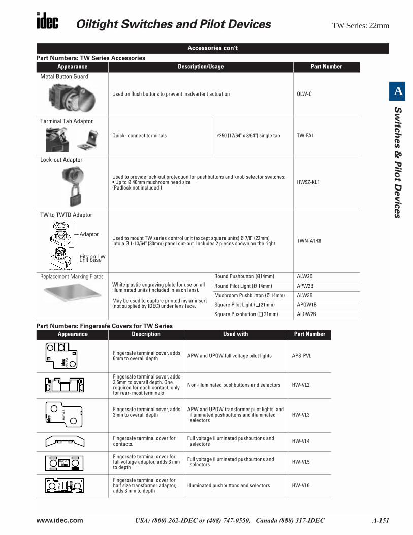
Part Numbers: TW Series Accessories
Part Numbers: Fingersafe Covers for TW Series
Appearance Description/Usage Part Number
Metal Button Guard
Used on flush buttons to prevent inadvertent actuation OLW-C
Terminal Tab Adaptor
Quick- connect terminals #250 (17/64" x 3/64") single tab TW-FA1
Lock-out Adaptor
Used to provide lock-out protection for pushbuttons and knob selector switches:• Up to Ø 40mm mushroom head size(Padlock not included.)
HW9Z-KL1
TW to TWTD Adaptor
Used to mount TW series control unit (except square units) Ø 7/8" (22mm)into a Ø 1-13/64" (30mm) panel cut-out. Includes 2 pieces shown on the right TWN-A1R8
Replacement Marking PlatesWhite plastic engraving plate for use on all illuminated units (included in each lens).
May be used to capture printed mylar insert (not supplied by IDEC) under lens face.
Round Pushbutton (Ø14mm) ALW2B
Round Pilot Light (Ø 14mm) APW2B
Mushroom Pushbutton (Ø 14mm) ALW3B
Square Pilot Light ( 21mm) APQW1B
Square Pushbutton ( 21mm) ALQW2B
Appearance Description Used with Part Number
Fingersafe terminal cover, adds 6mm to overall depth APW and UPQW full voltage pilot lights APS-PVL
Fingersafe terminal cover, adds 3.5mm to overall depth. One required for each contact, only for rear- most terminals
Non-illuminated pushbuttons and selectors HW-VL2
Fingersafe terminal cover, adds 3mm to overall depth
APW and UPQW transformer pilot lights, and illuminated pushbuttons and illuminated selectors
HW-VL3
Fingersafe terminal cover for contacts.
Full voltage illuminated pushbuttons and selectors HW-VL4
Fingersafe terminal cover for full voltage adaptor, adds 3 mm to depth
Full voltage illuminated pushbuttons and selectors HW-VL5
Fingersafe terminal cover for half size transformer adaptor, adds 3 mm to depth
Illuminated pushbuttons and selectors HW-VL6
Accessories con’t
Adaptor
Fits on TWunit base
AP
S-P
VL
HW
-VL3
HW VL5
HW
VL6
TW Series: 22mm Oiltight Switches and Pilot Devices
A-152 www.idec.com USA: (800) 262-IDEC or (408) 747-0550, Canada (888) 317-IDEC
A
Sw
itch
es &
Pil
ot
Devic
es
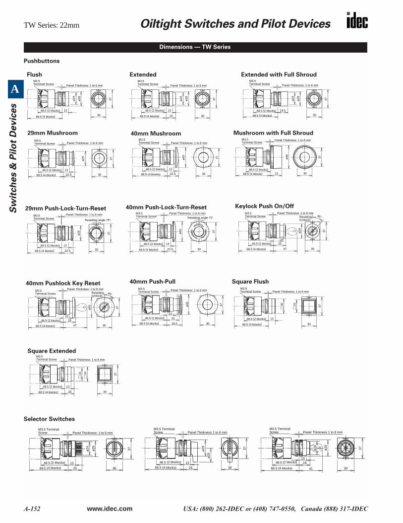
Pushbuttons
Selector Switches
Dimensions — TW Series
M3.5Terminal Screw
68.5 (4 blocks)
48.5 (2 blocks)
Panel Thickness: 1 to 6 mm
30
37ø29
ø24
13 13
19 30
37ø29
ø24
M3.5Terminal Screw
68.5 (4 blocks)
48.5 (2 blocks)
Panel Thickness: 1 to 6 mm
ø29
30
37ø24
19.5
M3.5Terminal Screw
68.5 (4 blocks)
48.5 (2 blocks)
Panel Thickness: 1 to 6 mm
13
22.5 30
37ø29
M3.5Terminal Screw
68.5 (4 blocks)
48.5 (2 blocks)
Panel Thickness: 1 to 6 mm
13
22.5
ø40
30
37
M3.5Terminal Screw
68.5 (4 blocks)
48.5 (2 blocks)
Panel Thickness: 1 to 6 mm
30
37ø46
23
M3.5Terminal Screw
68.5 (4 blocks)48.5 (2 blocks)
Panel Thickness: 1 to 6 mm
Resetting angle 75°
30
37
13
22.5
ø29
M3.5Terminal Screw
68.5 (4 blocks)
48.5 (2 blocks)
Panel Thickness: 1 to 6 mm
30
37
13
22.5
ø40
Resetting angle 75°M3.5Terminal Screw
68.5 (4 blocks)
48.5 (2 blocks)
Panel Thickness: 1 to 6 mmResetting(Unlock)
37
25
47
13
ø29
45°
30
M3.5Terminal Screw
68.5 (4 blocks)
48.5 (2 blocks)
Panel Thickness: 1 to 6 mm
Resetting(Unlock)
37
25
47
13
45°
30
ø40
M3.5Terminal Screw
68.5 (4 blocks)
48.5 (2 blocks)
Panel Thickness: 1 to 6 mm
3713
30
30 25
M3.5Terminal Screw
68.5 (4 blocks)
48.5 (2 blocks)
Panel Thickness: 1 to 6 mm
37
25
13
30
ø40
30.5
M3.5Terminal Screw
68.5 (4 blocks)
48.5 (2 blocks)
Panel Thickness: 1 to 6 mm
37
13
30
30
20
25
M3.5Terminal Screw
68.5 (4 blocks)
48.5 (2 blocks)
Panel Thickness: 1 to 6 mm
Flush Extended Extended with Full Shroud
29mm Mushroom 40mm Mushroom Mushroom with Full Shroud
29mm Push-Lock-Turn-Reset 40mm Push-Lock-Turn-Reset Keylock Push On/Off
40mm Pushlock Key Reset 40mm Push-Pull Square Flush
Square Extended
M3.5 TerminalScrew
48.5 (2 blocks)
68.5 (4 blocks)
Panel Thickness: 1 to 6 mm
37
25
13
30
ø24 ø29
M3.5 TerminalScrew
48.5 (2 blocks)
68.5 (4 blocks)
Panel Thickness 1 to 6 mm
37
13
30
ø29
ø25
25
M3.5 TerminalScrew
48.5 (2 blocks)
68.5 (4 blocks)
Panel Thickness 1 to 6 mm
37
13
30
ø29
19
41
ø24
Oiltight Switches and Pilot Devices TW Series: 22mm
www.idec.com USA: (800) 262-IDEC or (408) 747-0550, Canada (888) 317-IDEC A-153
A
Sw
itch
es &
Pilo
t Devic
es
IIlluminated Pushbuttons
Dimensions con’t
Marking Plate: ø15.5 mm
Panel Thickness: 1 to 6 mm
13
19 30
ø24
ø29 37
Marking Plate: ø15.5 mm
Panel Thickness: 1 to 6 mm
30
ø24
ø29 37
20
30
37
20
13
25 30
Marking Plate: 21 mm
Panel Thickness: 1 to 6 mmResetting Angle: 75°
30
37
13
22.5ø
29
Marking Plate: ø13.9 mm
Panel Thickness: 1 to 6 mm
Illuminated Pushbuttons Dimension A Dimension B
Extended (Same for Square)w/Full Shroud
0.741" (19mm)
0.761" (19.5mm)Ø 0.936" (Ø24mm) 0.975" ( 25mm)
Ø 1.13" (29mm) MushroomØ 1.56" (40mm) Mushroom, Pushlock Turn Reset, Push-Pull
0.858" (22mm)0.858" (22mm)*0.936" (24mm)† 0.975" (25mm)
Ø 1.13" (29mm)Ø 1.56" (40mm)Ø 1.56" (40mm)Ø 1.56" (40mm)
1. * Dimension when operator is in reset position.2. † Dimension when operator is in pull position.
Resetting angle: 75°
30
37
13
22.5
ø40
Marking Plate: ø13.9 mm
Panel Thickness: 1 to 6 mm
30
3713
ø29
22.5
Marking Plate: ø13.9 mm
Panel Thickness: 1 to 6 mm
Marking Plate: ø13.9 mm
Panel Thickness: 1 to 6 mm
30
37
25
13
ø40
30.5
X2X1
Panel Thickness: 1 to 6 mmM3.5 Terminal Screw
48.5
X2
X1M3.5 Terminal Screw Panel Thickness: 1 to 6 mm
86.5
X2
X1
64.5
Panel Thickness: 1 to 6 mm
X1
X2
63.5
M3.5 Terminal ScrewPanel Thickness: 1 to 6 mm
106.5
M3.5 Terminal Screw Panel Thickness: 1 to 6 mm
X2
X1
X2
X1
X2
X1
68.5
Panel Thickness: 1 to 6 m
X2X1
X2X1
68.5
M3.5 Terminal Screw Panel Thickness: 1 to 6 mm
83.5
M3.5 Terminal Screw Panel Thickness: 1 to 6 mm
84.5
M3.5 Terminal Screw
Panel Thickness:
Extended Extended with Full Shroud
Square Extended 29mm Push-Turn Reset
40mm Push-Turn Reset Mushroom Push-Pull
TW Series: 22mm Oiltight Switches and Pilot Devices
A-154 www.idec.com USA: (800) 262-IDEC or (408) 747-0550, Canada (888) 317-IDEC
A
Sw
itch
es &
Pil
ot
Devic
es
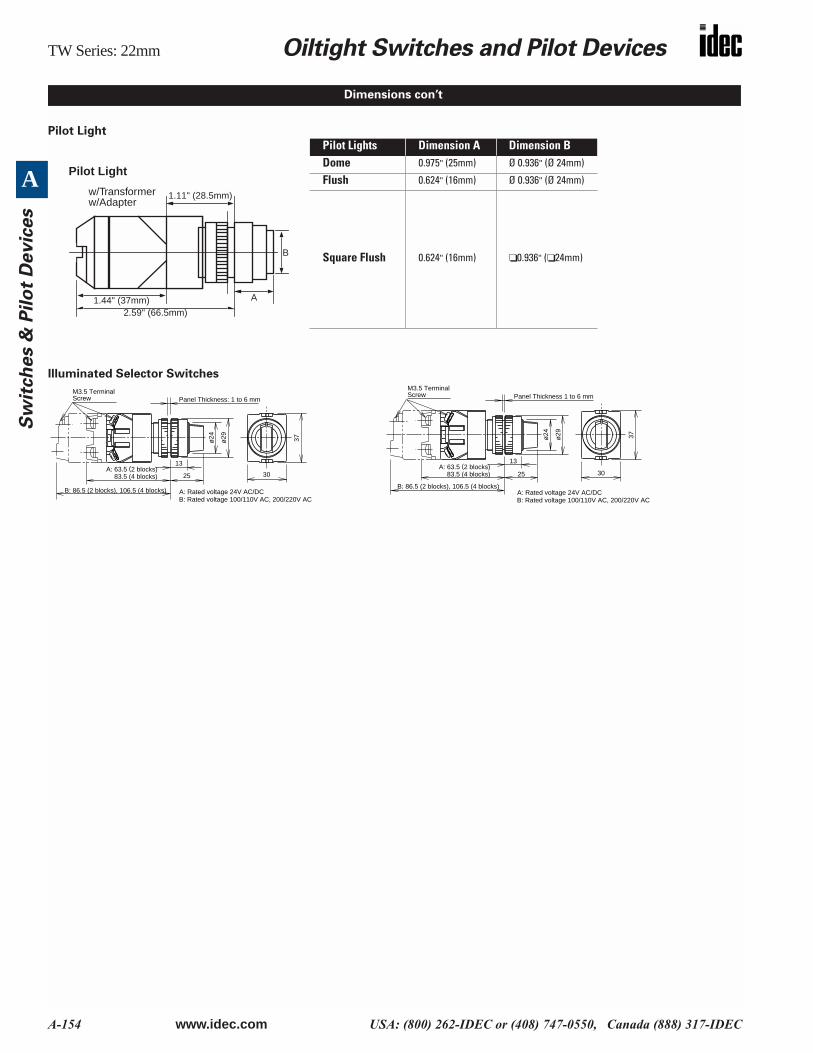
Pilot Light
Illuminated Selector Switches
Pilot Lights Dimension A Dimension BDome 0.975" (25mm) Ø 0.936" (Ø 24mm)
Flush 0.624" (16mm) Ø 0.936" (Ø 24mm)
Square Flush 0.624" (16mm) 0.936" ( 24mm)
Dimensions con’t
1.11" (28.5mm)
1.44" (37mm)2.59" (66.5mm)
A
B
Pilot Light
w/Transformerw/Adapter
A: Rated voltage 24V AC/DCB: Rated voltage 100/110V AC, 200/220V AC
M3.5 TerminalScrew
83.5 (4 blocks)
B: 86.5 (2 blocks), 106.5 (4 blocks)
A: 63.5 (2 blocks)
Panel Thickness: 1 to 6 mm
13
25
ø24
ø29
30
37
13
25
ø24
ø29
30
37
M3.5 TerminalScrew Panel Thickness 1 to 6 mm
A: Rated voltage 24V AC/DCB: Rated voltage 100/110V AC, 200/220V AC
B: 86.5 (2 blocks), 106.5 (4 blocks)
83.5 (4 blocks)A: 63.5 (2 blocks)
Oiltight Switches and Pilot Devices TW Series: 22mm
www.idec.com USA: (800) 262-IDEC or (408) 747-0550, Canada (888) 317-IDEC A-155
A
Sw
itch
es &
Pilo
t Devic
es
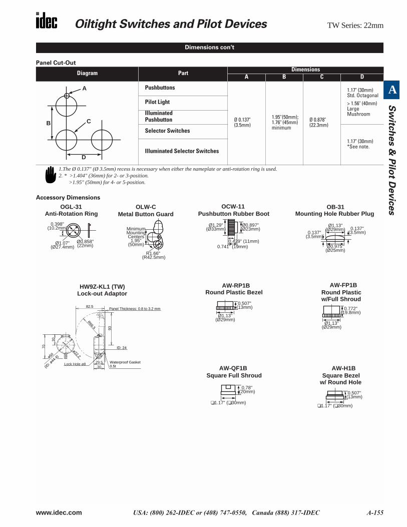
Panel Cut-Out
Accessory Dimensions
Diagram PartDimensions
A B C D
Pushbuttons
Ø 0.137" (3.5mm)
1.95" (50mm); 1.76" (45mm) minimum
Ø 0.878" (22.3mm)
1.17" (30mm)Std. Octagonal> 1.56" (40mm)Large Mushroom
Pilot Light
Illuminated Pushbutton
Selector Switches
1.17" (30mm)*See note.
Illuminated Selector Switches
A
B
D
C
1.The Ø 0.137" (Ø 3.5mm) recess is necessary when either the nameplate or anti-rotation ring is used.2. * >1.404" (36mm) for 2- or 3-position.
>1.95" (50mm) for 4- or 5-position.
0.507"(13mm)
Ø1.13"(Ø29mm)
AW-RP1BRound Plastic Bezel
R1.66" (R42.5mm)
MinimumMountingCenters
1.95"(50mm)
OLW-CMetal Button Guard
Ø1.29"(Ø33mm)
Ø0.897"(Ø23mm)
0.429" (11mm)0.741" (19mm)
OCW-11Pushbutton Rubber Boot
1.17" ( 30mm)
0.507"(13mm)
AW-H1BSquare Bezel
0.772"(19.8mm)
Ø1.13"(Ø29mm)
AW-FP1BRound Plastic
Ø1.13"(Ø29mm)
Ø0.975"(Ø25mm)
0.137"(3.5mm)0.137"
(3.5mm)
OB-31Mounting Hole Rubber Plug
Ø0.858"(22mm)Ø1.07"
(Ø27.4mm)
0.398"(10.2mm)
OGL-31Anti-Rotation Ring
1.17" ( 30mm)
0.78"(20mm)
w/Full Shroud
w/ Round Hole
AW-QF1BSquare Full Shroud
HW9Z-KL1 (TW)Lock-out Adaptor
Lock Hole ø8
30
70
ø50
93
29.530
R66.5
82.5
ø22.2
ID: 24
Waterproof Gasket0.5t(ID
: ø44
.4)
Panel Thickness: 0.8 to 3.2 mm
Dimensions con’t
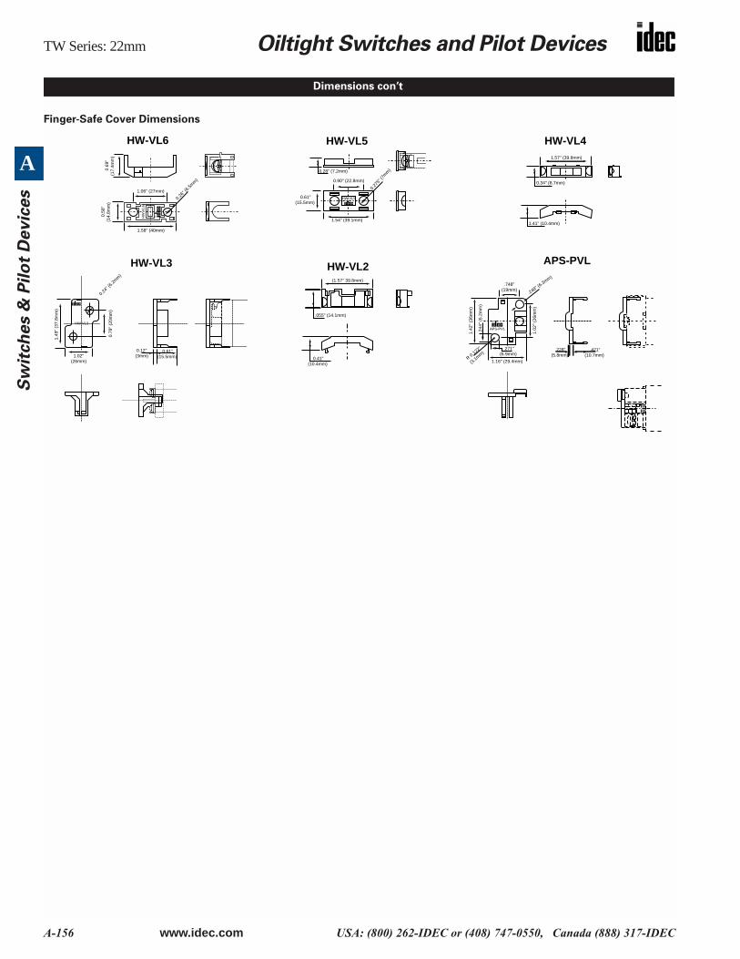
TW Series: 22mm Oiltight Switches and Pilot Devices
A-156 www.idec.com USA: (800) 262-IDEC or (408) 747-0550, Canada (888) 317-IDEC
A
Sw
itch
es &
Pil
ot
Devic
es
Finger-Safe Cover Dimensions
Dimensions con’t
APS-PVL
.748" (19mm)
.248" (6.3mm)
1.02
" (2
6mm
)
1.42
" (3
6mm
)
R 0.122"
(3.1mm)
1.16" (29.4mm)
.271" (6.9mm)
.244
" (6
.2m
m)
.228" (5.8mm)
.421" (10.7mm)
APS-PVL
HW
VL6
0
.69"
(1
7.4m
m)
0
.58"
(14
.8m
m)
1.06" (27mm)
1.58" (40mm)
0.26"
(6.5m
m)
HW-VL6
HW VL5
0.28" (7.2mm)
0.90" (22.8mm)
0.27
5" (7
mm
)
0.61" (15.5mm)
1.54" (39.1mm)
HW-VL5
HW-VL3
0.79
" (2
0mm
)
0.24"
(6.2m
m)
1.02" (26mm)
1.49
" (3
7.8m
m)
0.12"(3mm)
0.61" (15.5mm)
HW-VL3(1.57" 39.8mm)
.055" (14.1mm)
0.41"(10.4mm)
HW-VL2
HW-VL41.57" (39.8mm)
0.34" (8.7mm)
1.41" (10.4mm)
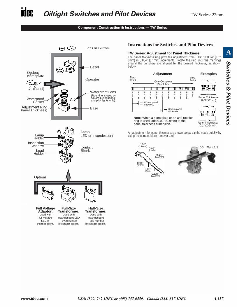
Oiltight Switches and Pilot Devices TW Series: 22mm
www.idec.com USA: (800) 262-IDEC or (408) 747-0550, Canada (888) 317-IDEC A-157
A
Sw
itch
es &
Pilo
t Devic
es
Instructions for Switches and Pilot Devices
TW Series: Adjustment for Panel ThicknessThe panel thickness ring provides adjustment from 0.04" to 0.24" (1 to6mm) in 0.004" (0.1mm) increments. Rotate the ring until the markingsaround the periphery are aligned for the desired thickness, as shownbelow.
An adjustment for panel thicknesses shown below can be made quickly byusing the contact block remover tool.
ZeroPoint
ZeroPointOne Complete
Revolution
0mm
0.1m
m
0.2m
m
0.3m
m
0.4m
m
0.5m
m
0.6m
m
0.7m
m
0.8m
m
0.9m
m
0mm
0.1mm panelthickness
0.5mm panelthickness
Note: When a nameplate or an anti-rotationring is used, add 0.03" (0.8mm) to thepanel thickness dimension.
Adjustment Examples
Panel Thickness:0.1" (2.6mm)
Panel Thickness:0.08" (2mm)
Tool TW-KC1(1.6mm)0.06"
(2.3mm)0.09"
(3.5mm)0.14"
(1mm)0.04"
(2mm)0.08"
(3.2mm)0.125"
Component Construction & Instructions — TW Series
square pushbuttons
Option:Nameplate
Operator
ContactBlock
Lens or Button
Bezel
Base
Lamp
Waterproof Lens(Round lens used on
WaterproofGasket
Adjustment RingPanel Thickness)
LED or Incandescent
InspectionWindow
LampHolder
LeadHolder
and pilot lights only).
Options
(Panel)
Full VoltageAdaptor:
Full-SizeTransformer:
Used withfull voltage
LED or
Used withincandescent/LED
– even numberof contact blocks.
Half-SizeTransformer:
Used withincandescent– odd number
of contact blocks.incandescent.
TW Series: 22mm Oiltight Switches and Pilot Devices
A-158 www.idec.com USA: (800) 262-IDEC or (408) 747-0550, Canada (888) 317-IDEC
A
Sw
itch
es &
Pil
ot
Devic
es
Pilot Lights and Pushbuttons
IMPORTANT: Install the body of the TW control unit with the panel thickness scale facing up.
Octagonal and Round Bezels
Octagonal and round bezels screw into the operator. Use the locking ring wrench (optional) for secure tightening and easy removal. Round flush and extended but-tons snap onto the operator base. Mushroom buttons screw onto the operator base.
Every round lens can be used with or without legend markings. Engraving can be done on a white translucent plate which is placed in the lens, or clear mylar canbe printed and placed in the lens.
Square Bezels
Square bezels are installed in a 3-step procedure. First install the base plate from the front. Then install the lock nut using the nut locking wrench (optional).Finally, install the square bezel, which snap-fits onto the base plate. Square buttons also snap onto the operator base.
Every square lens can be used with or without legend markings. Engraving can be done on a white translucent plate which is placed in the lens, or clear mylar canbe printed and placed in the lens. Square units include a round waterproof lens which screws into the operator. The square outer lens snaps on.
To remove square lens from operator, place a screwdriver under the indentation on the side of the lens. To remove the marking plate, place a screwdriver underthe indentation and lift out the plate. The lens retainer can be removed by pressing a 3/16" screwdriver into one of the recesses.
Marking Plate Engraving Area
Shape Engraving Area Used With Part Number
RoundØ 0.55" (14mm) Illuminated pushbuttons ALW2B
Ø 0.55" (14mm) Pilot lights APW2B
Mushroom Ø 0.55" (14mm) Illuminated mushroom ALW3B
Square 0.83" (21mm) Square pilot lights APQW1B
Square 0.83" (21mm) Square illuminatedpushbuttons ALQW2B
Instructions con’t
RoundMarkingUnit Press in
round flushand extendedlens. Screw inmushroom lens.
Insertmarking
plateunder lens.
SquareMarkingUnits
Pilot Light
Insertmarking
plateunder lens.
Insertmarking
plateunder lens.
IlluminatedPushbutton
Oiltight Switches and Pilot Devices TW Series: 22mm
www.idec.com USA: (800) 262-IDEC or (408) 747-0550, Canada (888) 317-IDEC A-159
A
Sw
itch
es &
Pilo
t Devic
es
Selector Switches
The operator shaft of each unit has a recess to identify in which direction to install the handle. Align the handle with the recess. Press color insert (TW-HC1) into the handle and then press handle into the operator, as shown below.
.
Standard Operating Positions
Positions: Non-illuminated 3-Position Operators
Installation
Installation of LED Illuminated Units
AC adaptor units are recommended for use in areas subjected to inductive noise. When using full voltage types, install a protection diode as shown below. Usediode with AC power supply to protect against reverse polarity. Use with DC power supply to protect against surges and noise.
.
2-Position, 90° 3-Position, 45° 4-Position, 45° 5-Position, 30°
Instructions con’t
RecessPress incolor insert
Press inhandle
IlluminatedSelector Switch
Non-IlluminatedSelector Switch
Remove color insert before pull ing out the handle.
1 2 1 20
1 32
41
3
542
1 20 1
2
01
2
0
TW Illuminated Pushbuttons,TW Selector Switches(AC Adaptor or Full Voltage)
Make sure slotis facing up
TW Pilot Lights
Terminal X1 = Positive
Terminal X2 =Negative
Lamp holder is installedas shown, due to polarity.Lead holder (used with twostacks of contact blocks)does not have polarity.
TerminalX1
TerminalX2
Diode
LED
Make sure that LED illuminated units are installed withcorrect polarity, as indicated at the terminals.
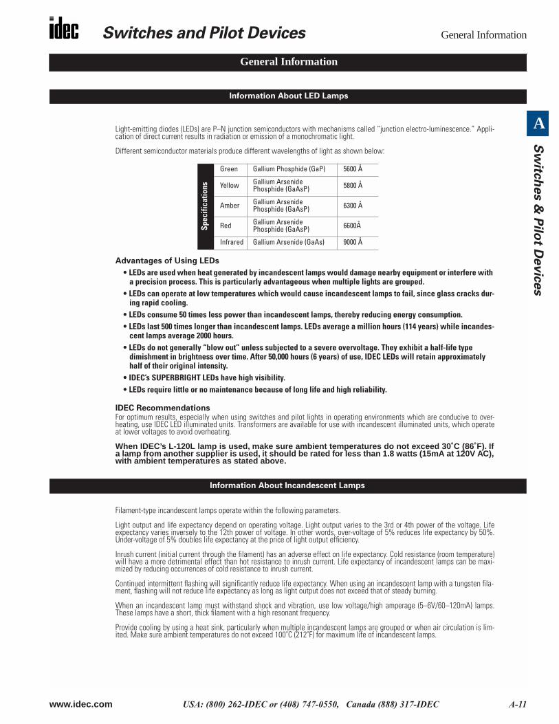
Switches and Pilot Devices General Information
www.idec.com USA: (800) 262-IDEC or (408) 747-0550, Canada (888) 317-IDEC A-11
A
Sw
itch
es &
Pilo
t Devic
es
Light-emitting diodes (LEDs) are P–N junction semiconductors with mechanisms called “junction electro-luminescence.” Appli-cation of direct current results in radiation or emission of a monochromatic light.
Different semiconductor materials produce different wavelengths of light as shown below:
Advantages of Using LEDs
• LEDs are used when heat generated by incandescent lamps would damage nearby equipment or interfere with a precision process. This is particularly advantageous when multiple lights are grouped.
• LEDs can operate at low temperatures which would cause incandescent lamps to fail, since glass cracks dur-ing rapid cooling.
• LEDs consume 50 times less power than incandescent lamps, thereby reducing energy consumption.• LEDs last 500 times longer than incandescent lamps. LEDs average a million hours (114 years) while incandes-
cent lamps average 2000 hours.• LEDs do not generally “blow out” unless subjected to a severe overvoltage. They exhibit a half-life type
dimishment in brightness over time. After 50,000 hours (6 years) of use, IDEC LEDs will retain approximately half of their original intensity.
• IDEC’s SUPERBRIGHT LEDs have high visibility.• LEDs require little or no maintenance because of long life and high reliability.
IDEC RecommendationsFor optimum results, especially when using switches and pilot lights in operating environments which are conducive to over-heating, use IDEC LED illuminated units. Transformers are available for use with incandescent illuminated units, which operateat lower voltages to avoid overheating.
When IDEC’s L-120L lamp is used, make sure ambient temperatures do not exceed 30˚C (86˚F). Ifa lamp from another supplier is used, it should be rated for less than 1.8 watts (15mA at 120V AC),with ambient temperatures as stated above.
Filament-type incandescent lamps operate within the following parameters.
Light output and life expectancy depend on operating voltage. Light output varies to the 3rd or 4th power of the voltage. Lifeexpectancy varies inversely to the 12th power of voltage. In other words, over-voltage of 5% reduces life expectancy by 50%.Under-voltage of 5% doubles life expectancy at the price of light output efficiency.
Inrush current (initial current through the filament) has an adverse effect on life expectancy. Cold resistance (room temperature)will have a more detrimental effect than hot resistance to inrush current. Life expectancy of incandescent lamps can be maxi-mized by reducing occurrences of cold resistance to inrush current.
Continued intermittent flashing will significantly reduce life expectancy. When using an incandescent lamp with a tungsten fila-ment, flashing will not reduce life expectancy as long as light output does not exceed that of steady burning.
When an incandescent lamp must withstand shock and vibration, use low voltage/high amperage (5–6V/60–120mA) lamps.These lamps have a short, thick filament with a high resonant frequency.
Provide cooling by using a heat sink, particularly when multiple incandescent lamps are grouped or when air circulation is lim-ited. Make sure ambient temperatures do not exceed 100˚C (212˚F) for maximum life of incandescent lamps.
Spec
ifica
tions
Green Gallium Phosphide (GaP) 5600 Å
Yellow Gallium ArsenidePhosphide (GaAsP) 5800 Å
Amber Gallium Arsenide Phosphide (GaAsP) 6300 Å
Red Gallium Arsenide Phosphide (GaAsP) 6600Å
Infrared Gallium Arsenide (GaAs) 9000 Å
General Information
Information About LED Lamps
Information About Incandescent Lamps
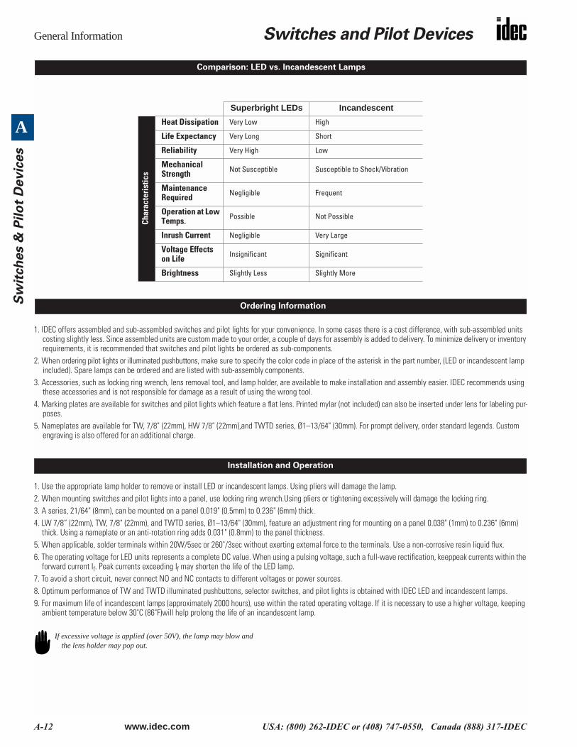
General Information Switches and Pilot Devices
A-12 www.idec.com USA: (800) 262-IDEC or (408) 747-0550, Canada (888) 317-IDEC
A
Sw
itch
es &
Pil
ot
Devic
es
1. IDEC offers assembled and sub-assembled switches and pilot lights for your convenience. In some cases there is a cost difference, with sub-assembled units costing slightly less. Since assembled units are custom made to your order, a couple of days for assembly is added to delivery. To minimize delivery or inventory requirements, it is recommended that switches and pilot lights be ordered as sub-components.
2. When ordering pilot lights or illuminated pushbuttons, make sure to specify the color code in place of the asterisk in the part number, (LED or incandescent lamp included). Spare lamps can be ordered and are listed with sub-assembly components.
3. Accessories, such as locking ring wrench, lens removal tool, and lamp holder, are available to make installation and assembly easier. IDEC recommends using these accessories and is not responsible for damage as a result of using the wrong tool.
4. Marking plates are available for switches and pilot lights which feature a flat lens. Printed mylar (not included) can also be inserted under lens for labeling pur-poses.
5. Nameplates are available for TW, 7/8" (22mm), HW 7/8" (22mm),and TWTD series, Ø1–13/64" (30mm). For prompt delivery, order standard legends. Custom engraving is also offered for an additional charge.
1. Use the appropriate lamp holder to remove or install LED or incandescent lamps. Using pliers will damage the lamp.2. When mounting switches and pilot lights into a panel, use locking ring wrench.Using pliers or tightening excessively will damage the locking ring.3. A series, 21/64" (8mm), can be mounted on a panel 0.019" (0.5mm) to 0.236" (6mm) thick.4. LW 7/8” (22mm), TW, 7/8" (22mm), and TWTD series, Ø1–13/64" (30mm), feature an adjustment ring for mounting on a panel 0.038" (1mm) to 0.236" (6mm)
thick. Using a nameplate or an anti-rotation ring adds 0.031" (0.8mm) to the panel thickness.5. When applicable, solder terminals within 20W/5sec or 260˚/3sec without exerting external force to the terminals. Use a non-corrosive resin liquid flux.6. The operating voltage for LED units represents a complete DC value. When using a pulsing voltage, such a full-wave rectification, keeppeak currents within the
forward current If. Peak currents exceeding If may shorten the life of the LED lamp.7. To avoid a short circuit, never connect NO and NC contacts to different voltages or power sources.8. Optimum performance of TW and TWTD illuminated pushbuttons, selector switches, and pilot lights is obtained with IDEC LED and incandescent lamps.9. For maximum life of incandescent lamps (approximately 2000 hours), use within the rated operating voltage. If it is necessary to use a higher voltage, keeping
ambient temperature below 30˚C (86˚F)will help prolong the life of an incandescent lamp.
Superbright LEDs Incandescent
Char
acte
rist
ics
Heat Dissipation Very Low High
Life Expectancy Very Long Short
Reliability Very High Low
Mechanical Strength Not Susceptible Susceptible to Shock/Vibration
Maintenance Required Negligible Frequent
Operation at Low Temps. Possible Not Possible
Inrush Current Negligible Very Large
Voltage Effects on Life Insignificant Significant
Brightness Slightly Less Slightly More
Comparison: LED vs. Incandescent Lamps
Ordering Information
Installation and Operation
If excessive voltage is applied (over 50V), the lamp may blow and the lens holder may pop out.