Embed Size (px)
Citation preview

Technical GuideTechnical GuideTechnical GuideTechnical GuideTechnical Guide
Feature Overview and Configuration GuideSwitching
Introduction
This guide gives an overview of Layers 1 and 2 Ethernet switching.
Layer 2 switches are used to connect multiple Local Area Network (LAN) segments
together to form an extended LAN. Stations connected to different LANs can be
configured to communicate with one another as if they were on the same LAN. They can
also divide one physical LAN into multiple Virtual LANs (VLANs). Stations connected to
each other on the same extended LAN can be grouped in separate VLANs, so that a
station in one VLAN can communicate at Layer 2 with other stations in the same VLAN,
but must go through higher layer routing protocols to communicate with stations in other
VLANs.
Layer 2 switches appear transparent to higher layer protocols, transferring frames
between the data link layers of the networks to which they are attached. A Layer 2 switch
accesses each physical link according to the rules for that particular network. Access may
not always be instant if a link's bandwidth is oversubscribed, so the switch must be
capable of storing and forwarding frames.
Storing and forwarding enables the switch to examine both the VLAN tag fields and
Ethernet MAC address fields in order to forward the frames to their appropriate
destination. In this way, the switch can act as an intelligent filtering device, redirecting or
blocking the movement of frames between networks.
Because switch ports can sometimes receive frames faster than it can forward them, the
switch has Quality of Service (QoS) queues in which frames await transmission according
to their priority. Such a situation could occur where data enters a number of input ports all
destined for the same output port.
x alliedtelesis.comC613-22037-00 REV B

Switching
The switch can be used to:
Increase both the physical extent and the maximum number of stations on a LAN. LANs
are limited in their physical extent by the signal distortion and propagation delay
characteristics of the media. The switch overcomes this limitation by receiving a frame
on one LAN and then retransmitting it to another. The physical characteristics of the
LAN media also place a practical limit on the number of stations that can be connected
to a single LAN segment. The switch overcomes this limitation by joining LAN
segments to form an extended LAN capable of supporting more stations than either of
the individual LAN segments.
Connect LANs that have a common data link layer protocol but different physical
media, for example, Ethernet 10BASET, 100BASET, and 10BASEF.
Increase the availability of LANs by allowing multiple redundant paths to be physically
configured and selected dynamically, using the Spanning Tree algorithm.
Reduce the load on a LAN or increase the effective bandwidth of a LAN, by filtering
traffic.
Prioritize the transmission of data with high Quality of Service requirements.
By using Virtual LANs (VLANs), a single physical LAN can be separated into multiple
Virtual LANs. VLANs can be used to:
Further improve LAN performance, as broadcast traffic is limited to LAN segments
serving members of the VLAN to which the sender belongs.
Provide security, as frames are forwarded to those stations belonging to the sender’s
VLAN, and not to stations in other VLANs on the same physical LAN.
Reduce the cost of moving or adding stations to function or security based LANs, as
this generally requires only a change in the VLAN configuration.
Products and software version that apply to this guide
This guide applies to all AlliedWare Plus™ products, running version 5.4.4 or later.
However, feature support and implementation varies between products. To see whether a
product supports a particular feature or command, see the following documents:
The product’s Datasheet
The product’s Command Reference
These documents are available from the above links on our website at alliedtelesis.com.
Most features described in this document are supported from AlliedWare Plus 5.4.4 or
later. These features are available in later releases:
Version 5.4.7-0.1 and later supports extended hardware switching on x310 Series
switches
Page 2 | Products and software version that apply to this guide

Switching
ContentIntroduction.........................................................................................................................1
Products and software version that apply to this guide...............................................2
Switch Ports........................................................................................................................4
Port numbering.............................................................................................................4
Adding a description to an interface ............................................................................4
Port ranges ...................................................................................................................5
Activating and deactivating switch ports .....................................................................5
Autonegotiation ............................................................................................................5
Duplex mode ................................................................................................................6
Speed options ..............................................................................................................6
MDI/MDIX connection modes ......................................................................................6
The Layer 2 Switching Process...........................................................................................7
The ingress rules ..........................................................................................................8
Determining the VLAN to associate with untagged (or priority tagged) frames ...........8
Reasons why a Frame Might not be Accepted on a Port .................................................11
Access and trunk modes............................................................................................11
The learning process ..................................................................................................11
The forwarding process..............................................................................................12
The egress rules .........................................................................................................13
Layer 2 Filtering.................................................................................................................14
Ingress filtering ...........................................................................................................14
Discard entries in the MAC table................................................................................14
Storm Control....................................................................................................................15
Loop Protection ................................................................................................................16
Loop detection ...........................................................................................................16
Thrash limiting ............................................................................................................18
Support for Jumbo Frames...............................................................................................19
Port Security .....................................................................................................................20
MAC address learn limits ...........................................................................................20
IEEE 802.1X ................................................................................................................20
Static MAC address....................................................................................................20
Extended hardware switching on x310 Series switches...................................................21
Products and software version that apply to this guide | Page 3

Switching
Switch Ports
The switch ports in the x-series switches support a number of features:
Enabling and disabling of ports
Auto negotiation of port speed and duplex mode, where supported by the port type
Manual setting of port speed and duplex mode, where supported by the port type
Link up and link down triggers
Packet storm protection
Port mirroring
Port numbering
A unique port number identifies each switch port on a device.
Ports are numbered using a 3 digit format x.y.z where:
x is the device number (1 for a standalone device, or from 1 to 8 for a device in a
VCStack™)
y is a module number (for devices that have plugin line cards or other modules) or 0
for ports on the base device chassis.
z is the port number within the module or on the base device chassis.
In an unstacked (standalone) configuration all device numbers are 1. For example,
port1.0.37 represents device 1, port 37 on the device chassis (i.e. not in a plug-in card),
and port1.2.6 represents device 1, card 2, port 6.
In a VCStack, port2.0.8 represents device 2, port 8 on the switch chassis.
Adding a description to an interface
You can add a description to an interface to help identify its purpose or position. For
example, to add the description “connected to Nerv” to port1.0.3, use the commands:
awplus(config)#interface port1.0.3awplus(config-if)#description connected to Nerv
Page 4 | Port numbering

Switching
Port ranges
Continuous To configure properties of a continuous range of ports at the same time, enter the range in
the format:
portx.y.z-portx.y.z
For example, to configure the same interface setting on port1.0.1 to port1.0.2, enter the
Global Configuration mode command:
awplus(config)#interface port1.0.1-port1.0.2
Non-continuous
To configure a non-continuous set of ports at the same time, enter a comma-separated
list:
portx.y.z,portx.y.z
For example, to configure the same interface setting on port1.0.1 and port1.0.5, enter the
Global Configuration mode command:
awplus(config)#interface port1.0.1,port1.0.5
You can combine a hyphen-separated range and a comma-separated list. To configure
the same setting on port1.0.1 to port1.0.3 and port1.0.5, enter the Global Configuration
mode command:
awplus(config)#interface port1.0.1-port1.0.3,port1.0.5
Activating and deactivating switch ports
An active switch port is one that is available for packet reception and transmission. By
default ports and VLANs are activated.
To deactivate (shutdown) a port or VLAN use the shutdown command. Use the no variant
of this command to reactivate it.
Autonegotiation
Autonegotiation lets the port adjust its speed and duplex mode to accommodate the
device connected to it. When the port connects to another autonegotiating device, they
negotiate the highest possible speed and duplex mode for both of them.
By default, all ports autonegotiate. Setting the port to a fixed speed and duplex mode may
be necessary when connecting to a device that cannot autonegotiate.
We recommend having autonegotiation enabled for link speeds of 1000 Mbps and above. For example, to apply a fixed speed of 1000 Mbps use the command, speed auto 1000.
Port ranges | Page 5

Switching
Duplex mode
Ports can operate in full duplex or half duplex mode depending on the type of port it is.
When in full duplex mode, a port transmits and receives data simultaneously. When in half
duplex mode, the port transmits or receives but not both at the same time.
You can set a port to use either of these options, or allow it to autonegotiate the duplex
mode with the device at the other end of the link. To configure the duplex mode, use these
commands:
awplus#configure terminalawplus(config)#interface port1.0.1awplus(config-if)#duplex {auto|full|half}
Make sure that the configuration of the switch matches the configuration of the device at
the far end of the link. In particular, avoid having one end autonegotiate duplex mode
while the other end is fixed. For example, if you set one end of a link to autonegotiate and
fix the other end at full duplex, the autonegotiating end cannot determine that the fixed
end is full duplex capable. Therefore, the autonegotiating end selects half-duplex
operation. This results in a duplex mismatch and packet loss. To avoid this, either fix the
mode at both ends, or use autonegotiation at both ends.
Speed options
Before configuring a port’s speed, check the hardware limit for the particular port type.
For the latest list of approved SFP transceivers either contact your authorized distributor
or reseller, or visit alliedtelesis.com.
You can set a port to use one of multiple speed options, or allow it to autonegotiate the
speed with the device at the other end of the link.
We recommend having autonegotiation enabled for link speeds of 1000 Mbps and above.
Configuring the port speed
To set port1.0.1 to auto-negotiate its speed at 1000 Mbps only, which will fix this port
speed to 1000 Mbps, enter the following commands:
awplus#configure terminalawplus(config)#interface port1.0.1awplus(config-if)#speed auto 1000
MDI/MDIX connection modes
By default, copper 10Base-T, 100Base-T, and 1000Base-T ports on the switch
automatically set the Media Dependant Interface mode to MDI or MDIX for successful
physical connections. We recommend using this default setting. However, you can
configure them to have either fixed MDI mode or fixed MDIX mode by using the polarity
command. MDI/MDIX mode polarity does not apply to fiber ports.
Connections to 10BASE-T, 100BASE-T, and 1000BASE-T networks may either be straight
though (MDI) or crossover (MDIX). The crossover connection can be achieved by using
Page 6 | Duplex mode

Switching
either a crossover cable or by integrating the crossover function within the device. In the
latter situation, the connector is referred to as an MDIX connection. Refer to your switch’s
Installation Guide for more detailed information on physical connections cabling.
The IEEE 802.3 standard defines a series of Media Dependant Interface types and their
physical connections. For twisted pair networking, the standard defines connectors that
conform to the IEC 60603-7 standard. The following figure shows a connector of this type:
The Layer 2 Switching ProcessThe Layer 2 switching process comprises these related but separate processes:
"The ingress rules" on page 8
"The learning process" on page 11
"The forwarding process" on page 12
"The egress rules" on page 13
Here is a brief description for each of these processes:
Ingress rules admit or discard frames based on their VLAN tagging.
The Learning process learns the MAC addresses and VLAN membership of frames
admitted on each port.
The Forwarding process determines which ports the frames are forwarded to, and the
Quality of Service priority with which they are transmitted.
Finally, Egress rules determine for each frame whether VLAN tags are included in the
Ethernet frames that are transmitted.
These processes assume that each station on the extended LAN has a unique Data Link
Layer address, and that all data link layer frames have a header which includes the source
(sender’s) MAC address and destination (recipient’s) MAC address.
18
18
RJPIN
MDI/MDIX connection modes | Page 7
Switching
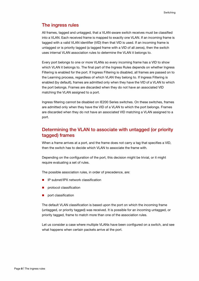
The ingress rules
All frames, tagged and untagged, that a VLAN-aware switch receives must be classified
into a VLAN. Each received frame is mapped to exactly one VLAN. If an incoming frame is
tagged with a valid VLAN identifier (VID) then that VID is used. If an incoming frame is
untagged or is priority tagged (a tagged frame with a VID of all zeros), then the switch
uses internal VLAN association rules to determine the VLAN it belongs to.
Every port belongs to one or more VLANs so every incoming frame has a VID to show
which VLAN it belongs to. The final part of the Ingress Rules depends on whether Ingress
Filtering is enabled for the port. If Ingress Filtering is disabled, all frames are passed on to
the Learning process, regardless of which VLAN they belong to. If Ingress Filtering is
enabled (by default), frames are admitted only when they have the VID of a VLAN to which
the port belongs. Frames are discarded when they do not have an associated VID
matching the VLAN assigned to a port.
Ingress filtering cannot be disabled on IE200 Series switches. On these switches, frames
are admitted only when they have the VID of a VLAN to which the port belongs. Frames
are discarded when they do not have an associated VID matching a VLAN assigned to a
port.
Determining the VLAN to associate with untagged (or priority tagged) frames
When a frame arrives at a port, and the frame does not carry a tag that specifies a VID,
then the switch has to decide which VLAN to associate the frame with.
Depending on the configuration of the port, this decision might be trivial, or it might
require evaluating a set of rules.
The possible association rules, in order of precedence, are:
IP subnet/IPX network classification
protocol classification
port classification
The default VLAN classification is based upon the port on which the incoming frame
(untagged, or priority tagged) was received. It is possible for an incoming untagged, or
priority tagged, frame to match more than one of the association rules.
Let us consider a case where multiple VLANs have been configured on a switch, and see
what happens when certain packets arrive at the port.
Page 8 | The ingress rules
Switching
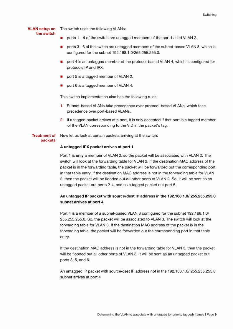
VLAN setup on the switch
The switch uses the following VLANs:
ports 1 - 4 of the switch are untagged members of the port-based VLAN 2.
ports 3 - 6 of the switch are untagged members of the subnet-based VLAN 3, which is
configured for the subnet 192.168.1.0/255.255.255.0.
port 4 is an untagged member of the protocol-based VLAN 4, which is configured for
protocols IP and IPX.
port 5 is a tagged member of VLAN 2.
port 6 is a tagged member of VLAN 4.
This switch implementation also has the following rules:
1. Subnet-based VLANs take precedence over protocol-based VLANs, which take precedence over port-based VLANs.
2. If a tagged packet arrives at a port, it is only accepted if that port is a tagged member of the VLAN corresponding to the VID in the packet's tag.
Treatment of packets
Now let us look at certain packets arriving at the switch:
A untagged IPX packet arrives at port 1
Port 1 is only a member of VLAN 2, so the packet will be associated with VLAN 2. The
switch will look at the forwarding table for VLAN 2. If the destination MAC address of the
packet is in the forwarding table, the packet will be forwarded out the corresponding port
in that table entry. If the destination MAC address is not in the forwarding table for VLAN
2, then the packet will be flooded out all other ports of VLAN 2. So, it will be sent as an
untagged packet out ports 2-4, and as a tagged packet out port 5.
An untagged IP packet with source/dest IP address in the 192.168.1.0/ 255.255.255.0
subnet arrives at port 4
Port 4 is a member of a subnet-based VLAN 3 configured for the subnet 192.168.1.0/
255.255.255.0. So, the packet will be associated to VLAN 3. The switch will look at the
forwarding table for VLAN 3. If the destination MAC address of the packet is in the
forwarding table, the packet will be forwarded out the corresponding port in that table
entry.
If the destination MAC address is not in the forwarding table for VLAN 3, then the packet
will be flooded out all other ports of VLAN 3. It will be sent as an untagged packet out
ports 3, 5, and 6.
An untagged IP packet with source/dest IP address not in the 192.168.1.0/ 255.255.255.0
subnet arrives at port 4
Determining the VLAN to associate with untagged (or priority tagged) frames | Page 9

Switching
Port 4 is a member of a subnet-based VLAN 3 configured for the subnet 192.168.1.0/
255.255.255.0, but the packet's addresses are not in that subnet. So, the packet will not
be associated with VLAN 3.
The next VLAN type in the precedence order is the protocol-based VLAN. Port 4 is a
member of the protocol-based VLAN 4, configured for IP and IPX. As this is an IP packet,
it will be associated with VLAN 4.
The switch only has one other port in VLAN 4. The packet will be sent as a tagged packet
out port 6.
An untagged AppleTalk packet arrives at port 4
The AppleTalk packet cannot be associated with the subnet-based or the protocol-based
VLANs on port 4, so it must drop through to the port-based VLAN on port 4. So the packet
is associated with VLAN 2. The switch will look at the forwarding table for VLAN 2. If the
destination MAC address of the packet is in the forwarding table, the packet will be
forwarded out the corresponding port in that table entry. If the destination MAC address is
not in the forwarding table for VLAN 2, then the packet will be flooded out all other ports
of VLAN 2. So, it will be sent as an untagged packet out ports 1-3, and as a tagged packet
out port 5.
A tagged IPX packet arrives at port 4
Port 4 is an untagged member of the protocol-based VLAN 4, configured for IP and IPX.
But, the packet is tagged, so it will be dropped.
A tagged packet with VID=10 arrives at port 5
Port 5 is a tagged member of VLAN 2. But the VID in the packet's tag does not match the
VID of the VLAN (2), so the packet is dropped.
A tagged packet with VID=2 arrives at port 5
Port 5 is a tagged member of VLAN 2. The VID in the packet's tag matches the VID of the
VLAN, so the packet is associated with VLAN 2.
The switch will look at the forwarding table for VLAN 2. If the destination MAC address of
the packet is in the forwarding table, the packet will be forwarded out the corresponding
port in that table entry. If the destination MAC address is not in the forwarding table for
VLAN2, then the packet will be flooded out all other ports of VLAN 2. So, it will be sent as
an untagged packet out ports 1-4.
Page 10 | Determining the VLAN to associate with untagged (or priority tagged) frames

Switching
Reasons why a Frame Might not be Accepted on a Port The port is in a spanning tree blocking or discarding state
The port is blocked by storm control
An ACL configured on the port drops the packet.
Access and trunk modes
Each port on the switch can be configured to be one of two modes:
only untagged frames - access mode
VLAN-tagged frames - trunk mode
Access mode
This mode can be used to connect to VLAN unaware devices. Frames to and from access
mode ports carry no VLAN tagging information.
Trunk mode
This mode is used to connect VLAN capable devices. All devices that connect using trunk
mode ports must be VLAN aware.
A port in trunk mode is associated with one of more VLANs for which it will transmit and
accept packets tagged with the VIDs of those VLANs.
You can specify a “native” VLAN on a trunk port. When the port receives untagged
packets, it will tag the packets with the VID of the native VLAN. Note that packets from the
native VLAN egress the port untagged.
To specify the native VLAN, use the switchport trunk native vlan command.
The learning process
The learning process uses an adaptive learning algorithm, sometimes called backward
learning, to discover the location of each station on the extended LAN.
All frames admitted by the ingress rules on any port are passed on to the Layer 2
forwarding process when they are for destinations in the same VLAN. Frames destined for
other VLANs are passed to a Layer 3 protocol, such as IP. For every frame admitted, the
frame’s source MAC address and VID are compared with entries in the forwarding
database for the VLAN (also known as a MAC Address table) maintained by the switch.
When the frame’s source address is not in the forwarding database for the VLAN, the
address is added and associated with the port on which the frame arrived, and an ageing
timer for that entry is started. When the frame’s source address is already in the
forwarding database, the ageing timer for that entry is restarted.
Access and trunk modes | Page 11
Switching
By default, switch learning is enabled. It can be disabled with the no mac address-table
acquire command, and re-enabled using the mac address-table acquire command.
If the ageing timer for an entry in the forwarding database expires before another frame
with the same source address is received, the entry is removed from the forwarding
database. This prevents the forwarding database from being filled with information about
stations that are inactive or have been disconnected from the network. It also ensures that
entries for active stations are kept alive in the forwarding database.
By default, the ageing timer is enabled with a default ageing-time. The default for the MAC
address-table ageing-time is 300 seconds (5 minutes) and can be modified by using the
command mac address-table ageing-time. The no mac address-table ageing-time
command will reset the ageing-time back to the default (5 minutes).
If switch learning is disabled and the ageing timer has aged out all dynamically learned
filter entries, only statically entered MAC source addresses are present in the database.
When the switch finds no matching entries in the forwarding database during the
forwarding process, all switch ports in the VLAN are flooded with the packet, except the
port that received it.
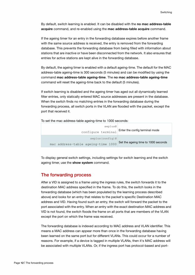
To set the mac address-table ageing-time to 1000 seconds:
To display general switch settings, including settings for switch learning and the switch
ageing timer, use the show system command.
The forwarding process
After a VID is assigned to a frame using the ingress rules, the switch forwards it to the
destination MAC address specified in the frame. To do this, the switch looks in the
forwarding database (which has been populated by the learning process described
above) and looks for an entry that relates to the packet's specific Destination MAC
address and VID. Having found such an entry, the switch will forward the packet to the
port associated with the entry. When an entry with the exact destination MAC address and
VID is not found, the switch floods the frame on all ports that are members of the VLAN
except the port on which the frame was received.
The forwarding database is indexed according to MAC address and VLAN identifier. This
means a MAC address can appear more than once in the forwarding database having
been learned on the same port but for different VLANs. This could occur for a number of
reasons. For example, if a device is tagged in multiple VLANs, then it's MAC address will
be associated with multiple VLANs. Or, if the ingress port has protocol-based and port-
awplus#
configure terminalEnter the config terminal mode
awplus(config)#
mac address-table ageing-time 1000Set the ageing time to 1000 seconds
Page 12 | The forwarding process

Switching
based classification rules, some packets from a given MAC might match the protocol
classification rule, and some the port-based classification rules.
A frame might not actually be transmitted out the egress port, for a number of reasons:
the destination port is in a spanning-tree blocking, discarding, listening, or learning
state
there is a static filter entry for the destination address set to discard (see "Layer 2
Filtering" on page 14). Otherwise, the frame is forwarded on the indicated port.
storm control is currently blocking the port
The egress rules
After the forwarding process has determined from which ports and transmission queues
to forward a frame to, the egress rules for each port determine whether the outgoing
frame is VLAN-tagged with its numerical VLAN identifier (VID).
A port must belong to a VLAN at all times unless the port has been set as the mirror port
for the switch.
A port can transmit VLAN-tagged frames for any VLAN to which the port belongs. A port
can transmit untagged frames for any VLAN for which the port is configured, e.g. IP
subnet-based or protocol-based, unless prevented by the port-based VLAN egress rules.
A port that belongs to a port-based VLAN can transmit untagged packets for only one
VLAN. For more information about VLANs and VLAN tagging, see the VLAN Feature
Overview and Configuration Guide.
For more information on port tagging, see the following commands in your product’s
Command Reference:
switchport mode access
switchport mode trunk
The Command Reference is available on our website at alliedtelesis.com.
The egress rules | Page 13

Switching
Layer 2 Filtering
Ingress filtering
The ingress-filter parameter of the switchport mode trunk command and the
switchport mode access command enables or disables ingress filtering of frames
entering the specified port (or port range).
Each port on the switch belongs to one or more VLANs. If ingress filtering is enabled, any
frame received on the specified port is only admitted if its VID matches one for which the
port is tagged. Any frame received on the port is discarded if its VID does not match one
for which the port is tagged.
Untagged frames are admitted and are assigned the VLAN Identifier (VID) of the port’s
native VLAN. If a port is in trunk mode, and the native VLAN on the port has been explicitly
set to none, and ingress filtering is enabled on the port, then untagged frames entering the
port will be discarded. Ingress filtering can be turned off by setting the disable parameter
of the above two commands. The default setting of the enable / disable parameter option
is enable.
Ingress filtering cannot be disabled on IE200 Series switches. On these switches, any
frame received on the specified port is only admitted if its VID matches one for which the
port is tagged. Any frame received on the port is discarded if its VID does not match one
for which the port is tagged.
Note: Enabling the vlan-disable parameter of the thrash-limiting command will also enable ingress filtering, and will override the setting of the switchport mode access, and trunk commands
Discard entries in the MAC table
To explicitly prevent the Layer 2 forwarding of frames to certain MAC addresses on certain
VLANs, it is possible to create static entries in the MAC table that have an action of
Discard:
mac address-table static <mac-addr> discard interface <port> [vlan <vid>]
Page 14 | Ingress filtering

Switching
Storm ControlThe packet storm-control feature enables you to set limits on the reception rate of
broadcast, multicast frames and destination lookup failures. You can set separate limits
beyond which each of the different packet types are discarded.
Note: A destination lookup failure (DLF) is the event of receiving a unicast Ethernet frame with an unknown destination address.
For more information on applying storm-control, see the storm-control level command.
To apply storm-control by limiting broadcasts to 30% on port1.0.4:
To turn off storm protection on port1.0.4:
awplus(config-if)#
configure terminalEnter Global Configuration mode.
awplus(config-if)#
interface port1.0.4Enter the Interface Configuration mode for the selected port.
awplus(config-if)#
storm-control broadcast level 30 Configure the interface.
awplus(config-if)#
configure terminalEnter Global Configuration mode.
awplus(config-if)#
interface port1.0.4Enter the Interface Configuration mode for the selected port.
awplus(config-if)#
no storm-control broadcast levelConfigure the interface.
Discard entries in the MAC table | Page 15

Switching
Loop ProtectionLoop protection is a general term that embraces several different methods you can apply
to protect your network from effects such as broadcast storms that can result from data
loops or equipment malfunction.
Two methods of loop protection are available in AlliedWare Plus:
"Loop detection" on page 16
"Thrash limiting" on page 18
Loop detection
Introduction
This feature is used to detect loops with a network segment. If a loop is detected then a
selected protection mechanism is applied to limit the effect of the loop. The loop
protection actions can be applied either to the port at which the loop is detected or to the
VLAN within which the loop was detected.
Limiting actions
You can configure loop detection to apply one of the following mechanisms when a loop
condition is detected:
Block all traffic on the port (or aggregated link) that detected the loop, and take down
the link.
Block all traffic on the port (or aggregated link) that detected the loop, but keep the link
in the up state.
Block all traffic on a VLAN. Note that setting this parameter will also enable ingress
filtering. This is the default action.
Take no action, but log the details.
Take no action.
Page 16 | Loop detection
Switching
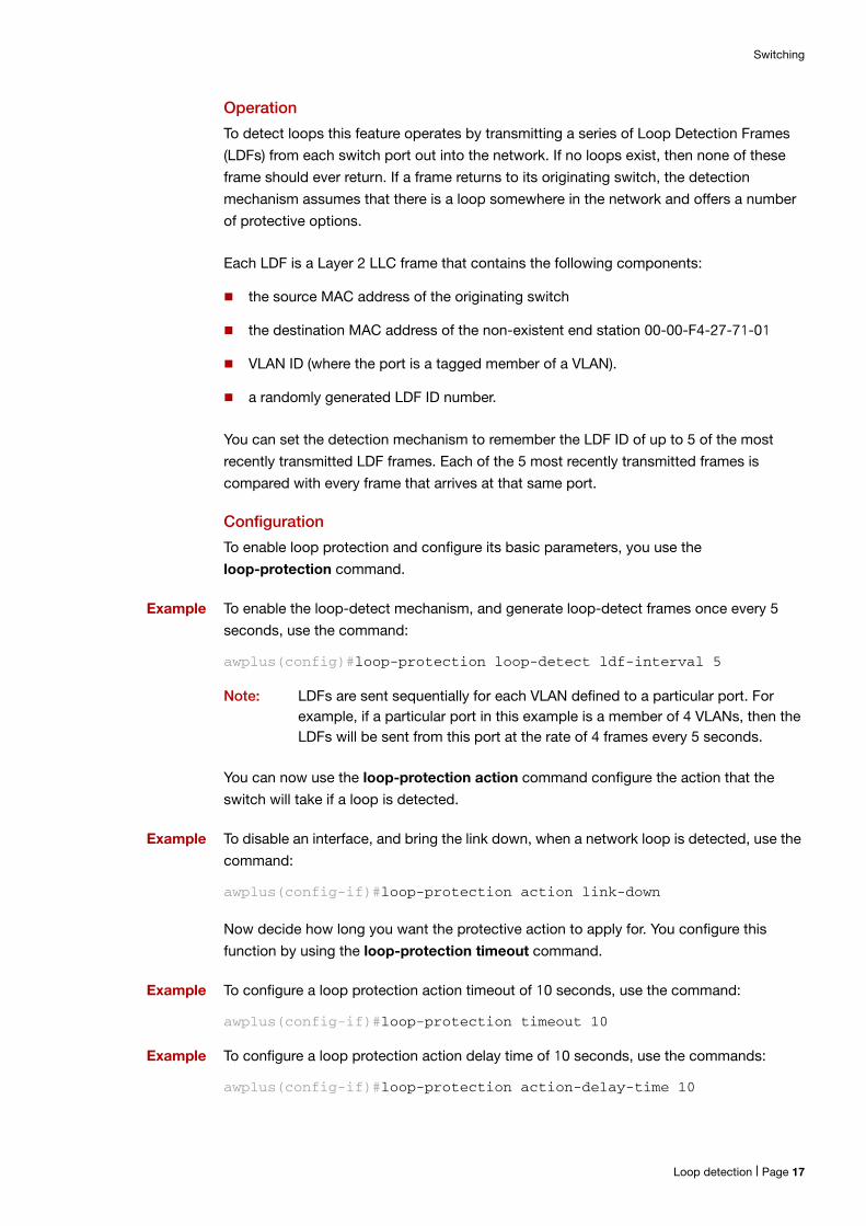
Operation
To detect loops this feature operates by transmitting a series of Loop Detection Frames
(LDFs) from each switch port out into the network. If no loops exist, then none of these
frame should ever return. If a frame returns to its originating switch, the detection
mechanism assumes that there is a loop somewhere in the network and offers a number
of protective options.
Each LDF is a Layer 2 LLC frame that contains the following components:
the source MAC address of the originating switch
the destination MAC address of the non-existent end station 00-00-F4-27-71-01
VLAN ID (where the port is a tagged member of a VLAN).
a randomly generated LDF ID number.
You can set the detection mechanism to remember the LDF ID of up to 5 of the most
recently transmitted LDF frames. Each of the 5 most recently transmitted frames is
compared with every frame that arrives at that same port.
Configuration
To enable loop protection and configure its basic parameters, you use the loop-protection command.
Example To enable the loop-detect mechanism, and generate loop-detect frames once every 5
seconds, use the command:
awplus(config)#loop-protection loop-detect ldf-interval 5
Note: LDFs are sent sequentially for each VLAN defined to a particular port. For example, if a particular port in this example is a member of 4 VLANs, then the LDFs will be sent from this port at the rate of 4 frames every 5 seconds.
You can now use the loop-protection action command configure the action that the
switch will take if a loop is detected.
Example To disable an interface, and bring the link down, when a network loop is detected, use the
command:
awplus(config-if)#loop-protection action link-down
Now decide how long you want the protective action to apply for. You configure this
function by using the loop-protection timeout command.
Example To configure a loop protection action timeout of 10 seconds, use the command:
awplus(config-if)#loop-protection timeout 10
Example To configure a loop protection action delay time of 10 seconds, use the commands:
awplus(config-if)#loop-protection action-delay-time 10
Loop detection | Page 17

Switching
Thrash limiting
MAC address thrashing occurs when MAC addresses move rapidly between one or more
ports or trunks, for example, due to a network loop.
Thrash limiting enables you to apply actions to a port when thrashing is detected. It is
supported on all port types and also on aggregated ports.
Limiting Actions
There are several different thrash actions that you can apply to a port when thrashing is
detected. These actions are:
learnDisable: MAC address learning is temporarily disabled on the port.
portDisable: The port is logically disabled. Traffic flow is prevented, but the link
remains up. The device at the other end does not notice that the port has changed
status, and the link LEDs at both ends stay on.
linkDown: The port is physically disabled and the link is down. This is equivalent to
entering the shutdown command.
vlanDisable: The port is disabled only for the VLAN on which thrashing has occurred.
It can still receive and transmit traffic for any other VLANs of which it is a member.
When a MAC address is thrashing between two ports, one of these ports (the first to cross
its thrashing threshold) is disabled. All other ports on the device will then have their
threshold counters reset.
To set a thrash action for a port, use the thrash-limiting command.
To view the thrash action that is set for a port, use the show interface switchport
command.
Re-enabling a port
When a port is disabled, either completely or for a specific VLAN, it remains disabled until
it is manually re-enabled in any of the following ways:
by using SNMP
by rebooting the switch or stack
by specifying a thrash timeout value along with the thrash action
via the CLI
Page 18 | Thrash limiting

Switching
Support for Jumbo Frames
Jumbo frames are frames with more than 1500 bytes of payload. You can enable jumbo
frame support on the switch to improve throughput and network utilization. Jumbo frame
support allows you to put more data in each packet that the switch has to process.
Once jumbo frame support is enabled, the maximum received packet size is:
9710 bytes for IE200 switches, and AR3050S and AR4050S AR-Series Firewalls. On
these platforms, we recommend that there are no more than two simultaneously
running ports with jumbo frames enabled
10240 bytes for SBx908, SBx8100 Series and x900 Series switches
12292 bytes for DC2552XS switches
16357 bytes for other AlliedWare Plus switches
The command to use to enable jumbo frame support varies between products, but is one
of:
mru <mru-size>
mru jumbo
platform jumboframe
To see which command your product supports, see the product’s Command Reference
on our website at alliedtelesis.com.
Note: Jumbo Frame forwarding is supported only for Layer 2 switching, not for Layer 3 switching.
Thrash limiting | Page 19

Switching
Port SecurityThe port security features provide control over the stations connected to each switch port
as follows.
MAC address learn limits
IEEE 802.1X
Static MAC address
MAC address learn limits
MAC address limiting is applied using the switchport port-security command. If enabled
on a port, the switch will learn MAC addresses up to a user-defined limit from 1 to 256,
then lock out all other MAC addresses. One of the following options can be specified for
the action taken when an unknown MAC address is detected on a locked port:
Discard the packet and take no further action.
Discard the packet and notify management with an SNMP trap.
Discard the packet, notify management with an SNMP trap, and disable the port.
IEEE 802.1X
IEEE 802.1X restricts unauthenticated devices from connecting to the switch. After
authentication is successful, traffic is allowed through the switch. For more information,
see the AAA and Port Authentication Feature Overview and Configuration Guide
Static MAC address
If a new MAC address is seen on a port with port security enabled and the MAC address
is statically configured for another port, a violation is triggered. The maximum learn limit
will be ignored and the specified intrusion action for the port will be carried out. On the
SBx908 and x900 Series switches, note that this behavior does not apply to switches
using Hardware Version 1 XEMs, as shown in the following table.
On SBx908 and x900 Series switches (but not for the SBx908 GEN2 switch), two
hardware types exist: Hardware Version 1 and Hardware Version 2. The following table
shows the hardware modules and the version to which each belongs:
Table 1: Hardware types and modules
HARDWARE VERSION 1 HARDWARE VERSION 2
Baseboard XEM-12Sv2
XEM-12T XEM-12Tv2
XEM-12S XEM-2XP
XEM-1XP XEM-2XS
XEM-2XT
XEM-24T
Page 20 | MAC address learn limits
Extended hardware switching on x310 Series switches
From version 5.4.7-0.1 onwards, x310 Series switches can hardware-switch traffic to
individual hosts in remote networks, if those remote networks are not covered by any
routes in the hardware route table. This means the switch can hardware-switch to
additional remote hosts when the hardware route table is full.
If the extended hardware switching is disabled (and in versions before 5.4.7-0.1), the
switch processes traffic for each such host via the CPU every time it has to send traffic to
the host. If the extended hardware switching is enabled, the switch only processes traffic
via the CPU the first time it has to send traffic to the host. Then it copies the host into the
switch’s hardware host table and hardware-switches future traffic to it.
To enable the extended hardware switching, use the following command:
awplus(config)#fib cache-remote-host
C613-22037-00 REV B
NETWORK SMARTER
alliedtelesis.com
North America Headquarters | 19800 North Creek Parkway | Suite 100 | Bothell | WA 98011 | USA | T: +1 800 424 4284 | F: +1 425 481 3895
Asia-Pacific Headquarters | 11 Tai Seng Link | Singapore | 534182 | T: +65 6383 3832 | F: +65 6383 3830
EMEA & CSA Operations | Incheonweg 7 | 1437 EK Rozenburg | The Netherlands | T: +31 20 7950020 | F: +31 20 7950021
© 2018 Allied Telesis, Inc. All rights reserved. Information in this document is subject to change without notice. All company names, logos, and product designs that are trademarks or registered trademarks are the property of their respective owners.