Embed Size (px)
Citation preview
SWPF System Description
Alpha Strike Process X-SD-J-00001, Rev. 2
Summary of Changes
SUMMARY OF CHANGES
Revision No. Date Description of Change
0 05/20/08 Issued for Enhanced Final Design
1 06/03/15 Revise per DCN-0641 and DCN-1472. This is a complete
rewrite. No deletions or Revision bars shown.
2 09/24/2019 Revise per DCN-2039, DCN-7015, and DCN-2101.

SWPF System Description
Alpha Strike Process X-SD-J-00001, Rev. 2
Table of Contents
TABLE OF CONTENTS
1.0 SCOPE ................................................................................................................................1
2.0 GENERAL OVERVIEW ..................................................................................................2
3.0 AST-A (TK-101) .................................................................................................................5
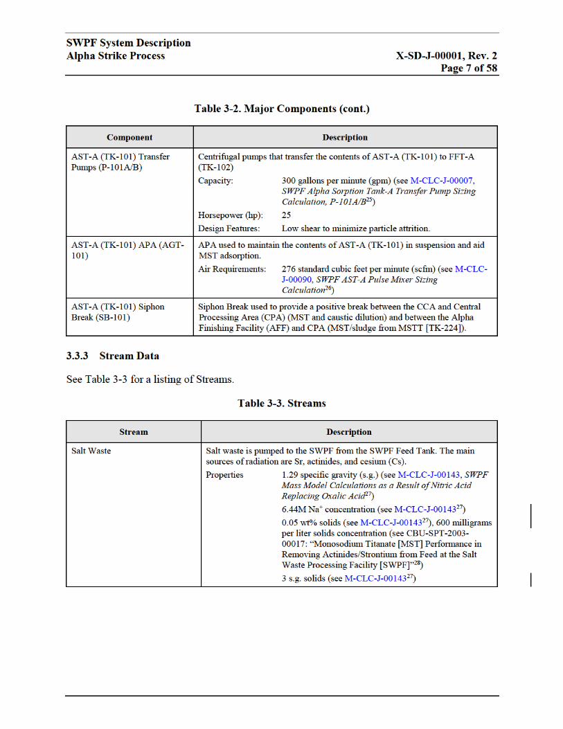
3.1 System Functions ...................................................................................................5 3.2 Operational Overview ...........................................................................................5 3.3 Configuration Information ...................................................................................6
3.3.1 Description of System ................................................................................6 3.3.2 Major Components ....................................................................................6
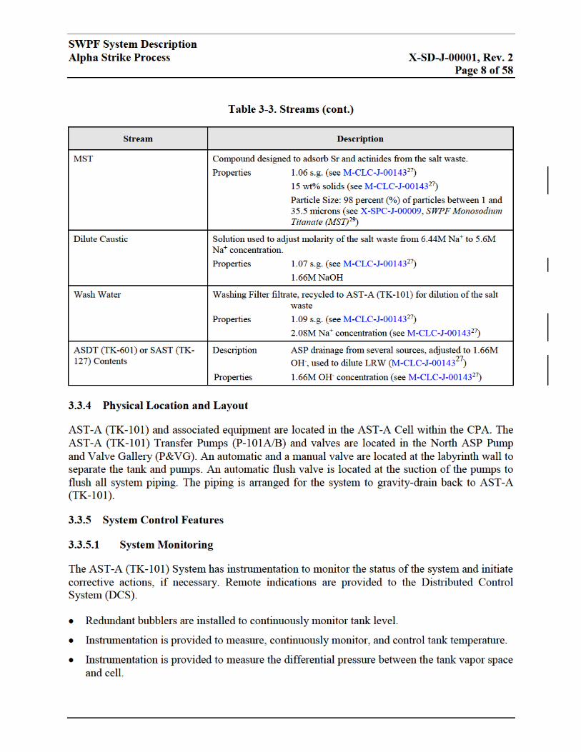
3.3.3 Stream Data ................................................................................................7 3.3.4 Physical Location and Layout ..................................................................8
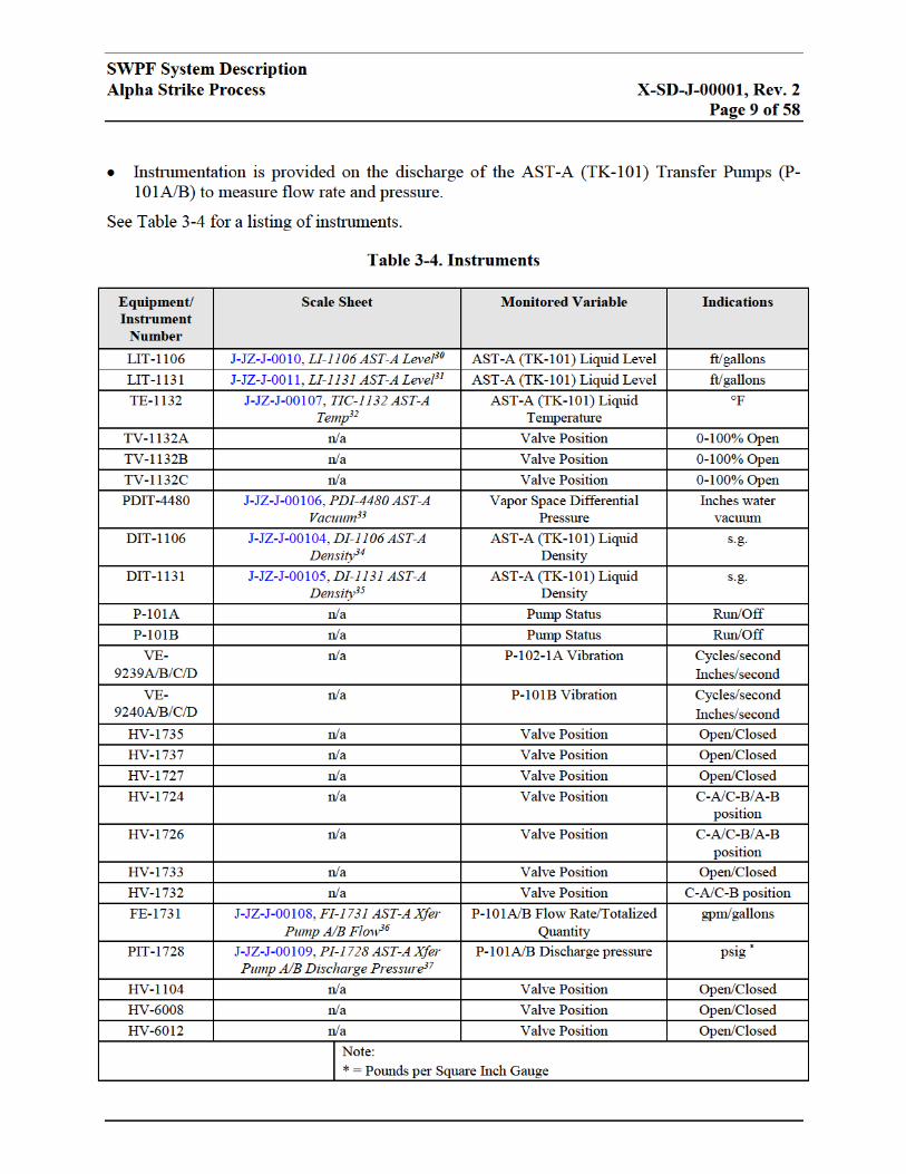
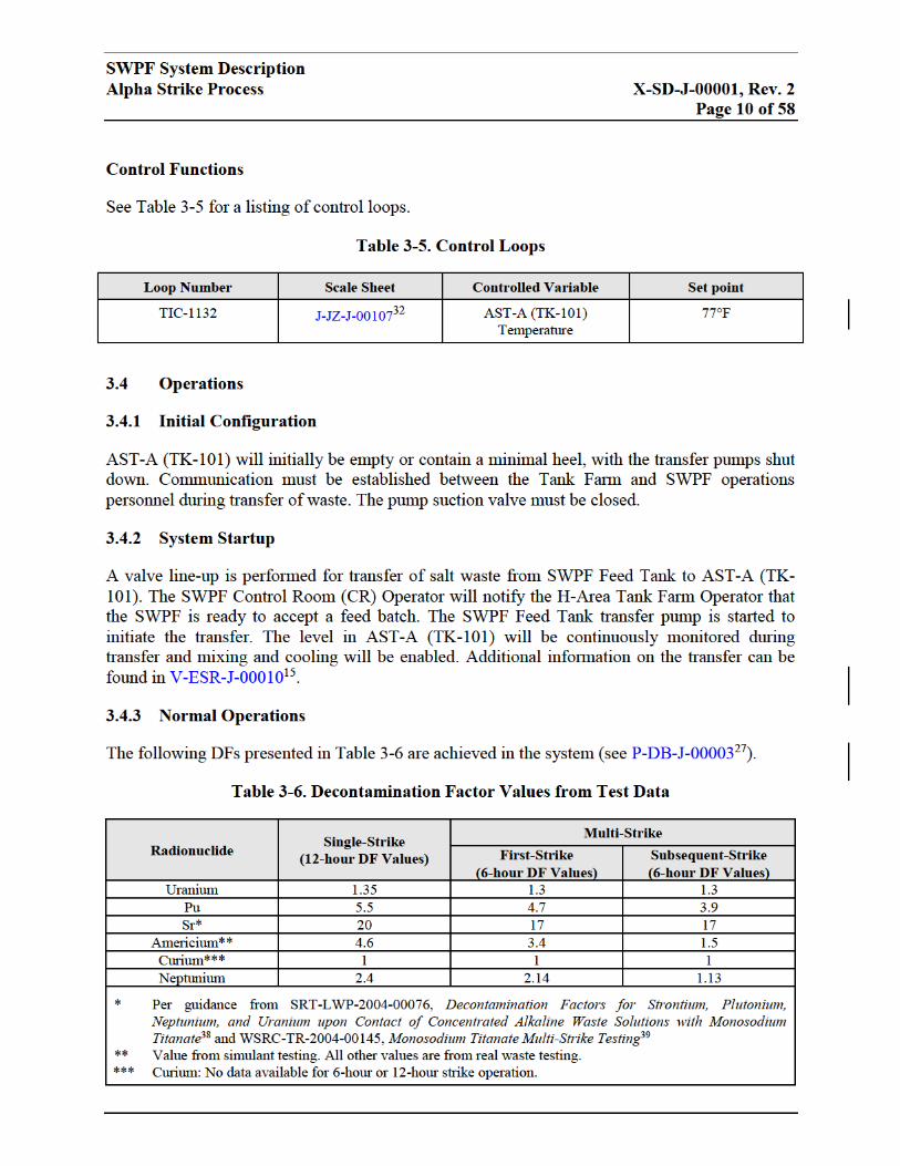
3.3.5 System Control Features ...........................................................................8 3.4 Operations ............................................................................................................10
3.4.1 Initial Configuration ................................................................................10
3.4.2 System Startup .........................................................................................10 3.4.3 Normal Operations ..................................................................................10
3.4.4 System Shutdown .....................................................................................13
4.0 FFT-A (TK-102) ...............................................................................................................13
4.1 System Functions .................................................................................................13
4.2 Operational Overview .........................................................................................13
4.3 Configuration Information .................................................................................13 4.3.1 Description of System ..............................................................................13 4.3.2 Major components ...................................................................................14
4.3.3 Stream Data ..............................................................................................16 4.3.4 Physical Location and Layout ................................................................16 4.3.5 System Control Features .........................................................................16
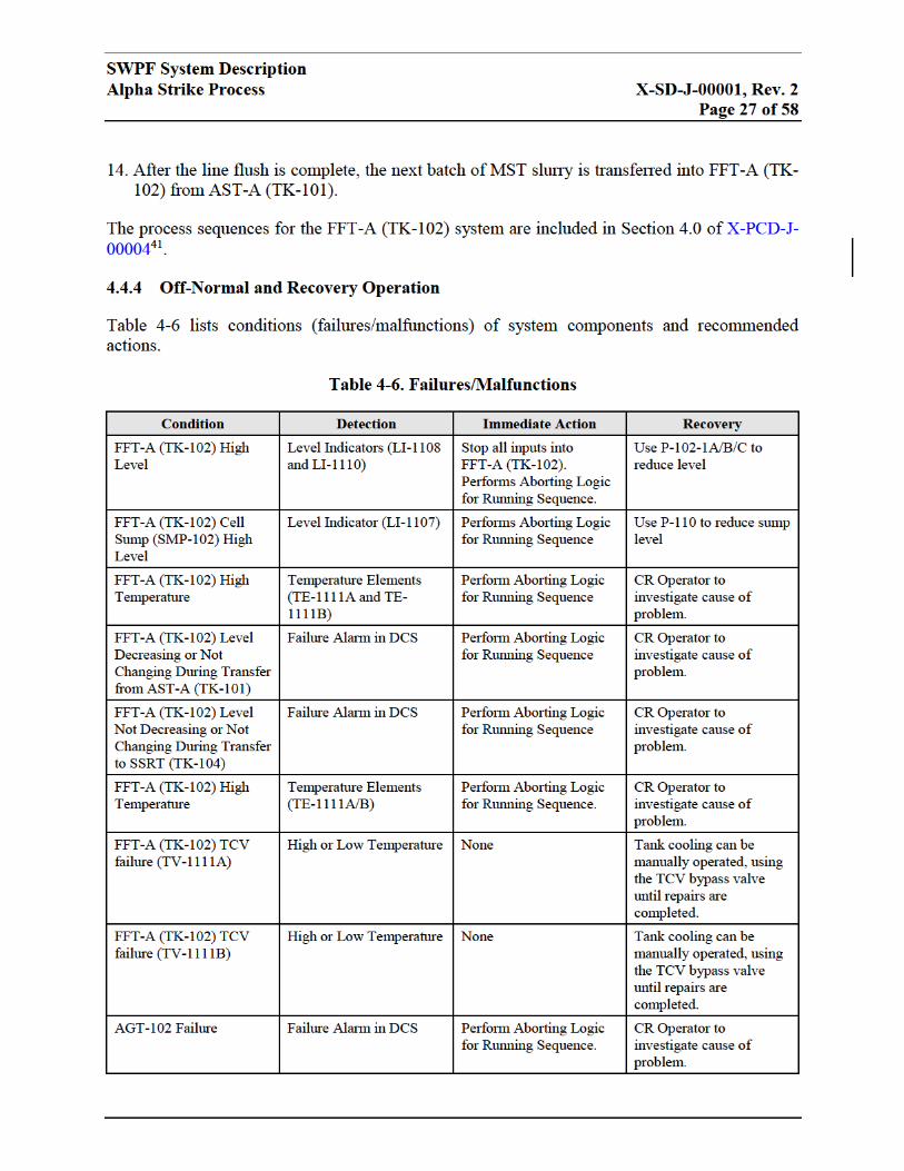
4.4 Operations ............................................................................................................25 4.4.1 Initial Configuration ................................................................................25 4.4.2 System Startup .........................................................................................25 4.4.3 Normal Operations ..................................................................................25 4.4.4 Off-Normal and Recovery Operation ....................................................27
4.4.5 System Shutdown .....................................................................................29
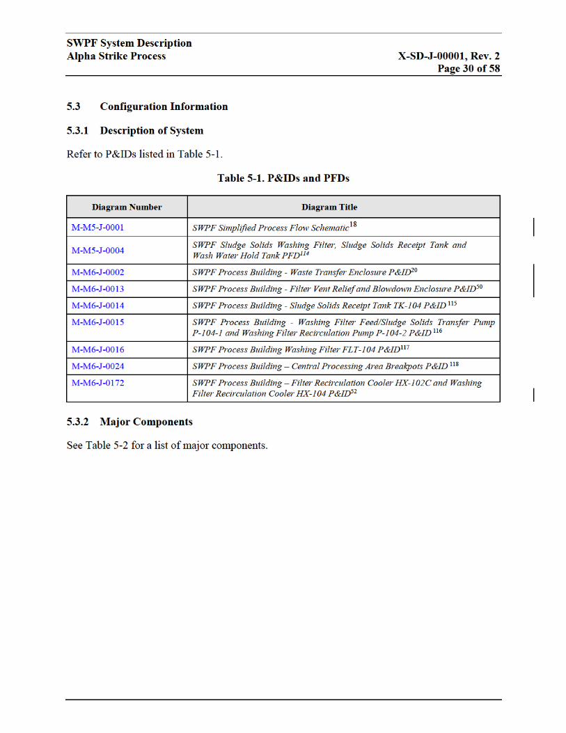
5.0 SSRT (TK-104) .................................................................................................................29
5.1 System Functions .................................................................................................29 5.2 Operational Overview .........................................................................................29
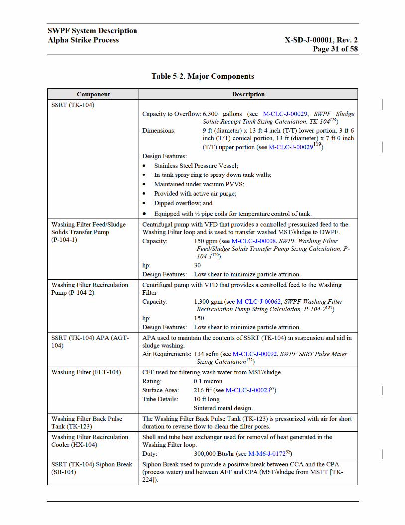
5.3 Configuration Information .................................................................................30 5.3.1 Description of System ..............................................................................30 5.3.2 Major Components ..................................................................................30
5.3.3 Stream Data ..............................................................................................32
SWPF System Description
Alpha Strike Process X-SD-J-00001, Rev. 2
Table of Contents
TABLE OF CONTENTS (cont.)
5.3.4 Physical Location and Layout ................................................................32 5.3.5 System Control Features .........................................................................32
5.4 Operations ............................................................................................................36 5.4.1 Initial Configuration ................................................................................36 5.4.2 System Startup .........................................................................................36 5.4.3 Normal Operations ..................................................................................37
5.4.4 Off-Normal and Recovery Operation ....................................................37 5.4.5 System Shutdown .....................................................................................39
6.0 WWHT (TK-105) .............................................................................................................39
6.1 System Functions .................................................................................................39
6.2 Operational Overview .........................................................................................40 6.3 Configuration Information .................................................................................40
6.3.1 Description of System ..............................................................................40
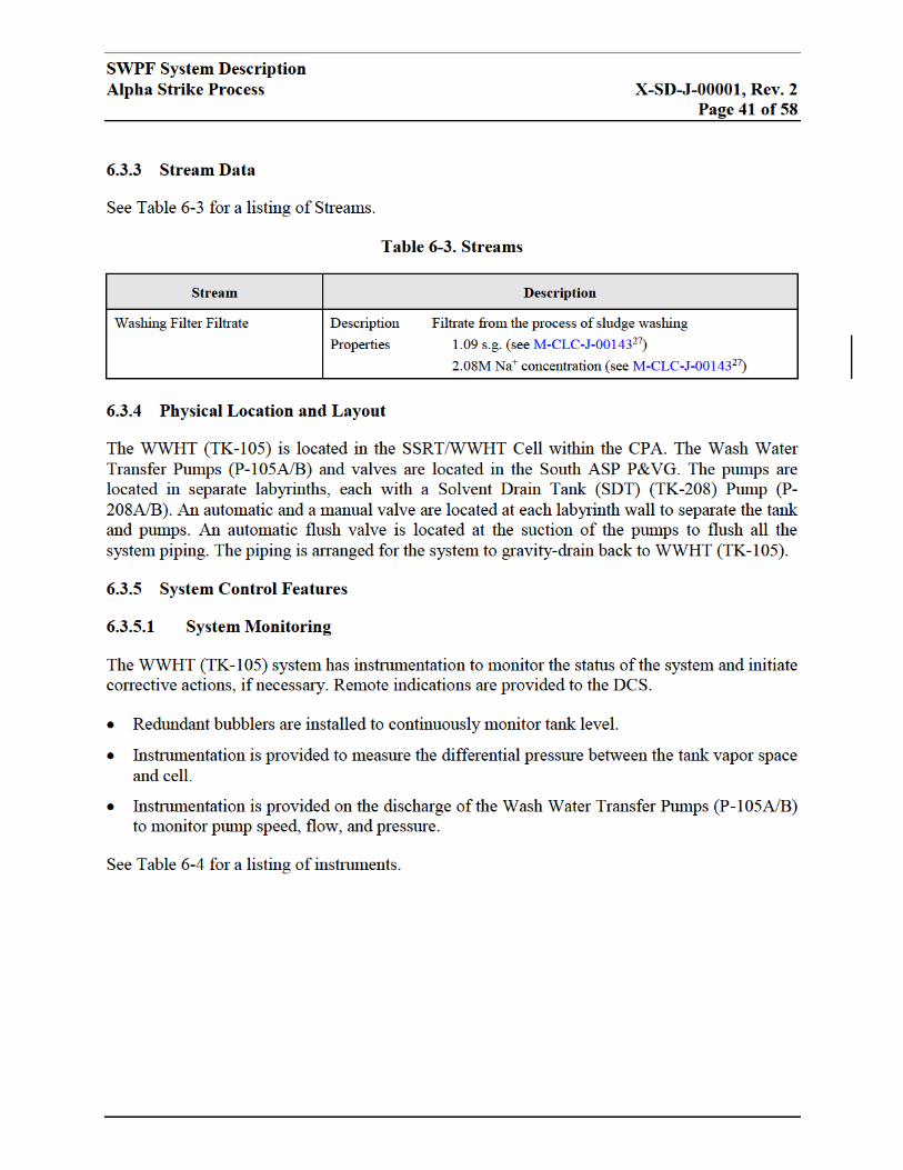
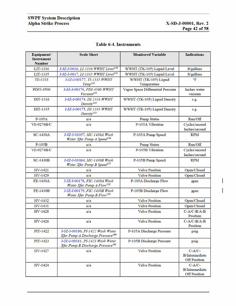
6.3.2 Major Components ..................................................................................40 6.3.3 Stream Data ..............................................................................................41
6.3.4 Physical Location and Layout ................................................................41 6.3.5 System Control Features .........................................................................41
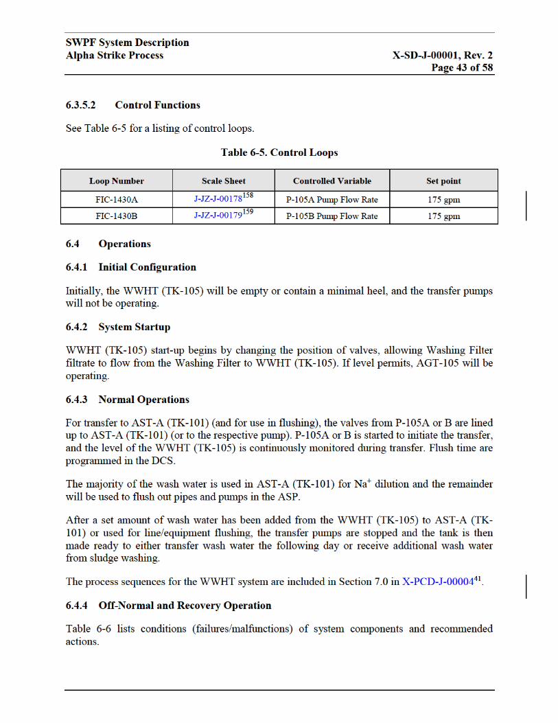
6.4 Operations ............................................................................................................43
6.4.1 Initial Configuration ................................................................................43 6.4.2 System Startup .........................................................................................43
6.4.3 Normal Operations ..................................................................................43 6.4.4 Off-Normal and Recovery Operation ....................................................43
6.4.5 System Shutdown .....................................................................................44
7.0 CSDT-A (TK-103) ............................................................................................................44
7.1 System Functions .................................................................................................44
7.2 Operational Overview .........................................................................................44 7.3 Configuration Information .................................................................................45
7.3.1 Description of System ..............................................................................45 7.3.2 Major Components ..................................................................................45 7.3.3 Stream Data ..............................................................................................45
7.3.4 Physical Location and Layout ................................................................46 7.3.5 System Control Features .........................................................................46
7.4 Operations ............................................................................................................47 7.4.1 Initial Configuration ................................................................................47
7.4.2 System Startup .........................................................................................47 7.4.3 Normal Operations ..................................................................................48 7.4.4 Off-Normal and Recovery Operation ....................................................48 7.4.5 System Shutdown .....................................................................................49
REFERENCES .............................................................................................................................49
SWPF System Description
Alpha Strike Process X-SD-J-00001, Rev. 2
Table of Contents
TABLE OF CONTENTS (cont.)
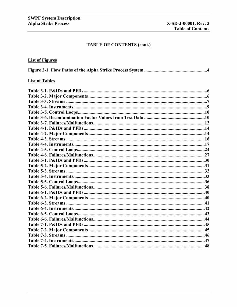
List of Figures
Figure 2-1. Flow Paths of the Alpha Strike Process System ......................................................4
List of Tables
Table 3-1. P&IDs and PFDs ..........................................................................................................6
Table 3-2. Major Components ......................................................................................................6 Table 3-3. Streams .........................................................................................................................7
Table 3-4. Instruments...................................................................................................................9 Table 3-5. Control Loops .............................................................................................................10
Table 3-6. Decontamination Factor Values from Test Data ....................................................10 Table 3-7. Failures/Malfunctions ................................................................................................12
Table 4-1. P&IDs and PFDs ........................................................................................................14 Table 4-2. Major Components ....................................................................................................14 Table 4-3. Streams .......................................................................................................................16
Table 4-4. Instruments.................................................................................................................17 Table 4-5. Control Loops .............................................................................................................24 Table 4-6. Failures/Malfunctions ................................................................................................27
Table 5-1. P&IDs and PFDs ........................................................................................................30 Table 5-2. Major Components ....................................................................................................31
Table 5-3. Streams .......................................................................................................................32
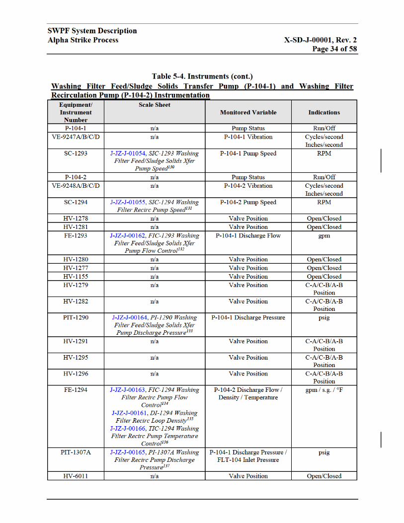
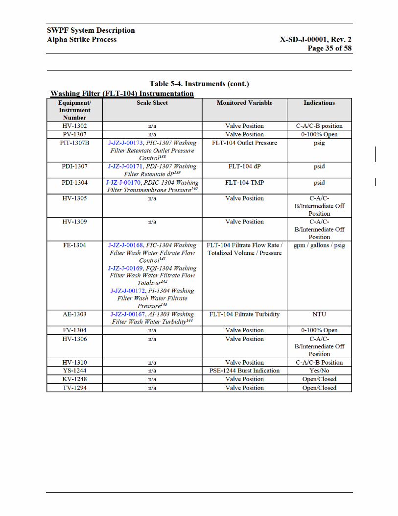
Table 5-4. Instruments.................................................................................................................33
Table 5-5. Control Loops .............................................................................................................36 Table 5-6. Failures/Malfunctions ................................................................................................38 Table 6-1. P&IDs and PFDs ........................................................................................................40
Table 6-2. Major Components ....................................................................................................40 Table 6-3. Streams .......................................................................................................................41
Table 6-4. Instruments.................................................................................................................42 Table 6-5. Control Loops .............................................................................................................43 Table 6-6. Failures/Malfunctions ................................................................................................44
Table 7-1. P&IDs and PFDs ........................................................................................................45 Table 7-2. Major Components ....................................................................................................45 Table 7-3. Streams .......................................................................................................................46
Table 7-4. Instruments.................................................................................................................47 Table 7-5. Failures/Malfunctions ................................................................................................48
SWPF System Description
Alpha Strike Process X-SD-J-00001, Rev. 2
Acronyms and Abbreviations
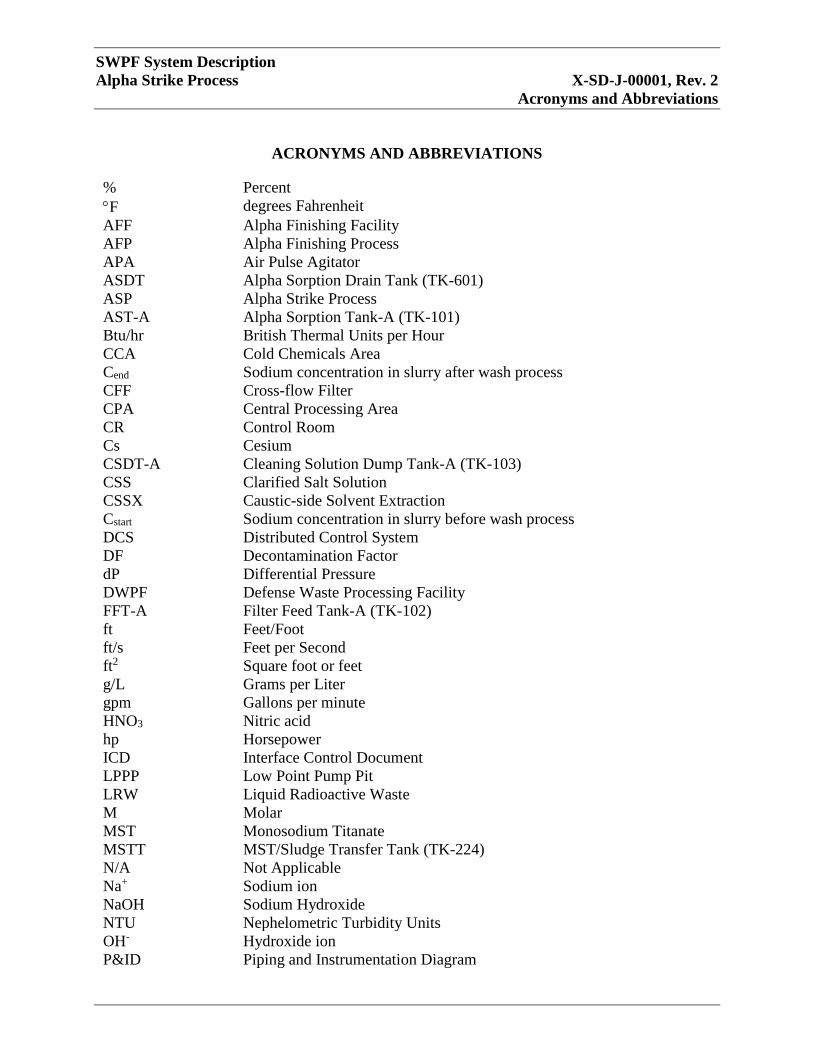
ACRONYMS AND ABBREVIATIONS
% Percent
F degrees Fahrenheit
AFF Alpha Finishing Facility
AFP Alpha Finishing Process
APA Air Pulse Agitator
ASDT Alpha Sorption Drain Tank (TK-601)
ASP Alpha Strike Process
AST-A Alpha Sorption Tank-A (TK-101)
Btu/hr British Thermal Units per Hour
CCA Cold Chemicals Area
Cend Sodium concentration in slurry after wash process
CFF Cross-flow Filter
CPA Central Processing Area
CR Control Room
Cs Cesium
CSDT-A Cleaning Solution Dump Tank-A (TK-103)
CSS Clarified Salt Solution
CSSX Caustic-side Solvent Extraction
Cstart Sodium concentration in slurry before wash process
DCS Distributed Control System
DF Decontamination Factor
dP Differential Pressure
DWPF Defense Waste Processing Facility
FFT-A Filter Feed Tank-A (TK-102)
ft Feet/Foot
ft/s Feet per Second
ft2 Square foot or feet
g/L Grams per Liter
gpm Gallons per minute
HNO3 Nitric acid
hp Horsepower
ICD Interface Control Document
LPPP Low Point Pump Pit
LRW Liquid Radioactive Waste
M Molar
MST Monosodium Titanate
MSTT MST/Sludge Transfer Tank (TK-224)
N/A Not Applicable
Na+ Sodium ion
NaOH Sodium Hydroxide
NTU Nephelometric Turbidity Units
OH- Hydroxide ion
P&ID Piping and Instrumentation Diagram
SWPF System Description
Alpha Strike Process X-SD-J-00001, Rev. 2
Acronyms and Abbreviations
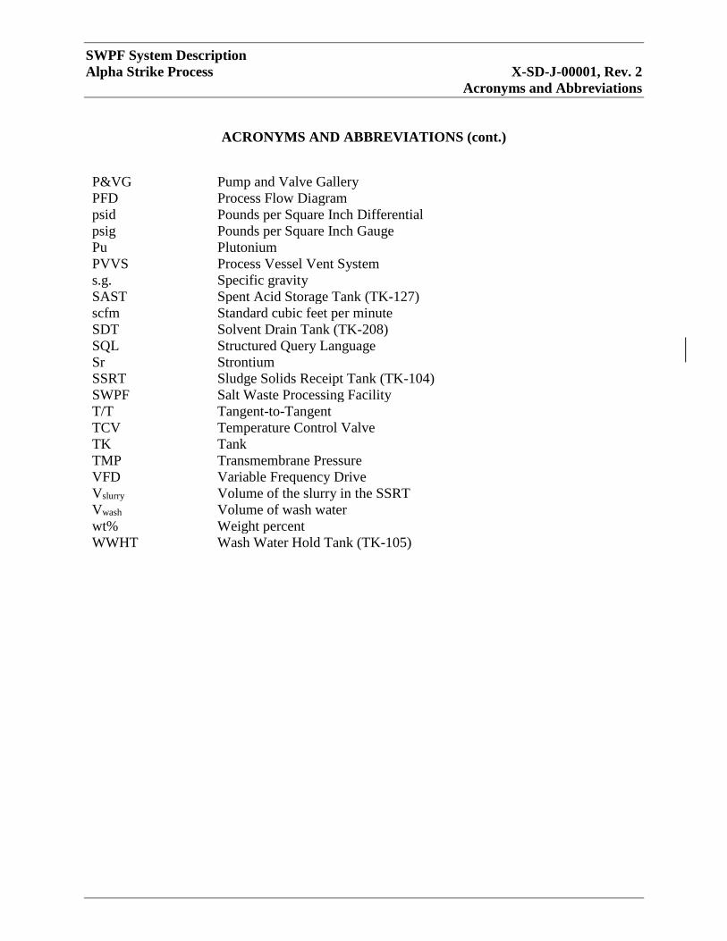
ACRONYMS AND ABBREVIATIONS (cont.)
P&VG Pump and Valve Gallery
PFD Process Flow Diagram
psid Pounds per Square Inch Differential
psig Pounds per Square Inch Gauge
Pu Plutonium
PVVS Process Vessel Vent System
s.g. Specific gravity
SAST Spent Acid Storage Tank (TK-127)
scfm Standard cubic feet per minute
SDT Solvent Drain Tank (TK-208)
SQL Structured Query Language
Sr Strontium
SSRT Sludge Solids Receipt Tank (TK-104)
SWPF Salt Waste Processing Facility
T/T Tangent-to-Tangent
TCV Temperature Control Valve
TK Tank
TMP Transmembrane Pressure
VFD Variable Frequency Drive
Vslurry Volume of the slurry in the SSRT
Vwash Volume of wash water
wt% Weight percent
WWHT Wash Water Hold Tank (TK-105)
SWPF System Description
Alpha Strike Process X-SD-J-00001, Rev. 2
Definitions/Glossary
DEFINITIONS/GLOSSARY
There are no definitions or glossary items for this System Description.
SWPF System Description
Alpha Strike Process X-SD-J-00001, Rev. 2
Page 1 of 58
1.0 SCOPE
The scope of this System Description is the Salt Waste Processing Facility (SWPF) Alpha Strike
Process (ASP) and related equipment.
The ASP can be divided into five subsystems:
1. Alpha Sorption Tank-A (AST-A) (TK-101) System – functions include receiving and storing
incoming liquid radioactive waste (LRW) from the Tank Farm, striking with Monosodium
Titanate (MST) to allow actinide and strontium (Sr) sorption, and transferring the MST slurry
to Filter Feed Tank-A (FFT-A) (TK-102) for filtration;
2. FFT-A (TK-102) System – functions include receiving MST slurry for filtration and
producing concentrated MST/sludge and clarified salt solution by filtering the MST slurry
received from AST-A (TK-101);
3. Sludge Solids Receipt Tank (SSRT) (TK-104) System – functions include receiving and
washing MST/sludge from FFT-A (TK-102) and the MST/Sludge Transfer Tank (MSTT)
(TK-224) and producing washed MST/sludge for the Defense Waste Processing Facility
(DWPF) and wash water filtrate;
4. Wash Water Hold Tank (WWHT) (TK-105) System – primary function is to receive, store,
and transfer the Washing Filter filtrate to AST-A (TK-101) for batch makeup; and
5. Cleaning Solution Dump Tank-A (CSDT-A) (TK-103) System – functions include receiving
and storing cleaning chemicals from the Cold Chemicals Area (CCA) and circulating
cleaning solutions through the filter to remove debris from the filter pores that are not
dislodged by back pulse cleaning.
The ASP system interfaces with components in the following System Descriptions:
E-SD-J-00002, SWPF Electrical System Description1;
J-SD-J-00002, SWPF Instrumentation and Controls System Description2;
M-SD-J-00005, SWPF Utilities System Description3;
X-SD-J-00002, SWPF Caustic-Side Solvent Extraction System Description4;
X-SD-J-00003, SWPF Cold Chemicals Area System Description5;
X-SD-J-00004, SWPF Alpha Finishing Process System Description6;
X-SD-J-00005, SWPF Drains System Description7;
X-SD-J-00006, SWPF Sampling System Description8;
X-SD-J-00007, SWPF Air Pulse Agitator System Description9; and
X-SD-J-00009, SWPF Caustic-side Solvent Extraction with Next Generation Solvent (NGS)
System Description10
SWPF System Description
Alpha Strike Process X-SD-J-00001, Rev. 2
Page 2 of 58
The safety analysis requirements related to system functions for this system are documented in
Chapter 4 (Safety Structures, Systems and Components) of S-SAR-J-00002, SWPF Documented
Safety Analysis11.
The safety analysis requirements related to operability for this system are documented in Chapter
5 (Derivation of Technical Safety Requirements) of S-SAR-J-0000211.
The discreet project design requirements for this system are documented in P-DB-J-00002,
Design Criteria Database12.
As part of the maintenance of the SWPF Master Equipment List (See PP-EN-5042, Master
Equipment List13), all permanent plant equipment is assigned a unique tag number. Each
component (equipment, instrumentation, specialty item, etc.) is assigned to one (and only one)
CSE system code. Structured Query Language (SQL) reports are generated (real time) off the
controlled Master Equipment List. These are filterable by CSE system. A complete listing of all
components associated with this system can be found using the following reports, and filtering
by HVAC:
MEL Cables;
MEL Equipment;
MEL Instruments;
MEL Lines;
MEL Manual Valves; and
MEL Specialty Items.
Similarly, all essential and support drawings are coded to the appropriate CSE system code (with
only one code allowed per drawing). Using the following link: Drawing Category Status, a report
may be generated for HVAC and selecting the drawing type (Essential, Support). Reference
drawings are not assigned System Codes and not required to be maintained current with facility
modifications per PP-EN-5001, Design Control13 and P-CDM-J-00001, Configuration
Management Plan14.
2.0 GENERAL OVERVIEW
Figure 2-1 is a schematic showing the main process equipment and flow paths of the ASP
System.
LRW is received in AST-A (TK-101) from the Tank Farm at 0.05 weight percent (wt%) solids.
In AST-A (TK-101), the sodium ion (Na+) concentration is reduced by using recycled caustic or
fresh dilute caustic. After dilution, MST is added to strike the waste and remove Sr and actinides,
with the solids concentration increasing to 0.07 wt%. After a set period of time, the treated waste
is transferred to FFT-A (TK-102) for filtration. The filtrate is sent to the Caustic-side Solvent
Extraction (CSSX) for further processing. After seven batches have been filtered, the waste with
a solids concentration between 5 and 7 wt% is transferred to SSRT (TK-104) for sludge washing.
SWPF System Description
Alpha Strike Process X-SD-J-00001, Rev. 2
Page 3 of 58
The filtrate is sent to WWHT (TK-105) to be used for dilution in AST-A (TK-101). The washed
sludge is transferred to DWPF for further processing.
NOTE: All process parameters should be interpreted as nominal values. Variations in
incoming waste characteristics (e.g. low solids concentrations) are expected during
operation of the facility.

SWPF System Description
Alpha Strike Process X-SD-J-00001, Rev. 2
Page 5 of 58
3.0 AST-A (TK-101)
3.1 System Functions
AST-A (TK-101) receives LRW from the Tank Farm for processing through the Waste Transfer
Enclosure. Refer to V-ESR-J-00010, SWPF Waste Transfer Interface Control Document [ICD-
10]15 for a representation of the overall flow paths to/from the SWPF. AST-A (TK-101)
performs the following functions:
Receives 23,200-gallon batches of LRW from the Tank Farm every 21.6 hours, resulting in
an instantaneous design capacity of 9.4 million gallons per year (see P-DB-J-00003: SWPF
Process Basis of Design16);
Dilutes the incoming LRW from Na+ concentration of 6.44 Molar (M) to 5.6M Na+, using
one or more of the following (see P-DB-J-0000316):
1.66M caustic from the Caustic Dilution Feed Tank (CDFT) (TK-108);
Wash Water from the WWHT (TK-105); and/or
ASP drainage from the Alpha Sorption Drain Tank (ASDT) (TK-601) or Spent Acid
Storage Tank (SAST) (TK-127) adjusted to 1.66M hydroxide ion (OH-) (see P-DB-J-
0000316);
Adds MST at 0.4 grams per liter (g/L) to strike/adsorb actinides and Sr;
Cools and maintains the tank contents at 77 degrees Fahrenheit (°F) (±5°F) for optimal MST
adsorption (see P-DB-J-0000316);
Provides uniform suspension of tank contents, using air pulse agitators (APAs) (see X-SD-J-
000079); and
Transfers the contacted MST/sludge to FFT-A (TK-102), following the prescribed reaction
duration (see P-DB-J-0000316).
3.2 Operational Overview
LRW in AST-A (TK-101) is diluted by using wash water from the WWHT (TK-105), caustic
dilution from the CDFT (TK-108), and/or spent filter cleaning caustic or miscellaneous drainage
from the ASDT (TK-601) or SAST (TK-127). The concentration of at least 1.66M sodium
hydroxide (NaOH) is used to maintain the hydroxide activity and to prevent aluminum
precipitation. A Na+ concentration of 5.6M is desired for optimal adsorption kinetics between the
MST, plutonium (Pu), and Sr (see WSRC-RP-99-00006: Bases and Assumptions, and Results of
the Flowsheet Calculations for the Decision Phase Salt Disposition Alternatives17). MST is then
added to strike the adjusted LRW to adsorb Sr and actinides. The MST is added to achieve a
concentration of 0.4 g/L. This concentration has been shown to rapidly adsorb Pu and Sr to the
required decontamination factor (DF) (see WSRC-RP-99-0000617). After the prescribed
adsorption period, the contents are transferred to FFT-A (TK-102) for filtration, using AST-A
(TK-101) Transfer Pumps (P-101A/B).


SWPF System Description
Alpha Strike Process X-SD-J-00001, Rev. 2
Page 11 of 58
Approximately 23,200 gallons of waste are transferred into AST-A (TK-101). The Na+
concentration of the waste received is reduced from 6.44M to 5.6M, using dilute caustic from
one or more of the following: wash water from the WWHT (TK-105) or caustic from the ASDT
(TK-601) or SAST (TK-127) and dilute caustic from the CDFT (TK-108). If available, the
contents of ASDT (TK-601) and SAST (TK-127) are used first, followed by the WWHT (TK-
105), and then the CDFT (TK-108). An algorithm in the DCS will determine the quantities of
each tank to add, based on volumes and compositions, with priority given to the ASDT (TK-
601). The dilution increases the rate of Sr and actinide adsorption (see HLW-PRE-2002-0019,
Alpha Removal/Caustic Side Solvent Extraction Material Balance Calculations with
Monosodium Titanate and Sodium Permanganate Alternatives40).
MST is added to AST-A (TK-101) through a siphon break (SB-101) to achieve a concentration
of 0.4g/L. The MST transfer line is flushed with dilute caustic from the CDFT (TK-108). The
tank contents are maintained in suspension, using the AST-A (TK-101) APA (AGT-101) (see X-
SD-J-000079). The Sr and actinides adsorb onto the MST. Strike time is 12 hours for single strike
and 6 hours for multiple strikes. Total batch time in AST-A (TK-101) is 21.6 hours for runs
requiring only one MST strike, or 15.6 hours for runs requiring an additional strike in the AFF.
Macro-batches of SWPF feed are qualified by sampling of either the SWPF feed tank or the
upstream blend tanks. Additionally, sampling is performed downstream as part of the Alpha
Finishing Process (AFP). As a result, sampling is not routinely performed from AST-A (TK-
101).
After the strike, the Operator selects the transfer pump, P-101A or B, to be used, and the contents
are pumped to FFT-A (TK-102). P-101A/B stops at the minimum pump operating level. After
transfer, the transfer pumps and discharge line are flushed with wash water.
The process sequences for the AST-A (TK-101) system are included in Section 3.0 of X-PCD-J-
00004, SWPF Automation Functional Control Sequence for: Alpha Strike Process41.Off-Normal
and Recovery Operation
Table 3-7 lists conditions (failures/malfunctions) of system components and recommended
actions.

SWPF System Description
Alpha Strike Process X-SD-J-00001, Rev. 2
Page 13 of 58
from the suction side. The flush valve is a three-way, three-flow position valve, allowing the line
to be flushed back to the tank and for the pump and downstream piping to be flushed. Flushing is
intended to reduce the dose rate sufficiently to allow personnel entry into the labyrinths. If
leakage has occurred, the labyrinth itself will need to be flushed, using the provided spray
system.
3.4.4 System Shutdown
Refer to the shutdown section of each sequence above for the details on each shutdown.
4.0 FFT-A (TK-102)
4.1 System Functions
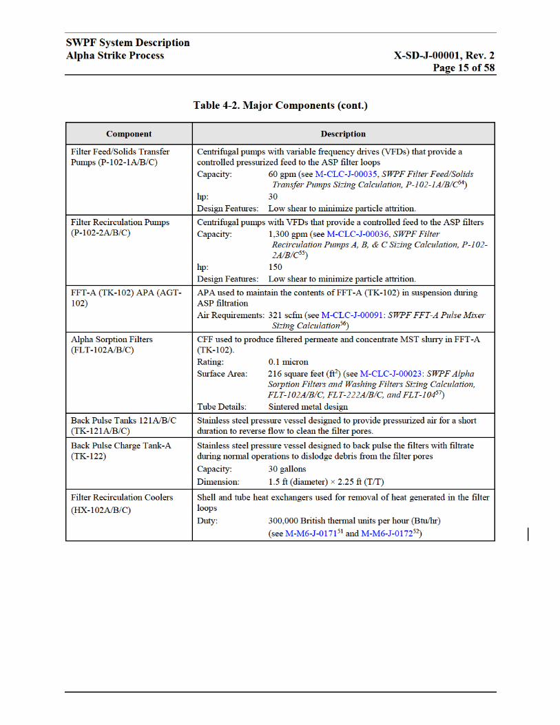
The FFT-A (TK-102) performs the following functions:
Cools and maintains the tank and filter loop contents at 73°F (±5°F) to minimize solids
precipitation downstream of the filters (see P-DB-J-0000316);
Filters tank contents down to a nominal maximum of 7 wt% solids (see M-CLC-J-0014327);
Provides uniform suspension of tank contents, using APAs (see X-SD-J-000079); and
Transfers concentrated MST/sludge to the SSRT (TK-104) after seven batches have been
concentrated (seeP-DB-J-0000316).
4.2 Operational Overview
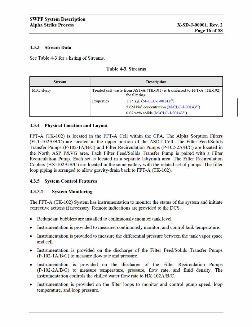
FFT-A (TK-102) receives MST slurry from AST-A (TK-101). The MST slurry is filtered by
using cross-flow filters (CFFs) and a two-pump system. The Filter Feed/Solids Transfer Pumps
(P-102-1A/B/C) provide pressure and a constant feed to the filter loop, while the Filter
Recirculation Pumps (P-102-2A/B/C) constantly circulate solution through the Alpha Sorption
Filters (FLT-102A/B/C). FFT-A (TK-102) stages the MST/sludge until seven batches of slurry
have been dewatered. The filtrate containing Cs is transferred to the CSSX for further
processing. The concentrated MST/sludge is transferred to the SSRT (TK-104) for washing.
4.3 Configuration Information
4.3.1 Description of System
Refer to P&IDs and PFDs listed in Table 4-1.


SWPF System Description
Alpha Strike Process X-SD-J-00001, Rev. 2
Page 25 of 58
4.4 Operations
4.4.1 Initial Configuration
FFT-A (TK-102) will initially be empty or contain a minimal heel with the feed and recirculation
pumps shut down, and mixing and cooling will be enabled. The pump suction valves must be
closed. The FFT-A (TK-102) System operation begins with opening of the respective pump
suction and discharge valves, pumping MST slurry from AST-A (TK-101) to FFT-A (TK-102).
If there is a significant deviation between the transfer volume and the tank level, the transfer is
terminated.
4.4.2 System Startup
The FFT-A (TK-102) filtration sequence will be initiated on completion of the AST-A (TK-101)
to FFT-A (TK-102) transfer. The Operator selects the two filter circuits to be used and the mode
of filter operation (either TMP or Filtrate Flow Control), and the circuit is switched into fully
automatic control.
The two selected filtration circuits are then filled with MST slurry by operating the respective
Filter Feed/Solids Transfer Pumps (P-102-1A/B/C) for a set time period before starting the Filter
Recirculation Pumps (P-102-2A/B/C). The filtrate control valve is open during filling to permit
circuit venting.
The recirculation pumps (P-102-2A/B/C) for the two selected filters are started at low speed to
establish recirculation before ramping up to full speed. The filtrate and slurry return valves are
throttled to establish the required TMP or flow set points. Chilled water is available to the filter
recirculation coolers (HX-102A/B/C) to start removing pump heat from the system, if needed.
Initially, the filtrate is routed back to FFT-A (TK-102). When the filtrate discharge is within
required turbidity parameters, filtrate discharge is directed to the CSSX.
4.4.3 Normal Operations
1. Recirculation is maintained through two CFFs at a specific rate by controlling the speed of
the Recirculation Pump (P-102-2A/B/C) to maintain a tube velocity in the range of 9 to 13
feet per second (ft/s) within the CFF bundle.
2. During the TMP Control mode of operation, the slurry return control valve and the
Feed/Solids Transfer Pump (P-102-1A/B/C) are operated to maintain the desired filter TMP
and maintain flow into the filter loop. The Feed Recirculation Pump (P-102-2A/B/C) is
controlled to maintain a constant flow rate (velocity) of feed through the filter tubes. No
throttling is performed on the filtrate line and the filtrate flow rate produced is variable.
3. In the Filtrate Flow Control mode of operation, the filter TMP varies as the circuit conditions
change during MST slurry concentration. The filtrate flow control valve modulates its
position to maintain the desired Operator-specified filtrate flow rate. The slurry return line

SWPF System Description
Alpha Strike Process X-SD-J-00001, Rev. 2
Page 26 of 58
control valve modulates during this mode, but should not close off the recirculation
completely.
4. During normal operation, each operating CFF can be back pulsed via a back pulse tank to
dislodge debris from the filter pores. When back pulsing is initiated, the filtrate flow is
momentarily reversed through the filter by opening an air valve connected to the pressurized
back pulse tank. The filtrate control valve is closed for the duration of the back pulse. The
pulse then takes place, after which the filtrate control valve reopens to its normal operating
position.
5. Back pulse cleaning is initiated as needed by the CR Operator.
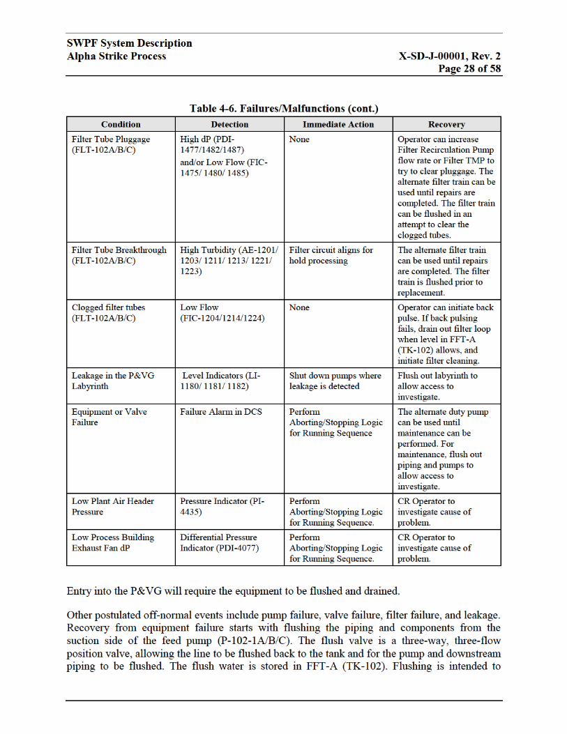
6. When back pulsing fails to restore the filtrate flux rate, the filter must be chemically cleaned.
The standby filter is placed into service and the affected filter drained and isolated. The FFT-
A (TK-102) level must be low to permit draining. The fouled filter is cleaned by the
circulation of cleaning solutions through the filter, as described in Section 7.0.
7. As the MST slurry is dewatered, the level in FFT-A (TK-102) falls. At a predetermined level
in FFT-A (TK-102), dewatering is stopped by placing the filtration circuits on hold. This
entails continuing to transfer slurry into and out of the filter loop, and recirculating MST
slurry around the filter circuits, but with the filtrate control valves positioned so that no
further concentration of the slurry can take place.
8. The next batch of MST slurry is added into FFT-A (TK-102) from AST-A (TK-101),
followed by a line flush. The new batch of slurry is added on top of the MST/sludge
concentrate remaining from Steps 1 to 7 above. The filter circuit is placed back on-line by
positioning the filtrate control valves so that dewatering can continue. Dewatering takes
place until the level has fallen to the same level identified in Step 7 above. Although the final
level in FFT-A (TK-102) is the same as the target level established in Step 7, the average
concentration of wt% solids is now greater.
9. Upon receipt of the seventh batch to FFT-A (TK-102), a sample is taken in order to
determine the final dewatering endpoint.
10. When the MST slurry concentration approaches the pre-determined level for operation of a
single filter, the DCS places the filter circuit with the lowest filtrate flow rate on hold (the
main circuit contents continue to recirculate, but with the filtrate discharge line isolated) and
then shut down. When the FFT-A (TK-102) concentration endpoint is reached, the slurry is
now termed MST/sludge, and the remaining filter circuit is placed on hold and the
dewatering process ceases. The circuit is then shut down and the contents are allowed to
drain back to FFT-A (TK-102).
11. The concentrated MST/sludge is then transferred from FFT-A (TK-102) to the SSRT (TK-
104). One of three Filter Feed/Solids Transfer Pumps (P-102-1A/B/C) is used for the
transfer, with the slurry discharge valves aligned to the SSRT (TK-104).
12. During the FFT-A (TK-102) to SSRT (TK-104) transfer, AST-A (TK-101) contents cannot
be transferred to the FFT-A (TK-102).
13. On completion of MST/sludge transfer to the SSRT (TK-104), the line is flushed with wash
water supplied from the WWHT (TK-105).
SWPF System Description
Alpha Strike Process X-SD-J-00001, Rev. 2
Page 29 of 58
reduce the dose rate sufficiently to allow personnel entry into the labyrinths. If leakage has
occurred, the labyrinth itself will need to be flushed, using the installed spray system.
4.4.5 System Shutdown
Shutdown of the FFT-A (TK-102) system includes stopping pumps and operating equipment.
The tank, pumps, and process lines are drained and flushed, and isolation valves are closed.
5.0 SSRT (TK-104)
5.1 System Functions
The SSRT (TK-104) performs the following functions:
Receive MST/sludge from the FFT-A (TK-102),
Cool and maintain the tank and filter loop contents at 77°F (±5°F),
Wash the tank contents down to 0.5M Na+ (see P-DB-J-0000316),
Provides uniform suspension of tank contents, using APAs (see X-SD-J-000079), and
Stores washed MST/sludge and transfers the washed MST/sludge to DWPF (seeP-DB-J-
0000316).
5.2 Operational Overview
Sludge washing occurs in the SSRT (TK-104), using process water and cross-flow filtration. The
MST/sludge is received from the FFT-A (TK-102) and/or from the MSTT (TK-224). As process
water is added, the MST/sludge is filtered to remove excess Na+. The process water addition rate,
based on ideal mixing, is set to equal the filtrate rate, and the filtrate is routed to the WWHT
(TK-105). The volume of process water used is equivalent to the initial MST/sludge volume
multiplied by the natural log of the initial sodium concentration and divided by the final sodium
concentration (see M-CLC-J-0002327).
Vwash = Vslurry ln (Cstart/Cend), (1)
The washed sludge is transferred to DWPF for further processing.


SWPF System Description
Alpha Strike Process X-SD-J-00001, Rev. 2
Page 37 of 58
5.4.3 Normal Operations
1. In TMP control, the process water flow rate to the SSRT (TK-104) is set to match the filtrate
flow rate. In filtrate flow control, the process water flow rate is set to the controlled filtrate
flow rate. Because tank volume is being maintained constant and soluble species
concentrations are being removed in the filtrate stream, the wt% solids of the insoluble
species in the SSRT (TK-104) increases marginally.
2. Totalized filtrate flow rate is monitored to predict the endpoint of MST/sludge washing.
3. Recirculation is maintained through the CFF at a specific rate by controlling the speed of the
Recirculation Pump (P-104-2) to maintain a tube velocity in the range of 9 to 13 ft/s in the
CFF bundle.
4. The Washing Filter Feed/Sludge Solids Transfer Pump (P-104-1), in conjunction with a
MST/sludge return valve, modulates to control the TMP/flow in the circuit.
5. During normal operation, the CFF is back pulsed with filtrate, via a back pulse tank, to
dislodge debris from the filter pores. Filtrate flow is reversed back through the filter by a
pressurized air supply.
6. Back pulse cleaning is initiated by the CR Operator.
7. If back pulsing fails to restore filtrate flux, the filter is chemically cleaned. The filter is
drained and then cleaned by circulating cleaning solutions through the filter, as described in
Section 7.0.
8. The total water addition to SSRT (TK-104) and totalized filtrate volume are monitored to
determine the completion of sludge washing.
9. The washed MST/sludge is transferred to DWPF, using P-104-1. AGT-104 will be shut down
when the minimum level for APA operation is reached. The line internal to the labyrinth is
flushed with wash water after the transfer, and the line to DWPF is vented to the SAST (TK-
127) headspace.
The process sequences for the SSRT system are included in Section 6.0 in X-PCD-J-0000441.
5.4.4 Off-Normal and Recovery Operation
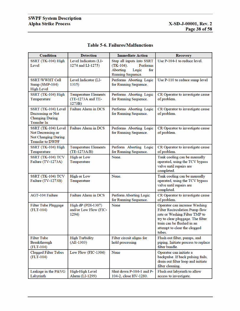
Table 5-6 lists conditions (failures/malfunctions) of system components and recommended
actions.


SWPF System Description
Alpha Strike Process X-SD-J-00001, Rev. 2
Page 49 of 58
7.4.5 System Shutdown
Shutdown of the CSDT-A (TK-103) system includes stopping pumps and operating equipment.
The tank, pumps, and process lines are drained and flushed and isolation valves are closed.
REFERENCES
1 E-SD-J-00002, Salt Waste Processing Facility Project Electrical System Description.
Parsons, Aiken, South Carolina.
2 J-SD-J-00002, Salt Waste Processing Facility Project Instrumentation and Controls System
Description. Parsons, Aiken, South Carolina.
3 M-SD-J-00005, Salt Waste Processing Facility Project Utilities System Description. Parsons,
Aiken, South Carolina.
4 X-SD-J-00002, Salt Waste Processing Facility Project Caustic-Side Solvent Extraction
System Description. Parsons, Aiken, South Carolina.
5 X-SD-J-00003, Salt Waste Processing Facility Project Cold Chemical Area System
Description. Parsons, Aiken, South Carolina.
6 X-SD-J-00004, Salt Waste Processing Facility Project Alpha Finishing Process System
Description. Parsons, Aiken, South Carolina.
7 X-SD-J-00005, SWPF Drains System Description. Parsons, Aiken, South Carolina.
8 X-SD-J-00006, Salt Waste Processing Facility Project Sampling System Description.
Parsons, Aiken, South Carolina.
9 X-SD-J-00007, Salt Waste Processing Facility Project Air Pulse Agitator System
Description. Parsons, Aiken, South Carolina.
10 X-SD-J-00007, SWPF Caustic-side Solvent Extraction with Next Generation Solvent (NGS)
System Description. Parsons, Aiken, South Carolina.
11 S-SAR-J-00002, SWPF Documented Safety Analysis. Parsons, Aiken, South Carolina.
12 P-DB-J-00002, Design Criteria Database. Parsons, Aiken, South Carolina.
13 Salt Waste Processing Facility Project Procedures Manual. Parsons, Aiken, South Carolina.
14 P-CDM-J-00001, Configuration Management Manual. Parsons, Aiken, South Carolina.
15 V-ESR-J-00010, Salt Waste Processing Facility Project Waste Transfer Interface Control
Document (ICD-10), Revision 6. Parsons, Aiken, South Carolina.

SWPF System Description
Alpha Strike Process X-SD-J-00001, Rev. 2
Page 50 of 58
16 P-DB-J-00003, Salt Waste Processing Facility Project Process Basis of Design. Parsons,
Aiken, South Carolina.
17 WSRC-RP-99-00006, Bases and Assumptions, and Results of the Flowsheet Calculations for
the Decision Phase Salt Disposition Alternatives, Revision 3. Authors: Dimenna, R.A., et al.
Westinghouse Savannah River Company, Aiken, South Carolina. May 2001.
18 M-M5-J-0001, SWPF Simplified Process Flow Schematic. Parsons, Aiken, South Carolina.
19 M-M5-J-0002, SWPF Feed Receipt, Alpha Sorption Tank-A, Filter Feed Tank-A, and
Cleaning Solution Dump Tank-A PFD. Parsons, Aiken, South Carolina.
20 M-M6-J-0002, SWPF Process Building - Waste Transfer Enclosure P&ID. Parsons, Aiken,
South Carolina.
21 M-M6-J-0005, SWPF Process Building - Alpha Sorption Tank-A TK-101 P&ID. Parsons,
Aiken, South Carolina.
22 M-M6-J-0006, SWPF Process Building - Alpha Sorption Tank-A Transfer Pumps P-101A/B
P&ID. Parsons, Aiken, South Carolina.
23 M-M6-J-0025, SWPF Process Building – Central Processing Area Breakpots P&ID.
Parsons, Aiken, South Carolina.
24 M-CLC-J-00026, SWPF Alpha Sorption Tank A Sizing Calculation, TK-101, Revision 1.
Parsons, Aiken, South Carolina.
25 M-CLC-J-00007, SWPF Alpha Sorption Tank-A Transfer Pumps Sizing Calculation, P-
101A/B, Revision 2. Parsons, Aiken, South Carolina.
26 M-CLC-J-00090, SWPF AST-A Pulse Mixer Sizing Calculation, Revision 2. Parsons, Aiken,
South Carolina.
27 M-CLC-J-00143, SWPF Mass Balance Model Calculations as a Result of Nitric Acid
Replacing Oxalic Acid, Revision 1. Parsons, Aiken, South Carolina.
28 “Monosodium Titanate (MST) Performance in Removing Actinides/Strontium from Feed at
the Salt Waste Processing Facility (SWPF)”, PE-03-166. Letter from Painter, G.W.
(DOE-SR) to Charles H. Terhune III (Parsons), dated February 6, 2003, and attachment,
“Suggested Design Basis for SWPF Feed – Conceptual Design Phase”, CBU-SPT-2003-
00017, Revision 0, Internal WSRC Memorandum from Edwards, R.E. to H.H. Elder, dated
February 3, 2003.
29 X-SPC-J-00009, SWPF Monosodium Titanate (MST), Revision 3. Parsons, Aiken, South
Carolina.
SWPF System Description
Alpha Strike Process X-SD-J-00001, Rev. 2
Page 51 of 58
30 J-JZ-J-0010, LI-1106 AST-A Level. Parsons, Aiken, South Carolina.
31 J-JZ-J-0011, LI-1131 AST-A Level. Parsons, Aiken, South Carolina.
32 J-JZ-J-00107, TIC-1132 AST-A Temp. Parsons, Aiken, South Carolina.
33 J-JZ-J-00106, PDI-4480 AST-A Vacuum. Parsons, Aiken, South Carolina.
34 J-JZ-J-00104, DI-1106 AST-A Density. Parsons, Aiken, South Carolina.
35 J-JZ-J-00105, DI-1131 AST-A Density. Parsons, Aiken, South Carolina.
36 J-JZ-J-00108, FI-1731 AST-A Xfer Pump A/B Flow. Parsons, Aiken, South Carolina.
37 J-JZ-J-00109, PI-1728 AST-A Xfer Pump A/B Discharge Pressure. Parsons, Aiken, South
Carolina.
38 SRT-LWP-2004-00076, Decontamination Factors for Strontium, Plutonium, Neptunium, and
Uranium upon Contact of Concentrated Alkaline Waste Solutions with Monosodium
Titanate, Revision 0. Savannah River Technology Center, South Carolina. May 19, 2004.
39 WSRC-TR-2004-00145, Monosodium Titanate Multi-Strike Testing, Revision 0. Authors:
Barnes, M.J., F.F. Fondeur, D.T. Hobbs, and S.D. Fink. Westinghouse Savannah River
Company, Aiken, South Carolina. April 29, 2004.
40 HLW-PRE-2002-0019, Alpha Removal/Caustic Side Solvent Extraction Material Balance
Calculations with Monosodium Titanate and Sodium Permanganate Alternatives, Revision 0.
Authors: Subosits, S.G. and S.G. Campbell. Westinghouse Savannah River Company, Aiken,
South Carolina. July 24, 2002.
41 X-PCD-J-00004, SWPF Automation Functional Control Sequences for: Alpha Strike
Process. Parsons, Aiken, South Carolina.
42 M-M5-J-0003, SWPF Alpha Sorption Filters FLT-102A/B/C PFD. Parsons, Aiken, South
Carolina.
43 M-M6-J-0007, SWPF Process Building - Filter Feed Tank-A TK-102 P&ID. Parsons, Aiken,
South Carolina.
44 M-M6-J-0008 SH1, SWPF Process Building - Filter Feed/Solids Transfer Pump P-102-1A
and Filter Recirculation Pump P-102-2A P&ID. Parsons, Aiken, South Carolina.
45 M-M6-J-0008 SH2, SWPF Process Building - Filter Feed/Solids Transfer Pump P-102-1B
and Filter Recirculation Pump P-102-2B P&ID. Parsons, Aiken, South Carolina.

SWPF System Description
Alpha Strike Process X-SD-J-00001, Rev. 2
Page 52 of 58
46 M-M6-J-0008 SH3, SWPF Process Building - Filter Feed/Solids Transfer Pump P-102-1C
and Filter Recirculation Pump P-102-2C P&ID. Parsons, Aiken, South Carolina.
47 M-M6-J-0010, SWPF Process Building - Alpha Sorption Filter FLT-102A P&ID. Parsons,
Aiken, South Carolina.
48 M-M6-J-0011, SWPF Process Building - Alpha Sorption Filter FLT-102B P&ID. Parsons,
Aiken, South Carolina.
49 M-M6-J-0012, SWPF Process Building - Alpha Sorption Filter FLT-102C P&ID. Parsons,
Aiken, South Carolina.
50 M-M6-J-0013, SWPF Process Building - Filter Vent Relief and Blowdown Enclosure P&ID.
Parsons, Aiken, South Carolina.
51 M-M6-J-0171, SWPF Process Building – Filter Recirculation Coolers HX-102A/B P&ID.
Parsons, Aiken, South Carolina
52 M-M6-J-0172, SWPF Process Building – Filter Recirculation Cooler HX-102C and Washing
Filter Recirculation Cooler HX-104 P&ID. Parsons, Aiken, South Carolina.
53 M-CLC-J-00027, SWPF Filter Feed Tank A Sizing Calculation, TK-102, Revision 1.
Parsons, Aiken, South Carolina.
54 M-CLC-J-00035, SWPF Filter Feed/Solids Transfer Pumps Sizing Calculation, P-102-
1A/B/C, Revision 1. Parsons, Aiken, South Carolina.
55 M-CLC-J-00036, SWPF Filter Recirculation Pumps A, B, & C Sizing Calculation, P-102-
2A/B/C, Revision 1. Parsons, Aiken, South Carolina.
56 M-CLC-J-00091, SWPF FFT-A Pulse Mixer Sizing Calculation, Revision 2. Parsons, Aiken,
South Carolina.
57 M-CLC-J-00023, SWPF Alpha Sorption Filters and Washing Filter Sizing Calculation, FLT-
102A/B/C, FLT-222A/B/C, and FLT-104, Revision 1. Parsons, Aiken, South Carolina.
58 J-JZ-J-0012, LI-1108 FFT-A Level. Parsons, Aiken, South Carolina.
59 J-JZ-J-0013, LI-1110 FFT-A Level. Parsons, Aiken, South Carolina.
60 J-JZ-J-00113, TIT-1111A FFT-A Tank Temperature. Parsons, Aiken, South Carolina.
61 J-JZ-J-01094, TIT-1111B FFT-A Tank Temperature. Parsons, Aiken, South Carolina.
62 J-JZ-J-00112, PDI-4490 FFT-A Vacuum. Parsons, Aiken, South Carolina.

SWPF System Description
Alpha Strike Process X-SD-J-00001, Rev. 2
Page 53 of 58
63 J-JZ-J-00110, DI-1108 FFT-A Density. Parsons, Aiken, South Carolina.
64 J-JZ-J-00111, DI-1110 FFT-A Density. Parsons, Aiken, South Carolina.
65 J-JZ-J-01045, SIC-1187 ASP Filter Feed/Solids Xfer Pump 1A Speed. Parsons, Aiken, South
Carolina.
66 J-JZ-J-01068, SIC-1475 ASP Filter Recirc Pump 2A Speed. Parsons, Aiken, South Carolina.
67 J-JZ-J-00117, FIC-1187 ASP Filter Feed/Solids Xfer Pump 1A Flow Control. Parsons,
Aiken, South Carolina.
68 J-JZ-J-00123, PI-1184 ASP Filter Feed/Solids Xfer Pump 1A Discharge Pressure. Parsons,
Aiken, South Carolina.
69 J-JZ-J-00120, FIC-1475 ASP Filter Recirc Pump 2A Flow Control. Parsons, Aiken, South
Carolina.
70 J-JZ-J-00114, DI-1475 ASP Filter A Recirc Loop Density. Parsons, Aiken, South Carolina.
71 J-JZ-J-00129, TIC-1475 ASP Filter Recirc Pump 2A Temperature Control. Parsons, Aiken,
South Carolina.
72 J-JZ-J-00126, PI-1477A ASP Filter Recirc Pump 2A Discharge Pressure. Parsons, Aiken,
South Carolina.
73 J-JZ-J-01047, SIC-1188 ASP Filter Feed/Solids Xfer Pump 1B Speed. Parsons, Aiken, South
Carolina.
74 J-JZ-J-01069, SIC-1480 ASP Filter Recirc Pump 2B Speed. Parsons, Aiken, South Carolina.
75 J-JZ-J-00118, FIC-1188 ASP Filter Feed/Solids Xfer Pump 1B Flow Control. Parsons,
Aiken, South Carolina.
76 J-JZ-J-00124, PI-1185 ASP Filter Feed/Solids Xfer Pump 1B Discharge Pressure. Parsons,
Aiken, South Carolina.
77 J-JZ-J-00121, FIC-1480 ASP Filter Recirc Pump 2B Flow Control. Parsons, Aiken, South
Carolina.
78 J-JZ-J-00115, DI-1480 ASP Filter B Recirc Loop Density. Parsons, Aiken, South Carolina.
79 J-JZ-J-00130, TIC-1480 ASP Filter Recirc Pump 2B Temperature Control. Parsons, Aiken,
South Carolina.

SWPF System Description
Alpha Strike Process X-SD-J-00001, Rev. 2
Page 54 of 58
80 J-JZ-J-00127, PI-1482A ASP Filter Recirc Pump 2B Discharge Pressure. Parsons, Aiken,
South Carolina.
81 J-JZ-J-01053, SIC-1189 ASP Filter Feed/Solids Xfer Pump 1C Speed. Parsons, Aiken, South
Carolina.
82 J-JZ-J-01070, SIC-1485 ASP Filter Recirc Pump 2C Speed. Parsons, Aiken, South Carolina.
83 J-JZ-J-00119, FIC-1189 ASP Filter Feed/Solids Xfer Pump 1C Flow Control. Parsons,
Aiken, South Carolina.
84 J-JZ-J-00125, PI-1186 ASP Filter Feed/Solids Xfer Pump 1C Discharge Pressure. Parsons,
Aiken, South Carolina.
85 J-JZ-J-00122, FIC-1485 ASP Filter Recirc Pump 2C Flow Control. Parsons, Aiken, South
Carolina.
86 J-JZ-J-00116, DI-1485 ASP Filter C Recirc Loop Density. Parsons, Aiken, South Carolina.
87 J-JZ-J-00131, TIC-1485 ASP Filter Recirc Pump 2C Temperature Control. Parsons, Aiken,
South Carolina.
88 J-JZ-J-00128, PI-1487A ASP Filter Recirc Pump 2C Discharge Pressure. Parsons, Aiken,
South Carolina.
89 J-JZ-J-00153, PIC-1477 ASP Filter A Retentate Outlet Pressure Control. Parsons, Aiken,
South Carolina.
90 J-JZ-J-00147, PDI-1477 ASP Filter A Retentate dP. Parsons, Aiken, South Carolina.
91 J-JZ-J-00144, PDIC-1204 ASP Filter A Transmembrane Pressure. Parsons, Aiken, South
Carolina.
92 J-JZ-J-00138, FIC-1204 ASP Filter A CSS Filtrate Flow Control. Parsons, Aiken, South
Carolina.
93 J-JZ-J-00141, FQI-1204 ASP Filter A CSS Filtrate Flow Totalizer. Parsons, Aiken, South
Carolina.
94 J-JZ-J-00150, PI-1204 ASP Filter A CSS Filtrate Pressure. Parsons, Aiken, South Carolina.
95 J-JZ-J-00132, AI-1201 ASP Filter A CSS Filtrate Turbidity. Parsons, Aiken, South Carolina.
96 J-JZ-J-00133, AI-1203 ASP Filter A CSS Filtrate Turbidity. Parsons, Aiken, South Carolina.
SWPF System Description
Alpha Strike Process X-SD-J-00001, Rev. 2
Page 55 of 58
97 J-JZ-J-00154, PIC-1482 ASP Filter B Retentate Outlet Pressure Control. Parsons, Aiken,
South Carolina.
98 J-JZ-J-00148, PDI-1482 ASP Filter B Retentate dP. Parsons, Aiken, South Carolina.
99 J-JZ-J-00145, PDIC-1214 ASP Filter B Transmembrane Pressure. Parsons, Aiken, South
Carolina.
100 J-JZ-J-00139, FIC-1214 ASP Filter B CSS Filtrate Flow Control. Parsons, Aiken, South
Carolina.
101 J-JZ-J-00142, FQI-1214 ASP Filter B CSS Filtrate Flow Totalizer. Parsons, Aiken, South
Carolina.
102 J-JZ-J-00151, PI-1214 ASP Filter B CSS Filtrate Pressure. Parsons, Aiken, South Carolina.
103 J-JZ-J-00134, AI-1211 ASP Filter B CSS Filtrate Turbidity. Parsons, Aiken, South Carolina.
104 J-JZ-J-00135, AI-1213 ASP Filter B CSS Filtrate Turbidity. Parsons, Aiken, South Carolina.
105 J-JZ-J-00155, PIC-1487 ASP Filter C Retentate Outlet Pressure Control. Parsons, Aiken,
South Carolina.
106 J-JZ-J-00149, PDI-1487 ASP Filter C Retentate dP. Parsons, Aiken, South Carolina.
107 J-JZ-J-00146, PDIC-1224 ASP Filter C Transmembrane Pressure. Parsons, Aiken, South
Carolina.
108 J-JZ-J-00140, FIC-1224 ASP Filter C CSS Filtrate Flow Control. Parsons, Aiken, South
Carolina.
109 J-JZ-J-00143, FQI-1224 ASP Filter C CSS Filtrate Flow Totalizer. Parsons, Aiken, South
Carolina.
110 J-JZ-J-00152, PI-1224 ASP Filter C CSS Filtrate Pressure. Parsons, Aiken, South Carolina.
111 J-JZ-J-00136, AI-1221 ASP Filter C CSS Filtrate Turbidity. Parsons, Aiken, South Carolina.
112 J-JZ-J-00137, AI-1223 ASP Filter C CSS Filtrate Turbidity. Parsons, Aiken, South Carolina.
113 J-JZ-J-00156, PI-1256 ASP Back Pulse Charge Tank-A Pressure. Parsons, Aiken, South
Carolina.
114 M-M5-J-0004, SWPF Sludge Solids Washing Filter, Sludge Solids Receipt Tank and Wash
Water Hold Tank PFD. Parsons, Aiken, South Carolina.

SWPF System Description
Alpha Strike Process X-SD-J-00001, Rev. 2
Page 56 of 58
115 M-M6-J-0014, SWPF Process Building - Sludge Solids Receipt Tank TK-104 P&ID. Parsons,
Aiken, South Carolina.
116 M-M6-J-0015, SWPF Process Building - Washing Filter Feed/Sludge Solids Transfer Pump
P-104-1 and Washing Filter Recirculation Pump P-104-2 P&ID. Parsons, Aiken, South
Carolina.
117 M-M6-J-0016, SWPF Process - Building Washing Filter FLT-104 P&ID. Parsons, Aiken,
South Carolina.
118 M-M6-J-0024, SWPF Process Building – Central Processing Area Breakpots P&ID.
Parsons, Aiken, South Carolina.
119 M-CLC-J-00029, SWPF Sludge Solids Receipt Tank Sizing Calculation, TK-104, Revision 1.
Parsons, Aiken, South Carolina.
120 M-CLC-J-00008, SWPF Washing Filter Feed/Sludge Solids Transfer Pump Sizing
Calculation, P-104-1, Revision 1. Parsons, Aiken, South Carolina.
121 M-CLC-J-00062, SWPF Washing Filter Recirculation Pump Sizing Calculation, P-104-2,
Revision 1. Parsons, Aiken, South Carolina.
122 M-CLC-J-00092, SWPF SSRT Pulse Mixer Sizing Calculation, Revision 2. Parsons, Aiken,
South Carolina.
123 J-JZ-J-0014, LI-1274 SSRT Level. Parsons, Aiken, South Carolina.
124 J-JZ-J-0015, LI-1275 SSRT Level. Parsons, Aiken, South Carolina.
125 J-JZ-J-00160, TIT-1273A SSRT Tank Temperature. Parsons, Aiken, South Carolina.
126 J-JZ-J-01095, TIT-1273B SSRT Tank Temperature. Parsons, Aiken, South Carolina.
127 J-JZ-J-00159, PDI-4510 SSRT Vacuum. Parsons, Aiken, South Carolina.
128 J-JZ-J-00157, DI-1274 SSRT Density. Parsons, Aiken, South Carolina.
129 J-JZ-J-00158, DI-1275 SSRT Density. Parsons, Aiken, South Carolina.
130 J-JZ-J-01054, SIC-1293 Washing Filter Feed/Sludge Solids Xfer Pump Speed. Parsons,
Aiken, South Carolina.
131 J-JZ-J-01055, SIC-1294 Washing Filter Recirc Pump Speed. Parsons, Aiken, South Carolina.
132 J-JZ-J-00162, FIC-1293 Washing Filter Feed/Sludge Solids Xfer Pump Flow Control.
Parsons, Aiken, South Carolina.

SWPF System Description
Alpha Strike Process X-SD-J-00001, Rev. 2
Page 57 of 58
133 J-JZ-J-00164, PI-1290 Washing Filter Feed/Sludge Solids Xfer Pump Discharge Pressure.
Parsons, Aiken, South Carolina.
134 J-JZ-J-00163, FIC-1294 Washing Filter Recirc Pump Flow Control. Parsons, Aiken, South
Carolina.
135 J-JZ-J-00161, DI-1294 Washing Filter Recirc Loop Density. Parsons, Aiken, South Carolina.
136 J-JZ-J-00166, TIC-1294 Washing Filter Recirc Pump Temperature Control. Parsons, Aiken,
South Carolina.
137 J-JZ-J-00165, PI-1307A Washing Filter Recirc Pump Discharge Pressure. Parsons, Aiken,
South Carolina.
138 J-JZ-J-00173, PIC-1307 Washing Filter Retentate Outlet Pressure Control. Parsons, Aiken,
South Carolina.
139 J-JZ-J-00171, PDI-1307 Washing Filter Retentate dP. Parsons, Aiken, South Carolina.
140 J-JZ-J-00170, PDIC-1304 Washing Filter Transmembrane Pressure. Parsons, Aiken, South
Carolina.
141 J-JZ-J-00168, FIC-1304 Washing Filter Wash Water Filtrate Flow Control. Parsons, Aiken,
South Carolina.
142 J-JZ-J-00169, FQI-1304 Washing Filter Wash Water Filtrate Flow Totalizer. Parsons, Aiken,
South Carolina.
143 J-JZ-J-00172, PI-1304 Washing Filter Wash Water Filtrate Pressure. Parsons, Aiken, South
Carolina.
144 J-JZ-J-00167, AI-1303 Washing Filter Wash Water Turbidity. Parsons, Aiken, South
Carolina.
145 M-M6-J-0017, SWPF Process Building - Wash Water Hold Tank TK-105 P&ID. Parsons,
Aiken, South Carolina.
146 M-M6-J-0018, SWPF Process Building - Wash Water Transfer Pumps P-105A/B P&ID.
Parsons, Aiken, South Carolina.
147 M-CLC-J-00030, SWPF Wash Water Hold Tank Sizing Calculation, TK-105, Revision 1.
Parsons, Aiken, South Carolina.
148 M-CLC-J-00009, SWPF Wash Water Transfer Pump P-105A/B Sizing Calculation, Revision
1. Parsons, Aiken, South Carolina.
SWPF System Description
Alpha Strike Process X-SD-J-00001, Rev. 2
Page 58 of 58
149 M-CLC-J-00093, SWPF WWHT Pulse Mixer Sizing Calculation, Revision 2. Parsons, Aiken,
South Carolina.
150 J-JZ-J-0016, LI-1316 WWHT Level. Parsons, Aiken, South Carolina.
151 J-JZ-J-0017, LI-1335 WWHT Level. Parsons, Aiken, South Carolina.
152 J-JZ-J-00177, TI-1333 WWHT Temp. Parsons, Aiken, South Carolina.
153 J-JZ-J-00176, PDI-4500 WWHT Vacuum. Parsons, Aiken, South Carolina.
154 J-JZ-J-00174, DI-1316 WWHT Density. Parsons, Aiken, South Carolina.
155 J-JZ-J-00175, DI-1335 WWHT Density. Parsons, Aiken, South Carolina.
156 J-JZ-J-01057, SIC-1430A Wash Water Xfer Pump A Speed. Parsons, Aiken, South Carolina.
157 J-JZ-J-01064, SIC-1430B Wash Water Xfer Pump B Speed. Parsons, Aiken, South Carolina.
158 J-JZ-J-00178, FIC-1430A Wash Water Xfer Pump A Flow. Parsons, Aiken, South Carolina.
159 J-JZ-J-00179, FIC-1430B Wash Water Xfer Pump B Flow. Parsons, Aiken, South Carolina.
160 J-JZ-J-00180, PI-1422 Wash Water Xfer Pump A Discharge Pressure. Parsons, Aiken, South
Carolina.
161 J-JZ-J-00181, PI-1423 Wash Water Xfer Pump B Discharge Pressure. Parsons, Aiken, South
Carolina.
162 M-M6-J-0019, SWPF Process Building - Cleaning Solution Dump Tank-A TK-103 P&ID.
Parsons, Aiken, South Carolina.
163 M-CLC-J-00028, SWPF Cleaning Solution Dump Tank A Sizing Calculation, TK-103,
Revision 1. Parsons, Aiken, South Carolina.
164 J-JZ-J-0006, LI-1411 CSDT-A Level. Parsons, Aiken, South Carolina.
165 J-JZ-J-0007, LI-1412 CSDT-A Level. Parsons, Aiken, South Carolina.
166 J-JZ-J-00185, TI-1410 CSDT-A Temp. Parsons, Aiken, South Carolina.
167 J-JZ-J-00184, PDI-1413 CSDT-A Vacuum. Parsons, Aiken, South Carolina.
168 J-JZ-J-00182, DI-1411 CSDT-A Density. Parsons, Aiken, South Carolina.
169 J-JZ-J-00183, DI-1412 CSDT-A Density. Parsons, Aiken, South Carolina.