Embed Size (px)
Citation preview

Home Signal Distribution Kit
Installation GuideSXHDK2
2
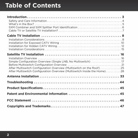
Table of Contents
Introduction . . . . . . . . . . . . . . . . . . . . . . . . . . . . . . . . . . . . . . . . . . . . . . . . . . . . 3Safety and Care Information . . . . . . . . . . . . . . . . . . . . . . . . . . . . . . . . . . . . . . . . . . . . . . . . . . .4What’s in the Box? . . . . . . . . . . . . . . . . . . . . . . . . . . . . . . . . . . . . . . . . . . . . . . . . . . . . . . . . . . . 5SXM Combiner and SXM Splitter Port Identification . . . . . . . . . . . . . . . . . . . . . . . . . . . . . . 6Cable TV or Satellite TV Installation? . . . . . . . . . . . . . . . . . . . . . . . . . . . . . . . . . . . . . . . . . . . 7
Cable TV Installation . . . . . . . . . . . . . . . . . . . . . . . . . . . . . . . . . . . . . . . . . . . . 8Installation Considerations . . . . . . . . . . . . . . . . . . . . . . . . . . . . . . . . . . . . . . . . . . . . . . . . . . . . 8Installation for Exposed CATV Wiring . . . . . . . . . . . . . . . . . . . . . . . . . . . . . . . . . . . . . . . . . 10Installation for Hidden CATV Wiring . . . . . . . . . . . . . . . . . . . . . . . . . . . . . . . . . . . . . . . . . . . 12Installation Considerations . . . . . . . . . . . . . . . . . . . . . . . . . . . . . . . . . . . . . . . . . . . . . . . . . . . 15
Satellite TV Installation . . . . . . . . . . . . . . . . . . . . . . . . . . . . . . . . . . . . . . . . . 16Installation Overview . . . . . . . . . . . . . . . . . . . . . . . . . . . . . . . . . . . . . . . . . . . . . . . . . . . . . . . . 16Simple Configuration Overview (Single LNB, No Multiswitch) . . . . . . . . . . . . . . . . . . . . 17Before Multiswitch Configuration Overview . . . . . . . . . . . . . . . . . . . . . . . . . . . . . . . . . . . . 21After Multiswitch Configuration Overview (Multiswitch on the Roof) . . . . . . . . . . . . . .25After Multiswitch Configuration Overview (Multiswitch Inside the Home) . . . . . . . . . .28
Antenna Installation . . . . . . . . . . . . . . . . . . . . . . . . . . . . . . . . . . . . . . . . . . . . 33
Troubleshooting . . . . . . . . . . . . . . . . . . . . . . . . . . . . . . . . . . . . . . . . . . . . . . . 44
Product Specifications . . . . . . . . . . . . . . . . . . . . . . . . . . . . . . . . . . . . . . . . . . 45
Patent and Environmental Information . . . . . . . . . . . . . . . . . . . . . . . . . . . . 45
FCC Statement . . . . . . . . . . . . . . . . . . . . . . . . . . . . . . . . . . . . . . . . . . . . . . . . 46
Copyrights and Trademarks . . . . . . . . . . . . . . . . . . . . . . . . . . . . . . . . . . . . . . 47

3
Introduction
Thank you for purchasing the Home Signal Distribution Kit for Cable or Satellite TV Plus Satellite Radio
The Home Signal Distribution Kit for Cable or Satellite TV Plus Satellite Radio will allow you to connect a Sirius or XM Radio using your existing TV RG-6 wiring . This allows you great flexibility as to where you locate the Outdoor Home Antenna and where you locate your Satellite Radio . A short adapter cable is included for adapting the RG-6 cable to your Satellite Radio .
This kit is compatible with DirecTV® (legacy & SWM), DISH® Network, cable TV, AT&T™ U-verse®, Verizon™ FiOS®, and off-air TV signals . In this Installation Guide, DirecTV and DISH Network are referred to as satellite TV . All others are referred to as cable TV or CATV .
The Outdoor Home Antenna is a high-performance antenna, specifically designed to receive signals from the SiriusXM satellites and terrestrial (ground) transmitters when mounted outdoors on a home or other building, wall, pole, or roof . The antenna has been approved by Sirius XM Radio Inc . to receive the SiriusXM signal under a variety of conditions within the SiriusXM North American coverage area .
The antenna should be mounted according to the instructions in this manual to ensure the best quality reception of the SiriusXM signal . All necessary mounting hardware for a variety of mounting options is included with the kit .
And for the latest information about this and other SiriusXM products and accessories, visit www .siriusxm .com or your favorite retailer .
Please read the entire Installation Guide before installing your Home Signal Distribution Kit for Cable or Satellite TV Plus Satellite Radio.

4
Introduction
Safety and Care Information IMPORTANT! Always read and understand all the instructions to avoid injury to yourself and/or damage to your device . Sirius XM Radio Inc . disclaims all responsibility for damage from data loss due to breakdown, repair, or other
causes .
•Review this installation manual before beginning the installation process . Installation of the Outdoor Home Antenna, SXM Combiner and SXM Splitter requires experience in mechanical and electrical procedures, and may involve using a ladder to reach the soffit or roof of the home or building . A phillips-type screwdriver and a 3/8 in . wrench is needed for installation, and, depending upon the type of installation, a power drill with a 3/32 in . drill bit may also be required . If you are not comfortable or experienced with the installation procedures, SiriusXM recommends that you have a professional install the kit and wiring for you .
• Be sure not to cut, damage, or puncture the external jacket of the antenna cables during the installation procedure . Damage to the antenna cable can cause the SiriusXM signal to be degraded or unavailable, and can also cause water to intrude into the antenna cable causing the cable to fail .
•Do not expose devices to chemicals such as benzene and thinners . Do not use liquid or aerosol cleaners . Clean with a soft damp cloth only .
•Do not expose devices to fire, flame, or other heat sources .• Do not try to disassemble and/or repair devices yourself .• Do not drop the devices or subject them to severe impact .• Do not place heavy objects on devices .• Do not subject devices to excessive pressure .

5
What’s in the Box?
C
D
H
I
J
K
L
F
G
A
B
E
TO SPLITTER
SXHDK1Satellite Radio & TV Combiner System
Combiner (Outdoor)
TVIN
SXMIN
TO COMBINER
SXHDK1Satellite Radio & TV Combiner System
Splitter (Indoor)
PowerTV
OUTSXMOUT
SYSTEMSELECT
SAT
TV
CATV
A. Outdoor Home AntennaB. Antenna BaseC. SXM Combiner & Screws (2)D. SXM Splitter & Screws (2)E . AC Power AdapterF. Rubber Cable Boot
G. RG-174 Adapter CableH. U-Bolts (2)I. Mounting Brackets (2)J. Hex Lock Nuts (4)K. #10 Screws (4)L. Cable Tie
Introduction

6
SXM Combiner and SXM Splitter Port IdentificationFor a successful installation, the various cables used in the installation process described later in this manual must be connected to the correct ports on the SXM Combiner and SXM Splitter . The following illustration identifies the SXM Combiner and SXM Splitter, and the 3 ports on each . This diagram should be used for reference during installation . The SXM Splitter must be used nearest to the Satellite Radio.
SXM IN SXM OUT
TO SXM SPLITTER
TV IN TV OUT
TO SXM COMBINER
TO SPLITTER
SXHDK1Satellite Radio & TV Combiner System
Combiner (Outdoor)
TVIN
SXMIN
TO COMBINER
SXHDK1Satellite Radio & TV Combiner System
Splitter (Indoor)
PowerTV
OUTSXMOUT
SYSTEMSELECT
SAT
TV
CATV
SXM SPLITTERSXM COMBINER
Introduction

7
SXM Splitter (Side View)
POWER CONNECTOR
SAT TV Cable TV
SYSTEM SELECT SWITCH
The System Select Switch should be in the Cable TV position for cable TV, AT&T U-verse, Verizon FiOS, and off-air TV signals, and in the SAT TV position for DirecTV and DISH Network .
Cable TV or Satellite TV Installation?Instructions for cable TV begin on page 8, and for satellite TV begin on page 15 .
Once you have read the instructions and purchased the necessary cables for your installation, you can begin by installing the Outdoor Home Antenna as described beginning page 33 .
Introduction

8
The installation instructions in this section are for cable TV . If you have satellite TV, turn to page 15 .
Installation ConsiderationsIn order to install the antenna you will need to purchase several lengths of RG-6 antenna cables to complete your installation . The following illustration shows a typical home installation .
AdapterCable
DENKITCHEN
BEDROOM
GARAGE/WORKSHOP
SATELLITE RADIO
MASTER BEDROOM
CATV SPLITTER SXM SPLITTER
T�
T�T�
SXM COM�I�ER
T�
CATV
C
O�TDOOR �OME A�TE��A
� � � � � � � � � ������
����
�M
����
�
� � � � � � � � � ������
����
�M
����
�
S
Cable TV Installation

9
A CATV splitter takes the Cable TV service that comes into your home and splits the signal so that Cable TV service can be connected to two or more TVs in the different rooms in your home . In this manual, the CATV splitter is depicted as a 4-port splitter, however, the existing CATV splitter in your home may have 2, 3, 4, or more ports .
The CATV splitter is usually located near where the Cable TV wiring enters your home, which is typically in a garage, basement, or utility room . You’ll need to locate your CATV splitter in order to install the Home Distribution Kit .
You may need to purchase up to four separate RG-6 cables of the appropriate lengths to install your Home Signal Distribution Kit . The number of cables which will be needed is dependent upon how the existing CATV wiring is installed in your home . Some homes have exposed, surface mounted CATV wiring while others have the CATV wiring built into the walls with a CATV F-type connection jack in the room wall .
RG-6 cable is typically sold in short patch lengths, 3 or 6 ft ., and longer lengths of 25, 50, or 100 ft ., all with “F” type connectors on each end . These cables may be purchased at your local hardware store, home center, or electronics retailer .
The combined length of the RG-6 cables from the Outdoor Home Antenna to the Satellite Radio should not exceed 150 ft., as shown in the following illustrations. The overall length for your particular installation may be less than 150 ft .
Determine the overall length of the RG-6 cable run by measuring the distance from the Outdoor Home Antenna mounting location to where the SXM Combiner will be located . (It is recommended that the SXM Combiner be located indoors .) Next measure the distance from the SXM Combiner to where the SXM Splitter will be located . Then measure the distance from the
Cable TV Installation

10
SXM Splitter to the Satellite Radio and note that this particular cable length should not exceed 50 ft . Also include the length of cable from the CATV wall outlet to the SXM Splitter if your home has hidden wiring . The sum of these cable lengths should not exceed 150 ft.
Installation for Exposed CATV WiringFor homes having exposed wiring, cables will be needed for the following:
1. A length of RG-6 cable to go from the Outdoor Home Antenna to the location of the SXM Combiner .
2. A length of RG-6 cable to go from the CATV splitter to the SXM Combiner .
3. A length of RG-6 cable to go from the SXM Splitter to your TV .
4. A length of RG-6 cable to go from the SXM Splitter to your Satellite Radio . The length of this cable should not exceed 50 ft.
The cables which must be purchased are depicted in the following illustration as solid black, while existing cables are shown as gray .
Cable TV Installation
11
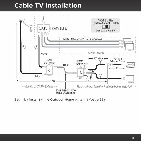
Begin by installing the Outdoor Home Antenna (page 33) .
RG-6
RG-6
1
EXISTING CATV RG-6 CABLES
CATV SplitterCATV
C
SXMCombiner SXM
Splitter
2
RG-6
RG-174Adapter Cable
S6”
3
4RG-6
Room where Satellite Radio is being Installed
Other Rooms
Vicinity of CATV SplitterEXISTING CATVRG-6 CABLING
150
50’ MAX
’
2 3 4 5 6 7 8 9 0 direct
jump
FM
menu
1
Set to Cable TV
SXM SplitterSystem Select Switch
Cable TV Installation

12
Installation for Hidden CATV WiringFor homes having hidden wiring, cables will be needed for the following:
1. A length of RG-6 cable to go from the Outdoor Home Antenna to the location of the SXM Combiner .
2. A length of RG-6 cable to go from the CATV splitter to the SXM Combiner .
3. A length of RG-6 cable to go from the CATV wall outlet connector to the SXM Splitter .
4. A length of RG-6 cable to go from the SXM Splitter to your Satellite Radio . The length of this cable should not exceed 50 ft.
The cables which must be purchased are depicted in the following illustration as solid black, while existing cables are shown as gray .
Cable TV Installation

13
SXMCombiner SXM
Splitter
RG-6S
RG-6
1
Room where Satellite Radio is being Installed
Other Rooms
Vicinity of CATV Splitter
RG-6
EXISTING CATV RG-6 CABLES
EXISTING CATV RG-6CABLING IN WALLS
CATV WALLOUTLET
CATV SplitterCATV
C6”
150’
2
4
3
RG-6
WA
LLW
ALL
RG-174Adapter Cable
50’ MAX
2 3 4 5 6 7 8 9 0 direct
jump
FM
menu
1
Set to Cable TV
SXM SplitterSystem Select Switch
Begin by installing the Outdoor Home Antenna (page 33) .
Cable TV Installation

14
Fifth: Connecting the Cable and the Boot to the Antenna
Take the RG-6 cable that you purchased to connect to the antenna and thread one end of the cable through the opening in the end of the rubber boot . Then connect the cable to the antenna pod as shown in the following illustration .
Cable TV Installation

15
Satellite TV Installation
The installation instructions in this section are for satellite TV . If you have cable TV, turn to page 8 .
Installation Considerations
Multiswitches, TV Signal Splitters, DishPro Adapters
If your Satellite TV system is using multiswitches (SWM and legacy), TV signal splitters, DishPro adapters (DISH Network), or other devices, all these devices will prevent the Satellite Radio signal from passing through them; therefore the Satellite Radio signal cannot be combined with the Satellite TV signal when passing through these devices . Instead, the Satellite Radio signal and Satellite TV signal have to be both combined and split either before or after these devices .
Stated in the simplest terms, between the SXM Combiner and the SXM Splitter, there can only be an uninterrupted length of RG-6 cable as shown in the illustration to the right .
TVSPLITTER
DISHPROADAPTER
INCORRECTCORRECT

16
Satellite TV Installation
Installation OverviewDepending upon your particular configuration, you may decide to combine the Satellite TV and Satellite Radio signals on the roof near the Satellite TV dish, or if a multiswitch is present (SWM or legacy), to combine the signals before or after the multiswitch . The following sections explain the various configurations:
•Simple Configuration Overview: Your Satellite TV system has a single LNB and no multiswitch (page 17) .
•Before Multiswitch Configuration Overview: Your Satellite TV system uses a multiswitch and the SXM Combiner/Splitter will be installed before the multiswitch (page 21) .
•After Multiswitch Configuration Overview (Multiswitch Located on the Roof): Your Satellite TV system uses a multiswitch which is located on the roof of the house (either integrated into the dish or external) and the SXM Combiner/Splitter will be installed after the multiswitch (page 25) .
•After Multiswitch Configuration Overview (Multiswitch Located Indoors): Your Satellite TV system uses a multiswitch which is located inside the house and the SXM Combiner/Splitter will be installed after the multiswitch (page 28) .
Read through the section that pertains to your configuration before beginning installation .

17
Satellite TV Installation
Simple Configuration Overview (Single LNB, No Multiswitch)A simple configuration without a multiswitch might look like the following illustration . The Satellite Radio signal and the Satellite TV signal are combined into one and use the existing Satellite TV cable run from the roof
AdapterCable
OUTDOOR HOME ANTENNASATELLITE DISH
SATELLITE RADIO
SXM SPLITTER
TV
SXM COMBINER
COMMONCABLE RUN
C
S
M

18
Satellite TV Installation
all the way into the room inside the home where the Satellite Radio and Satellite TV receiver are located . The signals are then split and connected to each device . The benefit of the SXM Combiner/Splitter in this scenario is avoiding having to run an additional cable for the Satellite Radio from the roof all the way into a room in the interior of the home .
The next diagram shows the same configuration . Note that in the common cable run between the SXM Combiner and SXM Splitter there are no devices such as a TV splitter or DishPro Adapter . If a DishPro adapter is needed, it must be installed after the SXM Splitter as shown .
SATELLITERADIO
SATELLITERADIO
COMMONCABLE RUN
RECVR/TUNER
DISHPROADAPTER
WITHOUT DISHPRO ADAPTER: WITH DISHPRO ADAPTER:
COMMONCABLE RUN
RECVR/TUNER
S
CSXMCOMBINER
SXMSPLITTER
S
CSXMCOMBINER
SXMSPLITTER
2 3 4 5 6 7 8 9 0 direct
jump
FM
menu
1 2 3 4 5 6 7 8 9 0 direct
jump
FM
menu
1

19
Satellite TV Installation
Materials Required
In order to install the Outdoor Home Antenna and the SXM Combiner and SXM Splitter, you will need to purchase several lengths of RG-6 cables to complete your installation . The length of the cables needed is dependent upon your particular configuration . RG-6 cable is typically sold in lengths of 10, 25, or 50 ft ., with “F” type connectors on each end . These cables may be purchased at your local hardware store, home center, or electronics retailer .
The cables that must be purchased are depicted in the following illustration as solid black and are numbered, while existing cables are shown as gray .
RG-6
RG-61SXM
Combiner
SXMSplitter
2
RG-6
RG-6
RG-174Adapter Cable
SC
3
4
COMMON EXISTINGRG-6 CABLING
2 3 4 5 6 7 8 9 0 direct
jump
FM
menu
1
Set to Satellite TV
SXM SplitterSystem Select Switch

20
Satellite TV Installation
The following tables provide maximum overall cable runs and suggested maximum cable lengths . Maximum lengths for the overall cable runs must be observed . (The actual cable runs in your installation may be less than the maximum lengths shown .)
Overall Cable Run Maximum Length
Satellite Radio: Cable No . 1 + Common + Cable No . 4 = 250 feet
Satellite TV Select:
Typical Satellite TV: Cable No . 2 + Common + Cable No . 3 = 200 feet
Dish Network using Legacy Receiver/Tuner with DishPro Adapter: Cable No . 2 + Common + Cable No . 3 =
100 Feet
Cable No. Cable Description Maximum Length
1 Outdoor Home Antenna to SXM Combiner 50 feet
2 Satellite TV LNB to SXM Combiner 25 feet
Common Existing Cable - SXM Combiner to SXM Splitter 150 feet
3 SXM Splitter to Satellite TV Receiver/Tuner 25 feet
4 SXM Splitter to Satellite Radio RG-174 Adapter Cable 50 feet
Begin by installing the Outdoor Home Antenna (page 33) .

21
Satellite TV Installation
Before Multiswitch Configuration OverviewThis configuration is only used when the multiswitch is not located on the roof . In this configuration the Satellite Radio signal and the Satellite TV signal are combined on one common cable on the roof . The combined
AdapterCable
SATELLITE DISH OUTDOOR HOME ANTENNA
SATELLITE RADIO
MULTISWITCH
COMMONCABLE RUN
SXM COMBINER
TV
TVSXM SPLITTER
M
S
C� � � � � � � � � ������
����
�M
����
�
� � � � � � � � � ������
����
�M
����
�TV

22
Satellite TV Installation
signal is then carried from the roof to the multiswitch where the signal is split back into separate signals before the multiswitch . The benefit of the SXM Combiner/Splitter in this installation is avoiding having to run an additional cable for the Satellite Radio from the roof to the interior of the home .The next diagram shows the same configuration . Note that in the common cable run between the SXM Combiner and SXM Splitter, there are no devices such as a TV splitter or DishPro Adapter .
WITH DISHPRO ADAPTER:
RECVR/TUNERs
DISHPROADAPTER
COMMONCABLE RUN
RECVR/TUNERs SATELLITE RADIO
MULTISWITCH
COMMONCABLE RUN
SXMCOMBINER
SXMSPLITTER
SXMCOMBINER
SXMSPLITTER
SATELLITE RADIO
MULTISWITCH
WITHOUT DISHPRO ADAPTER:
S
C
S
C
2 3 4 5 6 7 8 9 0 direct
jump
FM
menu
1 2 3 4 5 6 7 8 9 0 direct
jump
FM
menu
1

23
Satellite TV Installation
Materials Required
In order to install the Outdoor Home Antenna and the SXM Combiner and SXM Splitter, you will need to purchase several lengths of RG-6 cables to complete your installation . The length of the cables needed is dependent upon your particular configuration . RG-6 cable is typically sold in lengths of 10, 25, or 50 ft ., with “F” type connectors on each end . These cables may be purchased at your local hardware store, home center, or electronics retailer .
The cables that must be purchased are depicted in the following illustration as solid black and are numbered, while existing cables are shown as gray .
RG-6RG-61
C
SXMCombiner
SXMSplitter
Multiswitch
2RG-6
RG-6
RG-174Adapter Cable
S3 RG-64
5
COMMON EXISTINGRG-6 CABLING
M
2 3 4 5 6 7 8 9 0 direct
jump
FM
menu
1
Set to Satellite TV
SXM SplitterSystem Select Switch

24
Satellite TV Installation
The following tables provide maximum overall cable runs and suggested maximum cable lengths . Maximum lengths for the overall cable runs must be observed . (The actual cable runs in your installation may be less than the maximum lengths shown .)
Overall Cable Run Maximum Length
Satellite Radio: Cable No . 1 + Common + Cable No . 5 = 250 feet
Satellite TV Select:
Typical Satellite TV: Cable No . 2 + Common + Cable No . 3 = 200 feet
Dish Network using Legacy Receiver/Tuner with DishPro Adapter: Cable No . 2 + Common + Cable No . 3 =
100 Feet
Cable No. Cable Description Maximum Length
1 Outdoor Home Antenna to SXM Combiner 50 feet
2 Satellite TV LNB to SXM Combiner 15 feet
Common Existing Cable - SXM Combiner to SXM Splitter 150 feet
3 SXM Splitter to Multiswitch 10 feet
4 Multiswitch to Satellite TV Receiver/Tuner 25 feet
5 SXM Splitter to Satellite Radio RG-174 Adapter Cable 50 feet
Begin by installing the Outdoor Home Antenna (page 33) .

25
Satellite TV Installation
After Multiswitch Configuration Overview (Multiswitch on the Roof)When the multiswitch is located on the roof (either integrated in the satellite dish or externally mounted), the Satellite Radio signal and Satellite TV signal from the output of the multiswitch are combined on one common cable . The combined
AdapterCable
MULTISWITCH
OUTDOOR HOME ANTENNA
SATELLITE RADIOSXM SPLITTER
SATELLITE DISH
COMMONCABLE RUN
SXM COMBINER
M
TV
TVTV
C
S� � � � � � � � � ������
����
�M
����
�
� � � � � � � � � ������
����
�M
����
�

26
Satellite TV Installation
signal is carried from the roof all the way into the room inside the home where the Satellite Radio and Satellite TV receiver/tuner are located . There the signals are then split and connected to each device . The benefit of the SXM Combiner/Splitter in this scenario is avoiding having to run an additional cable for the Satellite Radio from the roof all the way into a room in the interior of the home .
When installing the SXM Combiner and SXM Splitter after the multiswitch, you will have to determine which Satellite TV cable from the multiswitch feeds the room where you want to locate your Satellite Radio .
The next diagram shows the same configuration as the previous illustration . You can see that one output of the multiswitch is connected to the input of the SXM Combiner, and that there are no devices such as a TV splitter or DishPro adapter
CS
MultiswitchM
RG-6
RG-61
SXMCombiner
SXMSplitter
3
RG-6
EXISTING CABLE
RG-174Adapter Cable
2
EXISTINGCABLE4
5
COMMON EXISTINGRG-6 CABLING
2 3 4 5 6 7 8 9 0 direct
jump
FM
menu
1
Set to Satellite TV
SXM SplitterSystem Select Switch

27
Satellite TV Installation
in the common cable run between the SXM Combiner and SXM Splitter . If a DishPro adapter is needed, it must be installed after the SXM Splitter as shown .
The following tables provide maximum overall cable runs and suggested maximum cable lengths . Maximum lengths for the overall cable runs must be observed . (The actual cable runs in your installation may be less than the maximum lengths shown .)
Overall Cable Run Maximum Length
Satellite Radio: Cable No . 1 + Common + Cable No . 5 = 250 feet
Satellite TV Select:
Typical Satellite TV: Cable No . 2 + Common + Cable No . 3 = 200 feet
Dish Network using Legacy Receiver/Tuner with DishPro Adapter: Cable No . 2 + Common + Cable No . 3 =
100 Feet
Cable No. Cable Description Maximum
Length
1 Outdoor Home Antenna to SXM Combiner 50 feet
2Existing Cable - Satellite TV LNB to SXM Combiner (This cable is not present if the Multiswitch is integrated into the Satellite TV satellite dish .)
10 feet
3 Multiswitch to SXM Combiner 15 feet
Common Existing Cable - SXM Combiner to SXM Splitter 150 feet
4 Existing Cable - SXM Splitter to Satellite TV Receiver/Tuner 25 feet
5 SXM Splitter to Satellite Radio RG-174 Adapter Cable 50 feet
Begin by installing the Outdoor Home Antenna (page 33) .

28
Satellite TV Installation
After Multiswitch Configuration Overview (Multiswitch Inside the Home)When the multiswitch is located inside the home, a cable from the Outdoor
AdapterCable
SATELLITE DISHMULTISWITCH INSIDE HOME
OUTDOOR HOME ANTENNA
SATELLITE RADIO
SXM SPLITTER
COMMONCABLE RUN
SXM COMBINER
MULTISWITCH
MTV
TVTV
C S
� � � � � � � � � ������
����
�M
����
�
� � � � � � � � � ������
����
�M
����
�

29
Satellite TV Installation
Home Antenna needs to be installed and run to the vicinity of the multiswitch inside the home . There the Satellite Radio signal and Satellite TV signal from the output of the multiswitch are combined on one common cable . The combined signal is carried all the way into the room where the Satellite Radio and Satellite TV receiver/tuner are located . There the signals are then split and connected to each device . The benefit of the SXM Combiner/Splitter in this scenario is avoiding having to run an additional cable for the Satellite Radio through the interior of the home .
When installing the SXM Combiner and SXM Splitter after the multiswitch, you will have to determine which Satellite TV cable from the multiswitch feeds the room where you want to locate your Satellite Radio .
The next diagram shows the same configuration as the previous illustration . You can see that one output of the multiswitch is connected to the input of the SXM Combiner, and that there are no devices such as a TV splitter or DishPro adapter in the common cable run between the SXM Combiner and SXM Splitter . If a DishPro adapter is needed, it must be installed after the SXM Splitter as shown .

30
Satellite TV Installation
WITHOUT DISHPRO ADAPTER: WITH DISHPRO ADAPTER:
RECVR/TUNERs
MULTISWITCH
RECVR/TUNERs
MULTISWITCH
SATELLITERADIO
COMMONCABLE RUN
RECVR/TUNER
DISHPROADAPTER
SATELLITERADIO
COMMONCABLE RUN
SXMCOMBINER
SXMSPLITTER
RECVR/TUNER
C
S
SXMCOMBINER
SXMSPLITTER
C
S
2 3 4 5 6 7 8 9 0 direct
jump
FM
menu
1 2 3 4 5 6 7 8 9 0 direct
jump
FM
menu
1

31
Satellite TV Installation
Materials Required
In order to install the Outdoor Home Antenna and the SXM Combiner and SXM Splitter, you will need to purchase several lengths of RG-6 cables to complete your installation . The length of the cables needed is dependent upon your particular configuration . RG-6 cable is typically sold in lengths of 10, 25, or 50 ft ., with “F” type connectors on each end . These cables may be purchased at your local hardware store, home center, or electronics retailer .
The cables that must be purchased are depicted in the following illustration as solid black and are numbered, while existing cables are shown as gray .
Multiswitch
M RG-6
RG-61
SXMCombiner
SXMSplitter
3
RG-6
EXISTING CABLE
RG-174Adapter Cable
2
RG-64
5
COMMON EXISTINGRG-6 CABLING
CS
2 3 4 5 6 7 8 9 0 direct
jump
FM
menu
1
Set to Satellite TV
SXM SplitterSystem Select Switch

32
Satellite TV Installation
The following tables provide maximum overall cable runs and suggested maximum cable lengths . Maximum lengths for the overall cable runs must be observed . (The actual cable runs in your installation may be less than the maximum lengths shown .)
Overall Cable Run Maximum Length
Satellite Radio: Cable No . 1 + Common + Cable No . 5 = 250 feet
Satellite TV Select:
Typical Satellite TV: Cable No . 2 + Common + Cable No . 3 = 200 feet
Dish Network using Legacy Receiver/Tuner with DishPro Adapter: Cable No . 2 + Common + Cable No . 3 =
100 Feet
Cable No. Cable Description Maximum Length
1 Outdoor Home Antenna to SXM Combiner 100 feet
2 Existing Cable - Satellite TV LNB to Multiswitch 100 feet
3 Multiswitch to SXM Combiner 15 feet
Common Existing Cable - SXM Combiner to SXM Splitter 75 feet
4 SXM Splitter to Satellite TV Receiver/Tuner 10 feet
5 SXM Splitter to Satellite Radio RG-174 Adapter Cable 50 feet
Begin by installing the Outdoor Home Antenna (page 33) .

33
A successful Outdoor Home Antenna installation consists of five steps: First, assembling the antenna; Second, determining a location for the antenna; Third, choosing a mounting option; Fourth, adjusting and aiming the antenna; and Fifth, attaching the cable and Rubber Cable Boot to the antenna . Please read the following four sections before beginning the antenna installation so that you understand the entire installation process .
First: Assembling the Antenna
The antenna arm should be temporarily adjusted to be at a 45 degree angle relative to the antenna pod . To adjust the position of the arm, refer to the following figure and loosen screw A until the arm can be moved . Adjust the arm so that it’s at a 45 degree angle and then tighten screw A .
1. Loosen Screw2. Move arm to 45 degrees3. Tighten Screw
A
ARM POD
Antenna Installation

34
Antenna Installation
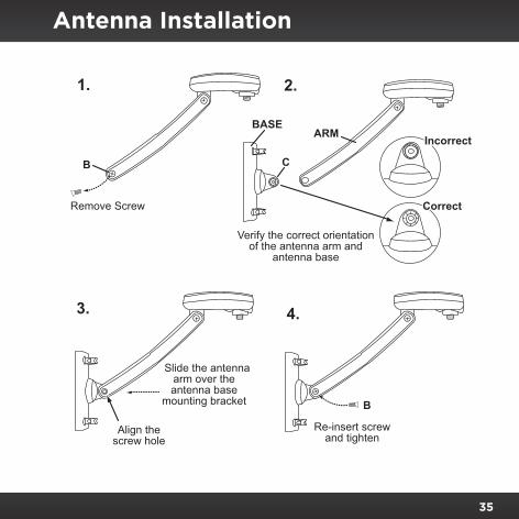
Next, the antenna arm with the pod needs to be attached to the antenna base . Refer to the illustration on page 42 and attach the antenna arm to the antenna base:
1. Use a phillips screwdriver to remove the screw B from the antenna arm .
2. The mounting bracket C on the antenna base has two sides . Before you slide the antenna arm over the mounting bracket C, be sure the antenna arm and antenna base are in the correct orientation as shown .
3. When correctly oriented, slide the antenna arm over the mounting bracket C on the antenna base and align the screw holes in the mounting bracket with the screw hole in the antenna arm .
4. When the screw hole is aligned, re-insert screw B and snug it until it is tight .
35
Antenna Installation
Re-insert screwand tighten
Slide the antennaarm over theantenna base
mounting bracket
Align thescrew hole
CorrectCorrect
Verify the correct orientationof the antenna arm and
antenna base
ARMBASE
C
IncorrectIncorrect
Remove Screw
B
B
1.
3.
2.
4.

36
Antenna Installation
Second: Determining a Location for the Antenna
For correct operation and best reception of the SiriusXM signal, it is important that the Outdoor Home Antenna is located in a place where it will have a clear view of the satellite in the sky . Obstructions such as bushes, trees, other homes or buildings, overhangs, soffits, chimneys, gables, dormers, etc ., will impair or prevent the antenna from receiving a signal .
The best reception is obtained if the pod portion of the antenna (where the logo is printed) has a clear 360 degree view of the sky within the cone-shaped area shown in the following illustration .
If you cannot obtain a clear 360 degree view of the sky in your location, then you’ll need at least a clear view of the south sky . If you look closely at the next illustration, you can see that the antenna does not have a clear view of the sky in all directions due to trees . However, it does have a clear view of the sky toward the south, in the direction of the satellite . Your antenna will also need to have a clear view of the sky in the south direction . Not sure which way is south? Think about where the sun rises (in the east) and sets (in the west) . Then stand so that east is to your left and you’ll be
No obstructions to thesky within this area

37
facing south .
Once you have determined a possible mounting location for your area, it is recommended that you put the antenna in place temporarily and connect the antenna to your Radio as shown in the following illustration . Using the Antenna Aiming or Signal Indicator feature of your Radio, verify that your antenna is receiving a good signal . (Consult the User Guide of the Radio for
Antenna Installation
No obstructions tothe south sky
SOUTH

38
Antenna Installation
specific instructions on how to access the feature .)
Third: Antenna Mounting Options
There are three possible mounting options for the Outdoor Home Antenna, and the antenna mounting location you have chosen may determine which mounting methods you can use:
•Wall Mount: Mounting the antenna directly on the side of a home or building .
•Roof Mount: Mounting the antenna on the soffit of a home or building .
•Mast Mount: Mounting the antenna on a mast or pole, such as an existing satellite TV dish mast, an existing TV antenna mast, or other mast or pole, not exceeding 2 inches in diameter .
Wall Mount
The antenna mounting bracket should be oriented in a vertical position (as shown) and mounted directly to the wall of the building or home using the provided #10 screws .
Remember to avoid blocking the antenna’s view of the sky as described in the previous section by locating the antenna too high under the eaves or
RG-174
RG-6 Adapter Cable
Signal Indicator
SATELLITE
TERRESTRIAL
2 3 4 5 6 7 8 9 0 direct
jump
FM
menu
1
39
Antenna Installation
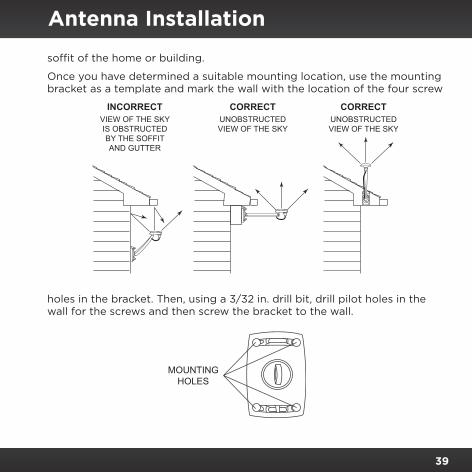
soffit of the home or building .
Once you have determined a suitable mounting location, use the mounting bracket as a template and mark the wall with the location of the four screw
holes in the bracket . Then, using a 3/32 in . drill bit, drill pilot holes in the wall for the screws and then screw the bracket to the wall .
MOUNTINGHOLES
INCORRECTVIEW OF THE SKYIS OBSTRUCTEDBY THE SOFFITAND GUTTER
CORRECTUNOBSTRUCTEDVIEW OF THE SKY
CORRECTUNOBSTRUCTEDVIEW OF THE SKY
40
Antenna Installation
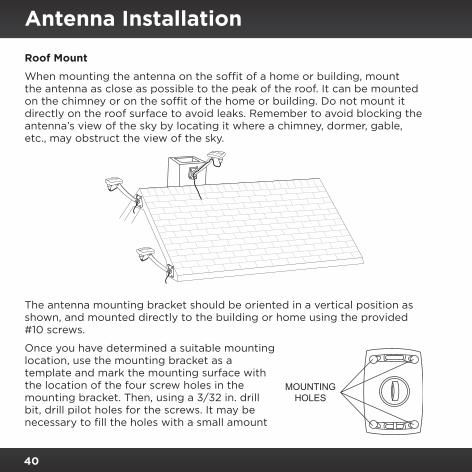
Roof Mount
When mounting the antenna on the soffit of a home or building, mount the antenna as close as possible to the peak of the roof . It can be mounted on the chimney or on the soffit of the home or building . Do not mount it directly on the roof surface to avoid leaks . Remember to avoid blocking the antenna’s view of the sky by locating it where a chimney, dormer, gable, etc ., may obstruct the view of the sky .
The antenna mounting bracket should be oriented in a vertical position as shown, and mounted directly to the building or home using the provided #10 screws .
Once you have determined a suitable mounting location, use the mounting bracket as a template and mark the mounting surface with the location of the four screw holes in the mounting bracket . Then, using a 3/32 in . drill bit, drill pilot holes for the screws . It may be necessary to fill the holes with a small amount
MOUNTINGHOLES

41
Antenna Installation
of roof cement or caulk to insure a watertight installation . Screw the bracket to the mounting surface using the provided #10 screws .
Mast Mount
The Outdoor Home Antenna can be mounted on most any mast or pole which does not exceed 2 inches in diameter using the provided U-bolts and mounting brackets . If you have a satellite TV dish, the Outdoor Home Antenna may be mounted on the same mast as the satellite dish, but remember that the dish cannot obstruct the antenna’s view of the south sky .
To mount the antenna to the mast, you will need to use the two provided U-bolts, the two mounting brackets, and the four hex nuts . Keep in mind that the antenna cable is routed under the lower U-bolt, in the slot provided
42
Antenna Installation
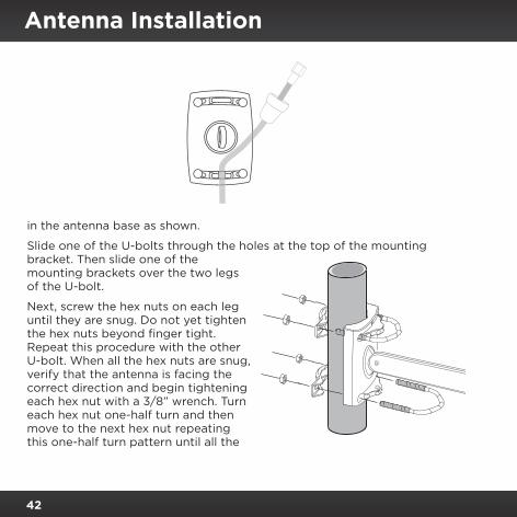
in the antenna base as shown .
Slide one of the U-bolts through the holes at the top of the mounting bracket . Then slide one of the mounting brackets over the two legs of the U-bolt .
Next, screw the hex nuts on each leg until they are snug . Do not yet tighten the hex nuts beyond finger tight . Repeat this procedure with the other U-bolt . When all the hex nuts are snug, verify that the antenna is facing the correct direction and begin tightening each hex nut with a 3/8” wrench . Turn each hex nut one-half turn and then move to the next hex nut repeating this one-half turn pattern until all the

43
Antenna Installation
hex nuts are equally tight . Tighten the hex nuts enough so that the antenna is secured to the mast or pole, but do not overtighten them .
Fourth: Adjusting and Aiming the Antenna
The pod portion of the antenna (where the logo is printed) needs to be adjusted and aimed so that it is level and horizontal to the sky . As shown in the following illustration, there are two possible adjustments that may be made on the antenna to accomplish this: tilting the antenna pod itself (1), and adjusting the antenna support arm (2), as shown .
Slightly loosen the adjustment screws and position the antenna so that the top of the antenna pod is level, with the top of the pod horizontal to the sky
1Antenna Pod
HORIZONTAL LEVEL
SKY
AdjustmentScrew
AdjustmentScrew
2

44
Antenna Installation
as shown . When the antenna is adjusted correctly, tighten the adjustment screws but be careful not to overtighten them .
Your Signal Distribution Kit has been designed and built to be trouble-free, but if you experience a problem, try this:
•Check that all connections are firm and secure .
If This Happens Try this:
Radio displays “Antenna Error” or “Check Antenna” message .
Check the antenna cable connections to be sure they are connected tightly .
Radio displays “No Signal” or “Acquiring Signal” message .
•The Radio is not receiving a good signal . Check that the antenna has a clear view of the sky, and that the antenna has a clear view of the south sky, or in the direction you determined from the map .
•This message may also be an indication that your cable length has exceeded 150 ft ., and that an in-line amplifier is required for your installation .
Troubleshooting

45
Troubleshooting
Product Specifications
Outdoor Home Antenna Radome 3 .5 in x 2 .875 in (90 mm x 75 mm) Arm Length 8 .0 in (203 mm) Weight 1 .75 lbs (794 g) Temperature -40° to +185° F (-40° to +85° C)
Patent and Environmental InformationPatent InformationIt is prohibited to, and you agree that you will not, copy, decompile, disassemble, reverse engineer, hack, manipulate, or otherwise access and/or make available any technology incorporated in this product . Furthermore, the AMBE® voice compression software included in this product is protected by intellectual property rights including patent rights, copyrights, and trade secrets of Digital Voice Systems, Inc . The software is licensed solely for use within this product . The music, talk, news, entertainment, data, and other content on the Services are protected by copyright and other intellectual property laws and all ownership rights remain with the respective content and data service providers . You are prohibited from any export of the content and/or data (or derivative thereof ) except in compliance with applicable export laws, rules and regulations . The user of this or any other software contained in a SiriusXM Radio is explicitly prohibited from attempting to copy, decompile, reverse engineer, hack, manipulate or disassemble the object code, or in any other way convert the object code into human-readable form .
Environmental InformationFollow local guidelines for waste disposal when discarding packaging and electronic appliances .
Your Signal Distribution Kit is packaged with cardboard, polyethylene, etc ., and does not contain any unnecessary materials .

46
The user is cautioned that changes or modifications not expressly approved by Sirius XM Radio Inc . can void the user’s authority to operate this device .
This device complies with Part 15 of the FCC Rules . Operation is subject to the following two conditions:
1 . This device may not cause harmful interference .
2 . This device must accept any interference received, including interference that may cause undesired operation .
This equipment has been tested and found to comply with the limits for a Class B digital device, pursuant to Part 15 of the FCC Rules . These limits are designed to provide reasonable protection against harmful interference in a residential installation .
This equipment generates, uses, and can radiate radio frequency energy and, if not installed and used in accordance with the installation instructions, may cause harmful interference to radio communications . However, there is no guarantee that interference will not occur in a particular installation . If this equipment does cause harmful interference to radio or television reception, which can be determined by turning the equipment off and on, the user is encouraged to try to correct the interference by one or more of the following measures:
• Reorient or relocate the receiving antenna of the affected receiver .• Increase the separation between the SiriusXM equipment and the affected
receiver .• Connect the SiriusXM equipment into an outlet on a circuit different from that to
which the affected receiver is connected .• Consult the dealer or an experienced radio/TV technician for help .
WARNING! The FCC and FAA have not certified Satellite Radio Receiver use in any aircraft (neither portable nor permanent installation) . Therefore, Sirius XM Radio Inc . cannot support this type of application or installation .
FCC Statement

47
© 2014 Sirius XM Radio Inc . “Sirius”, “XM” and all related marks and logos are trademarks of Sirius XM Radio Inc . and its subsidiaries . All other trademarks, service marks and logos are the property of their respective owners . All rights reserved .
IMPORTANT NOTICE: REQUIRED SUBSCRIPTIONHardware and subscription sold separately, and activation fee required . Other fees and taxes may apply . Subscriptions governed by SiriusXM Customer Agreement; see www.siriusxm.com . Prices and programming are subject to change . Service automatically renews into the subscription Package you choose (which may differ from the Package which arrived with the Radio), for additional periods of the same length, and automatically bills at the then current rates, after any complimentary trial or promotional period ends, until you call us at 1-866-635-2349 to cancel . XM U .S . Satellite service available only to those at least 18 years of age in the 48 contiguous USA and DC, while SiriusXM Internet Radio is available throughout our satellite area and also AK, HI and PR .
WARNING: This product contains chemicals known to the State of California to cause cancer and birth defects or other reproductive harm .
Copyrights and Trademarks

Sirius XM Radio Inc.1221 Avenue of the AmericasNew York, NY 10020
1.866.635.2349
siriusxm.com
© 2014 Sirius XM Radio Inc .
SXHDK2 140610a