Embed Size (px)
Citation preview
Sybex CCENT 100-101Chapter 11: VLANs and Inter-VLAN
Routing
Instructor & Todd Lammle
Chapter 11 Objectives• The CCENT Topics Covered in this chapter
include:• LAN Switching Technologies
– Describe how VLANs create logically separate networks and the need for routing between them.
• Explain network segmentation and basic traffic management concepts
– Configure and verify VLANs– Configure and verify trunking on Cisco switches
• DTP• Auto negotiation
• IP Routing Technologies– Configure and verify interVLAN routing (Router on a stick)
• sub interfaces• upstream routing• encapsulation
– Configure SVI interfaces
• Troubleshooting– Troubleshoot and Resolve VLAN problems
• identify that VLANs are configured• port membership correct• IP address configured
– Troubleshoot and Resolve trunking problems on Cisco switches• correct trunk states• correct encapsulation configured• correct vlans allowed
2
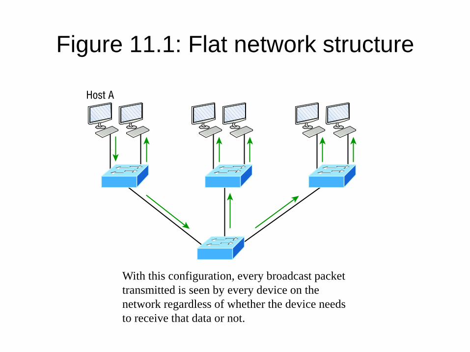
Figure 11.1: Flat network structure
With this configuration, every broadcast packet transmitted is seen by every device on the network regardless of whether the device needs to receive that data or not.
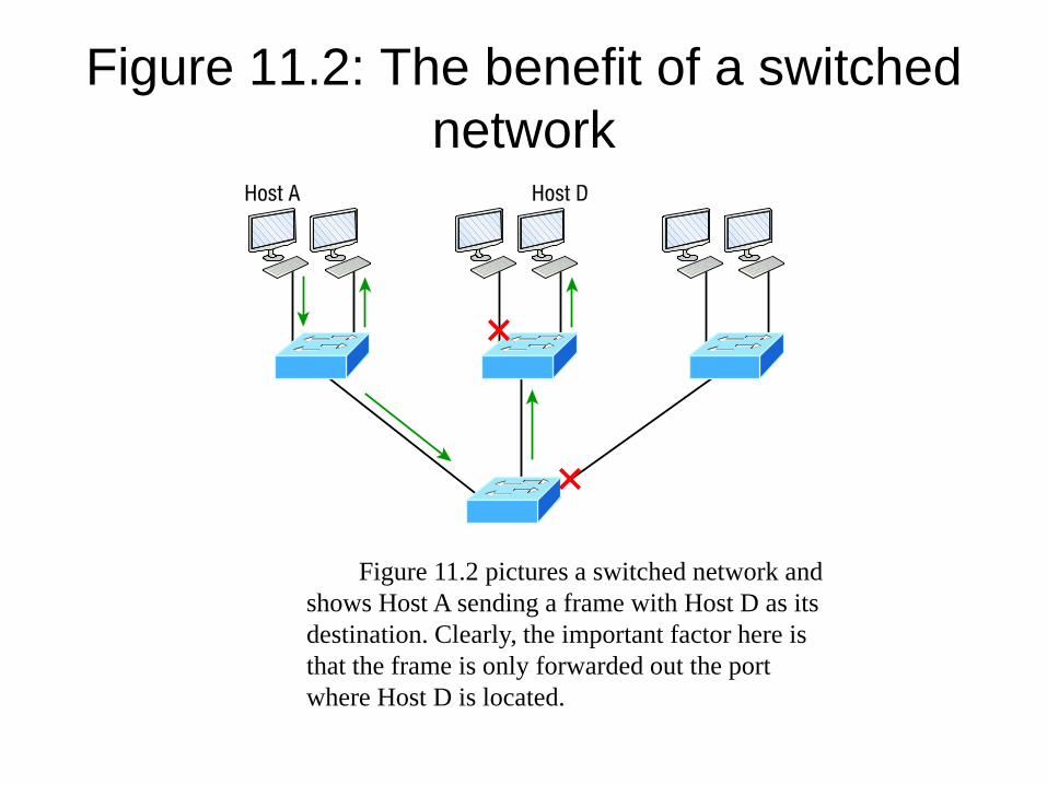
Figure 11.2: The benefit of a switched network
Figure 11.2 pictures a switched network and shows Host A sending a frame with Host D as its destination. Clearly, the important factor here is that the frame is only forwarded out the port where Host D is located.
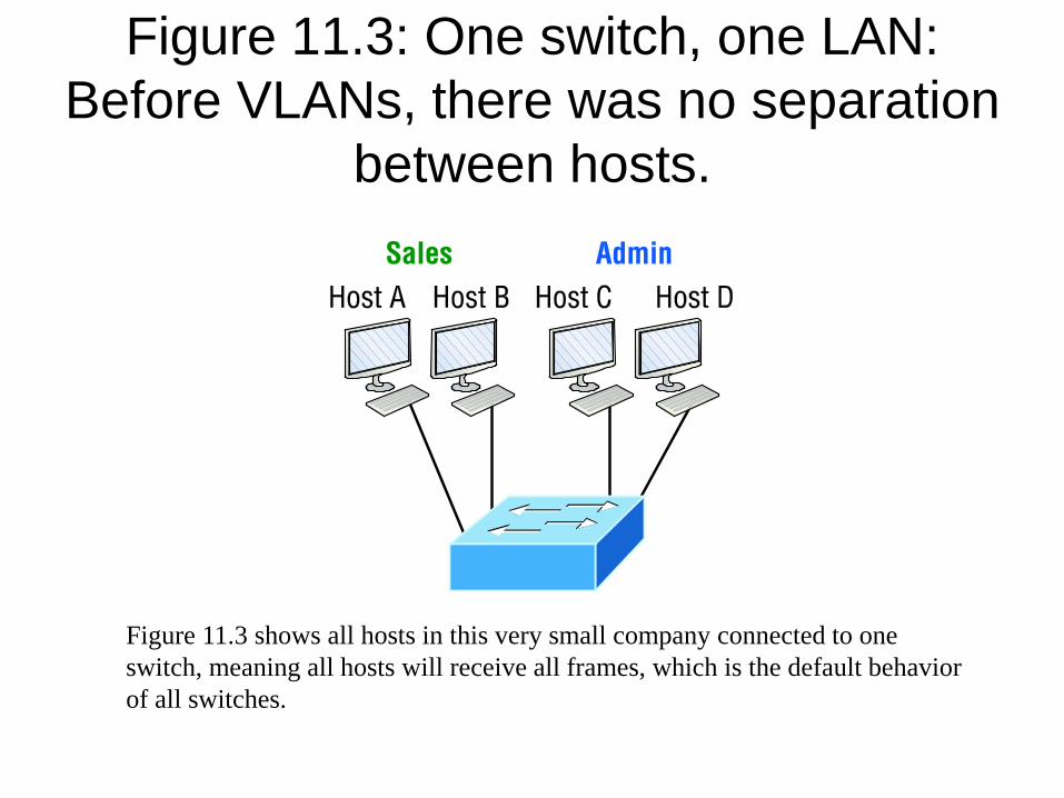
Figure 11.3: One switch, one LAN: Before VLANs, there was no separation
between hosts.
Figure 11.3 shows all hosts in this very small company connected to one switch, meaning all hosts will receive all frames, which is the default behavior of all switches.
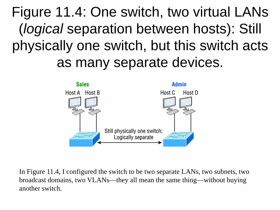
Figure 11.4: One switch, two virtual LANs (logical separation between hosts): Still
physically one switch, but this switch acts as many separate devices.
In Figure 11.4, I configured the switch to be two separate LANs, two subnets, two broadcast domains, two VLANs—they all mean the same thing—without buying another switch.
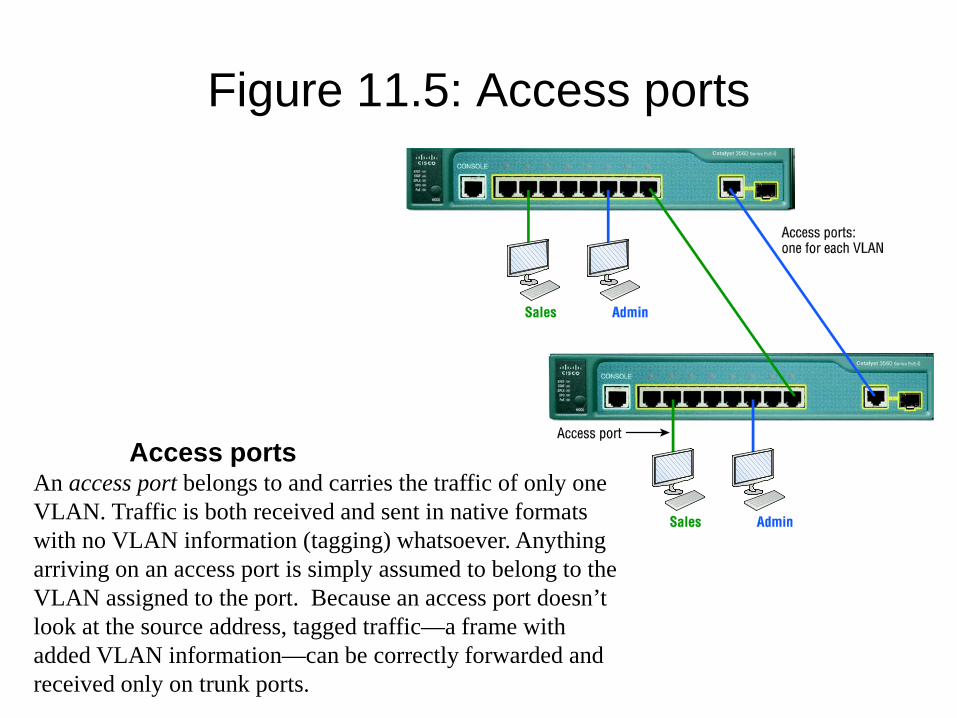
Figure 11.5: Access ports
Access portsAn access port belongs to and carries the traffic of only one VLAN. Traffic is both received and sent in native formats with no VLAN information (tagging) whatsoever. Anything arriving on an access port is simply assumed to belong to the VLAN assigned to the port. Because an access port doesn’t look at the source address, tagged traffic—a frame with added VLAN information—can be correctly forwarded and received only on trunk ports.
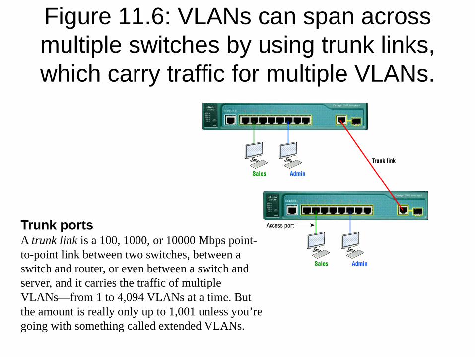
Figure 11.6: VLANs can span across multiple switches by using trunk links, which carry traffic for multiple VLANs.
Trunk portsA trunk link is a 100, 1000, or 10000 Mbps point-to-point link between two switches, between a switch and router, or even between a switch and server, and it carries the traffic of multiple VLANs—from 1 to 4,094 VLANs at a time. But the amount is really only up to 1,001 unless you’re going with something called extended VLANs.
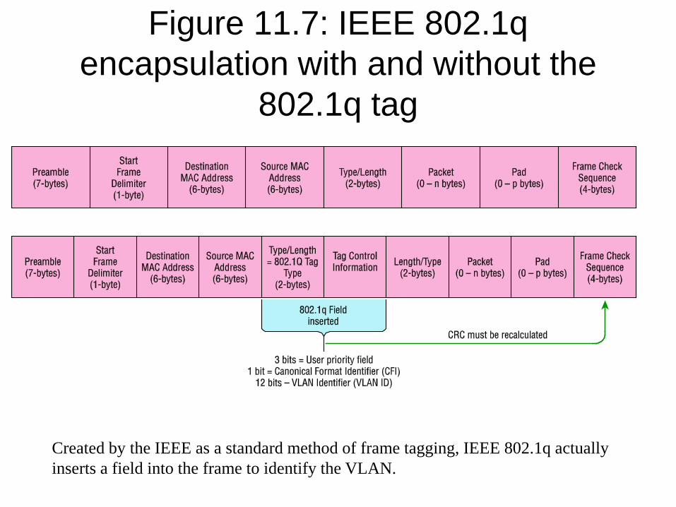
Figure 11.7: IEEE 802.1q encapsulation with and without the
802.1q tag
Created by the IEEE as a standard method of frame tagging, IEEE 802.1q actually inserts a field into the frame to identify the VLAN.
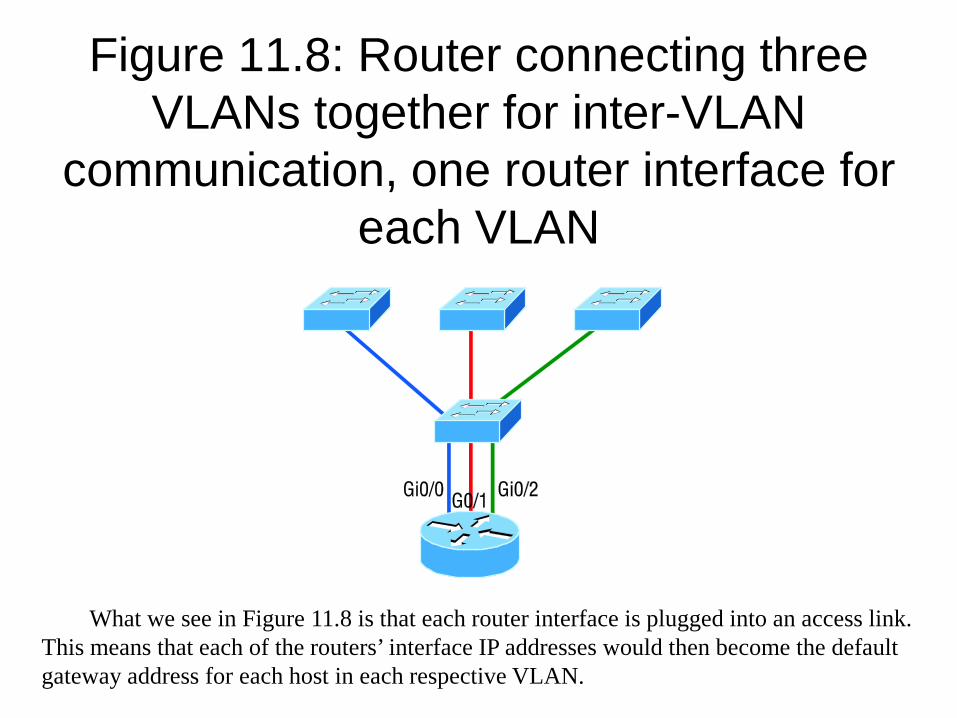
Figure 11.8: Router connecting three VLANs together for inter-VLAN
communication, one router interface for each VLAN
What we see in Figure 11.8 is that each router interface is plugged into an access link. This means that each of the routers’ interface IP addresses would then become the default gateway address for each host in each respective VLAN.
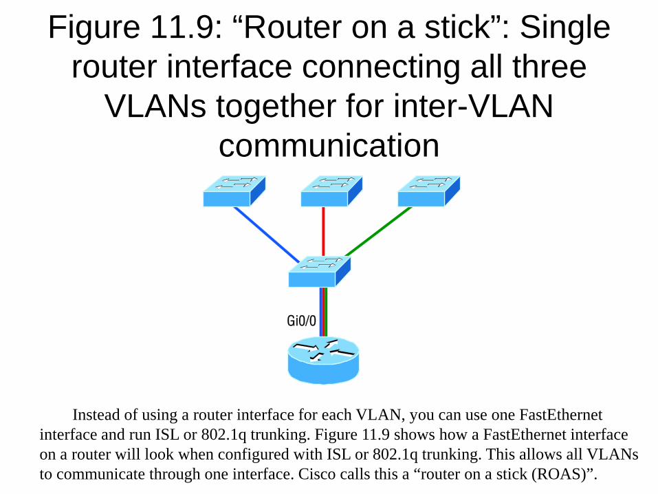
Figure 11.9: “Router on a stick”: Single router interface connecting all three
VLANs together for inter-VLAN communication
Instead of using a router interface for each VLAN, you can use one FastEthernet interface and run ISL or 802.1q trunking. Figure 11.9 shows how a FastEthernet interface on a router will look when configured with ISL or 802.1q trunking. This allows all VLANs to communicate through one interface. Cisco calls this a “router on a stick (ROAS)”.
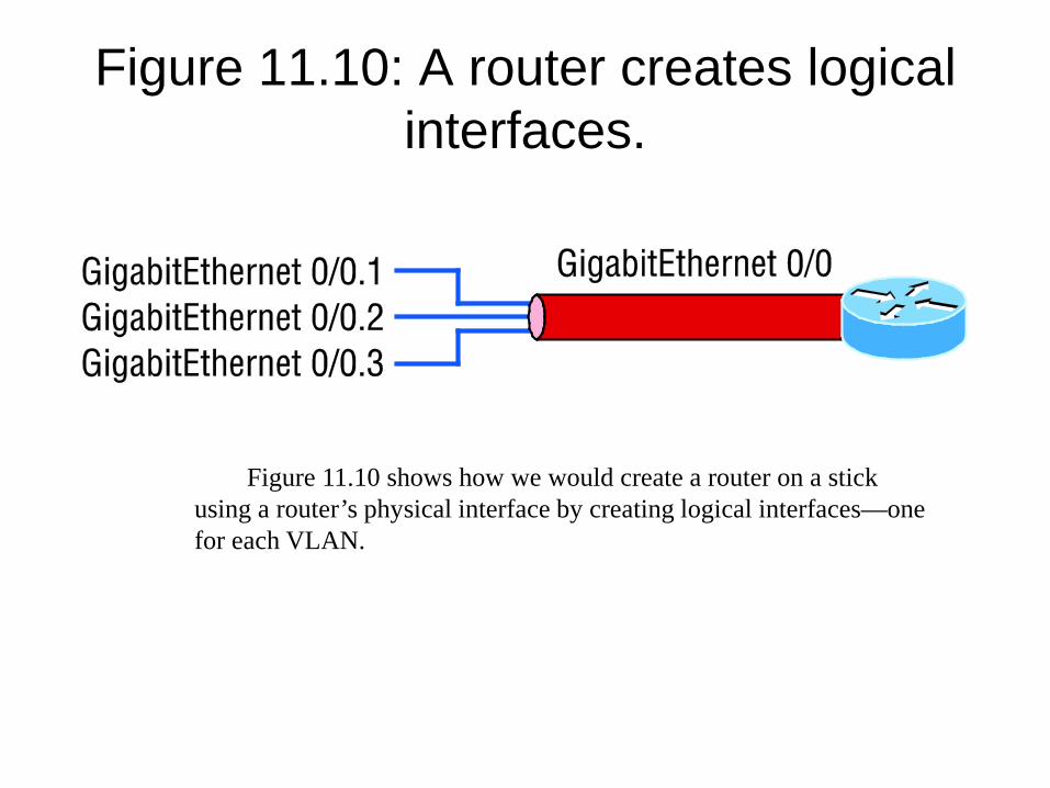
Figure 11.10: A router creates logical interfaces.
Figure 11.10 shows how we would create a router on a stick using a router’s physical interface by creating logical interfaces—one for each VLAN.
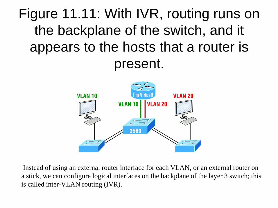
Figure 11.11: With IVR, routing runs on the backplane of the switch, and it
appears to the hosts that a router is present.
Instead of using an external router interface for each VLAN, or an external router on a stick, we can configure logical interfaces on the backplane of the layer 3 switch; this is called inter-VLAN routing (IVR).
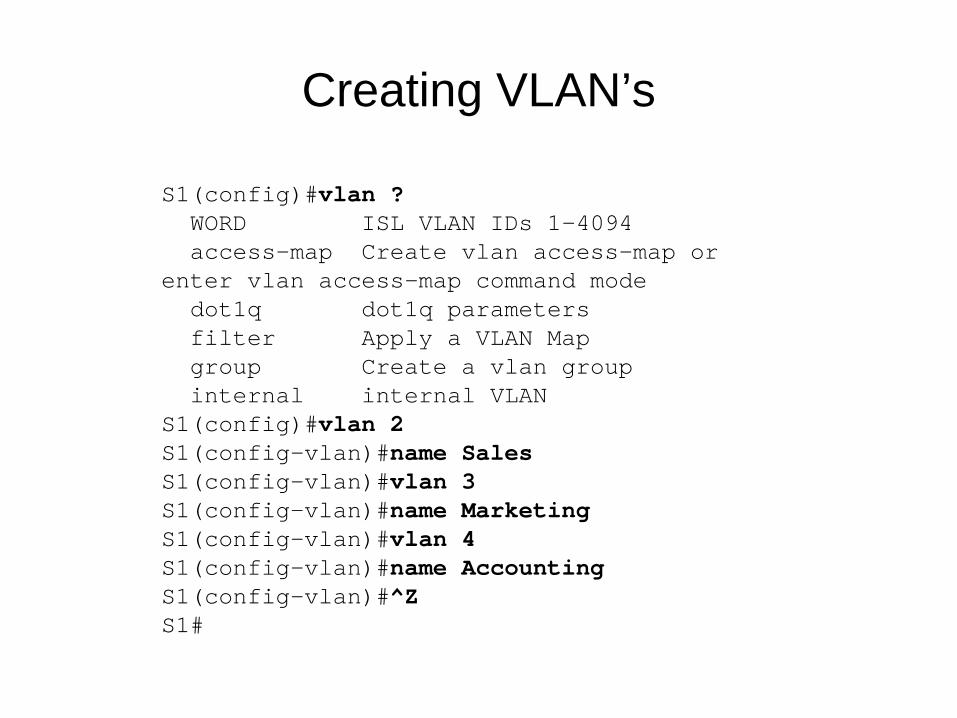
Creating VLAN’s
S1(config)#vlan ?WORD ISL VLAN IDs 1-4094access-map Create vlan access-map or
enter vlan access-map command modedot1q dot1q parametersfilter Apply a VLAN Mapgroup Create a vlan groupinternal internal VLAN
S1(config)#vlan 2S1(config-vlan)#name SalesS1(config-vlan)#vlan 3S1(config-vlan)#name MarketingS1(config-vlan)#vlan 4S1(config-vlan)#name AccountingS1(config-vlan)#^ZS1#
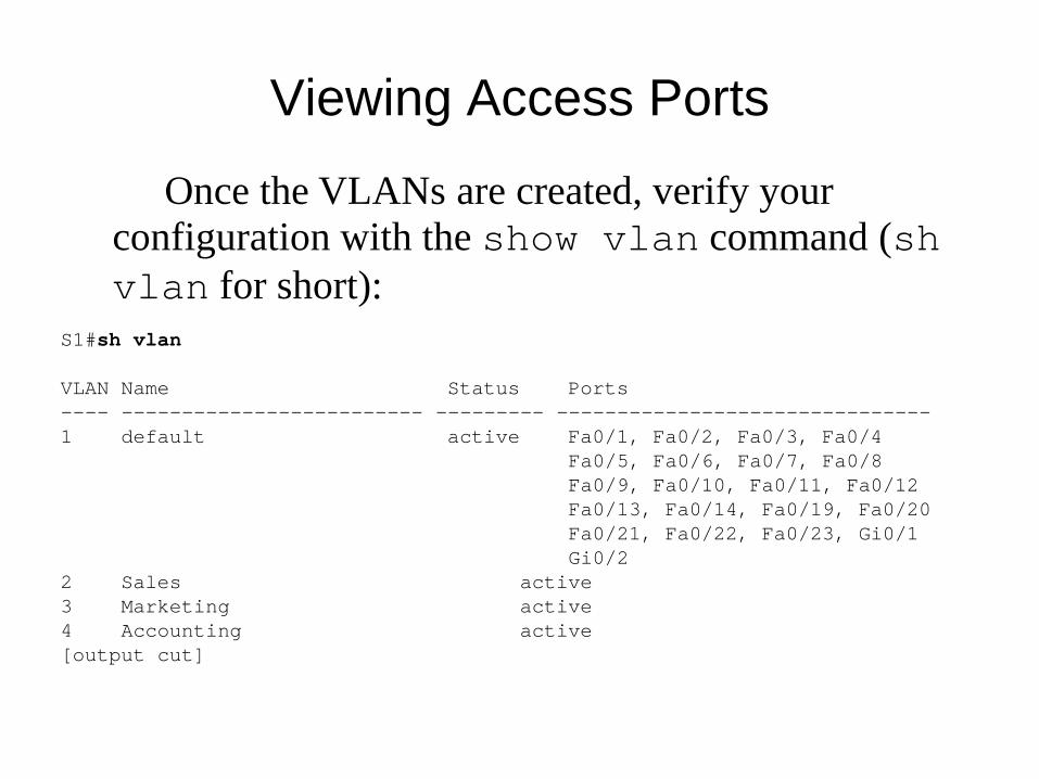
Viewing Access Ports
Once the VLANs are created, verify your configuration with the show vlan command (shvlan for short):
S1#sh vlan
VLAN Name Status Ports---- ------------------------- --------- -------------------------------1 default active Fa0/1, Fa0/2, Fa0/3, Fa0/4
Fa0/5, Fa0/6, Fa0/7, Fa0/8Fa0/9, Fa0/10, Fa0/11, Fa0/12Fa0/13, Fa0/14, Fa0/19, Fa0/20Fa0/21, Fa0/22, Fa0/23, Gi0/1Gi0/2
2 Sales active3 Marketing active4 Accounting active[output cut]

Configuring Trunk ports
The following switch output shows the trunk configuration on interfaces Fa0/15–18 as set to trunk:
S1(config)#int range f0/15-18S1(config-if-range)#switchport trunk encapsulation dot1qS1(config-if-range)#switchport mode trunk
If you have a switch that only runs the 802.1q encapsulation method, then you wouldn’t use the encapsulation command as I did in the preceding output.
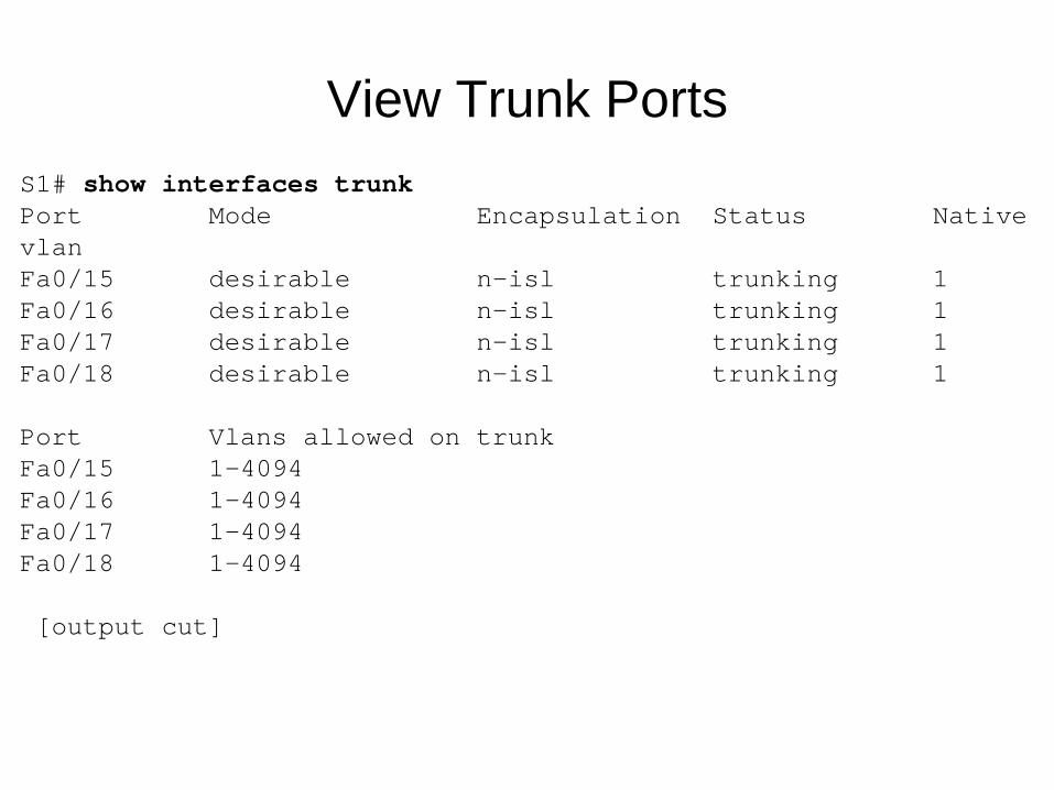
View Trunk PortsS1# show interfaces trunkPort Mode Encapsulation Status Native vlanFa0/15 desirable n-isl trunking 1Fa0/16 desirable n-isl trunking 1Fa0/17 desirable n-isl trunking 1Fa0/18 desirable n-isl trunking 1
Port Vlans allowed on trunkFa0/15 1-4094Fa0/16 1-4094Fa0/17 1-4094Fa0/18 1-4094
[output cut]
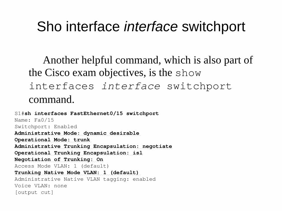
Sho interface interface switchport
Another helpful command, which is also part of the Cisco exam objectives, is the show interfaces interface switchportcommand.
S1#sh interfaces FastEthernet0/15 switchportName: Fa0/15Switchport: EnabledAdministrative Mode: dynamic desirableOperational Mode: trunkAdministrative Trunking Encapsulation: negotiateOperational Trunking Encapsulation: islNegotiation of Trunking: OnAccess Mode VLAN: 1 (default)Trunking Native Mode VLAN: 1 (default)Administrative Native VLAN tagging: enabledVoice VLAN: none[output cut]
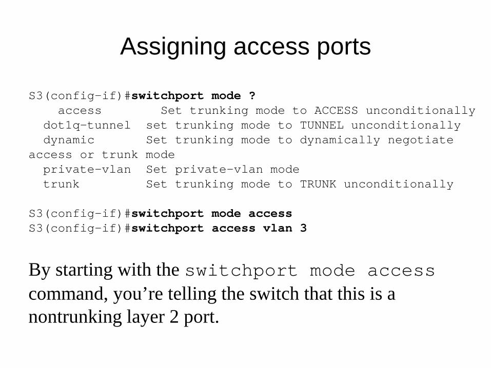
Assigning access ports
S3(config-if)#switchport mode ?access Set trunking mode to ACCESS unconditionally
dot1q-tunnel set trunking mode to TUNNEL unconditionallydynamic Set trunking mode to dynamically negotiate
access or trunk modeprivate-vlan Set private-vlan modetrunk Set trunking mode to TRUNK unconditionally
S3(config-if)#switchport mode accessS3(config-if)#switchport access vlan 3
By starting with the switchport mode accesscommand, you’re telling the switch that this is a nontrunking layer 2 port.
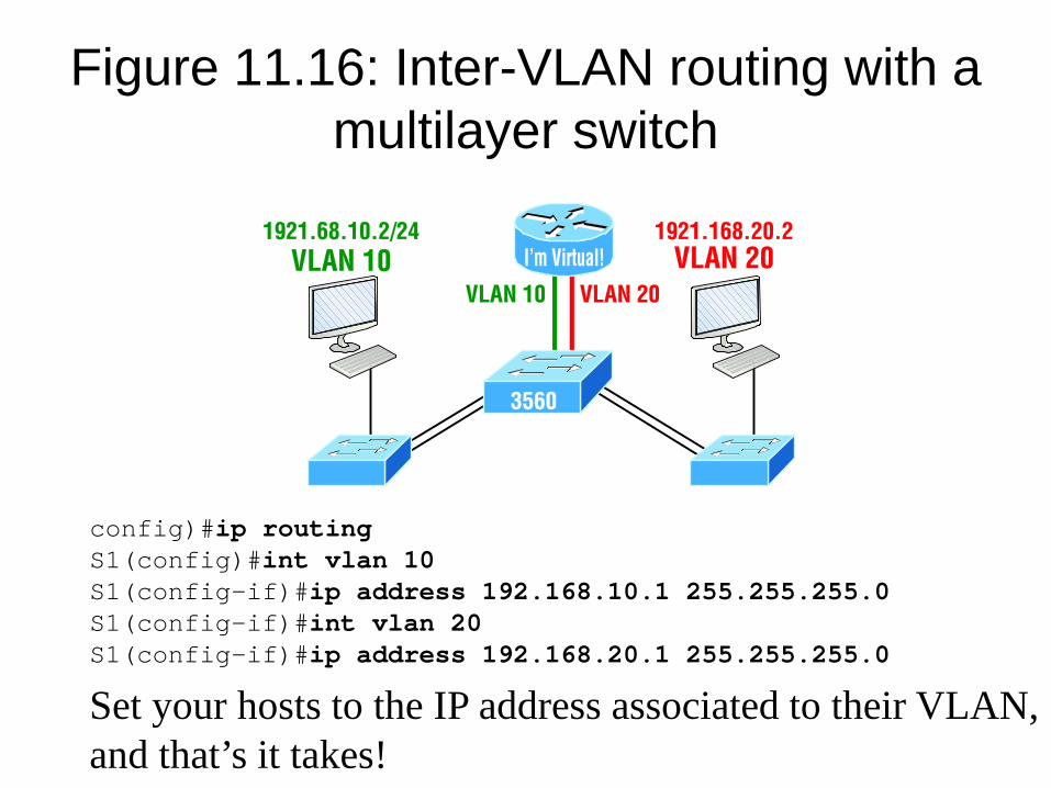
Figure 11.16: Inter-VLAN routing with a multilayer switch
config)#ip routingS1(config)#int vlan 10S1(config-if)#ip address 192.168.10.1 255.255.255.0S1(config-if)#int vlan 20S1(config-if)#ip address 192.168.20.1 255.255.255.0
Set your hosts to the IP address associated to their VLAN, and that’s it takes!
Written Labs and Review Questions
– Read through the Exam Essentials section together in class
– Open your books and go through all the written labs and the review questions.
– Review the answers in class.
21