Embed Size (px)
Citation preview
1
Modern Physics Course Ph-207 Textbook: - Concepts of modern Physics, Sixth Edition-Arthur Beiser
Lecturer name: Dr. Maytham Al-Shanawa
Syllabus CHAPTER 1
RELATIVITY I 1.1 Special Relativity
1.2 The Principle of Relativity
1.2.1 Galilean Transformation of Coordinates
1.2.2 The Speed of Light
1.3 The Michelson Experiment
1.4 Postulates of Special Relativity
1.5 Consequences of Special Relativity
1.5.1 Simultaneity and the Relativity of Time
1.5.2 Time Dilation and Length Contraction
1.6 The Lorentz Transformation
CHAPTER 2
RELATIVITY II 2.1 Relativistic Momentum
2.2 Relativistic Form of Newton’s Laws
2.3 Relativistic Energy
2.4 Mass as a Measure of Energy
2.5 Conservation of Relativistic Momentum and Energy
2.6 General Relativity
CHAPTER 3
The Electrical, Optical Properties and band Theory 3.1 Determination of Electronic Charge
3.2 Millikan Method of Drop Model
3.3 The Free Electron Theory
3.4 Expression for Electrical Conductivity
2
3.5 Expression for Thermal Conductivity
3.6 Electron Microscope
3.7 Optical properties
3.8 Energy Band
CHAPTER 4
Positive Ray and Particle Properties of Waves
4.1 Properties of Positive Rays
4.2 Action of Positive Rays
4.3 Action of Electric Field and Magnetic Field
4.4 Light as an Electromagnetic Wave
4.5 Blackbody Radiation
4.5.1 Enter Planck
4.5.2 The Quantum of Energy
CHAPTER 5
Structure of the Atom
5.1 The Atomic Nature of Matter
5.2 Theory of ∝-Particle Scatters
5.3 The Composition of Atoms
5.4 Rutherford Scattering Formula
5.5 Experimental Verification of Rutherford Scattering Theory
CHAPTER 6
Introduction of Nuclear
6.1 Introduction
6.2 Classification of Nuclear
6.3 General Properties of Nuclear
6.4 Binding Energy
6.5 Nuclear Stability
6.6 Theories of Nuclear Composition
6.7 Nuclear Forces
First Exam 14/11/2016 & Second Exam 19/12/2016
3
CHAPTER 1
RELATIVITY I At the end of the 19th century, scientists believed that they had learned most of
what there was to know about physics. Newton’s laws of motion and his
universal theory of gravitation, Maxwell’s theoretical work in unifying
electricity and magnetism, and the laws of thermodynamics and kinetic theory
employed mathematical methods that successfully explain a wide variety of
phenomena.
However, at the turn of the 20th century, a major revolution shook the world of
physics. In 1900, Planck provided the basic ideas that led to the quantum theory,
and in 1905, Einstein formulated his special theory of relativity.
1.1 Special Relativity
Light waves and other forms of electromagnetic radiation travel through free
space at the speed C = 3.00 * 108 m/s. The speed of light sets an upper limit for
the speeds of particles, waves, and the transmission of information.
Most of our everyday experiences deal with objects that move at speeds much
less than that of light. Newtonian mechanics and early ideas on space and time
were formulated to describe the motion of such objects, and this formalism is
very successful in describing a wide range of phenomena. Although Newtonian
mechanics works very well at low speeds, it fails when applied to particles
whose speeds approach that of light.
In 1905, at the age of 26, Albert Einstein published his special theory of
relativity. Regarding the theory, Einstein wrote. The relativity theory arose from
necessity, from serious and deep contradictions in the old theory from which
there seemed no escape. The strength of the new theory lies in the consistency
and simplicity with which it solves all these difficulties, using only a few very
4
convincing assumptions. Although Einstein made many important contributions
to science, the theory of relativity alone represents one of the greatest
intellectual achievements of the 20th century. With this theory, one can
correctly predict experimental observations over the range of speeds from rest
to speeds approaching the speed of light. Newtonian mechanics, which was
accepted for over 200 years, is in fact a limiting case of Einstein’s special
theory of relativity.
The relativity deals with the analysis of physical events from coordinate
systems moving with constant speed in straight lines with respect to one
another. Also describes physical events from coordinate systems undergoing
general or accelerated motion with respect to each other.
In general, the special theory of relativity follows from two basic postulates:
1. The laws of physics are the same in all reference systems that move
uniformly with respect to one another. That is, basic laws such as F=dp/dt
have the same mathematical form for all observers moving at constant
velocity with respect to one another.
2. The speed of light in vacuum always measured to be 3*108 m/s, and the
measured value is independent of the motion of the observer or of the
motion of the source of light. That is, the speed of light is the same for all
observers moving at constant velocities.
1.2 The Principle of Relativity
In order to describe a physical event, it is necessary to establish a frame of
reference, such as one that is fixed in the laboratory.
According to the principle of Newtonian relativity, the laws of mechanics must
be the same in all inertial frames of reference. For example, if you perform an
experiment while at rest in a laboratory, and an observer in a passing truck
moving with constant velocity performs the same experiment, Newton’s laws
5
may be applied to both sets of observations. Specifically, in the laboratory or in
the truck a ball thrown up rises and returns to the thrower’s hand. Moreover,
both events are measured to take the same time in the truck or in the laboratory,
and Newton’s second law may be used in both frames to compute this time.
Although these experiments look different to different observers and the
observers measure different values of position and velocity for the ball at the
same times, both observers agree on the validity of Newton’s laws and
principles such as conservation of energy and conservation of momentum. The
only thing that can be detected is the relative motion of one frame with respect
to the other. That is, the notion of absolute motion through space is
meaningless, as is the notion of a single, preferred reference frame. Indeed, one
of the firm philosophical principles of modern science is that all observers are
equivalent and that the laws of nature must take the same mathematical form for
all observers. Laws of physics that exhibit the same mathematical form for
observers with different motions at different locations are said to be covariant.
In order to show the underlying equivalence of measurements made in different
reference frames and hence the equivalence of different frames for doing
physics, we need a mathematical formula that systematically related
measurements made in one reference frame to those in another. Such a relation
is called a transformation, and the one satisfying Newtonian relativity is the so
called Galilean transformation, which owes its origin to Galileo. It can be
derived as follows.
1.2.1 Galilean Transformation of Coordinates
Consider two inertial systems or frames S and S/. The frame S/ moves with a
constant velocity v along the xx/ axes, where v is measured relative to the frame
S. Clocks in S and S/ are synchronized, and the origins of S and S/ coincide at t=
t/ = 0. We assume that a point event, a physical phenomenon such as a light bulb
flash, occurs at the point P.
6
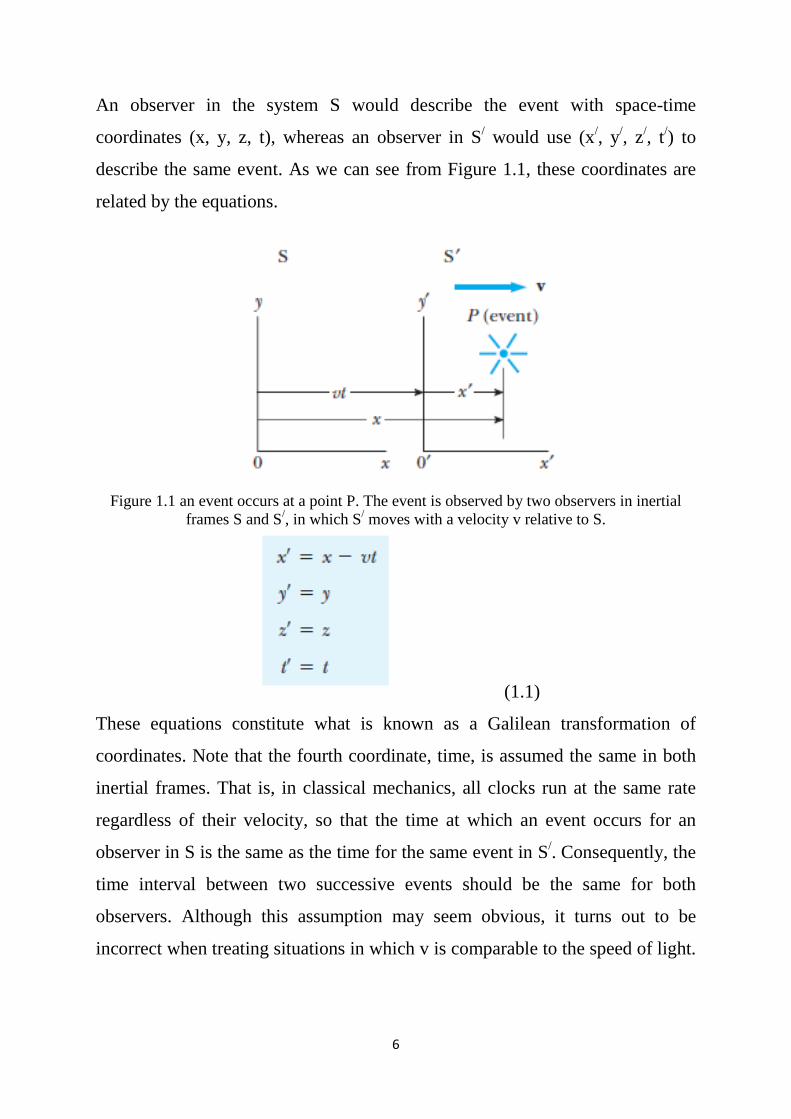
An observer in the system S would describe the event with space-time
coordinates (x, y, z, t), whereas an observer in S/ would use (x/, y/, z/, t/) to
describe the same event. As we can see from Figure 1.1, these coordinates are
related by the equations.
Figure 1.1 an event occurs at a point P. The event is observed by two observers in inertial
frames S and S/, in which S/ moves with a velocity v relative to S.
(1.1)
These equations constitute what is known as a Galilean transformation of
coordinates. Note that the fourth coordinate, time, is assumed the same in both
inertial frames. That is, in classical mechanics, all clocks run at the same rate
regardless of their velocity, so that the time at which an event occurs for an
observer in S is the same as the time for the same event in S/. Consequently, the
time interval between two successive events should be the same for both
observers. Although this assumption may seem obvious, it turns out to be
incorrect when treating situations in which v is comparable to the speed of light.
7
In fact, this point represents one of the most profound differences between
Newtonian concepts and the ideas contained in Einstein’s theory of relativity.
An immediate and important consequence of the invariance of the distance
between two points under the Galilean transformation is the invariance of force.
For example if 𝐹𝐹 = 𝑘𝑘𝑘𝑘𝑘𝑘(𝑥𝑥2 −𝑥𝑥1)2 gives the electric force between two charges q, Q
located at x1 and x2 on the x-axis in frame S, F/, the force measured in S/, is
given by 𝐹𝐹/ = 𝑘𝑘𝑘𝑘𝑘𝑘
(𝑥𝑥2/−𝑥𝑥1
/)2 = F since, x/
2 – x/1 = x2 - x1. In fact, any force would be
invariant under the Galilean transformation as long as it involved only the
relative positions of interacting particles. Now suppose two events are separated
by a distance dx and a time interval dt as measured by an observer in S. It
follows from Equation 1.1 that the corresponding displacement dx/ measured by
an observer in S/ is given by dx/= dx - vdt, where dx is the displacement
measured by an observer in S. Because dt = dt/, we find that;
where 𝑢𝑢𝑥𝑥 and 𝑢𝑢𝑥𝑥/ are the instantaneous velocities of the object relative to S and
𝑆𝑆/, respectively. The result that called the Galilean addition law for velocities
(or Galilean velocity transformation), are used in everyday observations and is
consistent with our intuitive notions of time and space. To obtain the relation
between the accelerations measured by observers in S and𝑆𝑆/, we take a
derivative of Equation 1.2 with respect to time and use the results that dt= dt/
and 𝑣𝑣 is constant:
8
Thus, observers in different inertial frames measure the same acceleration for an
accelerating object. The mathematical terminology is to say that lengths (∆𝑋𝑋),
time intervals, and accelerations are invariant under a Galilean transformation.
Transformation equations, in addition to converting measurements made in one
inertial frame to those in another, may be used to show the variance of physical
laws.
Exercise1: Assume that Newton’s law Fx= max has been shown to hold by an
observer in an inertial frame S. Show that Newton’s law also holds for an
observer in S/ or is covariant under the Galilean transformation, that is, has the
form 𝐹𝐹𝑋𝑋/ = 𝑚𝑚/𝑎𝑎𝑋𝑋
/ . Note that inertial mass is an invariant quantity in Newtonian
dynamics.
Exercise2: conservation of linear momentum is covariant under the Galilean
transformation. Assume that two masses 𝑚𝑚1/ and 𝑚𝑚2
/ are moving in the positive
x direction with velocities 𝑣𝑣1/ and 𝑣𝑣2
/ as measured by an observer in 𝑆𝑆/before a
collision. After the collision, the two masses stick together and move with a
velocity 𝑣𝑣/ in𝑆𝑆/. Show that if an observer in 𝑆𝑆/ finds momentum to be
conserved, so does an observer in S.
1.2.2 The Speed of Light
The speed of light was C only with respect to the ether or a frame fixed in the
ether called the ether frame, where C;
𝐶𝐶 = (𝑢𝑢𝑜𝑜 𝜀𝜀𝑜𝑜)−1/2 =3*108 m/s
Permeability of vacuum μo =12.566 e-7 (kg.m.s-2.A-2)
Permittivity of vacuum εo =8.854 e-12 (kg-1.m-3.s4.A2)
In any other frame moving at speed 𝑣𝑣 relative to the ether frame, the Galilean
addition law expected to hold. Thus, the speed of light in this other frame was
expected to be c – 𝑣𝑣 for light travelling in the same direction as the frame, c + 𝑣𝑣
for light travelling opposite to the frame, and in between these two values for
9
light moving in an arbitrary direction with respect to the moving frame. Because
the existence of the ether and a preferred ether frame would show that light was
similar to other classical waves (in requiring a medium). Scientists realizing that
the Earth moved rapidly around the Sun at 30 km/s, they decided to use the
Earth itself as the moving frame in an attempt to improve their are a small
changes in light velocity.
From our point of view of observers fixed on Earth, we may say that we are
stationary and that the special ether frame moves past us with speed𝑣𝑣.
Determining the speed of light under these circumstances is just like
determining the speed of an aircraft in a moving air current or wind, and
consequently we speak of an “ether wind” blowing through our apparatus fixed
to the Earth.
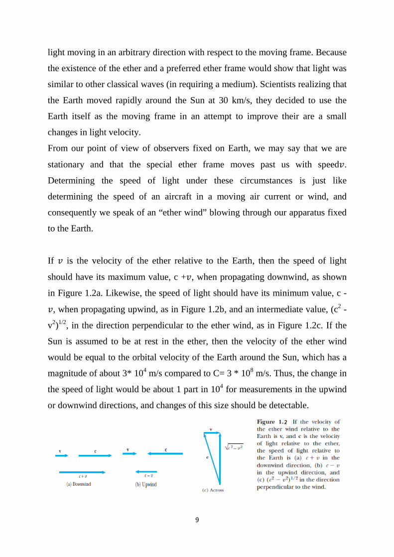
If 𝑣𝑣 is the velocity of the ether relative to the Earth, then the speed of light
should have its maximum value, c +𝑣𝑣, when propagating downwind, as shown
in Figure 1.2a. Likewise, the speed of light should have its minimum value, c -
𝑣𝑣, when propagating upwind, as in Figure 1.2b, and an intermediate value, (c2 -
v2)1/2, in the direction perpendicular to the ether wind, as in Figure 1.2c. If the
Sun is assumed to be at rest in the ether, then the velocity of the ether wind
would be equal to the orbital velocity of the Earth around the Sun, which has a
magnitude of about 3* 104 m/s compared to C= 3 * 108 m/s. Thus, the change in
the speed of light would be about 1 part in 104 for measurements in the upwind
or downwind directions, and changes of this size should be detectable.
10
1.3 The Michelson Experiment
American physicist Albert A. Michelson and Edward W. Morley performed the
famous experiment designed to detect small changes in the speed of light with
motion of an observer through the ether in 1887.
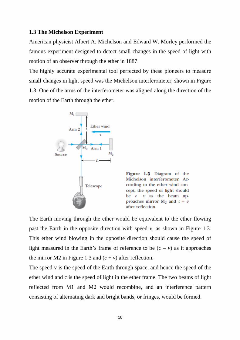
The highly accurate experimental tool perfected by these pioneers to measure
small changes in light speed was the Michelson interferometer, shown in Figure
1.3. One of the arms of the interferometer was aligned along the direction of the
motion of the Earth through the ether.
The Earth moving through the ether would be equivalent to the ether flowing
past the Earth in the opposite direction with speed v, as shown in Figure 1.3.
This ether wind blowing in the opposite direction should cause the speed of
light measured in the Earth’s frame of reference to be (c – v) as it approaches
the mirror M2 in Figure 1.3 and (c + v) after reflection.
The speed v is the speed of the Earth through space, and hence the speed of the
ether wind and c is the speed of light in the ether frame. The two beams of light
reflected from M1 and M2 would recombine, and an interference pattern
consisting of alternating dark and bright bands, or fringes, would be formed.
11
During the experiment, the interference pattern was observed while the
interferometer was rotated through an angle of 90°. This rotation would change
the speed of the ether wind along the direction of the arms of the interferometer.
The effect of this rotation should have been to cause the fringe pattern to shift
slightly but measurably. Measurements failed to show any change in the
interference pattern! Other researchers under various conditions repeated the
Michelson–Morley experiment and at different times of the year when the ether
wind was expected to have changed direction and magnitude, but the results
were always the same: No fringe shift of the magnitude required was ever
observed!
The negative results of the Michelson experiment not only meant that the
speed of light does not depend on the direction of light propagation but
also contradicted the ether hypothesis.
The negative results also meant that it was impossible to measure the
absolute velocity of the Earth with respect to the ether frame.
Example: - Two boats move from the same point A, first one (1) pass across
the river to the opposite coast and return back to same point A, the second boat
(2) moves in same direction of river current and return back to point A.
Which boat need more time to return to the starting point?
Assume the speed of river current𝑣𝑣 , the river width d.
Answer:-
• For the first boat in order to return to the starting point A, it must move
against the river current direction with speed V.
𝑉𝑉2 = 𝑉𝑉′2 + 𝑣𝑣2 , 𝑉𝑉/2 = 𝑉𝑉2 − 𝑣𝑣2, 𝑉𝑉′ = 𝑉𝑉 �1 − 𝑣𝑣2
𝑉𝑉2
In general S = d / t
12
T1= 2𝑑𝑑 / 𝑉𝑉′= 2𝑑𝑑
𝑉𝑉 �1−𝑣𝑣2
𝑉𝑉2
total period for first boat travel (departure and
return back).
• The second boat, the period of departure 𝑑𝑑
(𝑉𝑉+𝑣𝑣), why
the period of return𝑑𝑑
(𝑉𝑉−𝑣𝑣), why
T2 = 𝑑𝑑
(𝑉𝑉+𝑣𝑣) + 𝑑𝑑
(𝑉𝑉−𝑣𝑣), T2 =
2𝑑𝑑
𝑉𝑉(1−𝑣𝑣2
𝑉𝑉2 )
So: T1 > T2
1.4 Postulates of Special Relativity
In the previous section, we noted the impossibility of measuring the speed of the
ether with respect to the Earth and the failure of the Galilean velocity
transformation in the case of light.
Albert Einstein proposed a theory that boldly removed these difficulties and at
the same time completely altered our notion of space and time. Einstein based
his special theory of relativity on two postulates.
The Principle of Relativity: All the laws of physics have the same form
in all inertial reference frames.
The Constancy of the Speed of Light: The speed of light in vacuum has
the same value, c = 3 * 108 m/s, in all inertial frames, regardless of the
velocity of the observer or the velocity of the source emitting the light.
13
1.5 Consequences of Special Relativity
As mentioned before in old wave theory that considered the ether is the constant
universal frame of reference, the speed of light is C= 3*108 m/s. So almost the
moving must be fallow the Particular reference, maybe (way, earth surface, Sun
or any other centre). However, must be selecting the suitable reference frame
for each case. If the ether is widespread in all the space, then will we can
attribute all the movements to the ether. The absence of ether means that there is
no special universal reference frame, for that all the movement belong the
observer.
Relativity: - describing and analysis of the physical phenomena are arising
from the absence of a distinct universal reference frame.
Summarise;-
Special theory of relativity: - it is dealing with problems including inertial
frames of reference moving uniformly for each other’s.
General theory of relativity: -it is dealing with problems including accelerate
frames of reference for are others.
Galilean Transformation and Newton’s Laws:-
1- Inertial Law; for particle moving uniformly (Ux) respect for S system, the
movement obey the first law of Newton. The XYZ is inertial coordinate,
the speed of particle for observer in S/ system is.
Ux/ = Ux – v
2- Force or Accelerate Law, mass is absolute value and independent of
observer position and the movement,
m = m/, a = a/
then
F = ma
14
F = F/ = ma = m/a/
3- Action and Reaction Law, the interaction between two particles A, B in S
system can describe it in third law
FAB = -FBA
As mentioned in Galilean transformation (force is absolute quantity)
F/ = F
F/AB = -F/
BA
Example:-
Two riders passed in front of fixe observer; first rider moving uniformly with
speed 20km/h, second rider moving also uniformly in speed 10Km/h, find
1- The position of riders for observer at passing point after 0.1h.
2- The position of first rider to respect of second rider after 0.3h from
passing point.
Answer;
1-
x1 = xo + v1t
x1 = 0 + 20 * 0.1 = 2Km
x2 = xo + v2t = 0 + 10 * 0.1 = 1Km
2-
A basic premise of Newtonian mechanics is that a universal time scale exists
that is the same for all observers. In fact, Newton wrote that “Absolute, true and
mathematical time, of itself, and from its own nature, flows equably without
relation to anything external. Thus, Newton and his followers simply took
simultaneity for granted. In his special theory of relativity, Einstein abandoned
this assumption. According to Einstein, a time interval measurement
depends on the reference frame in which the
measurement that made.
15
Two events that are simultaneous in one frame are in general not simultaneous
in a second frame moving with respect to the first. That is, simultaneity is not an
absolute concept, but one that depends on the state of motion of the observer.
Exercise;
Prove the liner momentum and kinetin energy are conservative at inertial frame
S and motional inertial frame S/ for two masses suffering from elastic collusion,
assume the masses are m1, m2 and their peed before and after collusion are u1, u2
also U1, U2 respectively for S. Write done the equations’ form at S/ frame.
1.6 The Lorentz Transformation
We have seen that the Galilean transformation is not valid when v approaches
the speed of light, so that we need derive the correct coordinate and velocity
transformation equations that apply for all speeds in the range of (0≤v≥ c). The
Lorentz coordinate transformation is a set of formulas that relates the space and
time coordinates of two inertial observers moving with a relative speed v.
The Lorentz velocity transformation is the set of formulas that relate the
velocity components ux, uy, uz of an object moving in frame S to the velocity
components u/x, u/
y, u/z of the same object measured in frame S/, which is
moving with a speed v relative to S.
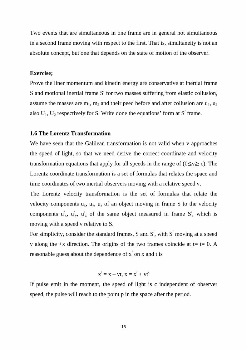
For simplicity, consider the standard frames, S and S/, with S/ moving at a speed
v along the +x direction. The origins of the two frames coincide at t= t= 0. A
reasonable guess about the dependence of x/ on x and t is
x/ = x – vt, x = x/ + vt/
If pulse emit in the moment, the speed of light is c independent of observer
speed, the pulse will reach to the point p in the space after the period.
16
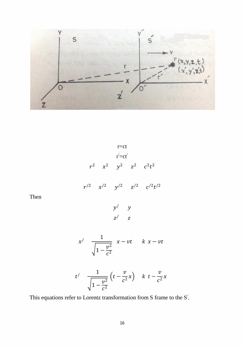
r=ct
r/=ct/
𝑟𝑟2 = 𝑥𝑥2 + 𝑦𝑦2 + 𝑧𝑧2 = 𝑐𝑐2𝑡𝑡2
𝑟𝑟/2 = 𝑥𝑥/2 + 𝑦𝑦/2 + 𝑧𝑧/2 = 𝑐𝑐/2𝑡𝑡/2
Then
𝑦𝑦/ = 𝑦𝑦
𝑧𝑧/ = 𝑧𝑧
𝑥𝑥/ =1
�1 − 𝑣𝑣2
𝑐𝑐2
(𝑥𝑥 − 𝑣𝑣𝑡𝑡) = 𝑘𝑘(𝑥𝑥 − 𝑣𝑣𝑡𝑡)
𝑡𝑡/ =1
�1 − 𝑣𝑣2
𝑐𝑐2
�𝑡𝑡 −𝑣𝑣𝑐𝑐2 𝑥𝑥� = 𝑘𝑘(𝑡𝑡 −
𝑣𝑣𝑐𝑐2 𝑥𝑥)
This equations refer to Lorentz transformation from S frame to the S/.
17
1.5.2 Time Dilation:
The fact, that observers in different inertial frames always measure different
time intervals between a pair of events.
Consider the two events has been happened in one location Xo in reference
inertial frame S; first event at time t1 and the second event at time t2, or the
event happened in location Xo at system S at time t1 and continued to the t2, then
the time interval between two events for observer have seating in the same
frame is:
To = t2 – t1
The time interval for observer seating in inertial frame S/ that moving uniformly
with speed v respect to the frame S, in direction XX/ is:
T/ = t/2 – t/
1
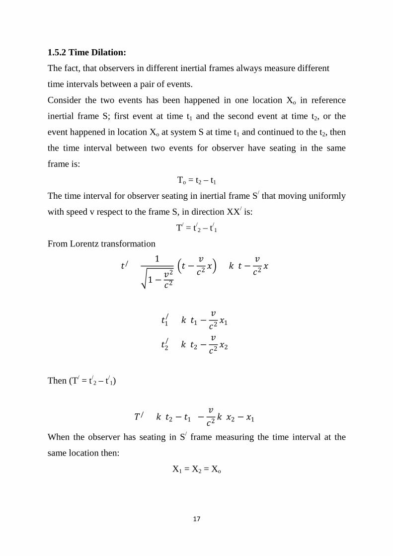
From Lorentz transformation
𝑡𝑡/ =1
�1 − 𝑣𝑣2
𝑐𝑐2
�𝑡𝑡 −𝑣𝑣𝑐𝑐2 𝑥𝑥� = 𝑘𝑘(𝑡𝑡 −
𝑣𝑣𝑐𝑐2 𝑥𝑥)
𝑡𝑡1/ = 𝑘𝑘(𝑡𝑡1 −
𝑣𝑣𝑐𝑐2 𝑥𝑥1)
𝑡𝑡2/ = 𝑘𝑘(𝑡𝑡2 −
𝑣𝑣𝑐𝑐2 𝑥𝑥2)
Then (T/ = t/2 – t/
1)
𝑇𝑇/ = 𝑘𝑘(𝑡𝑡2 − 𝑡𝑡1) −𝑣𝑣𝑐𝑐2 𝑘𝑘(𝑥𝑥2 − 𝑥𝑥1)
When the observer has seating in S/ frame measuring the time interval at the
same location then:
X1 = X2 = Xo
18
𝑇𝑇/ = 𝑘𝑘𝑇𝑇𝑜𝑜 =𝑇𝑇𝑜𝑜
�1 − 𝑣𝑣2
𝑐𝑐2
From the last equation:
First, if 0 ≤ 𝑣𝑣 ≤ 0.01𝑐𝑐 then 𝑇𝑇/ = 𝑇𝑇𝑜𝑜
Second, if v=c then T=∞
Third, if 0.01𝑐𝑐 < 𝑣𝑣 < 𝑐𝑐 then 𝑇𝑇/ > 𝑇𝑇𝑜𝑜
That mean the period for event happened in S frame that are measuring by
observer moving uniformly in speed v has been appear longer than the period
that measuring by other observer seating in the event frame, and vice versa.
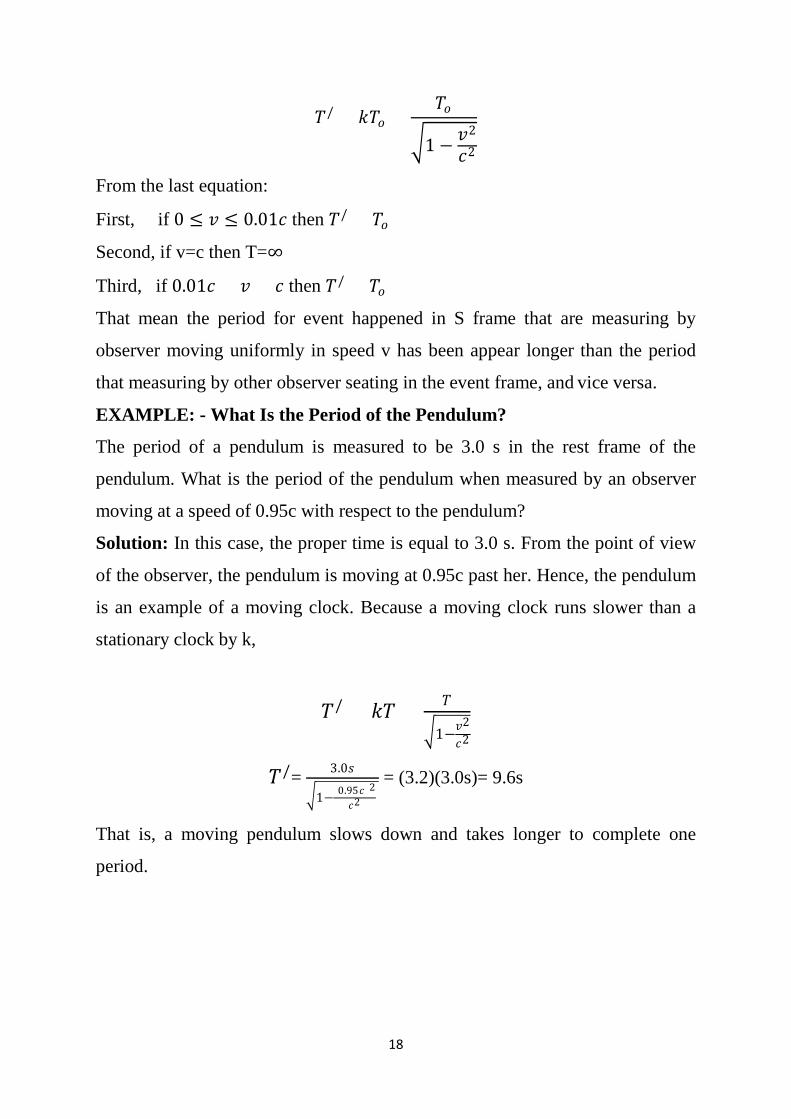
EXAMPLE: - What Is the Period of the Pendulum?
The period of a pendulum is measured to be 3.0 s in the rest frame of the
pendulum. What is the period of the pendulum when measured by an observer
moving at a speed of 0.95c with respect to the pendulum?
Solution: In this case, the proper time is equal to 3.0 s. From the point of view
of the observer, the pendulum is moving at 0.95c past her. Hence, the pendulum
is an example of a moving clock. Because a moving clock runs slower than a
stationary clock by k,
𝑇𝑇/ = 𝑘𝑘𝑇𝑇 = 𝑇𝑇
�1−𝑣𝑣2
𝑐𝑐2
𝑇𝑇/= 3.0𝑠𝑠
�1−(0.95𝑐𝑐)2
𝑐𝑐2 = (3.2)(3.0s)= 9.6s
That is, a moving pendulum slows down and takes longer to complete one
period.
19
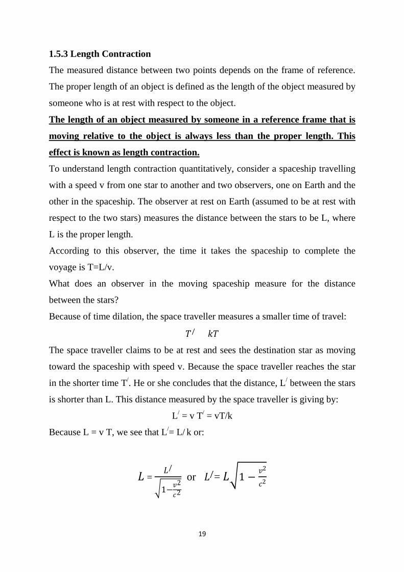
1.5.3 Length Contraction
The measured distance between two points depends on the frame of reference.
The proper length of an object is defined as the length of the object measured by
someone who is at rest with respect to the object.
To understand length contraction quantitatively, consider a spaceship travelling
with a speed v from one star to another and two observers, one on Earth and the
other in the spaceship. The observer at rest on Earth (assumed to be at rest with
respect to the two stars) measures the distance between the stars to be L, where
L is the proper length.
The length of an object measured by someone in a reference frame that is
moving relative to the object is always less than the proper length. This
effect is known as length contraction.
According to this observer, the time it takes the spaceship to complete the
voyage is T=L/v.
What does an observer in the moving spaceship measure for the distance
between the stars?
Because of time dilation, the space traveller measures a smaller time of travel:
𝑇𝑇/ = 𝑘𝑘𝑇𝑇
The space traveller claims to be at rest and sees the destination star as moving
toward the spaceship with speed v. Because the space traveller reaches the star
in the shorter time T/. He or she concludes that the distance, L/ between the stars
is shorter than L. This distance measured by the space traveller is giving by:
L/ = v T/ = vT/k
Because L = v T, we see that L/= L/ k or:
𝐿𝐿 = 𝐿𝐿/
�1−𝑣𝑣2
𝑐𝑐2
or 𝐿𝐿/= 𝐿𝐿�1 − 𝑣𝑣2
𝑐𝑐2
20
Where �1 − 𝑣𝑣2
𝑐𝑐2 is a factor less than 1.
This result may be interpreted as follows: If an object has a proper length L
when it is measured by an observer at rest with respect to the object, when it
moves with speed v in a direction parallel to its length, its length L/ is measured
to be shorter according to 𝐿𝐿/= 𝐿𝐿�1 − 𝑣𝑣2
𝑐𝑐2
Note that the length contraction takes place only along the direction of motion.
EXAMPLE: -
Solution: - The proper length of the ship is 100 m. The length measured as the
spaceship flies by is
The Contraction of a Spaceship. A spaceship is measured to be
100 m long while it is at rest with respect to an observer. If this spaceship now
flies by the observer with a speed of 0.99c, what length will the observer find
for the spaceship?
𝐿𝐿/= 𝐿𝐿�1 − 𝑣𝑣2
𝑐𝑐2
𝐿𝐿/= 100m�1 − (0.99𝑐𝑐)2
𝑐𝑐2 = 14m
Exercise: - An observer on Earth sees a spaceship at an altitude of
435 m moving downward toward the Earth at 0.970c. What is the
altitude of the spaceship as measured by an observer in the spaceship?
Homework.
21
Chapter 2 RELATIVITY II
2.1 Relativistic Speed
Assume an objective moving with speed u to respect of S observer and with
speed u/ for S/ observer that moving uniformly in v speed to the S system, so the
speed component can take be the form.
ux = 𝑑𝑑𝑥𝑥𝑑𝑑𝑡𝑡
, uy = 𝑑𝑑𝑦𝑦𝑑𝑑𝑡𝑡
, uz = 𝑑𝑑𝑧𝑧𝑑𝑑𝑡𝑡
In addition, the speed components for S/can are taking the form.
𝑢𝑢𝑥𝑥/ =𝑑𝑑𝑥𝑥
/
𝑑𝑑𝑡𝑡 , 𝑢𝑢𝑦𝑦
/ =𝑑𝑑𝑦𝑦/
𝑑𝑑𝑡𝑡 , 𝑢𝑢𝑧𝑧
/ =𝑑𝑑𝑧𝑧/
𝑑𝑑𝑡𝑡
In order to find the relation between u and u/, we have to use the Lorentz
transformation.
From equations below;
𝑑𝑑𝑥𝑥/ = 𝑘𝑘 (𝑑𝑑𝑥𝑥 − 𝑣𝑣𝑑𝑑𝑡𝑡)
𝑑𝑑𝑦𝑦/ = 𝑑𝑑𝑦𝑦
𝑑𝑑𝑧𝑧/ = 𝑑𝑑𝑧𝑧
𝑑𝑑𝑡𝑡/ = 𝑘𝑘 (𝑑𝑑𝑡𝑡 −𝑣𝑣𝑐𝑐2 𝑑𝑑𝑥𝑥)
After solve the above equations;
𝑢𝑢𝑥𝑥/ =
𝑢𝑢𝑥𝑥 − 𝑣𝑣
1 − 𝑣𝑣𝑢𝑢𝑥𝑥𝑐𝑐2
𝑢𝑢𝑦𝑦/ =
𝑢𝑢𝑦𝑦𝑘𝑘(1 − 𝑣𝑣𝑢𝑢𝑥𝑥𝑐𝑐2 )
𝑢𝑢𝑧𝑧/ =
𝑢𝑢𝑧𝑧𝑘𝑘(1 − 𝑣𝑣𝑢𝑢𝑥𝑥𝑐𝑐2 )
22
The reverse transformation;
𝑢𝑢𝑥𝑥 =𝑢𝑢𝑥𝑥
/ + 𝑣𝑣
1 + 𝑣𝑣𝑢𝑢𝑥𝑥/
𝑐𝑐2
𝑢𝑢𝑦𝑦 =𝑢𝑢𝑦𝑦
/
𝑘𝑘(1 + 𝑣𝑣𝑢𝑢𝑥𝑥/
𝑐𝑐2 )
𝑢𝑢𝑧𝑧 =𝑢𝑢𝑧𝑧
/
𝑘𝑘(1 + 𝑣𝑣𝑢𝑢𝑥𝑥/
𝑐𝑐2 )
As one can see the speed𝑢𝑢𝑦𝑦/ , 𝑢𝑢𝑧𝑧
/ and𝑢𝑢𝑦𝑦 , 𝑢𝑢𝑧𝑧 depend 𝑢𝑢𝑥𝑥 or 𝑢𝑢𝑥𝑥/ in less the
transformations are not including x, because the different in time for both
observer in systems S and S/.
Also the Lorentz transformation for speed can be changing to the Galilean
transformations if the speed amounts v and ux very small with respect for light
speed.
From the above we can conclude that:
1- The speed of light is independent on relativistic motion for both the
source and observer.
2- The speed of objective cannot be more than the speed of light.
3- Galilean transformations for speed are correct just if the speed of
objective is very small compare to the speed of light, also are not correct
for the objectives moving with high speed close to the light speed.
23
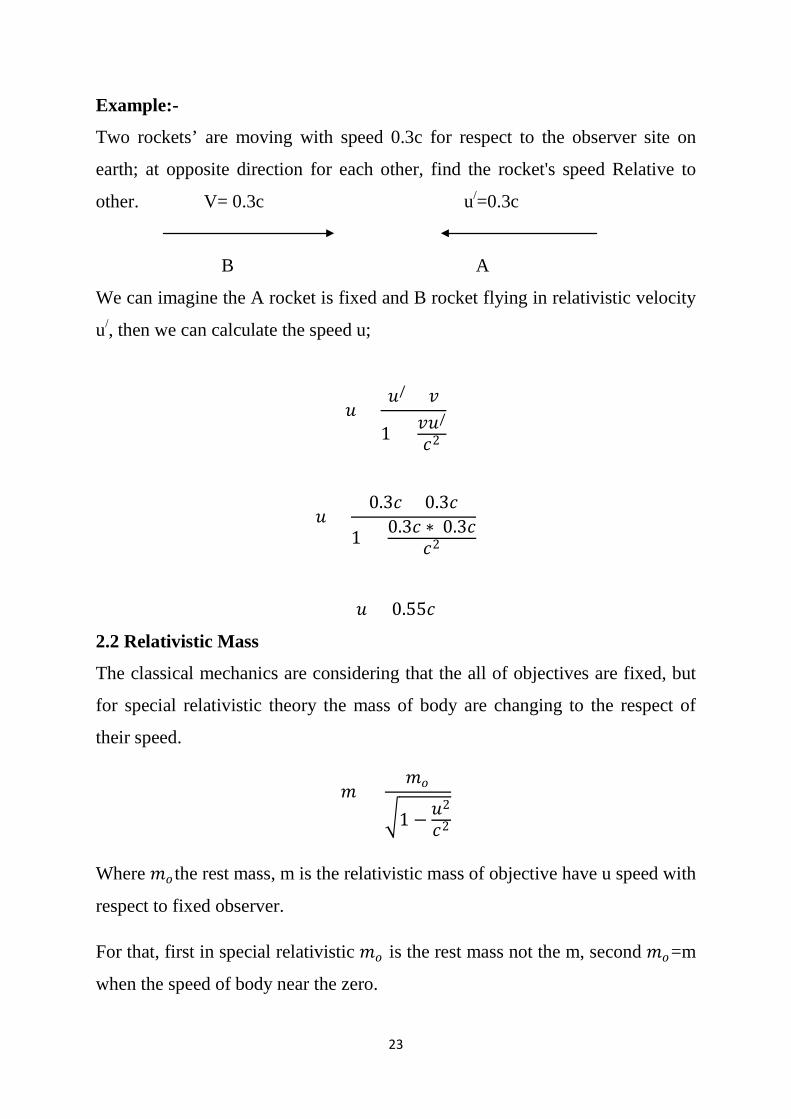
Example:-
Two rockets’ are moving with speed 0.3c for respect to the observer site on
earth; at opposite direction for each other, find the rocket's speed Relative to
other. V= 0.3c u/=0.3c
B A
We can imagine the A rocket is fixed and B rocket flying in relativistic velocity
u/, then we can calculate the speed u;
𝑢𝑢 =𝑢𝑢/ + 𝑣𝑣
1 + 𝑣𝑣𝑢𝑢/
𝑐𝑐2
𝑢𝑢 =0.3𝑐𝑐 + 0.3𝑐𝑐
1 + 0.3𝑐𝑐 ∗ 0.3𝑐𝑐𝑐𝑐2
𝑢𝑢 = 0.55𝑐𝑐
2.2 Relativistic Mass
The classical mechanics are considering that the all of objectives are fixed, but
for special relativistic theory the mass of body are changing to the respect of
their speed.
𝑚𝑚 = 𝑚𝑚𝑜𝑜
�1 − 𝑢𝑢2
𝑐𝑐2
Where 𝑚𝑚𝑜𝑜 the rest mass, m is the relativistic mass of objective have u speed with
respect to fixed observer.
For that, first in special relativistic 𝑚𝑚𝑜𝑜 is the rest mass not the m, second 𝑚𝑚𝑜𝑜=m
when the speed of body near the zero.
24
Example:-
What is the velocity that is required for particle has relativistic mass that are
double of rest mass.
m =2𝑚𝑚𝑜𝑜
𝑚𝑚 = 𝑚𝑚𝑜𝑜
�1 − 𝑢𝑢2
𝑐𝑐2
Then
�1 − 𝑢𝑢2
𝑐𝑐2 = 𝑚𝑚𝑜𝑜𝑚𝑚
= 12
1 − 𝑢𝑢2
𝑐𝑐2 = 14
u = 0.866c
2.3 Relativistic momentum:
At classical mechanics the momentum Pc can be define for particle have a mass
m and speed u,
pc= mu=mou
Relativistic theory considering the mass changing to respect of their speed, then
the momentum can be writ as showing below.
P=𝑚𝑚𝑢𝑢 = 𝑚𝑚𝑜𝑜𝑢𝑢
�1−𝑢𝑢2
𝑐𝑐2
Where p is the relativistic momentum, also m is the relativistic mass.
25
Exercise: An electron, which has a mass of 9.11*1031 kg, moves with a speed of
0.750c, find its relativistic momentum and compare this with the momentum
calculated from the classical expression pc.
2.4 Relativistic Energy
The kinetic energy in classical form can write to the respect of rest mass mo and
speed u;
Ekc = 12 mo𝑢𝑢2
But in relativistic form
Ek= 𝑚𝑚𝑜𝑜𝑐𝑐2[ 1
�1−𝑢𝑢2
𝑐𝑐2
− 1] = k 𝑚𝑚𝑜𝑜𝑐𝑐2 −𝑚𝑚𝑜𝑜𝑐𝑐2
Ek = 12 mo𝑢𝑢2= Ekc
The constant term moc2, which is independent of the speed, called the rest
energy of the particle.
The term E, which depends on the particle speed, is therefore the sum of the
kinetic and rest energies. We define it is the total energy E=k𝑚𝑚𝑜𝑜𝑐𝑐2, that is;
E = Ek + moc2
In many situations, the momentum or energy of a particle is measured rather
than its speed. It is therefore useful to have an expression relating the total
energy E to the relativistic momentum p. This is accomplished using E and p.
By squaring these equations and subtracting, we can eliminate u. The result,
after some algebra, is;
E2 = p2c2 + (moc2)2
26
Example: An electron has a speed u=0.850c. Find its total energy and kinetic
energy in electron volts, if the rest energy of the electron is 0.511MeV.
Solution:
The total energy is;
E=k 𝑚𝑚𝑜𝑜𝑐𝑐2
E= 𝑚𝑚𝑜𝑜𝑐𝑐2
�1−𝑢𝑢2
𝑐𝑐2
= 0.511𝑀𝑀𝑀𝑀𝑉𝑉
�1−(0.85𝑐𝑐)2
𝑐𝑐2
= 0.97Mev
The kinetic energy is;
Ek= E - 𝑚𝑚𝑜𝑜𝑐𝑐2=0.459MeV
Exercise: The total energy of a proton is three times its rest energy. Where the
mass of proton is mp =1.67 *1027kg
a- Find the proton’s rest energy in electron volts.
b- With what speed is the proton moving?
c- Determine the kinetic energy of the proton in electron volts.
d- What is the proton’s momentum?
27
2.5 Relativistic Force
The force in classical mechanics is defined as a time rate of change momentum.
Fc = 𝑑𝑑𝑑𝑑𝑐𝑐𝑑𝑑𝑡𝑡
= 𝑑𝑑(𝑚𝑚𝑜𝑜𝑢𝑢)
𝑑𝑑𝑡𝑡 = 𝑚𝑚𝑜𝑜
𝑑𝑑𝑢𝑢𝑑𝑑𝑡𝑡
However, the mass are not fixed in relativistic theory, for that the force are
affecting on the relativistic mass and were defined as a time rate of change
relativistic momentum.
F = 𝑑𝑑𝑑𝑑𝑑𝑑𝑡𝑡
= 𝑑𝑑(𝑚𝑚𝑢𝑢 )𝑑𝑑𝑡𝑡
= m 𝑑𝑑𝑢𝑢𝑑𝑑𝑡𝑡
+u 𝑑𝑑𝑚𝑚𝑑𝑑𝑡𝑡
Special cases
u≪c then m ------mo and 𝑑𝑑𝑚𝑚𝑑𝑑𝑡𝑡
----- 0
2.6 Relativistic Synchronization (instantaneous)
Assume there are two events have been happened in two locations x1, x2 at S
system, stationary observer in this frame recorded these events at one time
(instantaneously) t1=t2. So are these events appear instantaneously for observer
site in S/ that moving uniformly in speed v to respect of S, is 𝑡𝑡1/ = 𝑡𝑡2
/ or not.
𝑡𝑡1/ = 𝑘𝑘 (𝑡𝑡1 −
𝑣𝑣𝑐𝑐2 𝑥𝑥1)
𝑡𝑡2/ = 𝑘𝑘 (𝑡𝑡2 −
𝑣𝑣𝑐𝑐2 𝑥𝑥2)
After subtracting the above equations;
𝑡𝑡2/-𝑡𝑡1
/= k (𝑡𝑡2-𝑡𝑡1)- 𝑣𝑣𝑐𝑐2 (𝑥𝑥2 − 𝑥𝑥1)
As we know t1=t2
Then 𝑡𝑡2/-𝑡𝑡1
/= - 𝑣𝑣𝑐𝑐2 (𝑥𝑥2 − 𝑥𝑥1)
Also 𝑣𝑣𝑐𝑐2 (𝑥𝑥2 − 𝑥𝑥1) ≠ 0 then 𝑡𝑡2
/ ≠ 𝑡𝑡1/
28
CHAPTER 3
The Electrical, Optical Properties and band Theory
3.1 Determination of Electric Charge
Electric charge is the physical property of matter that causes it to experience a
force when placed in an electromagnetic field. There are two types of electric
charges: positive and negative. Like charges repel and unlike attract.
The electric charge, usually denoted as e or sometimes q, is the electric charge
carried by a single proton, or equivalently, the magnitude of the electric charge
carried by a single electron, which has charge −e. This charge is a fundamental
physical constant. This charge has a measured value of approximately 1.6×10⁻¹⁹
coulombs.
3.2 Millikan Method of Drop Model
The magnitude of the elementary charge was first measured in Robert A.
Millikan's noted oil drop experiment in 1909.
The experiment entailed observing tiny charged droplets of oil between two
horizontal metal electrodes. First, with zero applied electric field, the terminal
velocity of a droplet was measured. Then an adjustable voltage was applied
between the plates to induce an electric field, and the voltage was adjusted until
the drops were suspended in mechanical equilibrium, indicating that the
electrical force and the gravitational force were balanced.
Now using the known electric field, Millikan could determine the charge on the
oil droplet. By repeating the experiment for many droplets, they confirmed that
the charges were all small integer multiples of a certain base value, which was
found to be 1.5926×10⁻¹⁹ C, within 1% of the currently accepted value of
1.602×x10−19 C. They proposed that this was the (negative of the) charge of a
single electron.
29
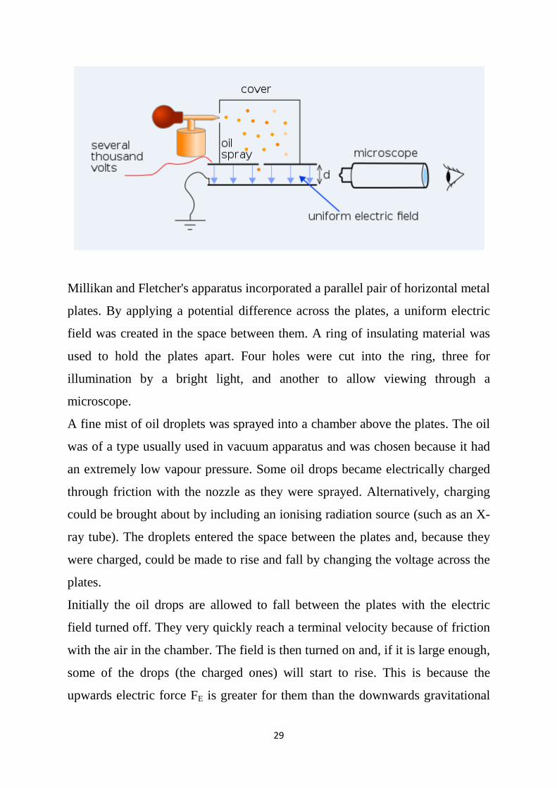
Millikan and Fletcher's apparatus incorporated a parallel pair of horizontal metal
plates. By applying a potential difference across the plates, a uniform electric
field was created in the space between them. A ring of insulating material was
used to hold the plates apart. Four holes were cut into the ring, three for
illumination by a bright light, and another to allow viewing through a
microscope.
A fine mist of oil droplets was sprayed into a chamber above the plates. The oil
was of a type usually used in vacuum apparatus and was chosen because it had
an extremely low vapour pressure. Some oil drops became electrically charged
through friction with the nozzle as they were sprayed. Alternatively, charging
could be brought about by including an ionising radiation source (such as an X-
ray tube). The droplets entered the space between the plates and, because they
were charged, could be made to rise and fall by changing the voltage across the
plates.
Initially the oil drops are allowed to fall between the plates with the electric
field turned off. They very quickly reach a terminal velocity because of friction
with the air in the chamber. The field is then turned on and, if it is large enough,
some of the drops (the charged ones) will start to rise. This is because the
upwards electric force FE is greater for them than the downwards gravitational
30
force Fg. A likely looking drop is collected and kept in the middle of the field of
view by alternately switching off the voltage until all the other drops have
fallen. The experiment is then continuing with this one drop. The drop is
allowed to fall and its terminal velocity v1 in the absence of an electric field is
calculated. The drag force acting on the drop can then be calculated.
FE = Fg
FE =qE & Fg = mg
qE = mg
E= 𝑉𝑉𝐷𝐷
Then
q = 𝑚𝑚𝑚𝑚𝐷𝐷𝑉𝑉
Where q is the charge, m the oil drop mass, D the distance between two plates
and g the gravity.
Example; Oil drop suspended between two plates after applied different
potential (8 Volts), find the mass of drop if the total charges is 3.2 * 10-15 C and
the distance between the plates are 2cm, also what is the drop diameter if the oil
density is 850 kg/m3. Assume the gravity is 10 m/Sec2
q = 𝑚𝑚𝑚𝑚𝐷𝐷𝑉𝑉
m = 𝑘𝑘𝑉𝑉𝑚𝑚𝐷𝐷
V (sphere) = (4/3)𝜋𝜋𝑟𝑟3
31
3.3 The Free Electron Theory
A model of a metal in which the free electrons, that is, those giving rise to the
conductivity, are regarded as moving in a potential (due to the metal ions in the
lattice and to all the remaining free electrons) which is approximated as constant
everywhere inside the metal. Also known as Somerfield model; Somerfield
theory.
The treatment of a metal as containing a gas of electrons completely free to
move within it. The theory was originally proposed in 1900 to describe and
correlate the electrical and thermal properties of metals. Quantum mechanics
became the basis for the theory of most of the general properties of simple
metals such as sodium, with one free electron per atom, magnesium with two,
and aluminium with three. Transition metals, such as iron, have partially filled
electronic d states and are not treated by the free-electron model.
For that,
Metals are good conductors (both electrical and thermal).
Electronic heat capacity has an additional (temperature dependent)
contribution from the electrons.
3.4 Expression for Electrical Conductivity
The most important characteristic of a metal is its electrical conductivity; it is a
measure of a material's ability to conduct an electric current also the specific
conductance, is a measurement of the electrical conductance per unit distance in
an electrolytic or aqueous solution. In metal, the electrically charged particles
comprise ions and electrons. The ionic charge carriers comprise the cations,
anions, and foreign ions (e.g. impurity ions, dopant ions and protons) and the
electronic charge carriers are the electrons and electron holes.
Electrical conductivity or specific conductance is the reciprocal of electrical
resistivity, and measures a material's ability to conduct an electric current. It is
commonly represented by the Greek letter σ (sigma). Its SI unit is Siemens per
metre (S/m).
32
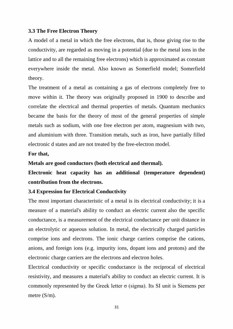
In solid-state physics, the valence band and conduction band are the bands
closest to the Fermi level and thus determine the electrical conductivity of the
solid. The valence band is the highest range of electron energies in which
electrons are normally present at absolute zero temperature, while the
conduction band is the lowest range of vacant electronic states. On a graph of
the electronic band structure of a material, the valence band is located below the
Fermi level, while the conduction band is located above it. This distinction is
meaningless in metals as the highest band is partially filled, taking on the
properties of both the valence and conduction bands.
The formula for conductance should produce a quantity with dimensions
independent of distance, like Ohm's Law for electrical resistance:
𝑅𝑅 =𝑉𝑉𝐼𝐼
and conductance:
𝐺𝐺 =𝐼𝐼𝑉𝑉
33
From the electrical formula: R= 𝜌𝜌 𝑥𝑥𝐴𝐴
, where ρ is resistivity, x is length, and A
is cross-sectional area, we have G = k𝐴𝐴𝑥𝑥
, where G is conductance, k is
conductivity, x is length, and A is cross-sectional area.
3.5 Expression for Thermal Conductivity
Thermal conductivity is the property of a material to conduct heat; it’s evaluated
primarily in terms of Fourier’s Law for heat conduction.
Heat transfer occurs at a lower rate across materials of low thermal conductivity
than across materials of high thermal conductivity.
Correspondingly, materials of high thermal conductivity are widely used in heat
sink applications and materials of low thermal conductivity are used as thermal
insulation.
The thermal conductivity of a material may depend on temperature. The
reciprocal of thermal conductivity is called thermal resistivity.
U= k𝐴𝐴∆𝑥𝑥
Where U is the conductance and ∆𝑥𝑥=x2-x1, Fourier's law of heat transfer is;
Q= U∆𝑇𝑇
Where ∆𝑇𝑇=T2-T1, The reciprocal of conductance is resistance, R, given by:
R= ∆𝑇𝑇𝑘𝑘
34
3.6 Light
Light is electromagnetic radiation within a certain portion of the
electromagnetic spectrum. The word usually refers to visible light, which is
visible to the human eye and is responsible for the sense of sight. Visible light is
usually defined as having wavelengths in the range of 400–700 nanometres
(nm), or 4.00 × 10⁻⁷ to 7.00 × 10⁻⁷ m, between the infrared (with longer
wavelengths) and the ultraviolet (with shorter wavelengths).
Electromagnetic spectrum and visible light;
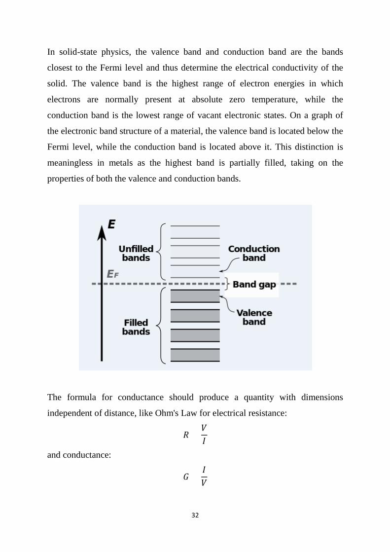
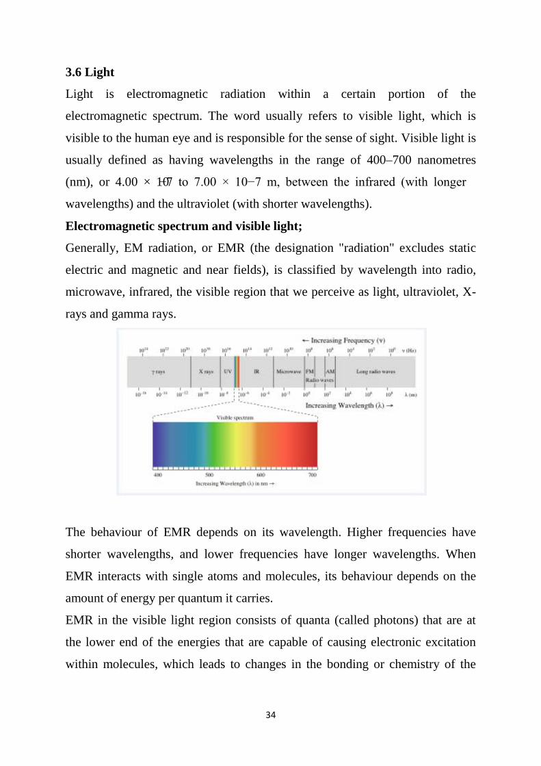
Generally, EM radiation, or EMR (the designation "radiation" excludes static
electric and magnetic and near fields), is classified by wavelength into radio,
microwave, infrared, the visible region that we perceive as light, ultraviolet, X-
rays and gamma rays.
The behaviour of EMR depends on its wavelength. Higher frequencies have
shorter wavelengths, and lower frequencies have longer wavelengths. When
EMR interacts with single atoms and molecules, its behaviour depends on the
amount of energy per quantum it carries.
EMR in the visible light region consists of quanta (called photons) that are at
the lower end of the energies that are capable of causing electronic excitation
within molecules, which leads to changes in the bonding or chemistry of the
35
molecule. At the lower end of the visible light spectrum, EMR becomes
invisible to humans (infrared).
3.7 Optical properties
The importance of the optical properties of materials lies through the use in the
identification of the components and materials in general, which is including the
Absorbance, Luminosity, Photosensitivity, Reflectivity, Refractive index,
Scattering, etc...
Absorption: In physics, absorption of electromagnetic radiation is the way
in which the energy of a photon is taken up by matter, typically the
electrons of an atom. Thus, the electromagnetic energy is transformed into
internal energy of the absorber. The term absorption refers to the physical
process of absorbing light, while absorbance does not always measure
absorption: it measures attenuation (of transmitted radiant power). Absorption is
one reason of attenuation.
Luminosity: luminosity is the total amount of energy emitted by a star,
galaxy, or other astronomical object per unit time. It is relating to the
brightness, which is the luminosity of an object in a given spectral region.
In SI, unit’s luminosity is measured in joules per second or watts. Values for
luminosity are often given in the terms of the luminosity of the Sun, which has a
total power output of 3.846×1026 W.
Photosensitivity: Photosensitivity is the amount to which an object reacts upon
receiving photons, especially visible light.
Reflectance: Reflectance of the surface of a material is its effectiveness in
reflecting radiant energy. It is the fraction of incident electromagnetic power
that is reflected at an interface. The reflectance spectrum of spectral reflectance
curve is the plot of the reflectance as a function of wavelength.
Refractive index: In optics, the refractive index or index of refraction n of a
material is a dimensionless number that describes how light propagates through
that medium. It is defined as;
36
𝑛𝑛 =𝑐𝑐𝑣𝑣
Where c is the speed of light in vacuum and v is the phase velocity of light in
the medium. For example, the refractive index of water is 1.333; meaning that
light travels 1.333 times faster in a vacuum than it does in water. When the light
entering inside the material the refractive index is determined how much light
bent or refracted.
Scattering: Scattering is a general physical process where some forms of
radiation, such as light, sound, or moving particles, are forced to deviate
from a straight trajectory by one or more paths due to localized non-
uniformities in the medium through which they pass. In conventional use,
this also includes deviation of reflected radiation from the angle predicted by
the law of reflection. Reflections that undergo scattering are often called diffuse
reflections and scattered reflections are called specular (mirror-like) reflections.
Scattering may also refer to particle-particle collisions between molecules,
atoms, electrons, photons and other particles. Examples are cosmic rays
scattering by the Earth's upper atmosphere; particle collisions inside particle
accelerators; electron scattering by gas atoms in fluorescent lamps; and neutron
scattering inside nuclear reactors.
Transmittance: Transmittance of the surface of a material is its effectiveness in
transmitting radiant energy. It is the fraction of incident electromagnetic
power that is transmitted through a sample, in contrast to the transmission
coefficient, which is the ratio of the transmitted to incident electric field.
Internal transmittance refers to energy loss by absorption, whereas (total)
transmittance is that due to absorption.
37
3.8 Energy Band
Energy bands consisting of a large number of closely spaced energy levels exist
in crystalline materials. The bands can be thought of as the collection of the
individual energy levels of electrons surrounding each atom. The wave
functions of the individual electrons, however, overlap with those of electrons
confined to neighbouring atoms.
The energy band model is crucial to any detailed treatment of semiconductor
devices. It provides the framework needed to understand the concept of an
energy band gap and that of conduction in an almost filled band as described by
the empty states.
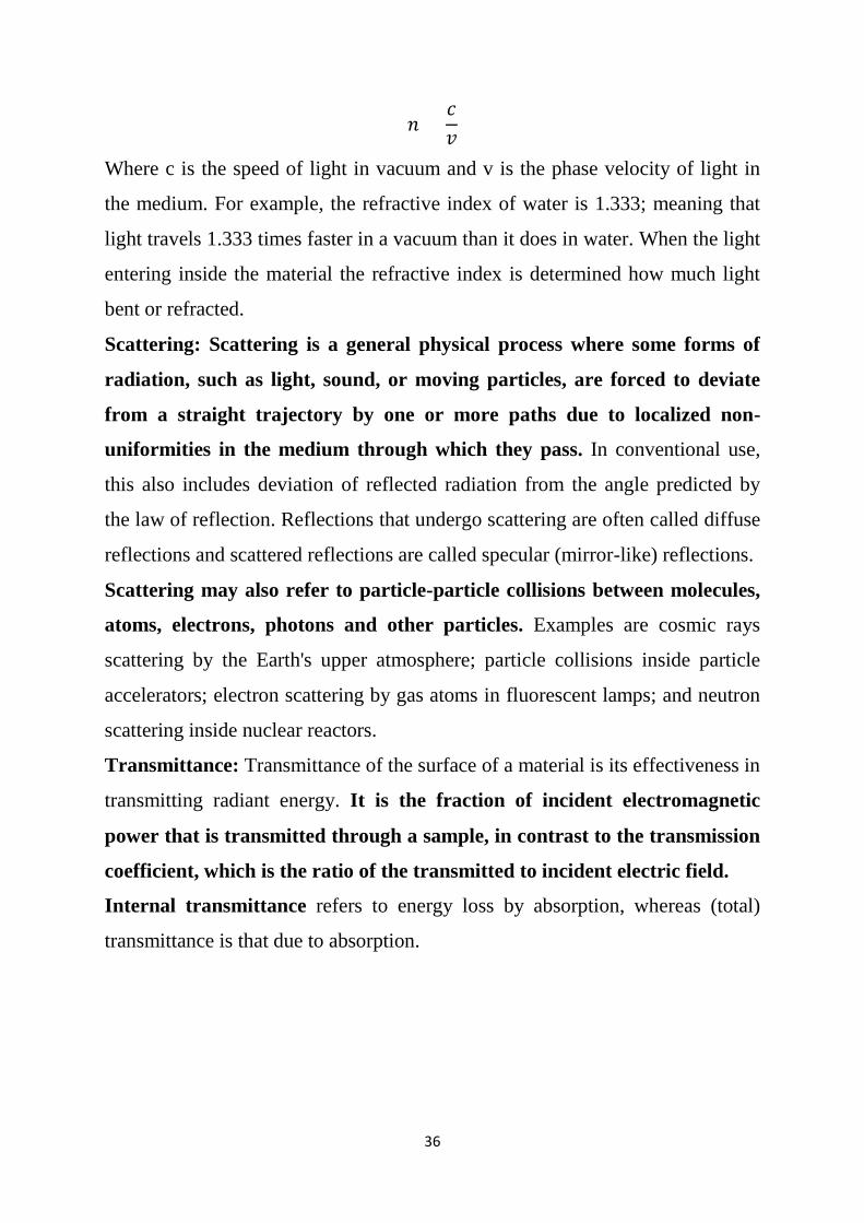
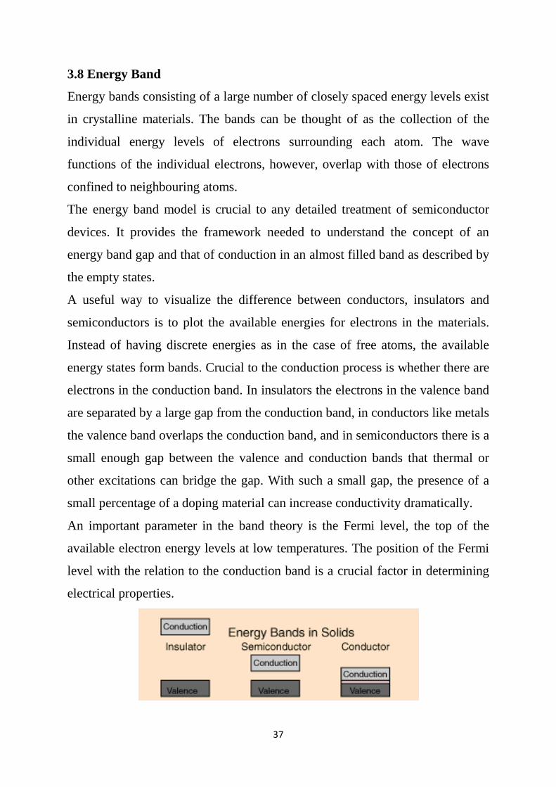
A useful way to visualize the difference between conductors, insulators and
semiconductors is to plot the available energies for electrons in the materials.
Instead of having discrete energies as in the case of free atoms, the available
energy states form bands. Crucial to the conduction process is whether there are
electrons in the conduction band. In insulators the electrons in the valence band
are separated by a large gap from the conduction band, in conductors like metals
the valence band overlaps the conduction band, and in semiconductors there is a
small enough gap between the valence and conduction bands that thermal or
other excitations can bridge the gap. With such a small gap, the presence of a
small percentage of a doping material can increase conductivity dramatically.
An important parameter in the band theory is the Fermi level, the top of the
available electron energy levels at low temperatures. The position of the Fermi
level with the relation to the conduction band is a crucial factor in determining
electrical properties.
38
Band gap, also called an energy gap or band gap, is an energy range in a solid
where no electron states can exist. In above graphs of the electronic band
structure of solids, the band gap generally refers to the energy difference (in
electron volts) between the top of the valence band and the bottom of the
conduction band in insulators and semiconductors.
Exercise:
Estimate the electric field strength required to produce conduction in diamond,
an excellent insulator at room temperature. Assume a mean free path of (5*10-8
m) and an energy gap of 7eV in diamond.
39
CHAPTER 4
Positive Ray and Particle Properties of Waves
4.1 Positive Rays and their Properties
Cathode rays consist of negatively charged particles called electrons. These
electrons move away from cathode with very high speeds. These fast moving
electrons collide with the molecules of the gas in the tube, split the molecule
into atoms, and remove one or more electrons from the atoms. Thus, the atoms
get converted into the positive ions due to loss of electrons. These positive ions
get attracted by the negative electrode, and pass through the holes in the
electrode plate to produce a glow only the glass wall of the discharge tube. A
stream of these positively charged particles is called a positive ray (or anode
ray).
Properties of positive rays
1. Positive rays consist of positively charged particles.
2. The nature of these rays depends on the gas used in the discharge tube.
3. These rays travel in straight lines.
4. These rays are deflected by an electrical field, and bend towards the negative
plate. Thus, the deflection of the positive rays is in a direction opposite to that
shown by the cathode rays.
5. These rays are also deflected by the magnetic fields in the direction opposite
to that of the cathode rays.
6. These rays can produce mechanical as well as chemical effects.
7. The ratio of charge (e) to mass (m), i.e.,(e/m) for the particles in the positive
rays is not the same for all gases.
8. The ratio e / m for the positive rays is very low as compared to the e / m
value for cathode rays.
Then an anode ray (also positive ray or canal ray) is a beam of positive ions that
is created by certain types of gas discharge tubes.
40
4.2 Electric Field and Magnetic Field
An electromagnetic field (also EM field) is a physical field produced by
electrically charged objects. It affects the behaviour of charged objects in the
vicinity of the field. The electromagnetic field extends indefinitely throughout
space and describes the electromagnetic interaction. It is one of the four
fundamental forces of nature (the others are gravitation, weak interaction and
strong interaction).
The field can be viewed as the combination of an electric field and a magnetic
field. The electric field is produced by stationary charges, and the magnetic field
by moving charges (currents); these two are often described as the sources of
the field.
4.3 Blackbody Radiation
A blackbody refers to an opaque object that emits thermal radiation. A perfect
blackbody is one that absorbs all incoming light and does not reflect any. At
room temperature, such an object would appear to be perfectly black (hence the
term blackbody). However, if heated to a high temperature, a blackbody will
begin to glow with thermal radiation.
Experimentally the total power per unit area emitted at all frequencies by a hot
solid, e total was proportional to the fourth power of its absolute temperature.
Therefore, Stefan’s law can write.
Where e total is the power per unit area emitted at the surface of the blackbody at
all frequencies, ef is the power per unit area per unit frequency emitted by the
blackbody, T is the absolute temperature of the body and 𝜎𝜎 = 5.67 * 10-8 W m-2
K-4 is the Stefan–Boltzmann constant given by that is not an ideal radiator will
obey the same general law but with a coefficient, a, less than 1.
41
Exercise: Estimate the surface temperature of the Sun from the following
information. The Sun’s radius is given by Rs = 7.0 * 108 m. The average Earth
Sun distance is R =1.5 * 1011 m. The power per unit area (at all frequencies)
from the Sun is measured at the Earth to be 1400 W/m2. Assume that the Sun is
a blackbody.
As known that glowing solids emit continuous spectra rather than the
bands or lines emitted by heated gases. (See Figure below) In 1859, Gustav
Kirchhoff proved a theorem as important as his circuit loop theorem when he
showed by arguments based on thermodynamics that for anybody in thermal
equilibrium with radiation the emitted power is proportional to the power
absorbed.
More specifically,
where ef is the power emitted per unit area per unit frequency by a particular
heated object, Af is the absorption power (fraction of the incident power
absorbed per unit area per unit frequency by the heated object), and J( f, T)
is a universal function (the same for all bodies) that depends only on f, the light
frequency, and T, the absolute temperature of the body. A blackbody is defined
as an object that absorbs all the electromagnetic radiation falling on it and
consequently appears black.
It has Af =1 for all frequencies and so Kirchhoff’s
theorem for a blackbody becomes
A perfect black body:
the body in thermodynamic equilibrium absorbs all
light that strikes it and radiates energy according to the radioactive
emissive power for temperature T.
42
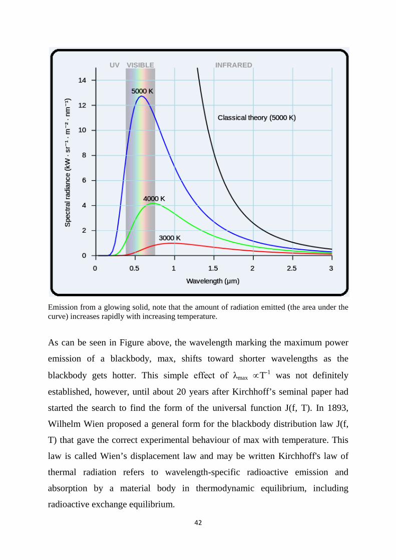
Emission from a glowing solid, note that the amount of radiation emitted (the area under the curve) increases rapidly with increasing temperature.
As can be seen in Figure above, the wavelength marking the maximum power
emission of a blackbody, max, shifts toward shorter wavelengths as the
blackbody gets hotter. This simple effect of λmax ∝T-1 was not definitely
established, however, until about 20 years after Kirchhoff’s seminal paper had
started the search to find the form of the universal function J(f, T). In 1893,
Wilhelm Wien proposed a general form for the blackbody distribution law J(f,
T) that gave the correct experimental behaviour of max with temperature. This
law is called Wien’s displacement law and may be written Kirchhoff's law of
thermal radiation refers to wavelength-specific radioactive emission and
absorption by a material body in thermodynamic equilibrium, including
radioactive exchange equilibrium.
43
Where λmax max is the wavelength in meters corresponding to the blackbodies
maximum intensity and T is the absolute temperature of the surface of the
object emitting the radiation. The ratio of its emissive power to its
dimensionless coefficient of absorption is equal to a universal function only of
radioactive wavelength and temperature. That universal function describes the
perfect blackbody emissive power.
Assuming that the peak sensitivity of the human eye (which occurs at about 500
nm—blue-green light) coincides with max for the Sun (a blackbody), we can
check the consistency of Wien’s displacement law with Stefan’s law by
recalculating the Sun’s surface temperature:
Kirchhoff's law states that: For a body of any arbitrary material emitting
and absorbing thermal electromagnetic radiation at every wavelength in
thermodynamic equilibrium.
A black body in thermal equilibrium has two notable properties:
It is an ideal emitter: at every frequency, it emits as much energy as – or
more energy than – any other body at the same temperature.
It is a diffuse emitter: the energy is radiated isotropically, independent of
direction.
Enter Planck
Planck's law: is describes the electromagnetic radiation emitted by a black
body in thermal equilibrium at a definite temperature T.
The Planck constant (denoted h, also called Planck's constant) is a physical
constant that is the quantum of action, central in quantum mechanics.
44
First recognized in 1900 by Max Planck, it was originally the proportionality
constant between the minimal increment of energy, E, of a hypothetical
electrically charged oscillator in a cavity that contained black body radiation,
and the frequency, f, of its associated electromagnetic wave.
The light quantum behaved in some respects as an electrically neutral particle,
as opposed to an electromagnetic wave. It was eventually called the photon.
The Planck–Einstein relation connects the particulate photon energy E with its
associated wave frequency f:
This energy is extremely small in terms of ordinarily perceived everyday
objects.
Since the frequency f, wavelength λ, and speed of light C are related by f=c/ λ,
the relation can also be expressed as;
This leads to another relationship involving the Planck constant. With p
denoting the linear momentum of a particle (not only a photon, but also other
fine particles as well),
The spectral radiance of a body, Bν: describes the amount of energy it gives
off as radiation of different frequencies. It is measured in terms of the power
emitted per unit area of the body, per unit solid angle that the radiation is
measured over, per unit frequency. Planck showed that the spectral radiance of a
body at absolute temperature T is given by;
45
Where kB the Boltzmann constant, h the Planck constant and C the speed of
light in the medium, whether material or vacuum. The spectral radiance can also
be measured per unit wavelength instead of per unit frequency. In this case, it is
given by
The law may also be expressed in other terms, such as the number of photons
emitted at a certain wavelength, or the energy density in a volume of radiation.
The SI units of Bν are W·sr−1·m−2·Hz−1, while those of Bλ are W·sr−1·m−3.
Every physical body spontaneously and continuously emits electromagnetic
radiation. Near thermodynamic equilibrium, the emitted radiation is nearly
described by Planck's law. Because of its dependence on temperature, Planck
radiation is said to be thermal radiation. The higher the temperature of a body
the more radiation it emits at every wavelength. Planck radiation has a
maximum intensity at a specific wavelength that depends on the temperature.
For example, at room temperature (~300 K), a body emits thermal radiation that
is mostly infrared and invisible. At higher temperatures the amount of infrared
radiation increases and can be felt as heat, and the body glows visibly red. At
even higher temperatures, a body is dazzlingly bright yellow or blue-white and
emits significant amounts of short wavelength radiation, including ultraviolet
and even x-rays. The surface of the sun (~6000 K) emits large amounts of both
infrared and ultraviolet radiation; its emission is peaked in the visible spectrum.
Planck radiation is the greatest amount of radiation that anybody at thermal
equilibrium can emit from its surface, whatever its chemical composition or
surface structure. The passage of radiation across an interface between media
can be characterized by the emissivity of the interface (the ratio of the actual
46
radiance to the theoretical Planck radiance), usually denoted by the symbol ε. It
is in general dependent on chemical composition and physical structure, on
temperature, on the wavelength, on the angle of passage, and on the
polarization. The emissivity of a natural interface is always between ε = 0 and 1.
In the limit of low frequencies (i.e. long wavelengths), Planck's law tends to the
Rayleigh–Jeans law, while in the limit of high frequencies (i.e. small
wavelengths) it tends to the Wien approximation.
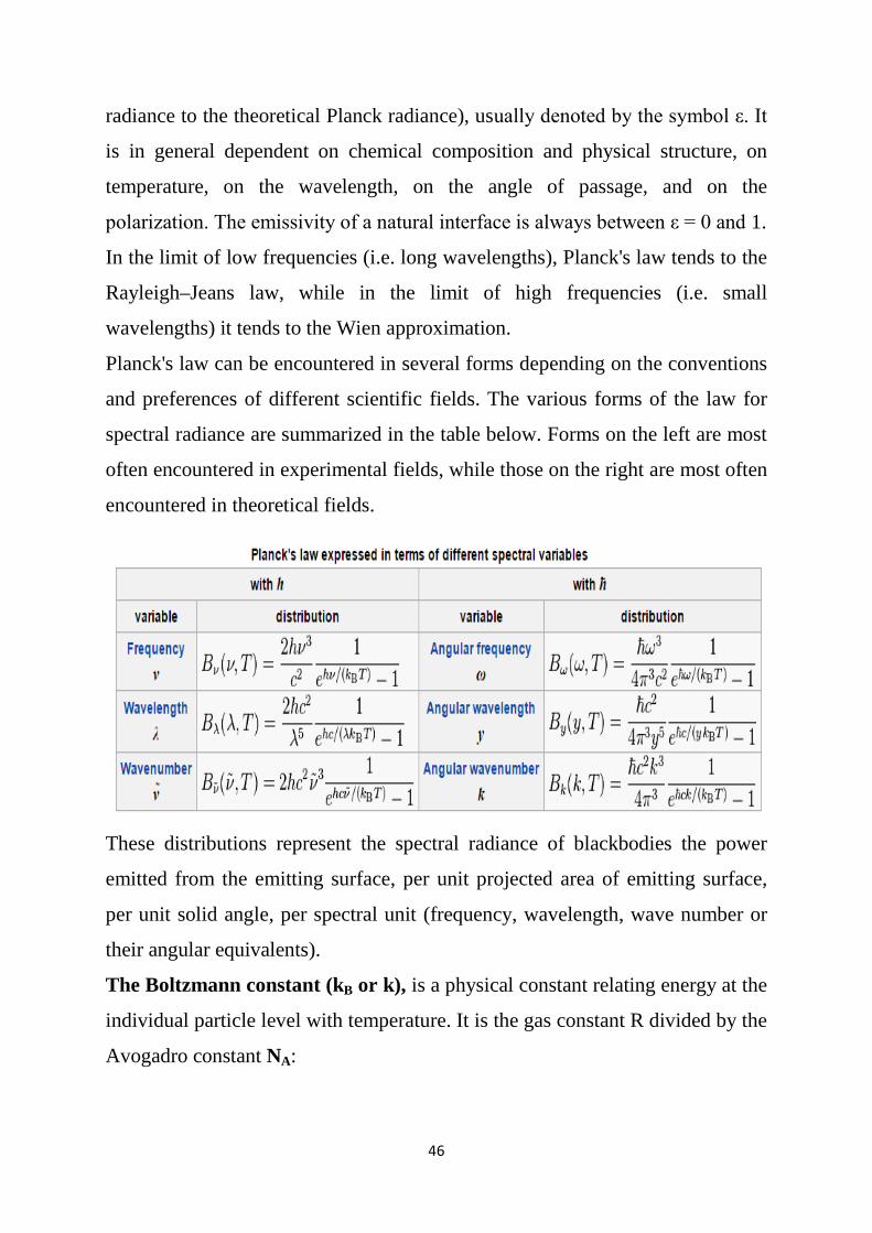
Planck's law can be encountered in several forms depending on the conventions
and preferences of different scientific fields. The various forms of the law for
spectral radiance are summarized in the table below. Forms on the left are most
often encountered in experimental fields, while those on the right are most often
encountered in theoretical fields.
These distributions represent the spectral radiance of blackbodies the power
emitted from the emitting surface, per unit projected area of emitting surface,
per unit solid angle, per spectral unit (frequency, wavelength, wave number or
their angular equivalents).
The Boltzmann constant (kB or k), is a physical constant relating energy at the
individual particle level with temperature. It is the gas constant R divided by the
Avogadro constant NA:
47
The Boltzmann constant has the dimension energy divided by temperature, the
same as entropy. The accepted value in SI units is 1.38*10−23 J/K.
In chemistry and physics, the Avogadro constant is the number of constituent
particles, usually atoms or molecules, that are contained the amount of
substance given by one mole. Thus, the proportionality factor relates the molar
mass of a compound to the mass of a sample. Avogadro's constant, often
designated with the symbol NA, has the value 6.022×10²³ mol−1 in the
International System of Units (SI).
Solid angle (symbol: Ω): is the two-dimensional angle in three-dimensional
space that an object subtends at a point. It is a measure of how large the object
appears to an observer looking from that point. In the International System of
Units (SI), a solid angle is expressed in a dimensionless unit called a steradian
(symbol: sr).
The steradian (symbol: sr): or square radian is the SI unit of solid angle. It is
used in three-dimensional geometry, and is analogous to the radian that
quantifies planar angles.
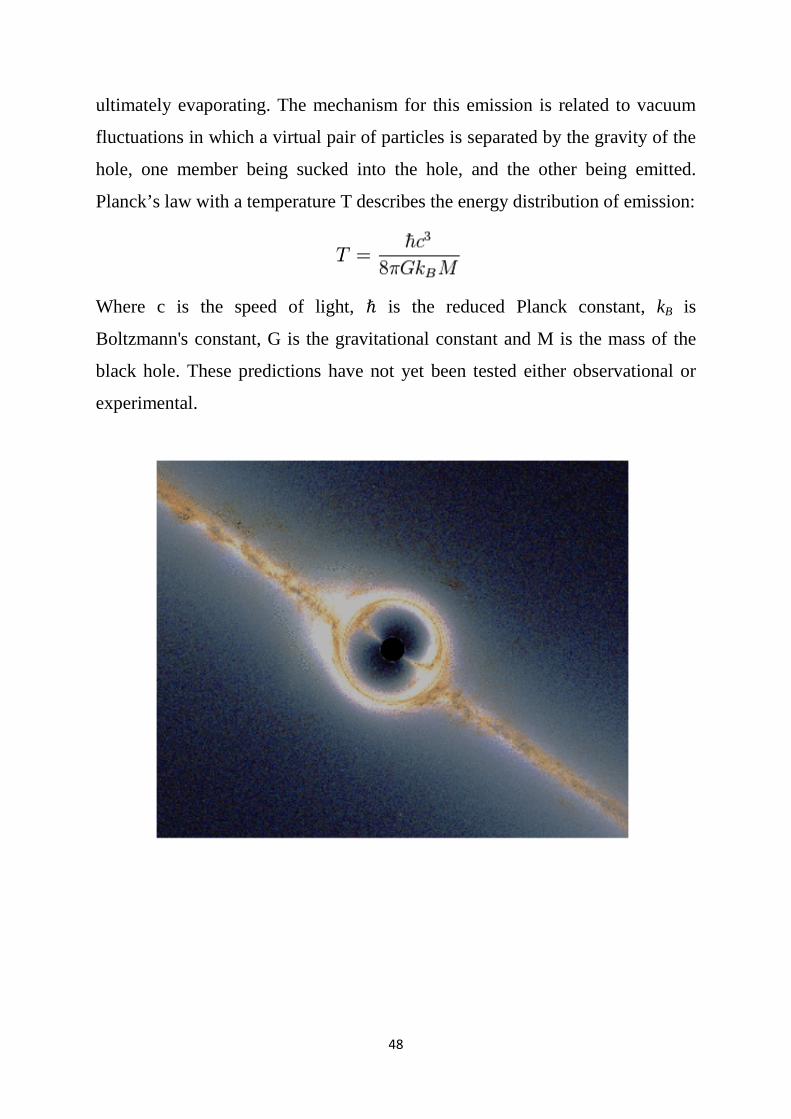
Black holes
A black hole is a region of space-time from which nothing escapes. Around a
black hole there is a mathematically defined surface called an event horizon that
marks the point of no return. It’s called "black" because it absorbs all the light
that hits the horizon, reflecting nothing, making it almost an ideal black body
(radiation with a wavelength equal to or larger than the radius of the hole may
not be absorbed, so black holes are not perfect black bodies).
Physicists believe that to an outside observer, black holes have a non-zero
temperature and emit radiation with a nearly perfect blackbody spectrum,
48
ultimately evaporating. The mechanism for this emission is related to vacuum
fluctuations in which a virtual pair of particles is separated by the gravity of the
hole, one member being sucked into the hole, and the other being emitted.
Planck’s law with a temperature T describes the energy distribution of emission:
Where c is the speed of light, ℏ is the reduced Planck constant, kB is
Boltzmann's constant, G is the gravitational constant and M is the mass of the
black hole. These predictions have not yet been tested either observational or
experimental.
49
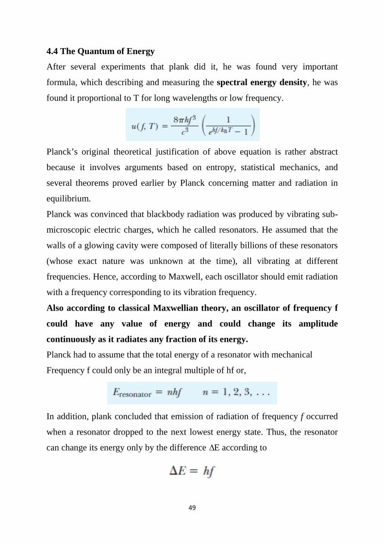
4.4 The Quantum of Energy
After several experiments that plank did it, he was found very important
formula, which describing and measuring the spectral energy density, he was
found it proportional to T for long wavelengths or low frequency.
Planck’s original theoretical justification of above equation is rather abstract
because it involves arguments based on entropy, statistical mechanics, and
several theorems proved earlier by Planck concerning matter and radiation in
equilibrium.
Planck was convinced that blackbody radiation was produced by vibrating sub-
microscopic electric charges, which he called resonators. He assumed that the
walls of a glowing cavity were composed of literally billions of these resonators
(whose exact nature was unknown at the time), all vibrating at different
frequencies. Hence, according to Maxwell, each oscillator should emit radiation
with a frequency corresponding to its vibration frequency.
Also according to classical Maxwellian theory, an oscillator of frequency f
could have any value of energy and could change its amplitude
continuously as it radiates any fraction of its energy.
Planck had to assume that the total energy of a resonator with mechanical
Frequency f could only be an integral multiple of hf or,
In addition, plank concluded that emission of radiation of frequency f occurred
when a resonator dropped to the next lowest energy state. Thus, the resonator
can change its energy only by the difference ∆E according to
50
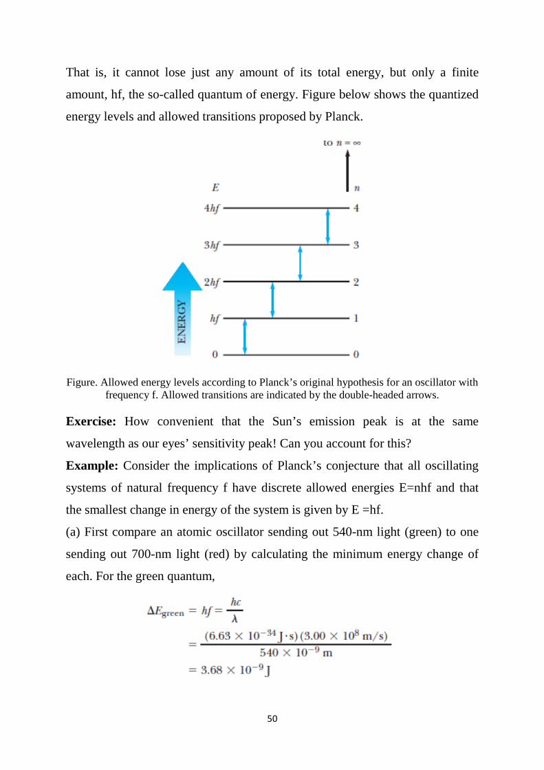
That is, it cannot lose just any amount of its total energy, but only a finite
amount, hf, the so-called quantum of energy. Figure below shows the quantized
energy levels and allowed transitions proposed by Planck.
Figure. Allowed energy levels according to Planck’s original hypothesis for an oscillator with
frequency f. Allowed transitions are indicated by the double-headed arrows.
Exercise: How convenient that the Sun’s emission peak is at the same
wavelength as our eyes’ sensitivity peak! Can you account for this?
Example: Consider the implications of Planck’s conjecture that all oscillating
systems of natural frequency f have discrete allowed energies E=nhf and that
the smallest change in energy of the system is given by E =hf.
(a) First compare an atomic oscillator sending out 540-nm light (green) to one
sending out 700-nm light (red) by calculating the minimum energy change of
each. For the green quantum,
51
Actually, the joule is much too large a unit of energy for describing atomic
processes; so that the minimum energy change of an atomic oscillator sending
out green light is;
For the red quantum the minimum energy change is
(b) Now consider a pendulum undergoing small oscillations with length L=1 m.
According to classical theory, if air friction is present, the amplitude of swing
and consequently the energy decrease continuously with time. Actually, all
systems vibrating with frequency f are quantized and lose energy in discrete
packets or quanta, hf.
An energy change of one quantum corresponds to
Exercise: Calculate the quantum number, n, for this pendulum with E = 1.5x
10-2 J. Answer 4.6x1031
Exercise: An object of mass m on a spring of stiffness k oscillates with
amplitude A about its equilibrium position. Suppose that m=300 g, k=10 N/m,
and A=10 cm. (a) Find the total energy. (b) Find the mechanical frequency of
vibration of the mass. (c) Calculate the change in amplitude when the system
loses one quantum of energy.
52
CHAPTER 5
Structure of the Atom 5.1 The Atomic Nature of Matter
The discovery and proof of the graininess of the world seem especially
fascinating for two reasons. First, because of the size of individual atoms,
measurements of atomic properties are usually indirect and necessarily involve
clever manipulations of large-scale measurements to infer properties of
microscopic particles. Second, the historical evolution of ideas about atomicity
shows clearly the real way in which science progresses. This progression is
often nonlinear and involves an interdependence of physics, chemistry, and
mathematics, and the convergence of many different lines of investigation.
Democritus and Leucippus, who speculated that the unchanging substratum of
the world was atoms in motion; the debonair French chemist Lavoisier and his
wife, who established the conservation of matter in many careful chemical
experiments; Dalton, who perceived the atomicity of nature in the law of
multiple proportions of compounds; Avogadro, who in a most obscure and
little-appreciated paper, postulated that all pure gases at the same temperature
and pressure have the same number of molecules per unit volume; and
Maxwell, who showed with his molecular-kinetic theory of gases how
macroscopic quantities, such as pressure and temperature, could be derived
from averages over distributions of molecular properties. The list could run on
and who carried on very important theoretical and experimental work
concerning Brownian motion, the zigzag movement of small-suspended
particles caused by molecular impacts.
53
5.2 The Composition of Atoms
The question, “If matter is primarily composed of atoms, what are atoms
composed of? Again, we can point to some primary discoveries that showed
that atoms are composed of light, negatively charged particles orbiting a heavy,
positively charged nucleus. These were;
The discovery of the law of electrolysis in 1833 by Michael Faraday,
through careful experimental work on electrolysis, Faraday showed that
the mass of an element liberated at an electrode is directly proportional to
the charge transferred and to the atomic weight of the liberated material
but is inversely proportional to the valence of the freed material.
The identification of cathode rays as electrons and the measurement of
the charge-tomass ratio (e/me) of these particles by Joseph John ( J. J.)
Thomson in 1897. Thomson measured the properties of negative particles
emitted from different metals and found that the value of e/me was
always the same. He thus concluded that the electron is a constituent of
all matter!
The precise measurement of the electronic charge (e) by Robert Millikan
in 1909. By combining his result for (e) with Thomson’s e/me value,
Millikan showed unequivocally that particles about 1000 times less
massive than the hydrogen atom exist.
The establishment of the nuclear model of the atom by Ernest Rutherford
and co-workers Hans Geiger and Ernest Marsden in 1913. By scattering
fast-moving particles (charged nuclei of helium atoms emitted
spontaneously in radioactive decay processes) from metal foil targets,
Rutherford established that atoms consist of a compact positively charged
nucleus (diameter=10-14 m) surrounded by a swarm of orbiting electrons
(electron cloud diameter=10-10 m).
54
Let us describe these developments in more detail. We start with a brief
example of Faraday’s experiments, in particular the electrolysis of molten
common salt (NaCl). Faraday found that if 96,500 C of charge (1 faraday) is
passed through such a molten solution, 23.0 g of Na will deposit on the
cathode and 35.5 g of chlorine gas will bubble off the anode. In this case,
exactly 1-gram atomic weight or mole of each element is released because
both are mono-valent. For divalent and trivalent elements, exactly and 1 of a
mole, respectively, would be released. As expected, doubling the quantity of
charge passed doubles the mass of the neutral element liberated. Faraday’s
results may be given in equation form as;
Where m is the mass of the liberated substance in grams, q is the total charge
Passed in coulombs, the molar mass is in grams, and the valence is
dimensionless.
Example; the Electrolysis of BaCl2
How many grams of barium and chlorine will you get if you pass a current
of 10.0 A through molten BaCl2 for 1 h? Barium has a molar weight of 137 g
and a valence of 2. Chlorine has a molar weight of 35.5 g and a valence of 1.
Solution, using equation above and q? It, where I is the current and t is the
time, we have,
Figure below shows the original vacuum tube used by Thomson in his e/me
experiments. The various parts of the Thomson apparatus for easy reference.
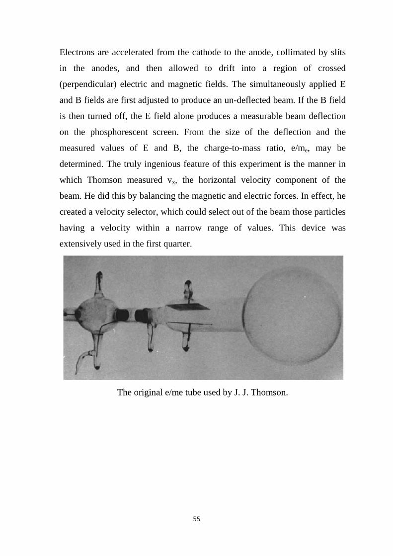
55
Electrons are accelerated from the cathode to the anode, collimated by slits
in the anodes, and then allowed to drift into a region of crossed
(perpendicular) electric and magnetic fields. The simultaneously applied E
and B fields are first adjusted to produce an un-deflected beam. If the B field
is then turned off, the E field alone produces a measurable beam deflection
on the phosphorescent screen. From the size of the deflection and the
measured values of E and B, the charge-to-mass ratio, e/me, may be
determined. The truly ingenious feature of this experiment is the manner in
which Thomson measured vx, the horizontal velocity component of the
beam. He did this by balancing the magnetic and electric forces. In effect, he
created a velocity selector, which could select out of the beam those particles
having a velocity within a narrow range of values. This device was
extensively used in the first quarter.
The original e/me tube used by J. J. Thomson.
56
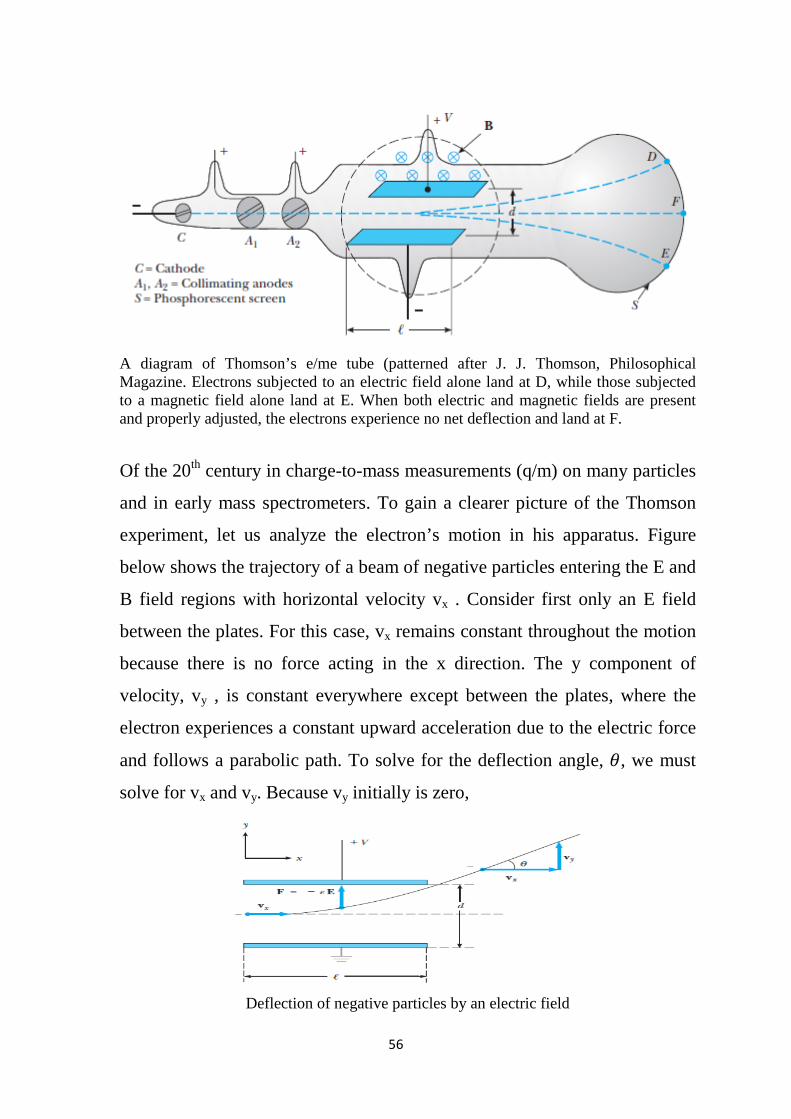
A diagram of Thomson’s e/me tube (patterned after J. J. Thomson, Philosophical Magazine. Electrons subjected to an electric field alone land at D, while those subjected to a magnetic field alone land at E. When both electric and magnetic fields are present and properly adjusted, the electrons experience no net deflection and land at F.
Of the 20th century in charge-to-mass measurements (q/m) on many particles
and in early mass spectrometers. To gain a clearer picture of the Thomson
experiment, let us analyze the electron’s motion in his apparatus. Figure
below shows the trajectory of a beam of negative particles entering the E and
B field regions with horizontal velocity vx . Consider first only an E field
between the plates. For this case, vx remains constant throughout the motion
because there is no force acting in the x direction. The y component of
velocity, vy , is constant everywhere except between the plates, where the
electron experiences a constant upward acceleration due to the electric force
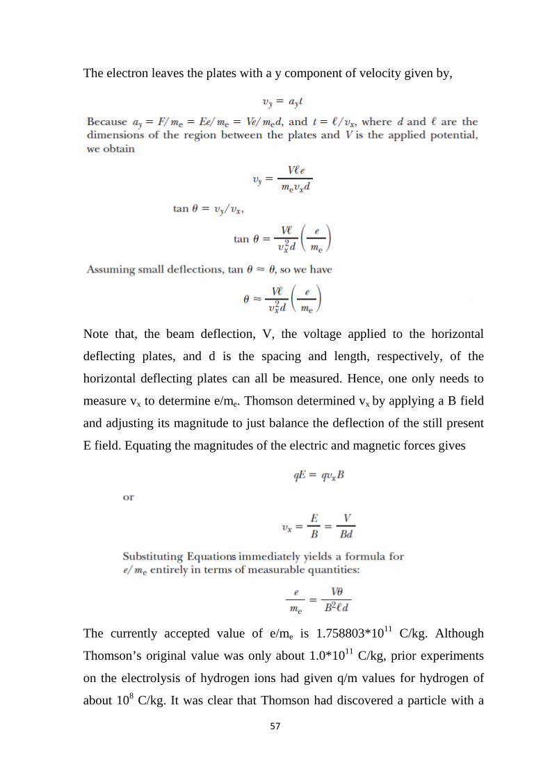
and follows a parabolic path. To solve for the deflection angle, 𝜃𝜃, we must
solve for vx and vy. Because vy initially is zero,
Deflection of negative particles by an electric field
57
The electron leaves the plates with a y component of velocity given by,
Note that, the beam deflection, V, the voltage applied to the horizontal
deflecting plates, and d is the spacing and length, respectively, of the
horizontal deflecting plates can all be measured. Hence, one only needs to
measure vx to determine e/me. Thomson determined vx by applying a B field
and adjusting its magnitude to just balance the deflection of the still present
E field. Equating the magnitudes of the electric and magnetic forces gives
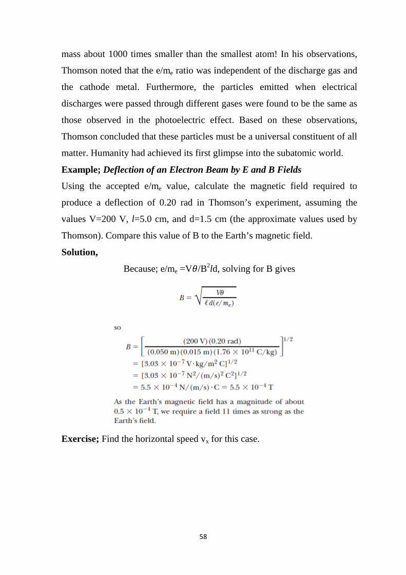
The currently accepted value of e/me is 1.758803*1011 C/kg. Although
Thomson’s original value was only about 1.0*1011 C/kg, prior experiments
on the electrolysis of hydrogen ions had given q/m values for hydrogen of
about 108 C/kg. It was clear that Thomson had discovered a particle with a
58
mass about 1000 times smaller than the smallest atom! In his observations,
Thomson noted that the e/me ratio was independent of the discharge gas and
the cathode metal. Furthermore, the particles emitted when electrical
discharges were passed through different gases were found to be the same as
those observed in the photoelectric effect. Based on these observations,
Thomson concluded that these particles must be a universal constituent of all
matter. Humanity had achieved its first glimpse into the subatomic world.
Example; Deflection of an Electron Beam by E and B Fields
Using the accepted e/me value, calculate the magnetic field required to
produce a deflection of 0.20 rad in Thomson’s experiment, assuming the
values V=200 V, l=5.0 cm, and d=1.5 cm (the approximate values used by
Thomson). Compare this value of B to the Earth’s magnetic field.
Solution,
Because; e/me =V𝜃𝜃/B2ld, solving for B gives
Exercise; Find the horizontal speed vx for this case.
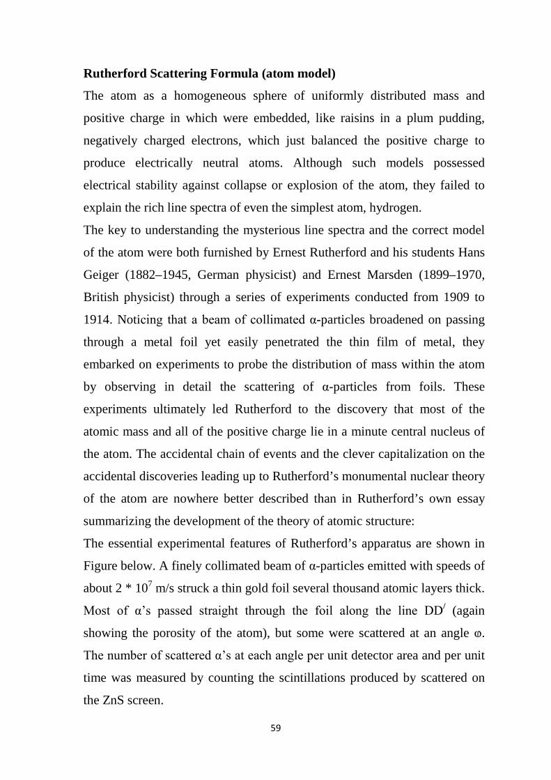
59
Rutherford Scattering Formula (atom model)
The atom as a homogeneous sphere of uniformly distributed mass and
positive charge in which were embedded, like raisins in a plum pudding,
negatively charged electrons, which just balanced the positive charge to
produce electrically neutral atoms. Although such models possessed
electrical stability against collapse or explosion of the atom, they failed to
explain the rich line spectra of even the simplest atom, hydrogen.
The key to understanding the mysterious line spectra and the correct model
of the atom were both furnished by Ernest Rutherford and his students Hans
Geiger (1882–1945, German physicist) and Ernest Marsden (1899–1970,
British physicist) through a series of experiments conducted from 1909 to
1914. Noticing that a beam of collimated α-particles broadened on passing
through a metal foil yet easily penetrated the thin film of metal, they
embarked on experiments to probe the distribution of mass within the atom
by observing in detail the scattering of α-particles from foils. These
experiments ultimately led Rutherford to the discovery that most of the
atomic mass and all of the positive charge lie in a minute central nucleus of
the atom. The accidental chain of events and the clever capitalization on the
accidental discoveries leading up to Rutherford’s monumental nuclear theory
of the atom are nowhere better described than in Rutherford’s own essay
summarizing the development of the theory of atomic structure:
The essential experimental features of Rutherford’s apparatus are shown in
Figure below. A finely collimated beam of α-particles emitted with speeds of
about 2 * 107 m/s struck a thin gold foil several thousand atomic layers thick.
Most of α’s passed straight through the foil along the line DD/ (again
showing the porosity of the atom), but some were scattered at an angle ⱷ.
The number of scattered α’s at each angle per unit detector area and per unit
time was measured by counting the scintillations produced by scattered on
the ZnS screen.
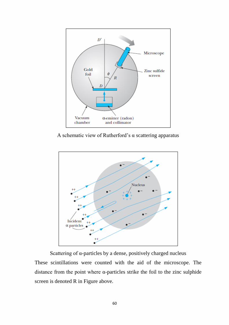
60
A schematic view of Rutherford’s α scattering apparatus
Scattering of α-particles by a dense, positively charged nucleus
These scintillations were counted with the aid of the microscope. The
distance from the point where α-particles strike the foil to the zinc sulphide
screen is denoted R in Figure above.
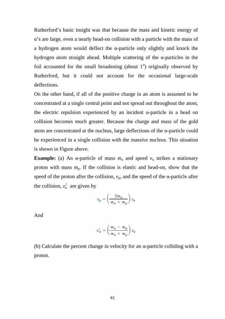
61
Rutherford’s basic insight was that because the mass and kinetic energy of
α’s are large, even a nearly head-on collision with a particle with the mass of
a hydrogen atom would deflect the α-particle only slightly and knock the
hydrogen atom straight ahead. Multiple scattering of the α-particles in the
foil accounted for the small broadening (about 1o) originally observed by
Rutherford, but it could not account for the occasional large-scale
deflections.
On the other hand, if all of the positive charge in an atom is assumed to be
concentrated at a single central point and not spread out throughout the atom,
the electric repulsion experienced by an incident α-particle in a head on
collision becomes much greater. Because the charge and mass of the gold
atom are concentrated at the nucleus, large deflections of the α-particle could
be experienced in a single collision with the massive nucleus. This situation
is shown in Figure above.
Example: (a) An α-particle of mass mα and speed vα strikes a stationary
proton with mass mp. If the collision is elastic and head-on, show that the
speed of the proton after the collision, vp, and the speed of the α-particle after
the collision, 𝑣𝑣𝛼𝛼/ are given by
And
(b) Calculate the percent change in velocity for an α-particle colliding with a
proton.
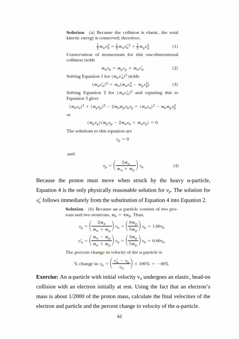
62
Because the proton must move when struck by the heavy α-particle,
Equation 4 is the only physically reasonable solution for vp. The solution for
𝑣𝑣𝛼𝛼/ follows immediately from the substitution of Equation 4 into Equation 2.
Exercise: An α-particle with initial velocity vα undergoes an elastic, head-on
collision with an electron initially at rest. Using the fact that an electron’s
mass is about 1/2000 of the proton mass, calculate the final velocities of the
electron and particle and the percent change in velocity of the α-particle.
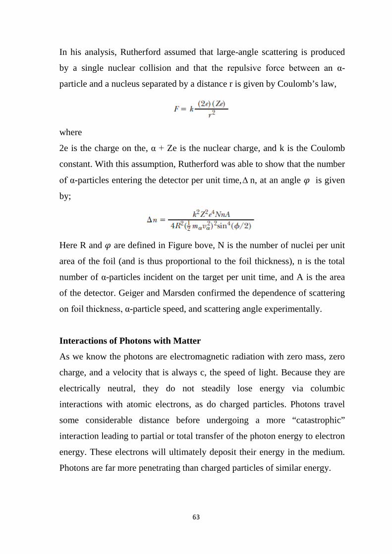
63
In his analysis, Rutherford assumed that large-angle scattering is produced
by a single nuclear collision and that the repulsive force between an α-
particle and a nucleus separated by a distance r is given by Coulomb’s law,
where
2e is the charge on the, α + Ze is the nuclear charge, and k is the Coulomb
constant. With this assumption, Rutherford was able to show that the number
of α-particles entering the detector per unit time, ∆ n, at an angle 𝜑𝜑 is given
by;
Here R and 𝜑𝜑 are defined in Figure bove, N is the number of nuclei per unit
area of the foil (and is thus proportional to the foil thickness), n is the total
number of α-particles incident on the target per unit time, and A is the area
of the detector. Geiger and Marsden confirmed the dependence of scattering
on foil thickness, α-particle speed, and scattering angle experimentally.
Interactions of Photons with Matter
As we know the photons are electromagnetic radiation with zero mass, zero
charge, and a velocity that is always c, the speed of light. Because they are
electrically neutral, they do not steadily lose energy via columbic
interactions with atomic electrons, as do charged particles. Photons travel
some considerable distance before undergoing a more “catastrophic”
interaction leading to partial or total transfer of the photon energy to electron
energy. These electrons will ultimately deposit their energy in the medium.
Photons are far more penetrating than charged particles of similar energy.
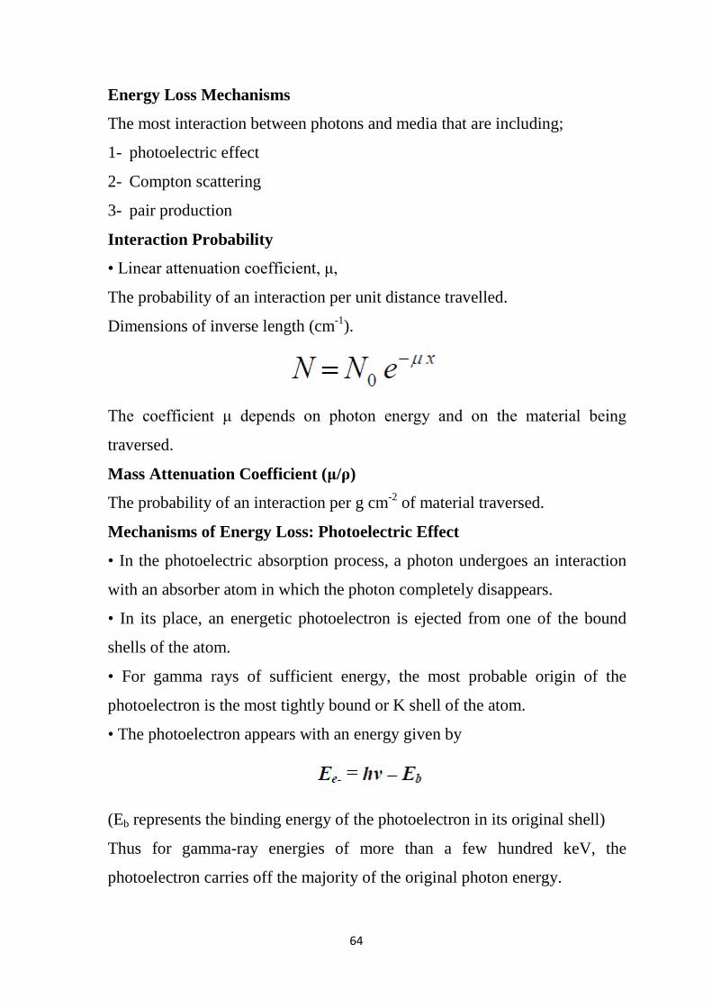
64
Energy Loss Mechanisms
The most interaction between photons and media that are including;
1- photoelectric effect
2- Compton scattering
3- pair production
Interaction Probability
• Linear attenuation coefficient, μ,
The probability of an interaction per unit distance travelled.
Dimensions of inverse length (cm-1).
The coefficient μ depends on photon energy and on the material being
traversed.
Mass Attenuation Coefficient (μ/ρ)
The probability of an interaction per g cm-2 of material traversed.
Mechanisms of Energy Loss: Photoelectric Effect
• In the photoelectric absorption process, a photon undergoes an interaction
with an absorber atom in which the photon completely disappears.
• In its place, an energetic photoelectron is ejected from one of the bound
shells of the atom.
• For gamma rays of sufficient energy, the most probable origin of the
photoelectron is the most tightly bound or K shell of the atom.
• The photoelectron appears with an energy given by
(Eb represents the binding energy of the photoelectron in its original shell)
Thus for gamma-ray energies of more than a few hundred keV, the
photoelectron carries off the majority of the original photon energy.
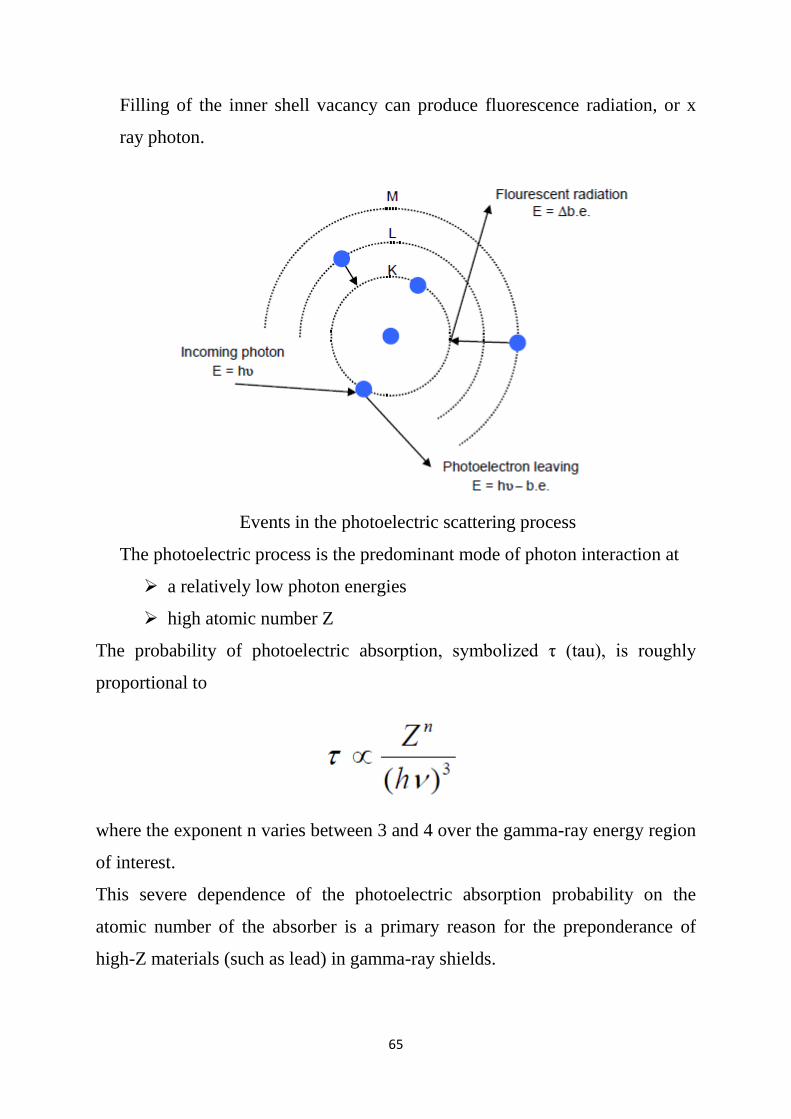
65
Filling of the inner shell vacancy can produce fluorescence radiation, or x
ray photon.
Events in the photoelectric scattering process
The photoelectric process is the predominant mode of photon interaction at
a relatively low photon energies
high atomic number Z
The probability of photoelectric absorption, symbolized τ (tau), is roughly
proportional to
where the exponent n varies between 3 and 4 over the gamma-ray energy region
of interest.
This severe dependence of the photoelectric absorption probability on the
atomic number of the absorber is a primary reason for the preponderance of
high-Z materials (such as lead) in gamma-ray shields.
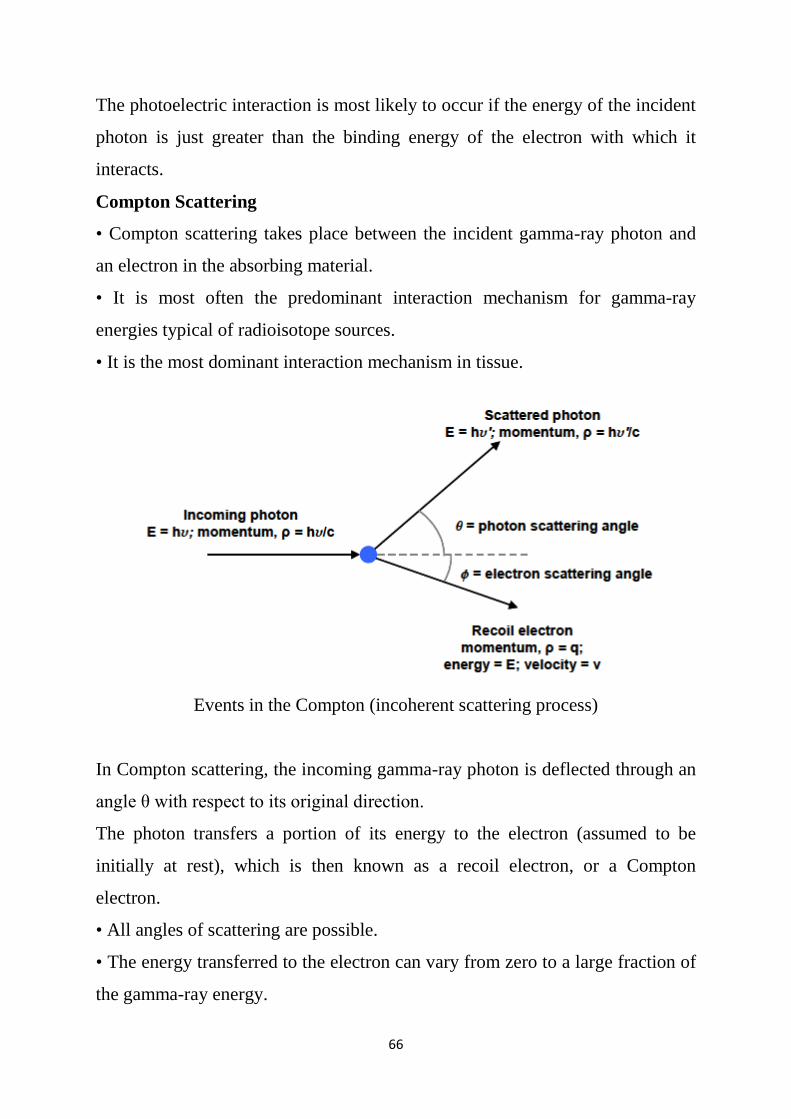
66
The photoelectric interaction is most likely to occur if the energy of the incident
photon is just greater than the binding energy of the electron with which it
interacts.
Compton Scattering
• Compton scattering takes place between the incident gamma-ray photon and
an electron in the absorbing material.
• It is most often the predominant interaction mechanism for gamma-ray
energies typical of radioisotope sources.
• It is the most dominant interaction mechanism in tissue.
Events in the Compton (incoherent scattering process)
In Compton scattering, the incoming gamma-ray photon is deflected through an
angle θ with respect to its original direction.
The photon transfers a portion of its energy to the electron (assumed to be
initially at rest), which is then known as a recoil electron, or a Compton
electron.
• All angles of scattering are possible.
• The energy transferred to the electron can vary from zero to a large fraction of
the gamma-ray energy.
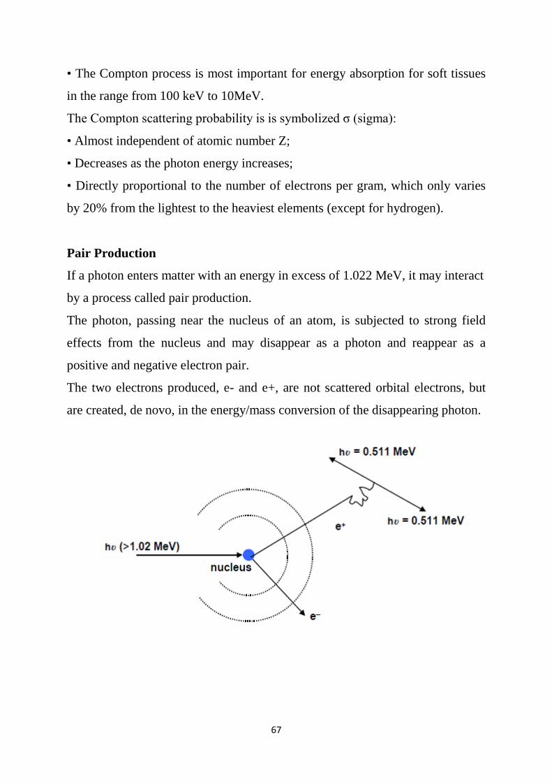
67
• The Compton process is most important for energy absorption for soft tissues
in the range from 100 keV to 10MeV.
The Compton scattering probability is is symbolized σ (sigma):
• Almost independent of atomic number Z;
• Decreases as the photon energy increases;
• Directly proportional to the number of electrons per gram, which only varies
by 20% from the lightest to the heaviest elements (except for hydrogen).
Pair Production
If a photon enters matter with an energy in excess of 1.022 MeV, it may interact
by a process called pair production.
The photon, passing near the nucleus of an atom, is subjected to strong field
effects from the nucleus and may disappear as a photon and reappear as a
positive and negative electron pair.
The two electrons produced, e- and e+, are not scattered orbital electrons, but
are created, de novo, in the energy/mass conversion of the disappearing photon.
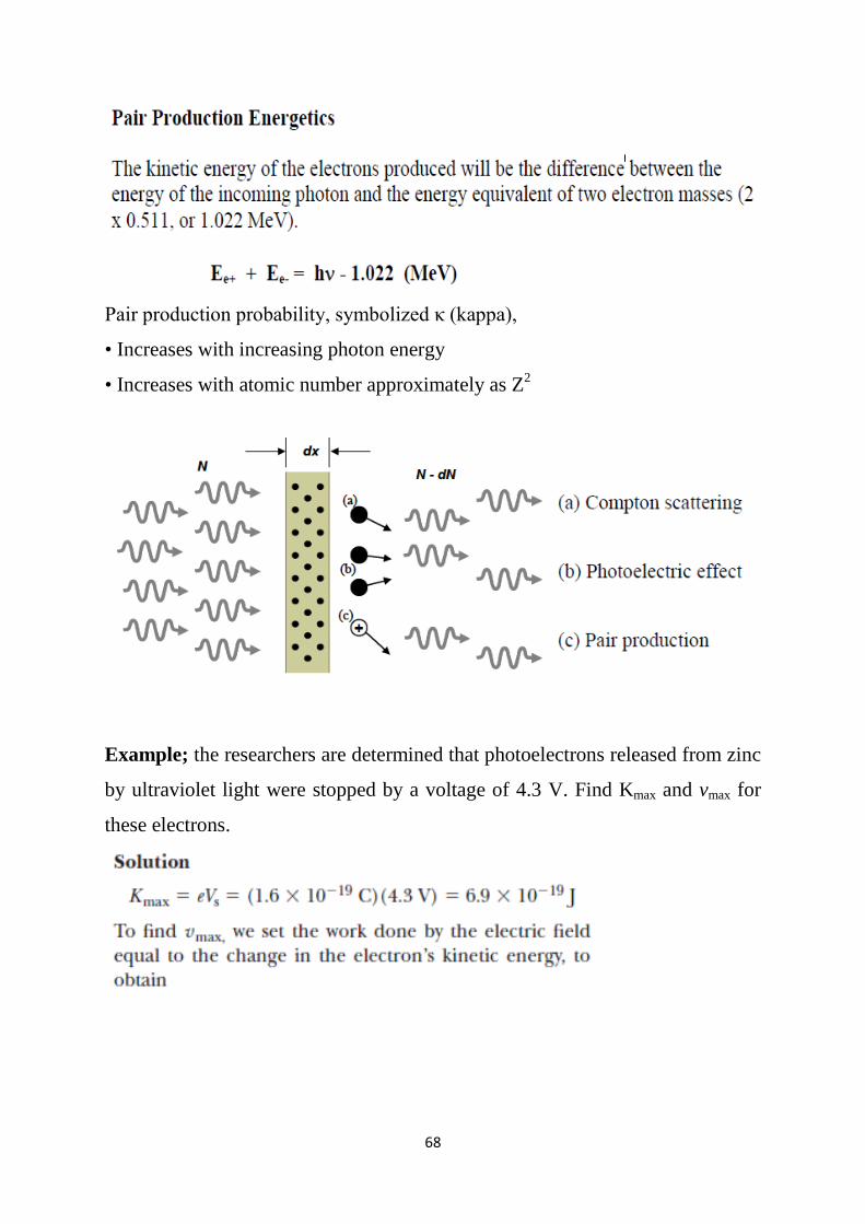
68
Pair production probability, symbolized κ (kappa),
• Increases with increasing photon energy
• Increases with atomic number approximately as Z2
Example; the researchers are determined that photoelectrons released from zinc
by ultraviolet light were stopped by a voltage of 4.3 V. Find Kmax and vmax for
these electrons.
69
Example; suppose that light of total intensity 1.0 uW/cm2 falls on a clean iron
sample 1.0 cm2 in area. Assume that the iron sample reflects 96% of the light
and that only 3.0% of the absorbed energy lies in the violet region of the
spectrum above the threshold frequency.
a- What intensity is actually available for the photoelectric effect?
b- Assuming that all the photons in the violet region have an effective
wavelength of 250 nm, how many electrons will be emitted per second
c- Calculate the current in the phototube in amperes.
a- Because only 4.0% of the incident energy is absorbed, and only 3.0% of this
energy is able to produce photoelectrons, the intensity available is
b-
c-
A sensitive electrometer is needed to detect this small current.
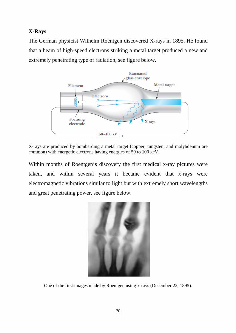
70
X-Rays
The German physicist Wilhelm Roentgen discovered X-rays in 1895. He found
that a beam of high-speed electrons striking a metal target produced a new and
extremely penetrating type of radiation, see figure below.
X-rays are produced by bombarding a metal target (copper, tungsten, and molybdenum are common) with energetic electrons having energies of 50 to 100 keV. Within months of Roentgen’s discovery the first medical x-ray pictures were
taken, and within several years it became evident that x-rays were
electromagnetic vibrations similar to light but with extremely short wavelengths
and great penetrating power, see figure below.
One of the first images made by Roentgen using x-rays (December 22, 1895).
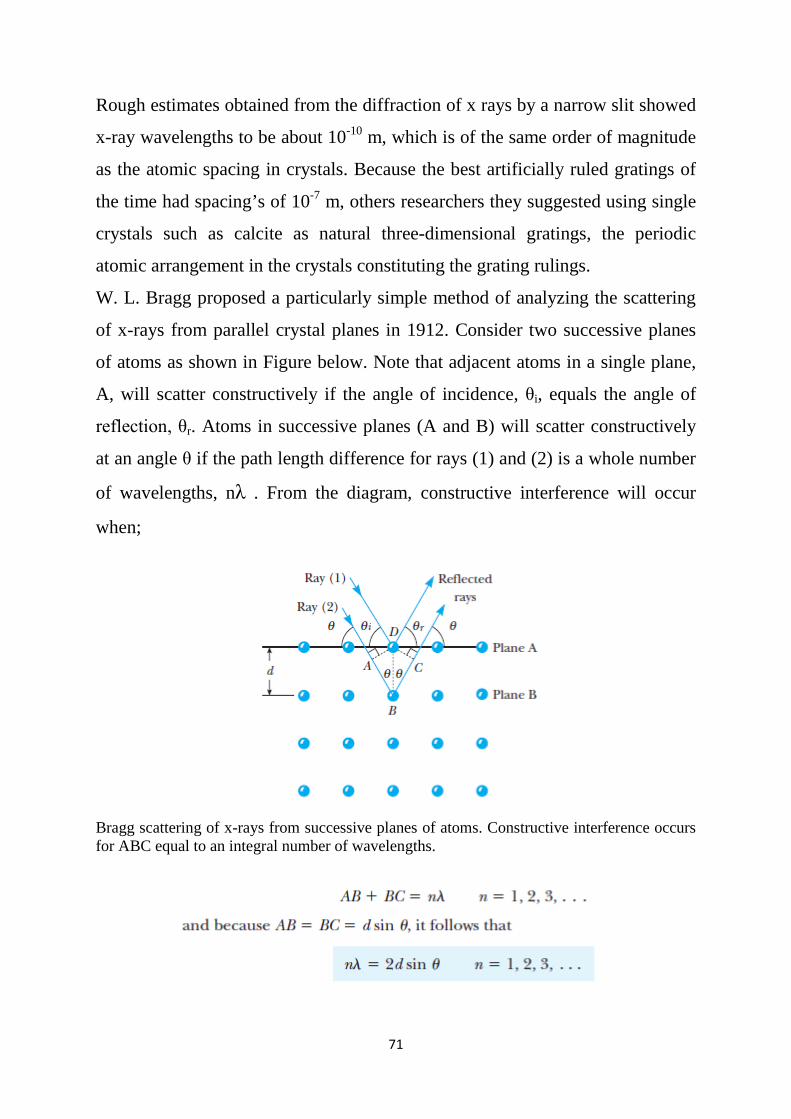
71
Rough estimates obtained from the diffraction of x rays by a narrow slit showed
x-ray wavelengths to be about 10-10 m, which is of the same order of magnitude
as the atomic spacing in crystals. Because the best artificially ruled gratings of
the time had spacing’s of 10-7 m, others researchers they suggested using single
crystals such as calcite as natural three-dimensional gratings, the periodic
atomic arrangement in the crystals constituting the grating rulings.
W. L. Bragg proposed a particularly simple method of analyzing the scattering
of x-rays from parallel crystal planes in 1912. Consider two successive planes
of atoms as shown in Figure below. Note that adjacent atoms in a single plane,
A, will scatter constructively if the angle of incidence, θi, equals the angle of
reflection, θr. Atoms in successive planes (A and B) will scatter constructively
at an angle θ if the path length difference for rays (1) and (2) is a whole number
of wavelengths, nλ . From the diagram, constructive interference will occur
when;
Bragg scattering of x-rays from successive planes of atoms. Constructive interference occurs for ABC equal to an integral number of wavelengths.
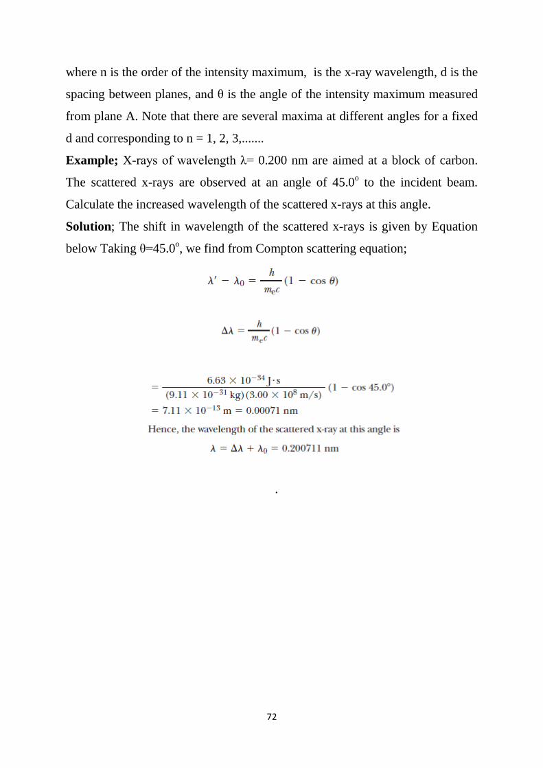
72
where n is the order of the intensity maximum, is the x-ray wavelength, d is the
spacing between planes, and θ is the angle of the intensity maximum measured
from plane A. Note that there are several maxima at different angles for a fixed
d and corresponding to n = 1, 2, 3,.......
Example; X-rays of wavelength λ= 0.200 nm are aimed at a block of carbon.
The scattered x-rays are observed at an angle of 45.0o to the incident beam.
Calculate the increased wavelength of the scattered x-rays at this angle.
Solution; The shift in wavelength of the scattered x-rays is given by Equation
below Taking θ=45.0o, we find from Compton scattering equation;
.