Embed Size (px)
Citation preview
825.116.000 20152015
SYMBOLSSYMBOLS
SMARTDRIVER
SMARTREVOLUTION
SM
AR
TD
RIV
ER
H 6 mH 3 mH 2.5 m H 6 mH 6 m
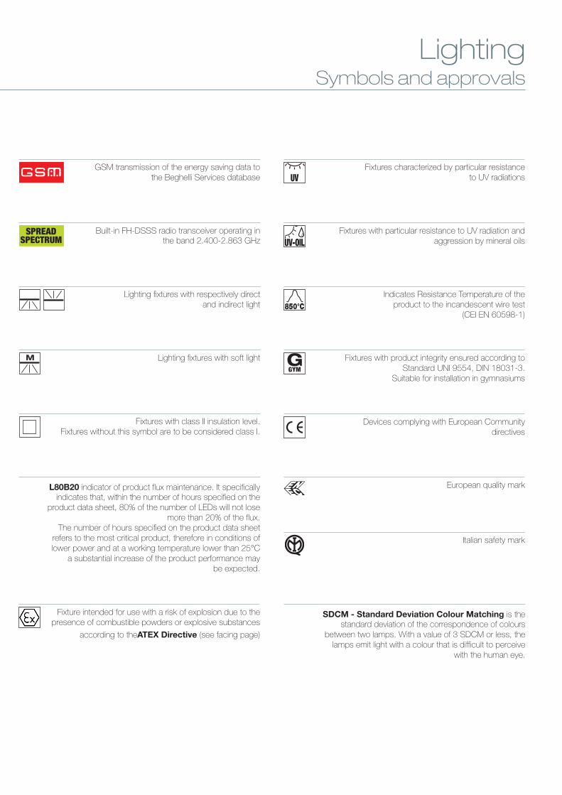
Devices complying with European Communitydirectives
Fixture with a photosensor allowing activation ofthe fixture in SA mode automatically as soon as
the threshold of environment light is lowered
12 HOURSRECHARGE
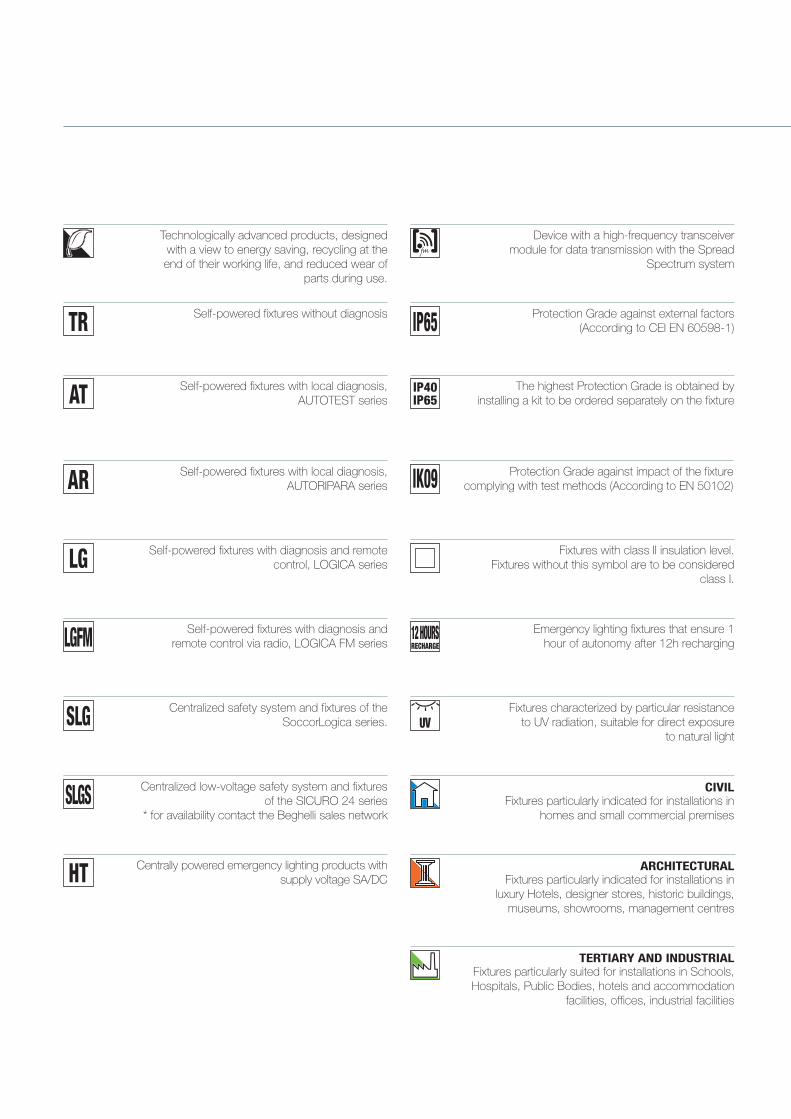
Emergency lighting fixtures that ensure 1hour of autonomy after 12h recharging
Fixture suitable for safety signs according to UNI EN 1838.DV (visibility distance): see dimensions table in the
TECHNICAL DATA SHEETS.
Fixtures with product integrity ensured according toStandard UNI 9554, DIN 18031-3.
Suitable for installation in gymnasiums
GGYM
Technologically advanced products, designedwith a view to energy saving, recycling at theend of their working life, and reduced wear of
parts during use.
Emergency LightingSymbols and approvals
IP65
Series of emergency fixtures with possibilityof excluding the emergency by remote
control (Rest-Mode)
RM Version
Emergency fixtures for non permanentlighting
SE Version
Emergency fixtures for permanentlighting
SA Version
Fixtures with reduced permanent lighting(Public Performance)
PS Version
Fixtures with class II insulation level.Fixtures without this symbol are to be considered
class I.
Protection Grade against external factors(According to CEI EN 60598-1)
Self-powered fixtures with diagnosis andremote control via radio, LOGICA FM series
Self-powered fixtures with diagnosis and remotecontrol, LOGICA series
Centralized safety system and fixtures of theSoccorLogica series.
AT Self-powered fixtures with local diagnosis,AUTOTEST series
AR Self-powered fixtures with local diagnosis,AUTORIPARA series
TR Self-powered fixtures without diagnosis
LG
LGFM
Centralized low-voltage safety system and fixturesof the SICURO 24 series
* for availability contact the Beghelli sales network SLGS
SLG
European quality mark
Italian safety mark
Device with a high-frequency transceivermodule for data transmission with the Spread
Spectrum system
HT Centrally powered emergency lighting products withsupply voltage SA/DC
HACCP
Fixtures with absence of potentially contaminatingelements, suitable for use in places subject to
HACCP audit (food supply chain).
Products with extended 4-year guarantee on all parts,battery included. For the application
procedures, see the general terms of sale.
IP40IP65
The highest Protection Grade is obtained byinstalling a kit to be ordered separately on the fixture
Fixtures that ensure precise illumination (Lx) on the worksurface, if mounted as indicated in the icon.
Fixture intended for use with a risk of explosion due to thepresence of combustible powders or explosivesubstances according to the ATEX Directive
Protection Grade against impact of the fixturecomplying with test methods (According to EN 50102)IK09
Fixtures suitable for installation in high-riskareas
Indicates Resistance Temperature of the product tothe incandescent wire test (CEI EN 60598-1)850°C
UVFixtures characterized by particular resistanceto UV radiation, suitable for direct exposure
to natural light
UV-OILFixtures with particular resistance to UV radiation and
aggression by mineral oils
GSM transmission of the energy saving data tothe Beghelli Services database
Built-in FH-DSSS radio transceiver operating inthe band 2.400-2.863 GHz
L80B20 indicator of product flux maintenance. It specificallyindicates that, within the number of hours specified on the product
data sheet, 80% of the number of LEDs will not lose more than 20%of the flux.
The number of hours specified on the product data sheet refers tothe most critical product, therefore in conditions of lower power andat a working temperature lower than 25°C a substantial increase of
the product performance may be expected.
SDCM - Standard Deviation Colour Matching is thestandard deviation of the correspondence of colours
between two lamps. With a value of 3 SDCM or less, thelamps emit light with a colour that is difficult to perceive
with the human eye.
TERTIARY AND INDUSTRIALFixtures particularly suited for installations in Schools,Hospitals, Public Bodies, hotels and accommodation
facilities, offices, industrial facilities
CIVILFixtures particularly indicated for installations in
homes and small commercial premises
ARCHITECTURALFixtures particularly indicated for installations in
luxury Hotels, designer stores, historic buildings,museums, showrooms, management centres
GB int_cop SPSD_01 21/05/15 14:58 Pagina 2
DARKLIGHT
Low luminosity optics Visual comfort is obtainedwith correct lighting design, using fixtures in whichthe control of the luminous flux reduces direct andreflected glare. Beghelli propose 5 classifications oftheir flux-control optics.
Low luminosity optics, less than 200 cd/m² for angles greater than60° longitudinal and transverse, and for radial angles compliant withEN 12464-1 limit 1000cd/m²
Low luminosity optics, less than 500 cd/m² for angles greater than65° longitudinal and transverse, and for radial angles compliant withEN 12464-1 limit 1000cd/m²
Low luminosity optics compliant with standard EN 12464-1 limit1000cd/m²
Low luminosity optics compliant with standard EN 12464-1 limit1500cd/m²
Low luminosity optics compliant with standard EN 12464-1 limit3000cd/m²
DKL3
DKL4
DKL5
DKL2
DKL1
LIGHT SOURCES SUPPLIED WITH BEGHELLI FIXTURES
Beghelli products must be used with light sources complying with the provisions of the mostrecent laws in terms of energy efficiency and environmental impact. When supplied with thelighting fixtures, the proposed lamps supplied comply with the provisions of the respectivelaws (reg 244/09, 245/09 and 1194/2012).
European quality mark
Italian safety mark
GSM transmission of the energy saving data tothe Beghelli Services database
Built-in FH-DSSS radio transceiver operating inthe band 2.400-2.863 GHz
IP65 Fixtures with class II insulation level.Fixtures without this symbol are to be considered class I.
L80B20 indicator of product flux maintenance. It specificallyindicates that, within the number of hours specified on the
product data sheet, 80% of the number of LEDs will not losemore than 20% of the flux.
The number of hours specified on the product data sheetrefers to the most critical product, therefore in conditions oflower power and at a working temperature lower than 25°C
a substantial increase of the product performance maybe expected.
SDCM - Standard Deviation Colour Matching is thestandard deviation of the correspondence of colours
between two lamps. With a value of 3 SDCM or less, thelamps emit light with a colour that is difficult to perceive
with the human eye.
Protection Grade against external factors(According to CEI EN 60598-1)
IK09 Protection Grade against impact of the fixturecomplying with test methods (According to EN 50102)
SmartDriver: Dimmable control gear for LEDsources which has two connectors for as manyoptional devices that modify the characteristicsof the fixture. The first connector is exclusivelyfor connection of the Autodimmer Sensor, thesecond is for a Building Automation Module
chosen from the SmartDriver series. Alternativemodules that can be connected: BuildingAutomation Module, Dali Module - 0/10W,Grande Esco Italia Module, Vision Module.
IP40IP41
Protection Grade against external factors of a part ofthe fixture (housing, optics) (according to
CEI EN 60598-1)
HACCP
Fixtures with absence of potentially contaminatingelements, suitable for use in places subject to HACCP
audit (food supply chain).
Devices complying with European Communitydirectives
Indicates Resistance Temperature of theproduct to the incandescent wire test
(CEI EN 60598-1)850°C
M Lighting fixtures with soft light
Technologically advanced products, designedspecifically with a view to energy saving, recycling at
the end of their working life, and reduced periodic wearof parts during use.
Fixtures with product integrity ensured according toStandard UNI 9554, DIN 18031-3.
Suitable for installation in gymnasiums
GGYM
Fixture intended for use with a risk of explosion due to thepresence of combustible powders or explosive substances
according to theATEX Directive (see facing page)
UVFixtures characterized by particular resistance
to UV radiations
UV-OILFixtures with particular resistance to UV radiation and
aggression by mineral oils
Line of fixtures in sheet steel and toughened glass withhigh characteristics of resistance to external agents
LightingSymbols and approvals
Lighting fixtures with respectively directand indirect light
The light fixtures in the Stella Polare LED line areequipped with particularly performing diffusers and
optics. In a comparison with standard fixtures on themarket, with a greater luminous flux (lumen), BeghelliLuce Utile fixtures ensure up to 20% more illumination
on the work surface (lux).This greater efficiency is expressed in an equivalent
energy saving.
Centralized low-voltage safety system and fixtures ofthe SICURO 24 series
(for availability contact the Beghelli sales network)
SLGS
GB int_cop SPSD_01 21/05/15 14:58 Pagina 4

dghxfgfxg
1
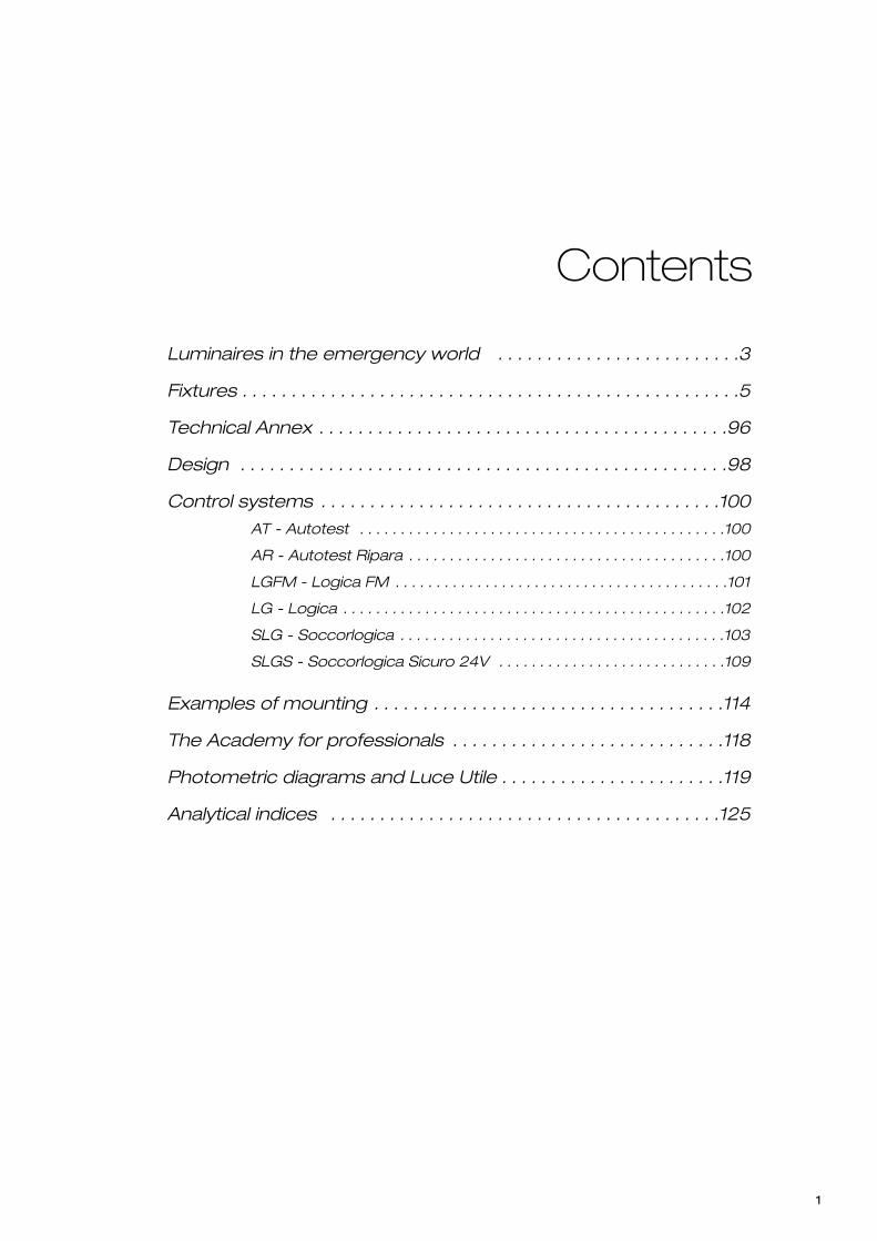
Luminaires in the emergency world . . . . . . . . . . . . . . . . . . . . . . . . .3
Fixtures . . . . . . . . . . . . . . . . . . . . . . . . . . . . . . . . . . . . . . . . . . . . . . . . . . .5
Technical Annex . . . . . . . . . . . . . . . . . . . . . . . . . . . . . . . . . . . . . . . . . .96
Design . . . . . . . . . . . . . . . . . . . . . . . . . . . . . . . . . . . . . . . . . . . . . . . . . .98
Control systems . . . . . . . . . . . . . . . . . . . . . . . . . . . . . . . . . . . . . . . . .100
AT - Autotest . . . . . . . . . . . . . . . . . . . . . . . . . . . . . . . . . . . . . . . . . . . . .100
AR - Autotest Ripara . . . . . . . . . . . . . . . . . . . . . . . . . . . . . . . . . . . . . . .100
LGFM - Logica FM . . . . . . . . . . . . . . . . . . . . . . . . . . . . . . . . . . . . . . . . .101
LG - Logica . . . . . . . . . . . . . . . . . . . . . . . . . . . . . . . . . . . . . . . . . . . . . . .102
SLG - Soccorlogica . . . . . . . . . . . . . . . . . . . . . . . . . . . . . . . . . . . . . . . .103
SLGS - Soccorlogica Sicuro 24V . . . . . . . . . . . . . . . . . . . . . . . . . . . .109
Examples of mounting . . . . . . . . . . . . . . . . . . . . . . . . . . . . . . . . . . . .114
The Academy for professionals . . . . . . . . . . . . . . . . . . . . . . . . . . . .118
Photometric diagrams and Luce Utile . . . . . . . . . . . . . . . . . . . . . . .119
Analytical indices . . . . . . . . . . . . . . . . . . . . . . . . . . . . . . . . . . . . . . . .125
Contents

The highly technological identity and the value of theBeghelli brand are fully expressed in the project for therenewal of emergency light sources. In the Stella Polareproject, the use of high-efficiency LEDs and a calibratedlight beam produces adequate lighting while maintainingvery high energy saving.
The Luce Utile (Useful Light) philosophy springs from the need toobtain an ideal beam of light for emergency lighting that gives themaximum possible light output. The optics have been speciallydesigned to solve lighting problems on the ground with a smallernumber of fixtures, respecting the values envisaged by theregulations in force.
We are proud to present on the market a new concept ofEmergency Lighting that goes beyond the limits of simple productinnovation, taking an impressive leap forward in the sector.We are certain that all experts in the sector - designers, architects,wholesalers and installers - will recognise in “Stella Polare” theinnovative spirit that animates us, and will propose its advantagesto their partners and customers to ensure safety in livingenvironments.
Gian Pietro Beghelli
With “Stella Pollare”, Beghelli takes a decided step forward in theEmergency Lighting sector, in the management of luminous fluxand the “intelligence” of Safety Lighting systems. Professionals inthe sector will have ideal tools at their disposal to lend substanceto the integration of technology and safety procedures, in line withthe spirit with which the joint UNI CEI Work Group, which it is mypleasure to coordinate, drew up the UNI CEI 11222 standard.
Fabio Pedrazzi
LuceUtile ProjectIt does not matter how much light a fixture emits.What makes it important is what its light shows,
transforming it into a useful lighting fixture.All the light outside the controlled beam is just a waste of energy.
3
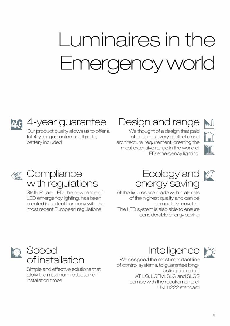
Luminaires in theEmergency world
4-year guaranteeOur product quality allows us to offer afull 4-year guarantee on all parts,battery included
Compliance with regulationsStella Polare LED, the new range ofLED emergency lighting, has beencreated in perfect harmony with themost recent European regulations
Speed of installationSimple and effective solutions thatallow the maximum reduction ofinstallation times
Design and rangeWe thought of a design that paidattention to every aesthetic and
architectural requirement, creating themost extensive range in the world of
LED emergency lighting.
Ecology andenergy saving
All the fixtures are made with materialsof the highest quality and can be
completely recycled.The LED system is also able to ensure
considerable energy saving
IntelligenceWe designed the most important lineof control systems, to guarantee long-
lasting operation. AT, LG, LGFM, SLG and SLGS
comply with the requirements ofUNI 11222 standard

4

LGLOGICA SYSTEM
page 102
AT-ARAUTOTEST-RIPARASELF-POWEREDFIXTURES
page 100
5
Emergency lighting
LUNGLARGALUCE LED - recessedpage 12
LUNGLARGALUCE LED - ceilingpage 18
IP43 IP42
FORMULA 65 LEDpage 26
IP65
GRANLUCE LEDpage 46
IP65
Inverter and LED Module with Inverter
INVERTER LED IP65page 71
IP65
Signs
INDICA LED 30page 82
IP40IP41
LOGICA LEDpage 6
IP65
INVERTER LEDpage 70
IP40
LED MODULE WITH INVERTERpage 56
IP40
INVERTER ECOLED MODULEpage 64
IP40
UP LED EXITpage 90
IP40IP41
INDICA LED 20page 74
IP40IP41
Tracking and control systems: description of Systems and fixture compatibility
LGFMFM LOGICA SYSTEM
page 101
ATAUTOTEST SELF-POWEREDFIXTURES
page 100
SLGSOCCORLOGICASYSTEM
page 103
New
UP LEDpage 34
IP65
UP LED MULTI page 40
IP42
SLGSLOW VOLTAGESOCCORLOGICASYSTEM
page 109
EM
ER
GE
NC
Y F
IXTU
RE
S
1500 lumen New
New
66
77
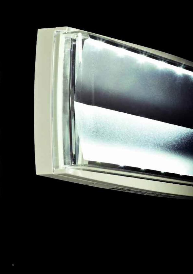
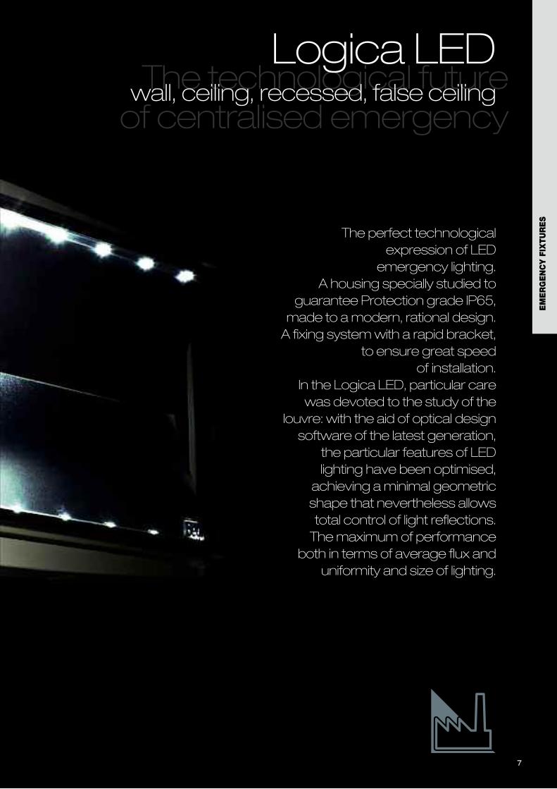
The perfect technologicalexpression of LED emergency lighting.
A housing specially studied toguarantee Protection grade IP65,made to a modern, rational design.A fixing system with a rapid bracket,
to ensure great speed of installation.
In the Logica LED, particular carewas devoted to the study of the
louvre: with the aid of optical designsoftware of the latest generation,
the particular features of LEDlighting have been optimised,achieving a minimal geometricshape that nevertheless allowstotal control of light reflections.The maximum of performance
both in terms of average flux anduniformity and size of lighting.
The technological futureof centralised emergency
Logica LEDwall, ceiling, recessed, false ceiling
EM
ER
GE
NC
Y F
IXTU
RE
S
8
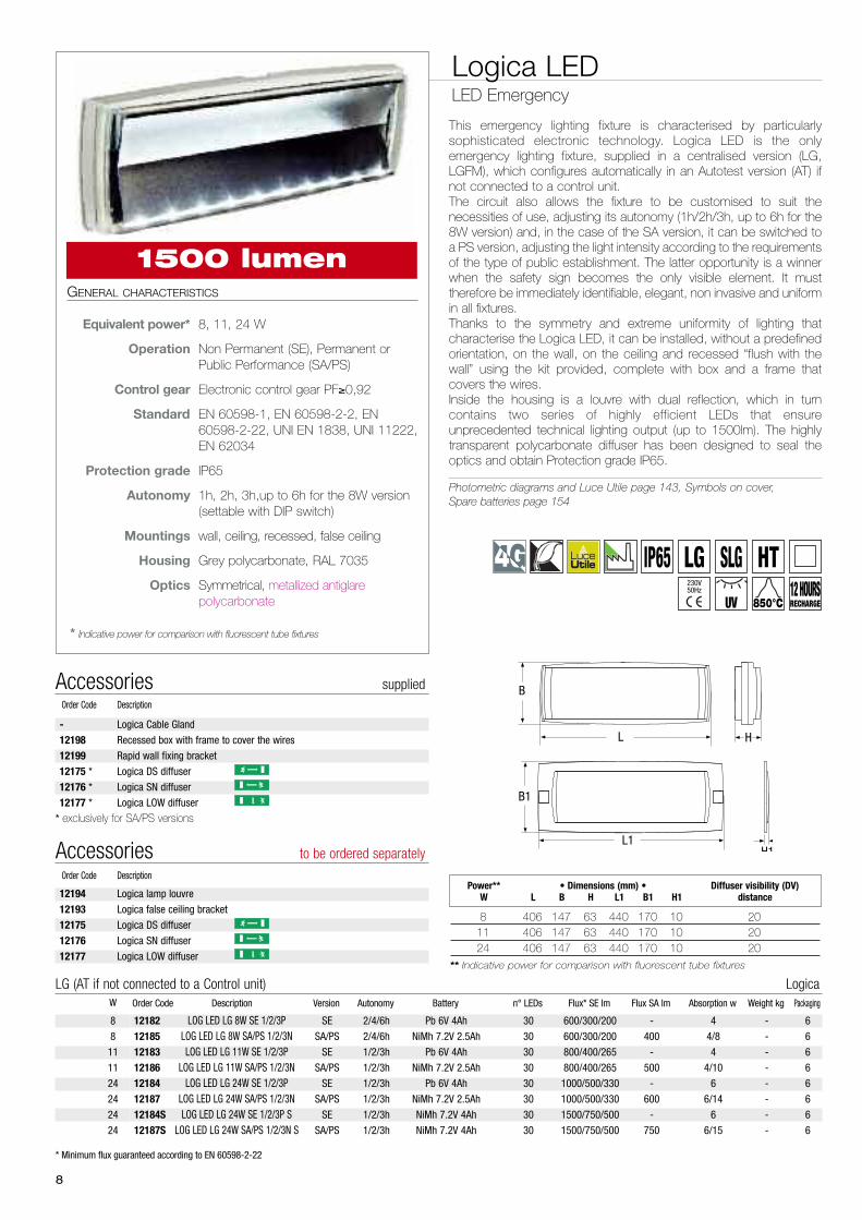
Logica LEDLED Emergency
GENERAL CHARACTERISTICS
Equivalent power* 8, 11, 24 W
Operation Non Permanent (SE), Permanent orPublic Performance (SA/PS)
Control gear Electronic control gear PF≥0,92
Standard EN 60598-1, EN 60598-2-2, EN60598-2-22, UNI EN 1838, UNI 11222,EN 62034
Protection grade IP65
Autonomy 1h, 2h, 3h,up to 6h for the 8W version(settable with DIP switch)
Mountings wall, ceiling, recessed, false ceiling
Housing Grey polycarbonate, RAL 7035
Optics Symmetrical, metallized antiglarepolycarbonate
* Indicative power for comparison with fluorescent tube fixtures
This emergency lighting fixture is characterised by particularlysophisticated electronic technology. Logica LED is the onlyemergency lighting fixture, supplied in a centralised version (LG,LGFM), which configures automatically in an Autotest version (AT) ifnot connected to a control unit. The circuit also allows the fixture to be customised to suit thenecessities of use, adjusting its autonomy (1h/2h/3h, up to 6h for the8W version) and, in the case of the SA version, it can be switched toa PS version, adjusting the light intensity according to the requirementsof the type of public establishment. The latter opportunity is a winnerwhen the safety sign becomes the only visible element. It musttherefore be immediately identifiable, elegant, non invasive and uniformin all fixtures.Thanks to the symmetry and extreme uniformity of lighting thatcharacterise the Logica LED, it can be installed, without a predefinedorientation, on the wall, on the ceiling and recessed “flush with thewall” using the kit provided, complete with box and a frame thatcovers the wires. Inside the housing is a louvre with dual reflection, which in turncontains two series of highly efficient LEDs that ensureunprecedented technical lighting output (up to 1500lm). The highlytransparent polycarbonate diffuser has been designed to seal theoptics and obtain Protection grade IP65.
Photometric diagrams and Luce Utile page 143, Symbols on cover,Spare batteries page 154
L
B
H17
0
L1
B1
H1
* Minimum flux guaranteed according to EN 60598-2-22
12182 LOG LED LG 8W SE 1/2/3P SE 2/4/6h Pb 6V 4Ah 30 600/300/200 - 4 - 6
12185 LOG LED LG 8W SA/PS 1/2/3N SA/PS 2/4/6h NiMh 7.2V 2.5Ah 30 600/300/200 400 4/8 - 6
12183 LOG LED LG 11W SE 1/2/3P SE 1/2/3h Pb 6V 4Ah 30 800/400/265 - 4 - 6
12186 LOG LED LG 11W SA/PS 1/2/3N SA/PS 1/2/3h NiMh 7.2V 2.5Ah 30 800/400/265 500 4/10 - 6
12184 LOG LED LG 24W SE 1/2/3P SE 1/2/3h Pb 6V 4Ah 30 1000/500/330 - 6 - 6
12187 LOG LED LG 24W SA/PS 1/2/3N SA/PS 1/2/3h NiMh 7.2V 2.5Ah 30 1000/500/330 600 6/14 - 6
12184S LOG LED LG 24W SE 1/2/3P S SE 1/2/3h NiMh 7.2V 4Ah 30 1500/750/500 - 6 - 6
12187S LOG LED LG 24W SA/PS 1/2/3N S SA/PS 1/2/3h NiMh 7.2V 4Ah 30 1500/750/500 750 6/15 - 6
Order Code Description Version Autonomy Battery n° LEDs Flux* SE lm Flux SA lm Absorption w Weight kg PackagingW
LG (AT if not connected to a Control unit) Logica
8
8
11
11
24
24
24
24
8 406 147 63 440 170 10 2011 406 147 63 440 170 10 2024 406 147 63 440 170 10 20
** Indicative power for comparison with fluorescent tube fixtures
Power** • Dimensions (mm) • Diffuser visibility (DV) W L B H L1 B1 H1 distance12194 Logica lamp louvre
12193 Logica false ceiling bracket
12175 Logica DS diffuser
12176 Logica SN diffuser
12177 Logica LOW diffuser
Accessories to be ordered separatelyOrder Code Description
- Logica Cable Gland
12198 Recessed box with frame to cover the wires
12199 Rapid wall fixing bracket
12175 * Logica DS diffuser
12176 * Logica SN diffuser
12177 * Logica LOW diffuser
* exclusively for SA/PS versions
Accessories suppliedOrder Code Description
1500 lumen
UV 850°C
LG SLG HT12 HOURSRECHARGE
IP65230V50Hz

9
12194 Logica metal grid to be ordered separately
LOGICA METAL GRID
12175 Logica PS DS diffuser to be ordered separately
12176 Logica PS SN diffuser to be ordered separately
12177 Logica PS LOW diffuser to be ordered separately
LOGICA DIFFUSERS
12198 LOGICA IP65 recessed box supplied
RECESSED MOUNTING
12193 Logica false ceiling bracket to be ordered separately
MOUNTING ON A PLASTERBOARD FALSE CEILING
Drilling jig supplied: 414x150 mm
12182FM LOG LED LGFM 8W SE 1/2/3P SE 2/4/6h Pb 6V 4Ah 30 600/300/200 - 5 - 6
12185FM LOG LED LGFM 8W SA/PS 1/2/3N SA/PS 2/4/6h NiMh 7.2V 2.5Ah 30 600/300/200 400 5/9 - 6
12183FM LOG LED LGFM 11W SE 1/2/3P SE 1/2/3h Pb 6V 4Ah 30 800/400/265 - 5 - 6
12186FM LOG LED LGFM 11W SA/PS 1/2/3N SA/PS 1/2/3h NiMh 7.2V 2.5Ah 30 800/400/265 500 5/15 - 6
12184FM LOG LED LGFM 24W SE 1/2/3P SE 1/2/3h Pb 6V 4Ah 30 1000/500/330 - 7 - 6
12187FM LOG LED LGFM 24W SA/PS 1/2/3N SA/PS 1/2/3h NiMh 7.2V 2.5Ah 30 1000/500/330 600 7/15 - 6
12184FMS LOG LED LGFM 24W SE 1/2/3P S SE 1/2/3h NiMh 7.2V 4Ah 30 1500/750/500 - 7 - 6
12187FMS LOG LED LGFM 24W SA/PS 1/2/3N S SA/PS 1/2/3h NiMh 7.2V 4Ah 30 1500/750/500 750 7/16 - 6
Order Code Description Version Autonomy Battery n° LEDs Flux* SE lm Flux SA lm Absorption W Weight kg PackagingW
LGFM (AT if not connected to a Control unit) Logica FM
8
8
11
11
24
24
24
24
* Minimum flux guaranteed according to EN 60598-2-22
17303 LOGICALED SLG 8W - - - 30 400 400 3 - 6
17304 LOGICALED SLG 11W - - - 30 500 500 6 - 6
17305 LOGICALED SLG 24W - - - 30 1000 1000 11 - 6
Order Code Description Version Autonomy Battery n° LEDs Flux* SE lm Flux SA lm Absorption W Weight kg PackagingW
SLG Soccorlogica
8
11
24
17403 LOGICALED HT 8W - - - 30 400 400 3 - 6
17404 LOGICALED HT 11W - - - 30 500 500 6 - 6
17405 LOGICALED HT 24W - - - 30 1000 1000 11 - 6
Order Code Description Version Autonomy Battery n° LEDs Flux* SE lm Flux SA lm Absorption W Weight kg PackagingW
HT Mains voltage power supply
8
11
24
12199 Rapid wall fixing bracket supplied
WALL MOUNTING WITH RAPID BRACKET AND SPIRIT LEVEL
Recess hole: 430 x 165 mm
EM
ER
GE
NC
Y F
IXTU
RE
S
10
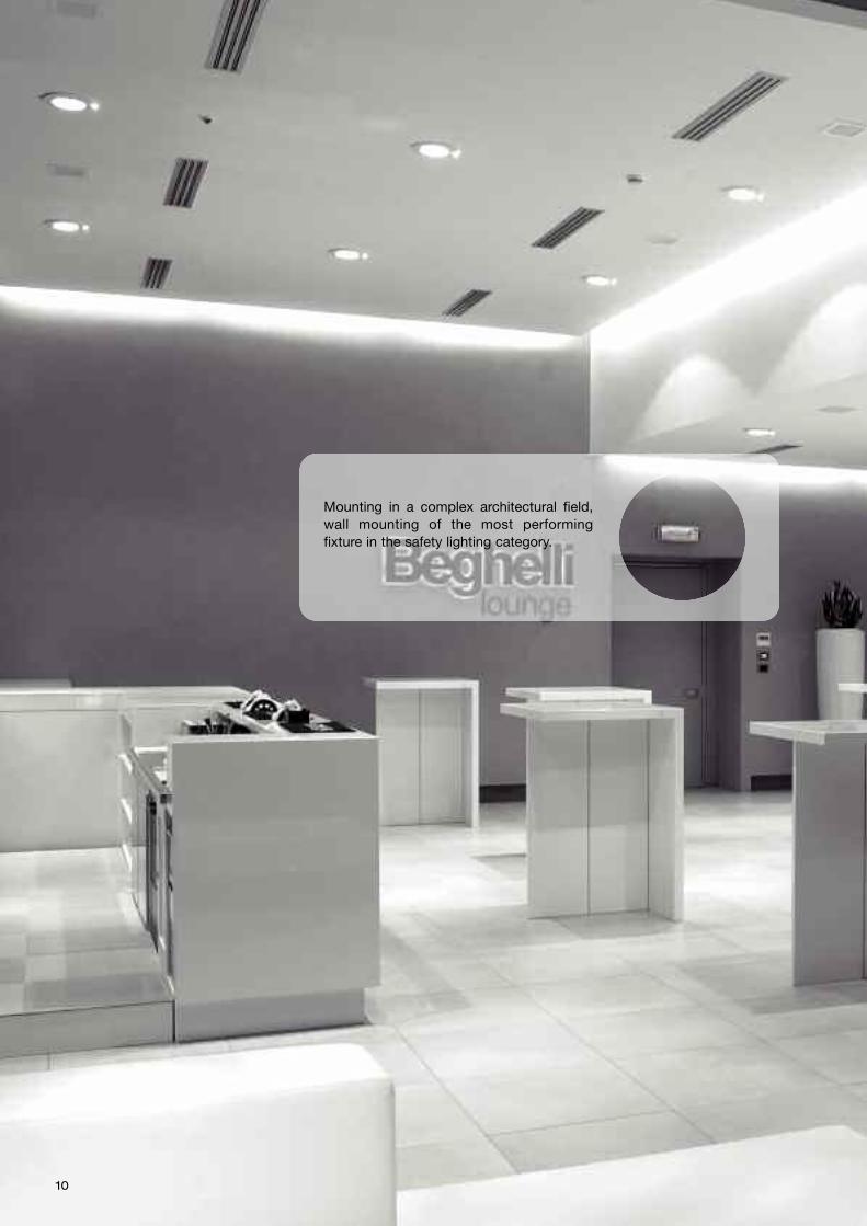
Mounting in a complex architectural field,wall mounting of the most performingfixture in the safety lighting category.
11
EM
ER
GE
NC
Y F
IXTU
RE
S
12
13
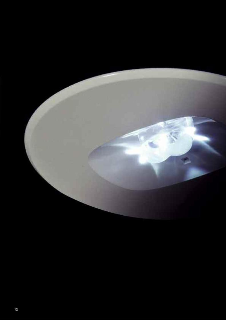
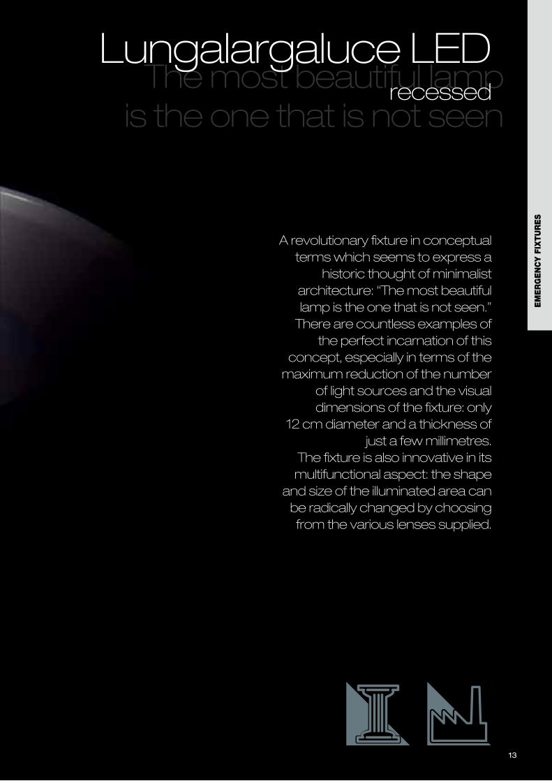
A revolutionary fixture in conceptualterms which seems to express a
historic thought of minimalistarchitecture: “The most beautifullamp is the one that is not seen.”There are countless examples of
the perfect incarnation of thisconcept, especially in terms of themaximum reduction of the number
of light sources and the visualdimensions of the fixture: only
12 cm diameter and a thickness ofjust a few millimetres.
The fixture is also innovative in itsmultifunctional aspect: the shape
and size of the illuminated area canbe radically changed by choosingfrom the various lenses supplied.
The most beautiful lamp is the one that is not seen
Lungalargaluce LEDrecessed
EM
ER
GE
NC
Y F
IXTU
RE
S
B
C(Hole Ø)
A
14
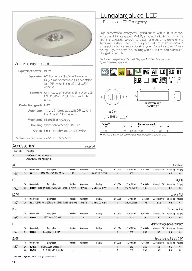
High-performance emergency lighting fixture with a kit of speciallenses in highly transparent PMMA, supplied for both the Lungaluceand the Largaluce version, to obtain different dimensions of theilluminated surface. Each lens is supplied with an aesthetic mask inwhite polycarbonate, with a blocking system for various types of falseceiling. High-efficiency Led, housing with built-in heat sink in graphite-charged polyamide.
Photometric diagrams and Luce Utile page 143, Symbols on cover,Spare batteries page 154
Lungalargaluce LEDRecessed LED Emergency
GENERAL CHARACTERISTICS
Equivalent power* 24 W
Operation HT, Permanent (SA)/Non Permanent(SE)/Public performance (PS) selectablewith DIP switch in the LG and LGFMversions
Standard UNI 11222, EN 60598-1, EN 60598-2-2,EN 60598-2-22, CEI EN 62471, EN62034
Protection grade IP42
Autonomy 1h, 2h, 3h selectable with DIP switch inthe LG and LGFM versions
Mountings false ceiling, recessed
Housing White polycarbonate RAL 9010
Optics lenses in highly transparent PMMA
* Indicative power for comparison with fluorescent tube fixtures
24 120 28 80 ÷100 204 63 46
** Indicative power for comparison with fluorescent tube fixtures
Power** • Dimensions (mm) •W A B C L G H
- LUNGALUCE lens with cover
- LARGALUCE lens with cover
Accessories suppliedOrder Code Description
* Minimum flux guaranteed according to EN 60598-2-22
19332 L.LARG DW RC LG 24W SE/SA/PS 1/2/3H SE/SA/PS 1/2/3h NiMH 7.2V 1.2Ah 1 250/190/165 165 1/6.5 0.8 6
Order Code Description Version Autonomy Battery n° LEDs Flux* SE lm Flux SA lm Absorption W Weight kg PackagingW
LG Logica
24
19331 L.LARG DW RC AT 24W SE 1N SE 1h NiCd 7.2V 0.75Ah 1 250 - 1 0.8 6
Order Code Description Version Autonomy Battery n° LEDs Flux* SE lm Flux SA lm Absorption W Weight kg PackagingW
AT AutoTest
24
19333L.LARG DW RC LGFM 24W SE/SA/PS 1/2/3H SE/SA/PS 1/2/3h NiMH 7.2V 1.2Ah 1 250/190/165 165 2/7.5 0.8 6
Order Code Description Version Autonomy Battery n° LEDs Flux* SE lm Flux SA lm Absorption W Weight kg PackagingW
LGFM Logica FM
24
17466 L.LARG DW RC SLG 24W - - - 1 250 250 5.5 0.7 6
Order Code Description Version Autonomy Battery n° LEDs Flux* SE lm Flux SA lm Absorption W Weight kg PackagingW
SLG Soccorlogica
24
19330 L.LARG DW RC HT 24W - - - 1 250 250 5.5 0.7 6
Order Code Description Version Autonomy Battery n° LEDs Flux* SE lm Flux SA lm Absorption W Weight kg PackagingW
HT Mains voltage power supply
24
17492 L.LARGA DWRC SY SLGS 24V - - - 1 250 250 5.5 0.7 6
17493 L.LARGA DWRC ASY SLGS 24V - - - 1 250 250 5.5 0.7 6
Order Code Description Version Autonomy Battery n° LEDs Flux* SE lm Flux SA lm Absorption W Weight kg PackagingW
SLGS Soccorlogica Sicuro 24V
24
24
L
H
G
INVERTER ANDBATTERIES
UV
IP42IK07 12 HOURS
RECHARGE
AT HTLG SLGSLGS
230V50Hz
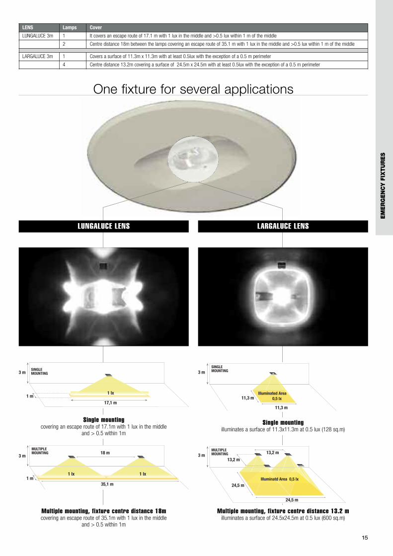
LENS Lamps Cover
LUNGALUCE 3m 1 It covers an escape route of 17.1 m with 1 lux in the middle and >0.5 lux within 1 m of the middle
2 Centre distance 18m between the lamps covering an escape route of 35.1 m with 1 lux in the middle and >0.5 lux within 1 m of the middle
LARGALUCE 3m 1 Covers a surface of 11.3m x 11.3m with at least 0.5lux with the exception of a 0.5 m perimeter
4 Centre distance 13.2m covering a surface of 24.5m x 24.5m with at least 0.5lux with the exception of a 0.5 m perimeter
15
3 m
17,1 m
1 lx1 m
SINGLEMOUNTING
3 m18 m
35,1 m
MULTIPLEMOUNTING
1 m1 lx 1 lx
11,3 m
11,3 m
3 mSINGLE MOUNTING
Illuminated Area 0,5 lxminated Aream 0,5 lx
Illum m
24,5 m
24,5 m
3 m13,2 m
13,2 m
Illuminatd Area 0,5 lx
MULTIPLEMOUNTING
l Are lIl d Il Il
Single mountingcovering an escape route of 17.1m with 1 lux in the middle
and > 0.5 within 1m
Multiple mounting, fixture centre distance 18mcovering an escape route of 35.1m with 1 lux in the middle
and > 0.5 within 1m
Single mountingilluminates a surface of 11.3x11.3m at 0.5 lux (128 sq.m)
Multiple mounting, fixture centre distance 13.2 milluminates a surface of 24.5x24.5m at 0.5 lux (600 sq.m)
LUNGALUCE LENS LARGALUCE LENS
One fixture for several applications
EM
ER
GE
NC
Y F
IXTU
RE
S
16

17
EM
ER
GE
NC
Y F
IXTU
RE
S
Positioning on an escape route with designrequirements and in the presence of thepublic: a single recessed fixture illuminatesa path of up to 18 metres.

18

A revolutionary fixture in conceptualterms which seems to express a
historic thought of minimalistarchitecture: “The most beautifullamp is the one that is not seen.”There are countless examples of
the perfect incarnation of thisconcept, especially in terms of themaximum reduction of the number
of light sources and the visualdimensions of the fixture: only 14
cm side length and 3 thick.The fixture is also innovative in itsmultifunctional aspect: the shape
and size of the illuminated area canbe radically changed by choosingfrom the various lenses supplied.
19
The most beautiful lampis the one that is not seen
Lungalargaluce LEDceiling
EM
ER
GE
NC
Y F
IXTU
RE
S

20
L
B H
24 137 137 32
** Indicative power for comparison with fluorescent tube fixtures
Power** • Dimensions (mm) •W L B H
High-performance emergency lighting fixture with a kit ofspecial lenses in highly transparent PMMA, supplied for theLungaluce, Largaluce and Diffusaluce versions, to obtaindifferent dimensions of the illuminated surface. Each lens issupplied with a suitable white polycarbonate housing. High-efficiency Led, housing with built-in heat sink in graphite-chargedpolyamide.
Photometric diagrams and Luce Utile page 143, Symbols on cover,Spare batteries page 154
Lungalargaluce LEDCeiling LED Emergency
GENERAL CHARACTERISTICS
Equivalent power* 24 W
Operation HT, Permanent (SA)/Non Permanent(SE)/Public performance (PS) selectablewith DIP switch in the LG and LGFMversions
Standard EN 60598-1, EN 60598-2-2, EN60598-2-22, UNI 11222, CEI EN62471, EN 62034
Protection grade IP42
Autonomy 1h, 2h, 3h selectable with DIP switch inthe LG and LGFM versions
Mountings ceiling, wall
Housing White polycarbonate RAL 9010
Optics lenses in highly transparent PMMA
* Indicative power for comparison with fluorescent tube fixtures
- LUNGALUCE lens with cover
- LARGALUCE lens with cover
- DIFFUSALUCE lens with cover
Accessories suppliedOrder Code Description
19322 L.LARG DW CL LG 24W SE/SA/PS 1/2/3H SE/SA/PS 1/2/3h NiMH 7.2V 1.2Ah 1 250/190/165 165 1/6.5 0.6 6
Order Code Description Version Autonomy Battery n° LEDs Flux* SE lm Flux SA lm Absorption W Weight kg PackagingW
LG Logica
24
19321 L.LARG DW CL AT 24W SE 1N SE 1h NiCd 7.2V 0.75Ah 1 250 - 1 0.6 6
Order Code Description Version Autonomy Battery n° LEDs Flux* SE lm Flux SA lm Absorption W Weight kg PackagingW
AT AutoTest
24
19323 L.LARG DW CL LGFM24W SE/SA/PS 1/2/3H SE/SA/PS 1/2/3h NiMH 7.2V 1.2Ah 1 250/190/165 165 2/7.5 0.6 6
Order Code Description Version Autonomy Battery n° LEDs Flux* SE lm Flux SA lm Absorption W Weight kg PackagingW
LGFM Logica FM
24
UV
IP42IK07 12 HOURS
RECHARGE
ATHT
LG SLGSLGSSLGS
230V50Hz
21
* Minimum flux guaranteed according to EN 60598-2-22
17464 L.LARG DW CL SLG 24W - - - 1 250 250 5.5 0.5 6
Order Code Description Version Autonomy Battery n° LEDs Flux* SE lm Flux SA lm Absorption W Weight kg PackagingW
SLG Soccorlogica
24
19320 L.LARG DW CL HT 24W - - - 1 250 250 5.5 0.5 6
Order Code Description Version Autonomy Battery n° LEDs Flux* SE lm Flux SA lm Absorption W Weight kg PackagingW
HT Mains voltage power supply
24
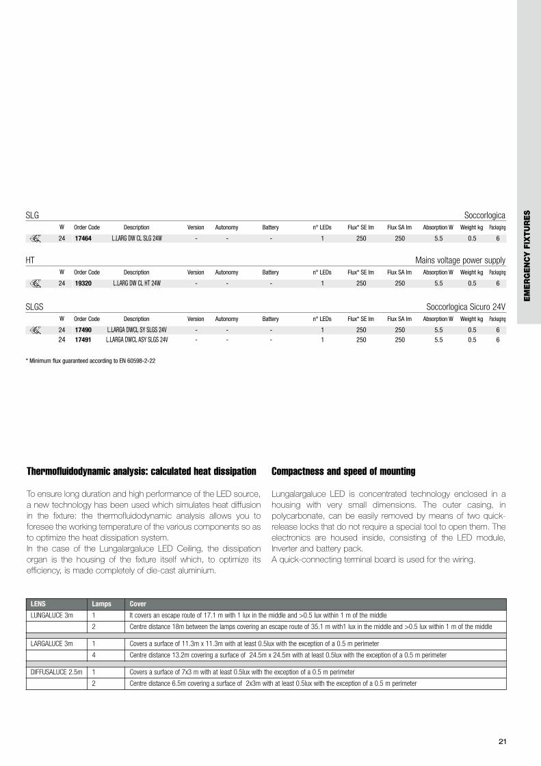
LENS Lamps Cover
LUNGALUCE 3m 1 It covers an escape route of 17.1 m with 1 lux in the middle and >0.5 lux within 1 m of the middle
2 Centre distance 18m between the lamps covering an escape route of 35.1 m with1 lux in the middle and >0.5 lux within 1 m of the middle
LARGALUCE 3m 1 Covers a surface of 11.3m x 11.3m with at least 0.5lux with the exception of a 0.5 m perimeter
4 Centre distance 13.2m covering a surface of 24.5m x 24.5m with at least 0.5lux with the exception of a 0.5 m perimeter
DIFFUSALUCE 2.5m 1 Covers a surface of 7x3 m with at least 0.5lux with the exception of a 0.5 m perimeter
2 Centre distance 6.5m covering a surface of 2x3m with at least 0.5lux with the exception of a 0.5 m perimeter
Thermofluidodynamic analysis: calculated heat dissipation
To ensure long duration and high performance of the LED source,a new technology has been used which simulates heat diffusionin the fixture: the thermofluidodynamic analysis allows you toforesee the working temperature of the various components so asto optimize the heat dissipation system. In the case of the Lungalargaluce LED Ceiling, the dissipationorgan is the housing of the fixture itself which, to optimize itsefficiency, is made completely of die-cast aluminium.
Compactness and speed of mounting
Lungalargaluce LED is concentrated technology enclosed in ahousing with very small dimensions. The outer casing, inpolycarbonate, can be easily removed by means of two quick-release locks that do not require a special tool to open them. Theelectronics are housed inside, consisting of the LED module,Inverter and battery pack.A quick-connecting terminal board is used for the wiring.
17490 L.LARGA DWCL SY SLGS 24V - - - 1 250 250 5.5 0.5 6
17491 L.LARGA DWCL ASY SLGS 24V - - - 1 250 250 5.5 0.5 6
Order Code Description Version Autonomy Battery n° LEDs Flux* SE lm Flux SA lm Absorption W Weight kg PackagingW
SLGS Soccorlogica Sicuro 24V
24
24
EM
ER
GE
NC
Y F
IXTU
RE
S

22
Lungaluce lensmounted at a height of 3m it covers an escape
route of 17.1m with1 lux in the middle and > 0.5 within 1m
Largaluce lensmounted at a height of 3m it illuminates a surface
of 11.3x11.3m at 0.5 lux (128 sq.m)
Diffusaluce lensmounted on the wall at a height of 2.5m it
illuminates a surface of 7x3 m at 0.5 lux (21 sq.m)
One fixture for several applications

23
3 m
17,1 m
1 lx1 m
SINGLEMOUNTING
3 m18 m
35,1 m
MULTIPLEMOUNTING
1 m1 lx 1 lx
SINGLEMOUNTING
2,5 m
7 m
3 m Illuminated Area 0,5 lxMULTIPLEMOUNTING
2,5 m
6,5 m
12 m
3 m Illuminated Area 0,5 lx
11,3 m
11,3 m
3 mSINGLE MOUNTING
Illuminated Area 0,5 lxminated Aream 0,5 lx
Illum m
24,5 m
24,5 m
3 m13,2 m
13,2 m
Illuminatd Area 0,5 lx
MULTIPLEMOUNTING
l Are lIlluminatd A d Illuminatd A Illuminatd A
Single mountingcovering an escape route of 17.1m with1 lux in the middle and >0.5 within 1m
Multiple mounting, fixture centre distance 18mcovering an escape route of 35.1m with1 lux in the middle and > 0.5within 1m
Lungaluce lens - mounting 3 m above the ground
Largaluce lens - mounting 3 m above the ground
Single mountingilluminates a surface of 11.3x11.3m at 0.5 lux (128 sq.m)
Multiple mounting, fixture centre distance 13,2milluminates a surface of 24.5x24.5m at 0.5 lux (600 sq.m)
Technical demonstration of light output on the ground
Diffusaluce lens - mounting 2.5 m above the ground
Single mountingilluminates a surface of 7x3 m at 0.5 lux (21 sq.m)
Multiple mounting, fixture centre distance 6,5milluminates a surface of 12x3m at 0.5 lux (36 sq.m)
EM
ER
GE
NC
Y F
IXTU
RE
S
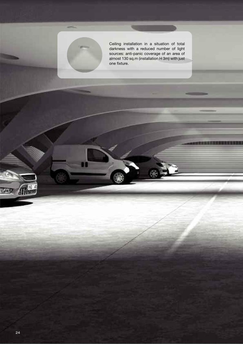
24
Ceiling installation in a situation of totaldarkness with a reduced number of lightsources: anti-panic coverage of an area ofalmost 130 sq.m (installation H 3m) with justone fixture.
25
EM
ER
GE
NC
Y F
IXTU
RE
S
262626
272727
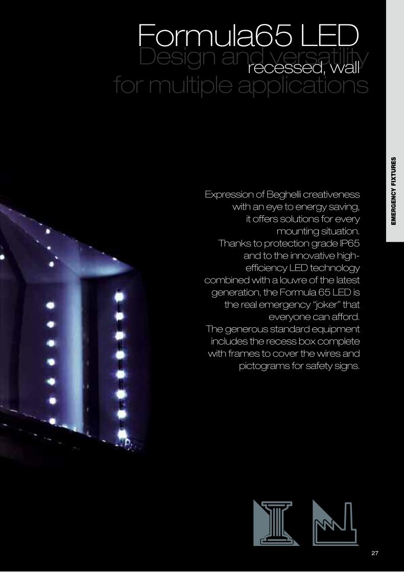
Expression of Beghelli creativenesswith an eye to energy saving,
it offers solutions for everymounting situation.
Thanks to protection grade IP65and to the innovative high-efficiency LED technology
combined with a louvre of the latestgeneration, the Formula 65 LED isthe real emergency “joker” that
everyone can afford.The generous standard equipmentincludes the recess box completewith frames to cover the wires and
pictograms for safety signs.
Design and versatility for multiple applications
Formula65 LEDrecessed, wall
EM
ER
GE
NC
Y F
IXTU
RE
S
282828
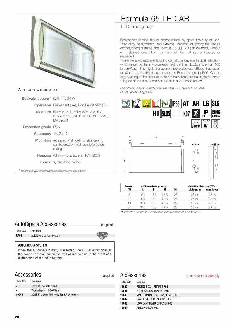
Formula 65 LED ARLED Emergency
Emergency lighting fixture characterized by great flexibility of use.Thanks to the symmetry and extreme uniformity of lighting that are itsdistinguishing features, the Formula 65 LED AR can be fitted, withouta predefined orientation, on the wall, the ceiling, cantilevered orrecessed.The white polycarbonate housing contains a louvre with dual reflection,which in turn contains two series of highly efficient LEDs (more than 100lumen/Watt). The highly transparent polycarbonate diffuser has beendesigned to seal the optics and obtain Protection grade IP65. On theouter casing of the product there are numerous pre-cut inlets for directfixing on all the most common junction and recess boxes.
Photometric diagrams and Luce Utile page 143, Symbols on cover,Spare batteries page 154
6 354 152 48.5 26 25 m 28 m8 354 152 48.5 26 25 m 28 m11 354 152 48.5 26 25 m 28 m24 354 152 48.5 26 25 m 28 m
** Indicative power for comparison with fluorescent tube fixtures
Power** • Dimensions (mm) • Visibility distance (DV)W L B H H1 pictogram cantilever
L
B
H H1
GENERAL CHARACTERISTICS
Equivalent power* 6, 8, 11, 24 W
Operation Permanent (SA), Non Permanent (SE)
Standard EN 60598-1, EN 60598-2-2, EN60598-2-22, UNI EN 1838, UNI 11222 ,EN 62034
Protection grade IP65
Autonomy 1h, 2h, 3h
Mounting recessed, wall, ceiling, false ceiling,cantilevered on wall, cantilevered onceiling
Housing White polycarbonate, RAL 9003
Louvre symmetrical, white
* Indicative power for comparison with fluorescent tube fixtures
19040 RECESS BOX + FRAMES F65
19041 FALSE CEILING BRACKET F65
19045 WALL BRACKET FOR CANTILEVER F65
19042 CANTILEVER DIFFUSER R/L F65
19043 LOW CANTILEVER DIFFUSER F65
19044 ADES R-L-LOW F65
Accessories to be ordered separatelyOrder Code Description
- Formula 65 cable gland
- Tube adapter 16/20 White
19044 ADES R-L-LOW F65 (only for SA versions)
Accessories suppliedOrder Code Description
RA01 AutoRipara battery system
AutoRipara Accessories suppliedOrder Code Description
AUTORIPARA SYSTEMWhen the Autoripara battery is inserted, the LED Inverter doublesthe power or the autonomy, as well as intervening in the event of amalfunction of the main battery
IK07IP65
12 HOURSRECHARGE
850°C UV
LG SLGHT
ARIP
PLUG230V50Hz
SLGSAT
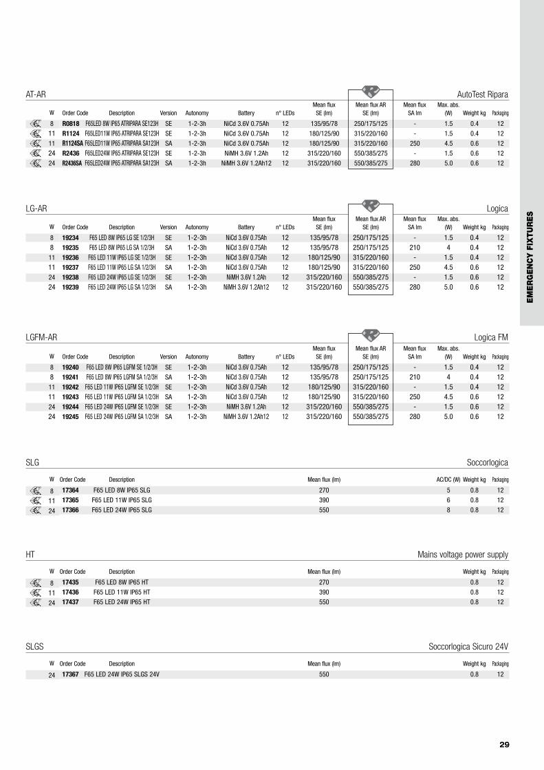
LG-AR Logica
292929
W
8
811
1124
24
17364 F65 LED 8W IP65 SLG 270 5 0.8 12
17365 F65 LED 11W IP65 SLG 390 6 0.8 12
17366 F65 LED 24W IP65 SLG 550 8 0.8 12
Order Code Description Mean flux (lm) AC/DC (W) Weight kg PackagingW
SLG Soccorlogica
8
1124
17435 F65 LED 8W IP65 HT 270 0.8 12
17436 F65 LED 11W IP65 HT 390 0.8 12
17437 F65 LED 24W IP65 HT 550 0.8 12
Order Code Description Mean flux (lm) Weight kg PackagingW
HT Mains voltage power supply
8
1124
17367 F65 LED 24W IP65 SLGS 24V 550 0.8 12
Order Code Description Mean flux (lm) Weight kg PackagingW
SLGS Soccorlogica Sicuro 24V
24
19234 F65 LED 8W IP65 LG SE 1/2/3H SE 1-2-3h NiCd 3.6V 0.75Ah 12 135/95/78 250/175/125 - 1.5 0.4 1219235 F65 LED 8W IP65 LG SA 1/2/3H SA 1-2-3h NiCd 3.6V 0.75Ah 12 135/95/78 250/175/125 210 4 0.4 1219236 F65 LED 11W IP65 LG SE 1/2/3H SE 1-2-3h NiCd 3.6V 0.75Ah 12 180/125/90 315/220/160 - 1.5 0.4 1219237 F65 LED 11W IP65 LG SA 1/2/3H SA 1-2-3h NiCd 3.6V 0.75Ah 12 180/125/90 315/220/160 250 4.5 0.6 1219238 F65 LED 24W IP65 LG SE 1/2/3H SE 1-2-3h NiMH 3.6V 1.2Ah 12 315/220/160 550/385/275 - 1.5 0.6 1219239 F65 LED 24W IP65 LG SA 1/2/3H SA 1-2-3h NiMH 3.6V 1.2Ah12 12 315/220/160 550/385/275 280 5.0 0.6 12
Mean flux Mean flux AR Mean flux Max. abs.Order Code Description Version Autonomy Battery n° LEDs SE (lm) SE (lm) SA lm (W) Weight kg Packaging
AT-AR AutoTest Ripara
W
8
1111
2424
R0818 F65LED 8W IP65 ATRIPARA SE123H SE 1-2-3h NiCd 3.6V 0.75Ah 12 135/95/78 250/175/125 - 1.5 0.4 12
R1124 F65LED11W IP65 ATRIPARA SE123H SE 1-2-3h NiCd 3.6V 0.75Ah 12 180/125/90 315/220/160 - 1.5 0.4 12
R1124SA F65LED11W IP65 ATRIPARA SA123H SA 1-2-3h NiCd 3.6V 0.75Ah 12 180/125/90 315/220/160 250 4.5 0.6 12
R2436 F65LED24W IP65 ATRIPARA SE123H SE 1-2-3h NiMH 3.6V 1.2Ah 12 315/220/160 550/385/275 - 1.5 0.6 12
R2436SA F65LED24W IP65 ATRIPARA SA123H SA 1-2-3h NiMH 3.6V 1.2Ah12 12 315/220/160 550/385/275 280 5.0 0.6 12
Mean flux Mean flux AR Mean flux Max. abs.Order Code Description Version Autonomy Battery n° LEDs SE (lm) SE (lm) SA lm (W) Weight kg Packaging
LGFM-AR Logica FM
W
8
811
1124
24
19240 F65 LED 8W IP65 LGFM SE 1/2/3H SE 1-2-3h NiCd 3.6V 0.75Ah 12 135/95/78 250/175/125 - 1.5 0.4 1219241 F65 LED 8W IP65 LGFM SA 1/2/3H SA 1-2-3h NiCd 3.6V 0.75Ah 12 135/95/78 250/175/125 210 4 0.4 1219242 F65 LED 11W IP65 LGFM SE 1/2/3H SE 1-2-3h NiCd 3.6V 0.75Ah 12 180/125/90 315/220/160 - 1.5 0.4 1219243 F65 LED 11W IP65 LGFM SA 1/2/3H SA 1-2-3h NiCd 3.6V 0.75Ah 12 180/125/90 315/220/160 250 4.5 0.6 1219244 F65 LED 24W IP65 LGFM SE 1/2/3H SE 1-2-3h NiMH 3.6V 1.2Ah 12 315/220/160 550/385/275 - 1.5 0.6 1219245 F65 LED 24W IP65 LGFM SA 1/2/3H SA 1-2-3h NiMH 3.6V 1.2Ah12 12 315/220/160 550/385/275 280 5.0 0.6 12
Mean flux Mean flux AR Mean flux Max. abs.Order Code Description Version Autonomy Battery n° LEDs SE (lm) SE (lm) SA lm (W) Weight kg Packaging
EM
ER
GE
NC
Y F
IXTU
RE
S
30
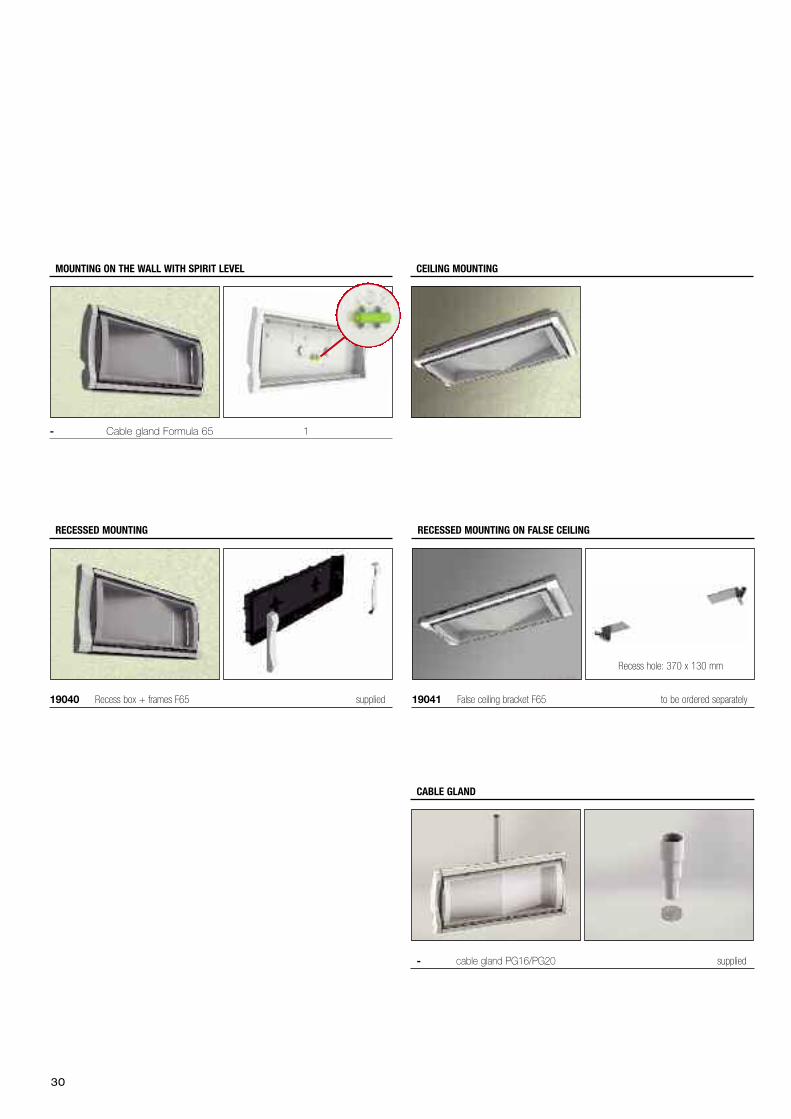
19040 Recess box + frames F65 supplied
RECESSED MOUNTING
MOUNTING ON THE WALL WITH SPIRIT LEVEL CEILING MOUNTING
- Cable gland Formula 65 1
19041 False ceiling bracket F65 to be ordered separately
RECESSED MOUNTING ON FALSE CEILING
Recess hole: 370 x 130 mm
- cable gland PG16/PG20 supplied
CABLE GLAND
31
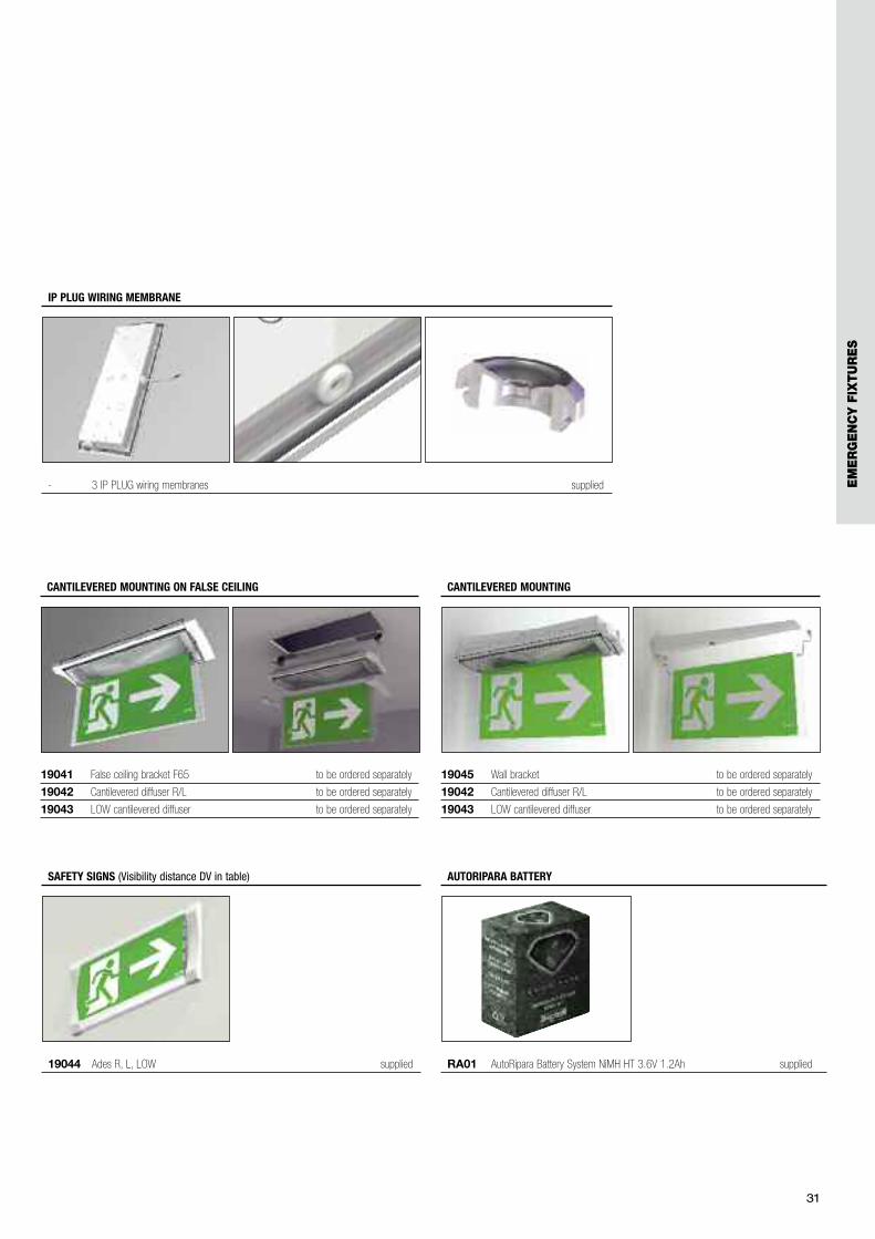
19045 Wall bracket to be ordered separately
19042 Cantilevered diffuser R/L to be ordered separately
19043 LOW cantilevered diffuser to be ordered separately
CANTILEVERED MOUNTING
19041 False ceiling bracket F65 to be ordered separately
19042 Cantilevered diffuser R/L to be ordered separately
19043 LOW cantilevered diffuser to be ordered separately
CANTILEVERED MOUNTING ON FALSE CEILING
- 3 IP PLUG wiring membranes supplied
IP PLUG WIRING MEMBRANE
19044 Ades R, L, LOW supplied
SAFETY SIGNS (Visibility distance DV in table)
RA01 AutoRipara Battery System NiMH HT 3.6V 1.2Ah supplied
AUTORIPARA BATTERY
EM
ER
GE
NC
Y F
IXTU
RE
S
32
33
EM
ER
GE
NC
Y F
IXTU
RE
S
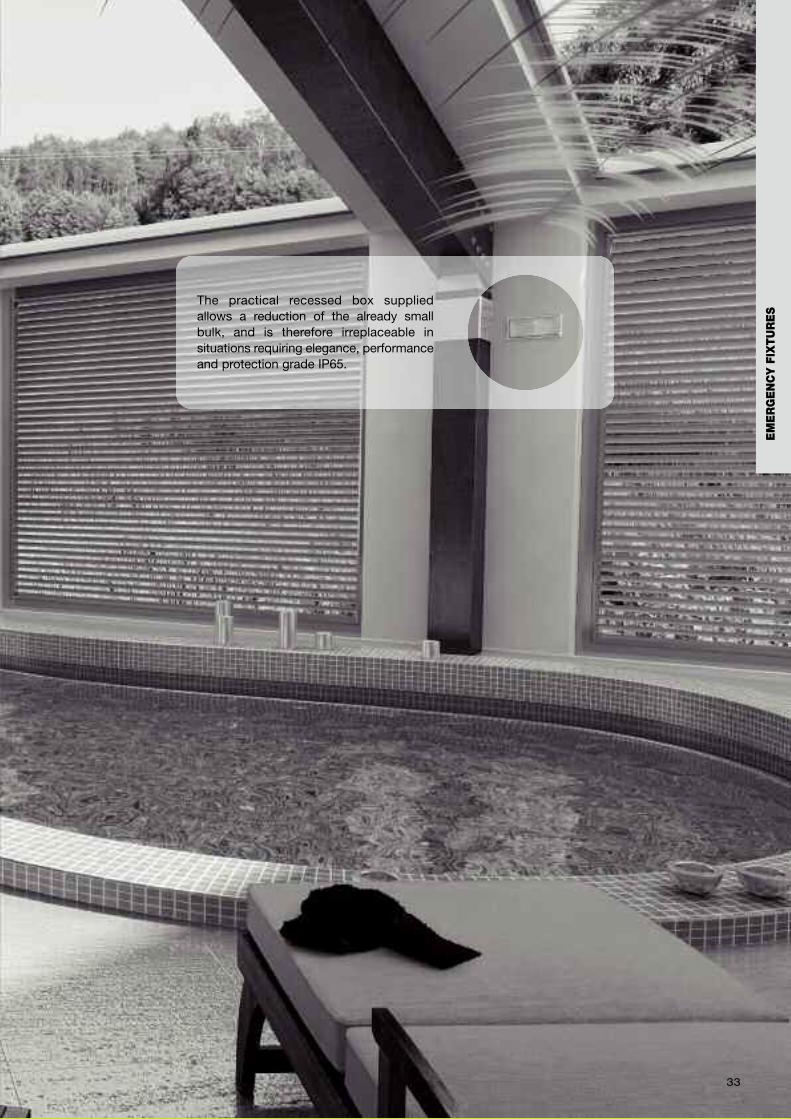
The practical recessed box suppliedallows a reduction of the already smallbulk, and is therefore irreplaceable insituations requiring elegance, performanceand protection grade IP65.
34

UP•LED is a fixture developed in only fiveversions but able to satisfy therequirements of a much wider range(from 6 to 36W, SE-SA-RM, autonomy 1-2-3h).The product concept is centred on arevolutionary optic system based on 4precision lenses able to exploit fully allthe power of the LEDs: for the first timea fixture has been made starting fromthe top of the available LEDs.The main characteristic of the UP•LEDis the very high illumination producedwith very compact dimensions. The24-36W version reaches 450 Lumenwith a thickness of less than 20 mm.With a view to multifunctionality,UP•LED is the first signalling fixture withthe possibility of applying two signs ofdifferent sizes on the same product,thus obtaining visibility distances (DV) of20 or 30 m.This system, totally innovative for theworld of safety signs, is designed bothto illuminate the sign powerfully anduniformly, but also to direct a beam oflight towards the ground, creating anilluminated area corresponding to theemergency exit over which the fixtureis placed. Not least is the mechanicalresult: despite the minimal appearanceand the smallest dimensions in thecategory, thanks also to the adoptionof O-Ring fixing systems on the wholehousing of the fixture and in theconnecting accessories, UP•LEDensures lasting Protection grade IP65and impact resistance IK07
LED technology, high resistance
UP•LEDtop performance, small bulk,
more functions
35
EM
ER
GE
NC
Y F
IXTU
RE
S
150
20
52,9
300
36
UP•LED
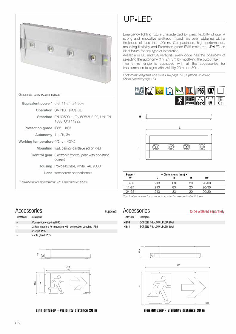
Emergency lighting fixture characterized by great flexibility of use. Astrong and innovative aesthetic impact has been obtained with athickness of less than 20mm. Compactness, high performance,mounting flexibility and Protection grade IP65 make the UP•LED anideal fixture for any type of installation.Available in SE and SA versions, every code has the possibility ofselecting the autonomy (1h, 2h, 3h) by modifying the output flux.The entire range is equipped with all the accessories fortransformation to signs with visibility 20m and 30m.
Photometric diagrams and Luce Utile page 143, Symbols on cover,Spare batteries page 154
GENERAL CHARACTERISTICS
Equivalent power* 6-8, 11-24, 24-36w
Operation SA INIBIT (RM), SE
Standard EN 60598-1, EN 60598-2-22, UNI EN1838, UNI 11222
Protection grade IP65 - IK07
Autonomy 1h, 2h, 3h
Working temperature 0°C ÷ +40°C
Mounting wall, ceiling, cantilevered on wall,
Control gear Electronic control gear with constantcurrent
Housing Polycarbonate, white RAL 9003
Lens transparent polycarbonate
* Indicative power for comparison with fluorescent tube fixtures
Power* • Dimensions (mm) •W L B H DV
6-8 213 83 20 20/3011-24 213 83 20 20/3024-36 213 83 20 20/30
* Indicative power for comparison with fluorescent tube fixtures
B
L
H
100
8320
42
213200
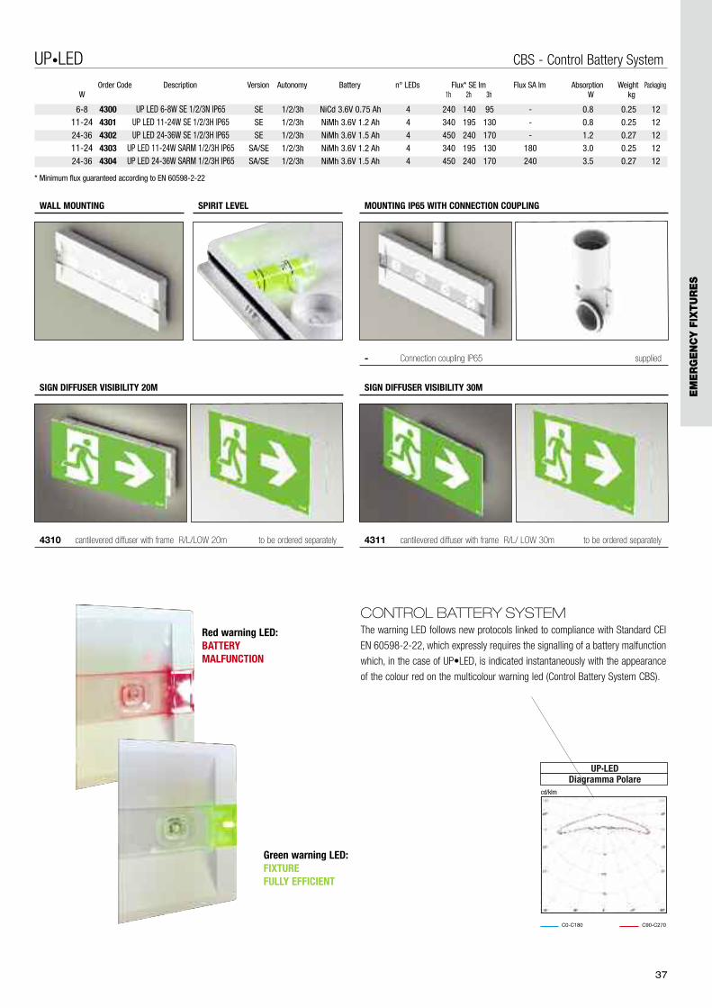
4310 SCREEN R-L-LOW UPLED 20M
4311 SCREEN R-L-LOW UPLED 30M
Accessories to be ordered separatelyOrder Code Description
- Connection coupling IP65
- 2 Rear spacers for mounting with connection coupling IP65
- 2 Caps IP65
- cable gland IP65
Accessories suppliedOrder Code Description
sign diffuser - visibility distance 30 msign diffuser - visibility distance 20 m
IK07IP65230V50Hz12 HOURS
RECHARGE UV850°C
37
4300 UP LED 6-8W SE 1/2/3N IP65 SE 1/2/3h NiCd 3.6V 0.75 Ah 4 240 140 95 - 0.8 0.25 12
4301 UP LED 11-24W SE 1/2/3H IP65 SE 1/2/3h NiMh 3.6V 1.2 Ah 4 340 195 130 - 0.8 0.25 12
4302 UP LED 24-36W SE 1/2/3H IP65 SE 1/2/3h NiMh 3.6V 1.5 Ah 4 450 240 170 - 1.2 0.27 12
4303 UP LED 11-24W SARM 1/2/3H IP65 SA/SE 1/2/3h NiMh 3.6V 1.2 Ah 4 340 195 130 180 3.0 0.25 12
4304 UP LED 24-36W SARM 1/2/3H IP65 SA/SE 1/2/3h NiMh 3.6V 1.5 Ah 4 450 240 170 240 3.5 0.27 12
Order Code Description Version Autonomy Battery n° LEDs Flux* SE lm Flux SA lm Absorption Weight Packaging1h 2h 3h W kgW
UP•LED CBS - Control Battery System
6-8
11-2424-36
11-2424-36
* Minimum flux guaranteed according to EN 60598-2-22
4311 cantilevered diffuser with frame R/L/ LOW 30m to be ordered separately
SIGN DIFFUSER VISIBILITY 30M
4310 cantilevered diffuser with frame R/L/LOW 20m to be ordered separately
SIGN DIFFUSER VISIBILITY 20M
WALL MOUNTING SPIRIT LEVEL
- Connection coupling IP65 supplied
MOUNTING IP65 WITH CONNECTION COUPLING
C0-C180 C90-C270
UP·LEDDiagramma Polare
cd/klm
CONTROL BATTERY SYSTEMThe warning LED follows new protocols linked to compliance with Standard CEI
EN 60598-2-22, which expressly requires the signalling of a battery malfunction
which, in the case of UP•LED, is indicated instantaneously with the appearance
of the colour red on the multicolour warning led (Control Battery System CBS).
Red warning LED: BATTERYMALFUNCTION
Green warning LED: FIXTURE FULLY EFFICIENT
EM
ER
GE
NC
Y F
IXTU
RE
S

38
39
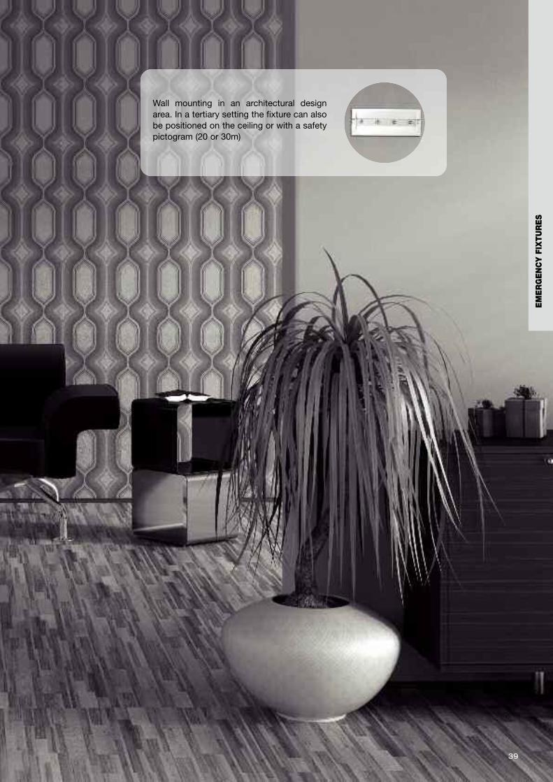
Wall mounting in an architectural designarea. In a tertiary setting the fixture can alsobe positioned on the ceiling or with a safetypictogram (20 or 30m)
EM
ER
GE
NC
Y F
IXTU
RE
S
40
UP•LED Multifor holes diam 60 mm
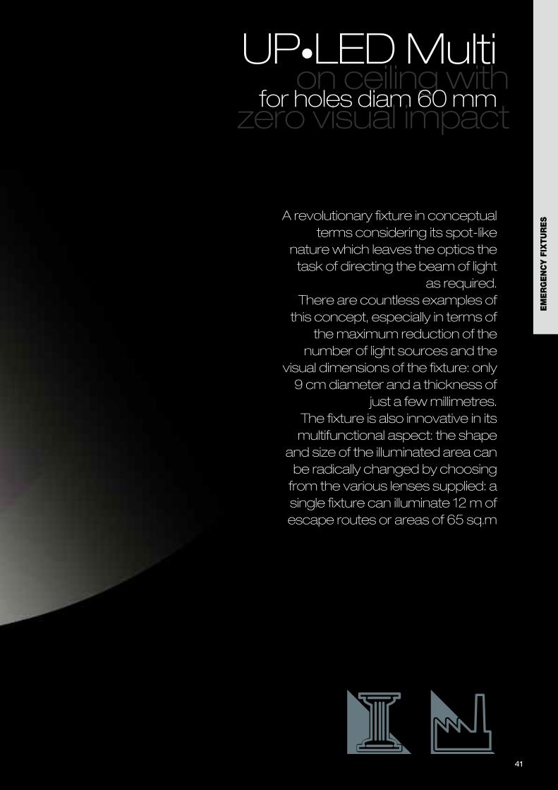
A revolutionary fixture in conceptualterms considering its spot-like
nature which leaves the optics thetask of directing the beam of light
as required.There are countless examples ofthis concept, especially in terms of
the maximum reduction of thenumber of light sources and the
visual dimensions of the fixture: only9 cm diameter and a thickness of
just a few millimetres.The fixture is also innovative in itsmultifunctional aspect: the shape
and size of the illuminated area canbe radically changed by choosingfrom the various lenses supplied: asingle fixture can illuminate 12 m ofescape routes or areas of 65 sq.m
41
EM
ER
GE
NC
Y F
IXTU
RE
S
on ceiling with zero visual impact
UP•LED Multifor holes diam 60 mm
42
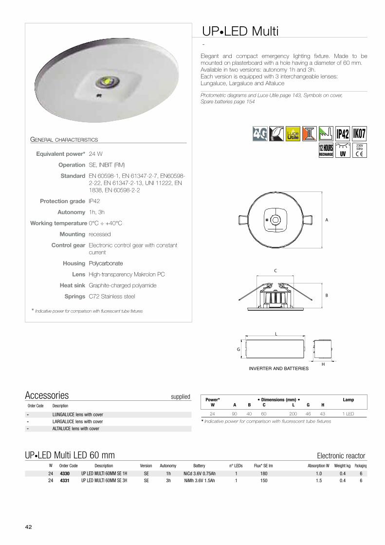
UP•LED Multi-
Elegant and compact emergency lighting fixture. Made to bemounted on plasterboard with a hole having a diameter of 60 mm. Available in two versions: autonomy 1h and 3h. Each version is equipped with 3 interchangeable lenses: Lungaluce, Largaluce and Altaluce
Photometric diagrams and Luce Utile page 143, Symbols on cover,Spare batteries page 154
GENERAL CHARACTERISTICS
Equivalent power* 24 W
Operation SE, INIBIT (RM)
Standard EN 60598-1, EN 61347-2-7, EN60598-2-22, EN 61347-2-13, UNI 11222, EN1838, EN 60598-2-2
Protection grade IP42
Autonomy 1h, 3h
Working temperature 0°C ÷ +40°C
Mounting recessed
Control gear Electronic control gear with constantcurrent
Housing Polycarbonate
Lens High-transparency Makrolon PC
Heat sink Graphite-charged polyamide
Springs C72 Stainless steel
* Indicative power for comparison with fluorescent tube fixtures
A
B
C
- LUNGALUCE lens with cover
- LARGALUCE lens with cover
- ALTALUCE lens with cover
Accessories suppliedOrder Code Description
4330 UP LED MULTI 60MM SE 1H SE 1h NiCd 3.6V 0.75Ah 1 180 1.0 0.4 6
4331 UP LED MULTI 60MM SE 3H SE 3h NiMh 3.6V 1.5Ah 1 150 1.5 0.4 6
Order Code Description Version Autonomy Battery n° LEDs Flux* SE lm Absorption W Weight kg PackagingW
UP•LED Multi LED 60 mm Electronic reactor
24
24
24 90 40 60 200 46 43 1 LED
* Indicative power for comparison with fluorescent tube fixtures
Power* • Dimensions (mm) • LampW A B C L G H
L
H
G
INVERTER AND BATTERIES
IP42 IK07230V50Hz12 HOURS
RECHARGE UV
43
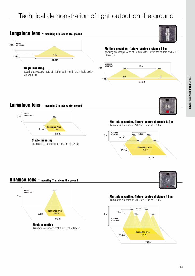
Technical demonstration of light output on the ground
3 m
11,8 m
1 lx1 m
SINGLEMOUNTING
3 m13 m
24,8 m
MULTIPLEMOUNTING
1 m1 lx 1 lx
9,3 m
9,3 m
7 m
Illuminated Area 0,5 lx
Illuminated Area 0,5 lx
Illuminated AreaIlluminated AreaIlluminated AreaIlluminated AreaIlluminated Area
SINGLEMOUNTING
20,5m
20,5 m
7 m11 m
11 m
Illuminated Area 0,5 lx
Illuminated Area 0,5 lx
Illuminated AreaIlluminated AreaIlluminated AreaIlluminated Area 0,5 lx
Illuminated Area 0,5 lx
Illuminated Area 0,5 lx 0,5 lx
Illuminated AreaIlluminated AreaIlluminated AreaIlluminated Area 0,5 lx 0,5 lx 0,5 lx
Illuminated AreaIlluminated AreaIlluminated AreaIlluminated Area 0,5 lx 0,5 lx
Illuminated Area 0,5 lx 0,5 lx 0,5 lx 0,5 lx
Illuminated Area 0,5 lx 0,5 lx 0,5 lx 0,5 lx 0,5 lx
Illuminated Area 0,5 lx
Illuminated Area 0,5 lx
MULTIPLEMOUNTING
8,1 m
8,1 m
3 mSINGLEMOUNTING
Illuminated Area 0,5 lx
16,7 m
16,7 m
3 m8,6 m
8,6 m
Illuminated Area 0,5 lx
MULTIPLEMOUNTING
Illuminated Area 0,5 lx 0,5 lx 0,5 lx 0,5 lx 0,5 lx 0,5 lx 0,5 lx 0,5 lx 0,5 lx 0,5 lx 0,5 lx
Illuminated Area
Single mountingcovering an escape route of 11.8 m with1 lux in the middle and >0.5 within 1m
Multiple mounting, fixture centre distance 13 mcovering an escape route of 24.8 m with1 lux in the middle and > 0.5within 1m
Lungaluce lens - mounting 3 m above the ground
Largaluce lens - mounting 3 m above the ground
Single mountingilluminates a surface of 8.1x8.1 m at 0.5 lux
Multiple mounting, fixture centre distance 8.6 milluminates a surface of 16.7 x 16.7 m at 0.5 lux
Altaluce lens - mounting 7 m above the ground
Single mountingilluminates a surface of 9.3 x 9.3 m at 0.5 lux
Multiple mounting, fixture centre distance 11 milluminates a surface of 20.5 x 20.5 m at 0.5 lux
EM
ER
GE
NC
Y F
IXTU
RE
S
44
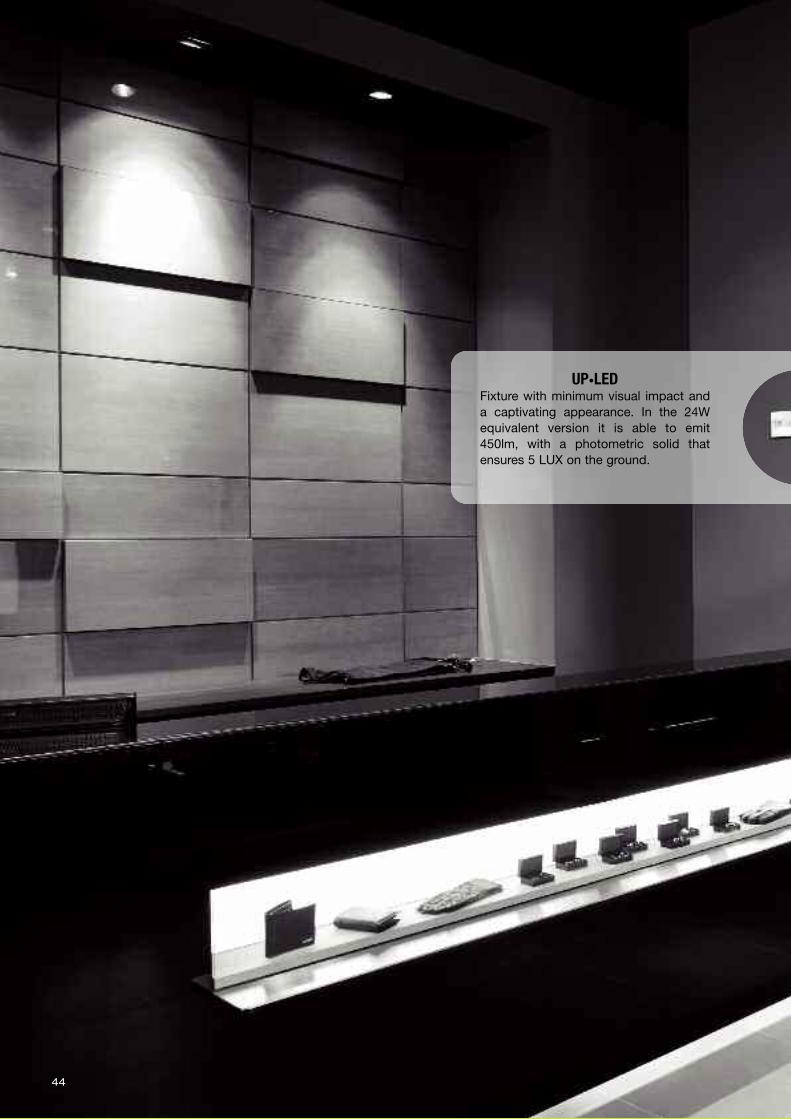
UP•LED Fixture with minimum visual impact anda captivating appearance. In the 24Wequivalent version it is able to emit450lm, with a photometric solid thatensures 5 LUX on the ground.
45
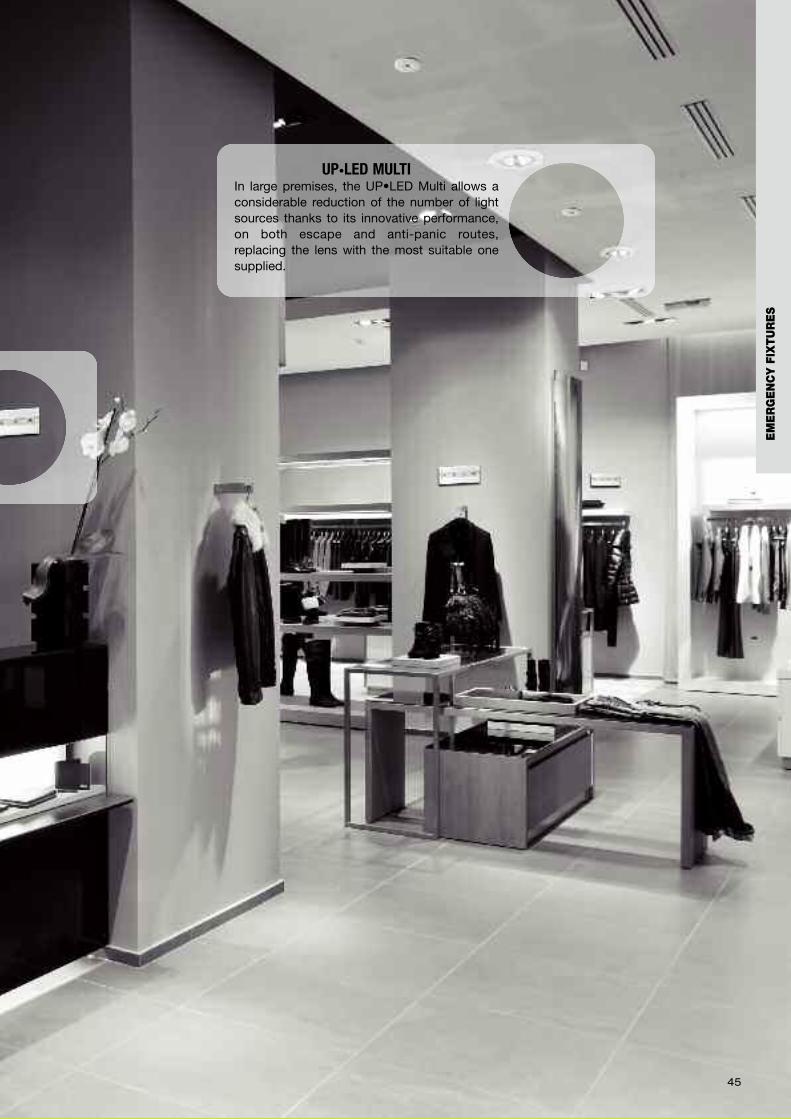
UP•LED MULTIIn large premises, the UP•LED Multi allows aconsiderable reduction of the number of lightsources thanks to its innovative performance,on both escape and anti-panic routes,replacing the lens with the most suitable onesupplied.
EM
ER
GE
NC
Y F
IXTU
RE
S
464646
474747
An IP65 fixture that is able tocombine clean lines with a
particularly captivating louvre, “itdoes not go unnoticed” and is idealfor particularly technical or modern
environments; the possibility ofmounting it recessed in the wallalso satisfies the most refined
aesthetic demands. GranluceLEDalso has an ecological heart that
pays attention to energy saving: thebattery charging system constantlyreads the level of residual energyso as to reduce absorption oncethe cycle has been completed.
Design and versatility for multiple applications
Granluce LEDversion 1 LED, 2 LED
EM
ER
GE
NC
Y F
IXTU
RE
S
48
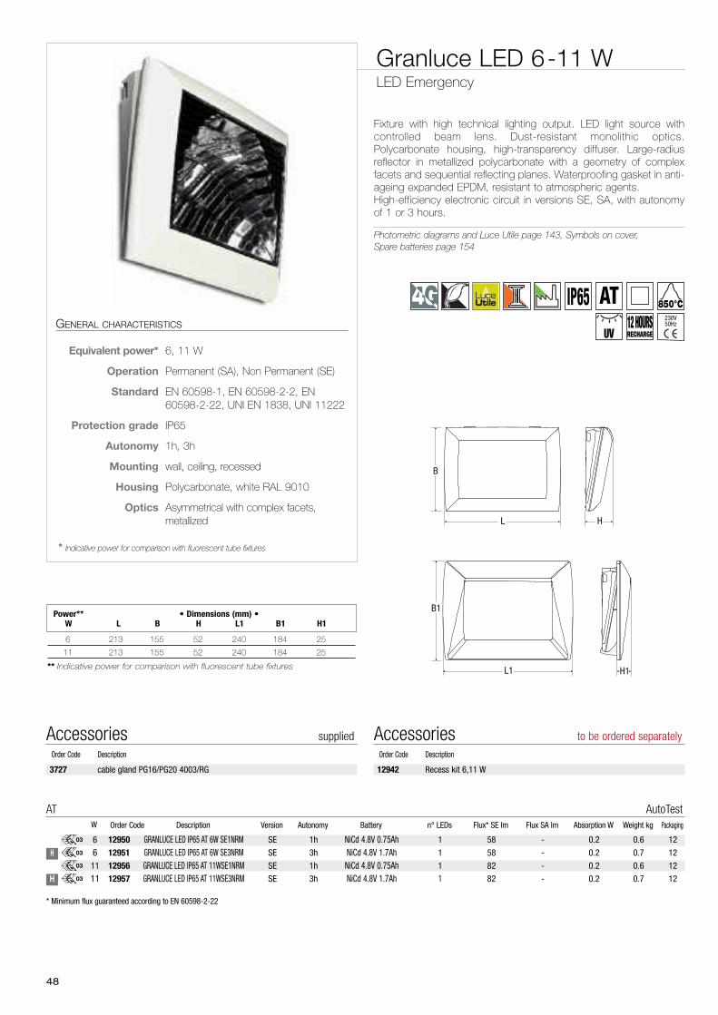
Fixture with high technical lighting output. LED light source withcontrolled beam lens. Dust-resistant monolithic optics.Polycarbonate housing, high-transparency diffuser. Large-radiusreflector in metallized polycarbonate with a geometry of complexfacets and sequential reflecting planes. Waterproofing gasket in anti-ageing expanded EPDM, resistant to atmospheric agents.High-efficiency electronic circuit in versions SE, SA, with autonomyof 1 or 3 hours.
Photometric diagrams and Luce Utile page 143, Symbols on cover,Spare batteries page 154
Granluce LED 6-11 WLED Emergency
GENERAL CHARACTERISTICS
Equivalent power* 6, 11 W
Operation Permanent (SA), Non Permanent (SE)
Standard EN 60598-1, EN 60598-2-2, EN60598-2-22, UNI EN 1838, UNI 11222
Protection grade IP65
Autonomy 1h, 3h
Mounting wall, ceiling, recessed
Housing Polycarbonate, white RAL 9010
Optics Asymmetrical with complex facets,metallized
* Indicative power for comparison with fluorescent tube fixtures
L H
B
L1
B1
H1
6
611
11
H
H
03
03
03
03
* Minimum flux guaranteed according to EN 60598-2-22
12950 GRANLUCE LED IP65 AT 6W SE1NRM SE 1h NiCd 4.8V 0.75Ah 1 58 - 0.2 0.6 12
12951 GRANLUCE LED IP65 AT 6W SE3NRM SE 3h NiCd 4.8V 1.7Ah 1 58 - 0.2 0.7 12
12956 GRANLUCE LED IP65 AT 11WSE1NRM SE 1h NiCd 4.8V 0.75Ah 1 82 - 0.2 0.6 12
12957 GRANLUCE LED IP65 AT 11WSE3NRM SE 3h NiCd 4.8V 1.7Ah 1 82 - 0.2 0.7 12
Order Code Description Version Autonomy Battery n° LEDs Flux* SE lm Flux SA lm Absorption W Weight kg PackagingW
AT AutoTest
6 213 155 52 240 184 25
11 213 155 52 240 184 25
** Indicative power for comparison with fluorescent tube fixtures
Power** • Dimensions (mm) •W L B H L1 B1 H1
3727 cable gland PG16/PG20 4003/RG
Accessories suppliedOrder Code Description
12942 Recess kit 6,11 W
Accessories to be ordered separatelyOrder Code Description
IP6512 HOURSRECHARGE
850°C
UV
AT230V50Hz
49
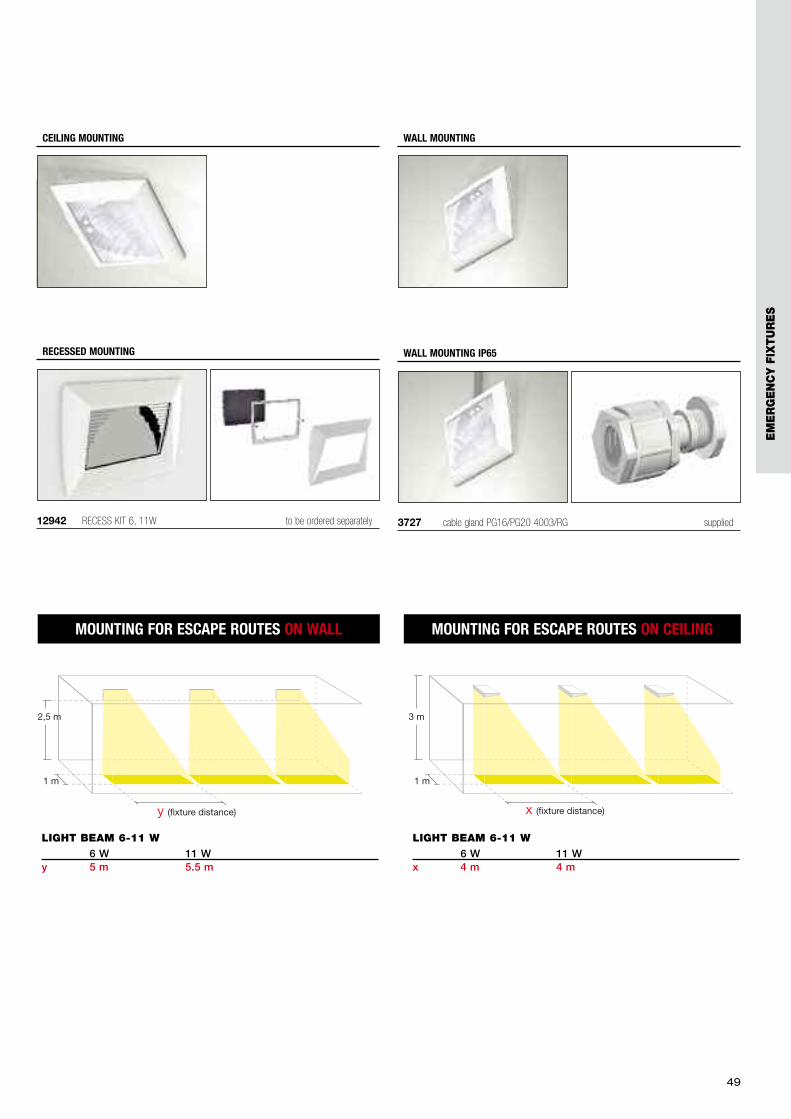
2,5 m
1 m
y (fixture distance)
LIGHT BEAM 6-11 W6 W 11 W
y 5 m 5.5 m
MOUNTING FOR ESCAPE ROUTES ON WALL MOUNTING FOR ESCAPE ROUTES ON CEILING
3 m
1 m
x (fixture distance)
LIGHT BEAM 6-11 W6 W 11 W
x 4 m 4 m
12942 RECESS KIT 6, 11W to be ordered separately
RECESSED MOUNTING
3727 cable gland PG16/PG20 4003/RG supplied
WALL MOUNTING IP65
WALL MOUNTINGCEILING MOUNTING
EM
ER
GE
NC
Y F
IXTU
RE
S
50
51
EM
ER
GE
NC
Y F
IXTU
RE
S
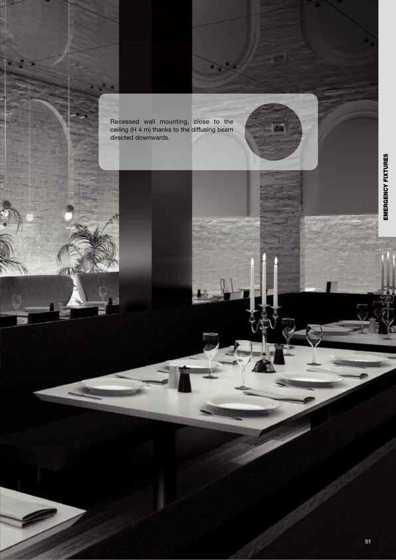
Recessed wall mounting, close to theceiling (H 4 m) thanks to the diffusing beamdirected downwards.
525252
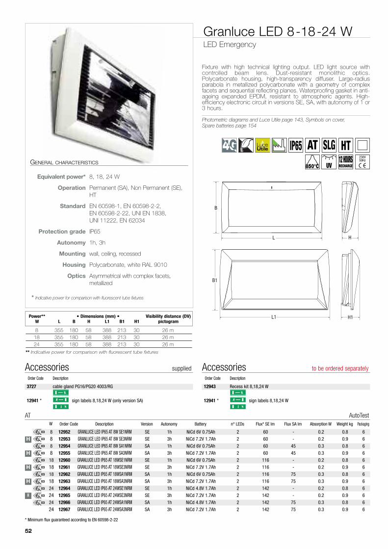
Fixture with high technical lighting output. LED light source withcontrolled beam lens. Dust-resistant monolithic optics.Polycarbonate housing, high-transparency diffuser. Large-radiusparabola in metallized polycarbonate with a geometry of complexfacets and sequential reflecting planes. Waterproofing gasket in anti-ageing expanded EPDM, resistant to atmospheric agents. High-efficiency electronic circuit in versions SE, SA, with autonomy of 1 or3 hours.
Photometric diagrams and Luce Utile page 143, Symbols on cover,Spare batteries page 154
Granluce LED 8-18-24 WLED Emergency
8
88
818
1818
1824
2424
24
H
H
H
H
H
03
03
03
03
03
03
03
03
03
03
03
GENERAL CHARACTERISTICS
Equivalent power* 8, 18, 24 W
Operation Permanent (SA), Non Permanent (SE),HT
Standard EN 60598-1, EN 60598-2-2,EN 60598-2-22, UNI EN 1838,UNI 11222, EN 62034
Protection grade IP65
Autonomy 1h, 3h
Mounting wall, ceiling, recessed
Housing Polycarbonate, white RAL 9010
Optics Asymmetrical with complex facets,metallized
* Indicative power for comparison with fluorescent tube fixtures
* Minimum flux guaranteed according to EN 60598-2-22
12952 GRANLUCE LED IP65 AT 8W SE1NRM SE 1h NiCd 6V 0.75Ah 2 60 - 0.2 0.8 6
12953 GRANLUCE LED IP65 AT 8W SE3NRM SE 3h NiCd 7.2V 1.7Ah 2 60 - 0.2 0.9 6
12954 GRANLUCE LED IP65 AT 8W SA1NRM SA 1h NiCd 6V 0.75Ah 2 60 45 0.3 0.8 6
12955 GRANLUCE LED IP65 AT 8W SA3NRM SA 3h NiCd 7.2V 1.7Ah 2 60 45 0.3 0.9 6
12960 GRANLUCE LED IP65 AT 18WSE1NRM SE 1h NiCd 6V 0.75Ah 2 116 - 0.2 0.8 6
12961 GRANLUCE LED IP65 AT 18WSE3NRM SE 3h NiCd 7.2V 1.7Ah 2 116 - 0.2 0.9 6
12962 GRANLUCE LED IP65 AT 18WSA1NRM SA 1h NiCd 6V 0.75Ah 2 116 75 0.3 0.8 6
12963 GRANLUCE LED IP65 AT 18WSA3NRM SA 3h NiCd 7.2V 1.7Ah 2 116 75 0.3 0.9 6
12964 GRANLUCE LED IP65 AT 24WSE1NRM SE 1h NiCd 4.8V 1.7Ah 2 142 - 0.2 0.8 6
12965 GRANLUCE LED IP65 AT 24WSE3NRM SE 3h NiCd 7.2V 1.7Ah 2 142 - 0.2 0.9 6
12966 GRANLUCE LED IP65 AT 24WSA1NRM SA 1h NiCd 4.8V 1.7Ah 2 142 75 0.3 0.8 6
12967 GRANLUCE LED IP65 AT 24WSA3NRM SA 3h NiCd 7.2V 1.7Ah 2 142 75 0.3 0.9 6
Order Code Description Version Autonomy Battery n° LEDs Flux* SE lm Flux SA lm Absorption W Weight kg PackagingW
AT AutoTest
8 355 180 58 388 213 30 26 m18 355 180 58 388 213 30 26 m24 355 180 58 388 213 30 26 m
** Indicative power for comparison with fluorescent tube fixtures
Power** • Dimensions (mm) • Visibility distance (DV)W L B H L1 B1 H1 pictogram
L H
B
L1
B1
H1
3727 cable gland PG16/PG20 4003/RG
12941 * sign labels 8,18,24 W (only version SA)
Accessories suppliedOrder Code Description
12943 Recess kit 8,18,24 W
12941 * sign labels 8,18,24 W
Accessories to be ordered separatelyOrder Code Description
SLG HTIP6512 HOURSRECHARGE850°C UV
AT230V50Hz

12942 RECESS KIT 6, 11W to be ordered separately
RECESSED MOUNTING
WALL MOUNTINGCEILING MOUNTING
3727 cable gland PG16/PG20 supplied
WALL MOUNTING IP65
535353
LIGHT BEAM 2 LED
Surface 20 sq.mIllumination 0.5 lux (on floor)
ANTI-PANIC MOUNTING ON WALL
LIGHT BEAM 2 LED
Surface 12 sq.mIllumination 0.5 lux (on floor)
ANTI-PANIC MOUNTING ON CEILING
2,5 m
1 m
y (fixture distance)
LIGHT BEAM 8-18-24 W8 W 18 W 24W
y 5.5 m 6.5 m 7.5 m
MOUNTING FOR ESCAPE ROUTES ON WALL MOUNTING FOR ESCAPE ROUTES ON CEILING
3 m
1 m
x (fixture distance)
LIGHT BEAM 8-18-24 W8 W 18 W 24W
x 4.5 m 5.5 m 7 m
* Minimum flux guaranteed according to EN 60598-2-22
17332 GRANLUCE 2LED SLG IP65 SE/SA 1/3h - 2 - - - 0.8 6
Order Code Description Version Autonomy Battery n° LEDs Flux* SE lm Flux SA lm Absorption W Weight kg PackagingW
SLG Soccorlogica
3.6
17422 GRANLUCE 2LED HT IP65 SE/SA 1-3h - 2 - - - 0.8 6
Order Code Description Version Autonomy Battery n° LEDs Flux* SE lm Flux SA lm Absorption W Weight kg PackagingW
HT Mains voltage power supply
3.6
EM
ER
GE
NC
Y F
IXTU
RE
S
54
55
EM
ER
GE
NC
Y F
IXTU
RE
S
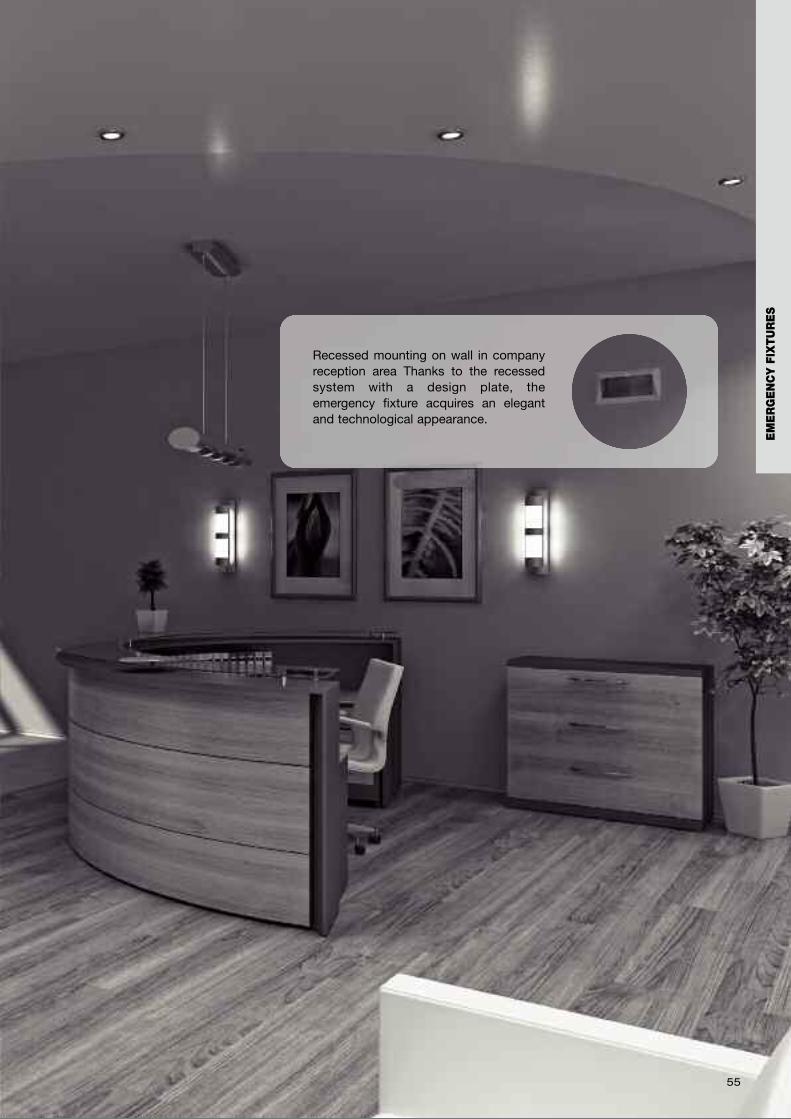
Recessed mounting on wall in companyreception area Thanks to the recessedsystem with a design plate, theemergency fixture acquires an elegantand technological appearance.
56
57
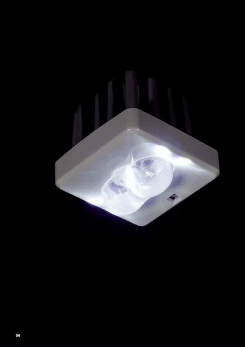
The advantages of high-efficiencyLED technology combined with
precision studies on lens refractionoffered the cue for a new conceptin emergency lighting. Followingthese principles, the Inverter with
LED Module was born, aminiaturized emergency fixture
equipped with a series ofaccessories that allow it to be fitted
on normal fixtures for traditionallighting. The great power of the lightbeam is intercepted by a series oflenses with controlled refractionthat are able to shape the samenumber of multifunctional light
beams.
Reinventing emergency lighting
LED modulewith built-in Inverter
EM
ER
GE
NC
Y F
IXTU
RE
S
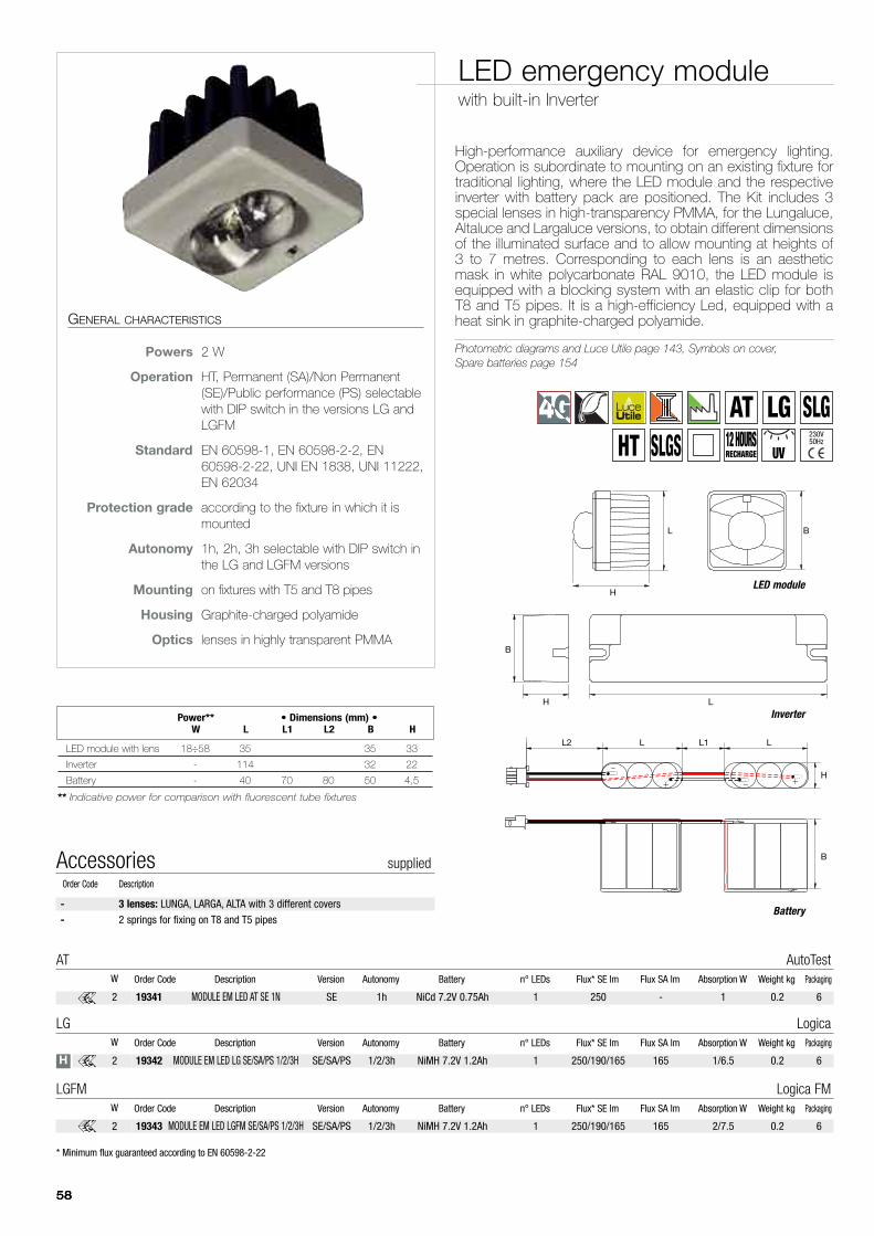
LED emergency modulewith built-in Inverter
585858
High-performance auxiliary device for emergency lighting.Operation is subordinate to mounting on an existing fixture fortraditional lighting, where the LED module and the respectiveinverter with battery pack are positioned. The Kit includes 3special lenses in high-transparency PMMA, for the Lungaluce,Altaluce and Largaluce versions, to obtain different dimensionsof the illuminated surface and to allow mounting at heights of3 to 7 metres. Corresponding to each lens is an aestheticmask in white polycarbonate RAL 9010, the LED module isequipped with a blocking system with an elastic clip for bothT8 and T5 pipes. It is a high-efficiency Led, equipped with aheat sink in graphite-charged polyamide.
Photometric diagrams and Luce Utile page 143, Symbols on cover,Spare batteries page 154
GENERAL CHARACTERISTICS
Powers 2 W
Operation HT, Permanent (SA)/Non Permanent(SE)/Public performance (PS) selectablewith DIP switch in the versions LG andLGFM
Standard EN 60598-1, EN 60598-2-2, EN60598-2-22, UNI EN 1838, UNI 11222,EN 62034
Protection grade according to the fixture in which it ismounted
Autonomy 1h, 2h, 3h selectable with DIP switch inthe LG and LGFM versions
Mounting on fixtures with T5 and T8 pipes
Housing Graphite-charged polyamide
Optics lenses in highly transparent PMMA
LED module with lens 18÷58 35 35 33
Inverter - 114 32 22
Battery - 40 70 80 50 4,5
** Indicative power for comparison with fluorescent tube fixtures
Power** • Dimensions (mm) •W L L1 L2 B H
L
B
H
H
BL
B
L1L2 L L
H
- 3 lenses: LUNGA, LARGA, ALTA with 3 different covers- 2 springs for fixing on T8 and T5 pipes
Accessories suppliedOrder Code Description
19342 MODULE EM LED LG SE/SA/PS 1/2/3H SE/SA/PS 1/2/3h NiMH 7.2V 1.2Ah 1 250/190/165 165 1/6.5 0.2 6
Order Code Description Version Autonomy Battery n° LEDs Flux* SE lm Flux SA lm Absorption W Weight kg PackagingW
LG Logica
2
19341 MODULE EM LED AT SE 1N SE 1h NiCd 7.2V 0.75Ah 1 250 - 1 0.2 6
Order Code Description Version Autonomy Battery n° LEDs Flux* SE lm Flux SA lm Absorption W Weight kg PackagingW
AT AutoTest
2
19343 MODULE EM LED LGFM SE/SA/PS 1/2/3H SE/SA/PS 1/2/3h NiMH 7.2V 1.2Ah 1 250/190/165 165 2/7.5 0.2 6
Order Code Description Version Autonomy Battery n° LEDs Flux* SE lm Flux SA lm Absorption W Weight kg PackagingW
LGFM Logica FM
2
LED module
Battery
Inverter
H
* Minimum flux guaranteed according to EN 60598-2-22
12 HOURSRECHARGE
AT LG SLGHT UVSLGS
230V50Hz
LENS Lamps Cover
LUNGALUCE 3m 1 It covers an escape route of 17.1 m with 1 lux in the middle and >0.5 lux within 1 m of the middle
2 Centre distance 18m between the lamps covering an escape route of 35.1 m with1 lux in the middle and >0.5 lux within 1 m of the middle
LARGA LUCE 3m 1 Covers a surface of 11.3m x 11.3m with at least 0.5lux with the exception of a 0.5 m perimeter
4 Centre distance 13.2m covering a surface of 24.5m x 24.5m with at least 0.5lux with the exception of a 0.5 m perimeter
ALTALUCE 7m 1 Covers a surface of 12.4m x 12.4m with at least 0.5lux with the exception of a 0.5 m perimeter
4 Centre distance 14.4m covering a surface of 26.8m x 26.8m with at least 0.5lux with the exception of a 0.5 m perimeter
595959
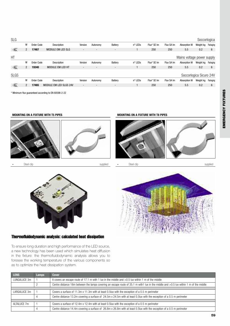
- Steel clip supplied
MOUNTING ON A FIXTURE WITH T5 PIPES
- Steel clip supplied
MOUNTING ON A FIXTURE WITH T8 PIPES
Thermofluidodynamic analysis: calculated heat dissipation
To ensure long duration and high performance of the LED source,a new technology has been used which simulates heat diffusionin the fixture: the thermofluidodynamic analysis allows you toforesee the working temperature of the various components soas to optimize the heat dissipation system.
* Minimum flux guaranteed according to EN 60598-2-22
17467 MODULE EM LED SLG - - - 1 250 250 5.5 0.2 6
Order Code Description Version Autonomy Battery n° LEDs Flux* SE lm Flux SA lm Absorption W Weight kg PackagingW
SLG Soccorlogica
2
17465 MODULE EM LED SLGS 24V - - - 1 250 250 5.5 0.2 6
Order Code Description Version Autonomy Battery n° LEDs Flux* SE lm Flux SA lm Absorption W Weight kg PackagingW
SLGS Soccorlogica Sicuro 24V
2
19340 MODULE EM LED HT - - - 1 250 250 5.5 0.2 6
Order Code Description Version Autonomy Battery n° LEDs Flux* SE lm Flux SA lm Absorption W Weight kg PackagingW
HT Mains voltage power supply
2
EM
ER
GE
NC
Y F
IXTU
RE
S
60
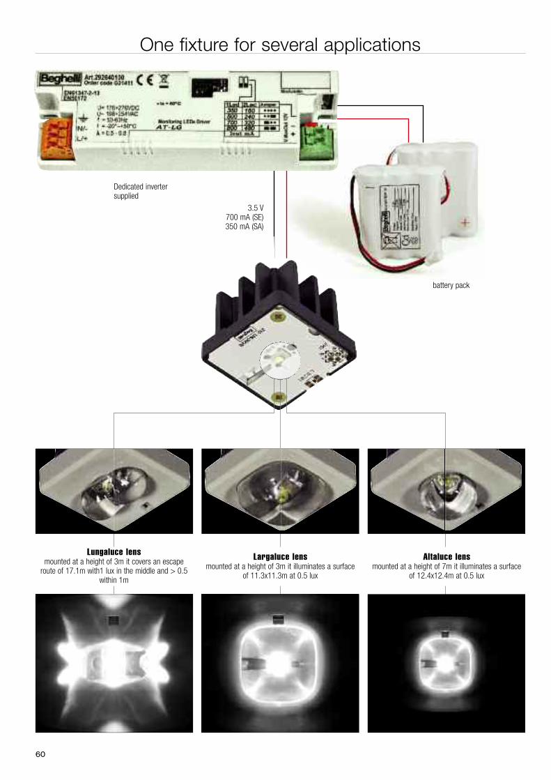
Dedicated invertersupplied
3.5 V700 mA (SE)350 mA (SA)
battery pack
One fixture for several applications
Lungaluce lensmounted at a height of 3m it covers an escape
route of 17.1m with1 lux in the middle and > 0.5within 1m
Largaluce lensmounted at a height of 3m it illuminates a surface
of 11.3x11.3m at 0.5 lux
Altaluce lensmounted at a height of 7m it illuminates a surface
of 12.4x12.4m at 0.5 lux
61
3 m
17,1 m
1 lx1 m
SINGLEMOUNTING
3 m18 m
35,1 m
MULTIPLEMOUNTING
1 m1 lx 1 lx
12,4 m
12,4 m
7 m
Illuminated Area 0,5 lx
Illuminated Area 0,5 lx
Illuminated AreaIlluminated AreaIlluminated AreaIlluminated AreaIlluminated Area
SINGLEMOUNTING
26,8 m
26,8 m
7 m13,7 m
13,7 m
Illuminated Area 0,5 lx
Illuminated Area 0,5 lx
Illuminated Area Illuminated Area Illuminated Area Illuminated Area Illuminated Area 0,5 lx
Illuminated Area 0,5 lx
Illuminated Area 0,5 lx 0,5 lx
Illuminated Area Illuminated Area Illuminated Area Illuminated Area 0,5 lx 0,5 lx 0,5 lx
Illuminated Area Illuminated Area Illuminated Area Illuminated Area 0,5 lx 0,5 lx
Illuminated Area 0,5 lx 0,5 lx 0,5 lx 0,5 lx
Illuminated Area 0,5 lx 0,5 lx 0,5 lx 0,5 lx 0,5 lx
Illuminated Area 0,5 lx
Illuminated Area 0,5 lx
MULTIPLEMOUNTING
11,3 m
11,3 m
3 mSINGLE MOUNTING
Illuminated Area 0,5 lx
Illuminated AreaIlluminated Area 0,5 lx 0,5 lx
Illuminated AreaIlluminated Area 0,5 lx 0,5 lx
Illuminated Area
24,5 m
24,5 m
3 m13,2 m
13,2 m
Illuminatd Area 0,5 lx
MULTIPLEMOUNTING
Illuminatd Area 0,5 lxIlluminatd Area 0,5 lxIlluminatd Area 0,5 lxIlluminatd Area 0,5 lxIlluminatd Area 0,5 lxIlluminatd Area 0,5 lxIlluminatd Area 0,5 lxIlluminatd Area 0,5 lxIlluminatd Area 0,5 lxIlluminatd Area 0,5 lxIlluminatd Area 0,5 lx
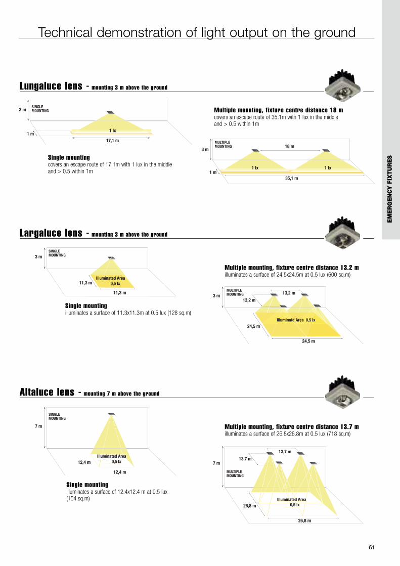
Single mountingcovers an escape route of 17.1m with 1 lux in the middle and > 0.5 within 1m
Multiple mounting, fixture centre distance 18 mcovers an escape route of 35.1m with 1 lux in the middle and > 0.5 within 1m
Lungaluce lens - mounting 3 m above the ground
Largaluce lens - mounting 3 m above the ground
Single mountingilluminates a surface of 11.3x11.3m at 0.5 lux (128 sq.m)
Multiple mounting, fixture centre distance 13.2 milluminates a surface of 24.5x24.5m at 0.5 lux (600 sq.m)
Technical demonstration of light output on the ground
Altaluce lens - mounting 7 m above the ground
Single mountingilluminates a surface of 12.4x12.4 m at 0.5 lux (154 sq.m)
Multiple mounting, fixture centre distance 13.7 milluminates a surface of 26.8x26.8m at 0.5 lux (718 sq.m)
EM
ER
GE
NC
Y F
IXTU
RE
S
62
63
EM
ER
GE
NC
Y F
IXTU
RE
S
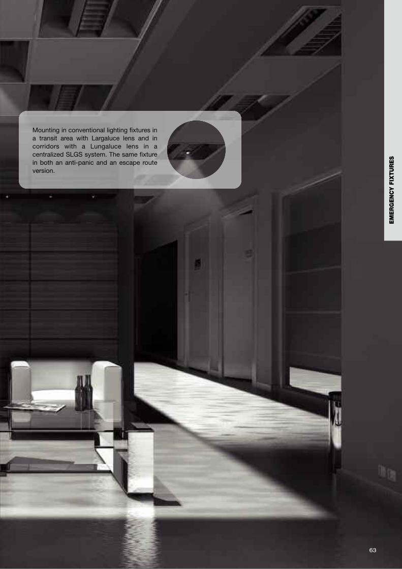
Mounting in conventional lighting fixtures ina transit area with Largaluce lens and incorridors with a Lungaluce lens in acentralized SLGS system. The same fixturein both an anti-panic and an escape routeversion.
64
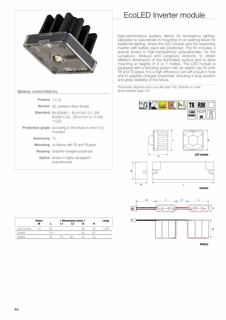
EcoLED Inverter module
High-performance auxiliary device for emergency lighting.Operation is subordinate to mounting on an existing fixture fortraditional lighting, where the LED module and the respectiveinverter with battery pack are positioned. The Kit includes 3special lenses in high-transparency polycarbonate, for theLungaluce, Altaluce and Largaluce versions, to obtaindifferent dimensions of the illuminated surface and to allowmounting at heights of 3 or 7 metres. The LED module isequipped with a blocking system with an elastic clip for bothT8 and T5 pipes. It is a high-efficiency Led with a built-in heatsink in graphite-charged polyamide, ensuring a long durationand great reliability of the fixture.
Photometric diagrams and Luce Utile page 143, Symbols on cover,Spare batteries page 154GENERAL CHARACTERISTICS
Powers 1.5 W
Version SE, Inhibition (Rest Mode)
Standard EN 60598-1, EN 61347-2-7, EN60598-2-22, , EN 61347-2-13 UNI11222
Protection grade according to the fixture in which it ismounted
Autonomy 1h
Mounting on fixtures with T5 and T8 pipes
Housing Graphite-charged polyamide
Optics lenses in highly transparentpolycarbonate
230V50Hz
TR RM12 HOURSRECHARGE UV
LED module 1.5 36 36 28 1 LED
Inverter - 114 32 22 -
Battery - 40 70 80 50 4.5 -
Power • Dimensions (mm) • LampW L L1 L2 B H
L
B
H
H
BL
B
L1L2 L L
H
LED module
Battery
Inverter
65
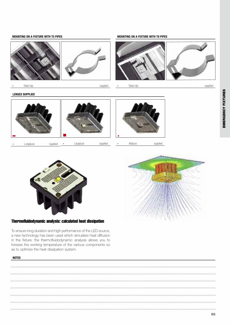
- Steel clip supplied
MOUNTING ON A FIXTURE WITH T5 PIPES
- Steel clip supplied
MOUNTING ON A FIXTURE WITH T8 PIPES
Thermofluidodynamic analysis: calculated heat dissipation
To ensure long duration and high performance of the LED source,a new technology has been used which simulates heat diffusionin the fixture: the thermofluidodynamic analysis allows you toforesee the working temperature of the various components soas to optimize the heat dissipation system.
NOTES
- Lungaluce supplied - Largaluce supplied - Altaluce supplied
LENSES SUPPLIED
EM
ER
GE
NC
Y F
IXTU
RE
S
66
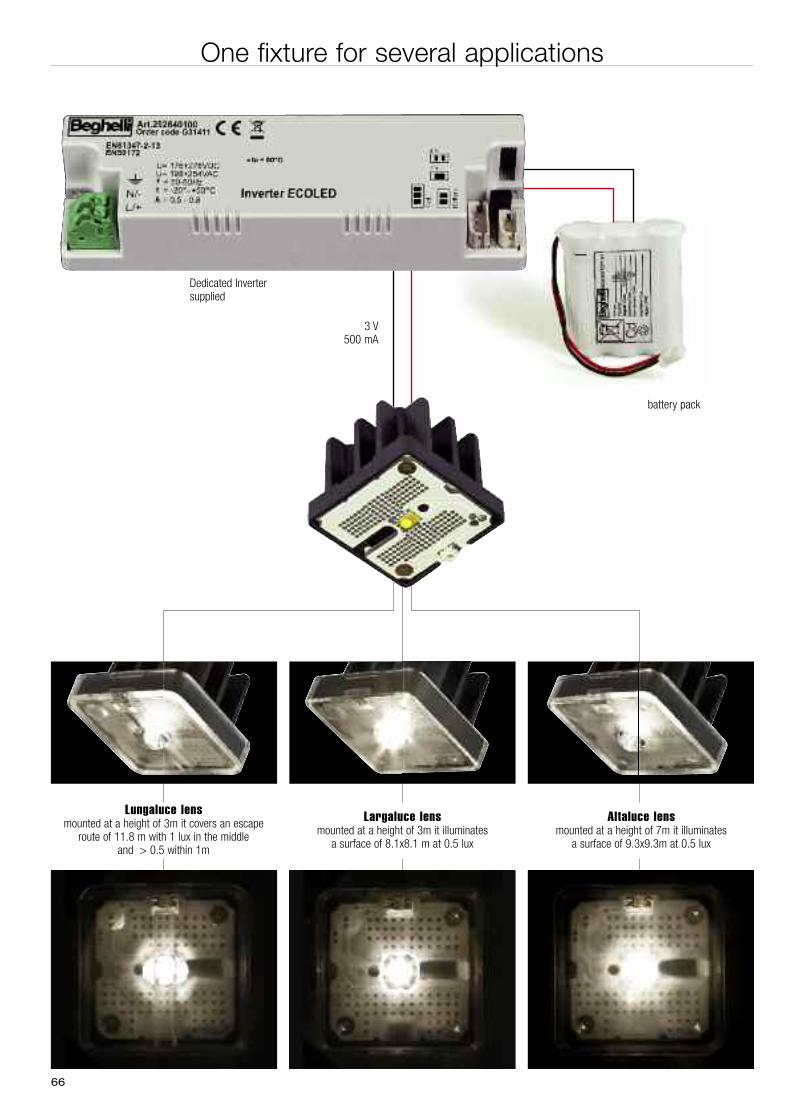
One fixture for several applications
Lungaluce lensmounted at a height of 3m it covers an escape
route of 11.8 m with 1 lux in the middle and > 0.5 within 1m
Largaluce lensmounted at a height of 3m it illuminates
a surface of 8.1x8.1 m at 0.5 lux
Altaluce lensmounted at a height of 7m it illuminates
a surface of 9.3x9.3m at 0.5 lux
Dedicated Invertersupplied
battery pack
3 V500 mA
67
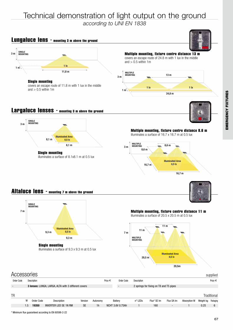
Technical demonstration of light output on the groundaccording to UNI EN 1838
3 m
11,8 m
1 lx1 m
SINGLEMOUNTING
3 m13 m
24,8 m
MULTIPLEMOUNTING
1 m1 lx 1 lx
9,3 m
9,3 m
7 m
Illuminated Area 0,5 lx
Illuminated Area 0,5 lx
Illuminated AreaIlluminated AreaIlluminated AreaIlluminated AreaIlluminated Area
SINGLEMOUNTING
20,5m
20,5 m
7 m11 m
11 m
Illuminated Area 0,5 lx
Illuminated Area 0,5 lx
Illuminated AreaIlluminated AreaIlluminated AreaIlluminated Area 0,5 lx
Illuminated Area 0,5 lx
Illuminated Area 0,5 lx 0,5 lx
Illuminated AreaIlluminated AreaIlluminated AreaIlluminated Area 0,5 lx 0,5 lx 0,5 lx
Illuminated AreaIlluminated AreaIlluminated AreaIlluminated Area 0,5 lx 0,5 lx
Illuminated Area 0,5 lx 0,5 lx 0,5 lx 0,5 lx
Illuminated Area 0,5 lx 0,5 lx 0,5 lx 0,5 lx 0,5 lx
Illuminated Area 0,5 lx
Illuminated Area 0,5 lx
MULTIPLEMOUNTING
8,1 m
8,1 m
3 mSINGLEMOUNTING
Illuminated Area 0,5 lx
16,7 m
16,7 m
3 m8,6 m
8,6 m
Illuminated Area 0,5 lx
MULTIPLEMOUNTING
Illuminated Area 0,5 lx 0,5 lx 0,5 lx 0,5 lx 0,5 lx 0,5 lx 0,5 lx 0,5 lx 0,5 lx 0,5 lx 0,5 lx
Illuminated Area
Single mountingcovers an escape route of 11.8 m with 1 lux in the middle and > 0.5 within 1m
Multiple mounting, fixture centre distance 13 mcovers an escape route of 24.8 m with 1 lux in the middle and > 0.5 within 1m
Lungaluce lens - mounting 3 m above the ground
Largaluce lenses - mounting 3 m above the ground
Single mountingilluminates a surface of 8.1x8.1 m at 0.5 lux
Multiple mounting, fixture centre distance 8.6 milluminates a surface of 16.7 x 16.7 m at 0.5 lux
Altaluce lens - mounting 7 m above the ground
Single mountingilluminates a surface of 9.3 x 9.3 m at 0.5 lux
Multiple mounting, fixture centre distance 11 milluminates a surface of 20.5 x 20.5 m at 0.5 lux
- 3 lenses: LUNGA, LARGA, ALTA with 3 different covers - 2 springs for fixing on T8 and T5 pipes
Accessories suppliedOrder Code Description Price € Order Code Description Price €
EM
ER
GE
NC
Y F
IXTU
RE
S
19350 INVERTER LED SE 1N RM SE 1h NCHT 3.6V 0.75Ah 1 160 - 1 0.25 6
Order Code Description Version Autonomy Battery n° LEDs Flux* SE lm Flux SA lm Absorption W Weight kg PackagingW
TR Traditional
1.5
* Minimum flux guaranteed according to EN 60598-2-22

6868
69
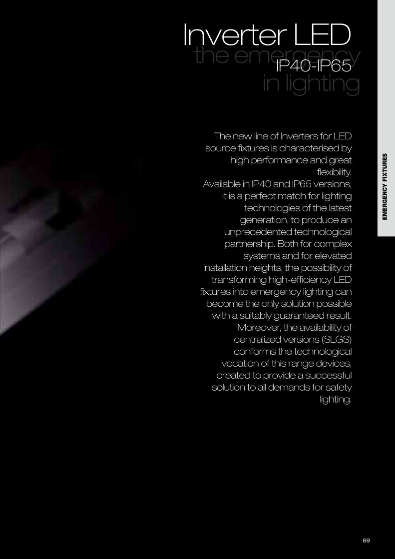
The new line of Inverters for LEDsource fixtures is characterised by
high performance and greatflexibility.
Available in IP40 and IP65 versions,it is a perfect match for lighting
technologies of the latestgeneration, to produce an
unprecedented technologicalpartnership. Both for complex
systems and for elevatedinstallation heights, the possibility oftransforming high-efficiency LED
fixtures into emergency lighting canbecome the only solution possiblewith a suitably guaranteed result.
Moreover, the availability ofcentralized versions (SLGS)conforms the technological
vocation of this range devices,created to provide a successfulsolution to all demands for safety
lighting.
the emergency in lighting
Inverter LEDIP40-IP65
69
EM
ER
GE
NC
Y F
IXTU
RE
S
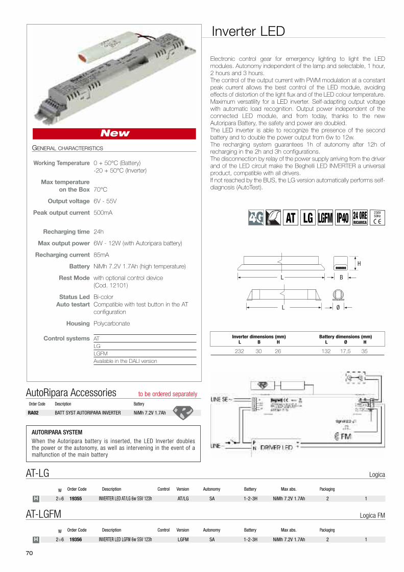
19356 INVERTER LED LGFM 6w 55V 123h LGFM SA 1-2-3H NiMh 7.2V 1.7Ah 2 12÷6
Order Code Description Control Version Autonomy Battery Max abs. PackagingW
AT-LGFM Logica FM
H
19355 INVERTER LED AT/LG 6w 55V 123h AT/LG SA 1-2-3H NiMh 7.2V 1.7Ah 2 12÷6
Order Code Description Control Version Autonomy Battery Max abs. PackagingW
AT-LG Logica
H
Inverter LED
Electronic control gear for emergency lighting to light the LEDmodules. Autonomy independent of the lamp and selectable, 1 hour,2 hours and 3 hours.The control of the output current with PWM modulation at a constantpeak current allows the best control of the LED module, avoidingeffects of distortion of the light flux and of the LED colour temperature.Maximum versatility for a LED inverter. Self-adapting output voltagewith automatic load recognition. Output power independent of theconnected LED module, and from today, thanks to the newAutoripara Battery, the safety and power are doubled.The LED inverter is able to recognize the presence of the secondbattery and to double the power output from 6w to 12w.The recharging system guarantees 1h of autonomy after 12h ofrecharging in the 2h and 3h configurations.The disconnection by relay of the power supply arriving from the driverand of the LED circuit make the Beghelli LED INVERTER a universalproduct, compatible with all drivers.If not reached by the BUS, the LG version automatically performs self-diagnosis (AutoTest).
GENERAL CHARACTERISTICS
Working Temperature 0 + 50°C (Battery)-20 + 50°C (Inverter)
Max temperature
on the Box 70°C
Output voltage 6V - 55V
Peak output current 500mA
Recharging time 24h
Max output power 6W - 12W (with Autoripara battery)
Recharging current 85mA
Battery NiMh 7.2V 1.7Ah (high temperature)
Rest Mode with optional control device(Cod. 12101)
Status Led Bi-colorAuto testart Compatible with test button in the AT
configuration
Housing Polycarbonate
Control systems ATLGLGFMAvailable in the DALI version
232 30 26 132 17,5 35
Inverter dimensions (mm) Battery dimensions (mm)L B H L Ø H
H
BL
ØL
New
70
RA02 BATT SYST AUTORIPARA INVERTER NiMh 7.2V 1.7Ah
AutoRipara Accessories to be ordered separatelyOrder Code Description Battery
AUTORIPARA SYSTEMWhen the Autoripara battery is inserted, the LED Inverter doublesthe power or the autonomy, as well as intervening in the event of amalfunction of the main battery
230V50HzLGAT IP40 24 ORE
RICARICALGFM

71
Inverter LED IP65
19365 INVERTER LED LGFM 6w 55V 123h LGFM SA 1-2-3H NiMh 7.2V 1.7Ah 2 12÷6
Order Code Description Control Version Autonomy Battery Max abs. PackagingW
AT-LGFM Logica FM
H
19364 INVERTER LED AT/LG 6w 55V 123h AT/LG SA 1-2-3H NiMh 7.2V 1.7Ah 2 12÷6
Order Code Description Control Version Autonomy Battery Max abs. PackagingW
AT-LG Logica
H
Electronic control gear for emergency lighting to light the LEDmodules. Autonomy independent of the lamp and selectable, 1 hour,2 hours and 3 hours.The control of the output current with PWM modulation at a constantpeak current allows the best control of the LED module, avoidingeffects of distortion of the light flux and of the LED colour temperature.Maximum versatility for a LED inverter. Self-adapting output voltagewith automatic load recognition. Output power independent of theconnected LED module, and from today, thanks to the newAutoripara Battery, the safety and power are doubled.The LED inverter is able to recognize the presence of the secondbattery and to double the power output from 6w to 12w.The recharging system guarantees 1h of autonomy after 12h ofrecharging in the 2h and 3h configurations.The disconnection by relay of the power supply arriving from the driverand of the LED circuit make the Beghelli LED INVERTER a universalproduct, compatible with all drivers.If not reached by the BUS, the LG version automatically performs self-diagnosis (AutoTest).
GENERAL CHARACTERISTICS
Working Temperature 0 + 50°C (Battery)-20 + 50°C (Inverter)
Max temperature
on the Box 70°C
Output voltage 6V - 55V
Peak output current 500mA
Recharging time 24h
Max output power 6W - 12W (with Autoripara battery)
Recharging current 85mA
Battery NiMh 7.2V 1.7Ah (high temperature)
Rest Mode with optional control device(Cod. 12101)
Status Led Bi-colorAuto testart Compatible with test button in the
AT configuration
Housing Extruded aluminium
Control systems ATLGLGFMAvailable in the DALI version
IP65
258 76 41
Inverter dimensions (mm)L B H
H
BL
New
230V50HzLGAT 24 HOURS
RECHARGELGFM EM
ER
GE
NC
Y F
IXTU
RE
S
RA02 BATT SYST AUTORIPARA INVERTER NiMh 7.2V 1.7Ah
AutoRipara Accessories to be ordered separatelyOrder Code Description Battery
AUTORIPARA SYSTEMWhen the Autoripara battery is inserted, the LED Inverter doublesthe power or the autonomy, as well as intervening in the event of amalfunction of the main battery
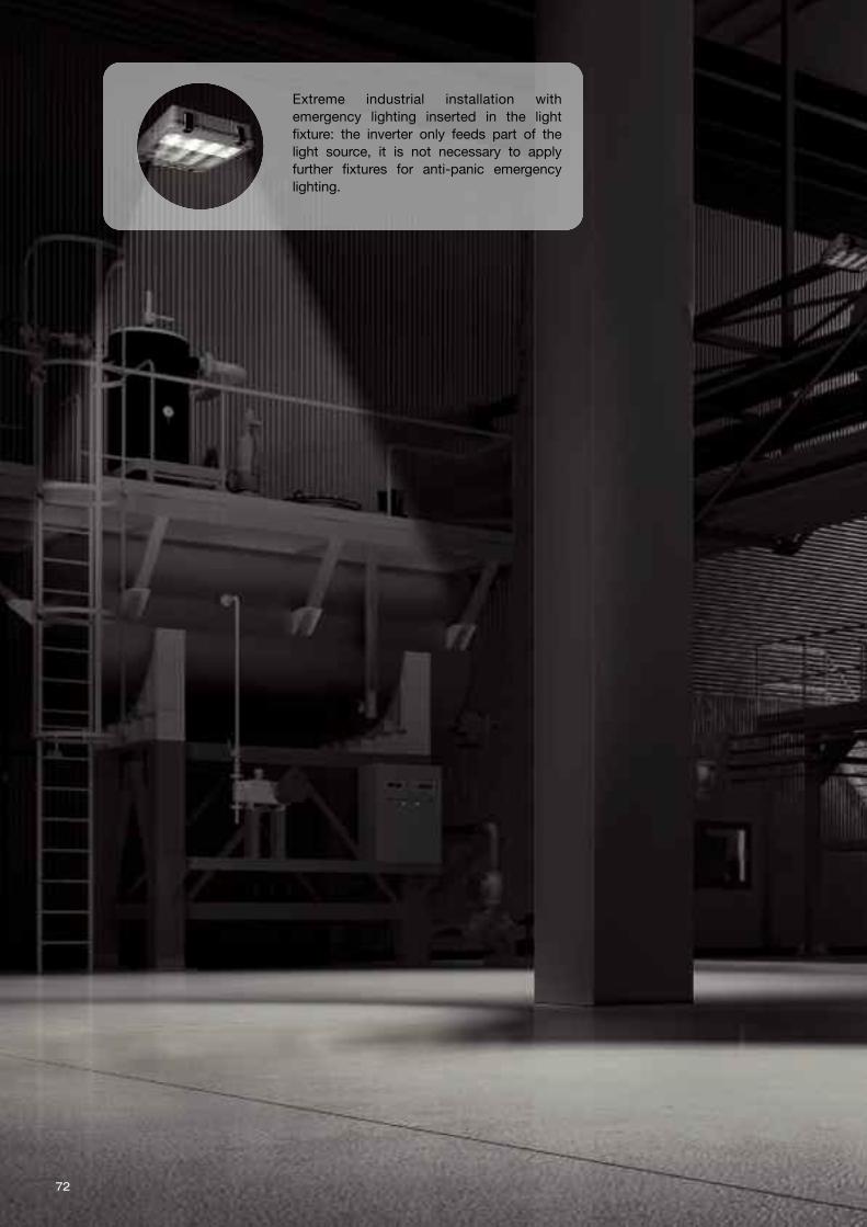
72
Extreme industrial installation withemergency lighting inserted in the lightfixture: the inverter only feeds part of thelight source, it is not necessary to applyfurther fixtures for anti-panic emergencylighting.
73
EM
ER
GE
NC
Y F
IXTU
RE
S
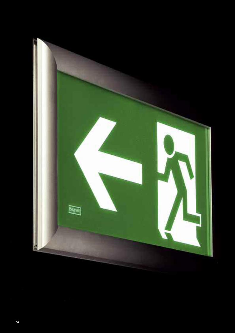
74
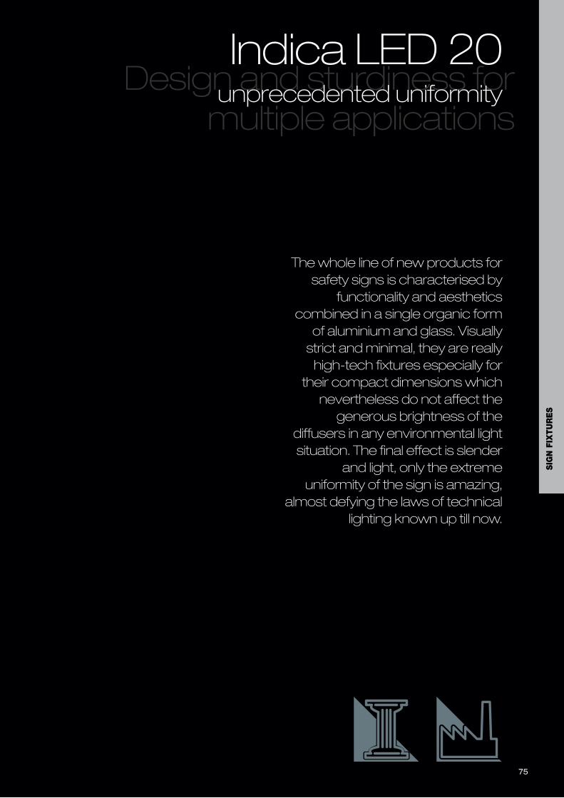
75
The whole line of new products forsafety signs is characterised by
functionality and aestheticscombined in a single organic formof aluminium and glass. Visuallystrict and minimal, they are reallyhigh-tech fixtures especially for
their compact dimensions whichnevertheless do not affect thegenerous brightness of the
diffusers in any environmental lightsituation. The final effect is slender
and light, only the extremeuniformity of the sign is amazing,
almost defying the laws of technicallighting known up till now.
Design and sturdiness formultiple applications
Indica LED 20unprecedented uniformity
SIG
N F
IXTU
RE
S

76
Indica LED is the design solution for sign lighting requirements, with ahigh technological content for all types of applications. A back lightsystem is used and, thanks to a patented optical system, itguarantees maximum uniformity of sign illumination with excellentluminosity. The fixture is also particularly versatile because it has auniversal bracket that can be fitted either on the long side, formounting on the ceiling, or on the long side for cantileveredapplications on the wall. A single-sided version is also available forabove-door installations. All Indica LED products have silk-screenprinted opaline polycarbonate diffusers for easier installation and toguarantee a very high sign illuminance uniformity (over 500cd/sq.m)on the white part.
Photometric diagrams and Luce Utile page 143, Symbols on cover,Spare batteries page 154
Indica LED 20mLED signs
GENERAL CHARACTERISTICS
Powers 1-2.1 W
Operation HT, Permanent (SA)/Public performance(PS) selectable with DIP switch inversions LG and LGFM
Standard EN 60598-1, EN 60598-2-2,EN 60598-2-22, UNI EN 1838,UNI 11222, DIN 4844-1, EN 62034
Protection grade IP40 single-sided version, IP41cantilevered version
Autonomy 1h, 2h, 3h selectable with DIP switch inthe LG and LGFM versions
Mounting wall, false ceiling, ceiling with rods,cantilevered on wall, cantilevered on ceiling,
Housing Aluminium frame and bracket inpolycarbonate RAL 7035
Optics high-efficiency back light system
B
L H
B
L H
B
L
H
L
B
H
Wall double-sided version Wall single-sided versionRecessed single-sided versionCeiling double-sided version
20 235 135 15
DV L B H
20 235 135 38
DV L B H20 266 252 36
DV L B H
20 235 166 36
DV L B H
19380 RODS 250MM INDICA DF
19381 RODS 500MM INDICA DF
19382 RODS 1000MM INDICA DF
19383 WIRE SUSPENSION 2MT INDICA DF
19384 FALSE CEILING RECESSED BRACKET 20M
Accessories to be ordered separatelyOrder Code Description
- DIFFUSER R/L/LOW
Accessories suppliedOrder Code Description
IP40IP41 AT LG SLG HT
850°C UVSLGS230V50Hz
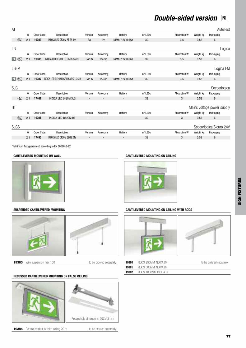
77777777
Double-sided version IP41
* Minimum flux guaranteed according to EN 60598-2-22
19305 INDICA LED DF20M LG SA/PS 1/2/3H SA/PS 1/2/3h NiMh 7.2V 0.6Ah 32 3.5 0.52 6
Order Code Description Version Autonomy Battery n° LEDs Absorption W Weight kg PackagingW
LG Logica
2.1
19303 INDICA LED DF20M AT SA 1/H SA 1/h NiMh 7.2V 0.6Ah 32 3.5 0,52 6
Order Code Description Version Autonomy Battery n° LEDs Absorption W Weight kg PackagingW
AT AutoTest
2.1
19307 INDICA LED DF20M LGFM SA/PS 1/2/3H SA/PS 1/2/3h NiMh 7.2V 0.6Ah 32 3.5 0.52 6
Order Code Description Version Autonomy Battery n° LEDs Absorption W Weight kg PackagingW
LGFM Logica FM
2.1
17461 INDICA LED DF20M SLG - - - 32 3 0.52 6
Order Code Description Version Autonomy Battery n° LEDs Absorption W Weight kg PackagingW
SLG Soccorlogica
2.1
17495 INDICA LED DF20M SLGS 24V - - - 32 3 0.52 6
Order Code Description Version Autonomy Battery n° LEDs Absorption W Weight kg PackagingW
SLGS Soccorlogica Sicuro 24V
2.1
19301 INDICA LED DF20M HT - - - 32 3 0.52 6
Order Code Description Version Autonomy Battery n° LEDs Absorption W Weight kg PackagingW
HT Mains voltage power supply
2.1
19383 Wire suspension max 100 to be ordered separately
SUSPENDED CANTILEVERED MOUNTING
19384 Recess bracket for false ceiling 20 m to be ordered separately
RECESSED CANTILEVERED MOUNTING ON FALSE CEILING
CANTILEVERED MOUNTING ON CEILING
19380 RODS 250MM INDICA DF to be ordered separately
19381 RODS 500MM INDICA DF
19382 RODS 1000MM INDICA DF
CANTILEVERED MOUNTING ON CEILING WITH RODS
CANTILEVERED MOUNTING ON WALL
Recess hole dimensions: 297x43 mm
H
H
SIG
N F
IXTU
RE
S
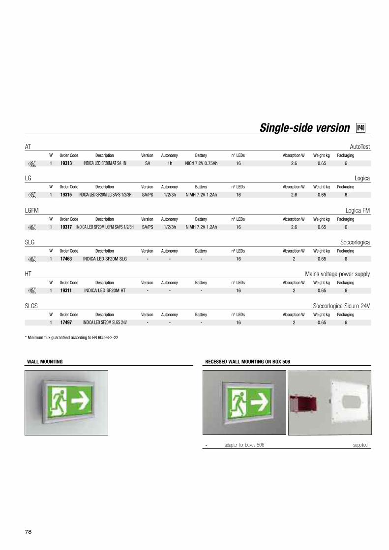
78
WALL MOUNTING
Single-side version IP40
* Minimum flux guaranteed according to EN 60598-2-22
19315 INDICA LED SF20M LG SAPS 1/2/3H SA/PS 1/2/3h NiMH 7.2V 1.2Ah 16 2.6 0.65 6
Order Code Description Version Autonomy Battery n° LEDs Absorption W Weight kg PackagingW
LG Logica
1
19313 INDICA LED SF20M AT SA 1N SA 1h NiCd 7.2V 0.75Ah 16 2.6 0.65 6
Order Code Description Version Autonomy Battery n° LEDs Absorption W Weight kg PackagingW
AT AutoTest
1
19317 INDICA LED SF20M LGFM SAPS 1/2/3H SA/PS 1/2/3h NiMH 7.2V 1.2Ah 16 2.6 0.65 6
Order Code Description Version Autonomy Battery n° LEDs Absorption W Weight kg PackagingW
LGFM Logica FM
1
17463 INDICA LED SF20M SLG - - - 16 2 0.65 6
Order Code Description Version Autonomy Battery n° LEDs Absorption W Weight kg PackagingW
SLG Soccorlogica
1
19311 INDICA LED SF20M HT - - - 16 2 0.65 6
Order Code Description Version Autonomy Battery n° LEDs Absorption W Weight kg PackagingW
HT Mains voltage power supply
1
- adapter for boxes 506 supplied
RECESSED WALL MOUNTING ON BOX 506
17497 INDICA LED SF20M SLGS 24V - - - 16 2 0.65 6
Order Code Description Version Autonomy Battery n° LEDs Absorption W Weight kg PackagingW
SLGS Soccorlogica Sicuro 24V
1
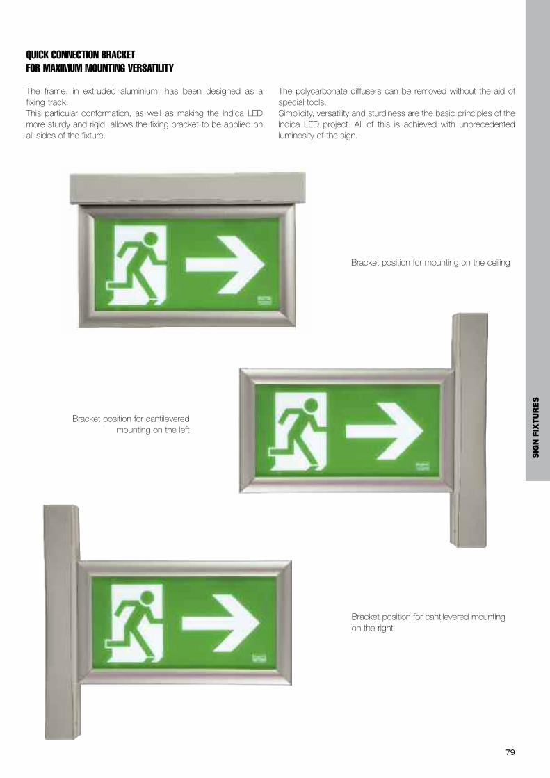
79
QUICK CONNECTION BRACKET FOR MAXIMUM MOUNTING VERSATILITY
The frame, in extruded aluminium, has been designed as afixing track.This particular conformation, as well as making the Indica LEDmore sturdy and rigid, allows the fixing bracket to be applied onall sides of the fixture.
The polycarbonate diffusers can be removed without the aid ofspecial tools.Simplicity, versatility and sturdiness are the basic principles of theIndica LED project. All of this is achieved with unprecedentedluminosity of the sign.
Bracket position for cantilevered mounting on the left
Bracket position for mounting on the ceiling
Bracket position for cantilevered mountingon the right
SIG
N F
IXTU
RE
S
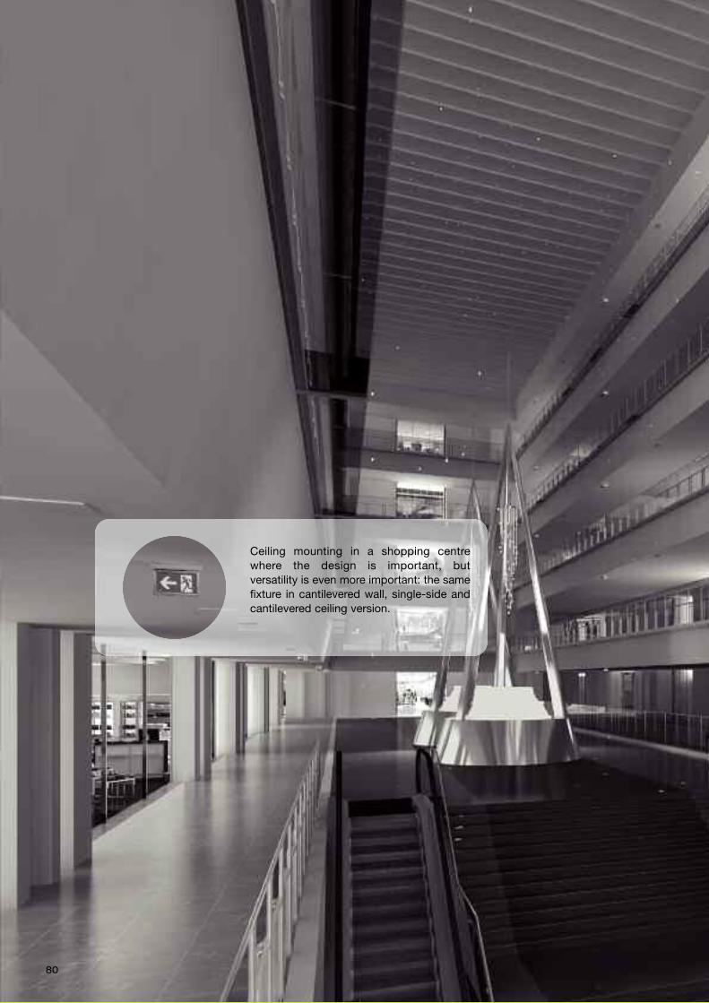
80
Ceiling mounting in a shopping centrewhere the design is important, butversatility is even more important: the samefixture in cantilevered wall, single-side andcantilevered ceiling version.
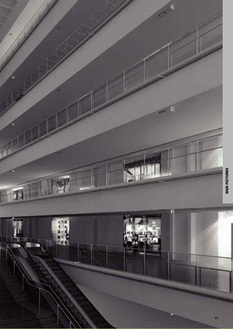
81
SIG
N F
IXTU
RE
S
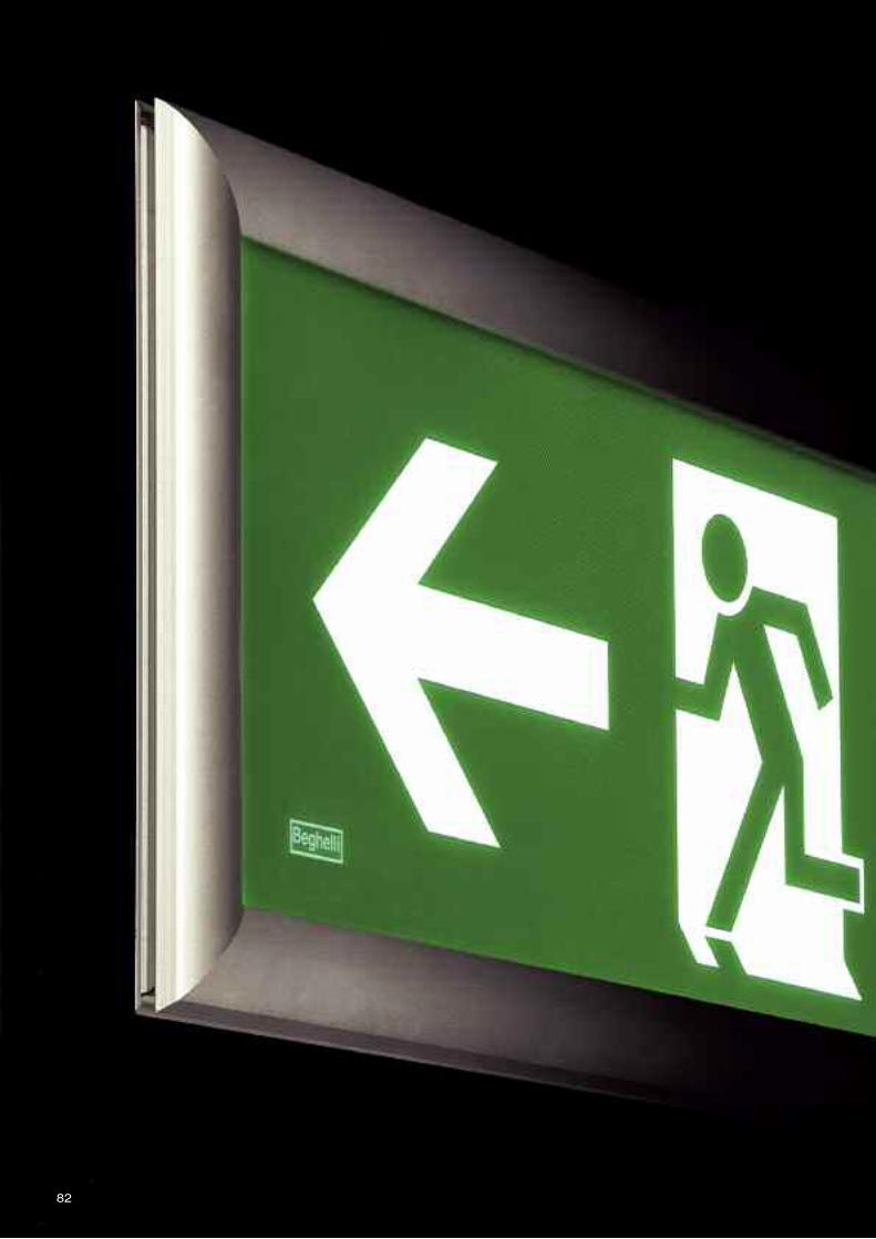
82
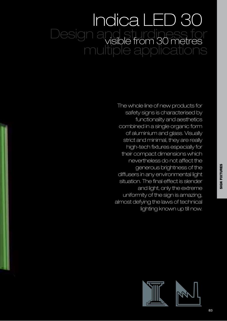
The whole line of new products forsafety signs is characterised by
functionality and aestheticscombined in a single organic formof aluminium and glass. Visuallystrict and minimal, they are reallyhigh-tech fixtures especially for
their compact dimensions whichnevertheless do not affect thegenerous brightness of the
diffusers in any environmental lightsituation. The final effect is slender
and light, only the extremeuniformity of the sign is amazing,
almost defying the laws of technicallighting known up till now.
Design and sturdiness formultiple applications
Indica LED 30visible from 30 metres
83
SIG
N F
IXTU
RE
S
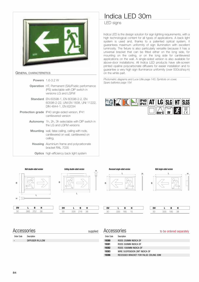
84
Indica LED is the design solution for sign lighting requirements, with ahigh technological content for all types of applications. A back lightsystem is used and, thanks to a patented optical system, itguarantees maximum uniformity of sign illumination with excellentluminosity. The fixture is also particularly versatile because it has auniversal bracket that can be fitted either on the long side, formounting on the ceiling, or on the long side for cantileveredapplications on the wall. A single-sided version is also available forabove-door installations. All Indica LED products have silk-screenprinted opaline polycarbonate diffusers for easier installation and toguarantee a very high sign illuminance uniformity (over 500cd/sq.m)on the white part.
Photometric diagrams and Luce Utile page 143, Symbols on cover,Spare batteries page 154
Indica LED 30mLED signs
GENERAL CHARACTERISTICS
Powers 1.6-3.2 W
Operation HT, Permanent (SA)/Public performance(PS) selectable with DIP switch inversions LG and LGFM
Standard EN 60598-1, EN 60598-2-2, EN60598-2-22, UNI EN 1838, UNI 11222,DIN 4844-1, EN 62034
Protection grade IP40 single-sided version, IP41cantilevered version
Autonomy 1h, 2h, 3h selectable with DIP switch inthe LG and LGFM versions
Mounting wall, false ceiling, ceiling with rods,cantilevered on wall, cantilevered onceiling,
Housing Aluminium frame and polycarbonatebracket RAL 7035
Optics high-efficiency back light system
19380 RODS 250MM INDICA DF
19381 RODS 500MM INDICA DF
19382 RODS 1000MM INDICA DF
19383 WIRE SUSPENSION 2MT INDICA DF
19386 RECESSED BRACKET FOR FALSE CEILING 30M
Accessories to be ordered separatelyOrder Code Description
- DIFFUSER R/L/LOW
Accessories suppliedOrder Code Description
B
L H
B
L H
B
L
H
L
B
H
Wall double-sided version Wall single-sided versionRecessed single-sided versionCeiling double-sided version
30 335 185 15
DV L B H
30 335 185 38
DV L B H30 366 252 36
DV L B H
30 335 216 36
DV L B H
IP40IP41 AT LG SLG HT
850°C UV
SLGS230V50Hz
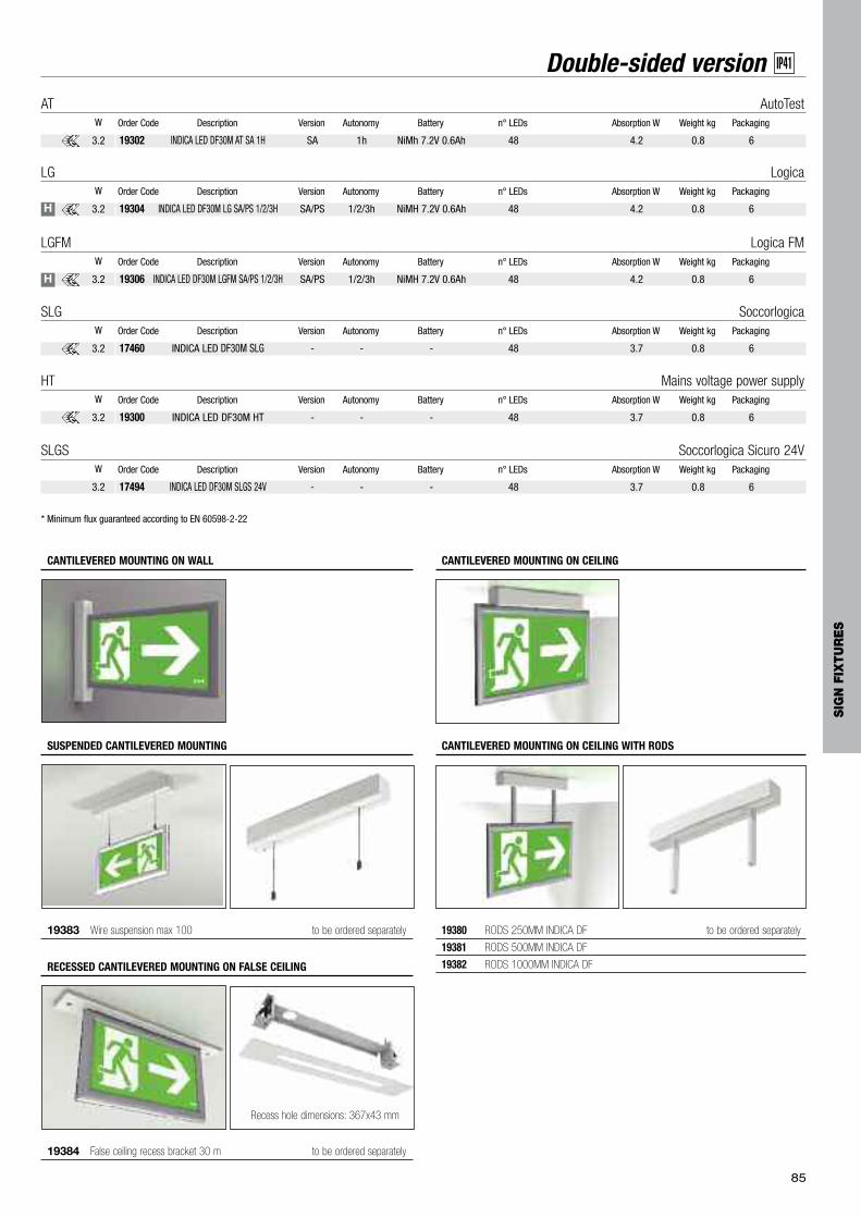
85
Double-sided version IP41
* Minimum flux guaranteed according to EN 60598-2-22
19304 INDICA LED DF30M LG SA/PS 1/2/3H SA/PS 1/2/3h NiMH 7.2V 0.6Ah 48 4.2 0.8 6
Order Code Description Version Autonomy Battery n° LEDs Absorption W Weight kg PackagingW
LG Logica
3.2
19302 INDICA LED DF30M AT SA 1H SA 1h NiMh 7.2V 0.6Ah 48 4.2 0.8 6
Order Code Description Version Autonomy Battery n° LEDs Absorption W Weight kg PackagingW
AT AutoTest
3.2
19306 INDICA LED DF30M LGFM SA/PS 1/2/3H SA/PS 1/2/3h NiMH 7.2V 0.6Ah 48 4.2 0.8 6
Order Code Description Version Autonomy Battery n° LEDs Absorption W Weight kg PackagingW
LGFM Logica FM
3.2
17460 INDICA LED DF30M SLG - - - 48 3.7 0.8 6
Order Code Description Version Autonomy Battery n° LEDs Absorption W Weight kg PackagingW
SLG Soccorlogica
3.2
19300 INDICA LED DF30M HT - - - 48 3.7 0.8 6
Order Code Description Version Autonomy Battery n° LEDs Absorption W Weight kg PackagingW
HT Mains voltage power supply
3.2
CANTILEVERED MOUNTING ON WALL CANTILEVERED MOUNTING ON CEILING
19380 RODS 250MM INDICA DF to be ordered separately
19381 RODS 500MM INDICA DF
19382 RODS 1000MM INDICA DF
CANTILEVERED MOUNTING ON CEILING WITH RODS
19383 Wire suspension max 100 to be ordered separately
SUSPENDED CANTILEVERED MOUNTING
19384 False ceiling recess bracket 30 m to be ordered separately
RECESSED CANTILEVERED MOUNTING ON FALSE CEILING
Recess hole dimensions: 367x43 mm
H
H
17494 INDICA LED DF30M SLGS 24V - - - 48 3.7 0.8 6
Order Code Description Version Autonomy Battery n° LEDs Absorption W Weight kg PackagingW
SLGS Soccorlogica Sicuro 24V
3.2
SIG
N F
IXTU
RE
S
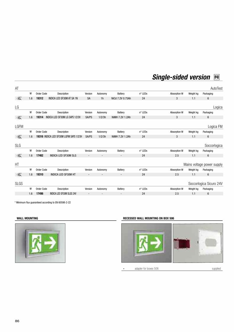
86
WALL MOUNTING
Single-sided version IP40
19314 INDICA LED SF30M LG SAPS 1/2/3H SA/PS 1/2/3h NiMH 7.2V 1.2Ah 24 3 1.1 6
Order Code Description Version Autonomy Battery n° LEDs Absorption W Weight kg PackagingW
LG Logica
1.6
19312 INDICA LED SF30M AT SA 1N SA 1h NiCd 7.2V 0.75Ah 24 3 1.1 6
Order Code Description Version Autonomy Battery n° LEDs Absorption W Weight kg PackagingW
AT AutoTest
1.6
19316 INDICA LED SF30M LGFM SAPS 1/2/3H SA/PS 1/2/3h NiMH 7.2V 1.2Ah 24 3 1.1 6
Order Code Description Version Autonomy Battery n° LEDs Absorption W Weight kg PackagingW
LGFM Logica FM
1.6
17462 INDICA LED SF30M SLG - - - 24 2.5 1.1 6
Order Code Description Version Autonomy Battery n° LEDs Absorption W Weight kg PackagingW
SLG Soccorlogica
1.6
19310 INDICA LED SF30M HT - - - 24 2.5 1.1 6
Order Code Description Version Autonomy Battery n° LEDs Absorption W Weight kg PackagingW
HT Mains voltage power supply
1.6
* Minimum flux guaranteed according to EN 60598-2-22
- adapter for boxes 506 supplied
RECESSED WALL MOUNTING ON BOX 506
17496 INDICA LED SF30M SLGS 24V - - - 24 2.5 1.1 6
Order Code Description Version Autonomy Battery n° LEDs Absorption W Weight kg PackagingW
SLGS Soccorlogica Sicuro 24V
1.6
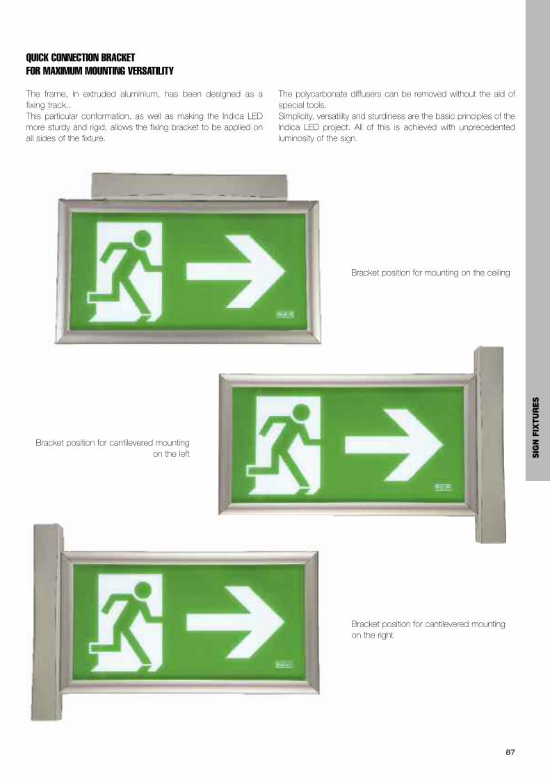
87
QUICK CONNECTION BRACKET FOR MAXIMUM MOUNTING VERSATILITY
The frame, in extruded aluminium, has been designed as afixing track..This particular conformation, as well as making the Indica LEDmore sturdy and rigid, allows the fixing bracket to be applied onall sides of the fixture.
The polycarbonate diffusers can be removed without the aid ofspecial tools.Simplicity, versatility and sturdiness are the basic principles of theIndica LED project. All of this is achieved with unprecedentedluminosity of the sign.
Bracket position for cantilevered mountingon the left
Bracket position for mounting on the ceiling
Bracket position for cantilevered mountingon the right
SIG
N F
IXTU
RE
S

88
Cantilevered mounting in a conferencecentre where the spaces require highvisibility distances (30m)
89
SIG
N F
IXTU
RE
S
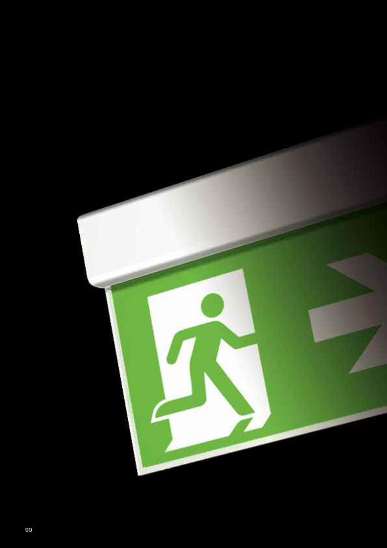
90
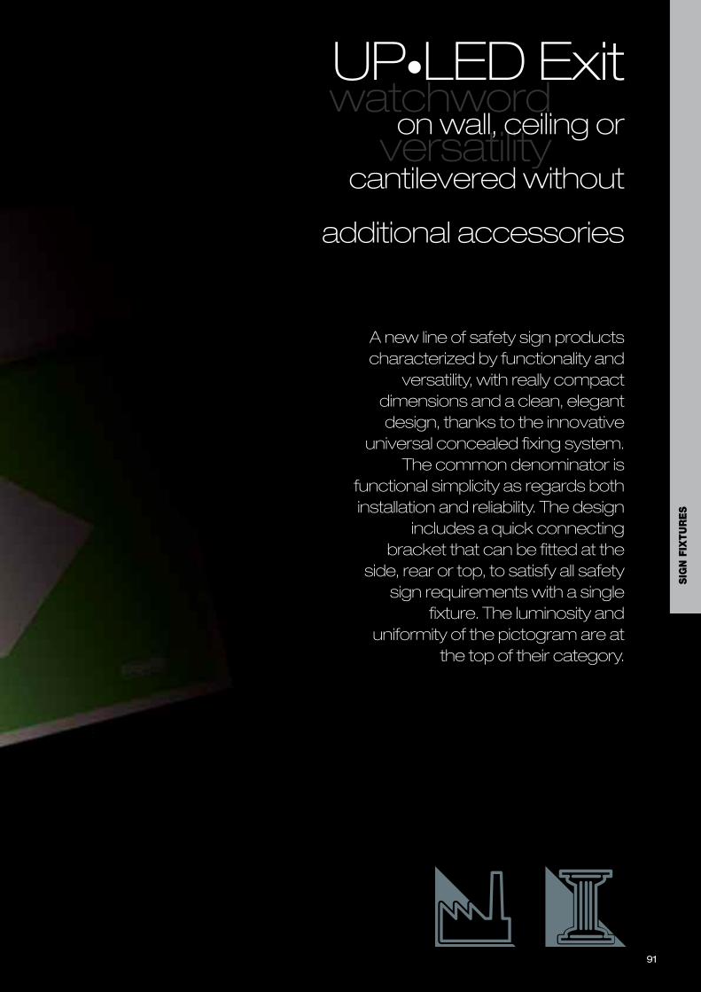
91
A new line of safety sign productscharacterized by functionality and
versatility, with really compactdimensions and a clean, elegantdesign, thanks to the innovative
universal concealed fixing system. The common denominator is
functional simplicity as regards bothinstallation and reliability. The design
includes a quick connectingbracket that can be fitted at the
side, rear or top, to satisfy all safetysign requirements with a single
fixture. The luminosity anduniformity of the pictogram are at
the top of their category.
watchwordversatility
UP•LED Exiton wall, ceiling or
cantilevered without
additional accessories
SIG
N F
IXTU
RE
S
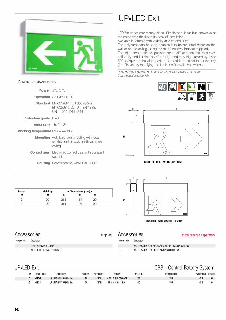
LH
B
B
H L
9292
UP•LED Exit
LED fixture for emergency signs. Simple and linear but innovative atthe same time thanks to its easy of installation . Available in formats with visibility at 20m and 30m.The polycarbonate housing enables it to be mounted either on thewall or on the ceiling, using the multifunctional bracket supplied.The silk-screen printed polycarbonate diffuser ensures maximumuniformity and illumination of the sign and very high luminosity (over500cd/sq.m on the white part). It is possible to select the autonomy(1h, 2h, 3h) by modifying the luminous flux with the switches.
Photometric diagrams and Luce Utile page 143, Symbols on cover,Spare batteries page 154
GENERAL CHARACTERISTICS
Power 2W, 3 W
Operation SA INIBIT (RM)
Standard EN 60598-1, EN 60598-2-2,EN 60598-2-22, UNI EN 1838,UNI 11222, DIN 4844-1
Protection grade IP40
Autonomy 1h, 2h, 3h
Working temperature 0°C ÷ +40°C
Mounting wall, false ceiling, ceiling with rods,cantilevered on wall, cantilevered onceiling
Control gear Electronic control gear with constantcurrent
Housing Polycarbonate, white RAL 9003
Power visibility • Dimensions (mm) •W m L B H
2 20 214 154 293 30 314 194 29
- ACCESSORY FOR RECESSED MOUNTING ON CEILING
- ACCESSORY FOR SUSPENSION WITH RODS
Accessories to be ordered separatelyOrder Code Description
- DIFFUSERS R, L, LOW
- MULTIFUNCTIONAL BRACKET
Accessories suppliedOrder Code Description
4320 UP LED EXIT DF20M SA SA 1/2/3h NiMh 3.6V 750mAh 26 2.5 0.3 6
4321 UP LED EXIT DF30M SA SA 1/2/3h NiMh 3.6V 1.5Ah 40 3.5 0.5 6
Order Code Description Version Autonomy Battery n° LEDs Absorption W Weight kg PackagingW
UP•LED Exit CBS - Control Battery System
2
3
IP40850°C UV
SIGN DIFFUSER VISIBILITY 30M
SIGN DIFFUSER VISIBILITY 20M
230V50Hz
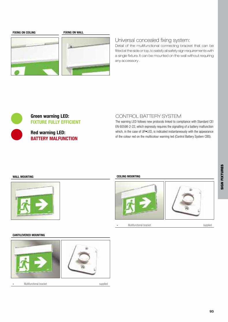
9393
Universal concealed fixing system:Detail of the multifunctional connecting bracket that can befitted at the side or top, to satisfy all safety sign requirements witha single fixture. It can be mounted on the wall without requiringany accessory .
WALL MOUNTING
- Multifunctional bracket supplied
CEILING MOUNTING
FIXING ON CEILING FIXING ON WALL
- Multifunctional bracket supplied
CANTILEVERED MOUNTING
CONTROL BATTERY SYSTEMThe warning LED follows new protocols linked to compliance with Standard CEI
EN 60598-2-22, which expressly requires the signalling of a battery malfunction
which, in the case of UP•LED, is indicated instantaneously with the appearance
of the colour red on the multicolour warning led (Control Battery System CBS).Red warning LED: BATTERY MALFUNCTION
Green warning LED: FIXTURE FULLY EFFICIENT
SIG
N F
IXTU
RE
S

94
UP•LED EXITCantilevered mounting with a sober andelegant appearance. With the practicalbracket supplied it can also be positionedon the wall or on the ceiling.
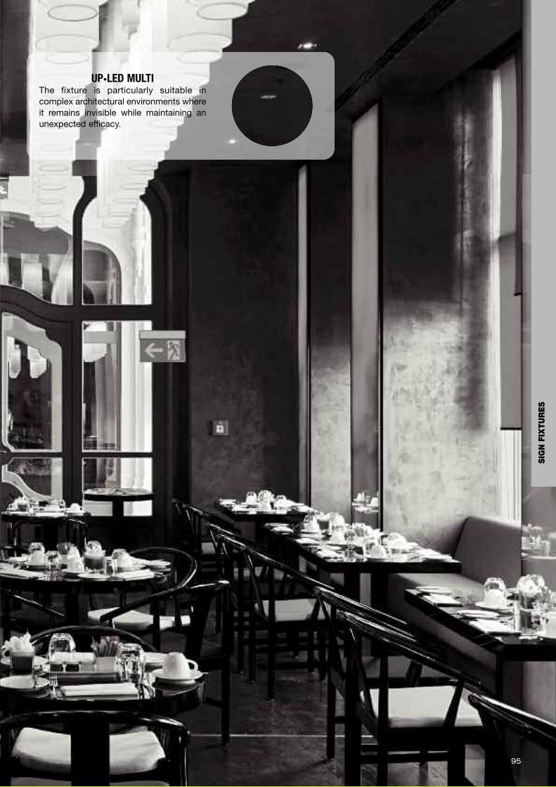
95
UP•LED MULTIThe fixture is particularly suitable incomplex architectural environments whereit remains invisible while maintaining anunexpected efficacy.
SIG
N F
IXTU
RE
S
9696
Technicalannex
Design 98
Control systemsAT - AutoTest 100
AR - AutoTest Ripara 100
LGFM - Logica FM 101
LG - Logica 102
SLG - Soccorlogica 103
SLGS - Soccorlogica Sicuro 24V 109
Examples of mounting
Local control AT 114
Centralized control LG-LGFM-SLG-SLGS 116
The Academy forprofessionals 118
Photometric diagrams and Luce Utile 119
9797
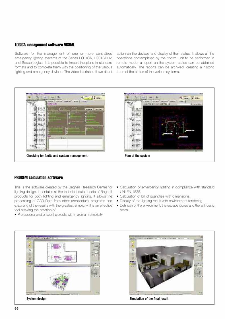
Simulation of the final result
98
Design
PROGEM calculation software
This is the software created by the Beghelli Research Centre forlighting design. It contains all the technical data sheets of Beghelliproducts for both lighting and emergency lighting. It allows theprocessing of CAD Data from other architectural programs andexporting of the results with the greatest simplicity. It is an effectivetool allowing the creation of:• Professional and efficient projects with maximum simplicity
• Calculation of emergency lighting in compliance with standardUNI-EN 1838.
• Calculation of bill of quantities with dimensions• Display of the lighting result with environment rendering• Definition of the environment, the escape routes and the anti-panicareas
System design
Plan of the systemChecking for faults and system management
LOGICA management software VISUAL
Software for the management of one or more centralizedemergency lighting systems of the Series LOGICA, LOGICA FMand SoccorLogica. It is possible to import the plans in standardformats and to complete them with the positioning of the variouslighting and emergency devices. The video interface allows direct
action on the devices and display of their status. It allows all theoperations contemplated by the control unit to be performed inremote mode: a report on the system status can be obtainedautomatically. The reports can be archived, creating a historictrace of the status of the various systems.
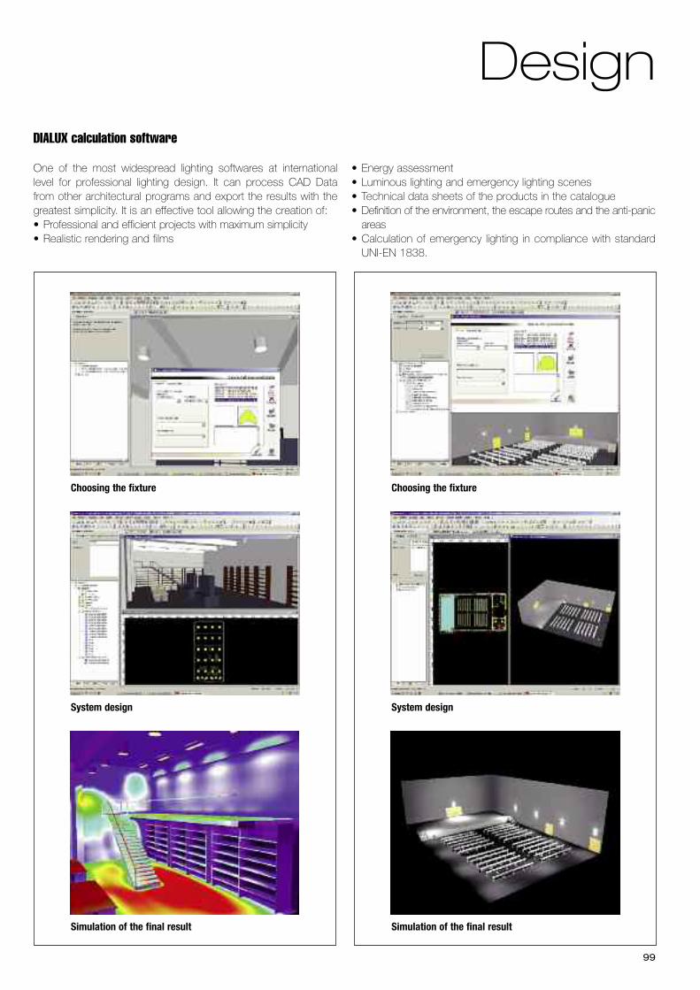
99
DIALUX calculation software
One of the most widespread lighting softwares at internationallevel for professional lighting design. It can process CAD Datafrom other architectural programs and export the results with thegreatest simplicity. It is an effective tool allowing the creation of:• Professional and efficient projects with maximum simplicity • Realistic rendering and films
• Energy assessment• Luminous lighting and emergency lighting scenes• Technical data sheets of the products in the catalogue• Definition of the environment, the escape routes and the anti-panicareas
• Calculation of emergency lighting in compliance with standardUNI-EN 1838.
Choosing the fixture
System design
Simulation of the final result
Choosing the fixture
System design
Simulation of the final result
Design
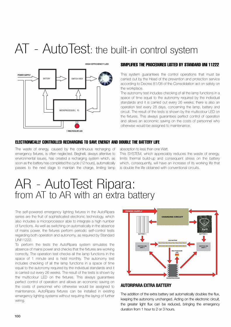
100
AT - AutoTest: the built-in control system
ELECTRONICALLY CONTROLLED RECHARGING TO SAVE ENERGY AND DOUBLE THE BATTERY LIFEThe waste of energy, caused by the continuous recharging ofemergency fixtures, is often neglected. Beghelli, always attentive toenvironmental issues, has created a recharging system which, assoon as the battery has completed the cycle (12 hours), automaticallypasses to the next stage to maintain the charge, limiting lamp
absorption to less than one Watt.This SYSTEM, which appreciably reduces the waste of energy,limits thermal build-up and consequent stress on the batterywhich, consequently, will have an increase of its working life thatis double the life obtained with conventional circuits.
SIMPLIFIES THE PROCEDURES LISTED BY STANDARD UNI 11222
This system guarantees the control operations that must becarried out by the Head of the prevention and protection serviceaccording to Decree 81/08 of the Consolidation act on safety onthe workplace. The autonomy test includes checking of all the lamp functions in aspace of time equal to the autonomy required by the individualstandards and it is carried out every 26 weeks; there is also anoperation test every 28 days, concerning the lamp, battery andcircuit. The result of the tests is shown by the multicolour LED onthe fixtures. This always guarantees perfect control of operationand allows an economic saving on the costs of personnel whootherwise would be assigned to maintenance.
POWER SUPPLY
HIGH EFFICIENCY LED
1 MULTICOLOR LED
BATTERY SWITCH-OVER
MICROPROCESSOR (m P)
AR - AutoTest Ripara:from AT to AR with an extra battery
The self-powered emergency lighting fixtures in the AutoRiparaseries are the fruit of sophisticated electronic technology, whichalso includes a microprocessor able to integrate a high numberof functions. As well as switching on automatically in the absenceof mains power, the fixtures perform periodic self-control testsregarding both operation and autonomy, as required by StandardUNI11222. To perform the tests the AutoRipara system simulates theabsence of mains power and checks that the fixtures are workingcorrectly. The operation test checks all the lamp functions in thespace of 1 minute and is held monthly. The autonomy testincludes checking of all the lamp functions in a space of timeequal to the autonomy required by the individual standards and itis carried out every 26 weeks. The result of the tests is shown bythe multicolour LED on the fixtures. This always guaranteesperfect control of operation and allows an economic saving onthe costs of personnel who otherwise would be assigned tomaintenance. AutoRipara fixtures can be installed in existingemergency lighting systems without requiring the laying of furtherwiring.
Control systems
SWITCH-ON UNIT 1
SWITCH-ON UNIT 2
CHARGING CIRCUIT
BATTERY 2BATTERY 1
LED MATRIX
MICROPROCESSOR
MULTICOLOURLED
POWER SUPPLY
AUTORIPARA EXTRA BATTERY
The addition of the extra battery set automatically doubles the flux,keeping the autonomy unchanged. Acting on the electronic circuit,the greater light flux can be reduced, bringing the emergencyduration from 1 hour to 2 or 3 hours.
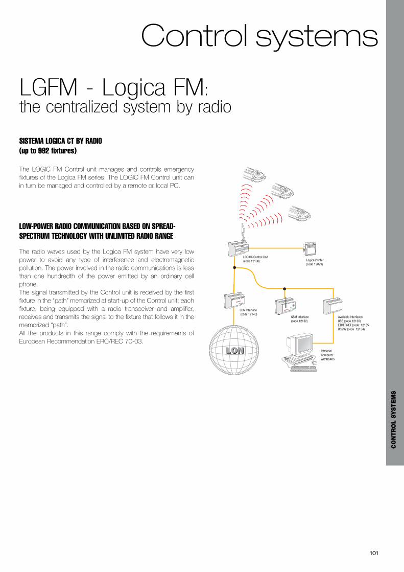
101
LGFM - Logica FM:the centralized system by radio
SISTEMA LOGICA CT BY RADIO (up to 992 fixtures)
The LOGIC FM Control unit manages and controls emergencyfixtures of the Logica FM series. The LOGIC FM Control unit canin turn be managed and controlled by a remote or local PC.
LOW-POWER RADIO COMMUNICATION BASED ON SPREAD-SPECTRUM TECHNOLOGY WITH UNLIMITED RADIO RANGE
The radio waves used by the Logica FM system have very lowpower to avoid any type of interference and electromagneticpollution. The power involved in the radio communications is lessthan one hundredth of the power emitted by an ordinary cellphone. The signal transmitted by the Control unit is received by the firstfixture in the “path” memorized at start-up of the Control unit; eachfixture, being equipped with a radio transceiver and amplifier,receives and transmits the signal to the fixture that follows it in thememorized “path”.All the products in this range comply with the requirements ofEuropean Recommendation ERC/REC 70-03.
Esc ok
LONLON PersonalComputerwithRS485
Logica Printer(code 12099)
Available Interfaces:USB (code 12136) ETHERNET (code 12135)RS232 (code 12134)
GSM Interface (code 12132)
LON Interface (code 12140)
LOGICA Control Unit(code 12100)
Control systems
CO
NTR
OL
SYSTE
MS

102
LG - Logica:the multifunctional centralized system
AUTOMATES THE PROCEDURES LISTEDBY STANDARD UNI 11222
LOGICA is a versatile and modular emergency control system,conceived to ensure compatibility with local and nationalregulations concerning the use and checking of emergencylighting systems. In particular Standard 11222 specifies the
procedures for the periodic checking, maintenance,
overhaul and commissioning of emergency fixtures.
- Modular system- Fixtures operating in both AutoTest and Centraltest mode- Programmable autonomy (1hour/ 3hours)- Performance of the test may be postponed for a part of thesystem (even / odd)
- Wired connections (LOGICA) or radio connections (LOGICAFM)
- DALI-compatible bus for management of DALI lighting fixtures(LOGICA)
- Possibility of remote control by PC (GSM interface, Ethernet,Usb, RS232)
- Possibility of integrations with Building Automation- Centralized configuration operations- 16 programmable groups of fixtures- 16 programmable luminosity scenes- Inverter (Power packs) for:- Incandescent lamps- Halogen lamps with electronic and magnetic transformers- Fluorescent tubes with electronic or magnetic ballast
The Logica Supervision Unit can manage up to 32 LOGICAControl units for a total of 4096 emergency lighting fixtures andDALI lighting fixtures. In turn it is possible to manage and controlthe LOGICA Supervision Unit by a remote or local PC.The LOGICA Supervision Unit adds the following functions to theLOGICA system:- Centralized programming and management of all the connectedLogica Control units
- Centralized printing of reports- Logbook (memorizing the results of the functional and autonomytests for two years)
LOGICA CT SYSTEM BY BUS (up to 128 fixtures)
The Logica Control unit allows management of both emergencyfixtures of the Logica series and DALI type lighting fixtures (DigitalAddressable Lighting Interface - International Standard accordingto Regulation IEC60929) up to a maximum of 128 fixtures.The number of Logica Control units that can be connected to aPC is practically unlimited, thus allowing the management andcontrol functions of countless devices to be grouped together ina single station.
Control unit Logica code 12100
up to 128
up to 128
up to 128
LOGICA Supervision Central Unit (cod. 12131)
Esc ok
PersonalComputerwith RS485
Logica Printer(cod. 12099)
Available interfaces:USB (cod. 12136) ETHERNET (cod. 12135)RS232 (cod. 12134)
GSM Interface(cod. 12132)
LON Interface (cod. 12140)
Esc ok
LOGICA Central Unit (cod. 12100)
Esc ok
LOGICA Central Unit(cod. 12100)
Esc ok
LOGICA Central Unit(cod. 12100)
LONLON
CENTRALIZED LOGICA SYSTEM VIA BUS THROUGH THE LOGICA SUPERVISION UNIT (up to 4096 fixtures)
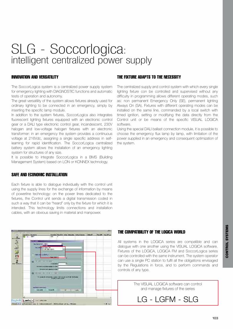
103
INNOVATION AND VERSATILITY
The SoccorLogica system is a centralized power supply systemfor emergency lighting with DIAGNOSTIC functions and automatictests of operation and autonomy. The great versatility of the system allows fixtures already used forordinary lighting to be connected in an emergency, simply byinserting the specific lamp module. In addition to the system fixtures, SoccorLogica also integratesfluorescent lighting fixtures equipped with an electronic controlgear or a DALI type electronic control gear, incandescent, 230Vhalogen and low-voltage halogen fixtures with an electronictransformer: in an emergency the system provides a continuousvoltage at 216Vdc, assigning a single specific address in self-learning for rapid identification. The SoccorLogica centralizedbattery system allows the installation of an emergency lightingsystem for structures of any size.It is possible to integrate SoccorLogica in a BMS (BuildingManagement System) based on LON or KONNEX technology.
SAFE AND ECONOMIC INSTALLATION
Each fixture is able to dialogue individually with the control unitusing the supply lines for the exchange of information by meansof powerline technology: on the power lines dedicated to thefixtures, the Control unit sends a digital transmission coded insuch a way that it can be “heard” only by the fixture for which it isintended. This technology limits connections and installationcables, with an obvious saving in material and manpower.
THE FIXTURE ADAPTS TO THE NECESSITY
The centralized supply and control system with which every singlelighting fixture con be controlled and supervised without anydifficulty in programming allows different operating modes, suchas: non permanent Emergency Only (SE), permanent lightingAlways On (SA). Fixtures with different operating modes can beinstalled on the same line, commanded by a local switch withtimed ignition, setting or modifying the data directly from theControl unit or be means of the specific VISUAL LOGICAsoftware.Using the special DALI ballast connection module, it is possible tochoose the emergency flux lamp by lamp, with limitation of thepower supplied in an emergency and consequent optimization ofthe system.
THE COMPATIBILITY OF THE LOGICA WORLD
All systems in the LOGICA series are compatible and candialogue with one another using the VISUAL LOGICA software.Fixtures of the LOGICA, LOGICA FM and SoccorLogica seriescan be controlled with the same instrument. The system operatorcan use a single PC station to fulfil all the obligations envisagedby the Regulations in force, and to perform commands andcontrols of any type.
The VISUAL LOGICA software can control and manage fixtures of the series
LG - LGFM - SLG
SLG - Soccorlogica: intelligent centralized power supply
CO
NTR
OL
SYSTE
MS

104
• The SoccorLogica Plus Control unit has a control board with alarge display panel and a separable frame for 19” rack moduleswith battery pack in a separate cabinet.
• The SoccorLogica Control unit has a control board with adisplay window and a fixed frame for 19” rack modules. Thebattery packs are housed directly in the bottom of the Controlunit cabinet.
FACILITATED DESIGN
To facilitate the designer’s and the installer’s job in sizing theSoccorLogica, a simple configurator is available which alsochecks the number of fixtures and the power per line.
THE CONTROL UNITS
The system Control unit is integrated in a metal cabinet thatcontains all the system components. In systems with higherpowers there is a second cabinet containing the battery packs.The batteries used are 216 V packs with an average life of morethan 10 years.Each control unit has a variable number of lineS, depending onthe model.Each output module manages 2 lines able to control up to 32fixtures for a maximum of 690W each line. The total must notexceed the total power of the Control unit.
The possibility of sharing the emergency lighting power supplyover several outputs, all individually protective and selectiveamong one another, offers a great advantage from the point ofview of safety and regulations, bringing a centralized power supplysystem close to the intrinsic safety of an emergency lightingsystem made with autonomous fixtures.The emergency fixtures, or the ordinary lighting fixtures fitted withthe special lamp module, are directly connected on the line thatleaves the SoccorLogica Control unit. In the absence of mainspower, the supply to the emergency fixtures is guaranteed by thebattery packs integrated in the control unit or housed in a separatecabinet.
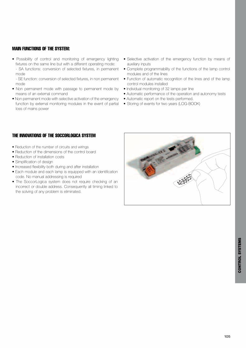
SOCCORLOGICA
• Possibility of control and monitoring of emergency lightingfixtures on the same line but with a different operating mode:- SA functions: conversion of selected fixtures, in permanentmode- SE function: conversion of selected fixtures, in non permanentmode
• Non permanent mode with passage to permanent mode bymeans of an external command
• Non permanent mode with selective activation of the emergencyfunction by external monitoring modules in the event of partialloss of mains power
• Selective activation of the emergency function by means ofauxiliary inputs
• Complete programmability of the functions of the lamp controlmodules and of the lines
• Function of automatic recognition of the lines and of the lampcontrol modules installed
• Individual monitoring of 32 lamps per line • Automatic performance of the operation and autonomy tests• Automatic report on the tests performed.• Storing of events for two years (LOG-BOOK)
MAIN FUNCTIONS OF THE SYSTEM:
THE INNOVATIONS OF THE SOCCORLOGICA SYSTEM
• Reduction of the number of circuits and wirings• Reduction of the dimensions of the control board• Reduction of installation costs• Simplification of design• Increased flexibility both during and after installation• Each module and each lamp is equipped with an identificationcode. No manual addressing is required
• The SoccorLogica system does not require checking of anincorrect or double address. Consequently all timing linked tothe solving of any problem is eliminated.
105
CO
NTR
OL
SYSTE
MS
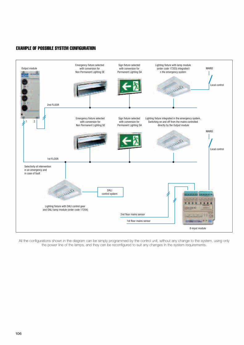
106
Output module
1 2
2nd FLOOR
1st FLOOR
1st floor mains sensor
2nd floor mains sensor
Emergency fixture selected with conversion for
Non Permanent Lighting SE
Sign fixture selected with conversion for
Permanent Lighting SA
Lighting fixture integrated in the emergency system. Switching on and off from the mains controlled
directly by the Output module
Selectivity of intervention in an emergency andin case of fault
MAINS
MAINS
Local control
Local control
8-input module
Emergency fixture selected with conversion for
Non Permanent Lighting SE
Sign fixture selected with conversion for
Permanent Lighting SA
Lighting fixture with lamp module (order code 17203) integrated i
n the emergency system
Lighting fixture with DALI control gear and DALI lamp module (order code 17204)
DALIcontrol system
EXAMPLE OF POSSIBLE SYSTEM CONFIGURATION
All the configurations shown in the diagram can be simply programmed by the control unit, without any change to the system, using onlythe power line of the lamps, and they can be reconfigured to suit any changes in the system requirements.
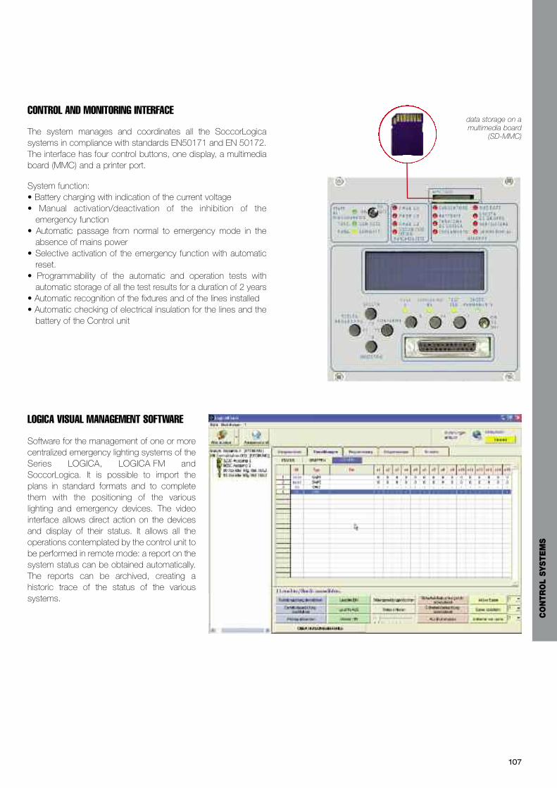
CONTROL AND MONITORING INTERFACE
The system manages and coordinates all the SoccorLogicasystems in compliance with standards EN50171 and EN 50172.The interface has four control buttons, one display, a multimediaboard (MMC) and a printer port.
System function:• Battery charging with indication of the current voltage• Manual activation/deactivation of the inhibition of theemergency function
• Automatic passage from normal to emergency mode in theabsence of mains power
• Selective activation of the emergency function with automaticreset.
• Programmability of the automatic and operation tests withautomatic storage of all the test results for a duration of 2 years
• Automatic recognition of the fixtures and of the lines installed• Automatic checking of electrical insulation for the lines and thebattery of the Control unit
LOGICA VISUAL MANAGEMENT SOFTWARE
Software for the management of one or morecentralized emergency lighting systems of theSeries LOGICA, LOGICA FM andSoccorLogica. It is possible to import theplans in standard formats and to completethem with the positioning of the variouslighting and emergency devices. The videointerface allows direct action on the devicesand display of their status. It allows all theoperations contemplated by the control unit tobe performed in remote mode: a report on thesystem status can be obtained automatically.The reports can be archived, creating ahistoric trace of the status of the varioussystems.
data storage on amultimedia board
(SD-MMC)
107
CO
NTR
OL
SYSTE
MS
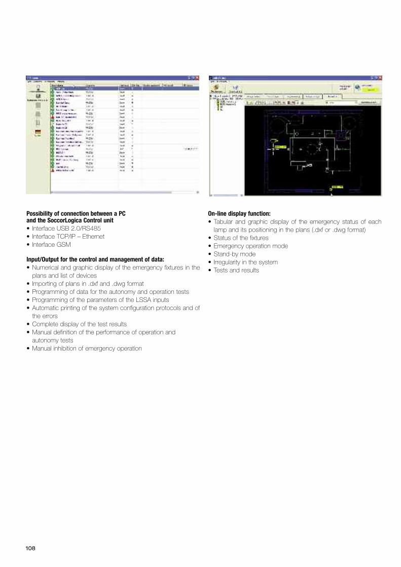
108
Possibility of connection between a PC and the SoccorLogica Control unit• Interface USB 2.0/RS485• Interface TCP/IP – Ethernet• Interface GSM
Input/Output for the control and management of data:• Numerical and graphic display of the emergency fixtures in theplans and list of devices
• Importing of plans in .dxf and .dwg format• Programming of data for the autonomy and operation tests• Programming of the parameters of the LSSA inputs• Automatic printing of the system configuration protocols and ofthe errors
• Complete display of the test results• Manual definition of the performance of operation andautonomy tests
• Manual inhibition of emergency operation
On-line display function:• Tabular and graphic display of the emergency status of eachlamp and its positioning in the plans (.dxf or .dwg format)
• Status of the fixtures• Emergency operation mode• Stand-by mode• Irregularity in the system• Tests and results
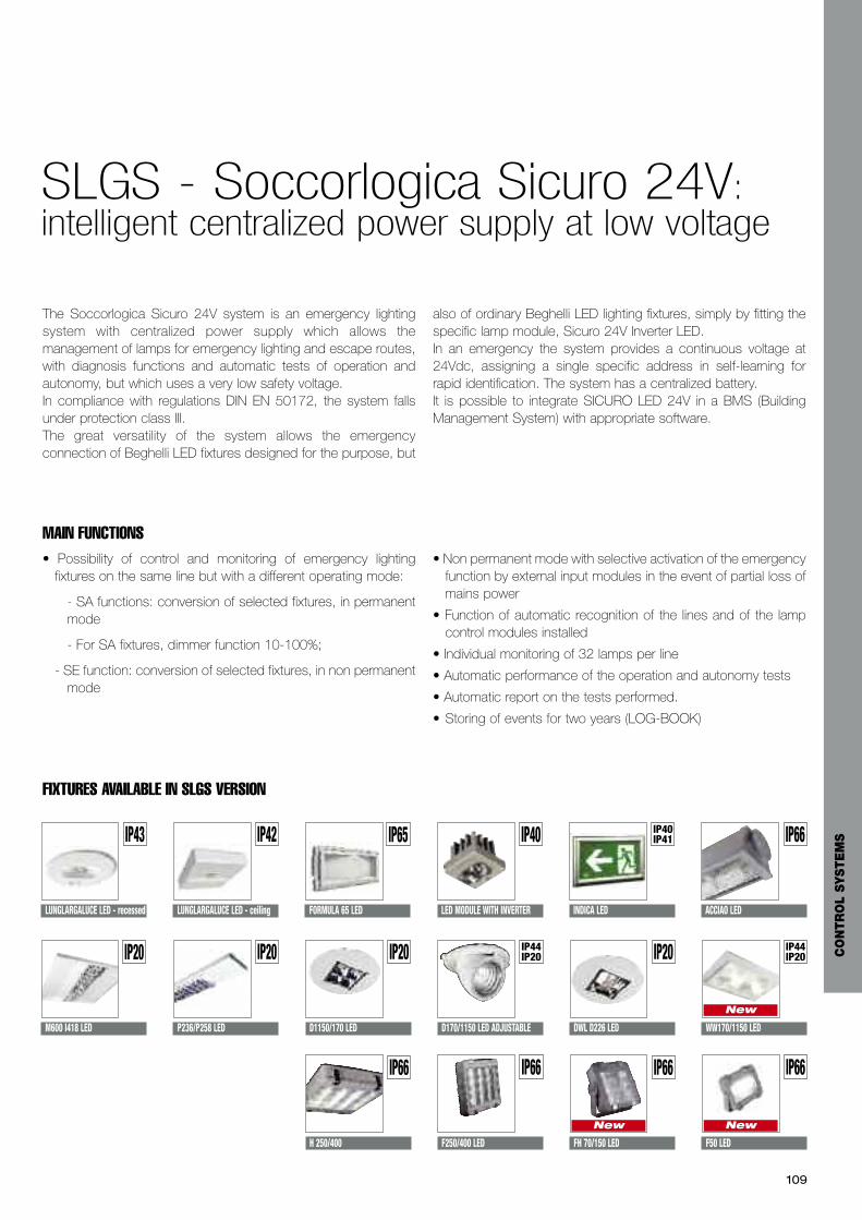
SLGS - Soccorlogica Sicuro 24V:intelligent centralized power supply at low voltage
109
The Soccorlogica Sicuro 24V system is an emergency lightingsystem with centralized power supply which allows themanagement of lamps for emergency lighting and escape routes,with diagnosis functions and automatic tests of operation andautonomy, but which uses a very low safety voltage.In compliance with regulations DIN EN 50172, the system fallsunder protection class III.The great versatility of the system allows the emergencyconnection of Beghelli LED fixtures designed for the purpose, but
also of ordinary Beghelli LED lighting fixtures, simply by fitting thespecific lamp module, Sicuro 24V Inverter LED.In an emergency the system provides a continuous voltage at24Vdc, assigning a single specific address in self-learning forrapid identification. The system has a centralized battery.It is possible to integrate SICURO LED 24V in a BMS (BuildingManagement System) with appropriate software.
FIXTURES AVAILABLE IN SLGS VERSION
• Possibility of control and monitoring of emergency lightingfixtures on the same line but with a different operating mode:
- SA functions: conversion of selected fixtures, in permanentmode
- For SA fixtures, dimmer function 10-100%;
- SE function: conversion of selected fixtures, in non permanentmode
• Non permanent mode with selective activation of the emergencyfunction by external input modules in the event of partial loss ofmains power
• Function of automatic recognition of the lines and of the lampcontrol modules installed
• Individual monitoring of 32 lamps per line
• Automatic performance of the operation and autonomy tests
• Automatic report on the tests performed.
• Storing of events for two years (LOG-BOOK)
MAIN FUNCTIONS
LUNGLARGALUCE LED - recessed LUNGLARGALUCE LED - ceiling
IP43 IP42
FORMULA 65 LED
IP65
LED MODULE WITH INVERTER
IP40
INDICA LED
IP40IP41
P236/P258 LED
IP20
H 250/400
IP66
M600 I418 LED
IP20
DWL D226 LED
IP20
IP66
ACCIAO LED
CO
NTR
OL
SYSTE
MS
D1150/170 LED
IP20
WW170/1150 LED
IP44IP20
New
D170/1150 LED ADJUSTABLE
IP44IP20
F250/400 LED
IP66
FH 70/150 LED
IP66
New
F50 LED
IP66
New

110
SLG Sicuro Control unit
THE ELEMENTS• Device for automatic control and monitoring, in compliance withstandard EN 62034. Monitoring is carried out by means of twotypes of tests. The shorter one evaluates the perfect operationof the system (functional test) and the more detailed oneevaluates the emergency autonomy (duration test). The testresults are stored in the SicuroLED device.
• Charger 27.2 V / 3A 27.2V / 5A, 27.2V 10A
• Automatic emergency activation in the absence of mainspower. The system also allows the emergency to be managedautonomously on the various system sections.
• The mains presence on the distributions is indicated to thesystem by single-phase or three-phase mains sensor devices.They are fitted downstream from the differentials/disconnectingswitches and monitor the single phase or the three phases.
• Each SicuroLED Control unit manages up to 128 lamps,subdivided into 4 lines of maximum 32 lamps each. Maincharacteristics and functions of the system:
- integration of SE and SA functionality
- Univocal and automatic addressing of the lamps
- Targeted monitoring of the single lamp
- In the presence of mains power, the lamps can be dimmedfrom 10% to 100%
- SA lamps can be switched on or off directly by the controlunit, or by remote control by means of the input module 3+5
- In case of maintenance on the mains it is possible to time theswitching on and off of the lamps
• 3 relay outputs (programmable) for indicating:
- battery charging error
- battery error
- lamp error
- reaching minimum battery threshold
• RS485 interface for:
- interfacing max 2 input modules
- interfacing monitoring with optional Sicuro-Visual software
• ETHERNET interface for communication via
• USB interface for uploading and downloading the systemconfiguration, the results of the tests performed, and forupdating the software of the system and of the SicuroLEDmodules.
• Lead batteries, life expectancy 10 years at working temperature20°C.
GENERAL CHARACTERISTICS
Protection Class I
Protection grade IP20
Autonomy 1h - 3h, 1-2.20h
Working temperature -5°C ÷ +25°C
Autonomy 1h - 3h, 1-2.20h
Battery 24V DC
Power supply 1~N/PE, 230VAC +-10%, 50/60Hz
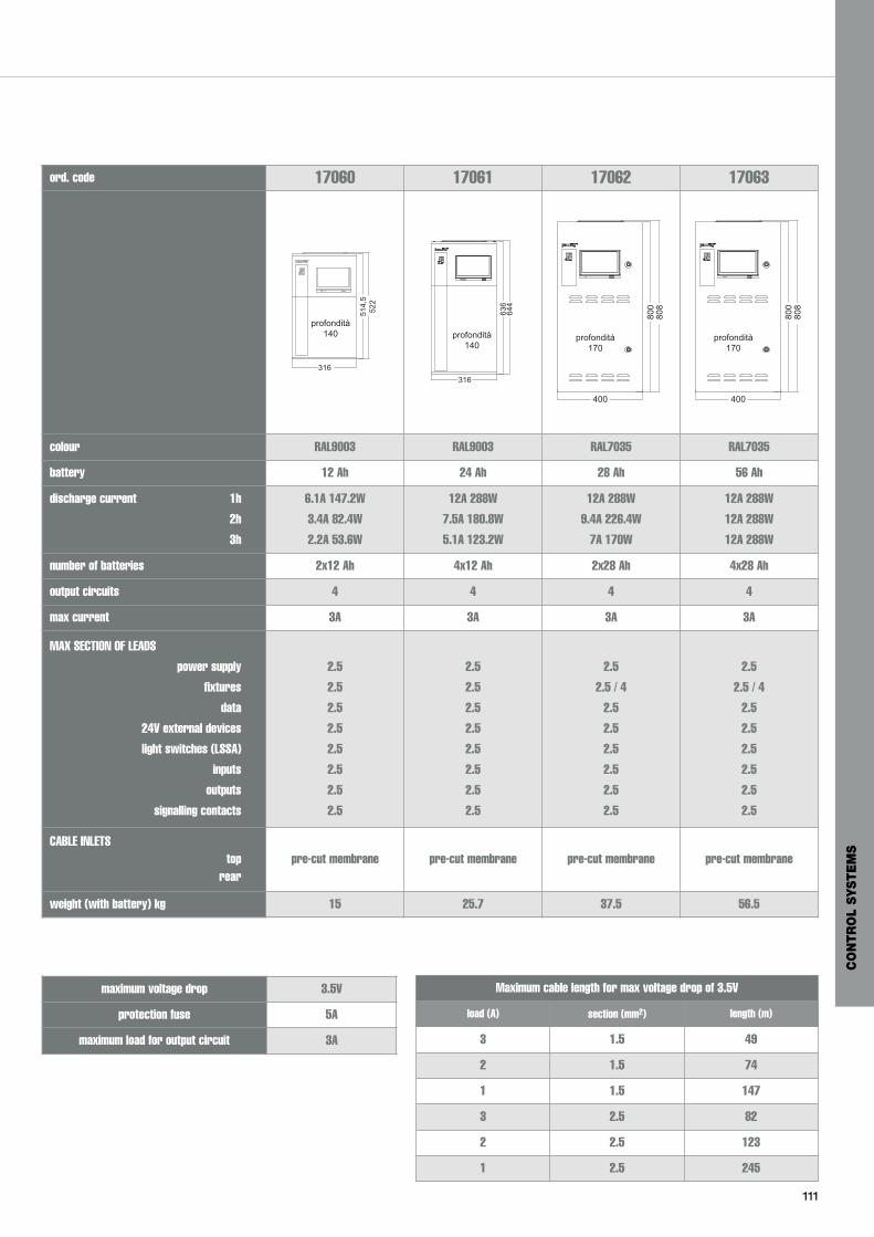
111
SLG Sicuro Control unit
ord. code 17060 17061 17062 17063
profondità140
316514,5
522
316
636
644
profondità140
400
800
808
profondità170
400
800
808
profondità170
colour RAL9003 RAL9003 RAL7035 RAL7035
battery 12 Ah 24 Ah 28 Ah 56 Ah
discharge current 1h
2h
3h
6.1A 147.2W
3.4A 82.4W
2.2A 53.6W
12A 288W
7.5A 180.8W
5.1A 123.2W
12A 288W
9.4A 226.4W
7A 170W
12A 288W
12A 288W
12A 288W
number of batteries 2x12 Ah 4x12 Ah 2x28 Ah 4x28 Ah
output circuits 4 4 4 4
max current 3A 3A 3A 3A
MAX SECTION OF LEADS
power supply
fixtures
data
24V external devices
light switches (LSSA)
inputs
outputs
signalling contacts
2.5
2.5
2.5
2.5
2.5
2.5
2.5
2.5
2.5
2.5
2.5
2.5
2.5
2.5
2.5
2.5
2.5
2.5 / 4
2.5
2.5
2.5
2.5
2.5
2.5
2.5
2.5 / 4
2.5
2.5
2.5
2.5
2.5
2.5
CABLE INLETStop
rearpre-cut membrane pre-cut membrane pre-cut membrane pre-cut membrane
weight (with battery) kg 15 25.7 37.5 56.5
maximum voltage drop 3.5V
protection fuse 5A
maximum load for output circuit 3A
Maximum cable length for max voltage drop of 3.5V
load (A) section (mm2) length (m)
3 1.5 49
2 1.5 74
1 1.5 147
3 2.5 82
2 2.5 123
1 2.5 245
CO
NTR
OL
SYSTE
MS
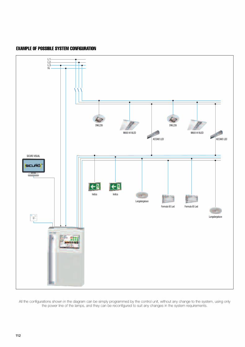
112
L1L2L3N
Indica Indica
Lungalargaluce
M600 I418LED M600 I418LED
Formula 65 Led Formula 65 Led
Lungalargaluce
DWL226 DWL226
ACCIAIO LED ACCIAIO LED
SICURO VISUAL
EXAMPLE OF POSSIBLE SYSTEM CONFIGURATION
All the configurations shown in the diagram can be simply programmed by the control unit, without any change to the system, using onlythe power line of the lamps, and they can be reconfigured to suit any changes in the system requirements.
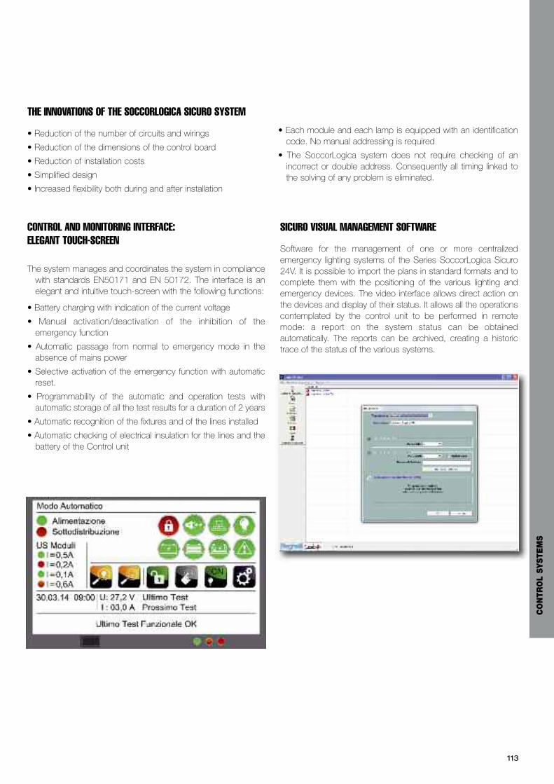
113
SICURO VISUAL MANAGEMENT SOFTWARE
Software for the management of one or more centralizedemergency lighting systems of the Series SoccorLogica Sicuro24V. It is possible to import the plans in standard formats and tocomplete them with the positioning of the various lighting andemergency devices. The video interface allows direct action onthe devices and display of their status. It allows all the operationscontemplated by the control unit to be performed in remotemode: a report on the system status can be obtainedautomatically. The reports can be archived, creating a historictrace of the status of the various systems.
THE INNOVATIONS OF THE SOCCORLOGICA SICURO SYSTEM
• Reduction of the number of circuits and wirings
• Reduction of the dimensions of the control board
• Reduction of installation costs
• Simplified design
• Increased flexibility both during and after installation
• Each module and each lamp is equipped with an identificationcode. No manual addressing is required
• The SoccorLogica system does not require checking of anincorrect or double address. Consequently all timing linked tothe solving of any problem is eliminated.
CONTROL AND MONITORING INTERFACE: ELEGANT TOUCH-SCREEN
The system manages and coordinates the system in compliancewith standards EN50171 and EN 50172. The interface is anelegant and intuitive touch-screen with the following functions:
• Battery charging with indication of the current voltage
• Manual activation/deactivation of the inhibition of theemergency function
• Automatic passage from normal to emergency mode in theabsence of mains power
• Selective activation of the emergency function with automaticreset.
• Programmability of the automatic and operation tests withautomatic storage of all the test results for a duration of 2 years
• Automatic recognition of the fixtures and of the lines installed
• Automatic checking of electrical insulation for the lines and thebattery of the Control unit
CO
NTR
OL
SYSTE
MS
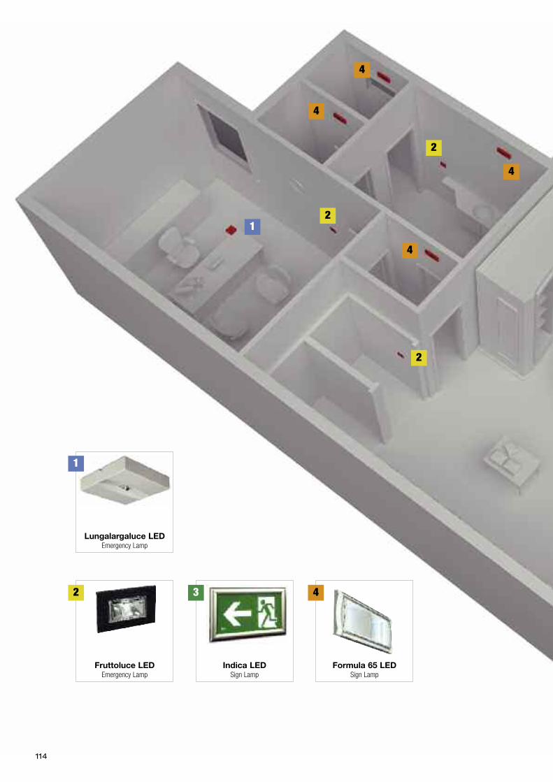
114
2
2
2
1
1
Lungalargaluce LEDEmergency Lamp
2
Fruttoluce LEDEmergency Lamp
4
Formula 65 LEDSign Lamp
4
4
4
4
3
Indica LEDSign Lamp
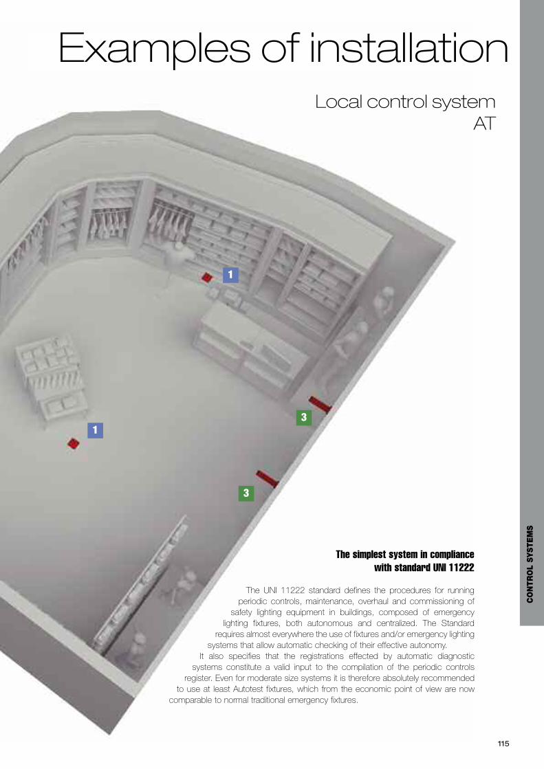
115
Local control systemAT
The simplest system in compliance with standard UNI 11222
The UNI 11222 standard defines the procedures for runningperiodic controls, maintenance, overhaul and commissioning of
safety lighting equipment in buildings, composed of emergencylighting fixtures, both autonomous and centralized. The Standard
requires almost everywhere the use of fixtures and/or emergency lightingsystems that allow automatic checking of their effective autonomy.
It also specifies that the registrations effected by automatic diagnosticsystems constitute a valid input to the compilation of the periodic controls
register. Even for moderate size systems it is therefore absolutely recommendedto use at least Autotest fixtures, which from the economic point of view are now
comparable to normal traditional emergency fixtures.
3
3
1
1
Examples of installation
CO
NTR
OL
SYSTE
MS
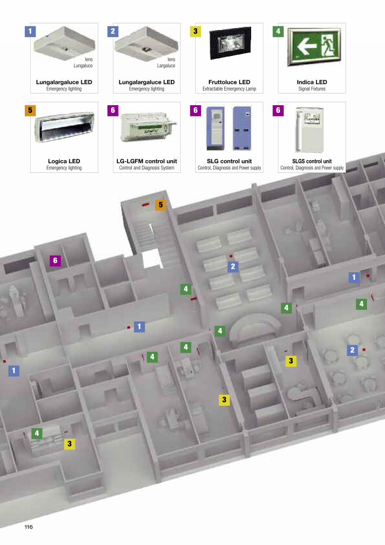
116
2
2
2
3
3
3
5
44
1
1
14
44
4
4
Lungalargaluce LEDEmergency lighting
1
Lungalargaluce LEDEmergency lighting
lensLungaluce
lensLargaluce
3
Fruttoluce LEDExtractable Emergency Lamp
5
Logica LEDEmergency lighting
6
6
LG-LGFM control unitControl and Diagnosis System
6
SLG control unitControl, Diagnosis and Power supply
4
Indica LEDSignal Fixtures
6
SLGS control unitControl, Diagnosis and Power supply
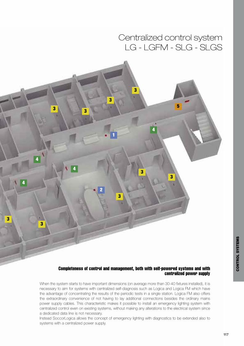
2
33
3
33
3
3
33 5
4
4
4
4
1
117
Centralized control systemLG - LGFM - SLG - SLGS
Completeness of control and management, both with self-powered systems and withcentralized power supply
When the system starts to have important dimensions (on average more than 30-40 fixtures installed), it isnecessary to aim for systems with centralized self-diagnosis such as Logica and Logica FM which havethe advantage of concentrating the results of the periodic tests in a single station. Logica FM also offersthe extraordinary convenience of not having to lay additional connections besides the ordinary mainspower supply cables. This characteristic makes it possible to install an emergency lighting system withcentralized control even on existing systems, without making any alterations to the electrical system sincea dedicated data line is not necessary.Instead SoccorLogica allows the concept of emergency lighting with diagnostics to be extended also tosystems with a centralized power supply.
CO
NTR
OL
SYSTE
MS

118
The Academyfor professionals
Workshops, documentation and services to support design
Beghelli Accademia is a space for knowledge and exchange, atthe disposal of professionals in lighting design.A space where they can:- investigate every aspect of LIGHT, the principal theories, thelegislation, the technical solutions
- train in workshops organized throughout the national territory- find a tangible support service for their design activityA special section of Beghelli Academy is active on-line, accessiblefrom the home page of beghelli.it, where a collection of
publications, technical documentations and useful support fordesign studios can be found, the contents of which are updatedregularly. The dates, programmes and final reports of theworkshops are published in this area.An electronic catalogue can also be consulted, containing fullinformation on the Beghelli offer. The technical data sheet of everysingle fixture is published, with the image, product code,photometric curve, assembly instructions, text for specifications,energy classification, taken from the respective catalogue. Lastly atangible support service for their design activity is available.For information and sending projects: [email protected]
A C C A D E M I A
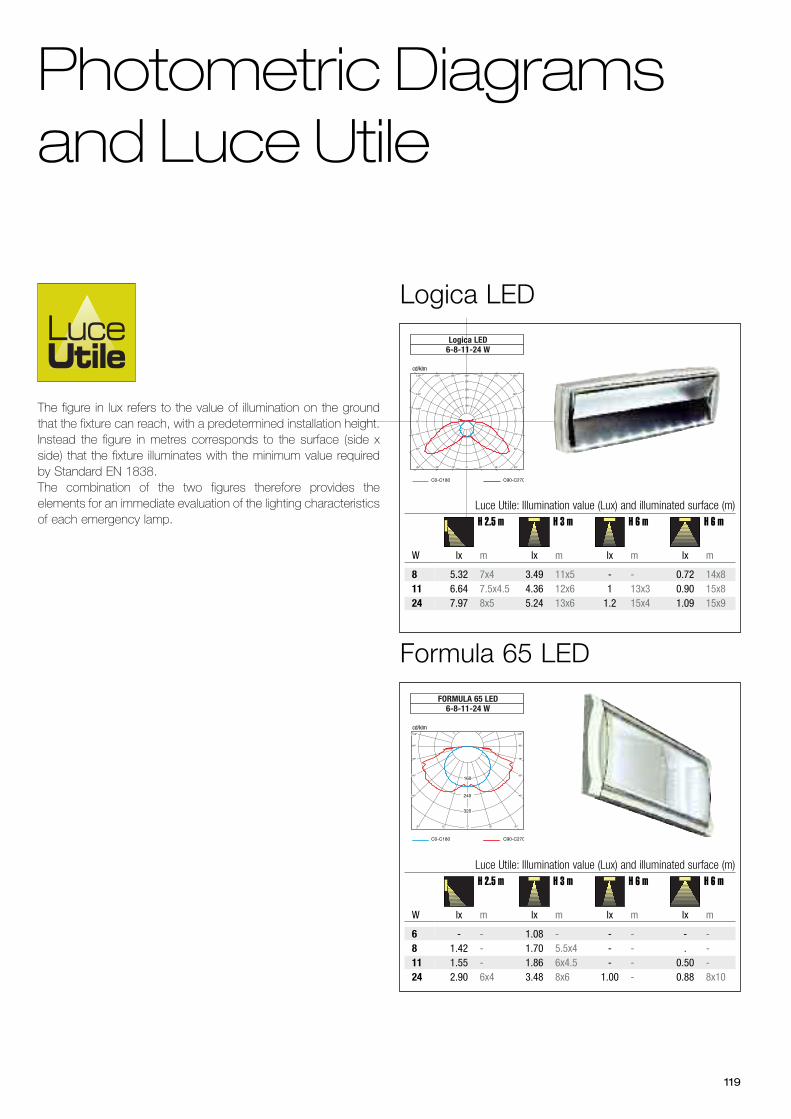
119
C0-C180 C90-C270
cd/klm
FORMULA 65 LED6-8-11-24 W
240
320
160
105°
90°
75°
60°
45°
105°
90°
75°
60°
45°
30° 15° 0° 15° 30°
- - 1.08 - - - - -1.42 - 1.70 5.5x4 - - . -1.55 - 1.86 6x4.5 - - 0.50 -2.90 6x4 3.48 8x6 1.00 - 0.88 8x10
lx m lx m lx m lx m
681124
Luce Utile: Illumination value (Lux) and illuminated surface (m)
W
H 2.5 m H 3 m H 6 m H 6 m
Formula 65 LED
C0-C180 C90-C270
cd/klm
Logica LED6-8-11-24 W
100
150
200
250
0° 15° 30° 45°
60°
75°
90°
105°
120°
135°150°165°180°165°150°135°
120°
105°
90°
75°
60°
45° 30° 15° 0°
Photometric Diagramsand Luce Utile
5.32 7x4 3.49 11x5 - - 0.72 14x86.64 7.5x4.5 4.36 12x6 1 13x3 0.90 15x87.97 8x5 5.24 13x6 1.2 15x4 1.09 15x9
lx m lx m lx m lx m
81124
Luce Utile: Illumination value (Lux) and illuminated surface (m)
W
H 2.5 m H 3 m H 6 m H 6 m
The figure in lux refers to the value of illumination on the groundthat the fixture can reach, with a predetermined installation height.Instead the figure in metres corresponds to the surface (side xside) that the fixture illuminates with the minimum value requiredby Standard EN 1838.The combination of the two figures therefore provides theelements for an immediate evaluation of the lighting characteristicsof each emergency lamp.
Logica LED
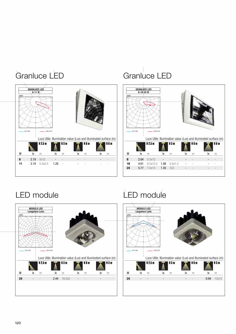
120
C0-C180 C90-C270
MODULO LEDLungaluce Lens
cd/klm
1000
1500
2000
2500
3000
0° 15° 30° 45°
60°
75°
90°
105°
120°
135°150°165°180°165°150°135°
120°
105°
90°
75°
60°
45° 30° 15° 0°
C0-C180 C90-C270
MODULO LEDLargaluce Lens
cd/klm
320
480
640
0° 15° 30°
45°
60°
75°
90°
105°105°
90°
75°
60°
45°
30° 15° 0°
- - 2.44 16.5x2 - - - -
lx m lx m lx m lx m
24
Luce Utile: Illumination value (Lux) and illuminated surface (m)
W
H 2.5 m H 3 m H 6 m H 3 m
- - - - - - 0.94 12x12
lx m lx m lx m lx m
24
Luce Utile: Illumination value (Lux) and illuminated surface (m)
W
H 2.5 m H 3 m H 6 m H 3 m
LED moduleLED module
C0-C180 C90-C270
GRANLUCE LED6-11 W
cd/klm
1600
2400
3200
0° 15° 30°
45°
60°
75°
90°
105°105°
90°
75°
60°
45°
30° 15° 0°
2.19 5x12 - - - - - -3.19 5.5x2.5 1.20 - - - . -
lx m lx m lx m lx m
611
Luce Utile: Illumination value (Lux) and illuminated surface (m)
W
H 2.5 m H 3 m H 6 m H 6 m
Granluce LED
C0-C180 C90-C270
GRANLUCE LED8-18-24 W
cd/klm
0° 15° 30°
45°
60°
75°
90°
105°105°
90°
75°
60°
45°
30° 15° 0°
3000
1500
1000
2000
2500
2.64 5.5x12 - - - - - -4.61 6.5x12.5 1.08 5.5x1.5 - - - -5.77 7.5x13 1.35 7x2 - - - -
lx m lx m lx m lx m
81824
Luce Utile: Illumination value (Lux) and illuminated surface (m)
W
H 2.5 m H 3 m H 6 m H 6 m
Granluce LED
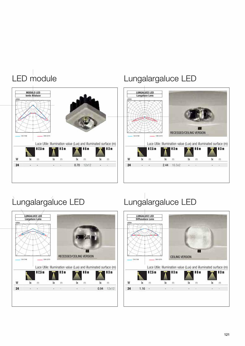
121
C0-C180 C90-C270
MODULO LEDlente Altaluce
cd/klm
300
400
500
600
0° 15° 30°
45°
60°
75°
90°
105°105°
90°
75°
60°
45°
30° 15° 0°
C0-C180 C90-C270
LUNGALUCE LEDLungaluce Lens
cd/klm
1000
1500
2000
2500
3000
0° 15° 30° 45°
60°
75°
90°
105°
120°
135°150°165°180°165°150°135°
120°
105°
90°
75°
60°
45° 30° 15° 0°
C0-C180 C90-C270
LUNGALUCE LEDLargaluce Lens
cd/klm
320
480
640
0° 15° 30°
45°
60°
75°
90°
105°105°
90°
75°
60°
45°
30° 15° 0°
C0-C180 C90-C270
cd/klm
LUNGALUCE LEDDiffusaluce Lens
150
100
200
250
300
0° 15° 30°
45°
60°
75°
90°
105°105°
90°
75°
60°
45°
30° 15° 0°
- - 2.44 16.5x2 - - - -
lx m lx m lx m lx m
24
Luce Utile: Illumination value (Lux) and illuminated surface (m)
W
RECESSED/CEILING VERSION
H 2.5 m H 3 m H 6 m H 3 m
- - - - 0.70 12x12 - -
lx m lx m lx m lx m
24
Luce Utile: Illumination value (Lux) and illuminated surface (m)
W
H 2.5 m H 3 m H 6 m H 3 m
- - - - - - 0.94 12x12
lx m lx m lx m lx m
24
Luce Utile: Illumination value (Lux) and illuminated surface (m)
W
H 2.5 m H 3 m H 6 m H 3 m
CEILING VERSION
RECESSED/CEILING VERSION
1.16 - - - - - - -
lx m lx m lx m lx m
24
Luce Utile: Illumination value (Lux) and illuminated surface (m)
W
H 2.5 m H 3 m H 6 m H 3 m
Lungalargaluce LED
Lungalargaluce LEDLungalargaluce LED
LED module
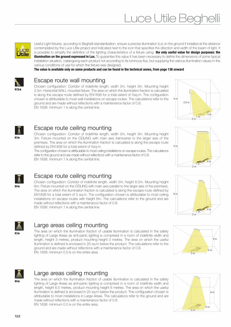
Luce Utile Beghelli
122
H 6 m
5 m
6 m
5 m
Large areas ceiling mountingThe area on which the illumination fraction of usable illumination is calculated in the safetylighting of Large Areas as anti-panic lighting is comprised in a room of indefinite width andlength, height 6.5 metres, product mounting height 6 metres. The area on which the usefulillumination is defined is enclosed in 25 sq.m below the product. The configuration chosen isattributable to most installations in Large Areas. The calculations refer to the ground and aremade without reflections with a maintenance factor of 0.8.EN 1838: minimum 0.5 lx on the entire area.
H 3 m
5 m
3 m
5 m
Large areas ceiling mountingThe area on which the illumination fraction of usable illumination is calculated in the safetylighting of Large Areas as anti-panic lighting is comprised in a room of indefinite width andlength, height 3 metres, product mounting height 3 metres. The area on which the usefulillumination is defined is enclosed in 25 sq.m below the product. The calculations refer to theground and are made without reflections with a maintenance factor of 0.8.EN 1838: minimum 0.5 lx on the entire area.
Useful Light fixtures, according to Beghelli standardization, ensure a precise illumination (Lx) on the ground if installed at the distancecontemplated by the Luce Utile project and indicated next to the icon that specifies the direction and width of the beam of light. Itis possible to simplify the definition of the lighting characteristics of a fixture using the only useful value for design purposes: theillumination on the ground expressed in Lux. To guarantee this value it has been necessary to define the dimensions of some typicalinstallation situation, cataloguing each product not according to its luminous flux, but supplying the various illumination values in thevarious conditions of use for which the fixture was designed. The value is available only on some products and can be found in the technical annex, from page 136 onward
H 6 m
H 3 m
H 2.5 m
3 m
2 m1 m
5 m
2,5 m
Escape route wall mountingChosen configuration: Corridor of indefinite length, width 2m, height 3m. Mounting height2.5m. Horizontal WALL mounted fixture. The area on which the illumination fraction is calculatedis along the escape route defined by EN1838 for a total extent of 5sq.m. The configurationchosen is attributable to most wall installations on escape routes. The calculations refer to theground and are made without reflections with a maintenance factor of 0.8.EN 1838: minimum 1 lx along the central line.
3 m
2 m1 m
5 m
Escape route ceiling mountingChosen configuration: Corridor of indefinite length, width 2m, height 3m. Mounting height3m. Fixture mounted on the CEILING with main axis transverse to the larger axis of thepremises. The area on which the illumination fraction is calculated is along the escape routedefined by EN1838 for a total extent of 5sq.m. The configuration chosen is attributable to most ceiling installations on escape routes. The calculationsrefer to the ground and are made without reflections with a maintenance factor of 0.8.EN 1838: minimum 1 lx along the central line.
6 m
2 m1 m
5 m
Escape route ceiling mountingChosen configuration: Corridor of indefinite length, width 2m, height 6.5m. Mounting height6m. Fixture mounted on the CEILING with main axis parallel to the larger axis of the premises.The area on which the illumination fraction is calculated is along the escape route defined byEN1838 for a total extent of 5 sq.m. The configuration chosen is attributable to most ceilinginstallations on escape routes with height 6m. The calculations refer to the ground and aremade without reflections with a maintenance factor of 0.8.EN 1838: minimum 1 lx along the central line.
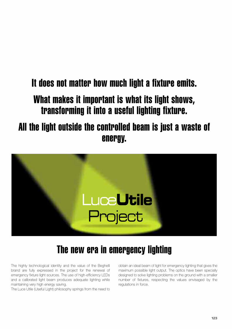
The highly technological identity and the value of the Beghellibrand are fully expressed in the project for the renewal ofemergency fixture light sources. The use of high-efficiency LEDsand a calibrated light beam produces adequate lighting whilemaintaining very high energy saving.The Luce Utile (Useful Light) philosophy springs from the need to
obtain an ideal beam of light for emergency lighting that gives themaximum possible light output. The optics have been speciallydesigned to solve lighting problems on the ground with a smallernumber of fixtures, respecting the values envisaged by theregulations in force.
LuceUtileProject
It does not matter how much light a fixture emits.What makes it important is what its light shows,
transforming it into a useful lighting fixture.All the light outside the controlled beam is just a waste of
energy.
The new era in emergency lighting
123
Environmental protection
RHOS DIRECTIVE 2002/95/EC
In order to facilitate the recovery and recycling of electrical equipment and to avoid the accumulation ofhazardous substances in the environment, the European community issured the RHOS directive,acknowledged in Italy with the same decree as the WEEE directive, that is DM 151 of 25 July 2005. TheDirective was rewritten and issued with reference 2011/65 with new obligations for producers in termsof documentation. The substantial provisions remain unchanged:
Without prejudice to annex 5, as from 1st July 2006 it is forbidden to launch on the market new electricaland electronic equipment falling under the categories identified in annex 1A, as well as incandescent lightsources containing lead, mercury, cadmium, hexavalent chromium, polybrominated biphenyls (PBBs) orpolybrominated diphenyl ether (PBDE).
Exceptions and exemptions to this regulation are contemplated, in particular the veto on mercury is notapplied to compact fluorescent lamps and fluorescent tubes containing mercury in quantities notexceeding the allowed limits. Other exceptions are contemplated and are continuously updated. Fordetails see the site www.ec.europa.eu/environment/waste/rohs_consult.htm
All Beghelli products and lamps first of all are made in compliance with the ROHS Directive, as rewrittenin 2011
WEEE DIRECTIVE 2002/96/ECThe quantity of waste derived from electrical and electronic equipment (WEEE) is increasingly rapidly anda large part consists of light sources (excluding incandescent filament lamps).The main objective of the directive is to prevent WEEE thrown, at the end of their working life, into landfillor incinerators, causing a further serious impact on the environment. Directive 2002/96/EC has therefore sought to introduce a control mechanism which envisages acontrolled management of the device at the end of its working life, to encourage its reuse or recycling.The legislative mechanism also promotes design and production concepts that make product disposaleasier, in terms of both disassembly and materials.In the case of lamps, the financing of activities connected to the collection, management and recyclingof WEEE at the end of their working life is guaranteed by a visible fee applied at the moment of sale.
All passages in the commercial chain are required to make a contribution, some in economic terms, somein terms of activity, to ensure that the spirit of the directive is respected (and the environment isprotected).
In Italy the directive was acknowledged with decree 151 of 25 July 2005 and subsequently integrated inother implementing decrees.
THESE ARE THE PRINCIPAL OBLIGATIONS ENVISAGEDThe producer (understood in the broad sense and therefore substantially whoever applies his brand onthe goods and who imports from another country) is responsible for the costs of disposal of his productsat the end of their working life.The sales outlet is required to collect the product at the end of its working life if it replaced by a new oneof the same kind.The consumer is required to manage the item sensibly at the end of its life, consigning it to an equippedcollection point, a sales area, or following the manufacturer’s indications.
Beghelli has always been aware of the environmental problem and is one of the founder members of theECOLIGHT consortium, to which the company consigns all the collected visible contribution.
Choosing products and companies that rely on voluntary consortiums for the recovery and recycling ofproducts is a responsible and ecologically correct choice for the protection of the environment and for ourfuture.
The products that fall within the field of application of the WEEE directive are identified by the symbolalongside (there is also the version not crossed-out).
132
Concessionario Marchio IMQ
Associato:
General terms of sale
Beghelli products are manufactured to state-of-the-art standards in terms of safety, in compliance with therequirements of laws 186/68 and 791/77, and do not compromise the safety of persons, pets or property,if installed and used according to their intended purpose and correctly fitted. Moreover, the products thatfall within the field of application of the EEC Directives (“EMC” Directive 89/336/EEC - acknowledged withLaw Decree 476/92 - amended by Directive 93/68/EEC and the “BT” Directive 73/23/EEC - acknowledgedwith Law 791/77 - amended by Directive 93/68/EEC) comply with the essential requirements containedtherein. The CE mark applied on the product and/or on the packaging and/or on any warnings for use thataccompany the product “indicates presumed conformity with the Directives” mentioned above. Beghellikeeps a Technical Archive, at the disposal of the competent authorities for any inspections, containing thedocumentation demonstrating that the produce has been examined to assess its conformity.
The data contained in this catalogue may be subject to variation without notice. All the products includedare covered by the Beghelli guarantee according to the laws in force, unless indicated otherwise in theguarantee supplied with every single product.
The products for Building Automation, Air Conditioning and Anti-intrusion are included in the “IntelligentBeghelli” catalogue. Energy saving lamps, Air Treatment, Remote Assistance, Safety, Portable Lighting,Health and Safety for Infancy, are included in the “Beghelli Commercial Line” catalogue.
All the above-mentioned catalogues are available on the site www.beghelli.com or may berequested from: Beghelli S.p.A. - Sales Management - Via Mozzeghine, 13/15 - 40053Valsamoggia loc. Monteveglio - Bologna
© Cop
yright 04/20
15
1. ORDERS - FINALIZATION OF AGREEMENTSProduct purchase orders must be made in writing. Placing of an order is considered irrevocable. TheSeller reserves the faculty to fulfil orders also in part, or to cancel them, even any residual part, in theevent of a change of the situation of the Buyer. All collaboration programmes, orders, commissions andagreements are intended as finalized with the written or verbal confirmation by the Seller, or at any ratewith the start of invoicing and/or delivery of the products ordered.
2. VARIATIONS AND MODIFICATIONSAfter finalization of the order, any modification or integration of the content and terms of the order shallbe valid and become effective only when the Seller sends the Buyer a variation of the confirmation. Thetext of the confirmation or of the variation of the confirmation by the Seller shall prevail in any case overany other document.Should the Buyer not wish to accept the terms that differ from his order, he must point it out within 20(twenty) days of the date of confirmation, otherwise the variation of confirmation shall be deemedaccepted in full.
3. ACCEPTANCE PROCEDUREThe Seller cannot be held liable for non acceptance of an order, or for non delivery or delayed delivery ofthe products ordered. The acceptance and execution of the order are specifically subordinate to theavailability of the products ordered and to the absence of circumstances that could in any way influencetheir availability and the promptness of their delivery.
4. DELIVERY TERMSThe delivery terms communicated by the Seller are purely indicative.The delivery terms expressed in days are normally calculated in working days.Any modifications to the delivery terms requested by the Buyer must be accepted in writing by the Seller.Any delays in delivery, and any interruptions and/or total or partial suspensions of delivery, even if notdue to force majeure and/or act of providence, shall not entitle the Buyer to claim a refund for damagesand/or compensation of any kind nor even interest; the Buyer shall have the sole faculty to cancel theorder upon written notice to the Seller of at least thirty days counted from the date of receipt of theregistered letter with recorded delivery sent by the Buyer.
5. FORCE MAJEUREWithout limitation, the following are to be considered causes of force majeure: strikes, lockouts, rebellion,labour conflicts, fire, natural calamities, impossibility to provision products, interruptions or difficulties intransport, delayed deliveries, lack of raw materials, actions of the government and authorities, failure ofsuppliers and, in general, any unforeseeable event which cannot be reasonably considered to be underthe control of the Seller. In all such cases, as in the event of act of providence, the Seller reserves thefaculty to suspend and/or delay the delivery of the products and even to cancel the orders, even if alreadyconfirmed, without this entitling the Buyer to claim a refund from the Seller for damages and/orcompensation of any kind, including direct, indirect and consequential damage.
6. DELIVERY - TRANSPORTThe goods always travel at the Buyer’s own risk, even when sent carriage paid and/or with the Seller’svehicle, so the Seller shall not accept any complaints for any breakages and/or tampering with theproducts. Delivery of the products is considered made from the headquarters of the Seller at Monteveglio(Bologna). Transport expenses are borne by the Buyer. The Seller does not accept returned packaging.
7. COMPLAINTS - REPLACEMENT OF PRODUCTSFor replacements and complaints the safeguards contemplated by the law are applied, applicable to thespecific type of customer, professional operator or consumer. As soon as the products are received, theBuyer is required to check the condition, the quantity of the supply and to ensure that it corresponds tothe delivery note. Any complaints concerning quality, quantity or type of product must be made in writingwithin 8 (eight) days of the date of receipt of the goods. Once that time has expired, and without prejudiceto the various guarantee conditions envisaged for the individual products, no complaint can be maderegarding the substance and quality of the goods, or for their general conditions. The Buyer may for noreason return the products without prior authorization of the Seller in writing, nor delay and/or totally orpartially suspend payment of the invoices, not even in the case of complaints. Should there be groundsfor the complaint, in the Seller’s opinion, and if it has been made within the guarantee terms indicated inthe illustrative booklets that accompany the individual products, the guarantee obligation is limited to thesimple replacement of the non conforming product according to the delivery procedures of the firstsupply. Any right of the Buyer to cancel the order or to obtain any refund for expenses and/or damagesis therefore excluded. The right to replacement of the disputed product expires if the product is not keptdiligently, at the Seller’s disposal, and immediately returned to the place established by the Seller.
8. PRICESThe prices indicated in the Seller’s price lists are not binding, consequently the Seller reserves the rightto modify them until the time of delivery of the products.The prices are net of VAT and of any other fiscal dues.
9. PAYMENTSAll payments must be made at the times and with the methods indicated by the Seller to the latter’sheadquarters at Monteveglio (Bologna) or to the person indicated and duly authorized in writing by theSeller. In the case of a delay in payment, the defaulting buyer shall be required to pay the Seller interestfor arrears from the due date of the contractual term until the date of settlement, according to the prime-rate in force at the time (as determined by the Italian Banking Association - ABI) plus 5 (five) points,without prejudice to claims for further loss. Failure by the Buyer to respect the terms of payment shallentitle the Seller to terminate the respective supply contract with immediate effect and to suspenddelivery of all products that may be ordered without the need for any communication, with the consequentright for the Seller to demand the immediate payment of the entire credit and to take action for thecompensation of damage suffered.
10. LIEN AGREEMENTThe products are sold under a lien agreement; they shall therefore remain the property of the Seller untilfull payment has been made. The Buyer therefore undertakes to inform third parties of the existence and efficacy of this lienagreement, and to safeguard the Seller’s rights deriving therefrom.
11. COMPETENT COURTFor any controversy or dispute concerning the interpretation, validity and execution of the order, orconnected in any way to the contracts to which these general terms of sale apply, the exclusive competentcourt shall be the Court of Bologna.
133


![Ihr Spezialist für Mess- und Prüfgeräte · PDF fileRaumwinkel Ω [Steradiant, sr] ... DIN EN 12464-1 Arbeitsstätten in Innenräumen..... 37 DIN EN 12464-2 Arbeitsplätze im Freien](https://img.pdfslide.net/doc/110x75/5a79a1597f8b9ab45c8d57ad/ihr-spezialist-fr-mess-und-steradiant-sr-din-en-12464-1-arbeitssttten.jpg)


![Normativa de Iluminacion en 12464-1[2]](https://img.pdfslide.net/doc/110x75/55cf9962550346d0339d16e1/normativa-de-iluminacion-en-12464-12.jpg)