Embed Size (px)
Citation preview
25 March 2014
Electranix Corporation, 12 – 75 Scurfield Blvd, Winnipeg, MB R3Y 1G4, Canada. www.electranix.com
Symmetrical Monopole VSC Transmission
By Dennis Woodford
Background The VSC configuration of the future will be Modular Multi-level Converter (MMC). Converter technology is a fast moving technology and this is a summary of the present state of the art with the symmetrical monopole configuration shown simply in Figure 1:
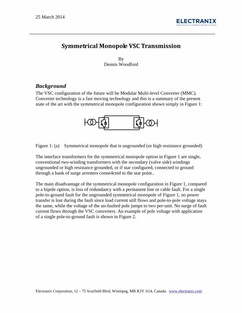
Figure 1: (a) Symmetrical monopole that is ungrounded (or high resistance grounded) The interface transformers for the symmetrical monopole option in Figure 1 are single, conventional two-winding transformers with the secondary (valve side) windings ungrounded or high resistance grounded, or if star configured, connected to ground through a bank of surge arresters conne4cted to the star point.. The main disadvantage of the symmetrical monopole configuration in Figure 1, compared to a bipole option, is loss of redundancy with a permanent line or cable fault. For a single pole-to-ground fault for the ungrounded symmetrical monopole of Figure 1, no power transfer is lost during the fault since load current still flows and pole-to-pole voltage stays the same, while the voltage of the un-faulted pole jumps to two per-unit. No surge of fault current flows through the VSC converters. An example of pole voltage with application of a single pole-to-ground fault is shown in Figure 2.
2
Figure 2: Impact of pole voltage on an ungrounded symmetrical VSC monopole with a
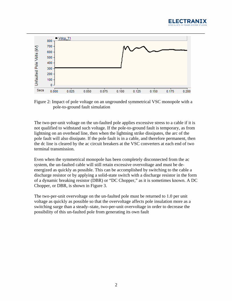
pole-to-ground fault simulation The two-per-unit voltage on the un-faulted pole applies excessive stress to a cable if it is not qualified to withstand such voltage. If the pole-to-ground fault is temporary, as from lightning on an overhead line, then when the lightning strike dissipates, the arc of the pole fault will also dissipate. If the pole fault is in a cable, and therefore permanent, then the dc line is cleared by the ac circuit breakers at the VSC converters at each end of two terminal transmission. Even when the symmetrical monopole has been completely disconnected from the ac system, the un-faulted cable will still retain excessive overvoltage and must be de-energized as quickly as possible. This can be accomplished by switching to the cable a discharge resistor or by applying a solid-state switch with a discharge resistor in the form of a dynamic breaking resistor (DBR) or “DC Chopper,” as it is sometimes known. A DC Chopper, or DBR, is shown in Figure 3. The two-per-unit overvoltage on the un-faulted pole must be returned to 1.0 per unit voltage as quickly as possible so that the overvoltage affects pole insulation more as a switching surge than a steady–state, two-per-unit overvoltage in order to decrease the possibility of this un-faulted pole from generating its own fault
3
Figure 3: Location of a DC Chopper in a VSC feeder If an ungrounded or high resistance grounded symmetrical MMC monopole is configured for an overhead dc line, it may be subject to frequent pole faults caused by lightning. After a time to allow for fault arc dissipation and de-ionization of the arc path, the DBR or chopper can quickly re-balance the pole voltages. No fault-clearing action by switches or circuit breakers is necessary, during which time dc power will continue to flow. This allows for the possibility that shield wires are unnecessary.
Half Bridge and Full Bridge Sub-modules The basic configurations of half bridge and full bridge sub-module that can be building blocks for an MMC converter are shown in Figure 4.
4
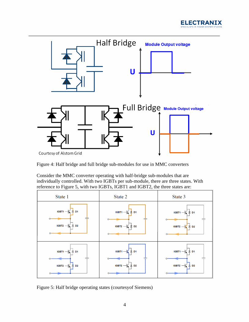
Figure 4: Half bridge and full bridge sub-modules for use in MMC converters Consider the MMC converter operating with half-bridge sub-modules that are individually controlled. With two IGBTs per sub-module, there are three states. With reference to Figure 5, with two IGBTs, IGBT1 and IGBT2, the three states are:
Figure 5: Half bridge operating states (courtesyof Siemens)
5
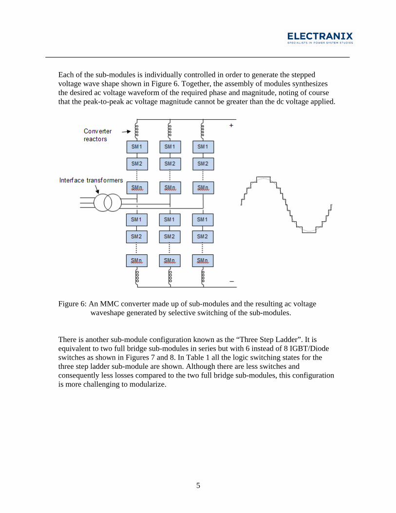
Each of the sub-modules is individually controlled in order to generate the stepped voltage wave shape shown in Figure 6. Together, the assembly of modules synthesizes the desired ac voltage waveform of the required phase and magnitude, noting of course that the peak-to-peak ac voltage magnitude cannot be greater than the dc voltage applied.
Figure 6: An MMC converter made up of sub-modules and the resulting ac voltage
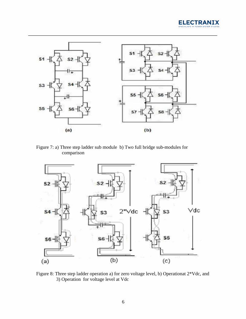
waveshape generated by selective switching of the sub-modules. There is another sub-module configuration known as the “Three Step Ladder”. It is equivalent to two full bridge sub-modules in series but with 6 instead of 8 IGBT/Diode switches as shown in Figures 7 and 8. In Table 1 all the logic switching states for the three step ladder sub-module are shown. Although there are less switches and consequently less losses compared to the two full bridge sub-modules, this configuration is more challenging to modularize.
6
Figure 7: a) Three step ladder sub module b) Two full bridge sub-modules for
comparison
Figure 8: Three step ladder operation a) for zero voltage level, b) Operationat 2*Vdc, and
3) Operation for voltage level at Vdc
7
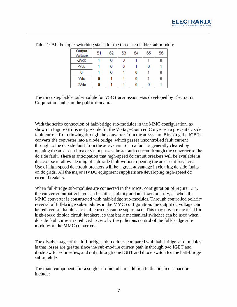
Table 1: All the logic switching states for the three step ladder sub-module
The three step ladder sub-module for VSC transmission was developed by Electranix Corporation and is in the public domain. With the series connection of half-bridge sub-modules in the MMC configuration, as shown in Figure 6, it is not possible for the Voltage-Sourced Converter to prevent dc side fault current from flowing through the converter from the ac system. Blocking the IGBTs converts the converter into a diode bridge, which passes uncontrolled fault current through to the dc side fault from the ac system. Such a fault is generally cleared by opening the ac circuit breakers that passes the ac fault current through the converter to the dc side fault. There is anticipation that high-speed dc circuit breakers will be available in due course to allow clearing of a dc side fault without opening the ac circuit breakers. Use of high-speed dc circuit breakers will be a great advantage in clearing dc side faults on dc grids. All the major HVDC equipment suppliers are developing high-speed dc circuit breakers. When full-bridge sub-modules are connected in the MMC configuration of Figure 13 4, the converter output voltage can be either polarity and not fixed polarity, as when the MMC converter is constructed with half-bridge sub-modules. Through controlled polarity reversal of full-bridge sub-modules in the MMC configuration, the output dc voltage can be reduced so that dc side fault currents can be suppressed. This may obviate the need for high-speed dc side circuit breakers, so that basic mechanical switches can be used when dc side fault current is reduced to zero by the judicious control of the full-bridge sub-modules in the MMC converters. The disadvantage of the full-bridge sub-modules compared with half-bridge sub-modules is that losses are greater since the sub-module current path is through two IGBT and diode switches in series, and only through one IGBT and diode switch for the half-bridge sub-module. The main components for a single sub-module, in addition to the oil-free capacitor, include:
8
1. IGBTs with reverse-biased diodes where two are required for the half bridge and four
for the full bridge, all mounted on water-cooled heat sinks 2. Protective thyristor usually for the half-bridge sub-module only 3. Gate drive units for the IGBTs 4. Fast mechanical by-pass switch across the terminals of the sub-module to short it out in
the event of a failure of an IGBT to open the circuit across the capacitor 5. Laminated conductors for low-inductance connections Full-bridge converters result in higher converter costs (approximately 20% more to the converter station) as compared to half–bridge, along with higher losses (approximately 1.3 to 1.2%, as compared to approximately 0.9% for half-bridge). There is the possibility to populate the valve arms in a VSC valve group with a combination of half-bridge and full-bridge sub-modules to lower DC voltage.
Protection of DC Systems with Symmetrical Monopole Converters A possibility for protection of DC systems with ungrounded or high resistance grounded symmetrical monopoles with half bridge sub-modules when they are subject to single pole to ground DC side faults, is a control action. The power flow through the DC system will continue with one pole faulted to ground but the DC side voltage will displace as shown in Figure 2 with the un-faulted pole at 2.0 per unit. The fault on the DC system can be cleared with opening of the AC circuit breakers at the converters feeding into the faulted cable section as mentioned above. If the DC system is a DC grid and the fault is a permanent one, then the AC breakers at all converters feeding into or out of the grid must open shutting down the grid. The faulted cable or line section is discriminated and cleared with mechanical switches at the faulted line section end. Then the remaining un-faulted sections of the grid can be brought back into operation by voltage rebalancing with DC choppers and the AC breakers reclosed and the possible power flows brought up. A non-permanent line fault may clear itself and all that is required after a de-ionizing time of about 200 milliseconds is to rebalance the voltages. If rebalancing is not possible because the fault is in a cable section or is permanent then this will be evident when the re-balancing is attempted and so the full protection measure with AC breaker openings at all converters required. Another option is to use DC circuit breakers to clear the faulted line section. For single pole to ground faults with ungrounded or high resistance ground symmetrical monopole grid systems, slower DC breaker configured as shown in Figure 9 can be used. They have been built and tested up to 500 kV and 4 kA and take about 70 milliseconds to clear the
9
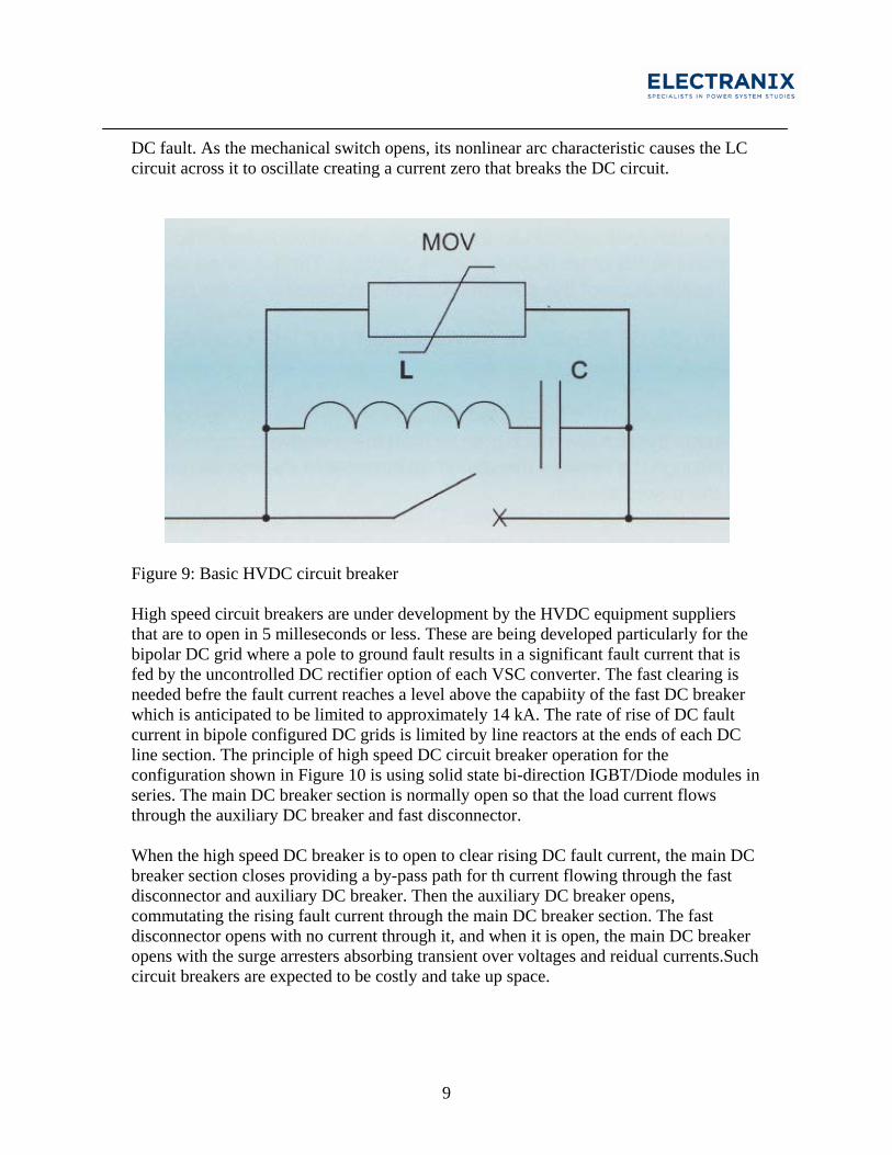
DC fault. As the mechanical switch opens, its nonlinear arc characteristic causes the LC circuit across it to oscillate creating a current zero that breaks the DC circuit.
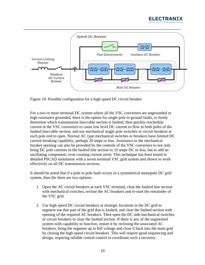
Figure 9: Basic HVDC circuit breaker High speed circuit breakers are under development by the HVDC equipment suppliers that are to open in 5 milleseconds or less. These are being developed particularly for the bipolar DC grid where a pole to ground fault results in a significant fault current that is fed by the uncontrolled DC rectifier option of each VSC converter. The fast clearing is needed befre the fault current reaches a level above the capabiity of the fast DC breaker which is anticipated to be limited to approximately 14 kA. The rate of rise of DC fault current in bipole configured DC grids is limited by line reactors at the ends of each DC line section. The principle of high speed DC circuit breaker operation for the configuration shown in Figure 10 is using solid state bi-direction IGBT/Diode modules in series. The main DC breaker section is normally open so that the load current flows through the auxiliary DC breaker and fast disconnector. When the high speed DC breaker is to open to clear rising DC fault current, the main DC breaker section closes providing a by-pass path for th current flowing through the fast disconnector and auxiliary DC breaker. Then the auxiliary DC breaker opens, commutating the rising fault current through the main DC breaker section. The fast disconnector opens with no current through it, and when it is open, the main DC breaker opens with the surge arresters absorbing transient over voltages and reidual currents.Such circuit breakers are expected to be costly and take up space.
10
Figure 10: Possible configuration for a high speed DC circuit breaker For a two or more terminal DC system where all the VSC converters are ungrounded or high resistance grounded, there is the option for single pole to ground faults, to firstly determine which transmission line/cable section is faulted, then quickly reschedule current in the VSC converters to cause low level DC current to flow in both poles of the faulted line/cable section, and use mechanical single pole switches or circuit breakers at each pole end to open. Normal AC type mechanical switches or breakers have limited DC current breaking capability, perhaps 20 amps or less. Assistance to the mechanical breaker opening can also be provided by the controls of the VSC converters to not only bring DC pole currents in the faulted line section to 10 amps DC or less, but to add an oscillating component, even creating current zeros. This technique has been tested in detailed PSCAD simulation with a seven terminal VSC grid system and shown to work effectively on all DC transmission sections. It should be noted that if a pole to pole fault occurs in a symmetrical monopole DC grid system, then the there are two options:
1. Open the AC circuit breakers at each VSC terminal, clear the faulted line section with mechanical switches, reclose the AC breakers and re-start the remainder of the VSC grid.
2. Use high speed DC circuit breakers at strategic locations in the DC grid to segment out that part of the grid that is faulted, and clear the faulted section with opening of the required AC breakers. Then open the DC side mechanical switches or circuit breakers to clear the faulted section. If there is any of the segmented system with capability to function, restart it by reclosing the associated AC breakers, bring the segment up to full voltage and close it back into the main grid by closing the high speed circuit breakers. This will require good sequencing and design, requiring reliable central control to coordinate such a recovery.
11
High Resistance Grounding of Symmetrical Monopoles There are a number of ways to affect high resistance grounding of symmetrical monopole converters can be configured. There are three considerations for selecting the value of the high resistance grounds. These are:
1. To keep the DC circuits balanced during normal steady state operation
2. To limit single pole fault current to a level that results in a low enough level that if the fault is from lightning on an overhead line, once the lightning dissipates, the fault arc from the conductor to tower cannot be sustained and will extinguish so that no mechanical switch operation is necessary, just voltage balancing with the DC choppers. In this way, DC power will flow uninterrupted.
3. When a converter is energized and brought on line, or faulted on the overhead line from lightning, that any dc zero sequence current on the ac connection between the converter and the unit transformer is not significant enough to saturate the transformer.
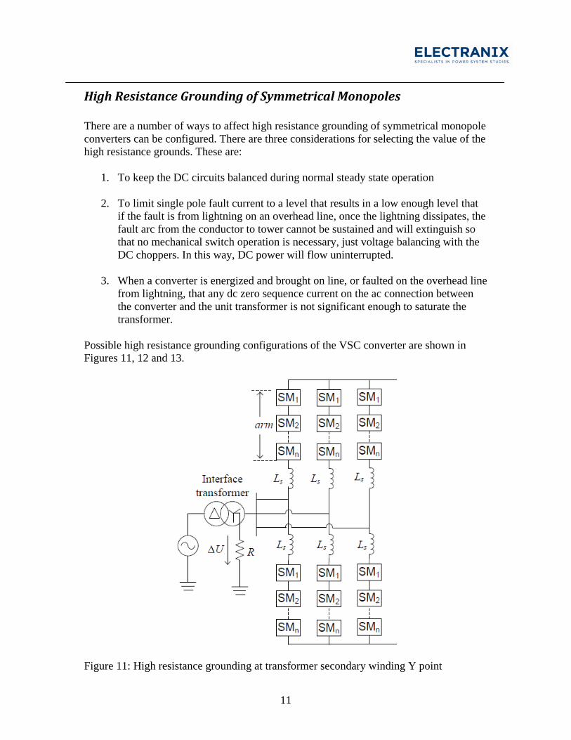
Possible high resistance grounding configurations of the VSC converter are shown in Figures 11, 12 and 13.
Figure 11: High resistance grounding at transformer secondary winding Y point
12
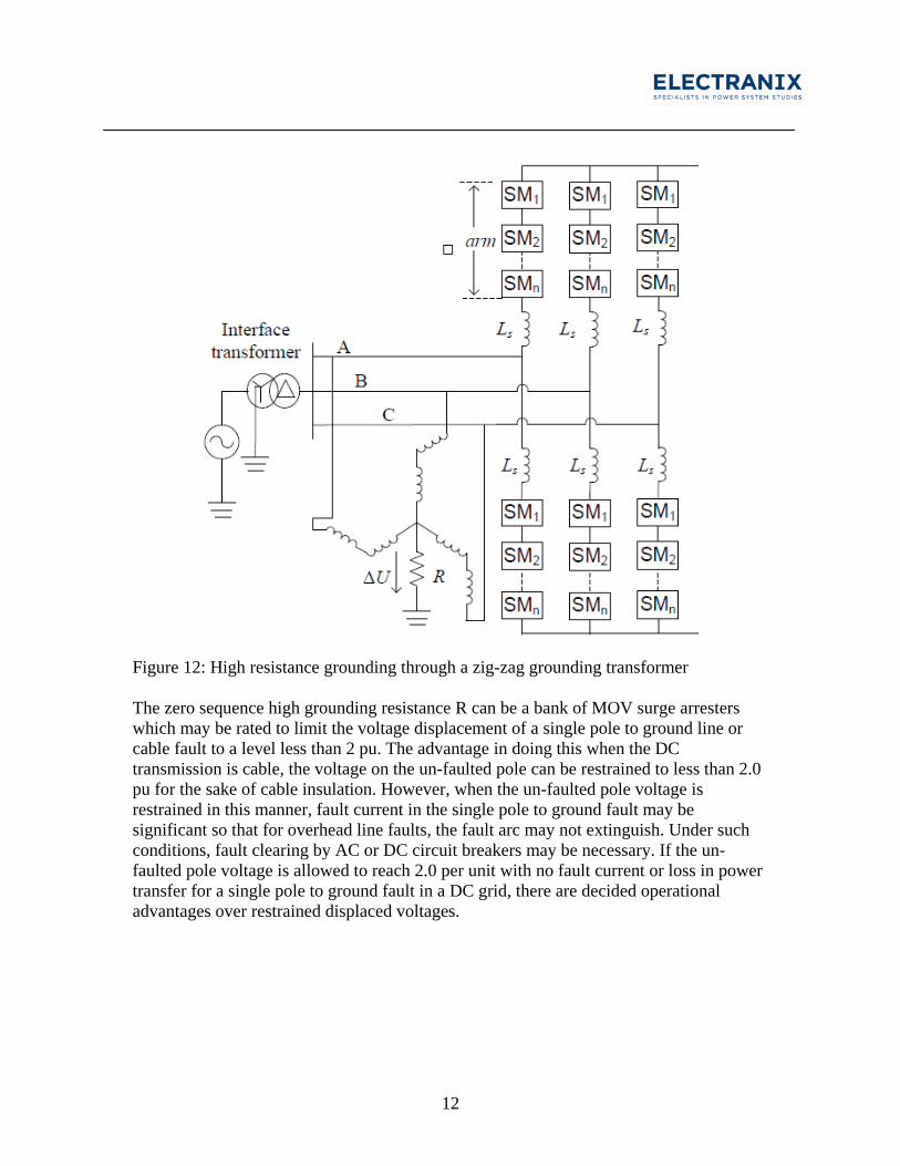
Figure 12: High resistance grounding through a zig-zag grounding transformer The zero sequence high grounding resistance R can be a bank of MOV surge arresters which may be rated to limit the voltage displacement of a single pole to ground line or cable fault to a level less than 2 pu. The advantage in doing this when the DC transmission is cable, the voltage on the un-faulted pole can be restrained to less than 2.0 pu for the sake of cable insulation. However, when the un-faulted pole voltage is restrained in this manner, fault current in the single pole to ground fault may be significant so that for overhead line faults, the fault arc may not extinguish. Under such conditions, fault clearing by AC or DC circuit breakers may be necessary. If the un-faulted pole voltage is allowed to reach 2.0 per unit with no fault current or loss in power transfer for a single pole to ground fault in a DC grid, there are decided operational advantages over restrained displaced voltages.
13
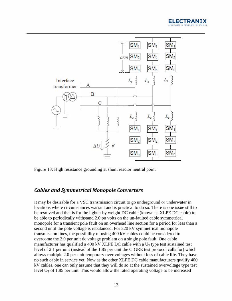
Figure 13: High resistance grounding at shunt reactor neutral point
Cables and Symmetrical Monopole Converters It may be desirable for a VSC transmission circuit to go underground or underwater in locations where circumstances warrant and is practical to do so. There is one issue still to be resolved and that is for the lighter by weight DC cable (known as XLPE DC cable) to be able to periodically withstand 2.0 pu volts on the un-faulted cable symmetrical monopole for a transient pole fault on an overhead line section for a period for less than a second until the pole voltage is rebalanced. For 320 kV symmetrical monopole transmission lines, the possibility of using 400 kV cables could be considered to overcome the 2.0 per unit dc voltage problem on a single pole fault. One cable manufacturer has qualified a 400 kV XLPE DC cable with a UT type test sustained test level of 2.1 per unit (instead of the 1.85 per unit the CIGRE test protocol calls for) which allows multiple 2.0 per unit temporary over voltages without loss of cable life. They have no such cable in service yet. Now as the other XLPE DC cable manufacturers qualify 400 kV cables, one can only assume that they will do so at the sustained overvoltage type test level UT of 1.85 per unit. This would allow the rated operating voltage to be increased
14
from 320 kV to 350 kV for a 400 kV cable so that the 2.0 per unit temporary overvoltage to 700 kV would pose no problem in aging a cable type tested to UT = 1.85 * 400 = 740 kV. 2.0 per unit of a 350 kV rated VSC system would be 700 kV, low enough below the 740 kV type test level to cause no aging problem with the cable for single pole faults to ground from environmental effects such as lightning. Otherwise for a 320 kV XLPE DC cable if it is qualified strictly to the CIGRE recommendations, the symmetrical monopole could be run at a lower voltage, say +/-280 kV which would lower the power transfer of the circuit accordingly unless the symmetrical monopole converters are designed to rapidly lower the DC voltage temporarily from 320 kV to 280 kV.
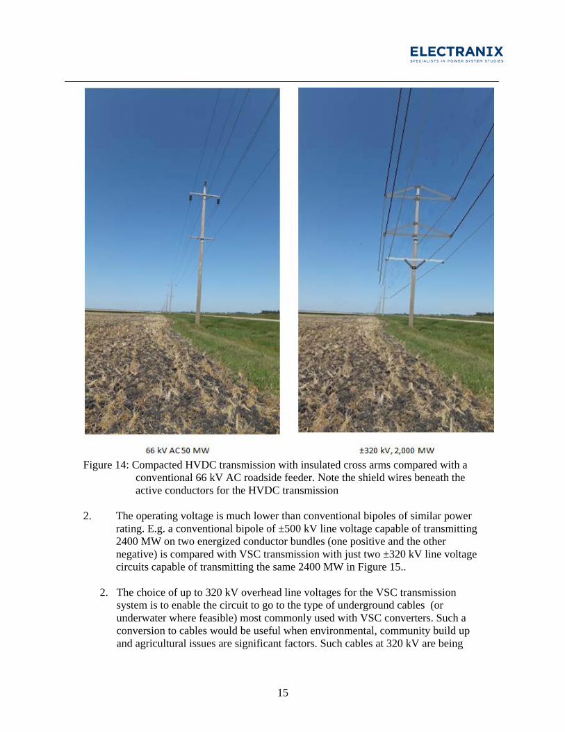
Compact DC with Symmetrical Monopoles There is a developing need to provide high voltage electric power transmission that minimizes impact on the environment, agriculture and communities. Overhead transmission lines have been the normal located on designated rights-of-way. Acquiring new right-of way for overhead ac transmission lines is usually challenging to permit and in some jurisdiction impossible to obtain. To minimize the adverse effects of high voltage electric power transmission lines, new technologies are forthcoming that when applied may be more acceptable. By judicious compacting of high voltage direct current (HVDC) and high voltage alternating current (HVAC) transmission systems, existing rights-of-way can be utilized, such as along roads or rail lines. A concept for compacting transmission lines for this purpose is presented. VSC converters with a symmetrical monopole have been successfully applied in many VSC undersea or underground HVDC transmission systems, but usually with restrained DC voltage excursion to less than 2.0 pu for the un-faulted pole. One compacted configuration of VSC transmission based on two symmetrical monopoles is shown in Figure 14, where it is about the same height as a roadside 66 kV AC feeder. In this case the symmetrical monopoles are ±320 kV with a total power rating of over 2000 MW to 2400 MW. The advantages of this two symmetrical monopole VSC transmission system shown in Figure 14 are:
1. A very large capacity transmission line has a low profile and can be used on existing rights-of-way as indicated in Figure 14. If essential 66 kV AC feeders are required and tolerated to supply electricity to rural communities, farms and industrial operations, then such a compact VSC transmission line should receive similar consideration. The permitting process for such an overhead high power transmission line should therefore take much less time
15
Figure 14: Compacted HVDC transmission with insulated cross arms compared with a
conventional 66 kV AC roadside feeder. Note the shield wires beneath the active conductors for the HVDC transmission
2. The operating voltage is much lower than conventional bipoles of similar power
rating. E.g. a conventional bipole of ±500 kV line voltage capable of transmitting 2400 MW on two energized conductor bundles (one positive and the other negative) is compared with VSC transmission with just two ±320 kV line voltage circuits capable of transmitting the same 2400 MW in Figure 15..
2. The choice of up to 320 kV overhead line voltages for the VSC transmission
system is to enable the circuit to go to the type of underground cables (or underwater where feasible) most commonly used with VSC converters. Such a conversion to cables would be useful when environmental, community build up and agricultural issues are significant factors. Such cables at 320 kV are being
16
qualified by cable manufacturers and one cable manufacturer has qualified this type of cable to 400 kV.
4. If necessary, the single pole towers can be constructed of sectionalized composite poles. Thus if vehicles or trucks or farm machinery crash into a tower its bottom section falls away and the top half of the tower is hangs from the conductors.
5. A significant benefit of an overhead HVDC symmetrical monopole line is that it
can be designed to be impervious to temporary line-to-tower faults or short circuits such as from a lightning fault direct onto a pole conductor. Power flow can be uninterrupted since such a fault can be self-clearing without any switching or power disruption
6. The transmission tower can be designed to add additional VSC symmetrical
monopole circuits by building a higher tower and adding the insulators and conductors beneath when needed.
7. No ground electrodes required. 8. Transformers required between the points of interconnection to the AC network
and the VSC converters require no special design as do conventional HVDC converter transformers.
9. Easy access for maintenance if located along a roadside
The main disadvantages of this compact HVDC line are:
1. The tower looks top heavy. 2. Costs for compact HVDC transmission may not be lower than the conventional
HVDC transmission lines perhaps because more towers are needed per mile (12 to 16 compact towers/mile compared to about 4 per mile for conventional HVDC towers). Losses must be taken into account when optimizing the 4 pole conductors and towers of the compact line possibly adding to cost.
3. Transmission line maintenance with one or both symmetrical monopoles
energized may require special consideration.
17
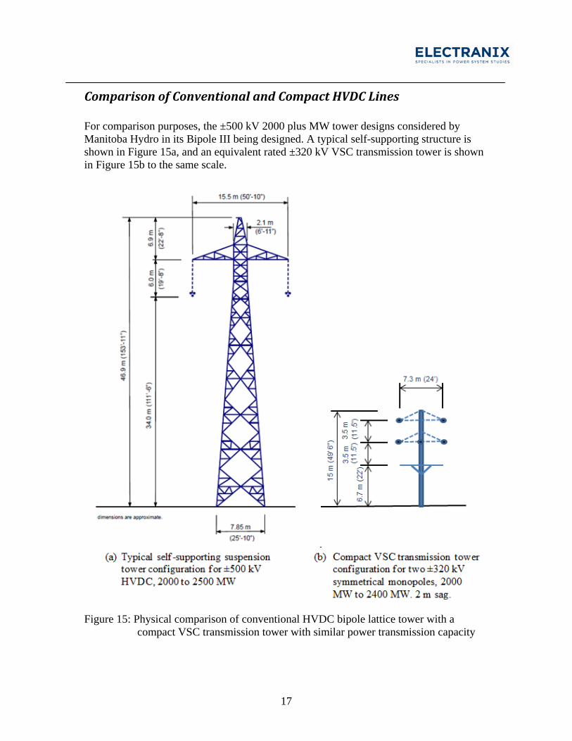
Comparison of Conventional and Compact HVDC Lines For comparison purposes, the ±500 kV 2000 plus MW tower designs considered by Manitoba Hydro in its Bipole III being designed. A typical self-supporting structure is shown in Figure 15a, and an equivalent rated ±320 kV VSC transmission tower is shown in Figure 15b to the same scale.
Figure 15: Physical comparison of conventional HVDC bipole lattice tower with a
compact VSC transmission tower with similar power transmission capacity
18
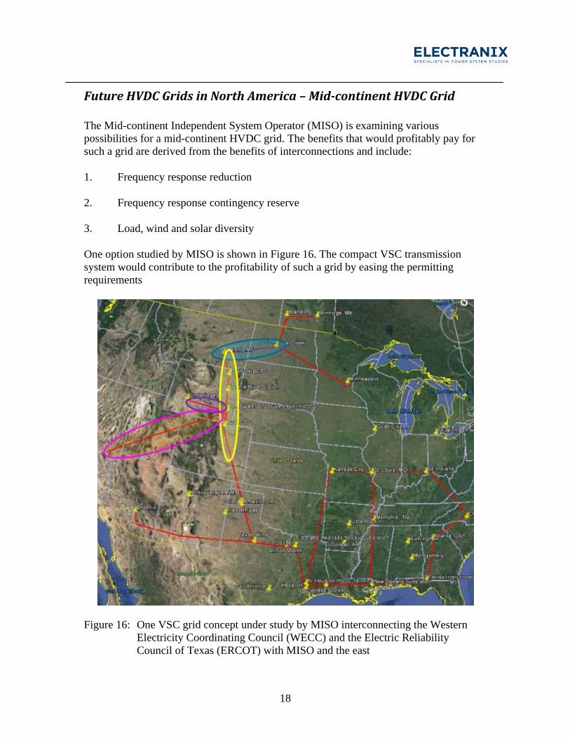
Future HVDC Grids in North America – Mid-continent HVDC Grid The Mid-continent Independent System Operator (MISO) is examining various possibilities for a mid-continent HVDC grid. The benefits that would profitably pay for such a grid are derived from the benefits of interconnections and include: 1. Frequency response reduction 2. Frequency response contingency reserve 3. Load, wind and solar diversity One option studied by MISO is shown in Figure 16. The compact VSC transmission system would contribute to the profitability of such a grid by easing the permitting requirements
Figure 16: One VSC grid concept under study by MISO interconnecting the Western
Electricity Coordinating Council (WECC) and the Electric Reliability Council of Texas (ERCOT) with MISO and the east
19
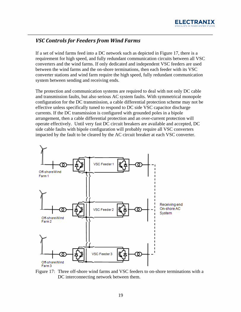
VSC Controls for Feeders from Wind Farms If a set of wind farms feed into a DC network such as depicted in Figure 17, there is a requirement for high speed, and fully redundant communication circuits between all VSC converters and the wind farms. If only dedicated and independent VSC feeders are used between the wind farms and the on-shore terminations, then each feeder with its VSC converter stations and wind farm require the high speed, fully redundant communication system between sending and receiving ends. The protection and communication systems are required to deal with not only DC cable and transmission faults, but also serious AC system faults. With symmetrical monopole configuration for the DC transmission, a cable differential protection scheme may not be effective unless specifically tuned to respond to DC side VSC capacitor discharge currents. If the DC transmission is configured with grounded poles in a bipole arrangement, then a cable differential protection and an over-current protection will operate effectively. Until very fast DC circuit breakers are available and accepted, DC side cable faults with bipole configuration will probably require all VSC converters impacted by the fault to be cleared by the AC circuit breaker at each VSC converter.
Figure 17: Three off-shore wind farms and VSC feeders to on-shore terminations with a
DC interconnecting network between them.
20
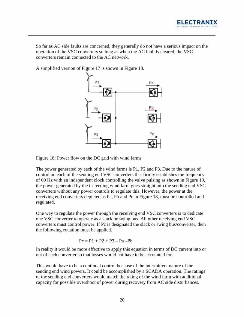
So far as AC side faults are concerned, they generally do not have a serious impact on the operation of the VSC converters so long as when the AC fault is cleared, the VSC converters remain connected to the AC network. A simplified version of Figure 17 is shown in Figure 18.
Figure 18: Power flow on the DC grid with wind farms The power generated by each of the wind farms is P1, P2 and P3. Due to the nature of control on each of the sending end VSC converters that firmly establishes the frequency of 60 Hz with an independent clock controlling the valve pulsing as shown in Figure 19, the power generated by the in-feeding wind farm goes straight into the sending end VSC converters without any power controls to regulate this. However, the power at the receiving end converters depicted as Pa, Pb and Pc in Figure 18, must be controlled and regulated. One way to regulate the power through the receiving end VSC converters is to dedicate one VSC converter to operate as a slack or swing bus. All other receiving end VSC converters must control power. If Pc is designated the slack or swing bus/converter, then the following equation must be applied. Pc = P1 + P2 + P3 – Pa –Pb
In reality it would be more effective to apply this equation in terms of DC current into or out of each converter so that losses would not have to be accounted for. This would have to be a continual control because of the intermittent nature of the sending end wind powers. It could be accomplished by a SCADA operation. The ratings of the sending end converters would match the rating of the wind farm with additional capacity for possible overshoot of power during recovery from AC side disturbances.
21
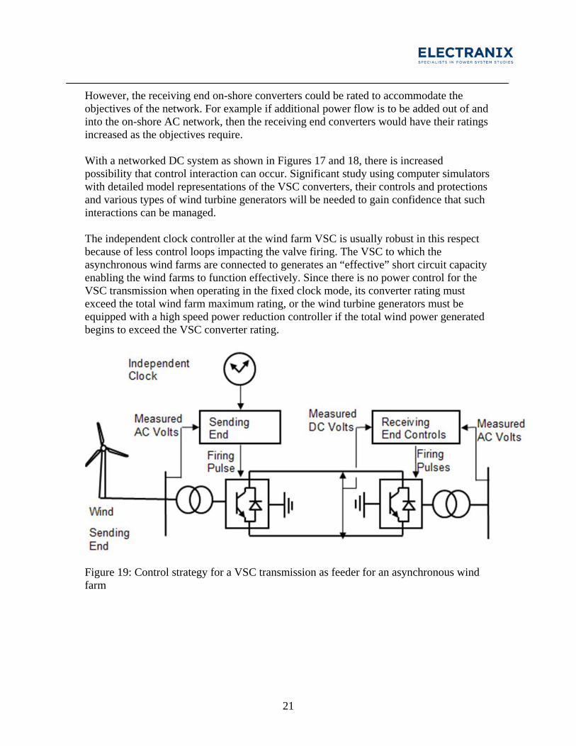
However, the receiving end on-shore converters could be rated to accommodate the objectives of the network. For example if additional power flow is to be added out of and into the on-shore AC network, then the receiving end converters would have their ratings increased as the objectives require. With a networked DC system as shown in Figures 17 and 18, there is increased possibility that control interaction can occur. Significant study using computer simulators with detailed model representations of the VSC converters, their controls and protections and various types of wind turbine generators will be needed to gain confidence that such interactions can be managed. The independent clock controller at the wind farm VSC is usually robust in this respect because of less control loops impacting the valve firing. The VSC to which the asynchronous wind farms are connected to generates an “effective” short circuit capacity enabling the wind farms to function effectively. Since there is no power control for the VSC transmission when operating in the fixed clock mode, its converter rating must exceed the total wind farm maximum rating, or the wind turbine generators must be equipped with a high speed power reduction controller if the total wind power generated begins to exceed the VSC converter rating.
Figure 19: Control strategy for a VSC transmission as feeder for an asynchronous wind farm
22
Conclusions The MMC symmetrical monopole converter with high resistance grounding offers decided advantages in HVDC transmission including improved performance through single pole to ground fault. A concept has been presented that provides a substantial reduction in HVDC high power transmission line profile using a compact design based on the VSC symmetrical monopole converter station configuration. The major benefit should be lower environmental impact and therefore shorter time to permit. Old transmission line design methods and thinking from 40 years ago must give way to the new and necessary requirement where multiple use rights-of-way have to be the focus for the future. As new right-of-way for overhead power transmission is becoming increasingly difficult and in some locations impossible to acquire, then the concepts presented herein become increasingly important. In fact, if a rigorous design effort is applied along with a change in transmission engineering culture, the concepts of transmission compaction proposed herein will open up new and exciting ways forward to benefit all.
References [1] “VSC Transmission,” CIGRE Brochure 269, Working Group B4.37, April 2005.
[2] J. Dorn, H. Huang, and D. Retzman, “Novel Voltage-Sourced Converters for HVDC and FACTS Applications,” CIGRE 2007 Osaka Symposium, Paper 314.
[3] Bidirectional Valves: Specific Practical Applications of Interest. EPRI, Palo Alto, CA, and Bonneville Power Administration, Vancouver, WA: 2005. Product ID # 007245.
[4] L.O. Barthold, D.A. Woodford, and W.F. Litzenberger, “Tripole Transmission with Voltage Sourced Converters,” CIGRE SC B4 2009 Colloquium, Bergen, Norway.
[5] M. P. Bahrman, W. F. Long, et al., “Integration of Small Taps into (Existing) HVDC Links,” IEEE Trans. on Power Delivery, Vol. 10, pp 1699-1706, July, 1995.
23
[6] G. Asplund, H. Hammarsten, R. Lagerup, and V. Lescale, “Small Series Tapping in HVDC Systems,” Proceedings of Symposium of Specialists in Electric Operational and Expansion Planning, Belo Horizonte, Brazil, May 1992.
[7] S. Hirano, J. Haraguchi, T. Mizuno, H. Niinobe, and Y. Nagoya, “Development of +/-250 kV Coaxially-Integrated Return Conductor Extruded Insulation Cable,” CIGRE 2007 Osaka Symposium, Paper 316.
[8] DC Capability of AC Transmission Lines. EPRI, Palo Alto, CA: 2008, Product ID Number 1013979.
[9] http://blogs.platts.com/2012/12/10/dc_breakthrough/
[10] Alstom Grid Brochure, “HVDC-VSC: Transmission Technology of the Future” http://www.alstom.com/Global/Grid/Resources/Documents/Smart%20Grid/HVDC-VSC%20transmission%20technology%20of%20the%20future%20-%20Think%20Grid%20n%C2%B08%20.pdf [11] Compact HVDC Transmission and its Field and Corona Effects. http://www.electranix.com/Papers/CompactHVDC.pdf http://www.electranix.com/pub_description.php?content=pub_13
![[PPT]PowerPoint Presentation - Electric Reliability Council · Web viewPresentation Overview Introduction to Electranix Background on Study Study Objectives Modeling Background Key](https://img.pdfslide.net/doc/110x75/5abec76a7f8b9ac0598d968d/pptpowerpoint-presentation-electric-reliability-council-viewpresentation.jpg)


![SYSTEM IMPACT STUDY FINAL REPORT · SYSTEM IMPACT STUDY – FINAL REPORT ELECTRANIX ii May 31 st, 2004 Studies using PSCAD (a 3-phase instantaneous solution simulation program [3])](https://img.pdfslide.net/doc/110x75/60395cab4ee4eb285c794765/system-impact-study-final-system-impact-study-a-final-report-electranix-ii-may.jpg)