Embed Size (px)
Citation preview
[email protected] T: 256-726-4838 www.synvivobio.com
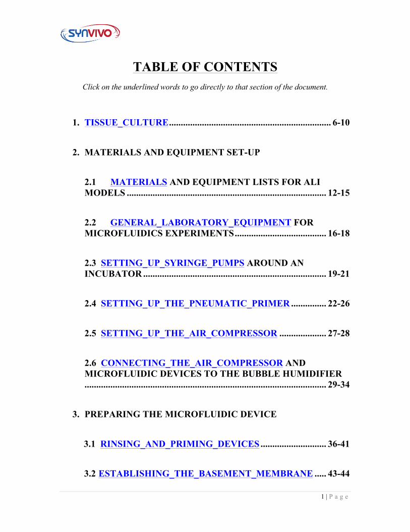
SynALI 3D Lung Model Using
Idealized Microvascular Network
1 | P a g e
TABLE OF CONTENTS Click on the underlined words to go directly to that section of the document.
1. TISSUE_CULTURE ..................................................................... 6-10
2. MATERIALS AND EQUIPMENT SET-UP 2.1 MATERIALS AND EQUIPMENT LISTS FOR ALI MODELS ..................................................................................... 12-15 2.2 GENERAL_LABORATORY_EQUIPMENT FOR MICROFLUIDICS EXPERIMENTS ....................................... 16-18
2.3 SETTING_UP_SYRINGE_PUMPS AROUND AN INCUBATOR .............................................................................. 19-21 2.4 SETTING_UP_THE_PNEUMATIC_PRIMER ............... 22-26 2.5 SETTING_UP_THE_AIR_COMPRESSOR .................... 27-28 2.6 CONNECTING_THE_AIR_COMPRESSOR AND MICROFLUIDIC DEVICES TO THE BUBBLE HUMIDIFIER....................................................................................................... 29-34
3. PREPARING THE MICROFLUIDIC DEVICE
3.1 RINSING_AND_PRIMING_DEVICES ............................ 36-41
3.2 ESTABLISHING_THE_BASEMENT_MEMBRANE ..... 43-44
2 | P a g e
4. PREPARING THE LUNG ALI MODEL
4.1 LUNG_ALI_MODEL TIMELINE AND MILESTONES
............................................................................................ 45-48
4.2 SEEDING_LUNG_EPITHELIAL_CELLS (MONOCULTURE) ......................................................... 49-53
4.3 CHANGING_THE_MEDIA IN A LUNG EPITHELIAL
MONOCULTURE ............................................................ 54-58
4.4 DIFFERENTIATION OF A LUNG EPITHELIAL MONOCULTURE (LIQUID_LIQUID_INTERFACE)…..59-62
4.5 DIFFERENTIATION OF A LUNG EPITHELIAL
MONOCULTURE (AIR_LIQUID_INTERFACE)…..63-68
4.6 RE_COATING_THE_MICROFLUIDIC_DEVICES FOR CO-CULTURE ESTABLISHMENT…………..69-72
4.7 SEEDING_LUNG_ENDOTHELIAL_CELLS TO
FORM A CO-CULTURE……………………………..73-76
4.8 CHANGING_THE_MEDIA_IN_A_LUNG_ALI CO-CULTURE…..77-78
5. ENDPOINT ASSAYS
3 | P a g e
5.1 EPITHELIAL_PERMEABILITY_ASSAY USING FITC-DEXTRAN ............................................................... …80-87 5.2 FIXING_CELLS_IN_THE_DEVICES ........................ 88-89 5.3 IMMUNOCYTOCHEMISTRY (ICC) STAINING ..... 90-93
4 | P a g e
Icons used in the Manual:
Hazard
Temperature Change
Time Sensitive
5 | P a g e
Section 1:
Tissue Culture
6 | P a g e
Tissue Culture Principle:
This protocol describes a general protocol for tissue culture used in the SynVivo lung ALI model.
Tissue culture conditions will change based on variations in donor lots, manufacturers or cell types. Please follow all manufacturer’s guidelines and media recommendations when establishing tissue culture.
Primary Cells or Cell Line(s): Obtain from desired commercial vendors
• Human Bronchial Epithelial Cells (HBE) • Human Microvascular Endothelial cells (HMVEC-L)
Reagents:
• Pneumacult EX Media (StemCell Technologies 05008) • Trypsin-EDTA (0.05%), with phenol red (ThermoFisher Scientific 25300054) • Defined trypsin inhibitor (ThermoFisher Scientific R007100) • HEPES buffered saline (Lonza CC-5022) • 1X PBS without calcium or magnesium (Corning 21040CV) • Dimethyl sulfoxide, Bioreagent (DMSO; Sigma Aldrich D8418-50ML) • Fetal bovine serum, heat inactivated (HI-FBS) • EGM-2MV endothelial basal media and bullet kit (Lonza CC-3202) • 1X PBS without calcium or magnesium (Corning 21040CV)
Equipment:
• T75 flasks (Corning 430641), or other flask size; tissue culture treated • Tissue culture incubator • 15-ml conical tubes, sterile • 50-ml conical tubes, sterile • Centrifuge
7 | P a g e
HMVEC-L Thawing and Cell Propagation Protocol: Adherent or suspension: Cells are adherent. Growth Media: EGM-2MV Bullet Kit (Lonza CC-3202) Flask coating required: None Freeze Media: Complete endothelial medium with 10% (v/v) DMSO &
10% (v/v) HI-FBS The following protocols should be carried out within a laminar flow hood as much as possible to maintain sterility. Thawing and seeding endothelial cells: Note: This protocol will describe how to expand the HMVEC-Ls for both experimental purposes and for freezing down the cells. Depending on where the HMVEC-Ls are purchased from, follow the manufacturer’s recommendations for culturing, preparing the freezing media, and cryopreservation. 1. The recommended seeding density for HMVEC-L is 5,000 cells/cm2. 2. To set up cultures, calculate the number of vessels needed based on the recommended
seeding density and the surface area of the vessels being used. Do not seed cells directly into a well plate directly out of cryopreservation. Add the appropriate amount of medium to the vessels (1 ml/5 cm2) and allow the vessels to equilibrate in a 37°C, 5% CO 2, humidified incubator for at least 30 minutes.
3. Wipe cryovial with ethanol or isopropanol before opening. In a sterile field, briefly twist the cap a quarter turn to relieve pressure, and then retighten. Quickly thaw the cryovial in a 37°C water bath being careful not to submerge the entire vial. Watch your cryovial closely; when the last sliver of ice melts, remove it. Do not submerge it completely. Thawing the cells for longer than 2 minutes results in less than optimal results.
4. Resuspend the cells in the cryovial and using a micropipette, dispense cells into the culture vessels set up earlier. Gently rock the culture vessel to evenly distribute the cells and return to the incubator.
5. Centrifugation should not be performed to remove cells from cryoprotectant cocktail. This action is more damaging than the effects of DMSO residue in the culture.
6. Incubate the cells overnight in a tissue culture incubator at 37°C, 5% CO2. 7. Change the media the next day.
8 | P a g e
8. Change media according to the manufacturer’s recommendations until the flask becomes confluent (70-80% coverage). Don’t let the flask become too confluent, or else the cells will dissociate in large patches instead of as individual cells.
Dissociating endothelial cells from the flask: 1. Remove and discard the endothelial cell media from the T75 flask of endothelial
cells. 2. Rinse the endothelial cells twice with room temperature 1X PBS or HEPES buffered
saline. a. Gently rock the flask in between rinses. b. Remove final rinse and discard.
3. Add 3 mL of room 0.05% Trypsin-EDTA to the flask. 4. Incubate flask at 37°C for 5−7 minutes. 5. Add 3 mL of defined trypsin inhibitor to the flask to neutralize the dissociation
reagent. 6. Gently wash the sides of the flask to remove the adherent cells. 7. Pellet the cells by centrifugation.
a. Use 200 x g (1000 RPM) for 5−10 minutes at room temperature (do not use speeds greater than 1000 RPM).
8. Remove the media, leaving behind at least 100 µl to cover the cell pellet. 9. Wash the cells twice with 5 mL complete endothelial cell media, and pellet the cells
by centrifugation. a. Use 200 x g for 5−10 minutes at room temperature (do not use speeds greater
than 1000 RPM). 10. Seed the cells or split according to the manufacturer’s guidelines. HBE Thawing and Cell Propagation Protocol: Adherent or suspension: Cells are adherent. Growth Media: Pneumacult EX (StemCell Technologies) Flask coating required: None Freeze Media: Complete epithelial medium with 10% (v/v) DMSO The following protocols should be carried out within a laminar flow hood as much as possible to maintain sterility. Thawing and seeding epithelial cells:
9 | P a g e
Note: This protocol will describe how to expand the HBEs for both experimental purposes and for freezing down the cells. Depending on where the HBEs are purchased from, follow the manufacturer’s recommendations for culturing, preparing the freezing media, and cryopreservation. 1. The recommended seeding density for HBE is 3,500 cells/cm2. 2. To set up cultures, calculate the number of vessels needed based on the
recommended seeding density and the surface area of the vessels being used. Do not seed cells directly into a well plate directly out of cryopreservation. Add the appropriate amount of medium to the vessels (1 ml/5 cm2) and allow the vessels to equilibrate in a 37°C, 5% CO 2, humidified incubator for at least 30 minutes.
3. Wipe cryovial with ethanol or isopropanol before opening. In a sterile field, briefly twist the cap a quarter turn to relieve pressure, and then retighten. Quickly thaw the cryovial in a 37°C water bath being careful not to submerge the entire vial. Watch your cryovial closely; when the last sliver of ice melts, remove it. Do not submerge it completely. Thawing the cells for longer than 2 minutes results in less than optimal results.
4. Resuspend the cells in the cryovial and using a micropipette, dispense cells into the culture vessels set up earlier. Gently rock the culture vessel to evenly distribute the cells and return to the incubator.
5. Centrifugation should not be performed to remove cells from cryoprotectant cocktail. This action is more damaging than the effects of DMSO residue in the culture.
6. Incubate the cells overnight in a tissue culture incubator at 37°C, 5% CO2. 7. Change the media the next day. 8. Change media according to the manufacturer’s recommendations until the flask
becomes confluent (70-80% coverage). a. Don’t let the flask become too confluent, or else the cells
will dissociate in large patches instead of as individual cells.
Dissociating epithelial cells from the flask: 1. Remove and discard the epithelial cell media from the T75 flask. 2. Rinse the epithelial cells twice with room temperature 1X PBS or HEPES buffered
saline. a. Gently rock the flask in between rinses. b. Remove final rinse and discard.
3. Add 5 mL of room temp 0.05% Trypsin-EDTA to the flask. 4. Incubate flask at 37°C for 5−7 minutes (Note: some cell types may take longer.)
10 | P a g e
5. Add 5 mL of defined trypsin inhibitor to the flask to neutralize the dissociation reagent.
6. Gently wash the sides of the flask to remove the adherent cells. 7. Pellet the cells by centrifugation.
a. Use 200 x g (1000 RPM) for 5−10 minutes at room temperature (do not use speeds greater than 1000 RPM).
8. Remove the media, leaving behind at least 100 µl to cover the cell pellet. 9. Wash the cells twice with 5 mL complete epithelial cell media, and pellet the cells
by centrifugation. a. Use 200 x g for 5−10 minutes at room temperature (do not
use speeds greater than 1000 RPM). 10. Seed the cells or split according to the manufacturer’s guidelines
11 | P a g e
Section 2:
Materials and
Equipment Set-up
12 | P a g e
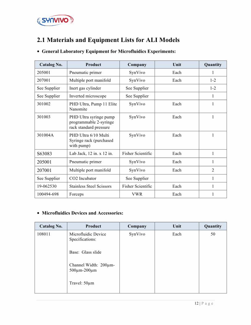
2.1 Materials and Equipment Lists for ALI Models
• General Laboratory Equipment for Microfluidics Experiments:
Catalog No. Product Company Unit Quantity
205001 Pneumatic primer SynVivo Each 1
207001 Multiple port manifold SynVivo Each 1-2
See Supplier Inert gas cylinder See Supplier 1-2
See Supplier Inverted microscope See Supplier 1
301002 PHD Ultra, Pump 11 Elite Nanomite
SynVivo Each 1
301003 PHD Ultra syringe pump programmable 2-syringe rack standard pressure
SynVivo Each 1
301004A PHD Ultra 6/10 Multi Syringe rack (purchased with pump)
SynVivo Each 1
S63083 Lab Jack, 12 in. x 12 in. Fisher Scientific Each 1
205001 Pneumatic primer SynVivo Each 1
207001 Multiple port manifold SynVivo Each 2
See Supplier CO2 Incubator See Supplier 1
19-062530 Stainless Steel Scissors Fisher Scientific Each 1
100494-698 Forceps VWR Each 1
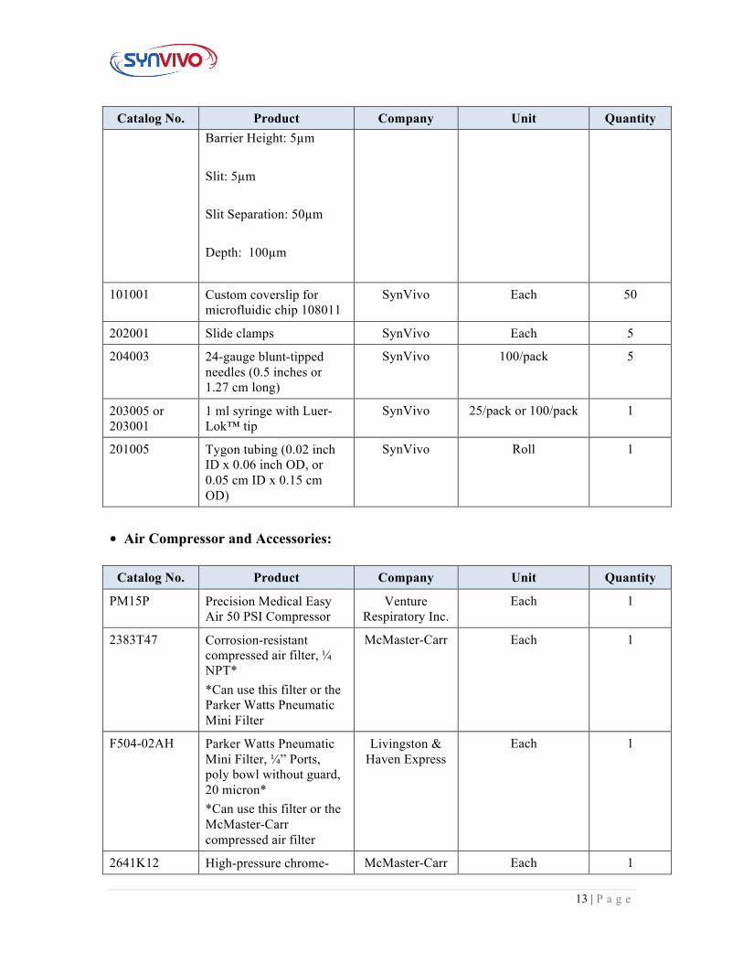
• Microfluidics Devices and Accessories:
Catalog No. Product Company Unit Quantity
108011 Microfluidic Device Specifications: Base: Glass slide Channel Width: 200µm-500µm-200µm Travel: 50µm
SynVivo Each 50
13 | P a g e
Catalog No. Product Company Unit Quantity Barrier Height: 5µm Slit: 5µm Slit Separation: 50µm Depth: 100µm
101001 Custom coverslip for microfluidic chip 108011
SynVivo Each 50
202001 Slide clamps SynVivo Each 5
204003 24-gauge blunt-tipped needles (0.5 inches or 1.27 cm long)
SynVivo 100/pack 5
203005 or 203001
1 ml syringe with Luer-Lok™ tip
SynVivo 25/pack or 100/pack 1
201005 Tygon tubing (0.02 inch ID x 0.06 inch OD, or 0.05 cm ID x 0.15 cm OD)
SynVivo Roll 1
• Air Compressor and Accessories:
Catalog No. Product Company Unit Quantity
PM15P Precision Medical Easy Air 50 PSI Compressor
Venture Respiratory Inc.
Each 1
2383T47 Corrosion-resistant compressed air filter, ¼ NPT* *Can use this filter or the Parker Watts Pneumatic Mini Filter
McMaster-Carr Each 1
F504-02AH Parker Watts Pneumatic Mini Filter, ¼” Ports, poly bowl without guard, 20 micron* *Can use this filter or the McMaster-Carr compressed air filter
Livingston & Haven Express
Each 1
2641K12 High-pressure chrome- McMaster-Carr Each 1
14 | P a g e
Catalog No. Product Company Unit Quantity plated brass pipe fitting, 90 degree elbow connector, ¼ NPTF female
4830K132 Standard-Wall 304/304L stainless steel pipe nipple, threaded on both ends, ¼ NPT, 1-1/2” Long
McMaster-Carr Each 2
50925K541 Compact extreme-pressure steel pipe fitting, straight adapter, 9/16”-18 UNF female x ¼ NPTF male
McMaster-Carr Each 1
2641K16 High-pressure chrome-plated brass pipe fitting, 90 degree elbow adapter, ¼ NPTF female x male
McMaster-Carr Each 1
5779K131 Push-to-connect tube fitting for air, straight adapter, for ¼” tube OD x ¼ NPT female
McMaster-Carr Each 1
46425K22 Easy-Set Precision Flow-Adjustment Valve, Steel Body with Fluorocarbon Rubber Seal, ¼ NPTF female
McMaster-Carr Each 1
UX-08270-33 PTFE thread tape (plumber’s)
Cole-Parmer Each 1
41695K31 Flowmeter for water, 0.002 ml/min to 1.1 ml min flow range
McMaster-Carr Each 1
Optional parts:
PIF25-14-PP-5
¼ inch (0.635 cm) outer diameter Push-in Serviceable Filter
Industrial Specialties
Mfg.
Each 1
15 | P a g e
• Air Compressor-To-Chip Interface with Bubble Humidifier:
Catalog No. Product Company Unit Quantity
2129T16 FEP clear tubing for chemicals, 1/8” ID, ¼” OD
McMaster-Carr 25 ft. 1
51525K123 Plastic Quick-Turn tube coupling, plugs, for 1/8” barbed tube ID, nylon
McMaster-Carr 10/pack 1
51525K211 Plastic Quick-Turn tube coupling, sockets, for 1/16” barbed tube ID, nylon
McMaster-Carr 10/pack 1
51525K121 Plastic Quick-Turn tube coupling, plugs, for 1/16” barbed tube ID, nylon
McMaster-Carr 10/pack 1
5648K67 Firm polyurethane tubing for air and water, 1/16” ID, 1/8” OD, clear
McMaster-Carr 25 ft. 1
14395-100 Media bottle with cap, 100 ml
VWR 10 bottles/case 1
A-620 Bottle cap assembly, for 1/8 in. tubing OD
IDEX Health & Science Each 3
64-0212 MPP Series (MPP-2) perfusion mini-manifold, 2 to 1 port
WarnerOnline Each 2
64-0213 MPP Series (MPP-3) perfusion mini-manifold, 3 to 1 port
WarnerOnline Each 4
32829-024 HelixMark® peristaltic pump silicone tubing, 0.031” ID x 0.157” OD, 0.063” wall thickness
VWR 25 ft. 1
Optional parts:
1109 IncuTherm Plus Digital Thermometer/Hygrometer with remote probe
IncubatorWarehouse.com Each 1
16 | P a g e
2.2 General Laboratory Equipment for Microfluidics Experiments
Principle:
In addition to the microfluidics devices, the following list describes the general laboratory equipment needed to run microfluidics experiments using the SynVivo platform. For a description of the ALI set-up, see following sections.
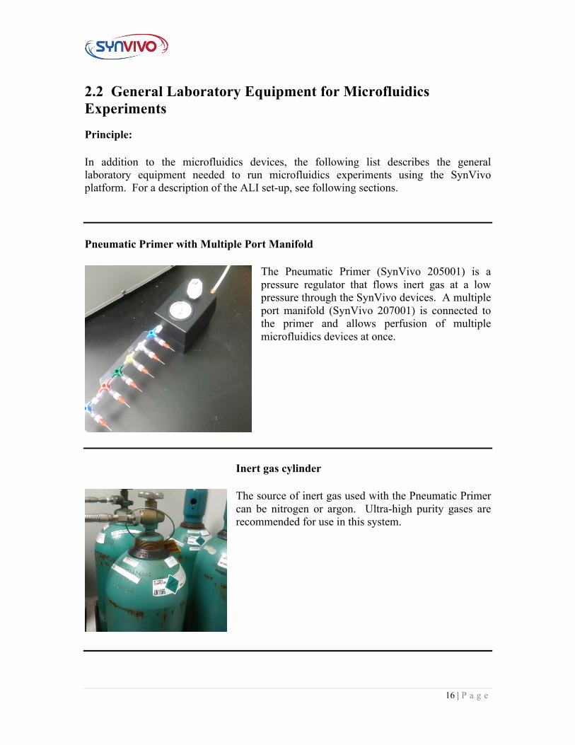
Pneumatic Primer with Multiple Port Manifold
The Pneumatic Primer (SynVivo 205001) is a pressure regulator that flows inert gas at a low pressure through the SynVivo devices. A multiple port manifold (SynVivo 207001) is connected to the primer and allows perfusion of multiple microfluidics devices at once.
Inert gas cylinder
The source of inert gas used with the Pneumatic Primer can be nitrogen or argon. Ultra-high purity gases are recommended for use in this system.
17 | P a g e
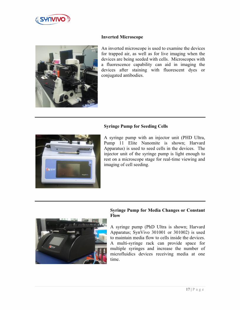
Inverted Microscope
An inverted microscope is used to examine the devices for trapped air, as well as for live imaging when the devices are being seeded with cells. Microscopes with a fluorescence capability can aid in imaging the devices after staining with fluorescent dyes or conjugated antibodies.
Syringe Pump for Seeding Cells
A syringe pump with an injector unit (PHD Ultra, Pump 11 Elite Nanomite is shown; Harvard Apparatus) is used to seed cells in the devices. The injector unit of the syringe pump is light enough to rest on a microscope stage for real-time viewing and imaging of cell seeding.
Syringe Pump for Media Changes or Constant Flow
A syringe pump (PhD Ultra is shown; Harvard Apparatus; SynVivo 301001 or 301002) is used to maintain media flow to cells inside the devices. A multi-syringe rack can provide space for multiple syringes and increase the number of microfluidics devices receiving media at one time.
18 | P a g e
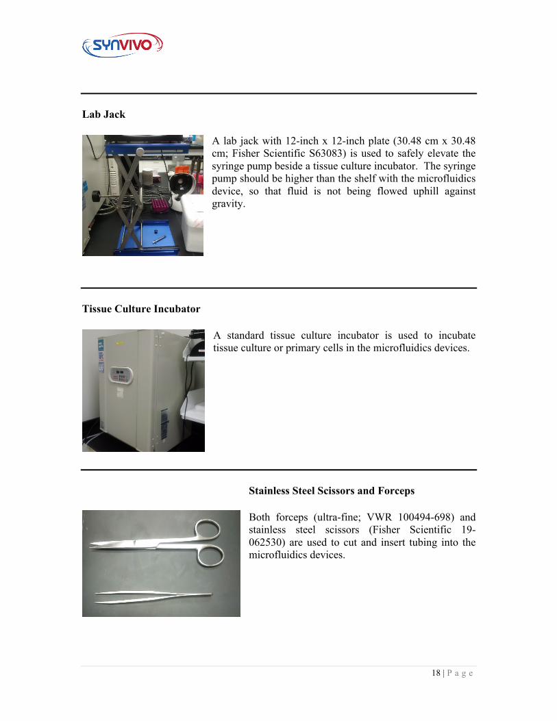
Lab Jack
A lab jack with 12-inch x 12-inch plate (30.48 cm x 30.48 cm; Fisher Scientific S63083) is used to safely elevate the syringe pump beside a tissue culture incubator. The syringe pump should be higher than the shelf with the microfluidics device, so that fluid is not being flowed uphill against gravity.
Tissue Culture Incubator
A standard tissue culture incubator is used to incubate tissue culture or primary cells in the microfluidics devices.
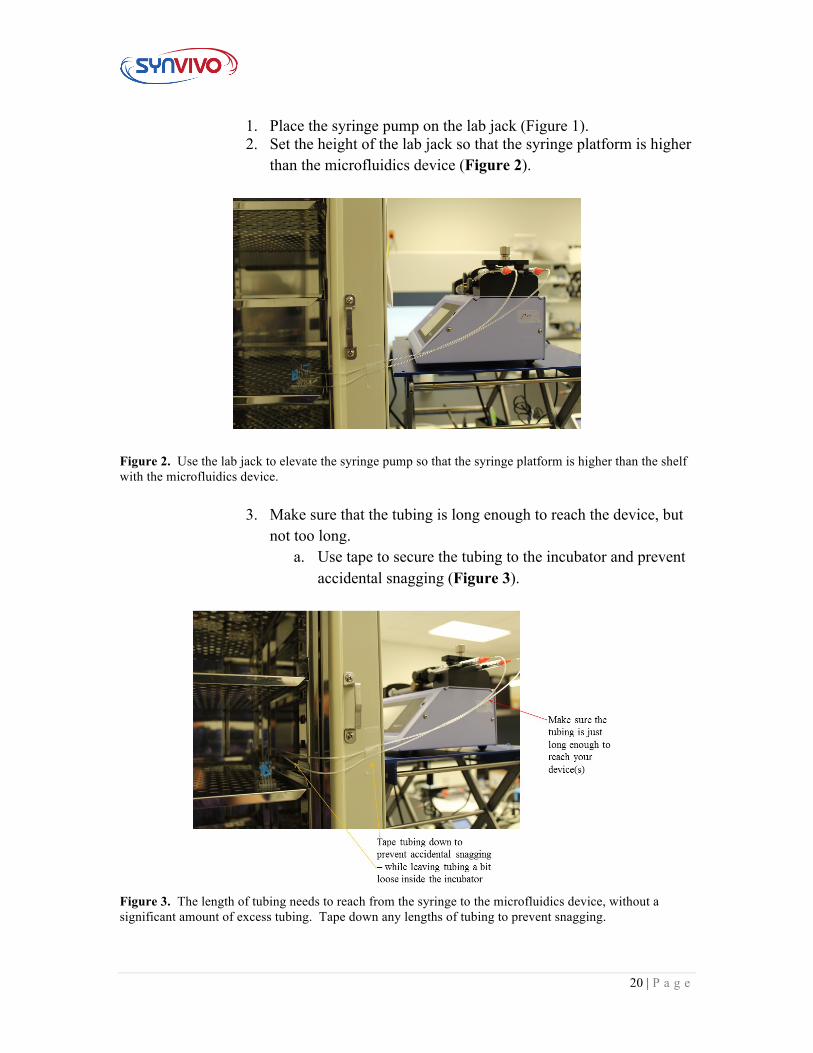
Stainless Steel Scissors and Forceps
Both forceps (ultra-fine; VWR 100494-698) and stainless steel scissors (Fisher Scientific 19-062530) are used to cut and insert tubing into the microfluidics devices.
19 | P a g e
2.3 Setting Up Syringe Pumps Around an Incubator Principle:
The following protocol describes some of the best methods to set up a syringe pump beside a tissue culture incubator. The important considerations to keep in mind include minimizing the length of the tubing between the syringe pump and the device, as well as making the syringe pump easily accessible to the user.
Equipment:
• SynVivo microfluidics device • Tygon tubing (0.02 inch ID x 0.06 inch OD, or 0.05 cm ID x 0.15 cm OD;
SynVivo 201005) • Slide clamps (SynVivo 202001) • 1 mL syringe with Luer-Lok tip (25 pack; SynVivo 203005) • 24-gauge blunt-tipped needles (0.5 inches or 1.27 cm long; SynVivo 204003) • Pneumatic Primer (SynVivo 205001) • Forceps (ultra-fine; VWR 100494-698) • Stainless steel scissors (Fisher Scientific 19-062530) • Syringe pump (PhD Ultra; Harvard Apparatus; SynVivo 301001 or 301002) • Lab jack with 12-inch x 12-inch plate (30.48 cm x 30.48 cm; Fisher Scientific
S63083) • Tissue culture incubator
Reagents:
• Cell culture media
Protocol:
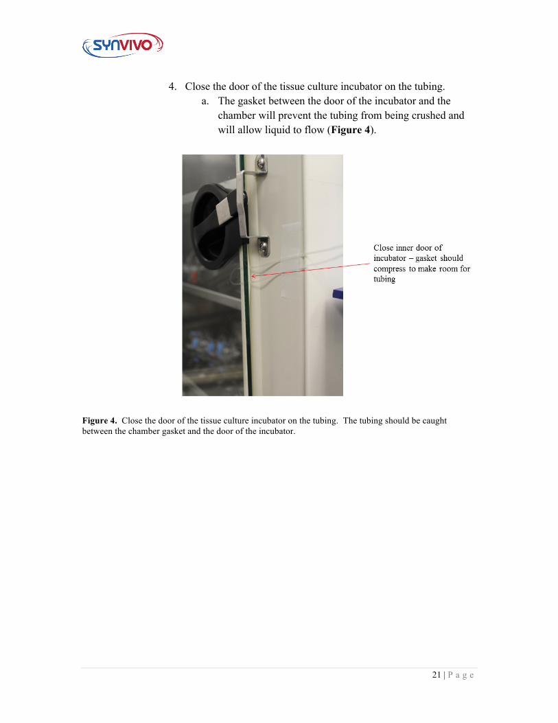
Figure 1. A syringe pump on a lab jack (right) is connected to a microfluidics device in a tissue culture incubator (left).
20 | P a g e
1. Place the syringe pump on the lab jack (Figure 1). 2. Set the height of the lab jack so that the syringe platform is higher
than the microfluidics device (Figure 2).
Figure 2. Use the lab jack to elevate the syringe pump so that the syringe platform is higher than the shelf with the microfluidics device.
3. Make sure that the tubing is long enough to reach the device, but
not too long. a. Use tape to secure the tubing to the incubator and prevent
accidental snagging (Figure 3).
Figure 3. The length of tubing needs to reach from the syringe to the microfluidics device, without a significant amount of excess tubing. Tape down any lengths of tubing to prevent snagging.
21 | P a g e
4. Close the door of the tissue culture incubator on the tubing. a. The gasket between the door of the incubator and the
chamber will prevent the tubing from being crushed and will allow liquid to flow (Figure 4).
Figure 4. Close the door of the tissue culture incubator on the tubing. The tubing should be caught between the chamber gasket and the door of the incubator.
22 | P a g e
2.4 Setting up the Pneumatic Primer
Principle:
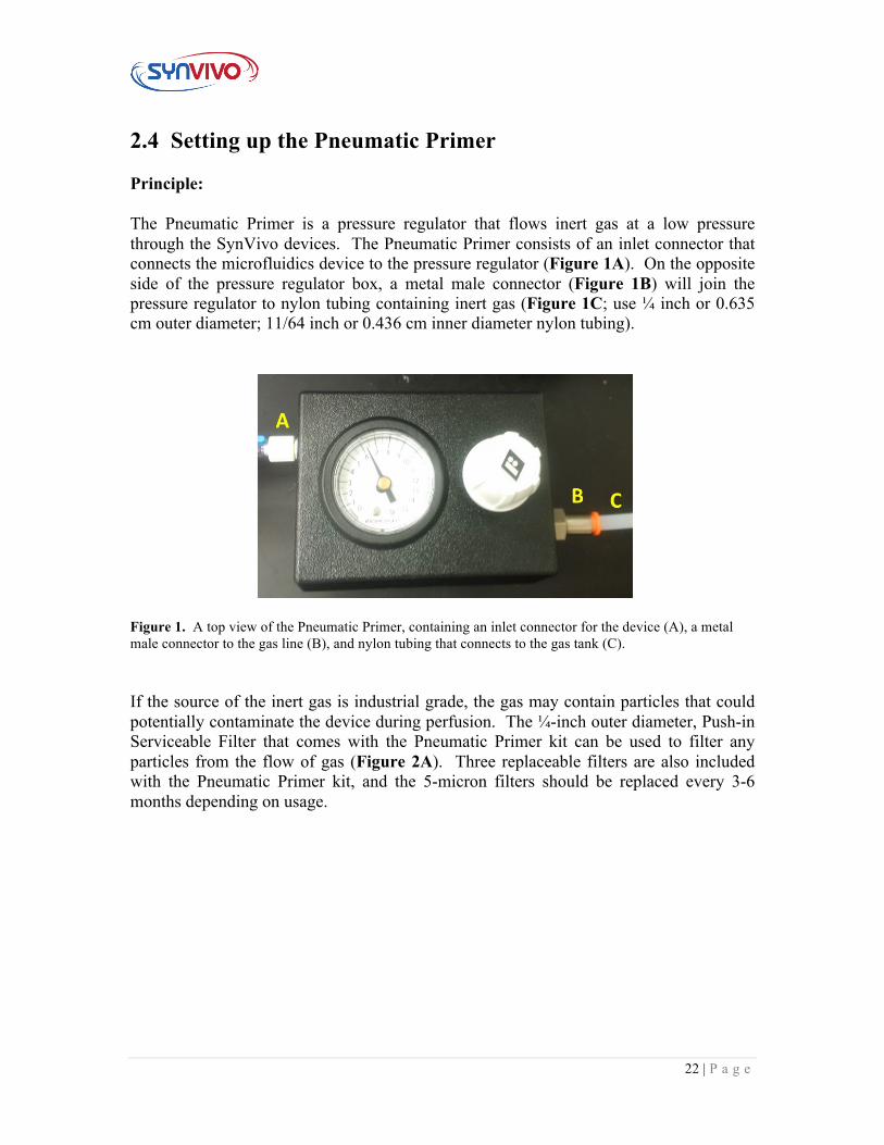
The Pneumatic Primer is a pressure regulator that flows inert gas at a low pressure through the SynVivo devices. The Pneumatic Primer consists of an inlet connector that connects the microfluidics device to the pressure regulator (Figure 1A). On the opposite side of the pressure regulator box, a metal male connector (Figure 1B) will join the pressure regulator to nylon tubing containing inert gas (Figure 1C; use ¼ inch or 0.635 cm outer diameter; 11/64 inch or 0.436 cm inner diameter nylon tubing).
Figure 1. A top view of the Pneumatic Primer, containing an inlet connector for the device (A), a metal male connector to the gas line (B), and nylon tubing that connects to the gas tank (C). If the source of the inert gas is industrial grade, the gas may contain particles that could potentially contaminate the device during perfusion. The ¼-inch outer diameter, Push-in Serviceable Filter that comes with the Pneumatic Primer kit can be used to filter any particles from the flow of gas (Figure 2A). Three replaceable filters are also included with the Pneumatic Primer kit, and the 5-micron filters should be replaced every 3-6 months depending on usage.
23 | P a g e
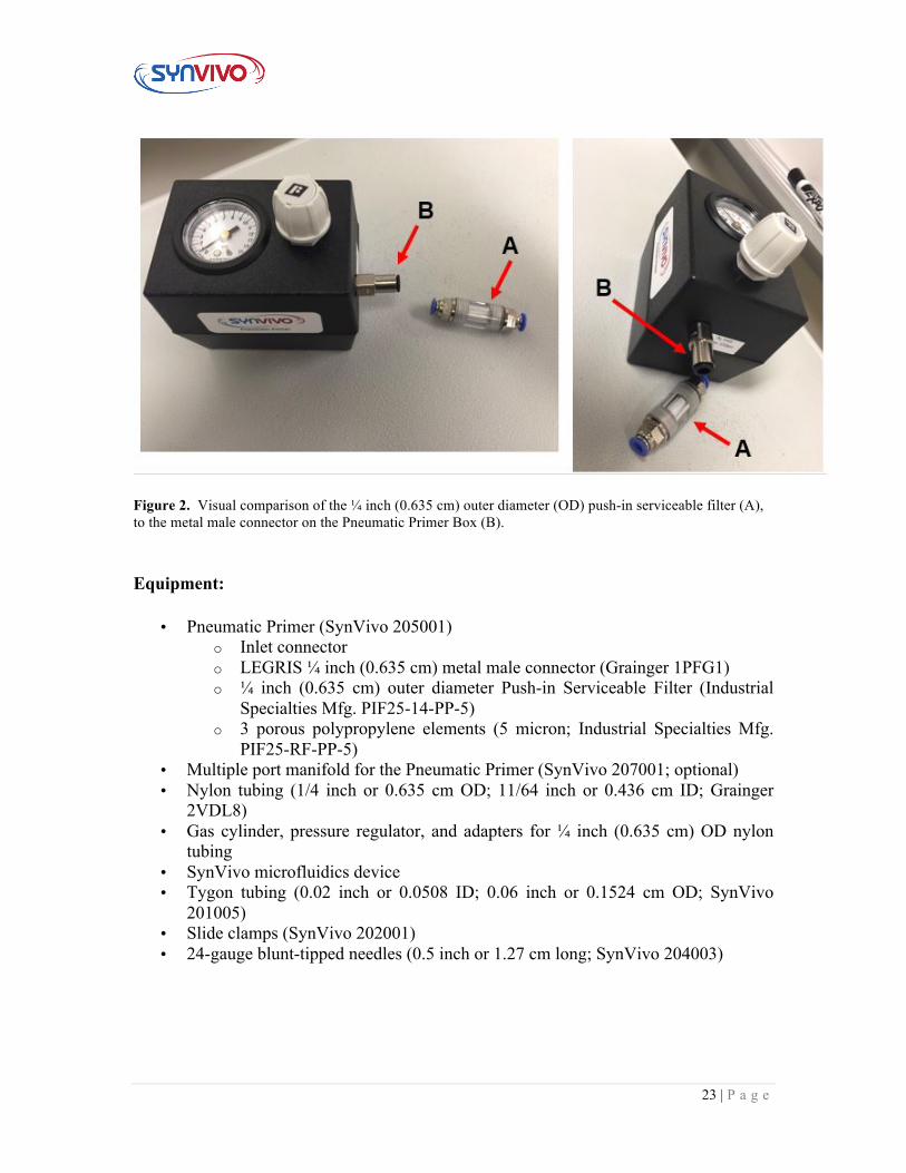
Figure 2. Visual comparison of the ¼ inch (0.635 cm) outer diameter (OD) push-in serviceable filter (A), to the metal male connector on the Pneumatic Primer Box (B).
Equipment:
• Pneumatic Primer (SynVivo 205001) o Inlet connector o LEGRIS ¼ inch (0.635 cm) metal male connector (Grainger 1PFG1) o ¼ inch (0.635 cm) outer diameter Push-in Serviceable Filter (Industrial
Specialties Mfg. PIF25-14-PP-5) o 3 porous polypropylene elements (5 micron; Industrial Specialties Mfg.
PIF25-RF-PP-5) • Multiple port manifold for the Pneumatic Primer (SynVivo 207001; optional) • Nylon tubing (1/4 inch or 0.635 cm OD; 11/64 inch or 0.436 cm ID; Grainger
2VDL8) • Gas cylinder, pressure regulator, and adapters for ¼ inch (0.635 cm) OD nylon
tubing • SynVivo microfluidics device • Tygon tubing (0.02 inch or 0.0508 ID; 0.06 inch or 0.1524 cm OD; SynVivo
201005) • Slide clamps (SynVivo 202001) • 24-gauge blunt-tipped needles (0.5 inch or 1.27 cm long; SynVivo 204003)
24 | P a g e
Protocol:
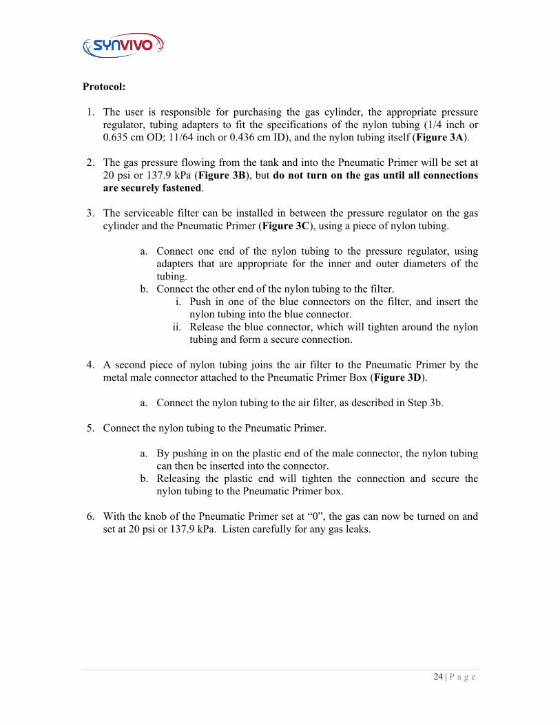
1. The user is responsible for purchasing the gas cylinder, the appropriate pressure regulator, tubing adapters to fit the specifications of the nylon tubing (1/4 inch or 0.635 cm OD; 11/64 inch or 0.436 cm ID), and the nylon tubing itself (Figure 3A).
2. The gas pressure flowing from the tank and into the Pneumatic Primer will be set at
20 psi or 137.9 kPa (Figure 3B), but do not turn on the gas until all connections are securely fastened.
3. The serviceable filter can be installed in between the pressure regulator on the gas
cylinder and the Pneumatic Primer (Figure 3C), using a piece of nylon tubing.
a. Connect one end of the nylon tubing to the pressure regulator, using adapters that are appropriate for the inner and outer diameters of the tubing.
b. Connect the other end of the nylon tubing to the filter. i. Push in one of the blue connectors on the filter, and insert the
nylon tubing into the blue connector. ii. Release the blue connector, which will tighten around the nylon
tubing and form a secure connection.
4. A second piece of nylon tubing joins the air filter to the Pneumatic Primer by the metal male connector attached to the Pneumatic Primer Box (Figure 3D).
a. Connect the nylon tubing to the air filter, as described in Step 3b.
5. Connect the nylon tubing to the Pneumatic Primer.
a. By pushing in on the plastic end of the male connector, the nylon tubing
can then be inserted into the connector. b. Releasing the plastic end will tighten the connection and secure the
nylon tubing to the Pneumatic Primer box.
6. With the knob of the Pneumatic Primer set at “0”, the gas can now be turned on and set at 20 psi or 137.9 kPa. Listen carefully for any gas leaks.
25 | P a g e
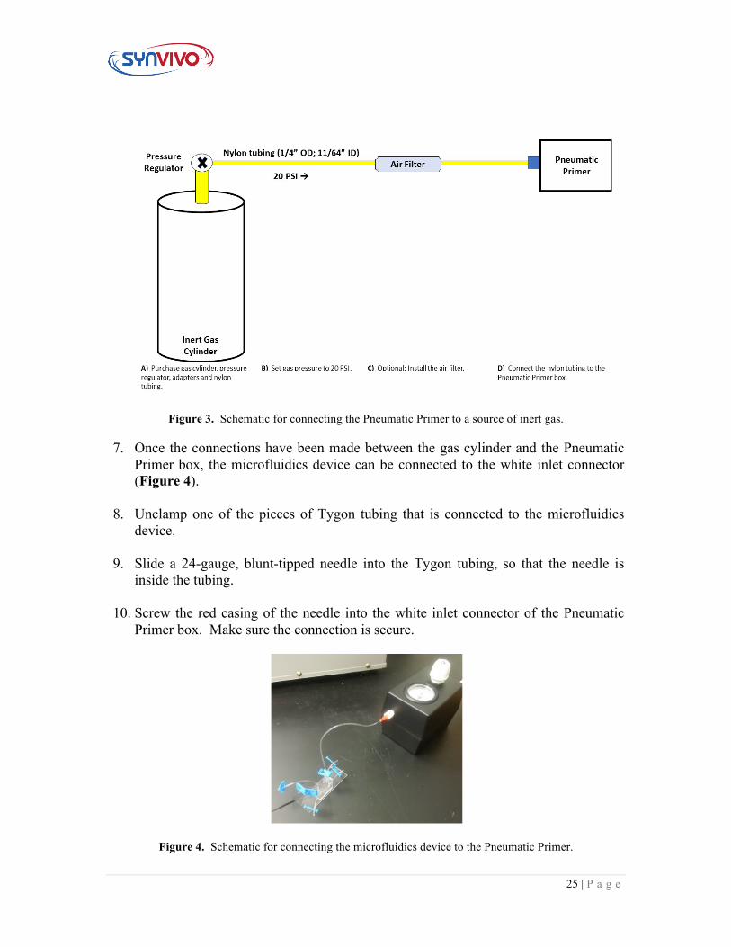
Figure 3. Schematic for connecting the Pneumatic Primer to a source of inert gas. 7. Once the connections have been made between the gas cylinder and the Pneumatic
Primer box, the microfluidics device can be connected to the white inlet connector (Figure 4).
8. Unclamp one of the pieces of Tygon tubing that is connected to the microfluidics
device. 9. Slide a 24-gauge, blunt-tipped needle into the Tygon tubing, so that the needle is
inside the tubing. 10. Screw the red casing of the needle into the white inlet connector of the Pneumatic
Primer box. Make sure the connection is secure.
Figure 4. Schematic for connecting the microfluidics device to the Pneumatic Primer.
26 | P a g e
11. Turn the white knob on the Pneumatic Primer clockwise, until gas is flowing and the
pressure on the gauge reads between 5-7 psi (34.47−48.26 kPa).
12. Listen carefully to make sure no gas is leaking out of any connections. 13. Proceed with priming as described in the SynVivo protocol.
14. Turn the white knob on the Pneumatic Primer counterclockwise to turn off the flow
of gas.
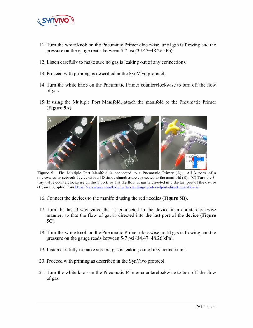
15. If using the Multiple Port Manifold, attach the manifold to the Pneumatic Primer (Figure 5A).
Figure 5. The Multiple Port Manifold is connected to a Pneumatic Primer (A). All 3 ports of a microvascular network device with a 3D tissue chamber are connected to the manifold (B). (C) Turn the 3-way valve counterclockwise on the T port, so that the flow of gas is directed into the last port of the device (D; inset graphic from https://valveman.com/blog/understanding-tport-vs-lport-directional-flows/).
16. Connect the devices to the manifold using the red needles (Figure 5B).
17. Turn the last 3-way valve that is connected to the device in a counterclockwise
manner, so that the flow of gas is directed into the last port of the device (Figure 5C).
18. Turn the white knob on the Pneumatic Primer clockwise, until gas is flowing and the
pressure on the gauge reads between 5-7 psi (34.47−48.26 kPa).
19. Listen carefully to make sure no gas is leaking out of any connections. 20. Proceed with priming as described in the SynVivo protocol.
21. Turn the white knob on the Pneumatic Primer counterclockwise to turn off the flow
of gas.
27 | P a g e
2.5 Setting up the Air Compressor
Principle:
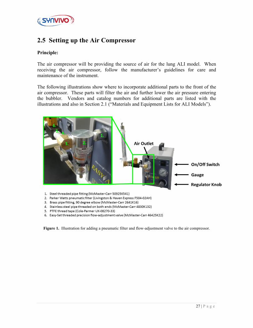
The air compressor will be providing the source of air for the lung ALI model. When receiving the air compressor, follow the manufacturer’s guidelines for care and maintenance of the instrument. The following illustrations show where to incorporate additional parts to the front of the air compressor. These parts will filter the air and further lower the air pressure entering the bubbler. Vendors and catalog numbers for additional parts are listed with the illustrations and also in Section 2.1 (“Materials and Equipment Lists for ALI Models”).
Figure 1. Illustration for adding a pneumatic filter and flow-adjustment valve to the air compressor.
28 | P a g e
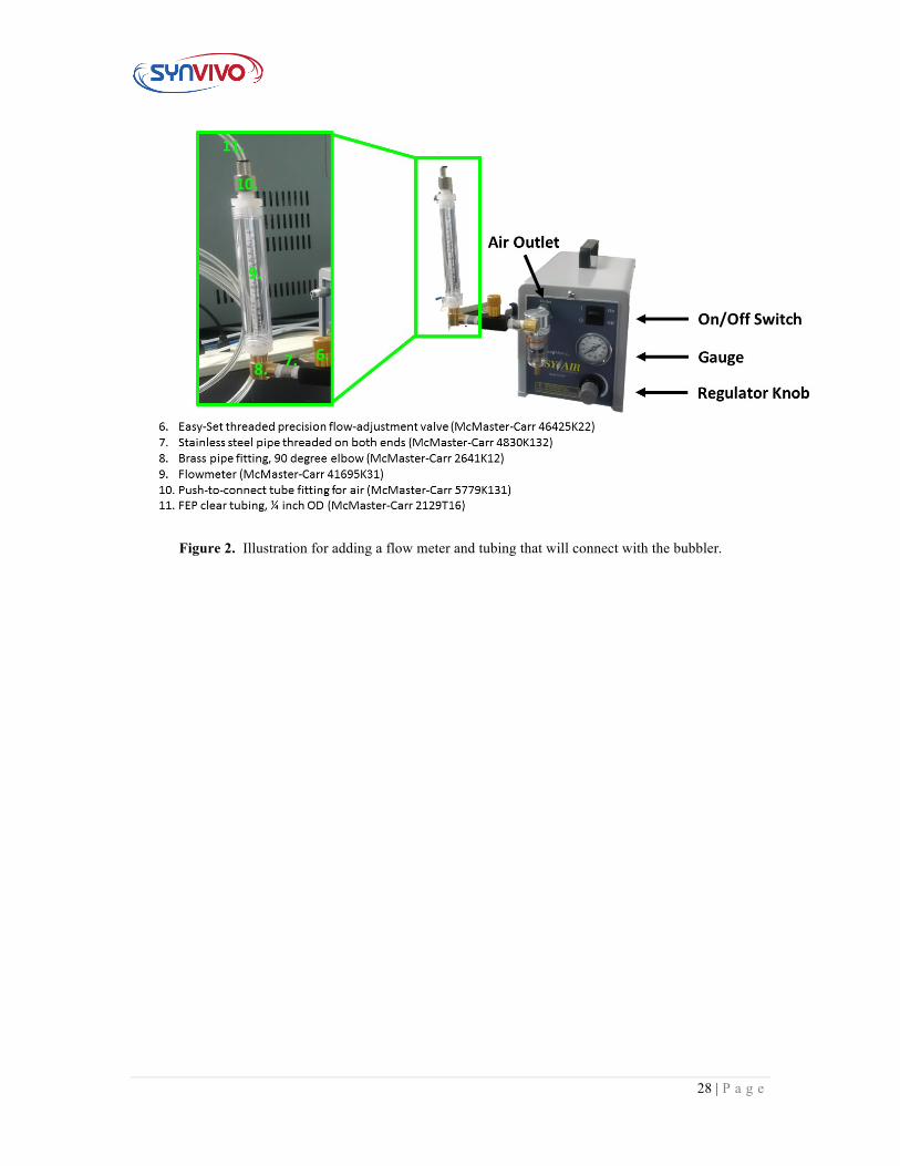
Figure 2. Illustration for adding a flow meter and tubing that will connect with the bubbler.
29 | P a g e
2.6 Connecting the Air Compressor and Microfluidic Devices to the Bubble Humidifier
Principle:
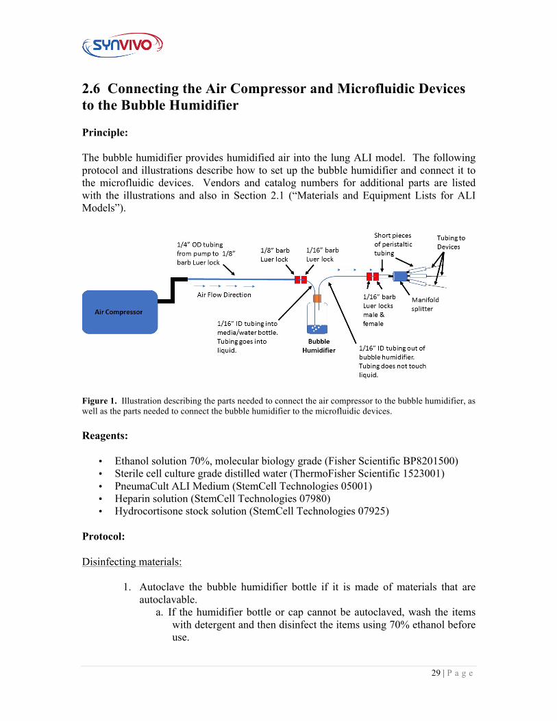
The bubble humidifier provides humidified air into the lung ALI model. The following protocol and illustrations describe how to set up the bubble humidifier and connect it to the microfluidic devices. Vendors and catalog numbers for additional parts are listed with the illustrations and also in Section 2.1 (“Materials and Equipment Lists for ALI Models”).
Figure 1. Illustration describing the parts needed to connect the air compressor to the bubble humidifier, as well as the parts needed to connect the bubble humidifier to the microfluidic devices.
Reagents:
• Ethanol solution 70%, molecular biology grade (Fisher Scientific BP8201500) • Sterile cell culture grade distilled water (ThermoFisher Scientific 1523001) • PneumaCult ALI Medium (StemCell Technologies 05001) • Heparin solution (StemCell Technologies 07980) • Hydrocortisone stock solution (StemCell Technologies 07925)
Protocol:
Disinfecting materials:
1. Autoclave the bubble humidifier bottle if it is made of materials that are autoclavable.
a. If the humidifier bottle or cap cannot be autoclaved, wash the items with detergent and then disinfect the items using 70% ethanol before use.
30 | P a g e
b. Dry bottle and cap thoroughly before using. 2. Disinfect the Luer locks by soaking in a disinfectant such as 70% ethanol for
at least 30 minutes. Dry Luer locks thoroughly before using.
3. Disinfect the manifold splitter according to the manufacturer’s instructions. a. Make sure all disinfectant has been removed from the manifold by
flowing sterile distilled water through the manifold at a continuous flow rate for at least 1 hour prior to use.
4. To disinfect the tubing, use 70% ethanol to soak the tubing. Make sure that ethanol is flowed through the tubing to completely disinfect the interior.
a. Make sure all tubing has dried completely prior to use.
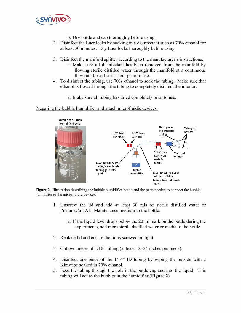
Preparing the bubble humidifier and attach microfluidic devices:
Figure 2. Illustration describing the bubble humidifier bottle and the parts needed to connect the bubble humidifier to the microfluidic devices.
1. Unscrew the lid and add at least 30 mls of sterile distilled water or PneumaCult ALI Maintenance medium to the bottle.
a. If the liquid level drops below the 20 ml mark on the bottle during the experiments, add more sterile distilled water or media to the bottle.
2. Replace lid and ensure the lid is screwed on tight.
3. Cut two pieces of 1/16” tubing (at least 12−24 inches per piece).
4. Disinfect one piece of the 1/16” ID tubing by wiping the outside with a
Kimwipe soaked in 70% ethanol. 5. Feed the tubing through the hole in the bottle cap and into the liquid. This
tubing will act as the bubbler in the humidifier (Figure 2).
31 | P a g e
6. Connect the opposite end of the tubing to the 1/16” barb Luer lock.
7. Disinfect a second piece of the 1/16” ID tubing by wiping the outside with a Kimwipe soaked in 70% ethanol.
8. Feed the tubing through the hole in the bottle cap and into the bottle but not
into the liquid (Figure 2). This tubing will act as the conduit for transferring humidified air into the microfluidic devices.
9. Connect the opposite end of the tubing to two 1/16” barb Luer locks joined
together.
10. Connect the manifold splitter to the end of one of the 1/16” barb Luer locks using a short piece of peristaltic tubing (Figure 2).
11. Place short pieces of peristaltic tubing on the manifold splitter.
12. Slide inlet tubing from the center channels of the microfluidic devices into
the peristaltic tubing on the manifold splitter. The microfluidic devices are now joined to the bubble humidifier.
13. Wipe off the bubble humidifier with a Kimwipe soaked in 70% ethanol.
14. Place the bubble humidifier in the tissue culture incubator.
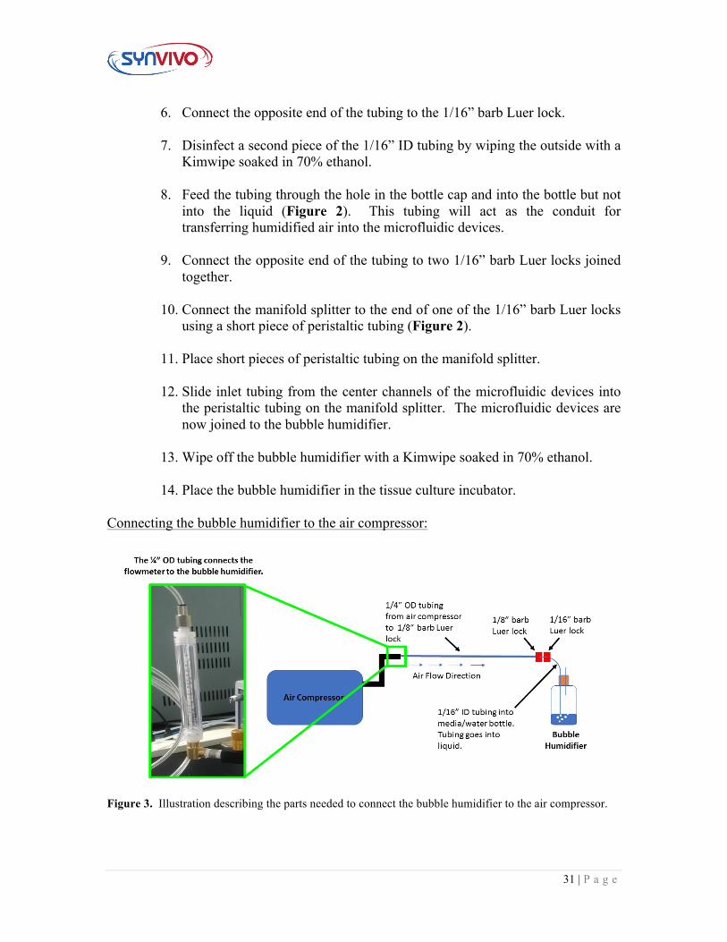
Connecting the bubble humidifier to the air compressor:
Figure 3. Illustration describing the parts needed to connect the bubble humidifier to the air compressor.
32 | P a g e
1. The flowmeter attached the air compressor is connected to ¼” OD tubing (Figure 3).
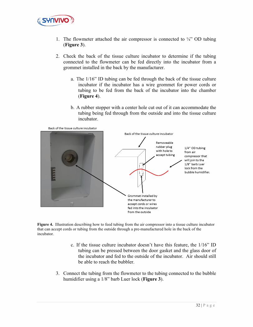
2. Check the back of the tissue culture incubator to determine if the tubing
connected to the flowmeter can be fed directly into the incubator from a grommet installed in the back by the manufacturer.
a. The 1/16” ID tubing can be fed through the back of the tissue culture
incubator if the incubator has a wire grommet for power cords or tubing to be fed from the back of the incubator into the chamber (Figure 4).
b. A rubber stopper with a center hole cut out of it can accommodate the tubing being fed through from the outside and into the tissue culture incubator.
Figure 4. Illustration describing how to feed tubing from the air compressor into a tissue culture incubator that can accept cords or tubing from the outside through a pre-manufactured hole in the back of the incubator.
c. If the tissue culture incubator doesn’t have this feature, the 1/16” ID
tubing can be pressed between the door gasket and the glass door of the incubator and fed to the outside of the incubator. Air should still be able to reach the bubbler.
3. Connect the tubing from the flowmeter to the tubing connected to the bubble humidifier using a 1/8” barb Luer lock (Figure 3).
33 | P a g e
a. An additional ¼ inch (0.635 cm) outer diameter push-in serviceable in-line filter can be added in between the flowmeter and the bubble humidifier if additional air filtration is needed for sterility.
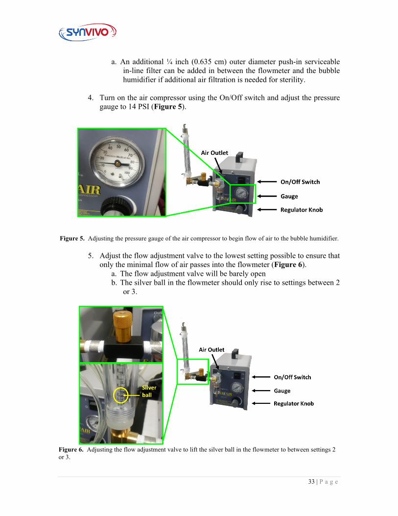
4. Turn on the air compressor using the On/Off switch and adjust the pressure
gauge to 14 PSI (Figure 5).
Figure 5. Adjusting the pressure gauge of the air compressor to begin flow of air to the bubble humidifier.
5. Adjust the flow adjustment valve to the lowest setting possible to ensure that only the minimal flow of air passes into the flowmeter (Figure 6).
a. The flow adjustment valve will be barely open b. The silver ball in the flowmeter should only rise to settings between 2
or 3.
Figure 6. Adjusting the flow adjustment valve to lift the silver ball in the flowmeter to between settings 2 or 3.
34 | P a g e
6. Check the bubble humidifier for continuous bubbling. Adjust the flow adjustment valve as necessary until continuous bubbling is achieved in the humidifier.
7. The system is now ready to use.
35 | P a g e
Section 3:
Preparing the Microfluidic Device
36 | P a g e
3.1 Rinsing and Priming Devices Principle:
Bubble-free filling of complex microvascular networks with aqueous media can be challenging when using a microfluidic device. Even with a hydrophilic surface, air can be easily trapped inside the channels when the device is first filled with liquid.
One method for removing air from microfluidic devices involves purging the system with an inert gas (usually nitrogen or argon) for a specific length of time (usually 30 minutes to 1 hour). The gas is under pressure (between 5-7 psi or 34-48 kPa), allowing the trapped air to escape through the pores in the PDMS. This method requires a source of inert gas, as well as a pressure regulator to control the flow of gas into the device.
Equipment:
• SynVivo microfluidics device • Tygon tubing (0.02 inch ID x 0.06 inch OD, or 0.05 cm ID x 0.15 cm OD;
SynVivo 201005) • Blue slide clamps (SynVivo 202001) • 1 mL syringe with Luer-Lok tip (25 pack; SynVivo 203005) • 24-gauge blunt-tipped needles (0.5 inches or 1.27 cm long; SynVivo 204003) • Pneumatic Primer (SynVivo 205001) • Forceps (ultra-fine; VWR 100494-698) • Stainless steel scissors (Fisher Scientific 19-062530) • Multiple port manifold for the Pneumatic Primer (SynVivo 207001) • Source of inert compressed gas
Reagents:
• 1X PBS without calcium or magnesium (Corning 21040CV) • Sterile cell culture grade distilled water (ThermoFisher Scientific 1523001)
Protocol: The following protocol should be carried out within a laminar flow hood as much as possible to maintain sterility.
37 | P a g e
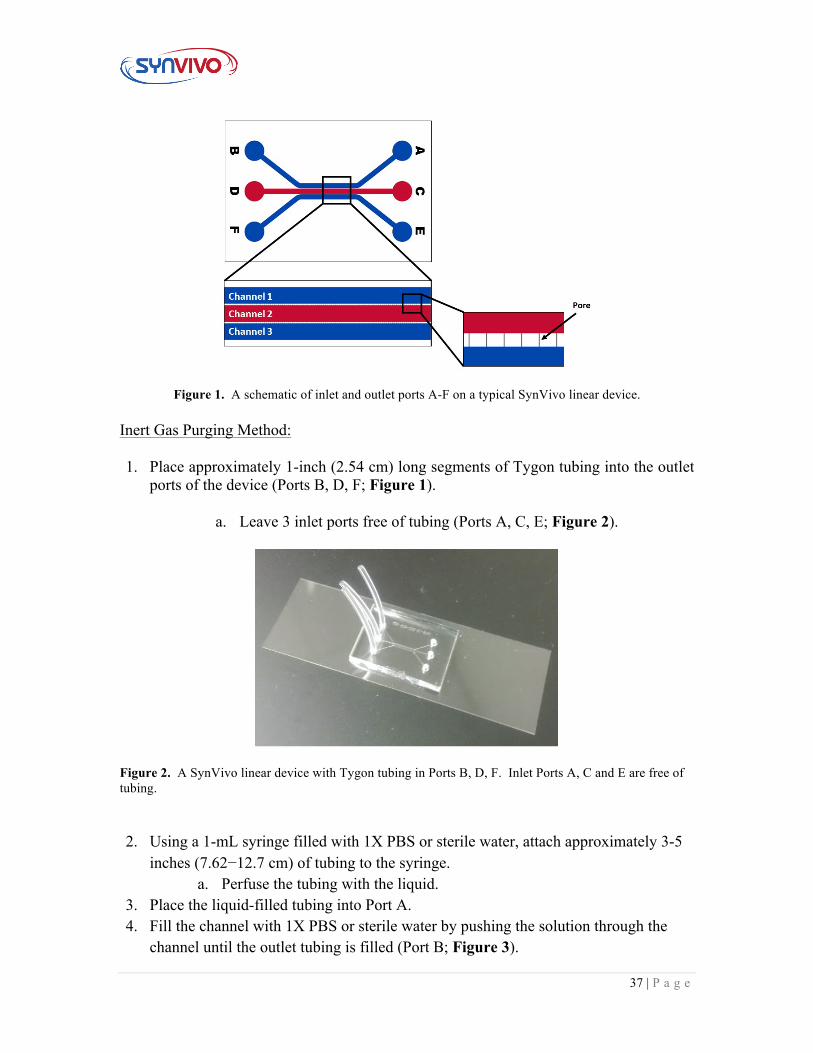
Figure 1. A schematic of inlet and outlet ports A-F on a typical SynVivo linear device. Inert Gas Purging Method: 1. Place approximately 1-inch (2.54 cm) long segments of Tygon tubing into the outlet
ports of the device (Ports B, D, F; Figure 1).
a. Leave 3 inlet ports free of tubing (Ports A, C, E; Figure 2).
Figure 2. A SynVivo linear device with Tygon tubing in Ports B, D, F. Inlet Ports A, C and E are free of tubing. 2. Using a 1-mL syringe filled with 1X PBS or sterile water, attach approximately 3-5
inches (7.62−12.7 cm) of tubing to the syringe. a. Perfuse the tubing with the liquid.
3. Place the liquid-filled tubing into Port A. 4. Fill the channel with 1X PBS or sterile water by pushing the solution through the
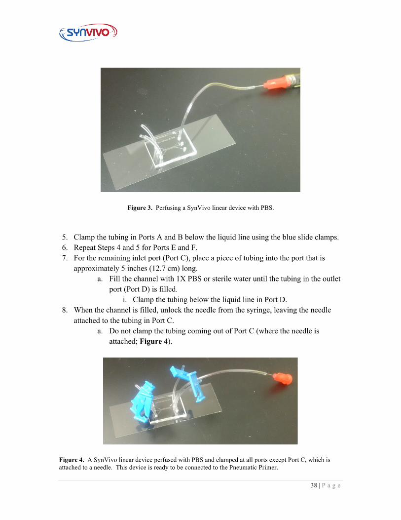
channel until the outlet tubing is filled (Port B; Figure 3).
38 | P a g e
Figure 3. Perfusing a SynVivo linear device with PBS. 5. Clamp the tubing in Ports A and B below the liquid line using the blue slide clamps. 6. Repeat Steps 4 and 5 for Ports E and F. 7. For the remaining inlet port (Port C), place a piece of tubing into the port that is
approximately 5 inches (12.7 cm) long. a. Fill the channel with 1X PBS or sterile water until the tubing in the outlet
port (Port D) is filled. i. Clamp the tubing below the liquid line in Port D.
8. When the channel is filled, unlock the needle from the syringe, leaving the needle attached to the tubing in Port C.
a. Do not clamp the tubing coming out of Port C (where the needle is attached; Figure 4).
Figure 4. A SynVivo linear device perfused with PBS and clamped at all ports except Port C, which is attached to a needle. This device is ready to be connected to the Pneumatic Primer.
39 | P a g e
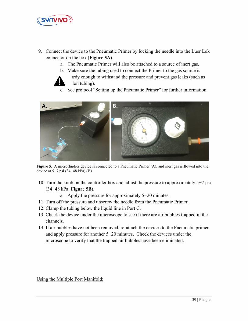
9. Connect the device to the Pneumatic Primer by locking the needle into the Luer Lok
connector on the box (Figure 5A). a. The Pneumatic Primer will also be attached to a source of inert gas. b. Make sure the tubing used to connect the Primer to the gas source is
sturdy enough to withstand the pressure and prevent gas leaks (such as nylon tubing).
c. See protocol “Setting up the Pneumatic Primer” for further information.
Figure 5. A microfluidics device is connected to a Pneumatic Primer (A), and inert gas is flowed into the device at 5−7 psi (34−48 kPa) (B). 10. Turn the knob on the controller box and adjust the pressure to approximately 5−7 psi
(34−48 kPa; Figure 5B). a. Apply the pressure for approximately 5−20 minutes.
11. Turn off the pressure and unscrew the needle from the Pneumatic Primer. 12. Clamp the tubing below the liquid line in Port C. 13. Check the device under the microscope to see if there are air bubbles trapped in the
channels. 14. If air bubbles have not been removed, re-attach the devices to the Pneumatic primer
and apply pressure for another 5−20 minutes. Check the devices under the microscope to verify that the trapped air bubbles have been eliminated.
Using the Multiple Port Manifold:
40 | P a g e
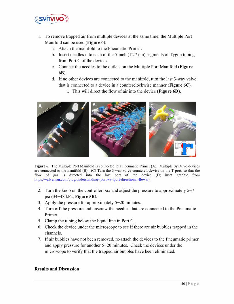
1. To remove trapped air from multiple devices at the same time, the Multiple Port Manifold can be used (Figure 6).
a. Attach the manifold to the Pneumatic Primer. b. Insert needles into each of the 5-inch (12.7 cm) segments of Tygon tubing
from Port C of the devices. c. Connect the needles to the outlets on the Multiple Port Manifold (Figure
6B). d. If no other devices are connected to the manifold, turn the last 3-way valve
that is connected to a device in a counterclockwise manner (Figure 6C). i. This will direct the flow of air into the device (Figure 6D).
Figure 6. The Multiple Port Manifold is connected to a Pneumatic Primer (A). Multiple SynVivo devices are connected to the manifold (B). (C) Turn the 3-way valve counterclockwise on the T port, so that the flow of gas is directed into the last port of the device (D; inset graphic from https://valveman.com/blog/understanding-tport-vs-lport-directional-flows/).
2. Turn the knob on the controller box and adjust the pressure to approximately 5−7 psi (34−48 kPa; Figure 5B).
3. Apply the pressure for approximately 5−20 minutes. 4. Turn off the pressure and unscrew the needles that are connected to the Pneumatic
Primer. 5. Clamp the tubing below the liquid line in Port C. 6. Check the device under the microscope to see if there are air bubbles trapped in the
channels. 7. If air bubbles have not been removed, re-attach the devices to the Pneumatic primer
and apply pressure for another 5−20 minutes. Check the devices under the microscope to verify that the trapped air bubbles have been eliminated.
Results and Discussion
41 | P a g e
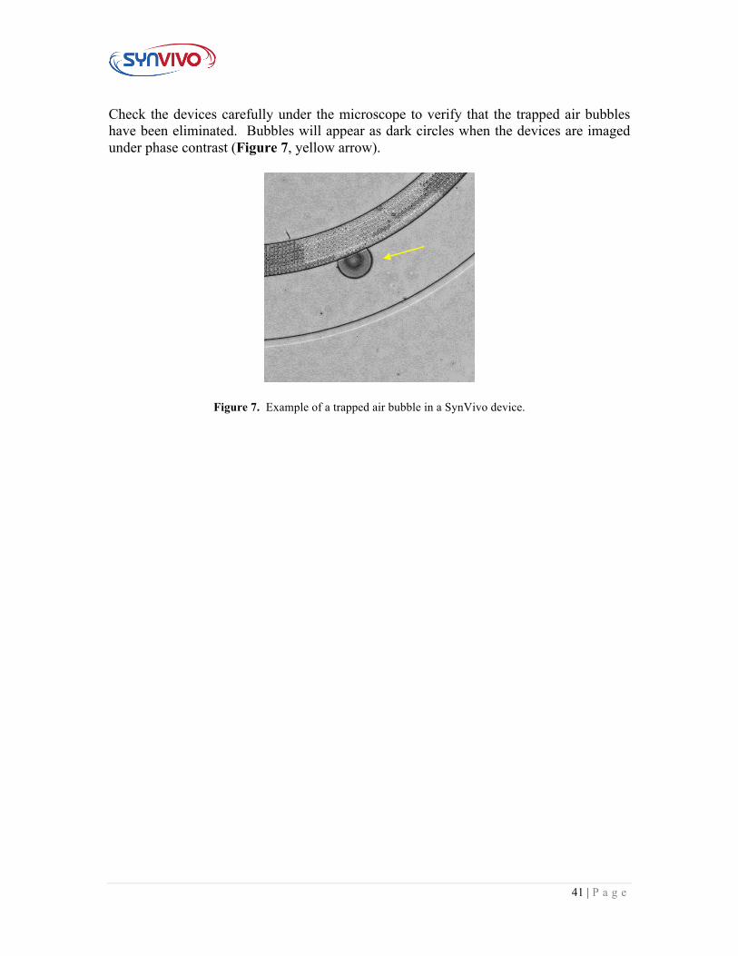
Check the devices carefully under the microscope to verify that the trapped air bubbles have been eliminated. Bubbles will appear as dark circles when the devices are imaged under phase contrast (Figure 7, yellow arrow).
Figure 7. Example of a trapped air bubble in a SynVivo device.
42 | P a g e
3.2 Establishing the Basement Membrane Principle:
The extracellular matrix (ECM), or basement membrane, is a structural framework of proteins that provides a scaffold for cells comprising a tissue. The following protocols will describe how to create a thin or thick ECM coating in the channels of a SynVivo linear device.
Equipment:
• SynVivo microfluidics device • Tygon tubing (0.02 inch ID x 0.06 inch OD, or 0.05 cm ID x 0.15 cm OD;
SynVivo 201005) • Slide clamps (SynVivo 202001) • 1 mL syringe with Luer-Lok tip (25 pack; SynVivo 203005) • 24-gauge blunt-tipped needles (0.5 inches or 1.27 cm long; SynVivo 204003) • Ice bucket with ice • Tissue culture incubator • Refrigerator • Kimwipes (Fisher Scientific 06-666) • Parafilm Laboratory Wrapping Film (Fisher Scientific 13-374-12) • Disposable Petri dish (Corning 351058) • Forceps (ultra-fine; VWR 100494-698) • Stainless steel scissors (Fisher Scientific 19-062530)
Reagents:
• 1X PBS without calcium or magnesium (Corning 21040CV) • 10X PBS without calcium or magnesium (Corning 46013CM) • Sterile cell culture grade distilled water (ThermoFisher Scientific 1523001) • Serum-free tissue culture media (DMEM, RPMI, or basal medium without serum) • 1.0N NaOH (Sigma Aldrich S2770-100ML) • Collagen, type IV, human placental (Sigma Aldrich C5533-5MG)
o Dilute in glacial acetic acid to create a stock concentration of 1000 µg/mL (store at 4°C)
43 | P a g e
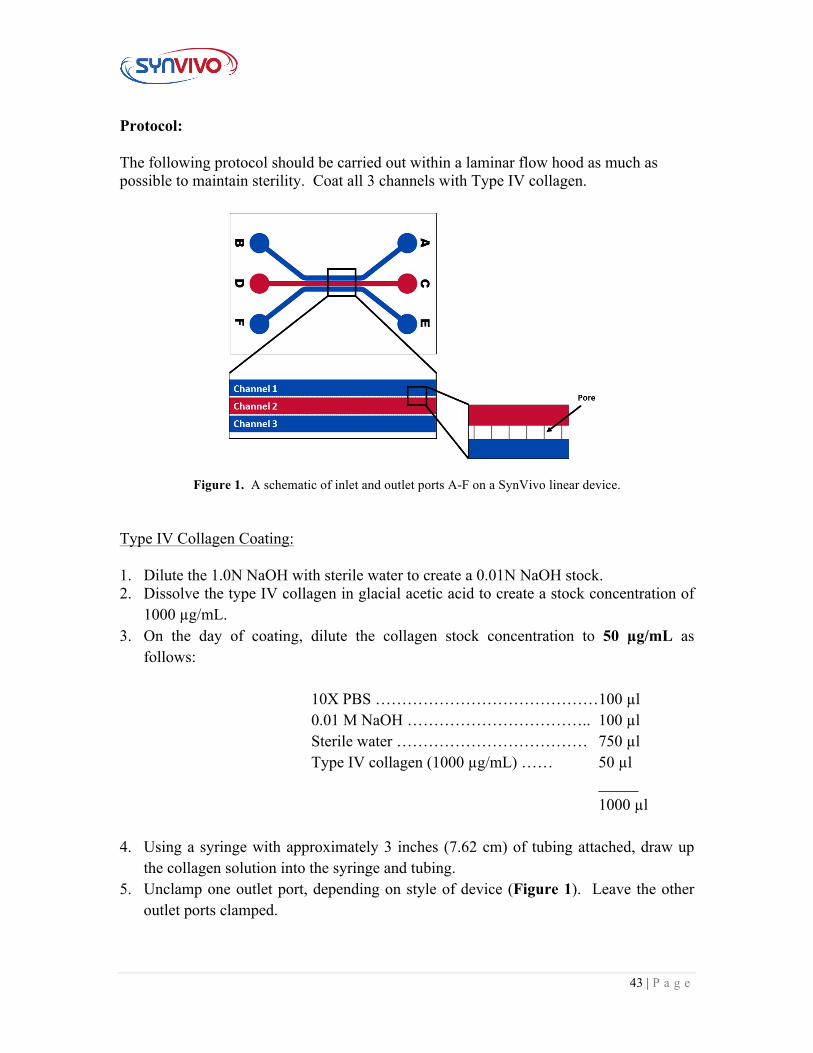
Protocol: The following protocol should be carried out within a laminar flow hood as much as possible to maintain sterility. Coat all 3 channels with Type IV collagen.
Figure 1. A schematic of inlet and outlet ports A-F on a SynVivo linear device. Type IV Collagen Coating: 1. Dilute the 1.0N NaOH with sterile water to create a 0.01N NaOH stock. 2. Dissolve the type IV collagen in glacial acetic acid to create a stock concentration of
1000 µg/mL. 3. On the day of coating, dilute the collagen stock concentration to 50 µg/mL as
follows:
10X PBS ……………………………………100 µl 0.01 M NaOH …………………………….. 100 µl Sterile water ……………………………… 750 µl Type IV collagen (1000 µg/mL) …… 50 µl
_____ 1000 µl
4. Using a syringe with approximately 3 inches (7.62 cm) of tubing attached, draw up the collagen solution into the syringe and tubing.
5. Unclamp one outlet port, depending on style of device (Figure 1). Leave the other outlet ports clamped.
44 | P a g e
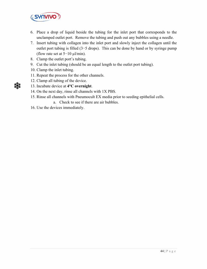
6. Place a drop of liquid beside the tubing for the inlet port that corresponds to the unclamped outlet port. Remove the tubing and push out any bubbles using a needle.
7. Insert tubing with collagen into the inlet port and slowly inject the collagen until the outlet port tubing is filled (3−5 drops). This can be done by hand or by syringe pump (flow rate set at 5−10 µl/min).
8. Clamp the outlet port’s tubing. 9. Cut the inlet tubing (should be an equal length to the outlet port tubing). 10. Clamp the inlet tubing. 11. Repeat the process for the other channels. 12. Clamp all tubing of the device. 13. Incubate device at 4°C overnight. 14. On the next day, rinse all channels with 1X PBS. 15. Rinse all channels with Pneumocult EX media prior to seeding epithelial cells.
a. Check to see if there are air bubbles. 16. Use the devices immediately.

45 | P a g e
Section 4:
Establishing the Lung ALI Model
46 | P a g e
4.1 Lung ALI Model Timeline and Milestones Principle:
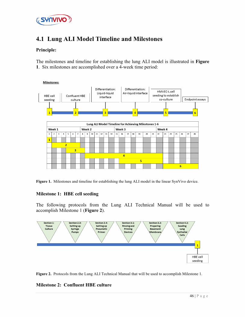
The milestones and timeline for establishing the lung ALI model is illustrated in Figure 1. Six milestones are accomplished over a 4-week time period:
Figure 1. Milestones and timeline for establishing the lung ALI model in the linear SynVivo device.
Milestone 1: HBE cell seeding The following protocols from the Lung ALI Technical Manual will be used to accomplish Milestone 1 (Figure 2).
Figure 2. Protocols from the Lung ALI Technical Manual that will be used to accomplish Milestone 1.
Milestone 2: Confluent HBE culture
47 | P a g e
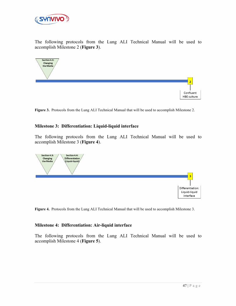
The following protocols from the Lung ALI Technical Manual will be used to accomplish Milestone 2 (Figure 3).
Figure 3. Protocols from the Lung ALI Technical Manual that will be used to accomplish Milestone 2.
Milestone 3: Differentiation: Liquid-liquid interface The following protocols from the Lung ALI Technical Manual will be used to accomplish Milestone 3 (Figure 4).
Figure 4. Protocols from the Lung ALI Technical Manual that will be used to accomplish Milestone 3.
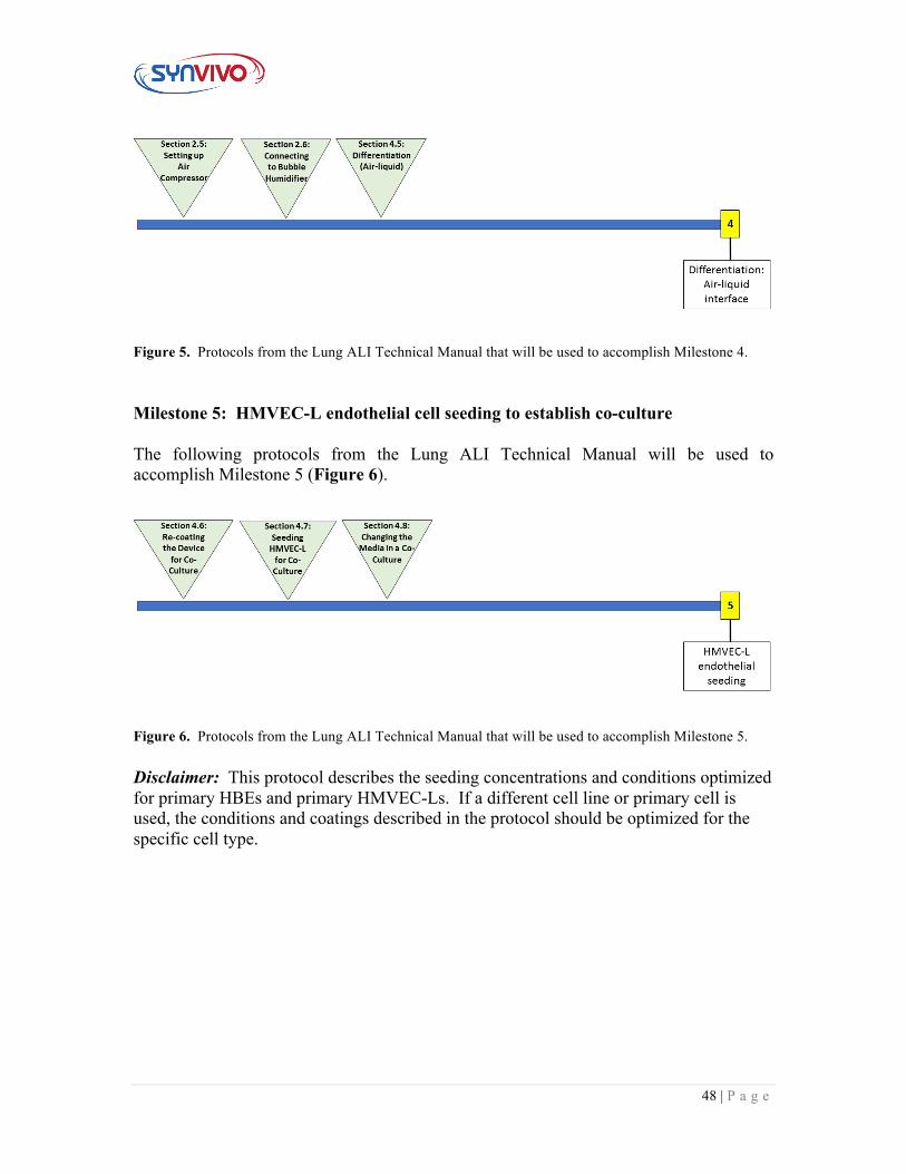
Milestone 4: Differentiation: Air-liquid interface The following protocols from the Lung ALI Technical Manual will be used to accomplish Milestone 4 (Figure 5).
48 | P a g e
Figure 5. Protocols from the Lung ALI Technical Manual that will be used to accomplish Milestone 4.
Milestone 5: HMVEC-L endothelial cell seeding to establish co-culture The following protocols from the Lung ALI Technical Manual will be used to accomplish Milestone 5 (Figure 6).
Figure 6. Protocols from the Lung ALI Technical Manual that will be used to accomplish Milestone 5.
Disclaimer: This protocol describes the seeding concentrations and conditions optimized for primary HBEs and primary HMVEC-Ls. If a different cell line or primary cell is used, the conditions and coatings described in the protocol should be optimized for the specific cell type.
49 | P a g e
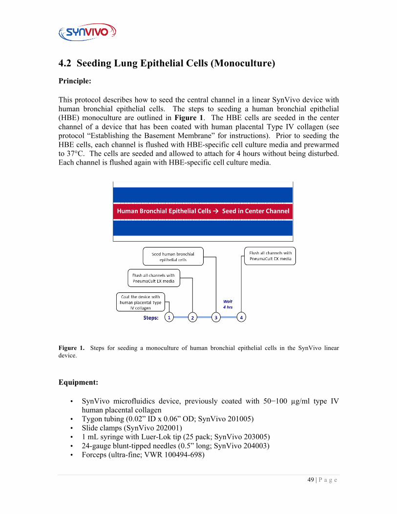
4.2 Seeding Lung Epithelial Cells (Monoculture) Principle:
This protocol describes how to seed the central channel in a linear SynVivo device with human bronchial epithelial cells. The steps to seeding a human bronchial epithelial (HBE) monoculture are outlined in Figure 1. The HBE cells are seeded in the center channel of a device that has been coated with human placental Type IV collagen (see protocol “Establishing the Basement Membrane” for instructions). Prior to seeding the HBE cells, each channel is flushed with HBE-specific cell culture media and prewarmed to 37°C. The cells are seeded and allowed to attach for 4 hours without being disturbed. Each channel is flushed again with HBE-specific cell culture media.
Figure 1. Steps for seeding a monoculture of human bronchial epithelial cells in the SynVivo linear device.
Equipment:
• SynVivo microfluidics device, previously coated with 50−100 µg/ml type IV human placental collagen
• Tygon tubing (0.02” ID x 0.06” OD; SynVivo 201005) • Slide clamps (SynVivo 202001) • 1 mL syringe with Luer-Lok tip (25 pack; SynVivo 203005) • 24-gauge blunt-tipped needles (0.5” long; SynVivo 204003) • Forceps (ultra-fine; VWR 100494-698)
50 | P a g e
• Stainless steel scissors (Fisher Scientific 19-062530) • T75 flasks (Corning 430641) • Syringe pump (Harvard Apparatus) • Tissue culture incubator
Primary Cells:
• Human Bronchial Epithelial Cells (HBEs)
Reagents:
• 1X PBS without calcium or magnesium (Corning 21040CV) • 10X PBS • 0.01M NaOH • Sterile water • Human placental collagen Type IV, reconstituted in 0.02M acetic acid (Sigma,
C5533) • PneumaCult EX Culture Medium (StemCell Technologies 05008) • 1X TrpLE Express cell detachment solution, no phenol red (ThermoFisher
Scientific 12604013) o Can be substituted with Trypsin-EDTA for Primary Cells (ATCC PCS-
999-003); follow the manufacturer’s guidelines • HEPES buffered saline (Lonza CC-5022)
Protocol: Prewarm the microfluidic device:
1. Place the microfluidic device at 37°C to prewarm while preparing the cells. Dissociating epithelial cells from the flask:
2. Flush all channels of the pre-coated SynVivo device with complete epithelial cell media.
a. This step will ensure that the entire device is primed with epithelial cell media prior to seeding.
3. Remove and discard the epithelial cell media from the T25 flask of epithelial cells.
4. Rinse the epithelial cells twice with room temperature HEPES buffered saline. a. Gently rock the flask in between rinses. b. Remove final rinse and discard.
5. Add 3 mL of room 0.05% Trypsin-EDTA to the flask. 6. Incubate flask at 37°C for 5−7 minutes.
51 | P a g e
7. Add 3 mL of defined trypsin inhibitor to the flask to neutralize the dissociation reagent.
8. Gently wash the sides of the flask to remove the adherent cells. 9. Pellet the cells by centrifugation.
a. Use 200 x g (1000 RPM) for 5−10 minutes at room temperature (do not use speeds greater than 1000 RPM).
10. Remove the media, leaving behind at least 100 µl to cover the cell pellet. 11. Wash the cells twice with 5 mL complete epithelial cell media, and pellet the
cells by centrifugation. a. Use 200 x g for 5 minutes at room temperature (do not use speeds greater
than 1000 RPM).
Cell counting:
1. Resuspend the cells in an appropriate volume of growth medium to allow for counting
2. Count the cells using a hemacytometer 3. Calculate the volume of cell suspension needed to obtain a cell concentration of
approximately 1−5 x 10⁷ cells/ml in Pneumacult EX culture media.
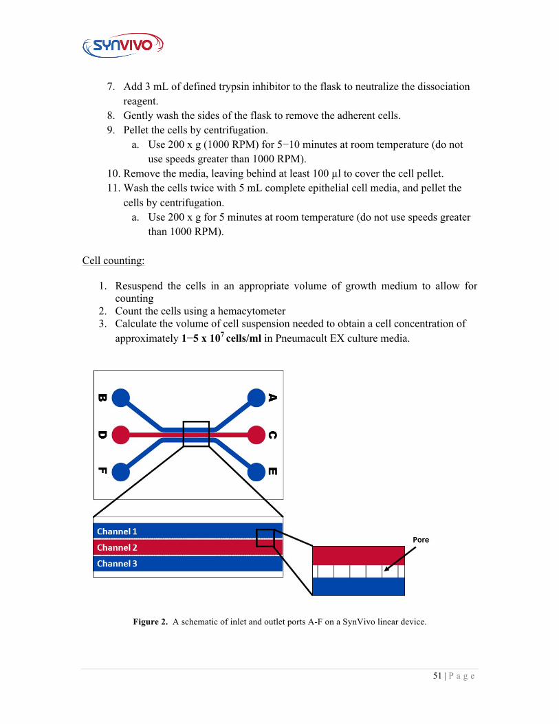
Figure 2. A schematic of inlet and outlet ports A-F on a SynVivo linear device.
52 | P a g e
Seeding epithelial cells into the SynVivo devices:
1. Unclamp one outlet port of the center channel (the red Channel 2 shown in Figure 2). Leave the other channels clamped.
2. Place a drop of liquid beside the tubing for the inlet port. Remove the tubing and push out any bubbles using a needle.
3. Draw back the plunger of a 1-mL syringe to the 0.3 mL mark. 4. If seeding by hand:
a. Load the Tygon tubing with the previously prepared cell suspension. Draw up enough cells to fill the tubing, but do not bring the cells into the syringe barrel.
b. Make sure that the tubing is free of air bubbles. c. Push the cell mixture out until it is flush with the end of
the tubing. 5. If seeding by a syringe pump:
a. Mount the syringe onto a syringe pump. b. Load the Tygon tubing with the previously prepared cell
suspension, using the withdraw button on the syringe pump (double arrows pointing to the left).
i. Draw up enough cells to fill the tubing, but do not bring the cells into the syringe barrel.
c. Make sure that the tubing is free of air bubbles. d. Using the rapid infuse button on the syringe pump (double
arrows pointing to the right), make sure the cell mixture is flush with the end of the tubing.
6. Insert the tubing into the inlet port - the drop of water will prevent air entering the device as the tubing is inserted.
7. Clean the fluid from the surface of the device. 8. Inject the cells into the device:
a. If using a syringe pump, begin the injection at a flow rate of 1−5 µl/min.
b. If seeding by hand, gently push the plunger forward. Watch the fluid line inside the Tygon tubing carefully.
9. Watch the device as the cells are flowing. Once the center channel is filled with cells, stop the flow and clamp the outlet tubing.
a. Wiggle the clamped outlet tubing to distribute the cells evenly through the channel.
b. Only do this while the syringe is still connected to the inlet port.
53 | P a g e
10. Carefully and quickly cut the inlet tubing, keeping the length of the inlet tubing as small as possible.
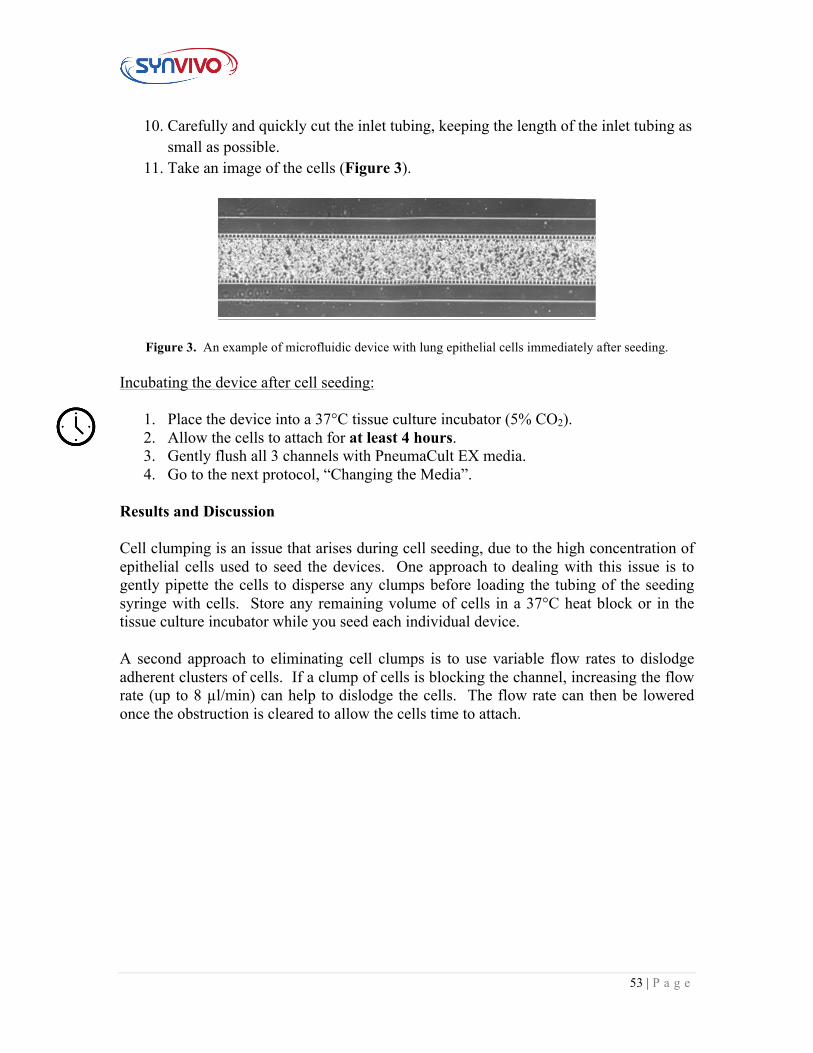
11. Take an image of the cells (Figure 3).
Figure 3. An example of microfluidic device with lung epithelial cells immediately after seeding. Incubating the device after cell seeding:
1. Place the device into a 37°C tissue culture incubator (5% CO2). 2. Allow the cells to attach for at least 4 hours. 3. Gently flush all 3 channels with PneumaCult EX media. 4. Go to the next protocol, “Changing the Media”.
Results and Discussion
Cell clumping is an issue that arises during cell seeding, due to the high concentration of epithelial cells used to seed the devices. One approach to dealing with this issue is to gently pipette the cells to disperse any clumps before loading the tubing of the seeding syringe with cells. Store any remaining volume of cells in a 37°C heat block or in the tissue culture incubator while you seed each individual device.
A second approach to eliminating cell clumps is to use variable flow rates to dislodge adherent clusters of cells. If a clump of cells is blocking the channel, increasing the flow rate (up to 8 µl/min) can help to dislodge the cells. The flow rate can then be lowered once the obstruction is cleared to allow the cells time to attach.
54 | P a g e
4.3 Changing the Media in a Lung Epithelial Monoculture
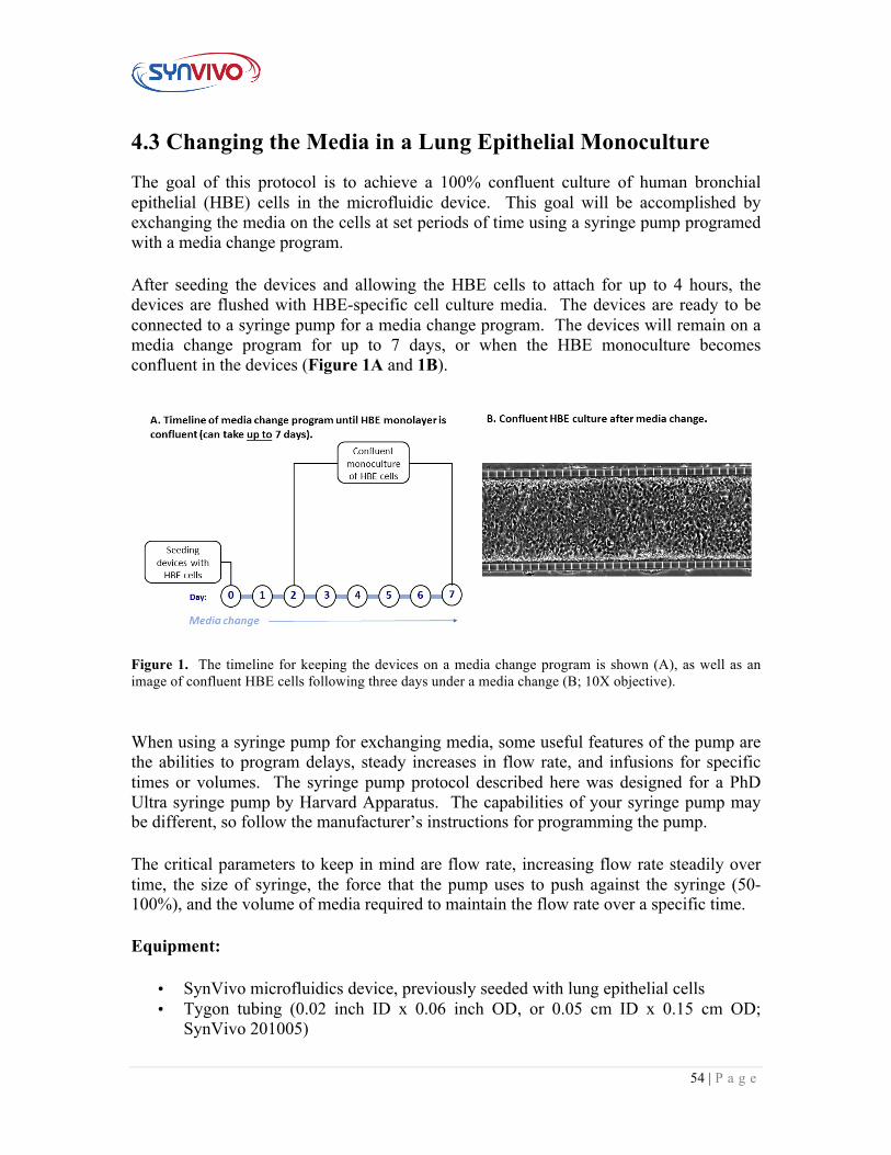
The goal of this protocol is to achieve a 100% confluent culture of human bronchial epithelial (HBE) cells in the microfluidic device. This goal will be accomplished by exchanging the media on the cells at set periods of time using a syringe pump programed with a media change program.
After seeding the devices and allowing the HBE cells to attach for up to 4 hours, the devices are flushed with HBE-specific cell culture media. The devices are ready to be connected to a syringe pump for a media change program. The devices will remain on a media change program for up to 7 days, or when the HBE monoculture becomes confluent in the devices (Figure 1A and 1B).
Figure 1. The timeline for keeping the devices on a media change program is shown (A), as well as an image of confluent HBE cells following three days under a media change (B; 10X objective).
When using a syringe pump for exchanging media, some useful features of the pump are the abilities to program delays, steady increases in flow rate, and infusions for specific times or volumes. The syringe pump protocol described here was designed for a PhD Ultra syringe pump by Harvard Apparatus. The capabilities of your syringe pump may be different, so follow the manufacturer’s instructions for programming the pump.
The critical parameters to keep in mind are flow rate, increasing flow rate steadily over time, the size of syringe, the force that the pump uses to push against the syringe (50-100%), and the volume of media required to maintain the flow rate over a specific time.
Equipment:
• SynVivo microfluidics device, previously seeded with lung epithelial cells • Tygon tubing (0.02 inch ID x 0.06 inch OD, or 0.05 cm ID x 0.15 cm OD;
SynVivo 201005)
55 | P a g e
• Slide clamps (SynVivo 202001) • 1 mL syringe with Luer-Lok tip (25 pack; SynVivo 203005) • 24-gauge blunt-tipped needles (0.5 inches or 1.27 cm long; SynVivo 204003) • Forceps (ultra-fine; VWR 100494-698) • Stainless steel scissors (Fisher Scientific 19-062530) • Syringe pump (PhD Ultra; Harvard Apparatus; SynVivo 301001 or 301002) • Tissue culture incubator • Sterile large Petri dishes (150 x 15mm; VWR 25384-326)
Reagents:
• 1X PBS without calcium or magnesium (Corning 21040CV) • PneumaCult EX Culture Medium (StemCell Technologies 05008)
Protocol:
Program the pump with the media exchange program:
1. Name the new method “Media Change_HBE”.
2. Under the “Syringe Select” screen, set the diameter to 4.699 mm (SynVivo
203005; 1 mL syringes) by pressing the “Diameter” key and using the arrow keys
to scroll through the numbers.
a. If a different 1 mL syringe is to be used, see the manufacturer’s
information for more details regarding diameter information.
3. Choose the Step Definition button.
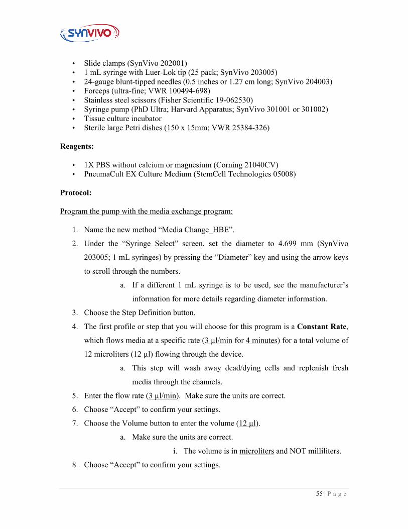
4. The first profile or step that you will choose for this program is a Constant Rate,
which flows media at a specific rate (3 µl/min for 4 minutes) for a total volume of
12 microliters (12 µl) flowing through the device.
a. This step will wash away dead/dying cells and replenish fresh
media through the channels.
5. Enter the flow rate (3 µl/min). Make sure the units are correct.
6. Choose “Accept” to confirm your settings.
7. Choose the Volume button to enter the volume (12 µl).
a. Make sure the units are correct.
i. The volume is in microliters and NOT milliliters.
8. Choose “Accept” to confirm your settings.
56 | P a g e
9. Choose “Accept” again to return to the Step Definition screen.
10. From the Step Definition menu, the second profile or step that you will choose for
this program is a Delay, where no fluid is flowed through the device.
a. This step provides the cells with 6 hours for growth and division
(no media is flowing through the device at this step).
11. Enter the time (6:00:00 or 6 hours).
12. Choose “Accept” to confirm your settings.
13. Choose “Accept” again to return to the Step Definition screen.
14. From the Step Definition menu, the third profile or step that you will choose for
this program is Repeat, where you will repeat the constant rate/delay steps for 99
times.
15. Choose the step that you will repeat from (“Constant Rate” step).
16. Choose “Accept” to confirm your settings.
17. Choose the number of repeats button to enter the number of times that the
program will repeat (99 times).
18. Choose “Accept” to confirm your settings.
19. Choose “Accept” again to return to the Step Definition screen.
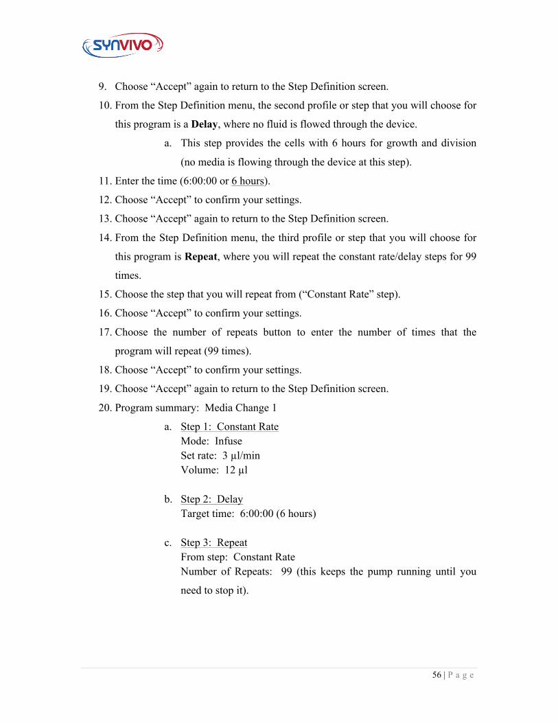
20. Program summary: Media Change 1
a. Step 1: Constant Rate Mode: Infuse Set rate: 3 µl/min Volume: 12 µl
b. Step 2: Delay Target time: 6:00:00 (6 hours)
c. Step 3: Repeat
From step: Constant Rate Number of Repeats: 99 (this keeps the pump running until you
need to stop it).
57 | P a g e
Connecting the devices to a syringe pump:
1. Program the syringe pump (see above).
2. Prepare three 1-mL syringes filled with PneumaCult EX media per device. All
3 channels will be flushed with media using the media change program, so you
will prepare 1 syringe for each channel of the microfluidic device.
3. Attach a length of tubing to each syringe that is long enough to reach from the
syringe pump to the device inside the tissue culture incubator.
4. Infuse the Tygon tubing with the PneumaCult EX cell media.
5. Place the filled syringe into the syringe pump. Tape the end of the tubing onto
the pump, with the end of the tubing pointing up to the ceiling and not touching
any surface.
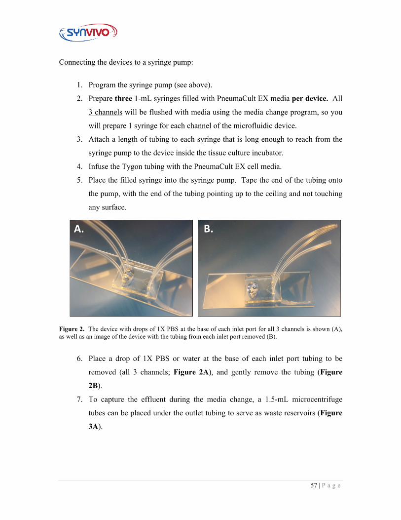
Figure 2. The device with drops of 1X PBS at the base of each inlet port for all 3 channels is shown (A), as well as an image of the device with the tubing from each inlet port removed (B).
6. Place a drop of 1X PBS or water at the base of each inlet port tubing to be
removed (all 3 channels; Figure 2A), and gently remove the tubing (Figure
2B).
7. To capture the effluent during the media change, a 1.5-mL microcentrifuge
tubes can be placed under the outlet tubing to serve as waste reservoirs (Figure
3A).
58 | P a g e
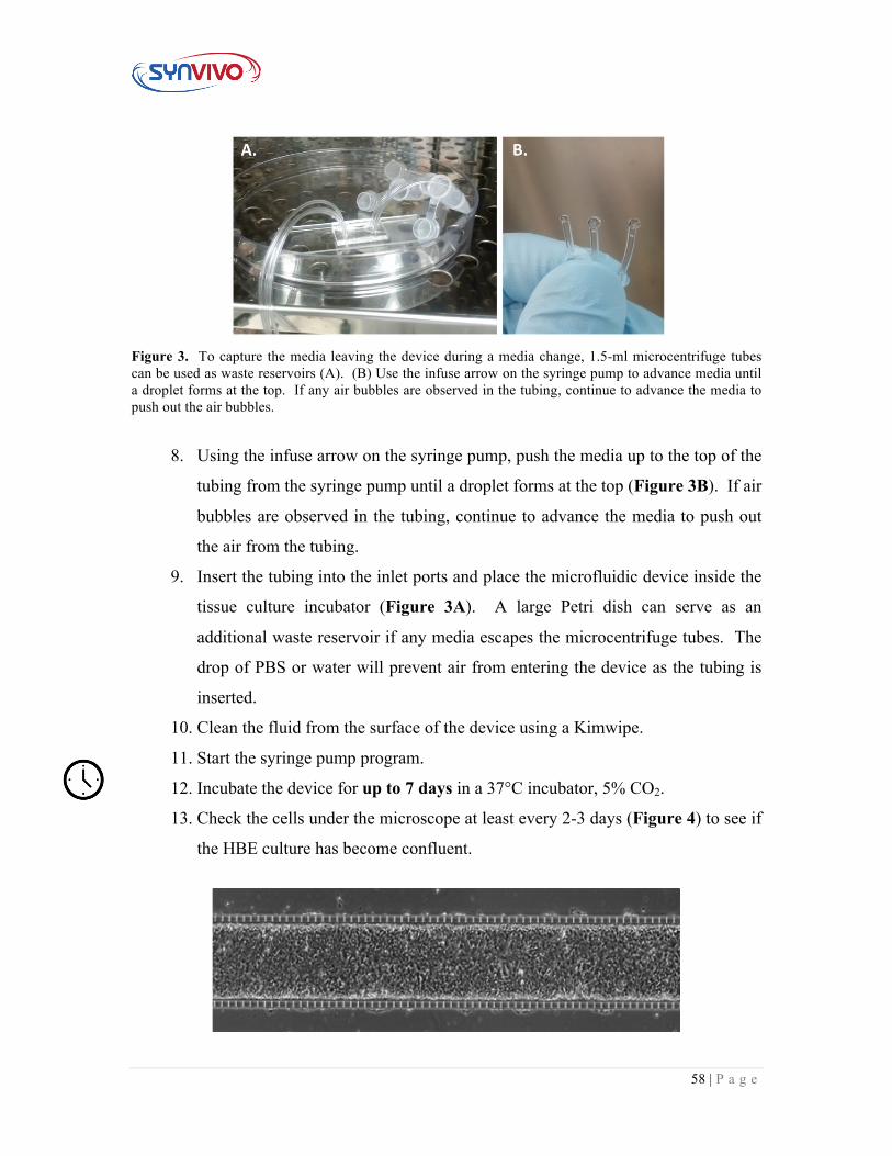
Figure 3. To capture the media leaving the device during a media change, 1.5-ml microcentrifuge tubes can be used as waste reservoirs (A). (B) Use the infuse arrow on the syringe pump to advance media until a droplet forms at the top. If any air bubbles are observed in the tubing, continue to advance the media to push out the air bubbles.
8. Using the infuse arrow on the syringe pump, push the media up to the top of the
tubing from the syringe pump until a droplet forms at the top (Figure 3B). If air
bubbles are observed in the tubing, continue to advance the media to push out
the air from the tubing.
9. Insert the tubing into the inlet ports and place the microfluidic device inside the
tissue culture incubator (Figure 3A). A large Petri dish can serve as an
additional waste reservoir if any media escapes the microcentrifuge tubes. The
drop of PBS or water will prevent air from entering the device as the tubing is
inserted.
10. Clean the fluid from the surface of the device using a Kimwipe.
11. Start the syringe pump program.
12. Incubate the device for up to 7 days in a 37°C incubator, 5% CO2.
13. Check the cells under the microscope at least every 2-3 days (Figure 4) to see if
the HBE culture has become confluent.
59 | P a g e
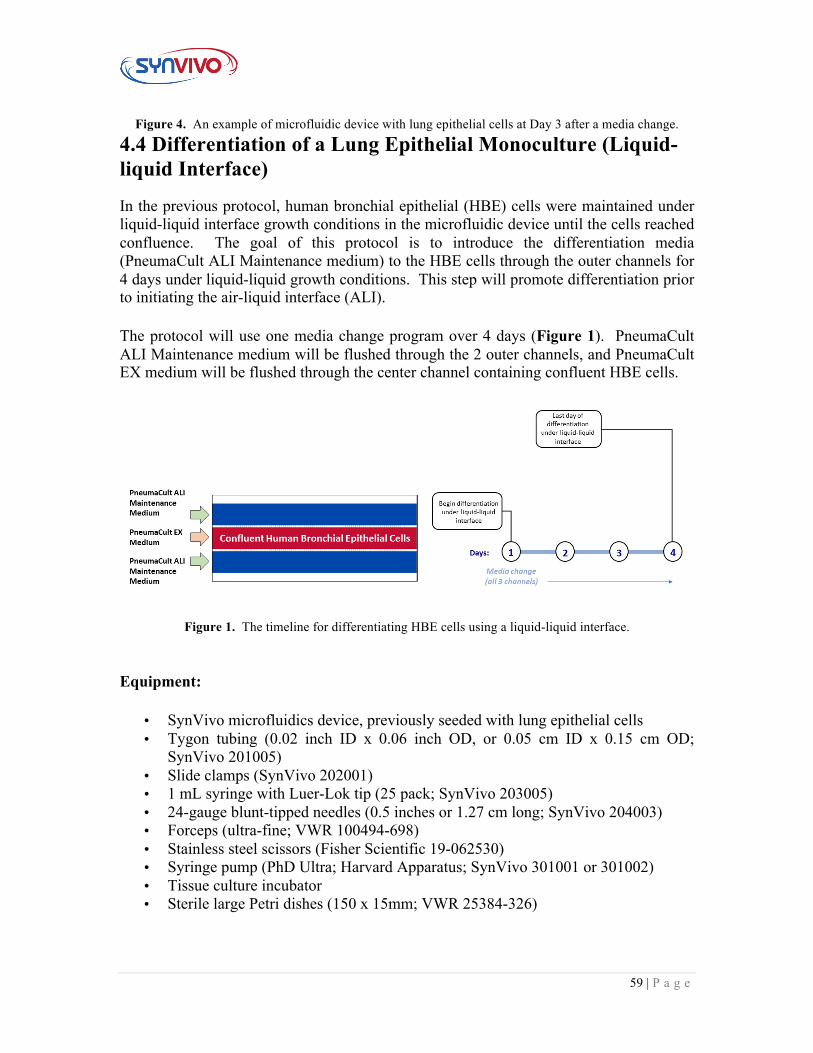
Figure 4. An example of microfluidic device with lung epithelial cells at Day 3 after a media change. 4.4 Differentiation of a Lung Epithelial Monoculture (Liquid-liquid Interface)
In the previous protocol, human bronchial epithelial (HBE) cells were maintained under liquid-liquid interface growth conditions in the microfluidic device until the cells reached confluence. The goal of this protocol is to introduce the differentiation media (PneumaCult ALI Maintenance medium) to the HBE cells through the outer channels for 4 days under liquid-liquid growth conditions. This step will promote differentiation prior to initiating the air-liquid interface (ALI).
The protocol will use one media change program over 4 days (Figure 1). PneumaCult ALI Maintenance medium will be flushed through the 2 outer channels, and PneumaCult EX medium will be flushed through the center channel containing confluent HBE cells.
Figure 1. The timeline for differentiating HBE cells using a liquid-liquid interface.
Equipment:
• SynVivo microfluidics device, previously seeded with lung epithelial cells • Tygon tubing (0.02 inch ID x 0.06 inch OD, or 0.05 cm ID x 0.15 cm OD;
SynVivo 201005) • Slide clamps (SynVivo 202001) • 1 mL syringe with Luer-Lok tip (25 pack; SynVivo 203005) • 24-gauge blunt-tipped needles (0.5 inches or 1.27 cm long; SynVivo 204003) • Forceps (ultra-fine; VWR 100494-698) • Stainless steel scissors (Fisher Scientific 19-062530) • Syringe pump (PhD Ultra; Harvard Apparatus; SynVivo 301001 or 301002) • Tissue culture incubator • Sterile large Petri dishes (150 x 15mm; VWR 25384-326)
60 | P a g e
Reagents:
• 1X PBS without calcium or magnesium (Corning 21040CV) o Can also use HBSS without calcium or magnesium (StemCell
Technologies 37250) • PneumaCult ALI Medium (StemCell Technologies 05001) • Heparin solution (StemCell Technologies 07980) • Hydrocortisone stock solution (StemCell Technologies 07925) • PneumaCult EX Culture Medium (StemCell Technologies 05008)
Protocol:
Preparing PneumaCult ALI Complete Base Medium:
1. Follow manufacturer’s instructions for the preparation of the PneumaCult ALI
Complete Base Medium.
2. Do not exceed the shelf life of the materials.
Preparing PneumaCult ALI Maintenance Medium:
1. Follow manufacturer’s instructions for the preparation of the PneumaCult ALI
Maintenance Medium.
2. Do not exceed the shelf life of the materials.
Media Change #1 (Time frame: 96 hrs):
1. Program the syringe pump with the following media change program:
Program summary: Media Change
Step 1: Constant Rate Mode: Infuse Set rate: 3 µl/min Volume: 12 µl
Step 2: Delay Target time: 6:00:00 (6 hours)
61 | P a g e
Step 3: Repeat From step: Constant Rate
Number of Repeats: 99
(this keeps the pump running until you are ready to stop it)
2. Prepare two 1-mL syringes filled with PneumaCult ALI Maintenance medium
per device and one 1-mL syringe filled with PneumaCult EX medium per
device. All 3 channels will be flushed with media using the media change
program, so you will prepare 1 syringe for each channel of the microfluidic
device.
3. Attach a length of tubing to each syringe that is long enough to reach from the
syringe pump to the device inside the tissue culture incubator.
4. Infuse the Tygon tubing with the medias.
5. Place the filled syringe into the syringe pump. Tape the end of the tubing onto
the pump, with the end of the tubing pointing up to the ceiling and not
touching any surface.
6. Place a drop of 1X PBS or water at the base of each inlet port tubing to be
removed (all 3 channels), and gently remove the tubing.
7. To capture the effluent during the media change, a 1.5-mL microcentrifuge
tubes can be placed under the outlet tubing to serve as waste reservoirs.
8. Using the infuse arrow on the syringe pump, push the media up to the top of
the tubing from the syringe pump until a droplet forms at the top.
9. Insert the tubing into the inlet ports and place the microfluidic device inside
the tissue culture incubator. Make sure the correct media is being fed into the
correct channel (see Figure 1).
10. A large Petri dish can serve as an additional waste reservoir if any media
escapes the microcentrifuge tubes. The drop of PBS or water will prevent air
from entering the device as the tubing is inserted.
11. Clean the fluid from the surface of the device using a Kimwipe.
12. Start the syringe pump program.
13. Incubate the device for 96hrs in a 37°C incubator, 5% CO2.
62 | P a g e
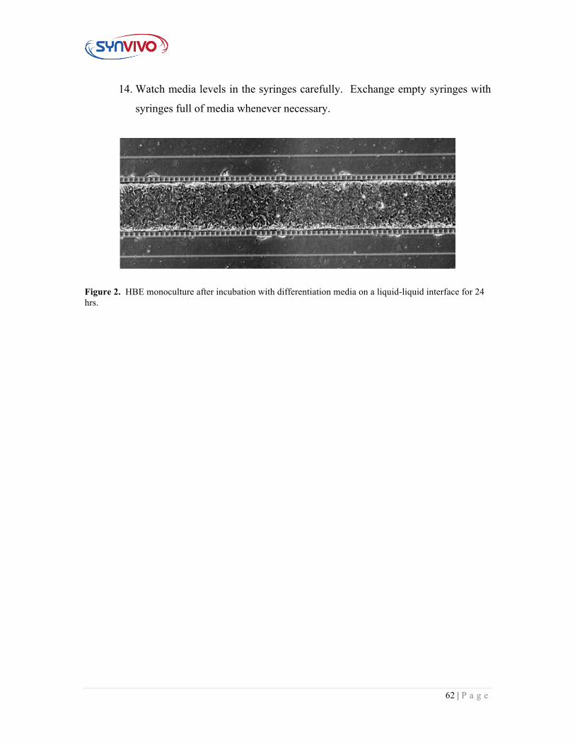
14. Watch media levels in the syringes carefully. Exchange empty syringes with
syringes full of media whenever necessary.
Figure 2. HBE monoculture after incubation with differentiation media on a liquid-liquid interface for 24 hrs.
63 | P a g e
4.5 Differentiation of a Lung Epithelial Monoculture (Air-liquid Interface) This protocol describes how to change from liquid-liquid growth conditions to the air-liquid interface (ALI) for promoting further differentiation of a lung epithelial monoculture.
The air compressor and bubble humidifier should be set up and tested for functionality prior to beginning this protocol (see Sections 2.5 and 2.6 for more details). The lung epithelial cell monoculture should be placed under ALI conditions prior to seeding endothelial cells to establish the co-culture.
Equipment:
• SynVivo microfluidics device, previously seeded with lung epithelial cells • Tygon tubing (0.02 inch ID x 0.06 inch OD, or 0.05 cm ID x 0.15 cm OD;
SynVivo 201005) • Slide clamps (SynVivo 202001) • 1 mL syringe with Luer-Lok tip (25 pack; SynVivo 203005) • 24-gauge blunt-tipped needles (0.5 inches or 1.27 cm long; SynVivo 204003) • Forceps (ultra-fine; VWR 100494-698) • Stainless steel scissors (Fisher Scientific 19-062530) • Syringe pump (PhD Ultra; Harvard Apparatus; SynVivo 301001 or 301002) • Tissue culture incubator • Sterile large Petri dishes (150 x 15mm; VWR 25384-326) • Air compressor and bubble humidifier (see Sections 2.5 and 2.6 for details on
equipment set-up; see Section 2.1 for materials list)
Reagents:
• 1X PBS without calcium or magnesium (Corning 21040CV) o Can also use HBSS without calcium or magnesium (StemCell
Technologies 37250) or HEPES buffered saline solution (Lonza CC-5024) • PneumaCult ALI Medium (StemCell Technologies 05001) • Heparin solution (StemCell Technologies 07980) • Hydrocortisone stock solution (StemCell Technologies 07925)
Protocol:
Preparing PneumaCult ALI Complete Base Medium:
1. Follow manufacturer’s instructions for the preparation of the PneumaCult ALI
Complete Base Medium.
64 | P a g e
2. Do not exceed the shelf life of the materials.
Preparing PneumaCult ALI Maintenance Medium:
1. Follow manufacturer’s instructions for the preparation of the PneumaCult ALI
Maintenance Medium.
2. Do not exceed the shelf life of the materials.
Prepare bubble humidifier for the ALI connection:
1. Turn on the air compressor approximately 24 hours prior to setting up the ALI
in the microfluidic device to increase the air moisture content in the bubbler
system.
2. Make sure there is continuous bubbling in the bubble humidifier.
3. Optional: Check the humidity level inside the tissue culture incubator using a
hygrometer. The humidity level needs to be >90% to keep the ALI culture from
drying out (see Müller L., et al. J Vis Exp. 2013; 80: 50646).
Preparing the media syringes for the air-liquid interface (ALI) set-up:
65 | P a g e
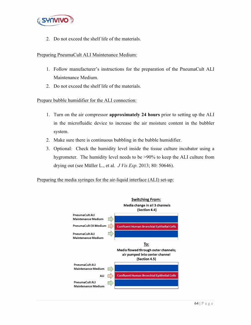
Figure 1. HBE monoculture will be switched to air and PneumaCult ALI maintenance medium will be flowed through the outer channels.
1. Prepare two 1-mL syringes filled with PneumaCult ALI Maintenance medium
per device. The 2 outer channels will be flushed with media while the HBE
cells receive air (Figure 1).
2. Program the syringe pump with the following program:
Program summary: ALI
Step 1: Constant Rate Mode: Infuse Set rate: 0.1−1 µl/min Target time: 48:00:00 (48 hours)
Note: The center channel with the HBE monoculture will need to be flushed with 1X PBS or HEPES buffered saline solution every 48 hours to reduce the buildup of mucus, so the time established in the syringe pump program is set for 48 hours. If the endpoint assay for the tissue does not involve ICC staining, the 48-hour wash step can be omitted.
3. Attach a length of tubing to each syringe that is long enough to reach from the
syringe pump to the device inside the tissue culture incubator.
4. Infuse the Tygon tubing with the PneumaCult ALI maintenance cell media.
5. Place the filled syringe into the syringe pump. Tape the end of the tubing onto
the pump, with the end of the tubing pointing up to the ceiling and not touching
any surface.
Connecting the manifold splitter to the microfluidic devices for ALI:
1. Place a drop of 1X PBS or water at the base of each inlet port tubing to be
removed (center channel), and gently remove the tubing.
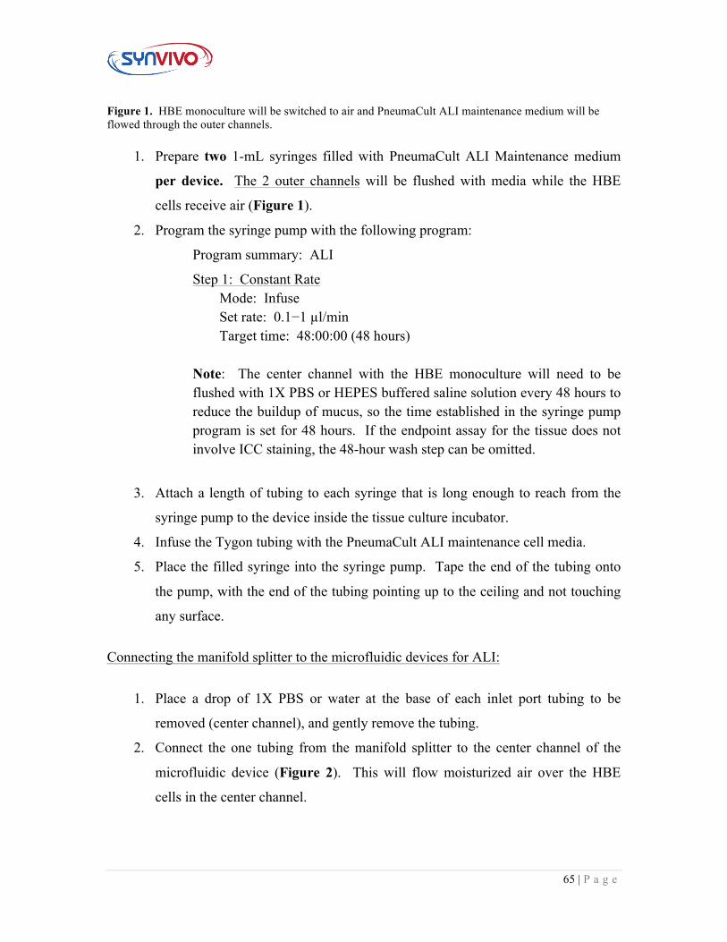
2. Connect the one tubing from the manifold splitter to the center channel of the
microfluidic device (Figure 2). This will flow moisturized air over the HBE
cells in the center channel.
66 | P a g e
Figure 2. Illustration of the manifold splitter and its connection to the bubble humidifier, as well as an image of the manifold splitter connected to the center channel of a microfluidic device through tubing.
Connecting the microfluidic devices to the media syringes:
1. Place a drop of 1X PBS or water at the base of each inlet port tubing to be
removed (2 outer channels), and gently remove the tubing.
2. To capture the effluent during the media change, a 1.5-mL microcentrifuge tubes
can be placed under the outlet tubing to serve as waste reservoirs.
3. Using the infuse arrow on the syringe pump, push the media up to the top of the
tubing from the syringe pump until a droplet forms at the top.
4. Insert the tubing into the inlet ports and place the microfluidic device inside the
tissue culture incubator. A large Petri dish can serve as an additional waste
reservoir if any media escapes the microcentrifuge tubes. The drop of PBS or
water will prevent air from entering the device as the tubing is inserted.
5. Clean the fluid from the surface of the device using a Kimwipe.
6. Start the syringe pump program.
7. Incubate the device for 48hrs in a 37°C incubator, 5% CO2.
67 | P a g e
Washing ALI culture every 48 hours (This step is optional but needed if excess mucus is
secreted which may lead to staining issues for end point assays):
1. Stop the syringe pump.
2. Cut the tubing from all 3 channels.
3. Gently flush the 2 outer channels with 1X PBS or HEPES buffered saline.
4. Gently flush the 2 outer channels with PneumaCult ALI Maintenance Media.
5. Gently flush out the center channel with the HBE cells with 1X PBS or
HEPES buffered saline.
6. Allow the HBE cells to sit in the buffered saline solution for 15−30 minutes
in a 37°C incubator, 5% CO2 (no flow).
7. Connect the center channel back to the manifold splitter by inserting the
tubing into the device. This will place the HBE cells back under air.
8. Replace the media syringes with new syringes filled with PneumaCult ALI
Maintenance media.
9. Place a drop of 1X PBS or water at the base of each inlet port tubing to be
removed (2 outer channels), and gently remove the tubing.
10. Using the infuse arrow on the syringe pump, push the media up to the top of
the tubing from the syringe pump until a droplet forms at the top.
11. Insert the tubing into the inlet ports and place the microfluidic device inside
the tissue culture incubator.
12. Clean the fluid from the surface of the device using a Kimwipe.
13. Start the syringe pump program.
14. Incubate the device for 48hrs in a 37°C incubator, 5% CO2.
15. Repeat the wash cycle over the course of the ALI culture.
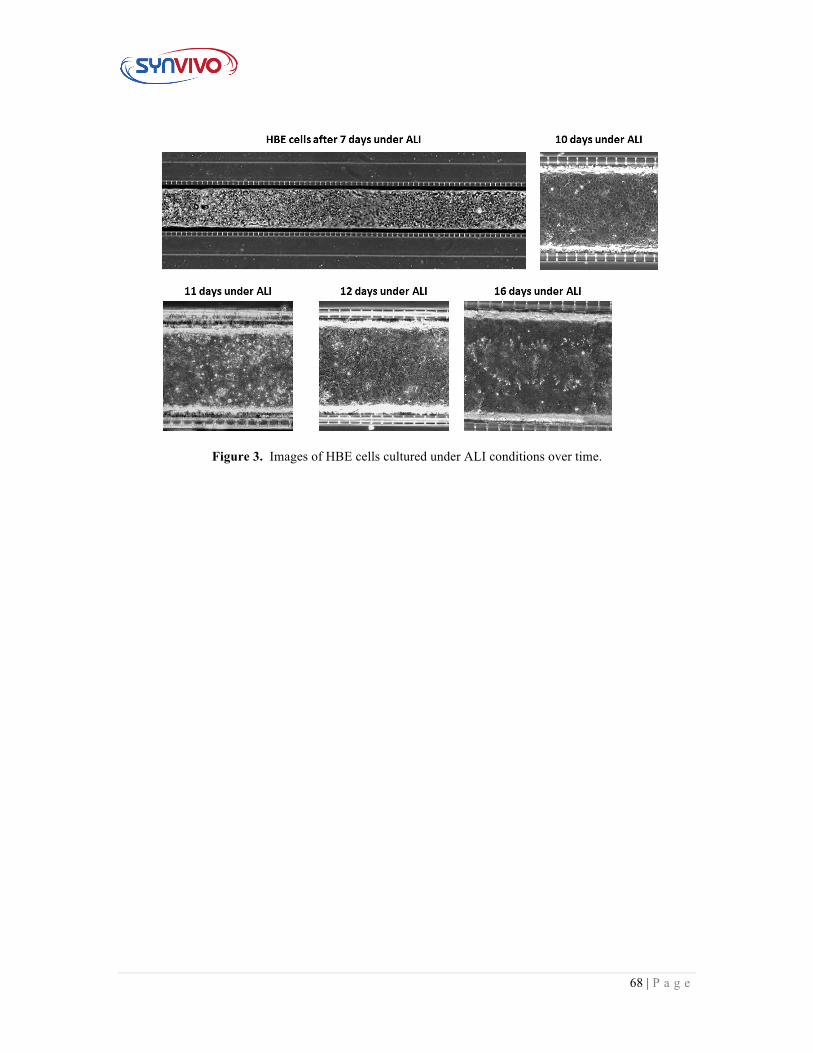
16. Image devices after each wash cycle to observe differentiation (Figure 3).
68 | P a g e
Figure 3. Images of HBE cells cultured under ALI conditions over time.
69 | P a g e
4.6 Re-coating the Microfluidic Devices for Co-Culture Establishment
Principle:
The Type IV collagen coating (50 µg/mL) will be replenished on the outer channels to enhance endothelial cell attachment to the PDMS and allow the formation of a closed vessel during co-culture establishment. This protocol describes how to replenish the coating prior to endothelial cell seeding. During the re-coating process, PneumaCult ALI Maintenance media may be gently flowed through the differentiated HBE cells in the center channel.
Equipment:
• SynVivo microfluidics device, with differentiated HBE monoculture in the center channel
• Tygon tubing (0.02” ID x 0.06” OD; SynVivo 201005) • Slide clamps (SynVivo 202001) • 1 mL syringe with Luer-Lok tip (25 pack; SynVivo 203005) • 24-gauge blunt-tipped needles (0.5” long; SynVivo 204003) • Forceps (ultra-fine; VWR 100494-698) • Stainless steel scissors (Fisher Scientific 19-062530) • T75 flasks (Corning 430641) • Syringe pump (Harvard Apparatus) • Tissue culture incubator
Reagents:
• 1X PBS without calcium or magnesium (Corning 21040CV) • 10X PBS • 0.01M NaOH • Sterile water • Human placental collagen Type IV, reconstituted in 0.02M acetic acid (Sigma,
C5533) • EGM-2MV bullet kit (Lonza CC-3202) • 1X TrpLE Express cell detachment solution, no phenol red (ThermoFisher
Scientific 12604013) o Can be substituted with Trypsin-EDTA for Primary Cells (ATCC PCS-
999-003); follow the manufacturer’s guidelines • HEPES buffered saline (Lonza CC-5022) • PneumaCult ALI Medium (StemCell Technologies 05001) • Heparin solution (StemCell Technologies 07980) • Hydrocortisone stock solution (StemCell Technologies 07925)
70 | P a g e
Protocol: Disclaimer: This protocol describes the seeding concentrations and conditions optimized for HMVEC-Ls. If a different endothelial cell line or primary cell is used, the conditions and coatings described in the protocol should be optimized for the specific cell type.
The following protocols should be carried out within a laminar flow hood as much as possible to maintain sterility.
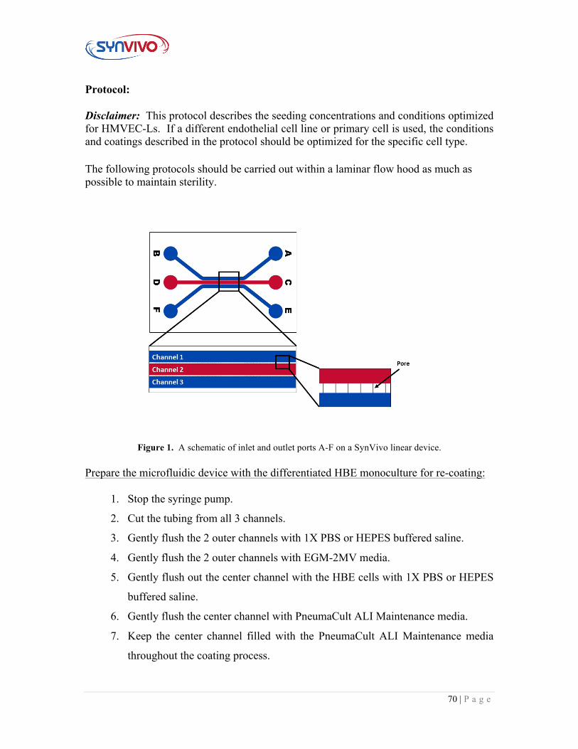
Figure 1. A schematic of inlet and outlet ports A-F on a SynVivo linear device. Prepare the microfluidic device with the differentiated HBE monoculture for re-coating:
1. Stop the syringe pump.
2. Cut the tubing from all 3 channels.
3. Gently flush the 2 outer channels with 1X PBS or HEPES buffered saline.
4. Gently flush the 2 outer channels with EGM-2MV media.
5. Gently flush out the center channel with the HBE cells with 1X PBS or HEPES
buffered saline.
6. Gently flush the center channel with PneumaCult ALI Maintenance media.
7. Keep the center channel filled with the PneumaCult ALI Maintenance media
throughout the coating process.
71 | P a g e
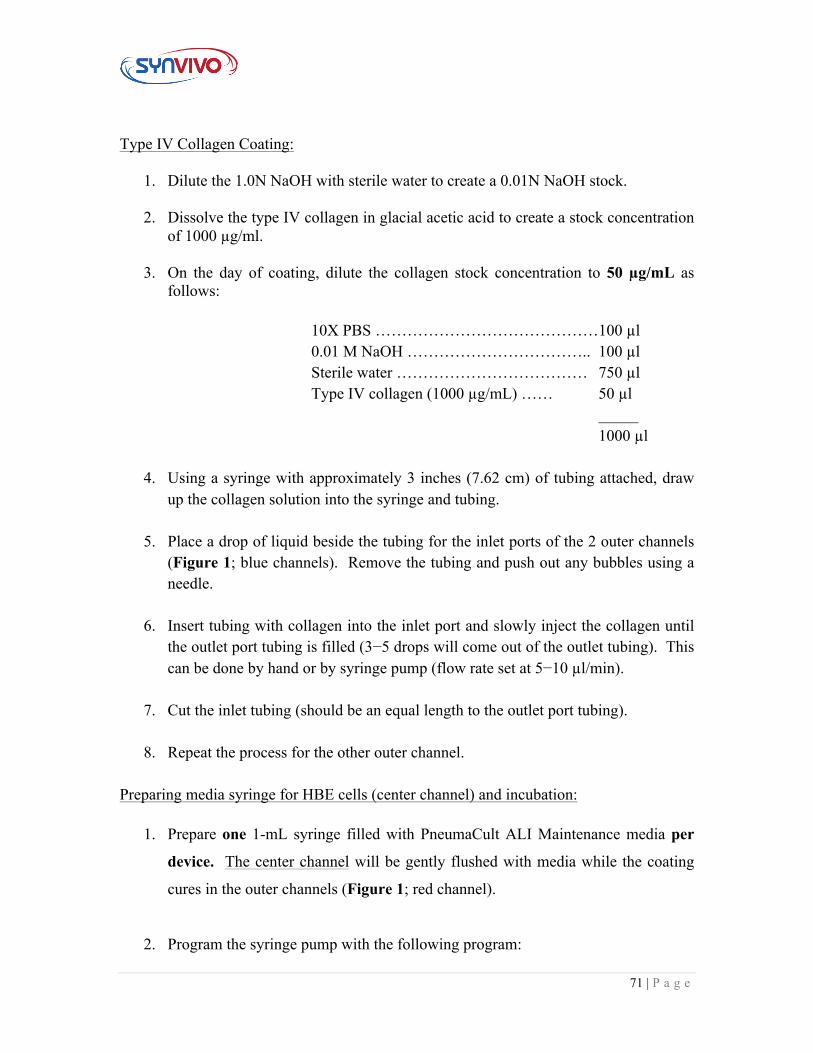
Type IV Collagen Coating:
1. Dilute the 1.0N NaOH with sterile water to create a 0.01N NaOH stock.
2. Dissolve the type IV collagen in glacial acetic acid to create a stock concentration of 1000 µg/ml.
3. On the day of coating, dilute the collagen stock concentration to 50 µg/mL as
follows:
10X PBS ……………………………………100 µl 0.01 M NaOH …………………………….. 100 µl Sterile water ……………………………… 750 µl Type IV collagen (1000 µg/mL) …… 50 µl
_____ 1000 µl
4. Using a syringe with approximately 3 inches (7.62 cm) of tubing attached, draw up the collagen solution into the syringe and tubing.
5. Place a drop of liquid beside the tubing for the inlet ports of the 2 outer channels (Figure 1; blue channels). Remove the tubing and push out any bubbles using a needle.
6. Insert tubing with collagen into the inlet port and slowly inject the collagen until
the outlet port tubing is filled (3−5 drops will come out of the outlet tubing). This can be done by hand or by syringe pump (flow rate set at 5−10 µl/min).
7. Cut the inlet tubing (should be an equal length to the outlet port tubing).
8. Repeat the process for the other outer channel.
Preparing media syringe for HBE cells (center channel) and incubation:
1. Prepare one 1-mL syringe filled with PneumaCult ALI Maintenance media per
device. The center channel will be gently flushed with media while the coating
cures in the outer channels (Figure 1; red channel).
2. Program the syringe pump with the following program:
72 | P a g e
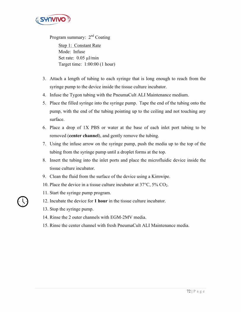
Program summary: 2nd Coating
Step 1: Constant Rate Mode: Infuse Set rate: 0.05 µl/min Target time: 1:00:00 (1 hour)
3. Attach a length of tubing to each syringe that is long enough to reach from the
syringe pump to the device inside the tissue culture incubator.
4. Infuse the Tygon tubing with the PneumaCult ALI Maintenance medium.
5. Place the filled syringe into the syringe pump. Tape the end of the tubing onto the
pump, with the end of the tubing pointing up to the ceiling and not touching any
surface.
6. Place a drop of 1X PBS or water at the base of each inlet port tubing to be
removed (center channel), and gently remove the tubing.
7. Using the infuse arrow on the syringe pump, push the media up to the top of the
tubing from the syringe pump until a droplet forms at the top.
8. Insert the tubing into the inlet ports and place the microfluidic device inside the
tissue culture incubator.
9. Clean the fluid from the surface of the device using a Kimwipe.
10. Place the device in a tissue culture incubator at 37°C, 5% CO2.
11. Start the syringe pump program.
12. Incubate the device for 1 hour in the tissue culture incubator.
13. Stop the syringe pump.
14. Rinse the 2 outer channels with EGM-2MV media.
15. Rinse the center channel with fresh PneumaCult ALI Maintenance media.
73 | P a g e
4.7 Seeding Lung Endothelial Cells to Form a Co-Culture Principle:
After the HBE cells have been differentiated under ALI model for at least 7 days, the human microvascular lung endothelial cells (HMVEC-Ls) can be seeded into the two outer channels to form the co-culture. Endothelial media formulations will be cell-type and manufacturer specific, so follow the manufacturer’s guidelines for cell seeding and propagation.
Equipment:
• SynVivo microfluidics device, with differentiated HBE monoculture in the center channel
• Tygon tubing (0.02” ID x 0.06” OD; SynVivo 201005) • Slide clamps (SynVivo 202001) • 1 mL syringe with Luer-Lok tip (25 pack; SynVivo 203005) • 24-gauge blunt-tipped needles (0.5” long; SynVivo 204003) • Forceps (ultra-fine; VWR 100494-698) • Stainless steel scissors (Fisher Scientific 19-062530) • T75 flasks (Corning 430641) • Syringe pump (Harvard Apparatus) • Tissue culture incubator
Primary Cells:
• Human microvascular lung endothelial cells (HMVEC-Ls)
Reagents:
• 1X PBS without calcium or magnesium (Corning 21040CV) • 10X PBS • EGM-2MV bullet kit (Lonza CC-3202) • 1X TrpLE Express cell detachment solution, no phenol red (ThermoFisher
Scientific 12604013) o Can be substituted with Trypsin-EDTA for Primary Cells (ATCC PCS-
999-003); follow the manufacturer’s guidelines • HEPES buffered saline (Lonza CC-5022) • PneumaCult ALI Medium (StemCell Technologies 05001) • Heparin solution (StemCell Technologies 07980) • Hydrocortisone stock solution (StemCell Technologies 07925)
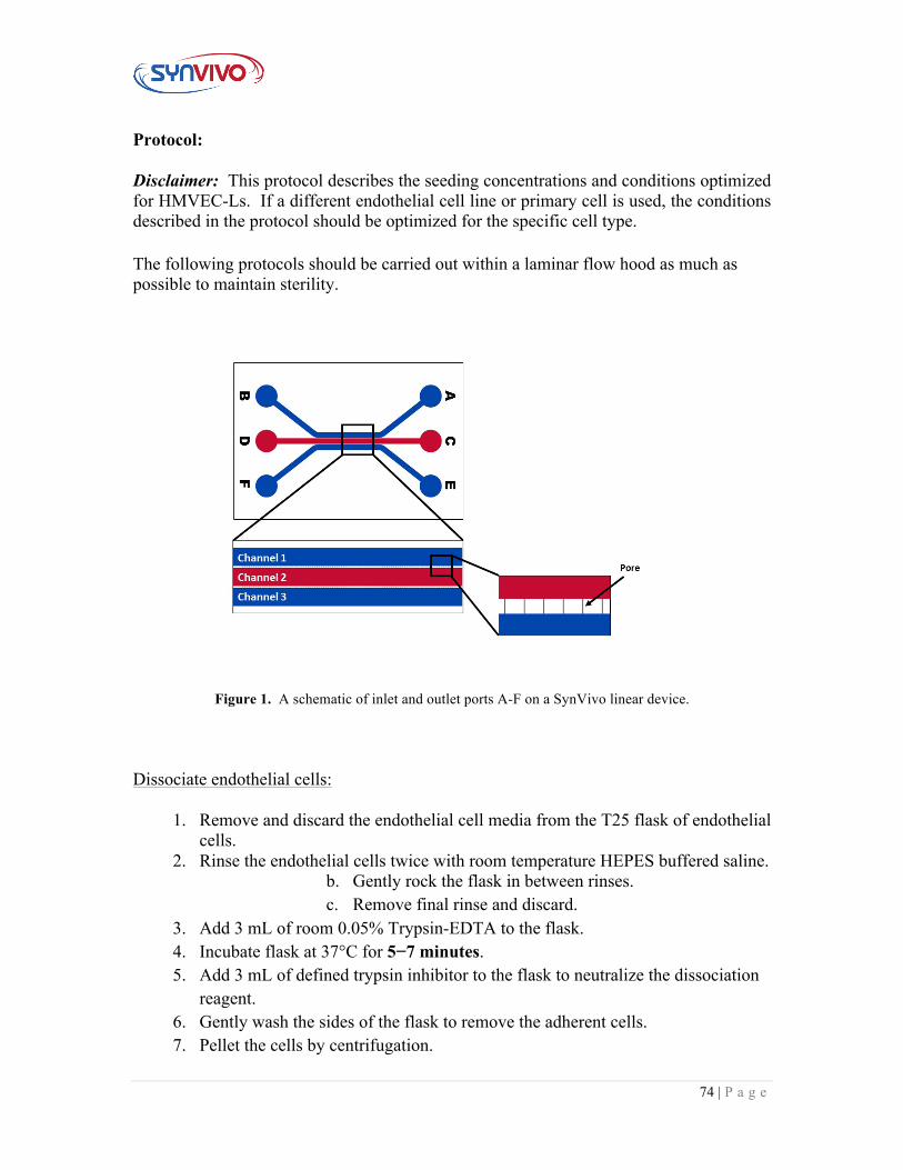
74 | P a g e
Protocol: Disclaimer: This protocol describes the seeding concentrations and conditions optimized for HMVEC-Ls. If a different endothelial cell line or primary cell is used, the conditions described in the protocol should be optimized for the specific cell type.
The following protocols should be carried out within a laminar flow hood as much as possible to maintain sterility.
Figure 1. A schematic of inlet and outlet ports A-F on a SynVivo linear device. Dissociate endothelial cells:
1. Remove and discard the endothelial cell media from the T25 flask of endothelial cells.
2. Rinse the endothelial cells twice with room temperature HEPES buffered saline. b. Gently rock the flask in between rinses. c. Remove final rinse and discard.
3. Add 3 mL of room 0.05% Trypsin-EDTA to the flask. 4. Incubate flask at 37°C for 5−7 minutes. 5. Add 3 mL of defined trypsin inhibitor to the flask to neutralize the dissociation
reagent. 6. Gently wash the sides of the flask to remove the adherent cells. 7. Pellet the cells by centrifugation.
75 | P a g e
d. Use 200 x g (1000 RPM) for 5−10 minutes at room temperature (do not use speeds greater than 1000 RPM).
8. Remove the media, leaving behind at least 100 µl to cover the cell pellet. 9. Wash the cells twice with 5 mL complete endothelial cell media, and pellet the
cells by centrifugation. e. Use 200 x g for 5 minutes at room temperature (do not use
speeds greater than 1000 RPM). 10. Perform a cell count. 11. Calculate the volume of cell suspension needed to obtain a cell concentration of
1−5 x 10⁶ cells/ml. Seeding endothelial cells into the SynVivo devices:
1. Flush the 2 outer channels of the pre-coated SynVivo device with complete endothelial cell media (i.e. EGM2-MV).
2. Centrifuge the cells for 5 minutes at 0.2 x g at room temperature (no more than 1000 RPM).
3. Resuspend the cell pellet in the volume of complete endothelial cell media to achieve 1−5 x 10⁶ cells/ml.
a. The cell solution should have the appearance of frosted glass, which will indicate a dense cell concentration.
4. Place a drop of liquid beside the tubing for the inlet port of one of the outer channels (Figure 1; blue channels). Remove the tubing and push out any bubbles using a needle.
5. Draw back the plunger of a 1-mL syringe to the 0.3 mL mark. 6. If seeding by hand:
a. Load the Tygon tubing with the previously prepared cell suspension. Draw up enough cells to fill the tubing, but do not bring the cells into the syringe barrel.
b. Make sure that the tubing is free of air bubbles. c. Push the cell mixture out until it is flush with the end of the tubing.
7. If seeding by a syringe pump: a. Mount the syringe onto a syringe pump. b. Load the Tygon tubing with the previously prepared cell suspension,
using the withdraw button on the syringe pump (double arrows pointing to the left).
8. Draw up enough cells to fill the tubing, but do not bring the cells into the syringe barrel.
a. Make sure that the tubing is free of air bubbles. b. Using the rapid infuse button on the syringe pump (double arrows
pointing to the right), make sure the cell mixture is flush with the end of the tubing.
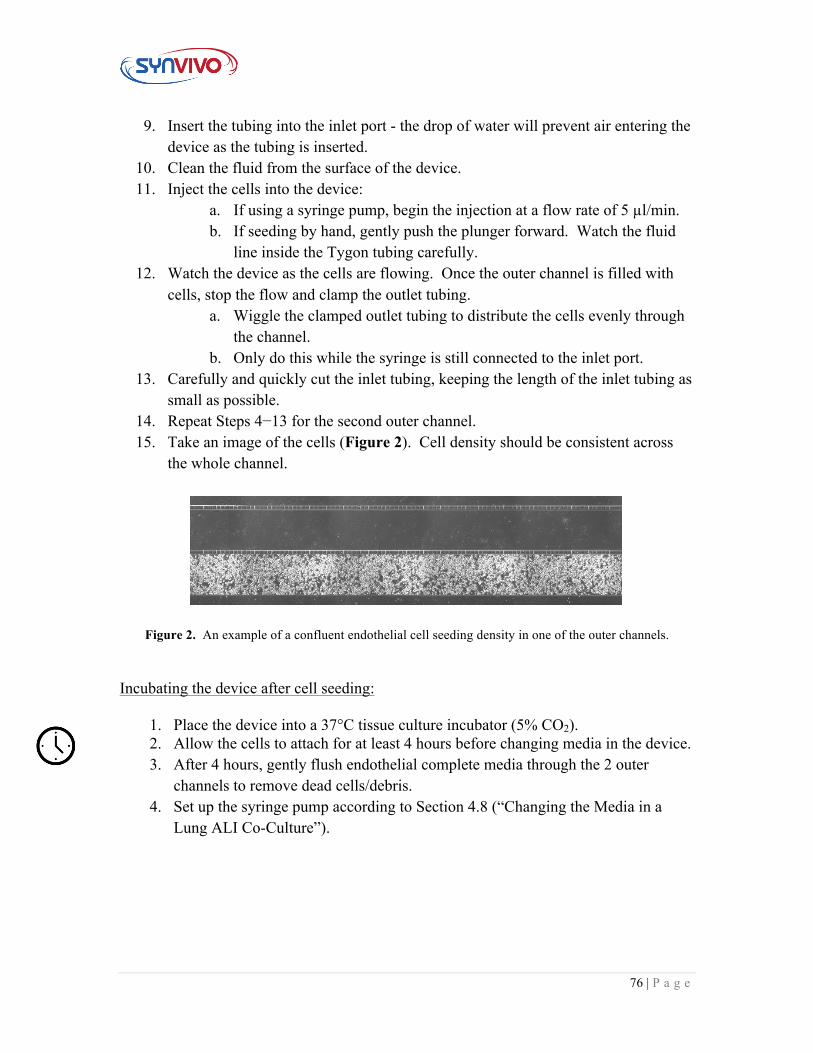
76 | P a g e
9. Insert the tubing into the inlet port - the drop of water will prevent air entering the device as the tubing is inserted.
10. Clean the fluid from the surface of the device. 11. Inject the cells into the device:
a. If using a syringe pump, begin the injection at a flow rate of 5 µl/min. b. If seeding by hand, gently push the plunger forward. Watch the fluid
line inside the Tygon tubing carefully. 12. Watch the device as the cells are flowing. Once the outer channel is filled with
cells, stop the flow and clamp the outlet tubing. a. Wiggle the clamped outlet tubing to distribute the cells evenly through
the channel. b. Only do this while the syringe is still connected to the inlet port.
13. Carefully and quickly cut the inlet tubing, keeping the length of the inlet tubing as small as possible.
14. Repeat Steps 4−13 for the second outer channel. 15. Take an image of the cells (Figure 2). Cell density should be consistent across
the whole channel.
Figure 2. An example of a confluent endothelial cell seeding density in one of the outer channels.
Incubating the device after cell seeding:
1. Place the device into a 37°C tissue culture incubator (5% CO2). 2. Allow the cells to attach for at least 4 hours before changing media in the device. 3. After 4 hours, gently flush endothelial complete media through the 2 outer
channels to remove dead cells/debris. 4. Set up the syringe pump according to Section 4.8 (“Changing the Media in a
Lung ALI Co-Culture”).
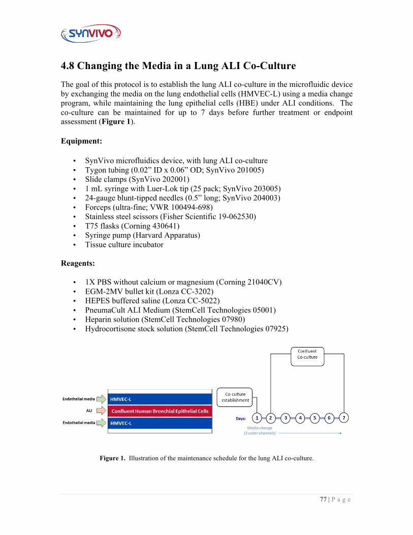
77 | P a g e
4.8 Changing the Media in a Lung ALI Co-Culture
The goal of this protocol is to establish the lung ALI co-culture in the microfluidic device by exchanging the media on the lung endothelial cells (HMVEC-L) using a media change program, while maintaining the lung epithelial cells (HBE) under ALI conditions. The co-culture can be maintained for up to 7 days before further treatment or endpoint assessment (Figure 1).
Equipment:
• SynVivo microfluidics device, with lung ALI co-culture • Tygon tubing (0.02” ID x 0.06” OD; SynVivo 201005) • Slide clamps (SynVivo 202001) • 1 mL syringe with Luer-Lok tip (25 pack; SynVivo 203005) • 24-gauge blunt-tipped needles (0.5” long; SynVivo 204003) • Forceps (ultra-fine; VWR 100494-698) • Stainless steel scissors (Fisher Scientific 19-062530) • T75 flasks (Corning 430641) • Syringe pump (Harvard Apparatus) • Tissue culture incubator
Reagents:
• 1X PBS without calcium or magnesium (Corning 21040CV) • EGM-2MV bullet kit (Lonza CC-3202) • HEPES buffered saline (Lonza CC-5022) • PneumaCult ALI Medium (StemCell Technologies 05001) • Heparin solution (StemCell Technologies 07980) • Hydrocortisone stock solution (StemCell Technologies 07925)
Figure 1. Illustration of the maintenance schedule for the lung ALI co-culture.
78 | P a g e
Preparing the media syringes for the air-liquid interface (ALI) set-up:
1. Prepare two 1-mL syringes filled with endothelial cell complete medium per
device. The 2 outer channels will be flushed with media while the HBE cells
receive air (Figure 1).
2. Program the syringe pump with the following program:
Program summary: Media Change_ALI
Step 1: Constant Rate Mode: Infuse Set rate: 0.1−1 µl/min Target volume: 12 µl Step 2: Delay Target time: 4:00:00 (4 hours)
Note: The flow rate is listed as a range (0.1−1 µl/min) to account for different cell sources/lot numbers. Different flow rates should be tested and an optimal flow rate determined for each cell source.
3. Attach a length of tubing to each syringe that is long enough to reach from
the syringe pump to the device inside the tissue culture incubator.
4. Infuse the Tygon tubing with the PneumaCult ALI maintenance cell media.
5. Place the filled syringe into the syringe pump. Tape the end of the tubing
onto the pump, with the end of the tubing pointing up to the ceiling and not
touching any surface.
79 | P a g e
Section 5:
Endpoint Assays
80 | P a g e
5.1 Epithelial Permeability Assay for the Lung ALI Model Principle:
Capillary lung endothelium provides a semipermeable barrier in the alveoli that allows for fluid exchange [1, 2]. In contrast, alveolar epithelial cells form a tight barrier that restricts fluid transport to air spaces. Changes in epithelial permeability can lead to pulmonary edema and acute lung injury [2]. One method used to visualize microvessel permeability is to introduce a solution with a fluorescent tracer (e.g. FITC-dextran) into a vessel and observe its diffusion across the endothelial or epithelial barrier using fluorescence microscopy [3]. The molecular weight of the fluorescent tracer can influence its permeability through tissue-specific barriers, e.g. 4 kDa FITC-dextran can pass through a healthy intestinal epithelial barrier but a 70 kDa molecule cannot [4]. This protocol will describe how to visualize FITC-dextran diffusion across a human bronchial epithelial vessel and into the outer channels in a co-culture model, as well as how to quantify epithelial permeability by measuring changes in relative fluorescence intensity across a barrier.
Equipment:
• SynVivo IMN linear device, previously seeded with endothelial cells (monoculture), or an endothelial-epithelial cell co-culture
• Tygon tubing (0.02” ID x 0.06” OD; SynVivo 201005) • Slide clamps (SynVivo 202001) • 1 mL syringe with Luer-Lok tip (25 pack; SynVivo 203005) • 24-gauge blunt-tipped needles (0.5” long; SynVivo 204003) • Forceps (ultra-fine; VWR 100494-698) • Stainless steel scissors (Fisher Scientific NC0806723) • Syringe pump (PhD Ultra; Harvard Apparatus; SynVivo 301001 or 301002) • Tissue culture incubator • Fluorescence microscope (Ex/Em 485/520 nm)
Reagents:
• 1X PBS without calcium or magnesium (Corning 21040CV) • EBM Basal Medium, Phenol Red Free (Lonza CC3129) • 4kDa FITC-Dextran (Sigma Aldrich 46944)
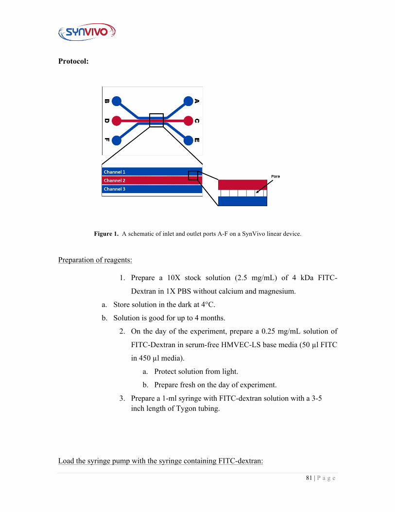
81 | P a g e
Protocol:
Figure 1. A schematic of inlet and outlet ports A-F on a SynVivo linear device. Preparation of reagents:
1. Prepare a 10X stock solution (2.5 mg/mL) of 4 kDa FITC-
Dextran in 1X PBS without calcium and magnesium.
a. Store solution in the dark at 4°C.
b. Solution is good for up to 4 months.
2. On the day of the experiment, prepare a 0.25 mg/mL solution of
FITC-Dextran in serum-free HMVEC-LS base media (50 µl FITC
in 450 µl media).
a. Protect solution from light.
b. Prepare fresh on the day of experiment.
3. Prepare a 1-ml syringe with FITC-dextran solution with a 3-5 inch length of Tygon tubing.
Load the syringe pump with the syringe containing FITC-dextran:
82 | P a g e
1. Treat devices with compounds or controls prior to the beginning
of this assay.
2. Carefully flush the endothelial channel (e.g. Channel 1 or 3;
Figure 1) with fresh serum-free media prior to the start of the
assay.
3. Attach a length of tubing to the syringe that is long enough to
reach from the syringe pump to the device.
4. Infuse the Tygon tubing with the FITC-dextran solution.
5. Place the filled syringe into the syringe pump.
6. Program the syringe pump to infuse at a flow rate of 0.1 µl/min.
7. Before connecting the devices to the syringe pump: Take
phase and fluorescence images (Ex/Em 485/520 nm).
a. These images will provide background fluorescence
signals (if any treatments emit within the same range
as FITC, this will be detected as well).
Infuse the center channel of each device (containing epithelial cells) with FITC-dextran:
1. Place a drop of liquid beside the inlet tubing of the center channel (Figure 1; Channel 2).
2. Gently remove the tubing and push out any bubbles using a needle.
3. Unclamp the outlet port for the center channel. 4. Insert the tubing of the syringe with FITC-dextran into the inlet
port - the drop of water will prevent air entering the device as the tubing is inserted.
5. Clean the fluid from the surface of the device. 6. Inject the fluorescent dye into the device at a flow rate of 0.5 µl/min.
7. Using the microscope, observe the center channel as it fills with FITC-dextran.
8. Once the center channel is completely filled with fluorescent dye, stop the flow from the syringe pump.
9. Carefully and quickly cut the inlet tubing to separate the device from the syringe.
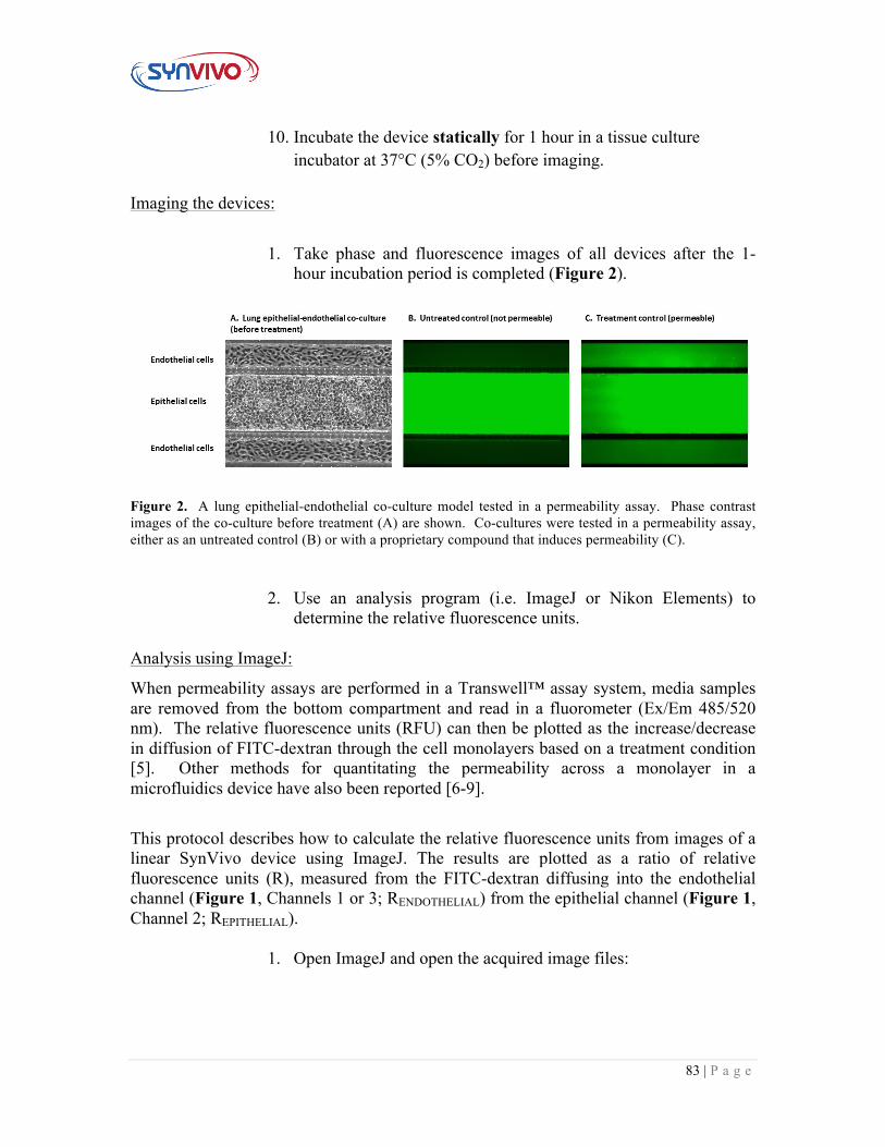
83 | P a g e
10. Incubate the device statically for 1 hour in a tissue culture incubator at 37°C (5% CO2) before imaging.
Imaging the devices:
1. Take phase and fluorescence images of all devices after the 1-hour incubation period is completed (Figure 2).
Figure 2. A lung epithelial-endothelial co-culture model tested in a permeability assay. Phase contrast images of the co-culture before treatment (A) are shown. Co-cultures were tested in a permeability assay, either as an untreated control (B) or with a proprietary compound that induces permeability (C).
2. Use an analysis program (i.e. ImageJ or Nikon Elements) to determine the relative fluorescence units.
Analysis using ImageJ:
When permeability assays are performed in a Transwell™ assay system, media samples are removed from the bottom compartment and read in a fluorometer (Ex/Em 485/520 nm). The relative fluorescence units (RFU) can then be plotted as the increase/decrease in diffusion of FITC-dextran through the cell monolayers based on a treatment condition [5]. Other methods for quantitating the permeability across a monolayer in a microfluidics device have also been reported [6-9].
This protocol describes how to calculate the relative fluorescence units from images of a linear SynVivo device using ImageJ. The results are plotted as a ratio of relative fluorescence units (R), measured from the FITC-dextran diffusing into the endothelial channel (Figure 1, Channels 1 or 3; RENDOTHELIAL) from the epithelial channel (Figure 1, Channel 2; REPITHELIAL).
1. Open ImageJ and open the acquired image files:
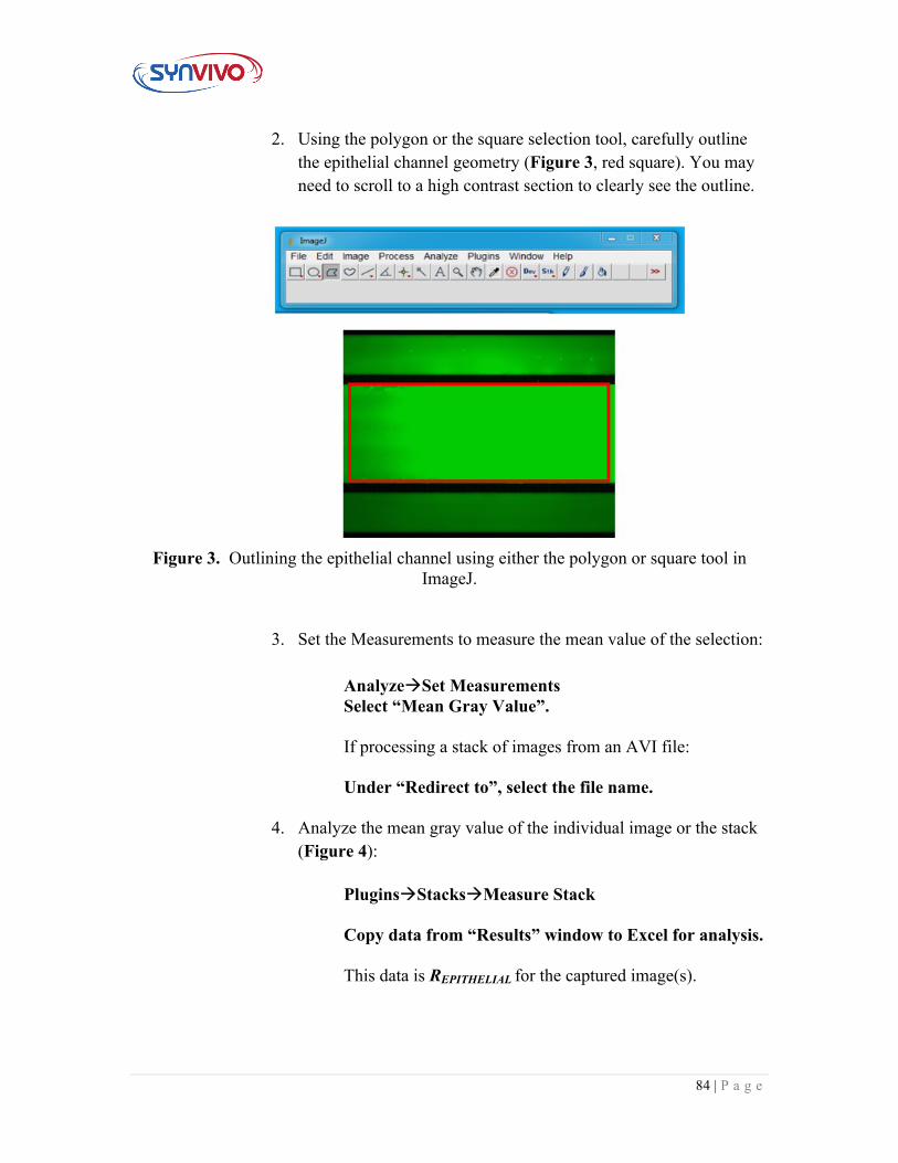
84 | P a g e
2. Using the polygon or the square selection tool, carefully outline the epithelial channel geometry (Figure 3, red square). You may need to scroll to a high contrast section to clearly see the outline.
Figure 3. Outlining the epithelial channel using either the polygon or square tool in
ImageJ.
3. Set the Measurements to measure the mean value of the selection:
AnalyzeàSet Measurements Select “Mean Gray Value”. If processing a stack of images from an AVI file: Under “Redirect to”, select the file name.
4. Analyze the mean gray value of the individual image or the stack (Figure 4):
PluginsàStacksàMeasure Stack Copy data from “Results” window to Excel for analysis. This data is REPITHELIAL for the captured image(s).
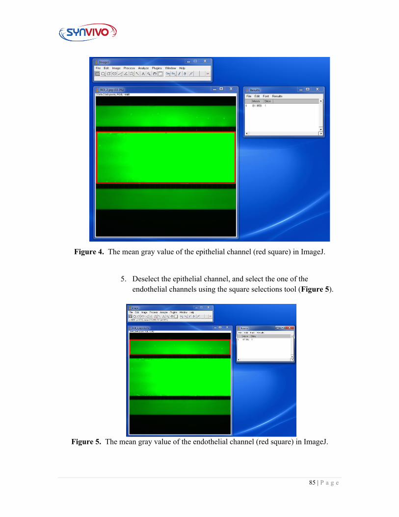
85 | P a g e
Figure 4. The mean gray value of the epithelial channel (red square) in ImageJ.
5. Deselect the epithelial channel, and select the one of the endothelial channels using the square selections tool (Figure 5).
Figure 5. The mean gray value of the endothelial channel (red square) in ImageJ.
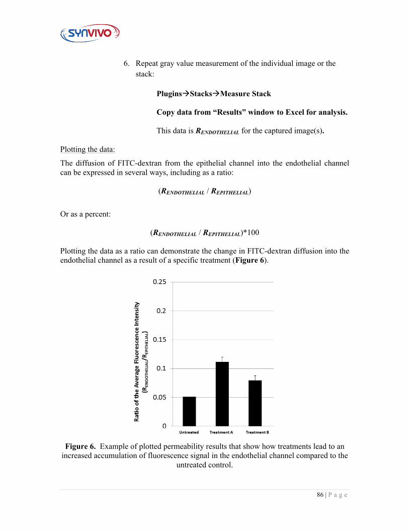
86 | P a g e
6. Repeat gray value measurement of the individual image or the stack:
PluginsàStacksàMeasure Stack Copy data from “Results” window to Excel for analysis. This data is RENDOTHELIAL for the captured image(s).
Plotting the data:
The diffusion of FITC-dextran from the epithelial channel into the endothelial channel can be expressed in several ways, including as a ratio:
(RENDOTHELIAL / REPITHELIAL)
Or as a percent:
(RENDOTHELIAL / REPITHELIAL)*100 Plotting the data as a ratio can demonstrate the change in FITC-dextran diffusion into the endothelial channel as a result of a specific treatment (Figure 6).
Figure 6. Example of plotted permeability results that show how treatments lead to an
increased accumulation of fluorescence signal in the endothelial channel compared to the untreated control.
87 | P a g e
Supporting Information:
1. Herrero, R., G. Sanchez, and J. A. Lorente. 2018. New insights into the mechanisms of pulmonary edema in acute lung injury. Ann Transl Med. 6(2):32.
2. Frank, J. A. 2012. Claudins and alveolar epithelial barrier function in the lung. Ann N Y Acad Sci. 1257:175-183.
3. Yuan, S. Y., and R. R. Rigor. Regulation of Endothelial Barrier Function. San Rafael (CA): Morgan & Claypool Life Sciences; 2010.
4. Woting A., and M. Blaut. 2018. Small intestinal permeability and gut-transit time determined with low and high molecular weight fluorescein isothiocyanate-dextrans in C3H mice. Nutrients. 10(6): 685.
5. Monaghan-Benson, E., and K. Burridge. 2009. The regulation of vascular endothelial growth factor-induced microvascular permeability requires Rac and reactive oxygen species. J Biol Chem. 284(38): 25602-25611.
6. Tang, Y., F. Soroush, J. B. Sheffield, B. Wang, B. Prabhakarpandian, and M. F. Kiani. 2017. A biomimetic microfluidic tumor microenvironment platform mimicking the EPR effect for rapid screening of drug delivery systems. Sci Rep. 7:9359.
7. Yuan H., M. W. Gaber, T. McColgan, M. D. Naimark, M. F. Kiani, and T. E. Merchant. 2003. Radiation-induced permeability and leukocyte adhesion in the rat blood–brain barrier: modulation with anti-ICAM-1 antibodies. Brain Res. 969: 59-69.
8. Terrell-Hall, T. B., A. G. Ammer, J. I. Griffith, and P. R. Lockman. 2017. Permeability across a novel microfluidic blood-tumor barrier model. Fluids Barriers CNS, 14(1):3.
9. Terrell-Hall, T. B., M. I. Nounou, F. El-Amrawy, J. I. G. Griffith, and P. R. Lockman. 2017. Trastuzumab distribution in an in-vivo and in-vitro model of brain metastases of breast cancer. Oncotarget. 8(48): 83734-83744.
88 | P a g e
5.2 Fixing Cells in the Devices Principle:
The following protocol describes how to fix cells in the devices after the permeability assay.
Equipment:
• SynVivo microfluidics device, previously seeded with endothelial and/or epithelial cells
• Tygon tubing (0.02” ID x 0.06” OD; SynVivo 201005) • Slide clamps (SynVivo 202001) • 1 mL syringe with Luer-Lok tip (25 pack; SynVivo 203005) • 24-gauge blunt-tipped needles (0.5” long; SynVivo 204003) • Forceps (ultra-fine; VWR 100494-698) • Stainless steel scissors (Fisher Scientific NC0806723) • Aluminum foil • Kimwipes (Fisher Scientific 06-666A) • Parafilm laboratory wrapping film (Fisher Scientific 13-374-12) • Disposable Petri dishes (Corning 351007) • Refrigerator
Reagents:
• 1X PBS without calcium or magnesium (Corning 21040CV) • 4% formaldehyde (diluted from 16% stock; ThermoFisher Scientific 28908)
Fixing cells in the SynVivo device:
1. Take a phase image of the cells to record cellular morphology and
density prior to staining.
2. Prepare 4% formaldehyde from a 16% stock solution of
methanol-free formaldehyde.
a. Add 2.75 mL of 16% methanol-free formaldehyde to 8.25 mL of 1X PBS.
i. Prepare solution just before each assay.
3. Flush all channels of the SynVivo device by hand with 1X PBS
(without calcium or magnesium) to remove the 70 kDa FITC-
dextran and any cellular debris.
89 | P a g e
a. Gently push the plunger of a 1-mL syringe filled with
PBS, until 6 drops come out of the outlet tubing for each
channel.
4. Gently infuse all channels of the SynVivo device with 4% paraformaldehyde (by hand).
a. Gently push the plunger of a 1-mL syringe filled with 4% paraformaldehyde.
b. Let 3 drops come out of the outlet tubing for each channel. 5. Incubate the device at room temperature for 15 minutes.
a. Cover the devices with aluminum foil during this incubation period.
6. Wash all channels of the SynVivo device by hand with 1X PBS
(without calcium or magnesium).
a. Gently push the plunger of a 1-mL syringe filled with
PBS, until 6 drops come out of the outlet tubing for each
channel.
7. The assay may be stopped at this point, if needed: a. Place devices in a sterile Petri dish. b. Unclamp all tubing.
i. PDMS must be kept hydrated, or evaporation will lead to bubbles forming or drying out the cells.
ii. Unclamping the tubing allows the liquid to flow back into the device, which will hydrate the channels and chambers.
c. Put a PBS-soaked KimWipe in the Petri dish to keep the devices hydrated.
d. Seal the dish with the device inside using Parafilm. e. Store device at 4°C overnight.
90 | P a g e
5.3 Immunocytochemistry (ICC) Staining Principle:
Antibody staining is a common way to distinguish between cells within a co-culture. Lung epithelial cells can be stained with anti-E-cadherin antibodies. Endothelial tight junctions can be stained with anti-VE-cadherin or anti-ZO1 (zonula occludens-1) antibodies.
Direct staining involves using primary antibodies conjugated to a fluorophore. Indirect staining uses a non-conjugated primary antibody, followed by staining with a conjugated secondary antibody. This protocol describes an indirect staining method, but either direct or indirect staining can be used effectively in the SynVivo devices.
Equipment:
• SynVivo microfluidics device, previously seeded with HMVEC and NHBE cells • Tygon tubing (0.02” ID x 0.06” OD; SynVivo 201005) • Slide clamps (SynVivo 202001) • 1 mL syringe with Luer-Lok tip (25 pack; SynVivo 203005) • 24-gauge blunt-tipped needles (0.5” long; SynVivo 204003) • Forceps (ultra-fine; VWR 100494-698) • Stainless steel scissors (Fisher Scientific NC0806723) • Aluminum foil • Kimwipes (Fisher Scientific 06-666A) • Parafilm laboratory wrapping film (Fisher Scientific 13-374-12) • Disposable Petri dishes (Corning 351007) • 0.22 µm pore Steriflip-GV centrifuge tube top filter unit (EMD Millipore
SE1M179M6) • Refrigerator
Reagents:
• 1X PBS without calcium or magnesium (Corning 21040CV) • 4% formaldehyde (diluted from 16% stock; ThermoFisher Scientific 28908) • 0.1% Triton X-100 (diluted from stock solution; VWR A16046-AE) • Appropriate primary and secondary antibodies (Table 1) • NucBlue ReadyProbes reagent (ThermoFisher Scientific R37605 or R37606)
Protocol: Antibody staining should be carried out within a laminar flow hood. The antibodies and stains used in this assay are listed in Table 1. These antibodies are specific for a human model using human bronchial microvascular endothelial cells (hBMECs), as well as human bronchial epithelial cells (HBEs).
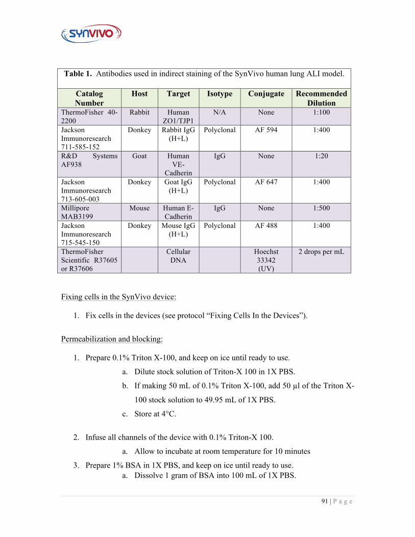
91 | P a g e
Table 1. Antibodies used in indirect staining of the SynVivo human lung ALI model.
Catalog Number
Host Target Isotype Conjugate Recommended Dilution
ThermoFisher 40-2200
Rabbit Human ZO1/TJP1
N/A None 1:100
Jackson Immunoresearch 711-585-152
Donkey Rabbit IgG (H+L)
Polyclonal AF 594 1:400
R&D Systems AF938
Goat Human VE-
Cadherin
IgG None 1:20
Jackson Immunoresearch 713-605-003
Donkey Goat IgG (H+L)
Polyclonal AF 647 1:400
Millipore MAB3199
Mouse Human E-Cadherin
IgG None 1:500
Jackson Immunoresearch 715-545-150
Donkey Mouse IgG (H+L)
Polyclonal AF 488 1:400
ThermoFisher Scientific R37605 or R37606
Cellular DNA
Hoechst 33342 (UV)
2 drops per mL
Fixing cells in the SynVivo device:
1. Fix cells in the devices (see protocol “Fixing Cells In the Devices”).
Permeabilization and blocking:
1. Prepare 0.1% Triton X-100, and keep on ice until ready to use.
a. Dilute stock solution of Triton-X 100 in 1X PBS.
b. If making 50 mL of 0.1% Triton X-100, add 50 µl of the Triton X-
100 stock solution to 49.95 mL of 1X PBS.
c. Store at 4°C.
2. Infuse all channels of the device with 0.1% Triton-X 100.
a. Allow to incubate at room temperature for 10 minutes
3. Prepare 1% BSA in 1X PBS, and keep on ice until ready to use. a. Dissolve 1 gram of BSA into 100 mL of 1X PBS.
92 | P a g e
b. Sterile filter the solution using a 0.22-micron filter. c. Prepare a new solution every two weeks. d. Store at 4°C.
4. Gently infuse all channels of the SynVivo device with 1% BSA (by hand).
a. Gently push the plunger of a 1-mL syringe filled with 1% BSA. b. Let 3 drops come out of the outlet tubing for each channel.
5. Incubate the device at room temperature for 1 hour.
6. Do not wash the device after blocking!!!
Antibody and DNA staining:
1. Dilute primary antibodies in 1% BSA according to vendor recommendations or previously optimized conditions (see Table 1).
2. Gently infuse all channels of the SynVivo device with primary antibodies diluted in 1% BSA (by hand).
a. Gently push the plunger of a 1-mL syringe filled with the antibody solution.
b. Let 3 drops come out of the outlet tubing for each channel. 3. Incubate the device at room temperature for 2−3 hours, OR at 4°C overnight.
4. Wash all channels of the SynVivo device by hand with 1X PBS (without calcium or magnesium).
a. Gently push the plunger of a 1-mL syringe filled with PBS, until 6−10 drops come out of the outlet tubing for each channel.
b. The extra drops are equivalent to washing the device twice. 5. Dilute secondary antibodies in 1% BSA according to vendor recommendations or
previously optimized conditions (see Table 1). 6. Gently infuse all channels of the SynVivo device with secondary antibodies
diluted in 1% BSA (by hand). a. Gently push the plunger of a 1-mL syringe filled with the antibody
solution. b. Let 3 drops come out of the outlet tubing for each channel.
7. Incubate the device at room temperature for no less than 1 hour.
8. Wash all channels of the SynVivo device by hand with 1X PBS (without calcium or magnesium).
a. Gently push the plunger of a 1-mL syringe filled with PBS, until 6−10 drops come out of the outlet tubing for each channel.
b. The extra drops are equivalent to washing the device twice. 9. Prepare NucBlue DNA stain by adding 2 drops of NucBlue stain for fixed cells to
950 µL of PBS.
93 | P a g e
10. Gently infuse all channels of the SynVivo device with NucBlue DNA stain (by hand).
a. Gently push the plunger of a 1-mL syringe filled with the NucBlue solution.
b. Let 3 drops come out of the outlet tubing for each channel. 11. Incubate the device at room temperature for 15 minutes.
12. Wash all channels of the SynVivo device by hand with 1X PBS (without calcium or magnesium).
a. Gently push the plunger of a 1-mL syringe filled with PBS, until 6−10 drops come out of the outlet tubing for each channel.
b. The extra drops are equivalent to washing the device twice.
Imaging:
1. Proceed with imaging according to the specifications of your fluorescent
microscope.
Disclaimer:The quality of antibody staining is cell and vendor-specific, and optimization of these conditions should be performed prior to establishing a co-culture in the SynVivo devices. Staining optimization usually begins in a tissue culture plate, but antibody staining in the devices may require further optimization to balance the signal to noise ratio. Please refer to the guidelines here, as well as the manufacturer’s instructions for additional details.