Embed Size (px)
Citation preview
Synchronizers And Data Flip-Flops are Different
Jerome CoxBlendics Inc.
St. Louis, Missouri, [email protected]
David ZarBlendics Inc.
St. Louis, Missouri, [email protected]
George EngelSouthern Illinois University Edwardsville, Illinois, USA
Ian W. JonesOracle Labs
Redwood Shores, California, USA

Outline Data vs. Synchronizer Flip-Flop
Flip-Flop Hazards and Mitigations
Benchmark Synchronizer FF Design
Performance of Benchmark Synchronizer FF
Using MetaACE_LTD for Analysis
Summary
2

In
Clk
tpd tsu th τ Tw
Data FF minimize minimize 0 - -
Synchronizer FF - - 0 minimize minimize
Different performance characteristics to optimize based on FF use:
Data Flip-Flops Vs. Synchronizer Flip-Flops
3

Types
Uncertainty in transition timing
Clock/data skew
Uncertainty in logic level
Hazards Mitigated In
Data FF
tclk > tsu + tpd + tcl-d + tk
Synchronizer
Mean Time Between Failure (MTBF)
𝑀𝑇𝐵𝐹 = 1/Pr(𝑓𝑎𝑖𝑙𝑢𝑟𝑒) =𝑒 𝑡𝑠 𝜏
𝑇𝑤𝑓𝑐𝑓𝑑
Flip-Flop Hazards
4

Use of Data and Synchronizer Flip-Flops
Data Flip-Flop
Temporary storage of data
Prevent data values from corruption during a clock cycle
Hold data values for multiple clock cycles
Deterministic cycle-to-cycle operation
Implies large setup/hold times
Synchronizer Flip-Flop
Minimize Pr(failure)
Data/clock may arrive at any time which may cause a setup/hold violation at a following data flip-flop
Preserve data transition sequence
No guarantee of deterministic cycle-to-cycle timing5

Benchmark Synchronizer FF Synchronizer FFs are not the same as data FFs
Show how to design a good FF for use as a synchronizer.
Metastability/synchronizer design is not well-understood by many engineers and their managers
An example circuit will make it easier for engineers to understand good synchronizer design and the pitfalls they are likely to encounter when trying to estimate metastability-related MTBF rates.
Metastability related failures are likely to increase as process variability increases.
Time to get better and understanding the risks and design options.
6

Synchronizer Cell Candidate: A Data Flip-Flop with Scan Chain
7

Optimize For Data Use
8

Optimize for Synchronizer Use
9

Gain-Bandwidth Product and τ Converting a data FF into a synchronizer FF requires
maximizing the gain-bandwidth product (GBW) of the regenerative loops in the master and slave latches.
Gain-Bandwidth Product and τ are inversely proportional
𝜏 = 𝑟 𝐴𝐷𝐶1
2𝜋𝐺𝐵𝑊, 𝑟 =
𝐶𝐿2𝐶𝐿1 + 𝐶𝐿2
This relation is used to size the devices in the regenerative loops
Through use of a small signal analysis, a near-optimum size for loop devices can be determined. This method gives engineers a good method to design a high-quality synchronizer.
10

AC Analysis to Maximize GBW
11
MASTER SLAVE
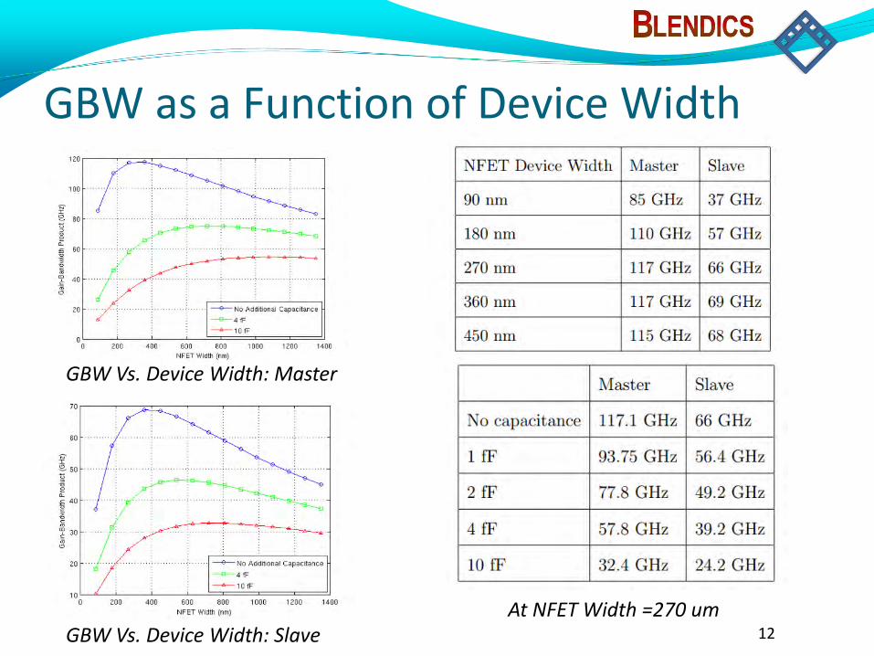
GBW as a Function of Device Width
12
GBW Vs. Device Width: Master
GBW Vs. Device Width: SlaveAt NFET Width =270 um

Physical Layout and Performance
Area: 1.73 μm x 9.6 μm, 15.65 μm2
Performance:
13
Dff, VTG(ps)
VTG(ps)
VTL(ps)
τM 19 14 10
τS 55 31 19
τeff 28 19 13
𝜏𝑒𝑓𝑓 = (𝛼
𝜏𝑚+1 − 𝛼
𝜏𝑠)−1
α is the duty cycle for the master

Summary Data and Synchronizer FFs are not the same things.
A typical data FF circuit can be converted to a good synchronizer circuit.
The method uses an AC analysis to optimize the GBW of the cascaded inverters in the critical regenerative loops.
Using low Vt devices will also improve GBW.
The benchmark synchronizer FF design is available to the public as well as MetaACE_LTD for analyzing metastability performance.
14

Questions
Where do I get the benchmark synchronizer?http://blendics.com/a-public-synchronizer/
Where do I get MetaACE_LTD?http://blendics.com/forums/
15

PVT Tolerant Synchronizer Design From equations developed through formal sensitivity
analysis the following recommendations can be made for a PVT variation tolerant design:
Use the highest supply voltage possible,
Use the lowest, available threshold transistors in regenerative loops,
Use minimum length FETs in the loops since high-field effects reduce sensitivity,
Use transistor widths no wider than necessary since wider devices can force the FETs out of strong inversion, and
If available, choose a synchronizer topology with metastable voltages that are insensitive to supply voltage changes.
16

FreePDK45 Purposely non-manufacturable 45 nm “process”
Predictive HSPICE models from ASU
PDK (Process Design Kit) from NCSU for Cadence IC6 toolset
Used by researchers to explore device performance and design flows in deep sub-micron processes
Three threshold voltages available
VTL → Low threshold → High-speed
VTG → Normal threshold → General-purpose
VTH → High threshold → Low-power17

MetaACE_LTD MetaACE_LTD is a free version of MetaACE which is a tool that
allows easy determination of parameters needed for analysis of MTBF.
Automates hundreds of simulations, tabulates results and computes τ and Tw.
Sweeps voltage and temperature for corner analysis.
Supports any circuit where SPICE circuit and transistor-level models are available.
Can be run from the command line with configuration files for inclusion into a verification/extraction flow.
Has been verified against silicon across a range of voltage and temperature. 18