Embed Size (px)
Citation preview
7/26/2019 Synchronous Machines and SC
http://slidepdf.com/reader/full/synchronous-machines-and-sc 1/6
Synchronous motors and Synchronous condenser
Abstract — This paper provides a detailed discussion of
the basic theory of operation and control of thesynchronous motor. It describes typical synchronous motor
starting and provides information regarding control and
optimization of the motor through the use of power factor
control or VAr operation that can be helpful in reducing
VAr penalties and improving voltage stability of the plant.
Typical protection is also discussed involving motor pullout
and under and overexcitation concerns
Index Terms —
I. I NTRODUCTION
A synchronous machine is a machine whose speed alternatingcurrent under steady state conditions is proportional to the re!uency
o the current in his armor. The magnetic ield created "y armature
current rotates at the same speed that creates the ield current in therotor #rotating at the synchronous speed$% and a stationary tor!ue
occurs.
As the name suggests Synchronous motors are capa"le o
running at constant speed irrespecti&e o the load acting on
them. Unli'e induction motors where speed o the motor
depends upon the tor!ue acting on them% synchronous motors
ha&e got constant speed(tor!ue characteristics.
Synchronous motors ha&e got higher eiciency #electrical to
mechanical power con&ersion ratio$ than its counterparts. Its
eiciency ranges rom )* + ),-.
A. The Working Principle: RMF – Constant
Magnetic field interaction
The constant speed characteristic is achie&ed "y interaction
"etween a constant and rotating magnetic ield. Rotor o
synchronous motor produces a constant magnetic ield and
Stator produces a Rotating magnetic ield.
1) Stator: Revolving Magnetic Field
The ield coil o stator is ecited "y a / phase AC supply. This
will produce a re&ol&ing magnetic ield # RMF $% which rotates
at synchronous speed. The way R01 is produced with / phase
AC ecitation is eplained in a separate article. R01
produced in a synchronous motor and its direction is mar'ed
in 1ig.2
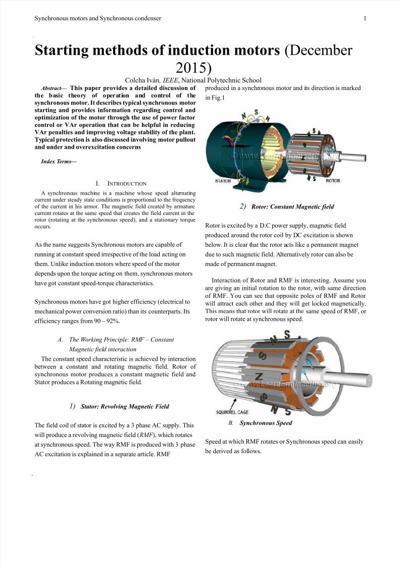
2) Rotor: Constant Magnetic field
Rotor is ecited "y a D.C power supply% magnetic ield
produced around the rotor coil "y DC ecitation is shown
"elow. It is clear that the rotor acts li'e a permanent magnet
due to such magnetic ield. Alternati&ely rotor can also "e
made o permanent magnet.
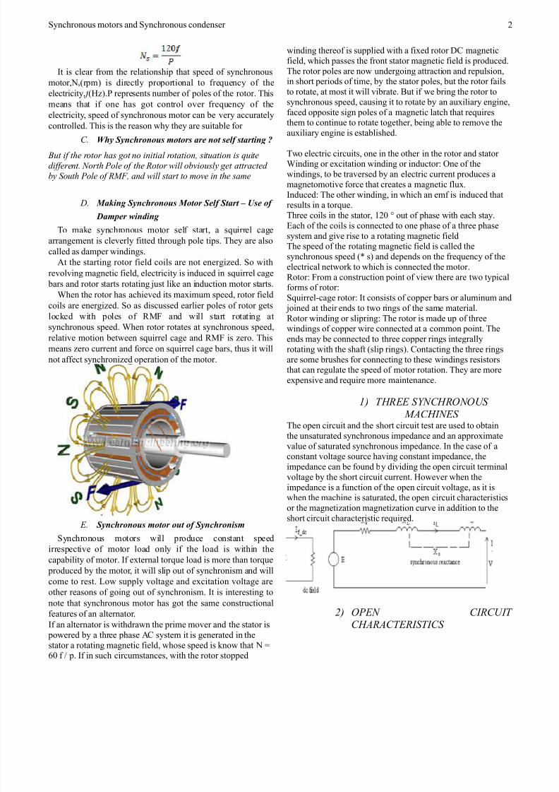
Interaction o Rotor and R01 is interesting. Assume you
are gi&ing an initial rotation to the rotor% with same direction
o R01. 3ou can see that opposite poles o R01 and Rotor will attract each other and they will get loc'ed magnetically.
This means that rotor will rotate at the same speed o R01% or
rotor will rotate at synchronous speed.
. Synchronous Speed
Speed at which R01 rotates or Synchronous speed can easily
"e deri&ed as ollows.
Starting methods of induction motors #Decem"er
,*24$Colcha I&5n ! "### % National 6olytechnic School
2
7/26/2019 Synchronous Machines and SC
http://slidepdf.com/reader/full/synchronous-machines-and-sc 2/6
Synchronous motors and Synchronous condenser
It is clear rom the relationship that speed o synchronous
motor%Ns#rpm$ is directly proportional to re!uency o the
electricity% f #78$.6 represents num"er o poles o the rotor. This
means that i one has got control o&er re!uency o the
electricity% speed o synchronous motor can "e &ery accurately
controlled. This is the reason why they are suita"le or
C. hy Synchronous motors are not self starting !
$t if the rotor has got no initial rotation! sit$ation is %$ite
different. &orth Pole of the Rotor 'ill o(io$sl* get attracted
(* +o$th Pole of RMF! and 'ill start to ,oe in the sa,e
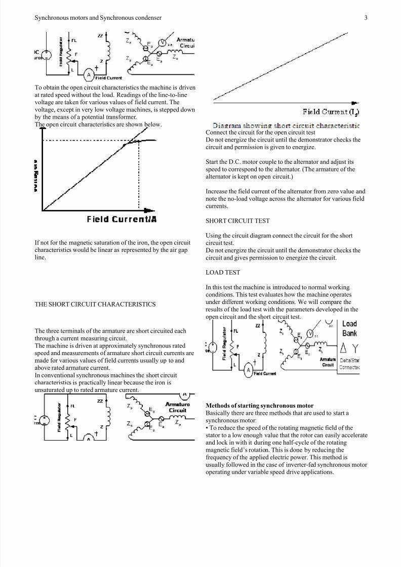
-. Ma"ing Synchronous Motor Self Start # $se of
%amper &inding
To ma'e synchronous motor sel start% a s!uirrel cage
arrangement is cle&erly itted through pole tips. They are also
called as damper windings.
At the starting rotor ield coils are not energi8ed. So with
re&ol&ing magnetic ield% electricity is induced in s!uirrel cage "ars and rotor starts rotating 9ust li'e an induction motor starts.
:hen the rotor has achie&ed its maimum speed% rotor ield
coils are energi8ed. So as discussed earlier poles o rotor gets
loc'ed with poles o R01 and will start rotating at
synchronous speed. :hen rotor rotates at synchronous speed%
relati&e motion "etween s!uirrel cage and R01 is 8ero. This
means 8ero current and orce on s!uirrel cage "ars% thus it will
not aect synchroni8ed operation o the motor.
#. Synchronous motor out of Synchronism
Synchronous motors will produce constant speed
irrespecti&e o motor load only i the load is within thecapa"ility o motor. I eternal tor!ue load is more than tor!ue
produced "y the motor% it will slip out o synchronism and will
come to rest. ;ow supply &oltage and ecitation &oltage are
other reasons o going out o synchronism. It is interesting to
note that synchronous motor has got the same constructional
eatures o an alternator.
I an alternator is withdrawn the prime mo&er and the stator is
powered "y a three phase AC system it is generated in the
stator a rotating magnetic ield% whose speed is 'now that N <=* > p. I in such circumstances% with the rotor stopped
winding thereo is supplied with a ied rotor DC magnetic
ield% which passes the ront stator magnetic ield is produced.
The rotor poles are now undergoing attraction and repulsion%in short periods o time% "y the stator poles% "ut the rotor ails
to rotate% at most it will &i"rate. ?ut i we "ring the rotor to
synchronous speed% causing it to rotate "y an auiliary engine%
aced opposite sign poles o a magnetic latch that re!uiresthem to continue to rotate together% "eing a"le to remo&e the
auiliary engine is esta"lished.
Two electric circuits% one in the other in the rotor and stator :inding or ecitation winding or inductor@ One o the
windings% to "e tra&ersed "y an electric current produces a
magnetomoti&e orce that creates a magnetic lu.
Induced@ The other winding% in which an em is induced thatresults in a tor!ue.
Three coils in the stator% 2,* out o phase with each stay.
Bach o the coils is connected to one phase o a three phase
system and gi&e rise to a rotating magnetic ieldThe speed o the rotating magnetic ield is called the
synchronous speed # s$ and depends on the re!uency o the
electrical networ' to which is connected the motor.
Rotor@ 1rom a construction point o &iew there are two typicalorms o rotor@
S!uirrel(cage rotor@ It consists o copper "ars or aluminum and
9oined at their ends to two rings o the same material.
Rotor winding or slipring@ The rotor is made up o threewindings o copper wire connected at a common point. The
ends may "e connected to three copper rings integrally
rotating with the shat #slip rings$. Contacting the three rings
are some "rushes or connecting to these windings resistorsthat can regulate the speed o motor rotation. They are more
epensi&e and re!uire more maintenance.
1) TR## +/&CR0&0+
MAC"&#+ The open circuit and the short circuit test are used to o"tain
the unsaturated synchronous impedance and an approimate
&alue o saturated synchronous impedance. In the case o aconstant &oltage source ha&ing constant impedance% the
impedance can "e ound "y di&iding the open circuit terminal
&oltage "y the short circuit current. 7owe&er when the
impedance is a unction o the open circuit &oltage% as it iswhen the machine is saturated% the open circuit characteristics
or the magneti8ation magneti8ation cur&e in addition to the
short circuit characteristic re!uired.
2) 0P#& C"RC"T CARACT#R"+T"C+
,
7/26/2019 Synchronous Machines and SC
http://slidepdf.com/reader/full/synchronous-machines-and-sc 3/6
Synchronous motors and Synchronous condenser
To o"tain the open circuit characteristics the machine is dri&en
at rated speed without the load. Readings o the line(to(line&oltage are ta'en or &arious &alues o ield current. The
&oltage% ecept in &ery low &oltage machines% is stepped down
"y the means o a potential transormer.
The open circuit characteristics are shown "elow.
I not or the magnetic saturation o the iron% the open circuitcharacteristics would "e linear as represented "y the air gap
line.
T7B S7ORT CIRCUIT C7ARACTBRISTICS
The three terminals o the armature are short circuited each
through a current measuring circuit.
The machine is dri&en at approimately synchronous ratedspeed and measurements o armature short circuit currents are
made or &arious &alues o ield currents usually up to and
a"o&e rated armature current.
In con&entional synchronous machines the short circuitcharacteristics is practically linear "ecause the iron is
unsaturated up to rated armature current.
Connect the circuit or the open circuit test
Do not energi8e the circuit until the demonstrator chec's thecircuit and permission is gi&en to energi8e.
Start the D.C. motor couple to the alternator and ad9ust its
speed to correspond to the alternator. #The armature o thealternator is 'ept on open circuit.$
Increase the ield current o the alternator rom 8ero &alue and
note the no(load &oltage across the alternator or &arious ieldcurrents.
S7ORT CIRCUIT TBST
Using the circuit diagram connect the circuit or the short
circuit test.
Do not energi8e the circuit until the demonstrator chec's the
circuit and gi&es permission to energi8e the circuit.
;OAD TBST
In this test the machine is introduced to normal wor'ing
conditions. This test e&aluates how the machine operatesunder dierent wor'ing conditions. :e will compare the
results o the load test with the parameters de&eloped in the
open circuit and the short circuit test.
ethods of starting synchronous motor
?asically there are three methods that are used to start a
synchronous motor@
To reduce the speed o the rotating magnetic ield o the
stator to a low enough &alue that the rotor can easily accelerateand loc' in with it during one hal(cycle o the rotating
magnetic ieldEs rotation. This is done "y reducing the
re!uency o the applied electric power. This method is
usually ollowed in the case o in&erter(ed synchronous motor operating under &aria"le speed dri&e applications.
/

7/26/2019 Synchronous Machines and SC
http://slidepdf.com/reader/full/synchronous-machines-and-sc 4/6
Synchronous motors and Synchronous condenser
To use an eternal prime mo&er to accelerate the rotor o
synchronous motor near to its synchronous speed and then
supply the rotor as well as stator. O course care should "eta'en to ensure that the direction o rotation o the rotor as
well as that o the rotating magnetic ield o the stator are the
same. This method is usually ollowed in the la"oratory( the
synchronous machine is started as a generator and is thenconnected to the supply mains "y ollowing the
synchroni8ation or paralleling procedure. Then the powersupply to the prime mo&er is disconnected so that the
synchronous machine will continue to operate as a motor. To use damper windings or amortisseur windings i these are
pro&ided in the machine. The damper windings or amortisseur
windings are pro&ided in most o the large synchronous
motors in order to nulliy the oscillations o the rotorwhene&er the synchronous machine is su"9ected to a
periodically &arying load. Bach o these methods o starting a
synchronous motor are descri"ed "elow in detail.
otor Starting by !educing the supply "re#uency
I the rotating magnetic ield o the stator in a synchronous
motor rotates at a low enough speed% there will "e no pro"lem
or the rotor to accelerate and to loc' in with the statorEsmagnetic ield. The speed o the stator magnetic ield can then
"e increased to its rated operating speed "y gradually
increasing the supply re!uency up to its normal 4*( or =*(
78 &alue. This approach to starting o synchronous motorsma'es a lot o sense% "ut there is a "ig pro"lem@ :here rom
can we get the &aria"le re!uency supplyF The usual power
supply systems generally regulate the re!uency to "e 4* or =*
78 as the case may "e. 7owe&er% &aria"le(re!uency &oltagesource can "e o"tained rom a dedicated generator only in the
olden days and such a situation was o"&iously impractical
ecept or &ery unusual or special dri&e applications. ?ut the
present day solid state power con&erters oer an easy solution
to this. :e now ha&e the rectiier( in&erter andcyclocon&erters% which can "e used to con&ert a constant
re!uency AC supply to a &aria"le re!uency AC supply. :ith
the de&elopment o such modern solid(state &aria"le(re!uency dri&e pac'ages% it is thus possi"le to continuously
control the re!uency o the supply connected to the
synchronous motor all the way rom a raction o a hert8 up to
and e&en a"o&e the normal rated re!uency. I such a &aria"le(re!uency dri&e unit is included in a motor(control circuit to
achie&e speed control% then starting the synchronous motor is
&ery easy(simply ad9ust the re!uency to a &ery low &alue or
starting% and then raise it up to the desired operating re!uencyor normal running. :hen a synchronous motor is operated at
a speed lower than the rated speed% its internal generated&oltage #usually called the counter B01$ BA < GH will "e
smaller than normal. As such the terminal &oltage applied tothe motor must "e reduced proportionally with the re!uency
in order to 'eep the stator current within the rated &alue.
Jenerally% the &oltage in any &aria"le(re!uency power supply
&aries roughly linearly with the output re!uency.
otor Starting with an $xternal otor
The second method o starting a synchronous motor is to
attach an eternal starting motor #pony motor$ to it and "ringthe synchronous machine to near a"out its rated speed #"ut not
eactly e!ual to it% as the synchroni8ation process may ail to
indicate the point o closure o the main switch connecting the
synchronous machine to the supply system$ with the ponymotor. Then the output o the synchronous machine can "e
synchronised or paralleled with its power supply system as a
generator% and the pony motor can "e detached rom the shat
o the machine or the supply to the pony motor can "edisconnected. Once the pony motor is turned O11% the shat o
the machine slows down% the speed o the rotor magnetic ield?R alls "ehind ?net% momentarily and the synchronous
machine continues to operate as a motor. As soon as it "eginsto operates as a motor the synchronous motor can "e loaded in
the usual manner 9ust li'e any motor. This whole procedure is
not as cum"ersome as it sounds% since many synchronous
motors are parts o motor(generator sets% and the synchronousmachine in the motor(generator set may "e started with the
other machine ser&ing as the starting motor. 0ore o&er% the
starting motor is re!uired to o&ercome only the mechanical
inertia o the synchronous machine without any mechanicalload # load is attached only ater the synchronous machine is
paralleled to the power supply system$. Since only the motorEs
inertia must "e o&ercome% the starting motor can ha&e a much
smaller rating than the synchronous motor it is going to start.Jenerally most o the large synchronous motors ha&e
"rushless ecitation systems mounted on their shats. It is then
possi"le to use these eciters as the starting motors. 1or many
medium(si8e to large synchronous motors% an eternal startingmotor or starting "y using the eciter may "e the only possi"le
solution% "ecause the power systems they are tied to may not
"e a"le to handle the starting currents needed to use the
damper #amortisseur$ winding approach descri"ed net.
otor Starting by %sing damper &Amortisseur' (inding
As already mentioned earlier most o the large synchronous
motors are pro&ided with damper windings% in order to nulliy
the oscillations o the rotor whene&er the synchronousmachine is su"9ected to a periodically &arying load. Damper
windings are special "ars laid into slots cut in the pole ace o
a synchronous machine and then shorted out on each end "y alarge shorting ring% similar to the s!uirrel cage rotor "ars. A
pole ace with a set o damper windings is shown in 1igure..
:hen the stator o such a synchronous machine is connected
to the /(6hase AC supply% the machine starts as a /(6haseinduction machine due to the presence o the damper "ars% 9ust
li'e a s!uirrel cage induction motor. Kust as in the case o a /(
6hase s!uirrel cage induction motor% the applied &oltage must
"e suita"ly reduced so as to limit the starting current to thesae rated &alue. Once the motor pic's up to a speed near
a"out its synchronous speed% the DC supply to its ieldwinding is connected and the synchronous motor pulls into
step i.e. it continues to operate as a Synchronous motorrunning at its synchronous speed.
)ehavior of a synchronous motor
The "eha&ior o a synchronous motor can "e predicted "yconsidering its e!ui&alent circuit on similar lines to that o a
synchronous generator as descri"ed "elow.
L
7/26/2019 Synchronous Machines and SC
http://slidepdf.com/reader/full/synchronous-machines-and-sc 5/6
Synchronous motors and Synchronous condenser
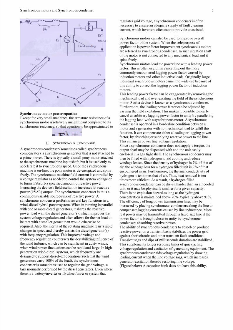
Synchronous*motor power e#uationBcept or &ery small machines% the armature resistance o asynchronous motor is relati&ely insigniicant compared to its
synchronous reactance% so that e!uation to "e approimated to
II. S3NC7RONOUS CONDBNSBR
A synchronous condenser #sometimes called synchronouscompensator$ is a synchronous generator that is not attached to
a prime mo&er. There is typically a small pony motor attached
to the synchronous machine input shat% "ut it is used only to
accelerate it to synchronous speed. Once the synchronous
machine is on(line% the pony motor is de(energi8ed and spinsreely. The synchronous machine ield current is controlled "y
a &oltage regulator as needed to control the system &oltage or
to urnish>a"sor" a speciied amount o reacti&e power.Increasing the de&iceMs ield ecitation increases its reacti&e
power #'AR$ output. The synchronous condenser is thus a
continuous &aria"le source>sin' o reacti&e power. A
synchronous condenser perorms se&eral 'ey unctions in awind(diesel hy"rid power system. :hen in running in parallel
with one or more diesel generators% it shares the reacti&e
power load with the diesel generator#s$% which impro&es the
system &oltage regulation and oten allows or the net load to "e met with a smaller genset than would otherwise "e
re!uired. Also% the inertia o the rotating machine resists rapidchanges in speed and there"y assists the diesel generator#s$
with re!uency regulation. This impro&ed &oltage andre!uency regulation counteracts the desta"ili8ing inluence o
the wind tur"ines% which can "e signiicant in gusty winds%
when wind power luctuations can "e rapid and large. In high
penetration wind(diesel systems% which re!uently aredesigned to support diesel(o operation #such that the wind
generators carry 2**- o the load$% the synchronous
condenser is sometimes used to regulate the grid &oltage% a
tas' normally perormed "y the diesel generators. B&en wherethere is a "attery>in&erter or lywheel>in&erter system that
regulates grid &oltage% a synchronous condenser is oten
necessary to ensure an ade!uate supply o ault clearing
current% which in&erters oten cannot pro&ide unassisted.
Synchronous motors can also "e used to impro&e o&erall
power actor o the system. :hen the sole purpose o
application is power actor impro&ement synchronous motorsare reerred as synchronous condenser. In such situation shat
o the motor is not connected to any mechanical load and itspins reely.
Synchronous motors load the power line with a leading poweractor. This is oten useull in cancelling out the more
commonly encountered lagging power actor caused "y
induction motors and other inducti&e loads. Originally% large
industrial synchronous motors came into wide use "ecause othis a"ility to correct the lagging power actor o induction
motors.
This leading power actor can "e eaggerated "y remo&ing the
mechanical load and o&er eciting the ield o the synchronousmotor. Such a de&ice is 'nown as a synchronous condenser.
1urthermore% the leading power actor can "e ad9usted "y
&arying the ield ecitation. This ma'es it possi"le to nearly
cancel an ar"itrary lagging power actor to unity "y parallelingthe lagging load with a synchronous motor. A synchronous
condenser is operated in a "orderline condition "etween a
motor and a generator with no mechanical load to ulill this
unction. It can compensate either a leading or lagging poweractor% "y a"sor"ing or supplying reacti&e power to the line.
This enhances power line &oltage regulation.
Since a synchronous condenser does not supply a tor!ue% the
output shat may "e dispensed with and the unit easilyenclosed in a gas tight shell. The synchronous condenser may
then "e illed with hydrogen to aid cooling and reduce
windage losses. Since the density o hydrogen is - o that o
air% the windage loss or a hydrogen illed unit is - o that
encountered in air. 1urthermore% the thermal conducti&ity ohydrogen is ten times that o air. Thus% heat remo&al is ten
times more eicient. As a result% a hydrogen illed
synchronous condenser can "e dri&en harder than an air cooledunit% or it may "e physically smaller or a gi&en capacity.
There is no eplosion ha8ard as long as the hydrogen
concentration is maintained a"o&e *-% typically a"o&e )2-.
The eiciency o long power transmission lines may "eincreased "y placing synchronous condensers along the line to
compensate lagging currents caused "y line inductance. 0ore
real power may "e transmitted through a ied si8e line i the
power actor is "rought closer to unity "y synchronouscondensers a"sor"ing reacti&e power.
The a"ility o synchronous condensers to a"sor" or producereacti&e power on a transient "asis sta"ili8es the power grid
against short circuits and other transient ault conditions.Transient sags and dips o milliseconds duration are sta"ili8ed.
This supplements longer response times o !uic' acting
&oltage regulation and ecitation o generating e!uipment. The
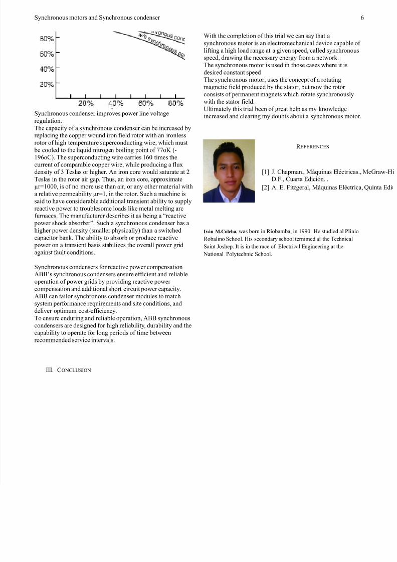
synchronous condenser aids &oltage regulation "y drawingleading current when the line &oltage sags% which increases
generator ecitation there"y restoring line &oltage.
#1igure "elow$ A capacitor "an' does not ha&e this a"ility.
4
7/26/2019 Synchronous Machines and SC
http://slidepdf.com/reader/full/synchronous-machines-and-sc 6/6
Synchronous motors and Synchronous condenser
Synchronous condenser impro&es power line &oltage
regulation.
The capacity o a synchronous condenser can "e increased "yreplacing the copper wound iron ield rotor with an ironless
rotor o high temperature superconducting wire% which must
"e cooled to the li!uid nitrogen "oiling point o oG #(
2)=oC$. The superconducting wire carries 2=* times thecurrent o compara"le copper wire% while producing a lu
density o / Teslas or higher. An iron core would saturate at ,
Teslas in the rotor air gap. Thus% an iron core% approimatePr<2***% is o no more use than air% or any other material with
a relati&e permea"ility Pr<2% in the rotor. Such a machine issaid to ha&e considera"le additional transient a"ility to supply
reacti&e power to trou"lesome loads li'e metal melting arcurnaces. The manuacturer descri"es it as "eing a Qreacti&e
power shoc' a"sor"er. Such a synchronous condenser has a
higher power density #smaller physically$ than a switched
capacitor "an'. The a"ility to a"sor" or produce reacti&e power on a transient "asis sta"ili8es the o&erall power grid
against ault conditions.
Synchronous condensers or reacti&e power compensationA??Es synchronous condensers ensure eicient and relia"le
operation o power grids "y pro&iding reacti&e power
compensation and additional short circuit power capacity.A?? can tailor synchronous condenser modules to matchsystem perormance re!uirements and site conditions% and
deli&er optimum cost(eiciency.
To ensure enduring and relia"le operation% A?? synchronous
condensers are designed or high relia"ility% dura"ility and thecapa"ility to operate or long periods o time "etween
recommended ser&ice inter&als.
III. CONC;USION
:ith the completion o this trial we can say that a
synchronous motor is an electromechanical de&ice capa"le o
liting a high load range at a gi&en speed% called synchronousspeed% drawing the necessary energy rom a networ'.
The synchronous motor is used in those cases where it is
desired constant speed
The synchronous motor% uses the concept o a rotatingmagnetic ield produced "y the stator% "ut now the rotor
consists o permanent magnets which rotate synchronouslywith the stator ield.
Ultimately this trial "een o great help as my 'nowledgeincreased and clearing my dou"ts a"out a synchronous motor.
R B1BRBNCBS
2 K. Chapman.% 05!uinas Blctricas.% 0D.1.% Cuarta BdiciVn. .
, A. B. 1it8geral% 05!uinas Blctrica% W
Iv+n .,olcha- was "orn in Rio"am"a% in 2))*. 7e studied al 6linio
Ro"alino School. 7is secondary school ternimed al the Technical
Saint Koshep. It is in the race o Blectrical Bngineering at the
National 6olytechnic School.
=