Embed Size (px)
Citation preview

ET100A [ver2] Synchronous WAN Ethernet Bridge 10/100Base-TX Ethernet over V.35, X.21, RS-232/530/449


CTC Union Technologies Co., Ltd. Neihu Technology Park
Vienna Technology Center
8F, No. 60 Zhouzi St.
Neihu, Taipei, 114
Taiwan
ET100A Ethernet WAN Bridge, User Manual
Version 2.0 March 21, 2014 Release
This manual supports the following models:
ET100A Ethernet WAN Bridge
(manufactured after March 2014)
All specifications subject to change without notice.


Table of Contents
i
OVERVIEW........................................................................................................ 7
FEATURES ......................................................................................................... 7
SPECIFICATIONS................................................................................................ 8
THEORY OF OPERATION .................................................................................. 13
DIP SWITCH SETTING TABLES:.......................................................................... 16
WAN PORT PIN ASSIGNMENT.......................................................................... 20
CABLE PIN ASSIGNMENTS: .............................................................................. 24
RS‐530 CABLE, 25 CONDUCTOR ROUND, 1 TO 1, 1M....................................................24
V.35 CABLE, MULTI‐CONDUCTOR ROUND, 1M..............................................................25
RS‐449 CABLES, MULTI‐CONDUCTOR ROUND, 1M........................................................26
X.21 CABLES, MULTI‐CONDUCTOR ROUND, 1M............................................................27
APPLICATION EXAMPLES................................................................................. 28

Table of Contents
ii
This page left blank intentionally.

ET100A LAN-WAN Bridge
7
Overview The ET100A Network Bridge is a high performance, remote,
self‐learning Ethernet bridge. Its compact size and low cost make it ideal
for cost‐sensitive bridging applications, or as a LAN extender or segmenter
over bit stream type infrastructures. Several selectable synchronous data
interfaces, including V.35, RS‐530, RS‐449, X.21, and RS‐232, make this
Ethernet Bridge's connection between 10Base‐T and 100Base‐TX LAN and
various SYNC data port interfaces convenient.
Features Supports raw HDLC, Cisco® HDLC, and PPP encapsulation
10BASE-T/100BASE-TX, Full Duplex or Half Duplex
HP Auto-MDI/MDIX detects and corrects crossed cable
Automatic address learning, aging and deletion after 5 minutes
Forwarding and filtering rate at wire speed with through put latency of
1 frame.
Auto padding of undersized packets to meet the minimum Ethernet
packet size requirement
1763 packet buffer
Ethernet interface has automatic Twisted Pair polarity correction
Built-in nx64K / nx56K timing clock generator for WAN link for speeds
up to 10mbps
256 MAC Table
Ethernet flow control per IEEE802.3x
ET100A LAN-WAN Bridge
8
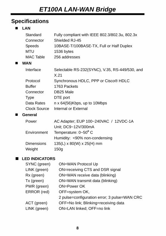
Specifications LAN
Standard Fully compliant with IEEE 802.3/802.3u, 802.3x Connector Shielded RJ-45 Speeds 10BASE-T/100BASE-TX, Full or Half Duplex MTU 1536 bytes MAC Table 256 addresses
WAN Interface Selectable RS-232(SYNC), V.35, RS-449/530, and X.21 Protocol Synchronous HDLC, PPP or Cisco® HDLC Buffer 1763 Packets Connector DB25 Male Type DTE port Data Rates n x 64(56)Kbps, up to 10Mbps Clock Source Internal or External
General Power AC Adapter; EUP 100~240VAC / 12VDC-1A Unit; DC9~12V/300mA Environment Temperature: 0~50o C Humidity: <90% non-condensing Dimensions 135(L) x 80(W) x 25(H) mm Weight 150g
LED INDICATORS SYNC (green) ON=WAN Protocol Up LINK (green) ON=receiving CTS and DSR signal Rx (green) ON=WAN receive data (blinking) Tx (green) ON=WAN transmit data (blinking) PWR (green) ON=Power OK ERROR (red) OFF=system OK, 2 pulse=configuration error; 3 pulse=WAN CRC ACT (green) OFF=No link; Blinking=receiving data LINK (green) ON=LAN linked; OFF=no link

ET100A LAN-WAN Bridge
9
Clock Generator SYNC
SPEED
N56K to 1792K
N64K to
10M
InterfaceSelect
RS-530/449Serial Port
Line Drivers
Figure 1: ET100A Functional Block Diagram
V.35 X.21
RS-232
SYNC HDLC
CONTROLLER
Full DuplexHalf Duplex
Ext. clock Int. clock
FILTER ENGINE
MAC Address Table
Frame Buffer
WAN SIDEDB25-Male
DTE
LAN SIDERJ-45
ERROR
ClockSource
LINKTx LED Rx LED SYNC
ACT
LINK IEEE802.3u I/F

ET100A LAN-WAN Bridge Unit Detail
13
11 10
8
6
7
9
5
12
4 2
3
1
Figure 2. ET100A Unit Detail
10

ET100A LAN-WAN Bridge
11
(1) DB25 Male Connector:
This connector connects to the appropriate adapter cable for
connection to the various supported data interfaces. The ET100A
performs in DTE mode and its WAN port connector may be
connected directly to a DCE device (such as a modem or DSU/CSU).
(2) SYNC LED:
Green, where ON indicates protocol is up. If OFF, first make sure
physical link is up, then make sure protocol settings match.
(3) LINK LED:
Green, where ON indicates the presence of CTS / DSR signal on WAN
connection.
(4) RX LED:
Green, on or flashing indicates receiving data on the WAN interface.
(5) TX LED:
Green, on or flashing indicates transmitting data on the WAN
interface.
(6) SW1:
Configuration setting for the bridge. (Please refer to DIP SW setting
table.)
(7) SW2:
Configuration setting for the bridge. (Please refer to DIP SW setting
table.)
(8) RJ‐45 Ethernet LAN Port:
This is an auto‐MDI/MDIX port for connection to the LAN.

ET100A LAN-WAN Bridge
12
(9) LINK LED: (LAN)
Green, indicates the Ethernet has a link to an external device.
(10) ACT LED: (LAN)
Green, indicates data being received from the LAN connection.
(11) ERROR LED:
Red, indicates an error condition as follows:
ON ‐ System Error
Pulse 2 ‐ Configuration error
Pulse 3 ‐ WAN receive has CRC errors
(12) PWR LED:
Green on, when external power adapter is plugged in and AC power
is supplied to it.
(13) DC 9~12V
This jack receives power from the external DC 12V AC power
switching adapter. The center pin is positive voltage.

ET100A LAN-WAN Bridge
13
Theory of Operation
A bridge is used to connect networks locally or remotely such that
they appear to the user to be the same network. An Ethernet LAN bridge
will connect two LAN segments at the Data Link Layer (ISO Layer 2). At this
layer, the MAC (Media Access Control) addresses, are used for low level
addressing to send information to devices. The bridge builds tables of MAC
addresses for each network segment based on the source and destination
addresses of the packets it receives and forwards, then filters the traffic
not destined for the remote network.
The Ethernet‐WAN bridge will connect two remote Ethernet
networks over bit stream interfaces such as that of synchronous modems
or DSU/CSUs. One method to do this is to use HDLC, an international
standard set by the ISO, a set of protocols for carrying data over a link with
error and flow control. Another method uses PPP and a third uses Cisco®
HDLC.
The ET100A utilizes both Ethernet Bridging and encapsulation to
provide a connection between LANs over bit stream architectures. The
LAN side of the ET100A receives an Ethernet packet and examines its
destination MAC address. If it knows the MAC is on the local network then
it simply drops the packet. Otherwise, if it knows the packet destination is
on the remote side, or if it cannot be determined because its MAC cannot
be found in the table, then it forwards it. During forwarding, the packet is
processed for transmission across the WAN link. Here is where the
Ethernet packet in encapsulated.

ET100A LAN-WAN Bridge When the HDLC or PPP packet is received on the remote side unit's
data port, the packet is checked for transmission errors, then the original
Ethernet packet(s) is recovered and sent out the remote's LAN port
completing the transmission. Here is the typical application of the
ET100A.
ET100A/V35 ET100A/V35
Figure 3. Typical application of ET100A LAN‐WAN Bridge.
Many times the ET100A is commonly referred to as an Ethernet to
V.35, Ethernet to X.21, or Ethernet to Datacom 'converter'. As a
sales/marketing term or non‐technical reference, the term is OK. However,
from a technical standpoint, the term is a misnomer. The Ethernet is not
"converted" to V.35, it is run "over" the V.35 link. Conversion also implies
that the interface can work both ways. This is NOT the case for the
LAN‐WAN Bridge as the following application shows.
ET100A/V35 ET100A/V35
Figure 4. Application NOT ALLOWED for ET100A.
14

ET100A LAN-WAN Bridge
15
Why does the previous application not work? It won't work because
the application requires a bit stream to be encapsulated into Ethernet
packets, or into TCP/IP and then Ethernet, for transmission across the LAN.
This requires more than just manipulation at the Data Link layer (ISO Layer
2), it requires programming to include all seven layers including the
Application layer. Transmitting bit stream or TDM (time division
multiplexed) data over Ethernet requires a device such as an
IP‐Multiplexer.
Please refer to the "Applications" section at the end of this manual
for additional application examples.

ET100A LAN-WAN Bridge
16
DIP Switch Setting Tables:
SW1-1 SW1-2 FUNCTION REMARK OFF ON HDLC ON OFF Cisco® HDLC OFF OFF PPP
Table 1: Encapsulation Protocol Setting
DIP SW1 STATE FUNCTION REMARK
OFF WAN CLK: External -3 ON WAN CLK: Internal
Table 2: Clock Source Setting
DIP SW1 STATE FUNCTION REMARK
OFF CTS/DSR -4 ON Active DCD always on
Table 3: DCD Handshaking Setting
DIP SW1 STATE FUNCTION REMARK
OFF Enable 802.3x -5 ON Disable
Table 4: LAN Flow Control Settings
SW1-6 SW1-7 SW1-8 Function REMARK OFF X X Auto SW1-7,1-8 don't care ON OFF OFF 100/Full ON OFF ON 100/Half
ON ON OFF 10/Full ON ON ON 10/Half
Table 5: LAN Interface Setting
SW2-1 SW2-2 TYPE OFF OFF V.35 ON OFF X.21/RS-530/RS-449 ON ON RS-232
Table 6: WAN Interface Type Setting

ET100A LAN-WAN Bridge
17
When the ET100A is set to internal WAN clock, SW2‐3 to SW2‐9
provision the data rate. If WAN clock is set external, these are ignored.
SW2-3 SW2-4 SW2-5 SW2-6 SW2-7 SW2-8 OFF SW2-8 ON SW2-8 OFF SW2-8 ON
SW2-9 OFFN*64K
SW2-9 OFFN*56K
SW2-9 ON HS-1
SW2-9 ON HS-2
OFF OFF OFF OFF OFF 64K 56K 2176K 6272K ON OFF OFF OFF OFF 128K 112K 2304K 6400K OFF ON OFF OFF OFF 192K 168K 2432K 6528K ON ON OFF OFF OFF 256K 224K 2560K 6656K OFF OFF ON OFF OFF 320K 280K 2688K 6784K ON OFF ON OFF OFF 384K 336K 2816K 6912K OFF ON ON OFF OFF 448K 392K 2944K 7040K ON ON ON OFF OFF 512K 448K 3072K 7168K OFF OFF OFF ON OFF 576K 504K 3200K 7296K ON OFF OFF ON OFF 640K 560K 3328K 7424K OFF ON OFF ON OFF 704K 616K 3456K 7552K ON ON OFF ON OFF 768K 672K 3584K 7680K OFF OFF ON ON OFF 832K 728K 3712K 7808K ON OFF ON ON OFF 896K 784K 3840K 7936K OFF ON ON ON OFF 960K 840K 3968K 8064K ON ON ON ON OFF 1024K 896K 4096K 8192K OFF OFF OFF OFF ON 1088K 952K 4224K 8320K ON OFF OFF OFF ON 1152K 1008K 4352K 8448K OFF ON OFF OFF ON 1216K 1064K 4480K 8576K ON ON OFF OFF ON 1280K 1120K 4608K 8704K OFF OFF ON OFF ON 1344K 1176K 4736K 8832K ON OFF ON OFF ON 1408K 1232K 4864K 8960K OFF ON ON OFF ON 1472K 1288K 4992K 9088K ON ON ON OFF ON 1536K 1344K 5120K 9216K OFF OFF OFF ON ON 1600K 1400K 5248K 9344K ON OFF OFF ON ON 1664K 1456K 5376K 9472K OFF ON OFF ON ON 1728K 1512K 5504K 9600K ON ON OFF ON ON 1792K 1568K 5632K 9728K OFF OFF ON ON ON 1856K 1624K 5760K 9856K ON OFF ON ON ON 1920K 1680K 5888K 9984K OFF ON ON ON ON 1984K 1736K 6016K 10112K ON ON ON ON ON 2048K 1792K 6144K 10240K
Table 7: Data Rate Settings

ET100A LAN-WAN Bridge
18
When the ET100A leaves the factory, all DIP switch settings are set
to the OFF position.
Auto‐negotiation:
When this feature is enabled (SW1‐6=OFF), the Speed (SW1‐7) and
Duplex (SW1‐8) settings are ignored and are automatically determined
from the LAN connection. When this feature is disabled (SW1‐6=ON), the
Duplex and Speed settings of the LAN follow the settings of SW1‐7 and
SW1‐8. Use forced mode with caution to avoid Duplex Mismatch.
Protocol Selection:
The ET100A supports selecting one of three encapsulation protocols.
When selecting HDLC, the encapsulation is per ISO 13239. The cHDLC
encapsulation is compatible with Cisco® modified HDLC. The PPP
encapsulation follows RFC1661 and is also a very popular encapsulation
protocol. The protocol selection is controlled by the setting of DIP switches
SW1‐1 and SW1‐2.
Clock Selection:
The ET100A inherently acts as a DTE device. A 1:1 cable is used to
connect to a DCE device such as a modem, CSU/DSU or data multiplexer.
Clock source comes from the DCE so the clock setting is usually external
(SW1‐4 OFF). The ET100A is also capable of acting as a DCE. In this case a
crossover cable is required and clock setting (SW1‐4 ON) is internal. Data
rate is then set by SW2, 3~9 and ET100A provides clock source.

ET100A LAN-WAN Bridge
19
LAN Flow Control:
The ET100A LAN port supports IEEE802.3x flow control, which can
help to regulate the higher speed LAN traffic that hits the bottle neck of
the slower WAN speed. Without flow control, the LAN packets that exceed
the WAN speed will be dropped and the resulting timeout caused must be
handled by the application layer.
LAN Auto Negotiation:
The ET100A LAN port supports auto‐negotiation per IEEE802.3u.
When auto negotiation is enabled and the LAN port connects to another
auto negotiation compliant port, the LAN speed will be auto detected
while the Duplex should be negotiated to Full Duplex.
When connecting to legacy equipment, it may be necessary to 'force'
the speed and Duplex on the LAN port. Care must be taken here to avoid a
Duplex Mismatch condition when a 'forced' port connects to an 'auto' port.
Without negotiation, an 'auto' port will revert to Half Duplex per the
IEEE802.3u standard. A Duplex Mismatch condition could result in
extremely poor network performance.
WAN Interface Selection:
The ET100A has selectable hardware interface circuits. When set to
X.21/RS‐530/RS‐449, the logic, clock and handshaking signals all follow
RS‐422 electrical (balanced signals). When set to RS‐232, all signals
become single ended and follow RS‐232D signal levels. When configured as
V.35, the logic and clock signals follow RS‐422 electrical, while handshaking
signals are RS‐232 electrical.
ET100A LAN-WAN Bridge
20
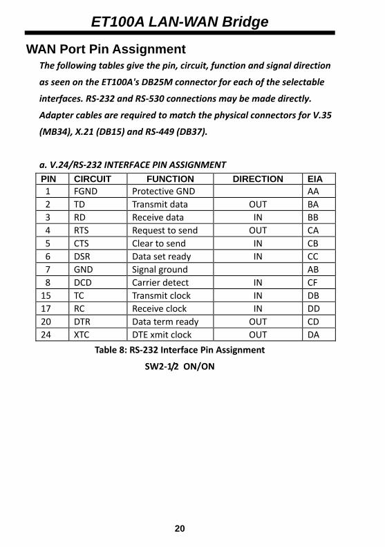
WAN Port Pin Assignment The following tables give the pin, circuit, function and signal direction
as seen on the ET100A's DB25M connector for each of the selectable
interfaces. RS‐232 and RS‐530 connections may be made directly.
Adapter cables are required to match the physical connectors for V.35
(MB34), X.21 (DB15) and RS‐449 (DB37).
a. V.24/RS‐232 INTERFACE PIN ASSIGNMENT PIN CIRCUIT FUNCTION DIRECTION EIA 1 FGND Protective GND AA 2 TD Transmit data OUT BA 3 RD Receive data IN BB 4 RTS Request to send OUT CA 5 CTS Clear to send IN CB 6 DSR Data set ready IN CC 7 GND Signal ground AB 8 DCD Carrier detect IN CF 15 TC Transmit clock IN DB 17 RC Receive clock IN DD 20 DTR Data term ready OUT CD 24 XTC DTE xmit clock OUT DA
Table 8: RS‐232 Interface Pin Assignment
SW2‐1/2 ON/ON

ET100A LAN-WAN Bridge
21
b. V.35 INTERFACE PIN ASSIGNMENT PIN CIRCUIT FUNCTION DIRECTION CCITT 1 FGND Protective GND 101 2 TD(A) Xmit data A OUT 103 3 RD(A) Receive data A IN 104 4 RTS Request to send OUT 105 5 CTS Clear to send IN 106 6 DSR Data set ready IN 107 7 GND Signal ground 102 8 DCD Data carrier detect IN 109 9 RC(B) Receive clock B IN 115 11 XTC(B) DTE Xmit clock B OUT 113 12 TC(B) Xmit clock B IN 114 14 TD(B) Xmit data B OUT 103 15 TC(A) Xmit clock A IN 114 16 RD(B) Receive data B IN 104 17 RC(A) Receive clock A IN 115 20 DTR Data terminal ready OUT 108 24 XTC(A) DTE Xmit clock A OUT 113
Table 9: V.35 Interface Pin Assignment
SW2‐1/2 OFF/OFF

ET100A LAN-WAN Bridge
22
c. RS‐449/RS‐530 INTERFACE PIN ASSIGNMENT PIN CIRCUIT FUNCTION DIRECTION CCITT 1 FGND Protective GND 101 2 SD(A) Xmit data A OUT 103 3 RD(A) Receive data A IN 104 4 RS(A) Request to send A OUT 105 5 CS(A) Clear to send A IN 106 6 DM(A) Data set ready A IN 107 7 GND Signal ground 102 8 RR(A) Data carrier detect A IN 109 9 RT(B) Receive clock B IN 115 10 RR(B) Data carrier detect B IN 109 11 TT(B) DTE Xmit clock B OUT 113 12 ST(B) Xmit clock B IN 114 13 CS(B) Clear to send B IN 106 14 SD(B) Xmit data B OUT 103 15 ST(A) Xmit clock A IN 114 16 RD(B) Receive data B IN 104 17 RT(A) Receive clock A IN 115 19 RS(B) Request to send B OUT 105 20 TR(A) Data terminal ready A OUT 108 22 DM(B) Data set ready B IN 107 23 TR(B) Data terminal ready B OUT 108 24 TT(A) DTE Xmit clock A OUT 113
Table 10: RS‐449/RS‐530 INTERFACE PIN ASSIGNMENT
SW2‐1/2 ON/OFF

ET100A LAN-WAN Bridge
23
d. X.21 INTERFACE PIN ASSIGNMENT PIN CIRCUIT FUNCTION DIRECTION CCITT 1 FGND Protective GND 101 2 T(A) Xmit data A OUT 103 3 R(A) Receive data A IN 104 4 C(A) Request to send A OUT 105 7 GND Signal ground 102 8 I(A) Data carrier detect A IN 109 9 S(B) Receive clock B IN 115 10 I(B) Data carrier detect B IN 109 14 T(B) Xmit data B OUT 103 16 R(B) Receive data B IN 104 17 S(A) Receive clock A IN 115 19 C(B) Request to send B OUT 105
Table 11: X.21 INTERFACE PIN ASSIGNMENT
SW2‐1/2 ON/OFF

ET100A LAN-WAN Bridge
24
Cable Pin Assignments:
RS‐530 Cable, 25 conductor round, 1 to 1, 1m.
(Use this cable for RS‐232 applications as well.) Part#:58‐D2FD2M007, RS‐530 Cable, DB25 Female <=> DB25 Male, 1 Meter Part#:58‐D2FD2F010, RS‐530 Cable, DB25 Female <=> DB25 Female, 1 Meter DB25(Female) DB25(Male/Female) PIN PIN 1 <===========> 1 2 <===========> 2 3 <===========> 3 4 <===========> 4 5 <===========> 5 6 <===========> 6 7 <===========> 7 8 <===========> 8 9 <===========> 9 10 <===========> 10 11 <===========> 11 12 <===========> 12 13 <===========> 13 14 <===========> 14 15 <===========> 15 16 <===========> 16 17 <===========> 17 18 <===========> 18 19 <===========> 19 20 <===========> 20 21 <===========> 21 22 <===========> 22 23 <===========> 23 24 <===========> 24 25 <===========> 25

ET100A LAN-WAN Bridge
25
V.35 Cable, multi‐conductor round, 1m. Part#:58‐D2FM3M001, V.35 Cable, DB25 Female – MB34 Male, 1 Meter Part#:58‐D2FM3F000, V.35 Cable, DB25 Female – MB34 Female, 1 Meter DB25(Female) MB34(Male/Female) PIN PIN 2 <===========> P 14 <===========> S
3 <===========> R 16 <===========> T
4 <===========> C 5 <===========> D 6 <===========> E 20 <===========> H 8 <===========> F
24 <===========> U 11 <===========> W
15 <===========> Y 12 <===========> AA
17 <===========> V 9 <===========> X
1 <===========> A 7 <===========> B 22 <===========> J NOTE: TWISTED PAIRS; P,S R,T U,W Y,AA V,X

ET100A LAN-WAN Bridge
26
RS‐449 Cables, multi‐conductor round, 1m. Part#:58‐D2FD3M003, RS‐449 Cable, DB25 Female – DB37 Male, 1M Part#:58‐D2FD3F000, RS‐449 Cable, DB25 Female – DB37 Female, 1M DB25(Female) DB37(Male/Female) PIN PIN 1 <===========> 1 7 <===========> 19 (the following are all twisted pairs) 2 <===========> 4 14 <===========> 22
3 <===========> 6 16 <===========> 24
4 <===========> 7 19 <===========> 25
5 <===========> 9 13 <===========> 27
6 <===========> 11 22 <===========> 29
20 <===========> 12 23 <===========> 30
8 <===========> 13 10 <===========> 31
24 <===========> 17 11 <===========> 35
15 <===========> 5 12 <===========> 23
17 <===========> 8 9 <===========> 26

ET100A LAN-WAN Bridge
27
X.21 Cables, multi‐conductor round, 1m.
Part#:58‐D1MD2F003, X.21 Cable, DB25 Female – DB15 Male, 1M Part#:58‐D1FD2F001, X.21 Cable, DB25 Female – DB15 Female, 1M DB25(Female) DB15(Male/Female) PIN PIN 1 <===========> 1 7 <===========> 8 (the following are all twisted pairs) 2 <===========> 2 14 <===========> 9 3 <===========> 4 16 <===========> 11 4 <===========> 3 19 <===========> 10 8 <===========> 5 10 <===========> 12 17 <===========> 6 9 <===========> 13

ET100A LAN-WAN Bridge
Application Examples
In the following example, the ET100A is configured for bridging over
an E1 (or T1) carrier provider's network. The ET100A's interface is set to
V.35 to match the CSU/DSU unit. The CSU/DSU may be set unframed or
may be set to use a fraction (n x 56 or n x 64) of the E1 (or T1) line. The
CSU/DSU timing is received from the carrier provider's network so the
ET100A's timings for Tx and Rx clocks should be set to external. In this
configuration, the rate DIP settings of the ET100A are ignored.
ET100A/V35ET100A/V35
Figure 5: Bridging over E1 services
28

ET100A LAN-WAN Bridge
APPLICATIONS
In the next example, the ET100A is setup to bridge over a PSTN's
leased line. The ET100A's speed settings depend upon the speed of the leased line and the settings of the modems. The timing scheme
recommended is this application is for the Tx and Rx Clocks of each unit to
be set to External while the clocks of the modems are set to Internal for
both or Internal for one and Loop for the other.
29
ET100A/232ET100A/232
Figure 6: Bridging over Synchronous leased line.

ET100A LAN-WAN Bridge
APPLICATIONS
In the following example, the ET100A is paired with a G703/64K
interface converter to provide connection over G.703 64Kbps services. If
the G.703 transmit and receive clocks are provided by the central carrier,
each G703/64K converter will be set to centra‐directional line timing. Both
ET100A's will have their Tx / Rx clocks set external.
Figure 7: ET100A bridge over G.703 64K services.
30

CTC Union Technologies Inc Fax:(886)2 27991355 Tel:(886)2 26591021 Attn : Technical Support Department [email protected] From Company:
Name:
Tel: ( )
Fax:( )
MODEL: ET100A
ACTIVITY: As attached in DIP switch setting table
SYS CONFIGURATION:
Question

Technical Inquiry Form
MODEL No.: ET100A
Please fill in the DIP switches configuration with ' ' marks into the following table.
Send it to us by fax, and we will reply to you immediately. Your Setting CTC Suggestion
SW NO. DIP
FUNCTION ON OFF ON OFF
SW1 1 Protocol Selection 2 Protocol Selection 3 WAN Clock Source 4 CTS/DSR - DCD 5 LAN Flow Control (802.3x) 6 Auto / Forced 7 10M / 100M 8 Full / Half Duplex (manual) 9 NA (reserved) SW2 1 WAN I/F Type 2 WAN I/F Type 3 WAN Clock Rate (Internal) 4 WAN Clock Rate (Internal) 5 WAN Clock Rate (Internal) 6 WAN Clock Rate (Internal) 7 WAN Clock Rate (Internal) 8 WAN Clock Rate (Internal) 9 WAN Clock Rate (Internal)
Additional comments/questions: